

Page 1
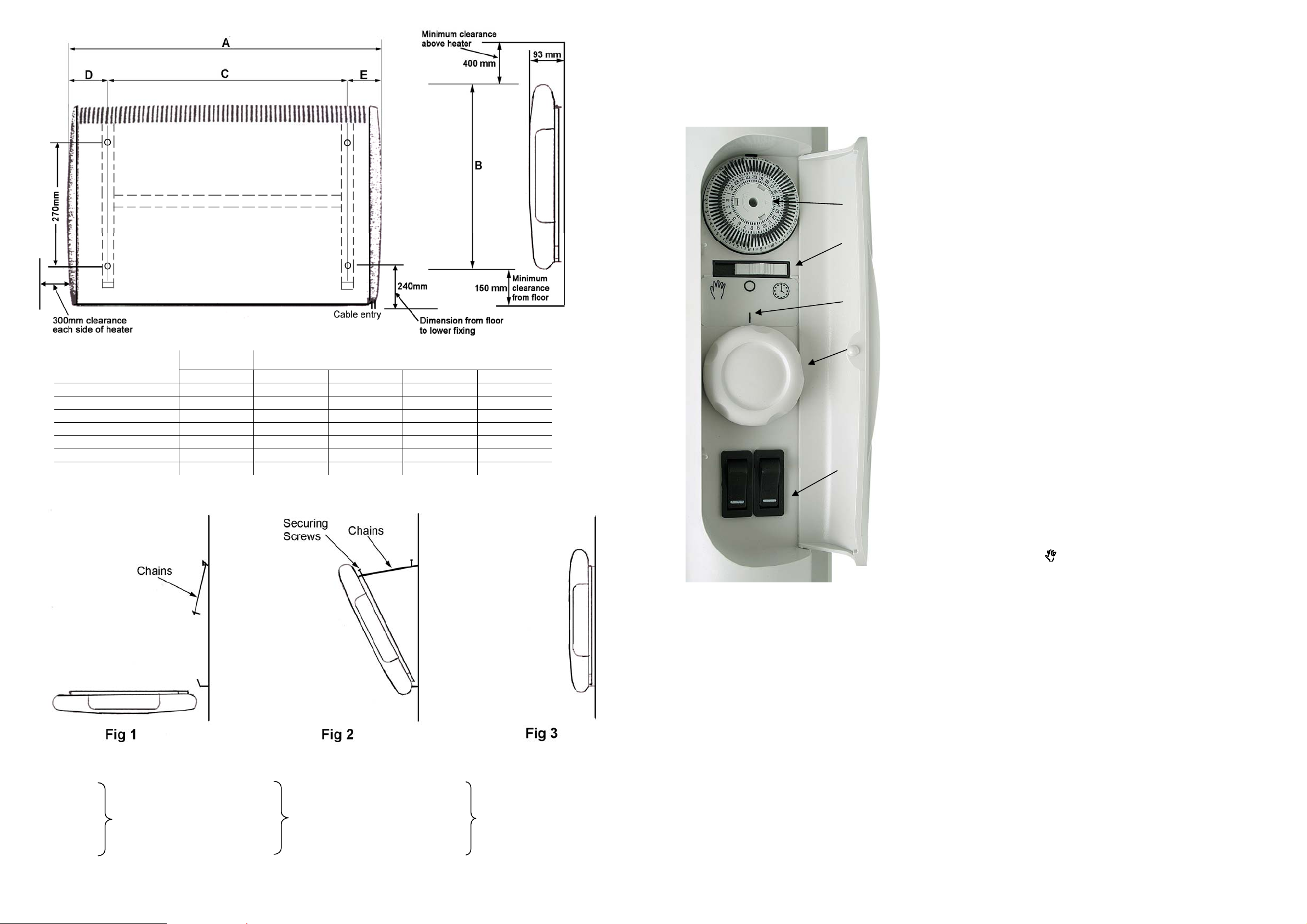
M
ILLIMETRES
WATTS A B C D
PLC050/NC/TI(SS) 500 442 430 196 123
PLC075/NC/TI(SS) 750 442 430 196 123
PLC100/NC/TI(SS 1000 614 430 364 125
PLC125/NC/TI(SS) 1250 614 430 364 125
PLC150/NC/TI 1500 680 430 448 116
PLC150/NC/TISS 1400 680 430 448 116
PLC200/NC/TI(SS) 2000 852 430 616 118
CONTROLS
When the appliance is connected to the mains supply and the wall socket is switched ‘ON’ the mains neon indicator will light, showing
that the power is available to the unit.
The controls (except NC models) are located behind a cover on the
NB: On the non-timer models there is
no timer control and selector switch.
Timer
reference
mark
Selector
Switch
Thermostat
reference
mark
Thermostat
adjustment
knob
Heat Switches
(Each gives half
heat, both
depressed – full
heat)
right hand end of the appliance.
The heaters (except the NC models) are fitted with a build-in
thermostat to control the temperature level to which the room is heated.
The thermostat adjustment knob is located on the right hand end and is
numbered. Rotate the knob clockwise to a higher number against the
thermostat reference mark to raise the room temperature. Once set it is
unlikely to require being touched again.
To set the heater to the Frost Watch mode, turn the thermostat
control knob fully anti-clockwise until the frost symbol aligns with mark.
USING THE TIMER (TI Models only)
The heater must be connected to the mains supply in order for the
timer to operate continuously.
Set the current time of day onto the timer by rotating the dial face
clockwise until the correct time is indicated against the timer reference
mark on the 24-hour clock face.
AUTOMATIC OPERATION
Move the switch immediately beneath the timer to the auto position
designated .
1. The 24-hour timer can be set to give any combination of On/Off
2. The timer can be set to give as many ‘On’ periods as required during
3. This program will repeat itself every 24 hours until changed. This
m
intervals to a minimum of 20 minutes on. Select the ‘On’ time
required by pressing the black segment (on the circumference of the
timer) adjacent to the time required outwards. This will cause the
heater to switch ‘On’ at the selected time for 20 minutes operation.
Each additional segment pressed out will give a further 20 minutes of
operation. In this way, select the length of time required for the unit
to be ‘On’ and push out the number of 20-minute segments necessary
to select the time period required.
any 24-hour period.
program may be overridden at any time by switching to manual
operation.
MANUAL OPERATION
MODELS
PLC050/SS PLC050TI/SS PLC050NC/SS
PLC075/SS PLC075TI/SS PLC075NC/SS
PLC100/SS PLC100TI/SS PLC100NC/SS
PLC125/SS PLC125TI/SS PLC125NC/SS
PLC150/SS PLC150TI/SS PLC150NC/SS
Thermostat
and
Switches
PLC200/SS PLC200TI/SS PLC200NC/SS
Thermostat
Switches
and Timer
No
Controls
Move the rocker switch immediately beneath timer to the manual
position designated . The heater will now run continuously, controlled
by the heat settings and thermostat as described under ‘Controls’.
THERMAL OPERATED CUT-OUT
The appliance is fitted with an Electronic Safety Control (ES). This is a safety device, which switches the heater off if, for any reason,
the appliance overheats. The ES control can only be re-set after the appliance has cooled down. In order to re-set the ES control, proceed as
follows:
• Switch off appliance and leave for approximately 5 minutes.
• Switch appliance back on and ES control will re-set.
• Ensure that the appliance is functioning correctly. If the ES control operates again, the appliance should be checked by a competent
electrician.
The heater carries a ‘Do Not Cover’ label to warn the user that if the appliance is covered, there is a risk of overheating.
CAUTION – In order to avoid a hazard due to inadvertent resetting of the thermal cutout, this appliance must not be supplied through an
external timer or connected to a circuit that is regularly switched on and off by the utility.
MOUNTING
This unit is for wall mounting only; the wall bracket supplied must be used.
1. Remove wall bracket from the heater, with the chains attached, by removing the 2 securing screws from the top of the rear panel.
2. Fix wall bracket to wall using screw holes (4 off) provided.
3. Fig 1: Present heater to bracket
4. Fig 2: Locate heater onto bottom lugs via 2 sets of relevant slots in rear panel. Hinge heater upwards and replace screws with
link plates of chain attached, then move heater to upright position. The link plates should slide under the slotted bracket lip.
5. Fig 3: Tighten both retaining screws.
The heater must not be located immediately below a fixed socket outlet.
66000059 Iss 07
Page 2
CONNECTION TO THE MAIN SUPPLY
Electrical installation should be carried out by a competent installer, preferably registered with NICEIC (National Inspection Council for
Electrical Installation Contracting) in accordance with the 16 edition of the IEE Wiring Regulations, (BS.7671), and any relevant Local
Authority Bye-Laws.
This heater is fitted with a 3-core mains supply cable and should be permanently connected to the electricity supply via a double pole
switch having 3mm gap on each pole.
A switched Fused Connection unit to BS.1363. Part 4 is a recommended mains supply connection accessory to ensure compliance with
safety requirements applicable to fixed-wiring installation.
Note: When switched on for the first time the appliance may emit a slight smell. This is purely the evaporation of a fluid used in the
manufacturing process.
WARNING: This appliance must be earthed.
CLEANING
Always disconnect the heater from the mains before cleaning.
The heater should not require any maintenance, but it is strongly advised that it is kept clean. An occasional wipe over with a soft cloth
is all that should be necessary.
• Do NOT use metal or furniture polish on any part of the heater
• Do NOT touch the heater with wet hands or in any way bring water into contact with it.
If the supply cord is damaged, it must be replaced by the manufacturer or its service agent or a similarly qualified person in order to avoid
a hazard.
SAFETY
QUALITY SPACE HEATERS
INSTALLATION, OPERATION AND MAINTENANCE INSTRUCTIONS FOR
CONSORT PANEL CONVECTOR HEATERS
PLEASE RETAIN THIS LEAFLET FOR FUTURE MAINTENANCE
This equipment has been designed and manufactured to the highest international standards, but, like all electrical appliances which are
operated by mains voltage, care must be taken if you are to obtain the best results and safety is to be assured.
NOTE: The appliance is not intended for use by persons (including children) with reduced physical, sensory or mental capabilities, or
lack of experience and knowledge unless they have been given supervision or instruction concerning use of the appliance by a person
responsible for their safety.
Children should be supervised to ensure that they do not play with the appliance
• Do NOT site the appliance into a corner.
• Do NOT handle the appliance with wet hands.
• Do NOT use the appliance in workshops or rooms where excessive dust is generated or present.
• Ensure that nothing is pushed into any aperture of this appliance.
• Do NOT touch outlet grille when the appliance is in use.
• Do NOT cover or restrict any aperture of the appliance when in use.
• Do NOT use the appliance if damaged.
• Do NOT leave the appliance unattended where young children are present.
• If used in a bathroom, the heater is to be installed so that the switches and other controls cannot be touched by a person in the bath
or shower.
This appliance meets the requirements of EU Directive 89/336 for EMC.
NOTE: The rating label can be viewed by loosening the two mounting bracket screws and hinging the appliance forward on its retaining
chains.
IF YOUR HEATER DOES NOT WORK
• Check that power is available to the heater. The neon in the control switch should be illuminated.
• Check that the thermal cut-out has not operated. Follow the reset instructions given under the section headed ‘Thermal Operated
Cut-out’.
• Check that the fuse in the spur unit has not blown. This can be done by replacing the fuse with another suitable fuse.
Should neither of the above remedies work, then telephone the helpline number shown in these instructions. (UK ONLY).
• Do not attempt to repair the heater.
GUARANTEE
Catalogue Numbers: PLC050/SS PLC050TI/SS PLC050NC/SS
PLC075/SS PLC075TI/SS PLC075NC/SS
PLC100/SS PLC100TI/SS PLC100NC/SS
PLC125/SS PLC125TI/SS PLC125NC/SS
PLC150/SS PLC150TI/SS PLC150NC/SS
PLC200/SS PLC200TI/SS PLC200NC/SS
Please note: ‘SS’ suffix added to model number denotes Stainless Steel derivative
‘PLCF’ models are fitted with an additional frost protection thermostat
This guarantee is offered to you as an extra benefit and does not affect your legal rights.
All electrical appliances produced for the Company are guaranteed for one year against faulty material or workmanship. This applies
only if the appliance has been used for purposes in accordance with the instructions provided and has not been connected to an unsuitable
electricity supply, or subject to misuse, neglect, damage or modified or repaired by any person not authorised by us.
The correct electricity supply voltage is shown on the rating label attached to the appliance.
CUSTOMER HELPLINE
Should you need any advice on the use of your new Consort product, or should you require service or repair, please contact our Helpline:
§ 01646 692172 Mon to Fri 8.30 am to 3.30 pm
Consort Equipment Products Limited
Thornton Industrial Estate, Milford Haven, Pembrokeshire, SA73 2RT
Tel: 01646 692172 Fax: 01646 695195
Email: [email protected]
Web: www.consortepl.com
66000059 Iss 07
 Loading...