

Consew CN3115RB-1 User Manual

CONSOLIDATED
SEWING
MACHINE
CORP.
L
INDUSTRIAL
SEWING & CUTTING
EQUIPMENT
lnstructi n & Parts
. Manual

Intentionally left blank
Contents
1 . Brief introduction · · ·
2 . Main specifications .................... · · · · · · · · · · · · ...... · ·
3 . Installation and preparation · · ·
3 . 1 . Installation · .. · .. · ·
3.
1 . 1 . Location
3.
1.
2.
Installing drip pan
3.
1.
3.
Mounting machine head · · ·
3.1.4.
3.
3.
3.
3.
3.2.3.
3.2.4.
4.
4.
4.
4.
4.
4.
4.
4.
4.
4.
4.
Installing bobbin winder
1.
5.
Mounting knee lifter .. · · · ·
2.
Preparation .. · .. · ·
2.
1 . Cleaning machine ·
2. 2.
Examination · · · ..
Oiling
Trial - run
Operation ........................................................................................................................ 3
1 . Selection
2.
Installing needle ·
3 . Threading needle thread
4.
Winding bobbin thread · · · · · · · · · · · · .. · .. · .. · .. ·
5 . Replacing bobbin · .. ·
6.
Adjusting thread tension · · ·
6 .1 . Adjusting thread take - up spring .. · · · · · · .. · · · · · · · · .. · ·
6.
2.
Adjusting tension of needle thread and bobbin thread
7.
Adjusting stitch length
8.
Adjusting pressurt
of
...........................................................................................................................
of
sewing thread
.... · ..................
sewing machine · ·
.. · .. · .... · .. · ....
.....................................................................................................................
....
of
·.
· ................. · · · ·
· · .. · .. ·
..
· · .. · .. · .. · · · .. · · · .. ·
..
· .. · ·
.... · .... · ......
....
· · · · · · · · .. · · · ·
......................................................................................................
....
· · .. · · · · · · · .. ·
· · · · · .. · .. · .. · .. ·
.... · .. · ....
·"
· · · · · ·
· · · · .. ·
and
....
.....
presser foot
· · · · · .. · .. · .. · .. ·
..
· · .. · .. · .. · .. · · · · · · .. · · · · · .. · ·
.. · .... · ....
....
drawing bobbin thread
· · .. · · .. · ·
....
· ·
· ·
....
· · · · · .. · · · · .. · · · · .. · · ·
....
· · .. · .. · · · .. ·
· · .. · .. · .. · .. · · ·
..
· ·
.. · ....
· ·
....
· ·
............
.. · ..
..
· · · · · · ....... ·
.... · .... · ........
· .. · .. ·
........
....
· · · · · · .. ·· · .. ·
..
· · · · .. · .. · ·
......
...... · ....
· · ·
..
· ·
............ · ....
....
..
· · · ·
.. · ..
......
.... · ....
......
· ·
....
· ·
· ·
....
· ........ · ...................... · ·
....
· ..... · ................ · · · ..... · · · · · · · · · · · · · ·
·· .. · ..
· · · · · · · · ....... ·
· .. ·
....
· · .. · ·
.... · .. · ............
....
· .. · .. ·
........
· ·
....
· · · · · · · ·· ·
· · ·
..
· .. · .. · ·
................
· .. · .. ·
· .. · .. · · .. ·
· ·
· .. ·
...... · ................ · ....
....
· .. ·
..
· · · · · · ·
......
....
· .. · · · ·
· .. ·
....
· ·
· · · · ·
..
· · · · · · · .. ·
.... · ........
· · · · · · · ·
....
· · · · · ·
..
· .. · .. · .. · ·
....
....
· ·
.......... · ....
...... · ..
........
· · .. ·
....
· · .. · .. ·
......
· .. · .. ·
....
......
"·
.. · ·· ·
...... · ....
....
· · .. · · · ·
..
......
..
· · · · · · · .. ·
· ·
..
· ·
..
....
· · .. ·
....
· · .. ·
· · ·
....
· .. · .. · .. · · · · · .. · · · · · · .. · .. · · · · .. · ·
........ · .............. · .. · .. · .............. · ......
....
· · ·
.. · ..
.. · ..
· .... · · · · · · · · · · ·
· .. · · · · · · · · · · · · · · · · .. · .. · · · ·
· ..
·· ..
· .. · ·
.. · .......... · ................
· .. · .. · · · · .. · · · · .. · · ·
....
· · .. · · · · · · · .. · · · · · · · · · .. ·
· · · · .. · • · ·
· .. · .. ·
" · · · · · · · · · ·
· .. · · ·
· · · .. ·
· ·
· · · ·
.... · ......
....
· · · · · .. · .. · .. · ·
....
· ·
..
· · · · .. · ·
..
· · · · .. · ·
.... · .... · ...... · ..
..
· .. · .. · · · · · · · · ·
..........
......
· · .. · · · · .. · .. · .. · .. ·
....
· ·
..
· ·
....
..
· ·
....
· · · · ·
· · ·
.. · ....
· .. ·
· ·
.... · .... · .. · .... · ....
· · · · · · · · · · · · · · · · · · ·
..
· · · .... · · · · 1
.. · ..
· ·
..
· · ...... · · · · · · · I
· · .. · .. · · · ·
· · ·
· .. · · ·
....
...... · ...... · .... · .... · ·..
... · ··
....
.... · ....
....
..
· .. · .. · ·
.... · ..
· · ·
....
..
· · · ·
...... · ..
.... · ....
· · · · .. · ·
....... · ·..
...... · .. · ·"
........ · .... · ·..
· "
....
· · · .. ·
· ·
.... · ..
· ·
....
· .. ·
..........
· · ·
......
· · · · · · ·
......
· · ·
............
· ·
....
· ·
...... · .. · ..
........
· · · ·
..
· ·
..
·..
·..
· · · · · · · · · 1
·..
..
· · · · 2
· ·
·..
· 3
....
· 4
.. · ..
· · 4
· · ·
..
· 4
· .. · · ·
..
· 4
· · · · 5
· · ·
..
· 6
· · 6
....
·..
I
1
I
1
1
2
2
2
2
3
8
8
Parts catalog
1.
Arm with Bed .........................................................................................................
2.
Needle Bar and Thread
3.
Shuttle Mechanism ................................................................................................
4.
Feed Mechanism ....................................................................................................
5.
Stitch Length Regulating Mechanism ..................................................................
6.
Presser Foot Mechanism .......................................................................................
7 . Bobbin Winder
8 . !(nee Lifter
9.
Thread U n wmder ..................
10.
Accessories ................................................................................................................... 27
..
· · · ·
··
· · ... · · ·
..
· · ·
Take-up
..
· · · · .... · · · · · ·
..
· · · · · · · · · · ·
Mechanism ...................................................
··
· · · · ·
..
· · · ·
.. · ··
.....
···
· · · · ·
.. · .. · ..
· · · · · · · · · · · · ·
··
.....................................................................................
.. · .. · ..
· · · · · · ·
.. · ..
.. · ..
· ............ ·
· · ·
..
· · · · ·
..
· · · · ·
..
..
·· · ··
· · · · ·
... · ..
..
· ·
.. · .. · .. · ...
· ... ···
.. · ··
··
12-13
14-
1618-
20-21
·
22-
· 24
9-11
~
15
17
19
23
25
26
l.BRIEF
INTRODUCfiON
This sewing machine
sewing a wide variety
The
machine adopts lind thread take length· adjustment; and
stitch form and convenient operation can be guaranteed.
2.
MAIN SPECIFICATIONS
1 . Max. sewing speed
2.
Max.stitch length
3.
Presser foot lift
4.
Max . thickness
5.
Needle
bar
stroke:
is
a low speed, single needle 2 - thread lockstitch industrial sewing machine designde for
of
products including apparel, caps & shoes, luggage, leather articles and canvas products.
up,
shuttle for thread looping, lever type reverse feed and dial for stitch
is
provided with knee lifter mechanism. So the stable running, beautiful and uniform and tidy
1600 spm
5 mm
6.5
mm
6.5
mm
37.4
mm
3.1NSTALLATION AND PREPARATION
3 . 1 . Installation
3 . 1 . 1 . Location of sewing machine
To
ensure a smooth running ,'the machine should be located on rigid and flat floor, seating machine stand on rubber
mat could further reduce the running noise and vibration.
3 . 1 .
2.
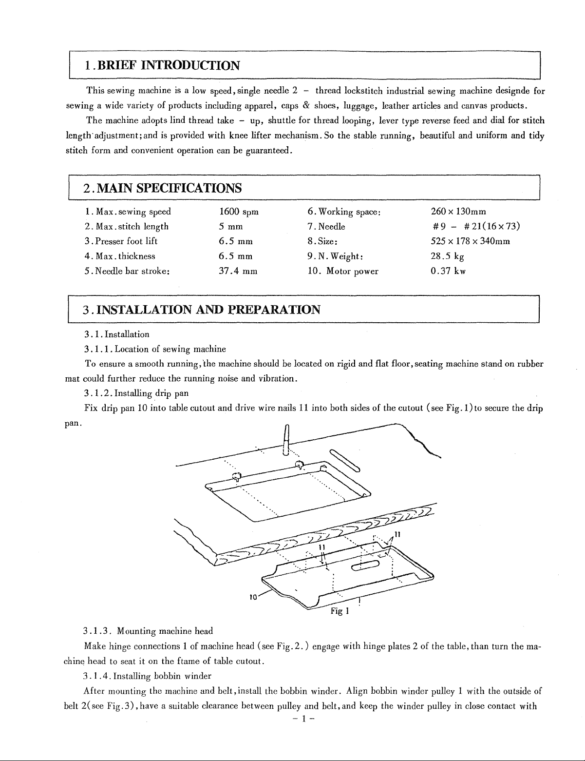
Installing
Fix drip pan 10 into table cutout and drive wire nails
pan.
drip
pan
6.
Working space:
7.
Needle
8.
Size:
9.N.
Weight:
10. Motor power
11
into both sides of the cutout
260x
130mm
#9-
525 x 178 x 340mm
28.5
0.37
(see
#21(16x73)
kg
kw
Fig. 1
)to
secure the drip
.1.3.
3
Make hinge connections 1 of machine head (see Fig.
chill(~
head to seat
3.
After mounting the machine and belt, install the bobbin winder. Align bobbin winder pulley 1 with the outside of
2(
belt
Mounting machine head
it
on the ftame of table cutout.
1 .
4.
Installing bobbin winder
see Fig.
3),
have a suitable clearance between pulley and belt, and keep the winder pulley in close contact with
2.)
engage with hinge plates 2 of the table, than turn the rna-
-
1-
the belt as the bobbin winder stot latce lever 9
screw
4.
1
2
is
pressed down, then, secure
the
bobbin winder on the table with wood
Fig. 2
3.
1.
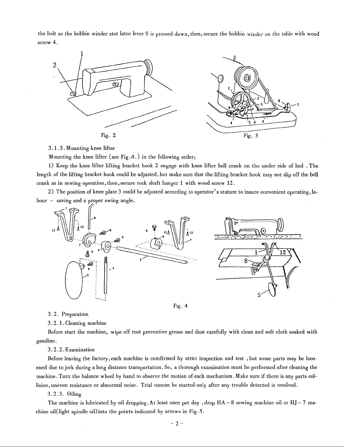
5.
Mounting knee lifter
(see
Fig
.4.
Mounting the knee lifter
1) Keep the knee lifter lifting bracket hook 2 engage with knee lifter bell crank on the under side of bed .
length of
crank as
hour
the
lifting bracket hook could
in
sewing operation,
2)
The
position of knee plate 3 could be adjusted according to
then,
) in the following order:
be
adjusted,
secure rock shaft hanger 1 with wood screw 12.
hut
make sure that
the
lifting bracket hook may not slip off the hell
operator's
stature to insure convenient operating, la-
Fig. 3
The
Fig.
4
3 . 2. Preparation
3 .
2.
1 . Cleaning machine
start
Before
gasoline.
3.
2.
2.
Before leaving the factory, each machine
ened due to jerk during a long distance transportation.
machine.
lision, uneven resistance
chine oil
Turn
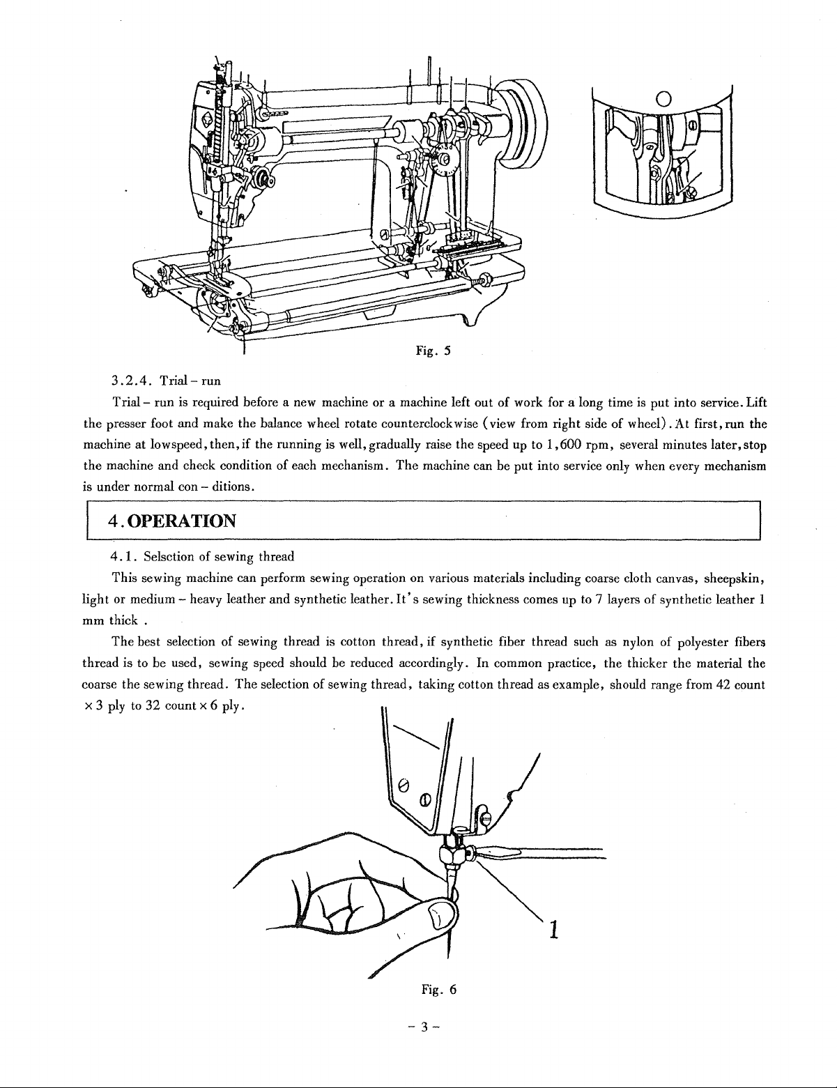
3 . 2 . 3 . Oiling
The
machine is lubricated by oil dropping. At least once per day , drop
(light
the machine, wipe off rust preventive grease and dust carefully with clean
Examination
is
com firmed by strict inspection and test ,
So, a thorough examination must he performed after cleaning the
the balance wheel by hand to observe the motion of each mechanism. Make sure
or
abnormal noise. Trial runcan he started only after any trouble detected
spindle oil) into the points indicated by arrows in Fig.
5.
-2-
and
but
HA-
8 sewing machine oil or
soft cloth soaked with
some parts may he loos-
if
there
is
any parts col-
is
resolved.
HJ-
7 ma-
3.2.4.
Trialthe presser foot and make the balance wheel rotate counterclockwise (view from right side
machine at lowspeed,
the machine and check condition of each mechanism.
is under normal
Trial-
run
run
is required before a new machine or a machine left out
then,
if
the running is well, gradually raise the speed up to
The
machine can be
con-ditions.
of
work for a long time
1,600
rpm,
put
into service only when every mechanism
4.0PERATION
4.
1 . Selsction of sewing thread
on
This sewing machine can perform sewing operation
light or
mm
thread is to be used, sewing speed should be reduced accordingly.
coarse the sewing thread.
X 3 ply to
medium-
thick.
The
best selection of sewing thread is cotton
32
heavy leather and synthetic leather.
The
selection of sewing thread, taking cotton thread as example, should range from
count X 6 ply.
thread,
various materials including coarse cloth canvas, sheepskin,
It's
sewing thickness comes up to 7 layers
if
synthetic fiber thread such as nylon of polyester fibers
In
common practice, the thicker
is
put into service. Lift
of
wheel).
several minutes
At
of
synthetic leather 1
the
first,
run
the
later,stop
material the
42
count
Fig. 6
-3-
4.
2.
Installing needle
Turn
the balance wheel until the needle bar reachs to its highest position, loosen needle clamp screw 1 (see Fig.
5),
while keeping the long groove of needle facing the left, insert the needle shank into the hole of the needle bar
tom end as far as it will go, then tighten needle clamp screw
4.
3.
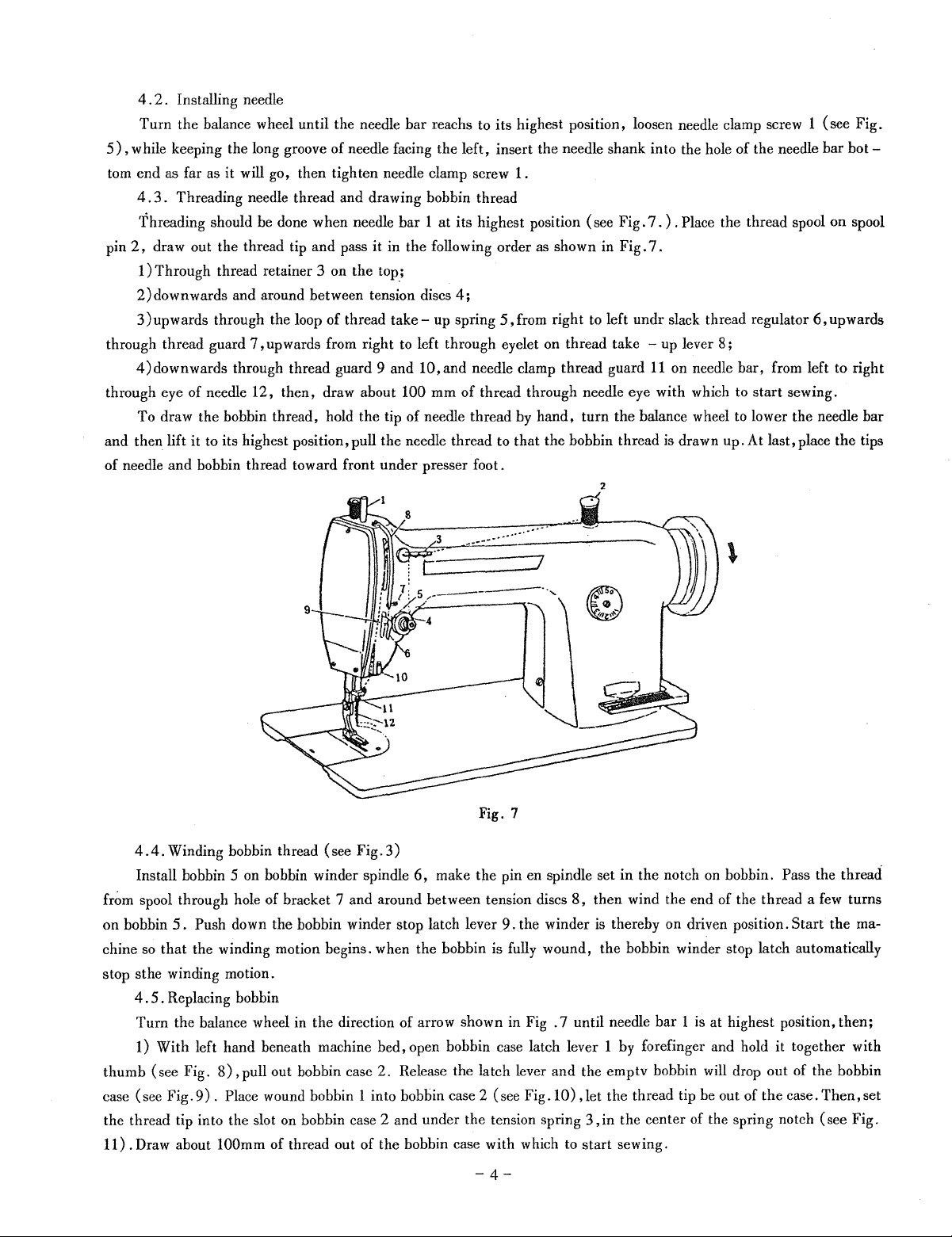
Threading needle thread and drawing bobbin thread
Threading should be done when needle bar 1 at its highest position (see Fig.
2,
draw out the thread tip and pass it in the following order as shown in Fig.
pin
1)
Through thread retainer 3 on the
2)downwards and around between tension discs
3)upwards through the loop
through thread guard
4)
down wards through thread guard 9 and
through eye of needle 12, then, draw about
To draw the bobbin thread, hold the tip
and then lift it to its highest position, pull the needle thread to that the bobbin thread is drawn up. At last, place the tips
of needle
and
bobbin thread toward front under presser foot.
7,
upwards from right to left through eyelet on thread take - up lever
of
thread
top.;
4;
take-
up spring
10,
and needle clamp thread guard
100 mm
of
of
needle thread by hand, turn the balance wheel to lower the needle bar
1.
7.).
Place the thread spool on spool
7.
5,from
thread through needle eye with which to start sewing.
right to left undr slack thread regulator
8;
11
on needle bar, from left to right
2
bot-
6,upwards
Fig. 7
4.
4.
Winding bobbin thread (see Fig.
Install bobbin 5 on bobbin winder spindle
fr~m
spool through hole of bracket 7 and around between tension discs
on bobbin
chine
stop sthe winding motion.
thumb (see Fig.
case (see Fig.
the thread tip into the slot on bobbin case 2 and under the tension spring
11) . Draw about
5.
Push down the bobbin winder stop latch lever
so
that the winding motion begins. when the bobbin is fully wound, the bobbin winder stop latch automatically
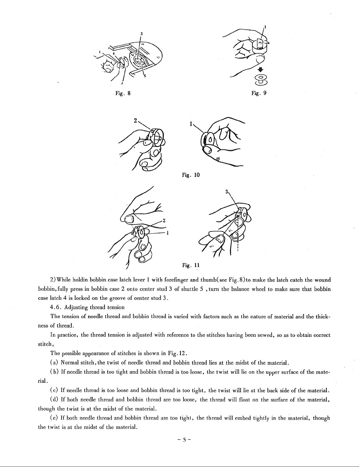
4 . 5 . Replacing bobbin
Turn the balance wheel in the direction of arrow shown in Fig . 7 until needle bar 1
1) With left hand beneath machine bed, open bobbin case latch lever 1 by forefinger and hold it together with
8),
pull out bobbin case
9).
Place wound bobbin 1 into bobbin case 2 (see
lOOmm
of thread out of the bobbin case with which to
3)
6,
make the pin en spindle set
8,
9.
the winder
2.
Release the latch lever and the emptv bobbin will drop out of the bobbin
Fig.IO),
-4-
in
the notch
then wind the end of the thread a
is
thereby on driven position.
let the thread tip be out of the case.
3,
in the center of the spring notch (see Fig.
start
sewing.
on
bobbin. Pass the thread
few
Start
is
at highest position, then;
Then,set
turns
the ma-
3
Fig. 8
Fig.
Fig.
Fig. 9
10
II
2)While holdin bobbin case latch lever 1 with forefinger and thumb( see
bobbin, fully press in bobbin case 2 onto center stud 3 of shuttle 5 , turn the balance wheel to make sure
case latch 4 is locked on the groove of center stud 3 .
4.
6.
Adjusting thread tension
The
tension
ness of thread.
In
practice, the thread tension is adjusted with reference
stitch,
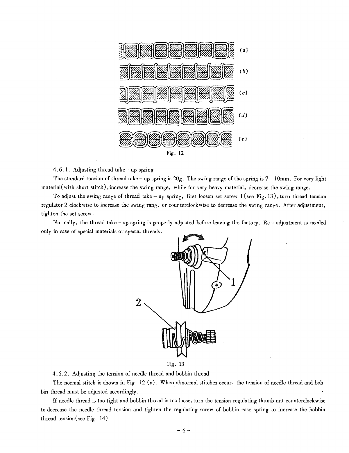
The
possible appearance of stitches
(a)
Normal stitch, the twist of needle thread and bobbin thread lies at the midst
(b)
If
rial.
(c)
If
(d)
If
though the twist
(e)
If
the twist is at the midst of the material.
of
needle thread and bobbin thread is varied with factors such as the nature of material and the thick-
to
the stitches having been sewed,
is
shown in Fig. 12.
needle thread is too tight and bobbin thread
needle thread is too loose and bobbin thread is too tight, the twist will lie at the back side
both needle thread and bobbin thread are too loose, the thread will float on the surface
is
at
the midst of
both needle thread and bobbin thread are too tight, the thread will embed tightly
the
material.
is
too loose, the twist will lie on the upper surface
Fig.S)to
make the latch catch the wound
so
as
to
of
the material.
of
of
in
the material, though
-5-
that
bobbin
obtain correct
of
the mate-
the material.
the material,
(a)
(b)
(c)
(d)
(e)
Fig.
12
4.
6.
1 . Adjusting thread take - up spring
The
standard tension
material( with short stitch) ,increase the swing range, while for very heavy material, decrease the swing range.
To
adjust the swing range
regulator
tighten the set screw.
only in case
2 clockwise to increase the swing
Normally, the thread
of
special materials
of
take-
thread
take-
up spring
of
thread take - up spring, first loosen set screw 1
rang,
up spring is properly adjusted before leaving the factory. Re - adjustment is needed
or
special threads.
is
20g.
The
swing range
or
counterclockwise to decrease the swing range. After adjustment,
of
the
spring is 7-10mm.
(see
Fig.
13) ,
For very light
turn
thread tension
2
Fig.
13
4.
6.
2.
Adjusting
The
normal stitch is shown in Fig. 12
bin thread
to decrease the needle thread tension
thread tension (see Fig. 14)
must
If
needle thread
the
tension
be
adjusted accordingly.
is
too tight and bobbin thread is too loose, turn the tension regulating
of
needle thread and bobbin thread
(a).
When abnormal stitches occur,
and
tighten the regulating screw
-
6-
the
tension
of
bobbin case spring to increase the bobbin
of
needle thread and bob-
thumb
nut
counterclockwise
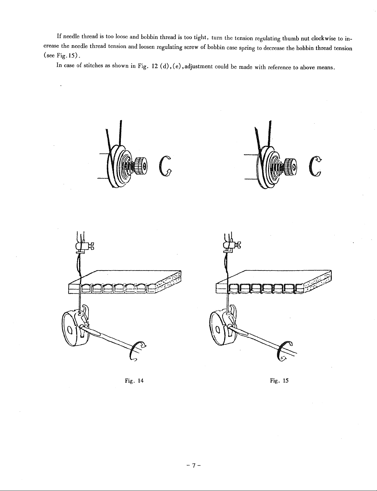
If
needle thread
crease the needle thread tension and loosen regulating screw
(see
Fig.l5).
is
too loose and bobbin thread is too
tight,
turn the tension regulating thumb
of
bobbin case spring to decrease the bobbin thread tension
nut
clockwise to in-
In case
of
stitches as shown in Fig. 12
(d),
(e),
adjustment could be made with reference to above means.
Fig.
14
-7-
Fig.
15
4.
7.
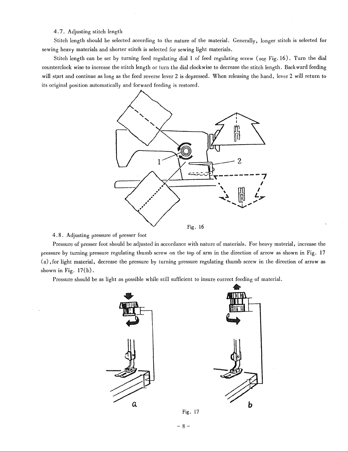
Adjusting stitch length
Stitch
length should be selected according to
sewing heavy materials and
Stitch
length ean be set by turning feed regulating dial 1 of feed regulating screw (
counterclockwise
will st,art
its original position automatically
and
to increase the stitch length
continue
as
long as
shorter
(
the
nature
of
the material. Generally, longer stitch is selected for
stitch is selected for sewing light materials.
or
turn
the dial clockwise to decrease the stitch
the
feed reverse lever 2 is depressed.
and
forward feeding is restored.
When
releasing
the
St:<y
length.
hand,
Fig.
16).
Backward feeding
lever 2 will
Turn
the dial
return
to
fig.
16
4.
8. Adjusting pressure
of
Pressure
pressure by turning pressure regulating
(a)
, for light material, decrease the pressure by turning pressure regulating
shown
in
Pressure should be as light as possible while still sufficient to insure correct feeding
presser foot should be adjusted in accordance with
Fig.
17(b).
of
presser foot
thumb
nature
screw on the top of arm
of
materials.
in
the
For
heavy material, increase the
direction of arrow as shown in
thumb
screw
in
the direction
of
material.
•
Fig.
of
arrow as
17
a
Fig.
17
-8-
b
 Loading...