


Back Cover
MODEL 75T
Ideal for alteration rooms, tailors, clothing rentals, dry cleaners, department stores, dressmakers and home use
APPLICATIONS
Perfect for sewing all weights of materials including synthetics, woolens, cottons, fabrics and knits
1 to 1 non-skip stitches, typical operations include felling edge tapes, bottoms of trousers, cuffs, wigging in sleeves, facings to canvas and knit goods, turned-up bottoms of fully lined coats, padding collars and lapels, and reinforcing trouser seats
2 to 1 skip stitch for hemming dresses, skirts, slacks, trousers, sportswear, ladies coats, draperies, blouses and other articles
Suitable for felling operations requiring a skip stitch to simulate hand-stitching
2 to 1 skip stitch is recommended for synthetics and other lightweight materials and 1 to 1 for heavier cotton, woolen and linen goods
SPECIFICATIONS
Speed, Max. (S.P.M.) |
1000 * |
|
|
Stitch Length, Max. |
31/2 s.p.i. (7mm) |
Needle Style |
LWX 6T |
|
|
Looper |
471 |
|
|
Cylinder Diameter |
1 5/8" (40 mm) |
|
|
Work Space (Needle to Arm) 4" (100 mm)
Stitch Type |
103 |
* Speed depends on materials, operation and thread
Front Cover
MODEL 75T
ALL PURPOSE, PORTABLE, SINGLE THREAD, CHAINSTITCH, BLINDSTITCH MACHINE
SETUP and OPERATING
INSTRUCTION
MANUAL
PARTS
MANUAL
Specifications subject to change without notice. |
©2015 Consew USA -0815 |
All photographs in this manual are additionally ©2015 - Ron Greenfield / Forest Litho Printing Co.
Specifications subject to change without notice. |
©2015 Consew USA -0815 |
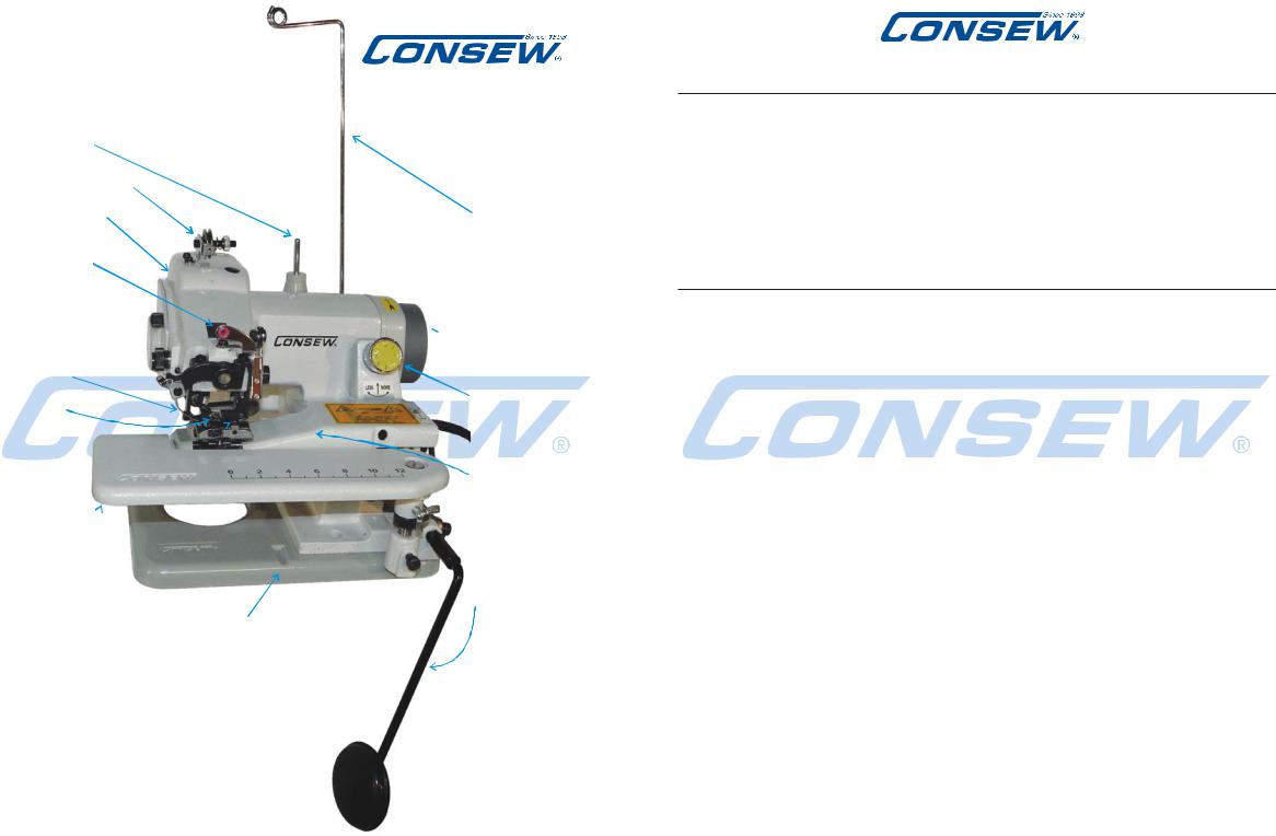
Spool Pin
Thread Tensioner
Machine Arm
Front Thread
Guide
Needle
Looper
Feed Dog
Work Plate
Machine Base
Front Groove for seating of Table Clamp
(There is also a groove on the right side of machine for table clamping from that side.
Either will work)
2
MODEL 75T
Thread Guide
 Hand Wheel
Needle
Penetration
Dial
Cylinder Bed
Knee Lifter
MODEL 75T
SET UP
and
OPERATING
MANUAL
Table of Contents
|
Section |
|
|
Page |
||
|
Number |
Section Description |
Number |
|
||
-- |
Overview Diagram of 75T . . . . . . . . . . . |
2 |
|
|
||
|
|
(This Page) Table of Contents . . . . . . . . . |
3 |
|
|
|
1. |
Setting up Machine for Work . . . . . . . . . . |
4 |
|
|
||
|
|
A. Location . . . . . . . . . . . . . . . . . . |
4 |
|
|
|
|
|
B. Installing Thread Stand . . . . . . . . . . |
4 |
|
|
|
|
|
C. Connecting Motor Controller . . . . . . . |
5 |
|
|
|
|
|
D. Assembly of Knee Lifter . . . . . . . . . |
5 |
|
|
|
|
|
E. Clear Acryllic Sheild . . . . . . . . . . . |
6 |
|
|
|
2. |
Lubrication (The Oil Access Ports) . . . . . . . . |
7 |
|
|
||
3. |
Threading Machine . . . . . . . . . . . . . . |
8-9 |
|
|
||
4. |
Needles and Thread . . . . . . . . . . . . . . |
10 |
|
|
||
5. |
Replacing the Needle . . . . . . . . . . . . . . |
10 |
|
|
||
6. |
Inserting the Work Piece and Starting to Sew . |
11 |
|
|
||
7. |
Adjustment of Thread Tension . . . . . . . . . |
12 |
|
|
||
8. |
Regulating Stitch Length . . . . . . . . . . . . |
13 |
|
|
||
9. |
Adjustment of Needle Penetration . . . . . . . |
14 |
|
|
||
10. |
Removal of the Work from the Machine . . . . |
15 |
|
|
||
11. |
Skip Stitch Device . . . . . . . . . . . . . . . |
16 |
|
|
||
12. |
Side/Back Cover (Notes on Lubrication) . . . . . |
17 |
|
|
||
13. |
Back Cover (Notes on Lubrication) . . . . . . . . |
18 |
|
|
||
|
|
PARTS BOOK: Table of Contents . . . . . . |
19 |
|
|
|
-- |
Specifications & Applications |
. . . . Back Cover |
||||
|
|
|
|
|
||
Specifications subject to change without notice. |
©2015 Consew USA -0815 3 |
|||||
1.Setting Up the 75T Machine for Work
Unpack machine from its shipping box, making certain that you remove from box all component parts and accessories.
A. Location (Figs.1-2)
Place machine on a firm table, preferably near its right front corner. Attach machine near edge of table using table clamp which is included with the accessories. Table clamp is inserted into the groove in base in either the front or on the right side, whichever works easiest.
Make sure machine is clamped tightly to keep it from moving when you are using knee-lift.
See Figs. 1 and 2 for details of clamping.
Open the box and find accessories on top and the 75T on the bottom
From Front of 75T
Fig.1
B. Thread Stand and
Thread Guide Pole. (Fig.3)
First, find the Thread Guide Stud (3); it is black and just above the motor
in the back. Then insert the Thread Guide Pole (2) into the hole in it and tighten the thread guide Clamp Screw (4).
Adjust it so the
Thread Guide Loop (5) extends over the thread spindle (6). The Thread Guide Stud Set Screw (1) can be loosened to adjust the vertical angle of the Thread Guide Pole, and then tightened back up, but as long as the
Loop (5) is over the thread spindle (6), it’s OK.
From Right Side of 75T
Fig.2
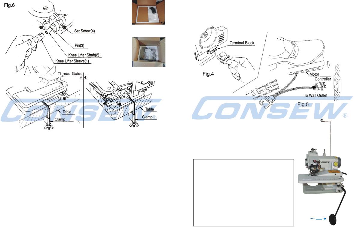
C. Connecting the Motor Controller Pedal (Figs.4-5)
Insert three-hole plug on controller wiring into terminal block at right side of machine and insert standard plug into wall outlet. Place controller on floor and regulate speed of machine by stepping on of floor pedal.
D. Assembly of Knee Lifter (Fig.6)
Push sleeve (1) onto free end of shaft (2) and allow pin (3) to enter L-shaped groove in sleeve. If you need to adjust the angle of
knee lifter, loosen the set screw (4) and adjust the knee lifter to a comfotable angle.
Then, tighten the set screw (4).
Knee
Lifter
4 |
5 |

E. Optional Clear Acrylic Shield
(provided with machine - Fig Shield1)
To Install:
Using the two small screws provided, screw through the metal plate and
the shield into the two screw holes in the swing arm located just to the right of the needle
Fig. Shield 1
assembly. (Fig Shield 2)
MODEL 75T
Fig. Shield 2
In the “Down” position (Fig.Shield3) |
|
the shield helps keep fingers |
In the “Up” position (Fig.Shield4) |
out of the needle area |
it is out of the way |
Fig. Shield 3 |
Fig. Shield 4 |
6
2. Lubrication (Fig.7)
Lubrication is important for the trouble-free operation and long service life of the machine. Therefore, after setting-up machine as per instructions, you should lubricate it before using.
A convenient oil dropper filled with fine machine oil is provided with the tool kit.
(Use a pin to pierce the tip of the spout. Be sure to snap the cap on tightly after opening to avoid leakage. You may want to keep it in a small resealable plastic bag when storing.)
Carefully place a drop sewing machine oil into all the holes indicated by arrows on Fig.7. There are 6 of them. Remember to give the machine a wipe down to remove any residual oi1 that might stain your work.
Lubrication Regimen
As a part of regular daily maintenance, you should oil the 6 oil holes with a drop of machine oil (in Fig.7) before starting work.
Tip: It is suggested that you do this at the end of the previous days work because this would allow any excess oil to settle and with a quick wipe the machine will be clean and ready to go the next day.
Fig.7 OILING POINTS
Note: Internal Lubrication is covered in sections 12 and 13.
7
3.Threading the Consew 75T (Figs.9-12)
Fig. 9 shows the path of thread from the overhead thread guide through the tension nut, through the front guides and to the needle.
Fig.9 |
Thread Guide (1a) |
|
 Tension Disc (2)
Thread Guide (1b) 
Thread
 Tension
Front Thread Guide (3) Nut (6)
Needle Clamp Guide (4a)
Needle Clamp (4)
Needle (5) 
Fig.9B
Hand wheel (7)
A. When using sewing thread from a cone, place it over plastic base on thread stand (Fig.9B above)
B.When using spool thread, remove plastic cone base before placing spool on thread
stand (Fig. 10).
Tip: Many spools of thread have a notch cut at the top edge where the end of the thread is wedged in before being cut off. Put the spool on upside down, so the notched edge is on the bottom and the thread can’t catch on that notch as it unwinds upwards to the thread guide.
C.For correct needle threading of the machine,
carefully follow the path of thread as shown in Fig.9 above and Fig 11 on the next page.
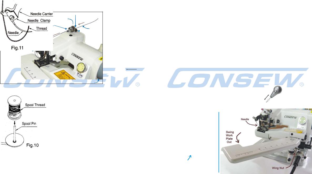
Threading the machine (continued)
Take the thread through the vertical guide pole and pull it to the rear of the thread tension device.
Put the thread first thru the rear thread guide eye (1a);
Then, between the two tension discs (2); and then through the eye of the forward thread guide (1b) as per Fig.9.
Bring the thread to the front of the machine and put it through the plastic grommet which is the front thread guide (3).
Then below that there is a guide hole (4a) on the left of the needle clamp (4). From there the thread continues down to the needle (5).
Important: At this point, make certain that needle is in extreme left-hand position (turn the handwheel (7) so it is. The left edge of the Needle Carrier arm will be at its highest point.)
Now put thread through needle eye from below as shown in Fig.11.
TIP 1: It is easier to get to the eye of the needle (5) when the work-plate is pulled out of the way. Loosen the wing-nut below and to the right of the work-plate amd put the work-plate towards you (Fig 12). Additionally, if you engage the knee-lifter, it will move the Cylinder Bed downward, giving you even more room.
TIP 2: If you are having trouble getting the thread thru the needle, |
Common |
|
a standard needle threading device (available everywhere) might |
||
Needle |
||
help. You would put the device wires thru the needle from the |
Threading |
|
Device |
||
top, put the thread in the wire loop and pull the thread through. |
||
|
Thread the needle from below in an upward direction as in Fig.11.
Fig. 12
8 |
9 |
 Loading...