

Consew CN2230R User Manual
I
OPERATING
LON
CONSOLIDATED SEWING
~IONS,
P~RTS
LIST
SEW
model
CN
2230
MACHINE
CORP.
R
CONSOLIDATED SEWING
COPYRIGHT@1989
CONSOLIDATED
MACHINE
SEWING
MACHIN£
CORP.
CORPORATION
SPECIFICATIONS
-CON
SEW
Model
medium
driven
located
and
and
automatically
at
the
medium
CN
22300
underside
is
designed
heavy-weight
lubricated
of
the
for
lock
materials
by
machine
stitch
at
means
bed.
sewing
speeds
of
a
pressure
up
of 1 igh
to
5000
pump
t,
-Maximum
-~aximum
-Needle
IMPORTANT NOTE
Do
not
been
on
page
HOW
TO
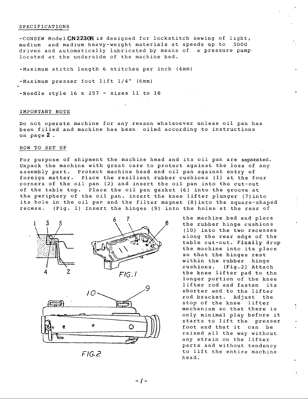
For
purpose
Unpack
assembly
foreign
corners
of
the
the
periphery
its
hole
recess.
operate
filled
2 .
SET
the
table
stitch
presser
style
and
UP
machine
part.
matter.
of
the
in
(Fig.
of
the
length
16
machine
machine
shipment
Protect
oil
top.
of
oil
1)
foot
x
257
with
Place
pan
Place
the
Insert
oil
pan
6
lift
-
for
has
the
great
machine
the
(2)
and
stitches
1/4"
sizes
any
been
machine
resilient
and
the
oil
pan,
the
the
hinges
(6mm)
11
reason
care
head
insert
insert
filter
per
to
oiled
pan
inch
18
whatsoever
head
to
protect
and
rubber
the
gasket
the
(9)
(4mm)
according
and
oil
oil
knee
magnet
into
uriless
its
oil
against
pan
against
cushions
pan
(6)
into
lifter
(8)into
the
holes
to
instructions
pan
(1)
into
the
plunger
oil
are
the
loss
entry
at
the
groove
the
square-shaped
at
the
pan
separated.
of
of
the
cut-out
(7)into
rear
has
any
four
at
of
FIG.2
6 7
FIG.!
8
the
machine
the
rubber
(10)
along
table
the
so
within
cushions.
the
longer
lifter
shorter
rod
stop
mechanism
only
starts
foot
raised
any
parts
to
head.-
into
the
cut-out.
machine
that
knee
bracket.
of
minimal
and
strain
and
lift
the
rear
the
the
lifter
portion
rod
end
the
so
to
lift
that
all
without
the
bed
hinge
two
into
hinges
rubber
(Fig.2)
and
to
Adjust
knee
that
play
it
the
on
the
entire
and
cushions
recesses
edge
Finally
its
rest
hinge
Attach
pad
of
the
fasten
the
lifter
lifter
there
before
the
can
way
without
lifter
tendency
machine
place
of
the
drop
place
to
the
knee
its
the
presser
be
is
it
-I-
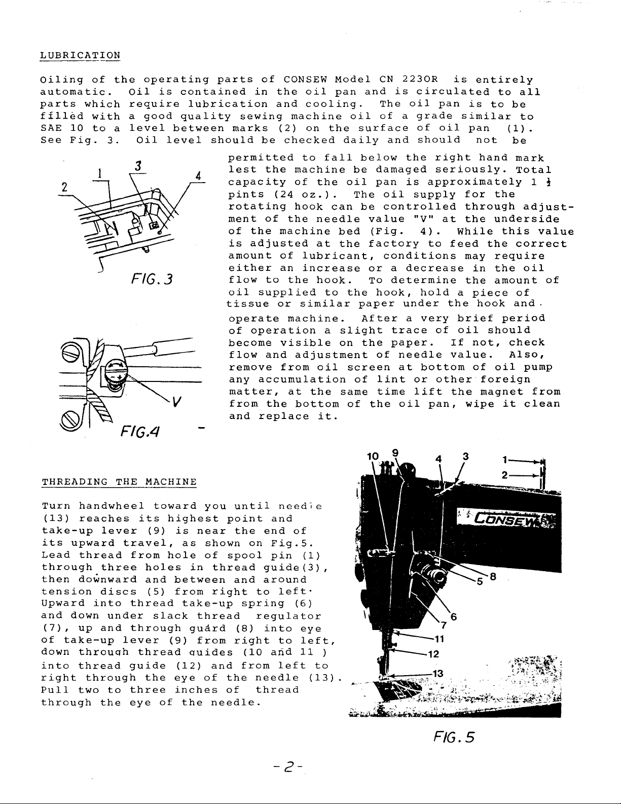
LUBRICATION
Oiling
automatic.
parts
filled
SAE
10
See
Fig.
of
which
with
to
3.
the
Oil
require
a
a
operating
good
level
Oil
3
is
between
level
parts
contained
lubrication
quality
should
of
in
sewing
marks
be
permitted
lest
capacity
pints
rotating
ment
of
the
is
adjusted
amount
either
flow
oil
supplied
tissue
operate
of
operation
become
flow
remove
any
accumulation
matter,
from
and
replace
CONSEW
the
and
(2)
checked
the
(24
of
machine
of
an
to
or
visible
and
from
the
oil
cooling.
machine
on
to
fall
machine
of
the
oz.).
hook
the
needle
at
lubricant,
increase
the
hook.
to
similar
machine.
a
adjustment
oil
at
the
bottom
it.
Model
pan
the
daily
oil
can
bed
the
the
slight
on
screen
same
of
and
oil
surface
below
be
The
be
value
(Fig.
factory
or
To
paper
After
the
of
the
CN
2230R
is
The
oil
of
a
and
the
damaged
pan
is
oil
controlled
conditions
a
decrease
determine
hook,
under
a
trace
paper.
of
needle
at
lint
time
oil
is
circulated
pan
grade
of
should
approximately
supply
"V"
4).
to
hold
very
bottom
or
lift
pan,
similar
oil
right
seriously.
at
While
feed
a
the
brief
of
oil
If
value.
other
the
entirely
is
to
pan
not
hand
for
the
through
the
underside
the
may
require
in
the
the
amount
piece
hook
should
not,
of
oil
foreign
magnet
wipe
to
all
be
to
(1).
be
mark
Total
this
correct
of
and.
period
check
Also,
it
1 !
adjust-
value
oil
of
pump
from
clean
FIG.4
THREADING THE MACHINE
Turn
(13)
take-up
its
Lead
through
then
tension
Upward
and
(7),
of
down
into
right
Pull
through
handwheel
reaches
upward
thread
downward
into
down
up
take-up
throuqh
thread
through
two
lever
three
discs
under
and
to
the
its
travel,
from
holes
and
thread
through
lever
thread
guide
the
three
eye
toward
highest
(9)
hole
(5)
slack
of
is
as
between
from
take-up
(9)
(12)
eye
inches
the
you
near
shown
of
in
thread
right
thread
guard
from
quides
and
of
needle.
until
point
the
spool
and
spring
(8)
right
(10
from
the
of
needle
and
end
on
Fig.S.
pin
guide(3),
around
to
left·
regulator
into
to
arid
left
needle
thread
of
(6)
eye
left,
11
(1)
)
to
(13)
-2-
F!G.S
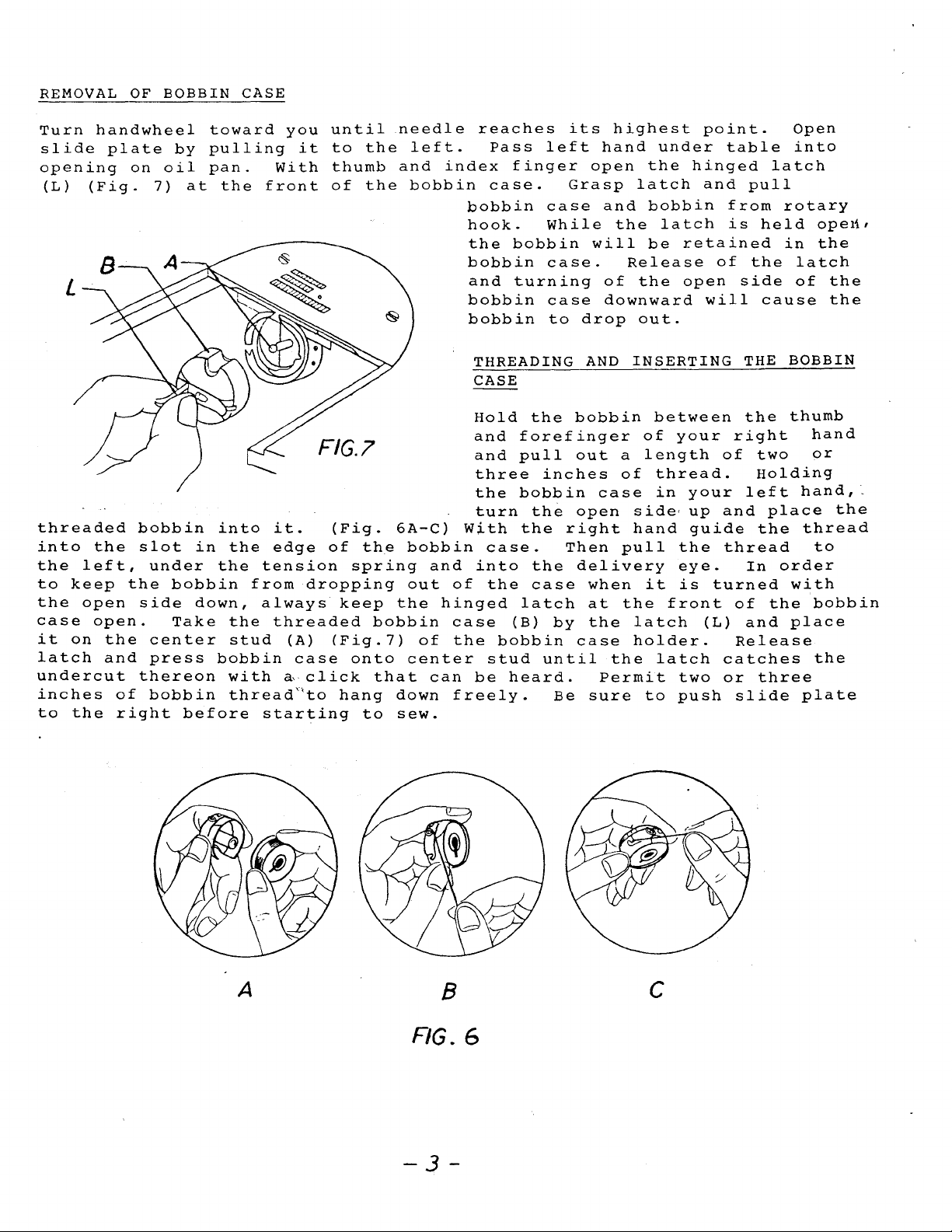
REMOVAL
OF
BOBBIN
CASE
Turn
slide
opening
(L)
(Fig.
threaded
into
the
left,
to
keep
the
open
case
it
on
latch
undercut
inches
to
the
handwheel
plate
on
7)
bobbin
the
slot
under
the
side
open.
the
center
and
press
thereon
of
bobbin
right
by
oil
at
in
bobbin
down,
Take
before
toward
pulling
pan.
the
into
the
the
from
the
stud
bobbin
with
thread''to
you
it
With
front
it.
edge
tension
dropping
always
threaded
(A)
case
~
click
starting
until
to
the
thumb
of
the
(Fig.
of
the
spring
keep
(Fig.7)
onto
hang
to
needle
left.
and
bobbin
6A-C)
bobbin
out
the
bobbin
center
that
down
sew.
and
of
can
reaches
Pass
index
case.
bobbin
hook.
the
bobbin
and
bobbin
bobbin
THREADING
CASE
Hold
and
and
three
the
turn
With
case.
into
of
the
hinged
case
the
bobbin
stud
be
freely.
left
finger
case
While
bobbin
case.
turning
case
to
the
forefinger
pull
inches
bobbin
the
the
the
case
latch
(B)
by
until
heard.
Be
its
hand
open
Grasp
and
will
of
downward
drop
AND
bobbin
out
case
open
right
Then
delivery
when
at
the
case
Permit
sure
highest
under
the
latch
bobbin
the
latch
be
Release
the
out.
INSERTING
between
of
a
length
of
thread.
in
side,
hand
pull
it
the
front
latch
holder.
the
latch
to
point.
hinged
and
retained
of
open
will
your
your
up
guide
the
eye.
is
turned
(L)
two
push
table
pull
from
is
held
the
side
cause
THE
the
right
of
two
Holding
left
and
the
thread
In
of
and
Release
catches
or
three
slide
Open
into
latch
rotary
in
latch
of
BOBBIN
thumb
hand,
place
thread
order
with
the
place
plate
opert•
the
the
the
hand
or
the
to
bobbin
the
A
8
RG.6
-3-
c
INSERTING
A
NEW
NEEDLE
Turn
point.
push
face
machine.
TO
Turn
moves
(bobbin)
and
in
handwheel
needle
toward
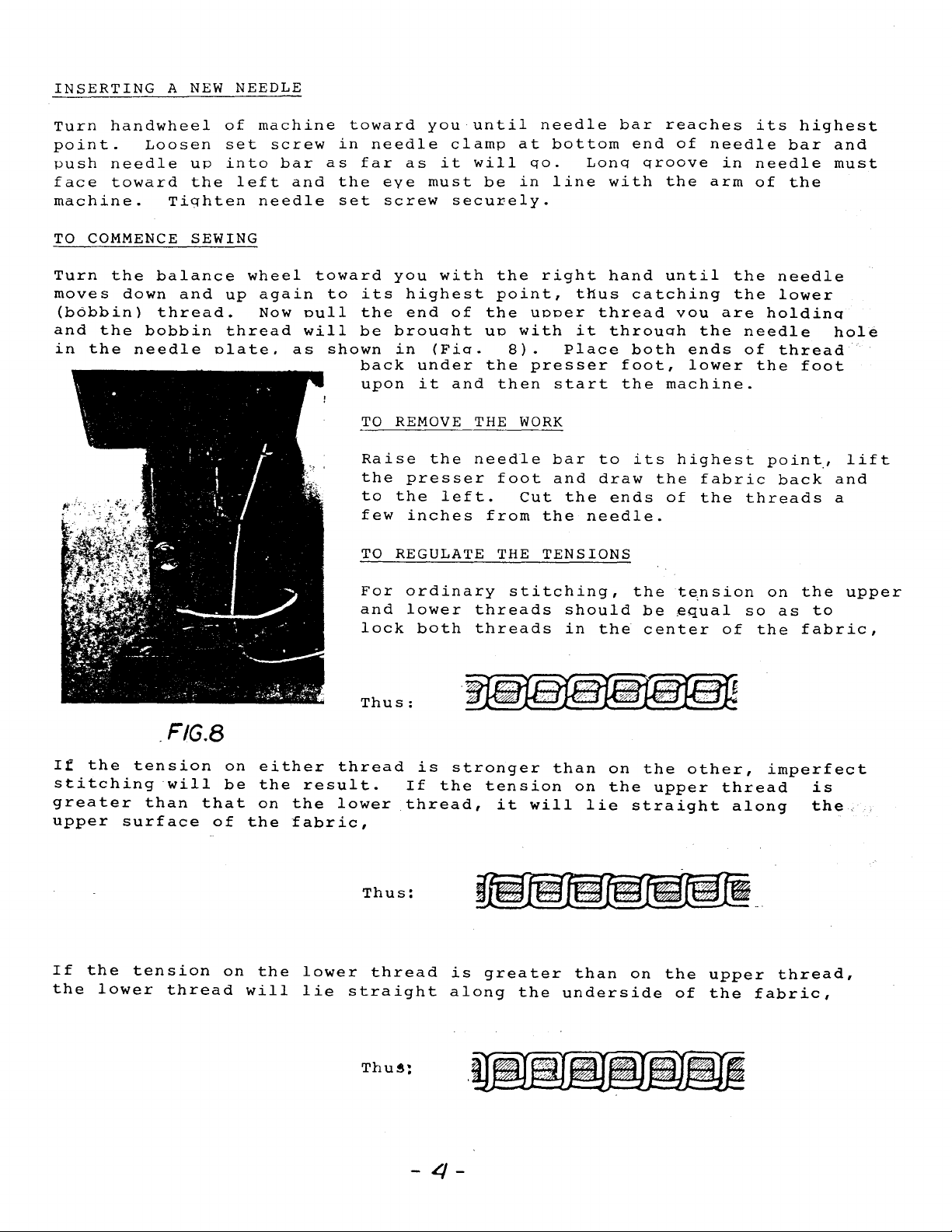
COMMENCE
the
the
the
Loosen
down
bobbin
needle
up
the
Tighten
SEWING
balance
and
thread.
of
set
into
left
wheel
up
thread
olate.
machine
screw
bar
and
needle
again
Now
null
will
as
toward
in
as
the
set
toward
to
shown
you
needle
far
as
it
eve
must
screw
its
the
be
back
upon
TO
Raise
the
to
few
TO
you
brouoht
with
highest
end
in
(Fio.
under
it
REMOVE
the
presser
the
left.
inches
REGULATE THE
until
clamp
will
be
securely.
the
point,
of
the
uo
8).
the
and
then
THE
needle
foot
from
needle
at
bottom
qo.
in
line
right
uooer
with
Place
presser
start
WORK
bar
and
Cut
the
the
TENSIONS
Lonq
with
hand
thus
thread
it
throuoh
to
draw
ends
needle.
bar
end
qroove
catching
both
foot,
the
its
the
reaches
of
needle
in
the
arm
until
vou
are
the
ends
lower
machine.
highest
fabric
of
the
its
needle
of
the
the
holdinq
needle
of
the
threads
highest
bar
the
needle
lower
thread
foot
point,
back
and
must
hole
lift
and
a
If
the
stitching
greater
upper
If
the
the
lower
.FIG.B
tension
will
than
surface
tension
thread
that
of
on
be
on
either
the
on
the
the
will
result.
the
fabric,
lower
lie
For
and
lock
Thus:
thread
lower
Thus:
thread
straight
ordinary
lower
both
is
stronger
If
the
thread,
is
along
stitching,
threads
threads
tension
it
will
~~~
greater
the
should
in
the
than
on
lie
than
underside
the
on
the
straight
on
t~nsion
be
~qual
center
the
upper
the
of
of
other,
thread
upper
the
so
the
along
-.
fabric,
on
the
as
to
fabric,
imperfect
is
the
thread,
upper
Thu~:
-
4-
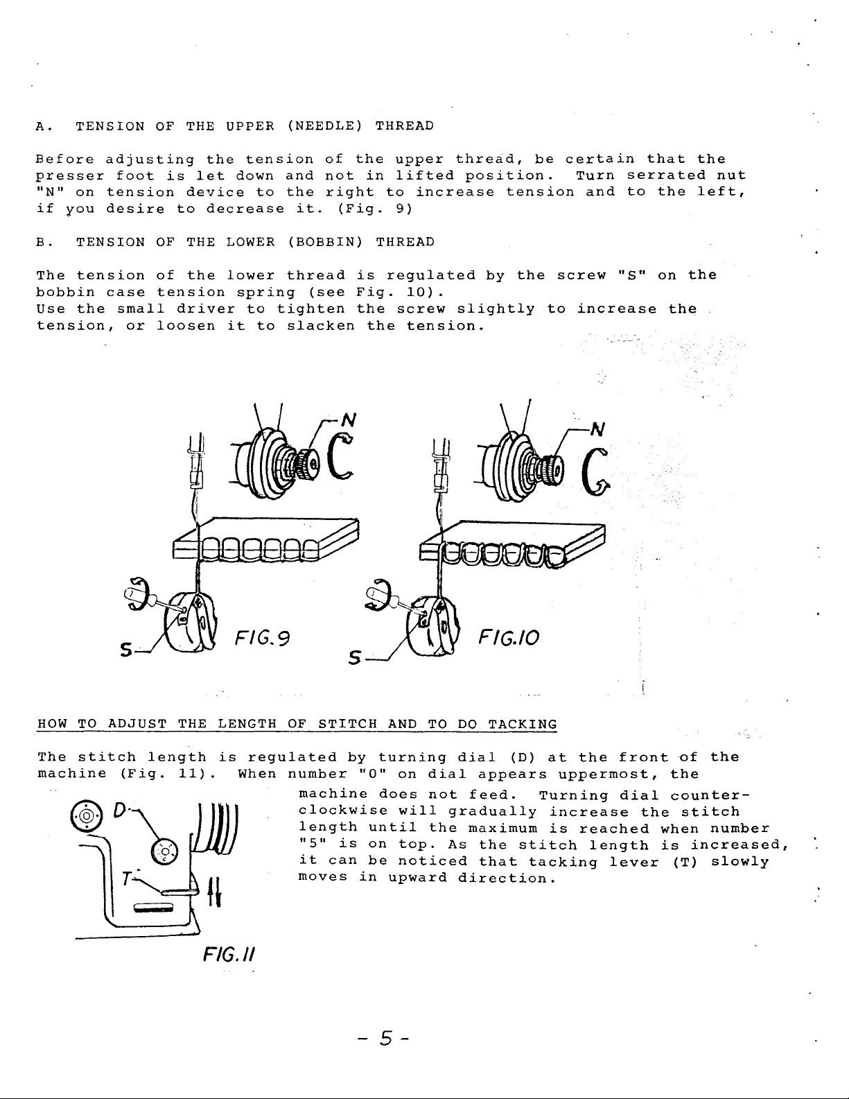
A.
TENSION
OF
THE UPPER (NEEDLE) THREAD
Before
presser
"N"
on
if
you
B.
TENSION
The
bobbin
tension
Use
the
tension,
adjusting
foot
tension
desire
OF
of
case
small
or
tension
loosen
is
device
to
THE
the
driver
the
let
down
decrease
LOWER
lower
spring
it
tension
and
to
the
thread
to
tighten
to
slacken
of
not
right
it.
(BOBBIN)
(Fig.
(see
the
in
THREAD
is
Fig.
the
the
upper
lifted
to
increase
9)
regulated
10).
screw
tension.
thread,
position.
by
slightly
be
tension
the
certain
screw
to
Turn
and
"S"
increase
N
that
serrated
to
the
on
the
the
nut
left,
the
HOW
TO
The
stitch
machine
5
FIG.9
ADJUST THE LENGTH
length
(Fig.
11).
is
When
regulated
FIG.//
OF
STITCH
number
machine
clockwise
length
"5"
it
can
moves
is
s
by
-
turning
''0"
does
until
on
be
in
5-
AND
TO
on
dial
not
will
the
top.
noticed
upward
F/G./0
DO
TACKING
dial
appears
feed.
gradually
maximum
As
the
that
direction.
(D)
stitch
tacking
at
the
uppermost,
Turning
increase
is
reached
front
dial
length
lever
the
~f
the
counter-
stitch
when
is
increased,
(T)
the
number
slowly
When
depress
To
depress
material.
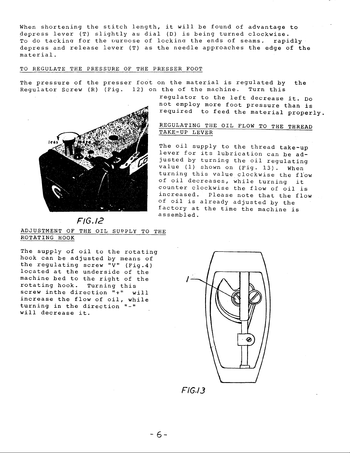
TO
The
Regulator
shortening
lever
do
tackino
and
REGULATE THE PRESSURE
pressure
Screw
(T)
for
release
of
the
the
(R)
stitch
slightly
the
ouroose
lever
presser
(Fig.
(T)
OF
length,
as
dial
of
as
THE
foot
12)
it
(D)
lockino
the
PRESSER
on
on
the
regulator
not
required
will
needle
the
of
employ
is
being
the
FOOT
material
the
be
found
turned
ends
approaches
machine.
to
the
more
to
feed
of
is
left
foot
of
advantage
clockwise.
seams,
the
regulated
Turn
decrease
pressure
the
material
rapidly
edge
this
of
by
it.
than
properly.
to
the
the
Do
is
F/G./2
ADJUSTMENT OF THE
can
inthe
HOOK
be
at
bed
hook.
the
in
of
oil
adjusted
the
to
direction
flow
the
direction
it.
screw
underside
the
ROTATING
The
supply
hook
the
regulating
located
machine
rotating
screw
increase
turning
will
decrease
OIL
to
right
Turning
of
SU~PLY
the
rotating
by
means
"V"
of
of
this
"+"
oil,
"-"
TO
(Fig.4)
the
the
will
while
REGULATING THE
TAKE-UP
The
oil
lever
justed
value
turning
of
counter
increased.
of
factory
assembled.
THE
of
for
(1)
oil
oil
LEVER
supply
its
by
turning
shown
this
decreases,
clockwise
Please
is
already
at
the
I
OIL
to
the
lubrication
the
on
value
while
the
adjusted
time
FLOW
(Fig.
clockwise
note
the
TO
thread
oil
turning
flow
that
machine
THE THREAD
take-up
can
be
regulating
13).
of
by
When
the
oil
the
the
ad-
flow
it
is
flow
is
F/G./3
-
6-
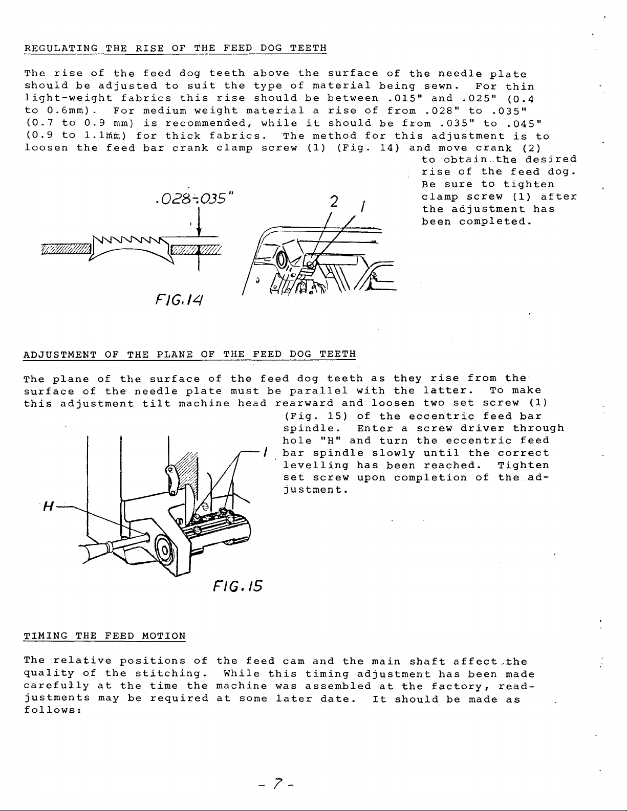
REGULATING THE
The
rise
should
light-weight
to
0.6rnrn).
(0.7
(0.9
loosen
to
to
of
be
0.9
l.lmm)
the
the
adjusted
For
rnrn)
feed
RISE
feed
fabrics
medium
is
for
bar
OF
THE FEED
dog
teeth
to
suit
this
recommended,
thick
crank
the
rise
weight
fabrics.
clamp
DOG
above
type
should
material
while
screw
.028~035"
FJG,
14
TEETH
the
of
be
it
The
surface
material
between
a
rise
should
method
(1)
2
(Fig.
of
for
I
of
being
.015"
from
be
this
14)
the
from
and
Be
been
needle
sewn.
and
.028"
adjustment
to
rise
clamp
the
.025"
to
.035"
move
obtain~the
of
sure
screw
adjustment
completed.
plate
For
.035"
to
crank
the
to
thin
(0.4
.045"
is
(2)
desired
feed
tighten
(1)
to
dog.
after
has
ADJUSTMENT OF THE PLANE
The
plane
surface
this
adjustment
of
of
the
the
surface
needle
tilt
plate
machine
H
TIMING
THE
FEED MOTION
OF
THE FEED
of
the
must
FIG.
head
IS
feed
be
rearward
spindle.
hole
I
bar
levelling
set
DOG
TEETH
dog
parallel
(Fig.
"H"
spindle
screw
justment.
teeth
and
15)
with
of
Enter
and
has
upon
as
they
the
loosen
the
turn
slowly
been
completion
rise
latter.
two
eccentric
a
screw
the
until
reached.
from
set
screw
feed
driver
eccentric
the
of
the
To
make
through
correct
Tighten
the
(1)
bar
feed
.ad-
The
relative
quality
carefully
justrnents
follows:
of
the
at
may
positions
stitching.
the
time
be
required
of
the
the
feed
While
machine
at
some
-
this
was
later
7-
earn
timing
assembled
and
date.
the
adjustment
main
at
It
shaft
the
should
affect-the
has
factory,
be
been
made
made
read-
as
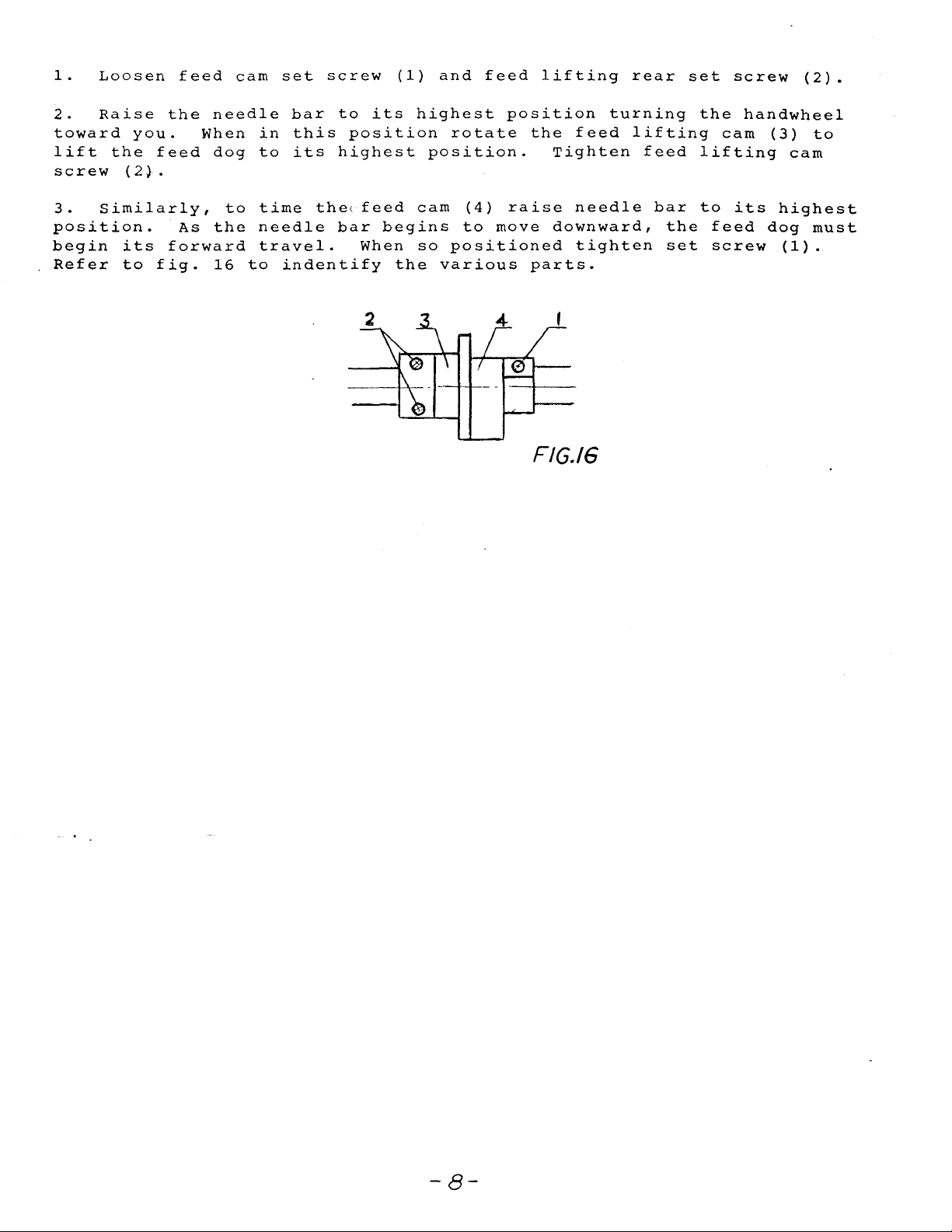
1.
Loosen
2.
Raise
toward
lift
screw
3.
Similarly,
position.
begin
Refer
the
(2).
its
to
you.
feed
fig.
feed
the
needle
When
dog
As
the
forward
16
to
cam
in
to
time
needle
travel.
to
set
screw
bar
indentify
this
its
to
highest
the(
bar
(1)
its
position
feed
begins
When
the
and
highest
rotate
position.
cam
so
positioned
various
(4)
to
feed
position
raise
move
lifting
the
feed
Tighten
needle
downward,
tighten
parts.
FIG./6
rear
turning
lifting
feed
bar
the
set
set
the
lifting
to
feed
screw
screw
handwheel
cam
its
dog
(2).
(3)
cam
highest
(1).
to
must
-8-
 Loading...