

Page 1

Page 2
------
To
get
the most
machine correctly.Please read this instruction Manual carefully before use.Whe hope you will enjoy the use
your machine for a long time.Please remember
1. Observe the basic safety measures,including, but not limited to
the
machine.
2. Read all the instructions,including,but not limited to this Instruction Manual before you use the machine.
In addition, keep this Instruction Manual
3.
Use
the machine after it has been ascertained that it conforms with safety rules/standards valid in your
Country.
4. All safety devices must be in position when
The
operation without the specified safety devices is not allowed.
5.
This
machine
6.
For your personal protection,
For
the following, turn off the power switch
receptacle.
7-1
For threading needle(s), iooper; spreader etc. And replacing bobbin.
7-2 For replacing part(s)
folder, cloth guide etc.
7-3
For
7-4
When leaving the working place
If
you should allow oil, grease, etc. used with
-er-s-k-~R--er-&vV-a+l-aw-an-y-a-f-s-o-ef-1-ltq'dict--b'1-·r-rh'8-t-a-ke-;-··-l-rrrm-e-diate-ly---wash--t'mn:
medical doctor.
--------
7.
8.
~--
out
of
shall be operated
repair work.
IMPORTANT
the many functions
by
appropriately-trained operators._
we
recommend
of
needle, presser foot, throat plate, looper,spreader, feed dog, needle guard,
or
SAFETY
of
this machine and operate
to
keep this manual in a safe place.
so
that
you may read it at
the
machine is ready for word
that
or
when
the
working place is unattended.
the
INSTRUCTIONS------
you
wear
disconnect the
machine and devices to
it
in safety,it is necessary to use this
the
following ones,whenever you use
anytime
safety glasses.
power
plug
when necessary.
or
in operation.
of
the machine from the
come
in contact with your eyes
..
uT,ta-c'reti-areasam:i----corrsuih:l-···
of
9.
Tampering with the live parts and devices, regardless
10.
Repc1irl
specially skilled personnel. Only spare parts designated by can be
11. General maintenance and inspection works have to be done
12. Repair and maint~n~nc;e works
technicians
Whenever
13. Before making repair and maintenance
an air cylinder,
has to be
has to be
appropriateiy
14. Periodically
15. Grounding the machine is always necessary
to be operated in an environment that is free from strong noise sources such
16. An appropriate power plug has to be attached to the machine by eledtric technicians. Power plug has to
be commected to a grounded receptacle.
17.
The
18. Remodel
effective
of
19. Warning hints are marked with the two shown symbols.
remodeling and adjustment works
of
electrical components shall be conducted by qualified electric
or
under
·the audit and guidance
you find a failur-e
the
air compressor has
cut
off. Existing residual air pressure after disconnecting
expelled.
trained technicians or specially skilled personnel.
clean the machine thrqughout
machine is only allowed to be used for the purpose intended.
or
modify the machine in accordance with the safely rules/standards while taking
the
machine.
safety
measures.
of
any
Exceptions
assumes
of
electrical components, immediately stop the machine.
to
must
of
specially skilled personnel.
works
on
to
be detached from the
this
are
only
the
period
for
no
respqnsibility
of
whether
only be done
the
machine
adjustments
of
use.
the normal operation
for
the
by
appropriately trainde technicians
used
by appropriately trained personnel.
equipped
machine
the
and
Other
damage
machine
for
air
of
used are not allowed.
by
is powered, is prohibited.
repairs.
with
pneumatic
and the compressed air supply
compressor from
performance
the
machine.
as
high-freauer1cy welder.
remodeling
parts such as
the
checks
The
machine has
an
or
modification
machine
done
the
by
or
Danger
Items requlring
of
injury to operator
special attention
or
service staff
ii
Page 3
CAUTION
1.
fo
avoid electrical
motor
the
1.
To
avoid personal injury, never operate the
Finger guard
2.
To
prevent
Keep
motor
3.
To
avoid
'[ON" the
4.
To
avoid
while the
5.
The
hook
posslb!e
the
hook
machine
6.
To
avoid
nor touch the
possible
your
fingers,
while the
personal
power
personal
machine
rotates
injury
during
when
possible
------r-nae-hfne-w-h-e-n-t-Ht-l-n-g/-ra-i-3-i-n
7.
To
avoid possible
power
to the
shock
or
safety devices removed.
machine
injury, never put
switch
injury, never put
is in operation.
at
to
hands,
operation.
replacing
personal
accidents
machine
hazards,
components
personal
head
and clothes
is operation, In addition, place nothing
or
a high
the
when
injuriescaused
operate
speed
be
sure
In addition, be
bobbin.
injuries,be
-th-e--m-a-eh-i-ne-h-e-a-cl
9
because
tilting the
neither
the
while the
to
open
mounted
away
your
hand
machine.
your
beep
careful
of
abrupt
machine
the
cover
inside the electrical box.
machine
by
being caught in
from
the
under
fingers
machine
your
sure
hands
to
not
·:
start
head.
into
--· - -- ------
of
the
with
any
of
handwheel, V belt
the
needle
the
thread
is in operation.
away
from
turn
OFF
to allow
your
- ·
of
the machine,
electrical
the
belt
the
around
when
take-up
the
the
power
fingers
turn
box for
cover,
machine,
and
the
them.
you turn
cover
To
prevent
vicinity
to
in
the
OFF
of
the
the
8. If
your
machine is
while the machine is at rest.
machine, be
9.
To
avoid electrical
ground wire for the
10.
To
prevent
components(s),
of
the
sure
possible
power plug.
[_s_E_F_O_R_E_O_P_E_R_A_T_IO_N
equipped
to
turn
shock
power
accidents
turn OFF the power switch in prior to the connection/disconnection
with a servo-motor,
To
avoid
possible
OFF
the
power
hazards, never operate
suppiy removed.
because
to
the
of
accidents
electric
the
motor
machine.
the
aewing
shock
does
due
machine
or
not
produce
to
abrupt
damaged
________________
Ii\ CAUTION:
~
• Before you put the machine into operation for the first time after the set up, clean it thoroughly.
• Remove all dust gathering during transportation and oil it well.
• Confirm that the power plug has been properly connected to the power supply.
• Never use the machine in the state where the voltage type
• The direction
side. Be careful not to rotate it in reverse direction.
of
rotation
To
avoid malfunction and damage
of
the sewing machine
of
the machine, confirm the following.
is
different from the designated one.
is
counterclockwise as observed from the handwheel
start
with
electrical
of
the
noise
the
J
iv
Page 4
Consew
7360R-
7DD
series
CONTENTS
♦
INSTRUCTION MANUAL
1.
SPECIFICATIONS ........................................................................................................................ 1
2. INSTALLATION ............................................................................................................................. 1
3. ADJUSTING
4. INSTALLING
5. LUBRICATE ................................................................................................................................. 3
6. LUBRICATION ............................................................................................................................... 3
7. ADJUSTING
8. ATTACHING
9. SETTING
10. ADJUSTING THE STITCH LENGTH ............................................................................................. 6
11.
PRESSER
12. HAND LIFTER ............................................................................................................................... 6
13. ADJUSTING
14. THREADING
15. THREAD TENSION ....................................................................................................................... 8
1·6.
THREAD' TARE~·up·
17. ADU STING THE THREAD TAKE-UP STROKE ............................................................................ 9
18. NEEDLE-TO-HOOK RELATIONSHIP ........................................................................................... 9
19. HEIGHT
20. TILT
21. ADJUSTING
22. ADJUSTMENT
23. PEDAL OPERATION ...................................................................................................................
24. ONE-TOUCH TYPE REVERSE FEED STITCHING MECHANISM .......................................... 13
25.
26. DISASSEMBLING OF OPERATION PANEL .............................................................................
OF
ELECTRONIC
THE
HEIGHT OF THE KNEE LIFTER ..................................................................... 2
THE
THREAD STAND ............................................................................................. 3
THE
AMOUNT OF OIL(OIL SPLASHES) IN THE
THE
NEEDLE ............................................................................................................ 5
THE
BOBBIN INTO THE BOBBIN CASE ..................................................................... 6
FOOT
OF
THE
PRESSURE ...................................................................................................... 6
THE
HEIGHT
THE
MACHINE HEAD ............................................................................................. 7
·sPR-ING
THE
FEED DOG .....................................................................................................
FEED DOG ............................................................................................................
THE
FEED TIMING .................................................................................................
OF
THE PEDAL ..................................................................................................
CLIP
OF
THE PRESSER BAR ................................................................... 7
.......................................................................................................... 8
WIRE.
..
................................................................................................. 13
HOOK
......................................... 4
10
10
11
12
12
14
♦
PARTS BOOK
1. MACHINE FRAME & MISCELLANEOUS COVER COMPONENTS ....................................... 17-20
2.
MAIN
SHAFT
3.
NEEDLE BAR.UPRIGHT SHAFT&HOOK DRIVING SHAFT COMPONENTS ....................... 23-24
4. HAND LIFTER COMPONENTS .............................................................................................. 25-26
5. FEED MECHANISM COMPONENTS .................................................................................... 27-30
6. THREAD
& THREAD-UP LEVER COMPONENTS .......................................................... 21-22
TRIMMER
COMPONENTS .................................................................................... 31-32
7. AUTOMATIC REVERSE FEED COMPONENTS .................................................................... 33-34
8.
ELECTRONIC
9. OIL LU
10.
OIL.
11. THREAD STAND COMPONENTS .......................................................................................... 37-38
BU
RESERVOIR COMPONENTS .......................................................................................... 35-36
CONDUCTOR
CATION COMPONENTS ........................................................................................ 35-36
HOLDER
NEEDLE
SELECTION
BOX
COMPONENTS
............... 33-34
12. ACCESSORIES ...................................................................................................................... 37-38
contents
Page 5
1.
Model
Application
Sewing speed
Max.
Stitch length
Needle
Presser
lubricating
Noise
foot
lift
oil
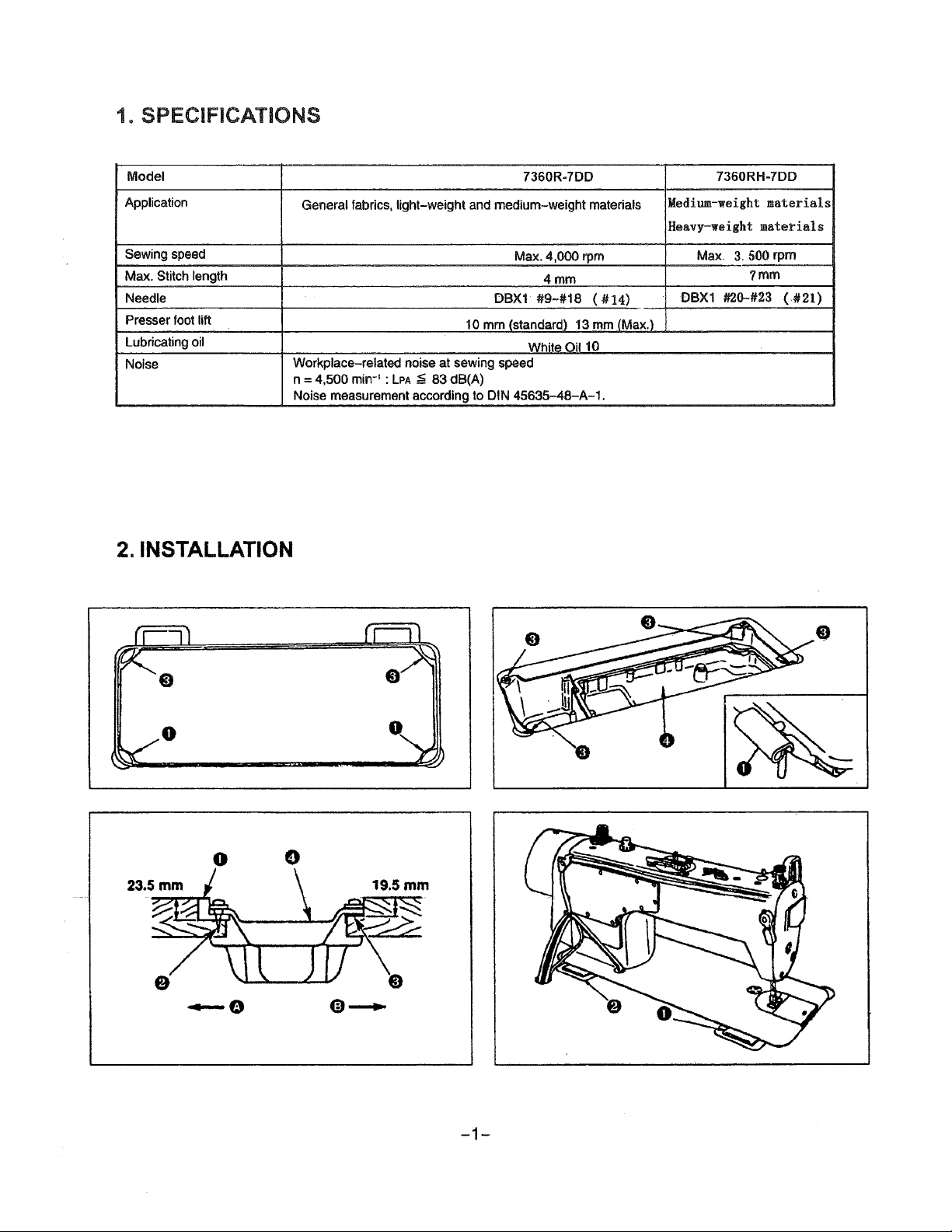
2. INSTALLATION
7360R-7DD
General fabrics, light-weight and medium-weight materials
1 o mm (standard) 13 mm (Max.)
Workplace-related noise at sewing
n = 4,500 min-
Noise measurement according
1
:
LPA
~
83 dB(A)
to
Max. 4,000
DBX1
White Oil
speed
DIN 45635-48-A-1.
4mm
#9-#18
rpm
(
10
#14)
7360RH-7DD
Medium-weight
Heavy-weight
Max.
3.
500 rpm
DBX1
#20-#23
materials
materials
1mm
(.#21)
0
0
0
-1-
Page 6
{1) Bnstamng
1)
The
2)
Fix two rnbber seats O on
E) on side (D (hinged side) using a rubber-based adhesive. Then place oil
3}
Fit hinge 8 into the opening in the machine bed, and fit the machine head to table rubber
placing the machine head
3s
~~~fF~
oil
the
pem
should rest
t\ia{J~~
under
cover
on
the four corners
sicteO(operator's
on
cushions
of
the machine table groove.
side) using
6)
on the
four
comers.
nailsf)as
I ADJUSTING THE HEIGHT
illustrated above. Fix
pan8
on
OF
THE. KNEE LIFTER
t:wo
the fixed seats.
cushion seats
hinge@
it~
~7M~•*~&~8d~-~-~N*
WARNING:
Tum
OFF
sewing machine.
____
L)
__
~jf¾.fHJ~Lffi
2)
ijJ'f1"~i;JJ~3t-~-=p-~!!
the
power
before
starting
JWl}_il.fE_i\%_~
....
iJHlmm-0---- _
8PJWJE.ffiijt4J~~~.fdftiJ~Jtil3mmo
the
__
■
work
fimflo
so
as
to
prevent accidents caused
0
___
(
A~&rit:kn9mmo
_
______________________________________
by
abrupt
.,_
___
)
start
_
_
3)ffi~-*~1omm~k~.-~•ttff8~~~T~~-~T~,~-m~lli~80
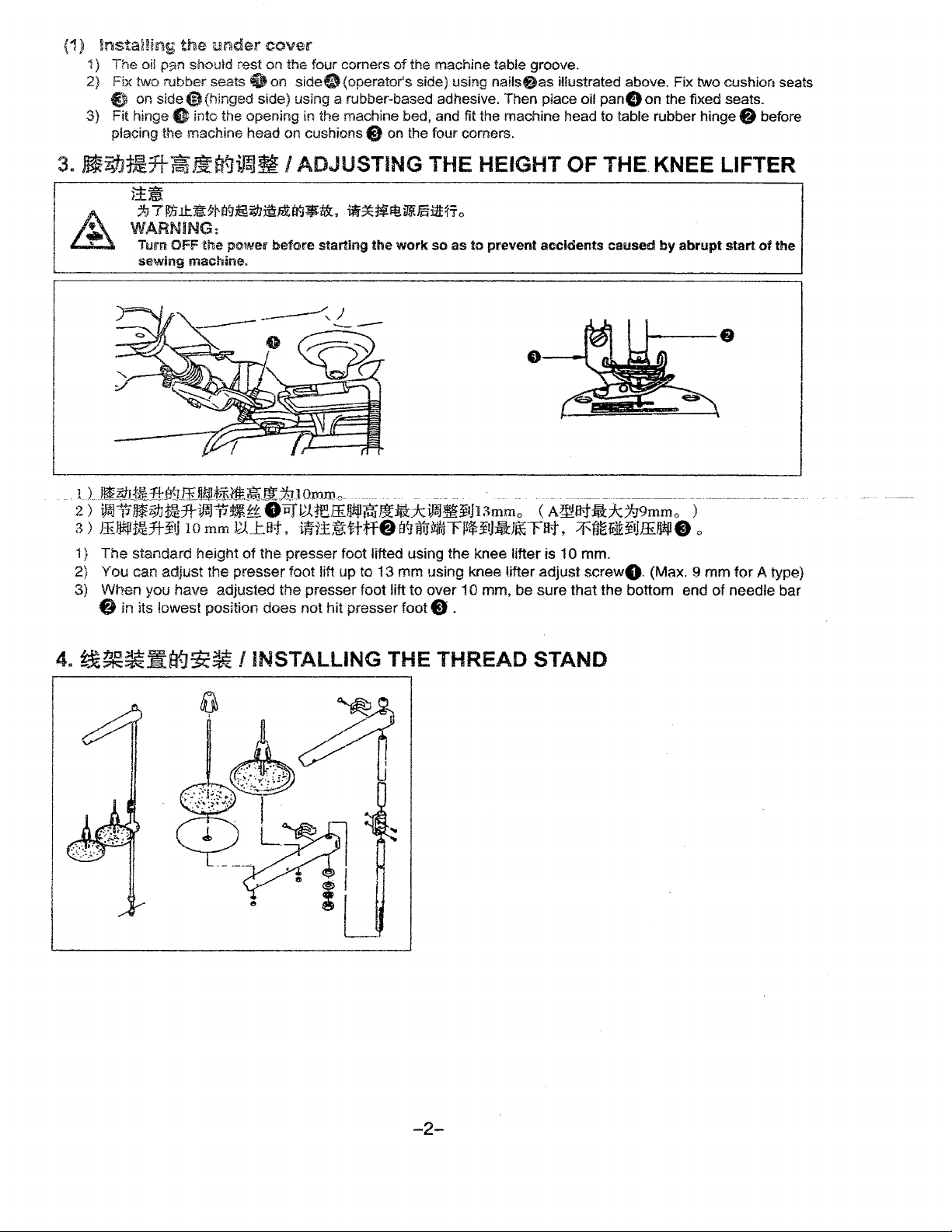
1)
The standard height of the presser foot lifted using the knee lifter is 1 O mm.
2)
You can adjust the presser foot lift up to 13 mm using knee lifter
3) When you have adjusted the presser foot lift to over 1 O mm, be sure that the bottom end of needle bar
8 in its lowest position does not hit presser foot C, .
adjust
screw8. {Max. 9 mm for A type)
before
of
the
-2-
Page 7
Turn OFF
sewing machine.
the
power before starting
the
work
so as
to
prevent
l )
il~fl;p~tJ~~~fffflO
rJ~~~ff ffi o
accidents
B{J
/J\fL
caused
_ta{J/J"!illtr
11-J
o
Fo,
~j(ijffi-ij~tl:i~
start
2>•~fiTttff~mttm~Fo-~ttff~mtte.1.oo~
•n,
~Mffl-nl~tl:i~Hff~~tt
lr-yJ,fL~
of
the
o
6.
1JIHW
I LUBRICATION
j!~
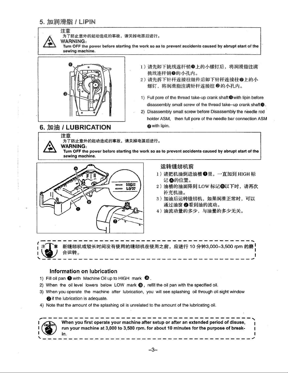
1) Full pore of the thread take-up crank
disassembly small screw of the thread
2) Disassembly small
holder ASM, then full pore of the needle
9with
lipin.
screw-before Dis-assembly the needle rod ·
shaftOwith
~7•~-#~~~-~~•-,•~N-~~mfio
WARNING:
Turn OFF the power before starting
sewing machine.
the
work so as to prevent accidents caused by abrupt start
m~~;,JJtJUtr
1)
ifHf'.tJLnb{itl:ittnb:ffN
811L
~
ic0891:V:~o
2)
nbffis{Jnblffi~J~
Low
t~icCD~.rFat,
~H:tt:tJLhBo
3)~nh~~~•wm,~•Mm-~nat,ey~
Ji.~ntJTM
4)nb~l9J-~~~,~ntJ•s{J~~x*o
Oifi~ilbaqvftigj
o
take-up
bar
connection ASM
1[1JOJ~
HIGH
lipin before
crank
shaft9
of
the
fj
i1i-NIX
.
~-----------------------------------~---~
f
{iji±
ii
tfr~~JWlrot~*B-tfsJ5j:1if-fiEJ:JHt~tif~JJffi.tt-fifflZwJ,
I
A•-t:
1=1
'IA~~ o I
Eilnrfi-
10
~tqt3,000~3,500
'------------------------------~---------~
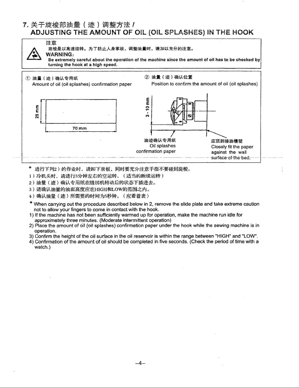
Information on lubrication
1) Fill oil pan 8 with Machine Oil up to
2) When the oil level lowers below LOW mark
3) When
4) Note that the amount of the splashing oil is unrelated to the amount of the lubricating oil.
,----------------------------------------~
I (I) When
I
I , in. I
you
operate the machine after lubrication, you will see splashing oil through oil sight window
8
if
the lubrication is adequate.
you
first
run
your
machine at 3,000
operate
'-----------------·
HIGH
mark
0)
your
machine after setup
to
3,500 rpm.
----------------------~
f.b
.
, refill the oil pan with the specified oil.
or
after an extended period
for
about 10
mintl.lltes
for
the purpose
-3-
of
of
rpm
a9J!
disuse, I
break- 1
1
I
Page 8
7.
*-rME~if~jf.E;;_
ADJUSTING
)±~
A :tdi~~
~
CD
WARNING:
iitl:R
(
i2! ) ?imi..A.
Amount
!
[i------
~:,i
Be
extremely
turning
the
-:ti
of
oil (oil splashes) confirmation. paper
THE
iti
~mtt
careful
hook
ffl~
_
70mm
(
~
)
ifaJ~:tf5*
AMOUNT
o
7-J 7 fIJJ
.tl:..A..
about
the
at a high
speed.
OF
Ji½
•t&,
operation
iJfJ
____,
/
OIL
{OIL
~im :lta-t,
of
the
machine
@
E
E
0
,..
.
(">
SPLASHES)
ii
nn
~
1t
,-h¥.H±~
since
im:Ji
(
iW!
)
iiffii-A
Position to confirm the amount
the
fil:lt
o
amount
of
IN
oil
THE
has
HOOK
to
be
checked
of
oil (oil splashes)
by
imi2l!i'Mi-A
Oil splashes
confirmation paper
-------
-----· -------
-----------
* .i!!fr~1~2 )
l ) ,ttJL~B;j,
2 )
ilh:!i
3 )
iffiiffiAnbili¥-Jnbffii~~Mt£HIGH~LOWEY-Jm:l:m~~l
4)
~i-Arru:it
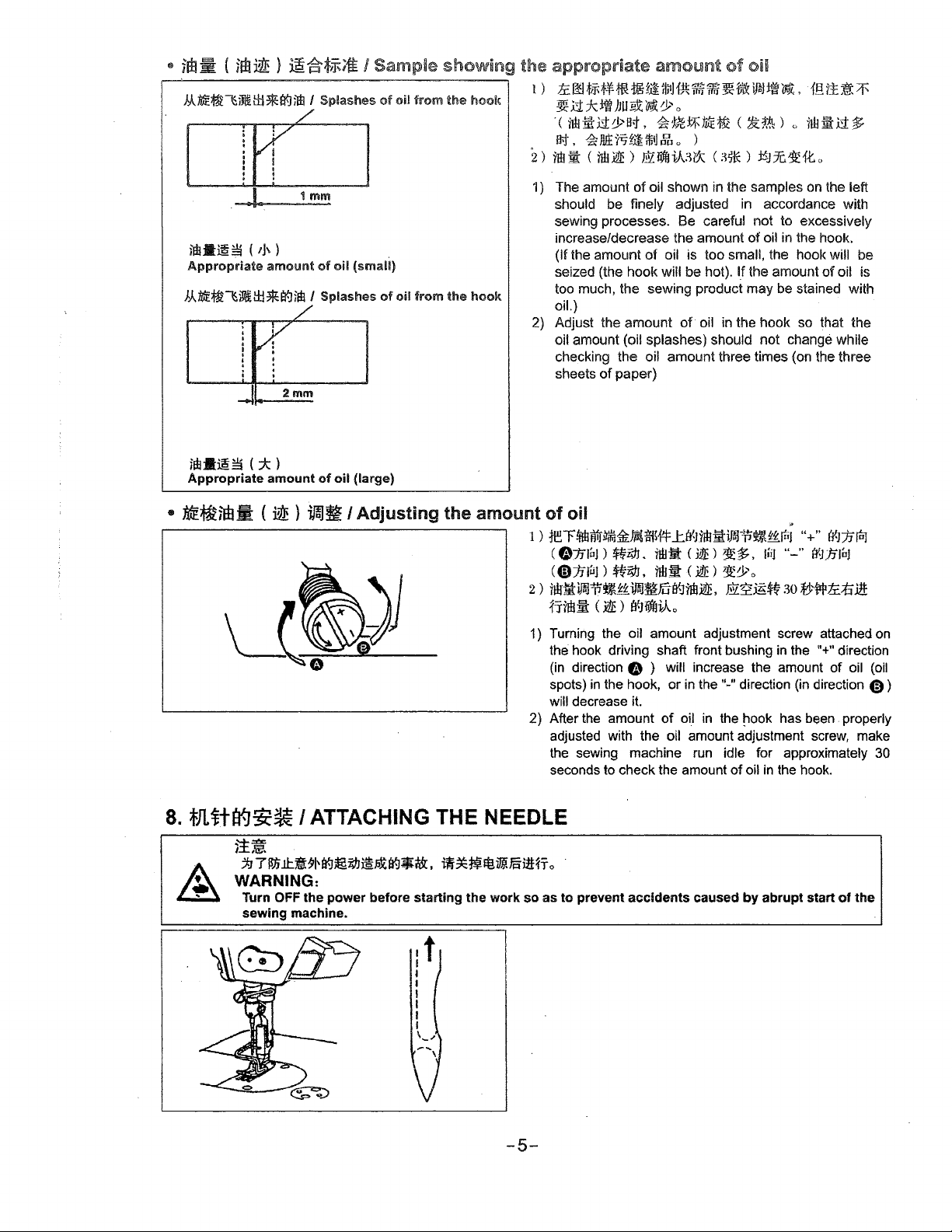
* When carrying
not to allow
If
the
1)
approximately three minutes. (Moderate intermittent operation)
2)
Place the
operation.
3) Confirm the height
4)
Confirmation
watch.)
B'-11'1:~at.
~i:itt1iMtl1flic.tiEF-J~.6~(,
(
3dE
) iffliA-tf-JH~Miii3Jffl~;tJJciatf~~rM31r* o
()Qt)
EJr1Rr~~Htfe)7-15f'P~o
out
your
fingers
machine has
amount
of
the
t1tmrflt;fii, ~at~1EtHi:~¥m~~ittitlnte1Jt,
(
m~e'~~~-6~)
( EY~ff*)
the procedure described below in 2, remove the slide plate and take extreme caution
to
come
in contact with
not
been sufficiently warmed
of
oil
(oil splashes) confirmation
of
the
oil surface in the oil reservoir is within the range between "HIGH"
amount
of
oil should be completed in five seconds. (Check the period
o
the
hook.
up
for operation,
paper
~
ffl~
under
mlffiitltiiJHtl~
Closely fit the paper
--------------s-ti-rl-aee--cHhe-be-d-.---
make
the machine run idle
the
hook
white the sewing machine is in
against the wall
of
for
and
"LOW".
time with a
______
T
___
-
-4-
Page 9
•
im ~ (
hA.ttff~~~l±l*a{]im
)W-~~
Appropriate
im ~ )
( ,J,)
amount
~~tj;-ft
I Splashes
1 mm
of
oil
J..Atdt~~~tf:l*a{]jfil I Splashes
2mm
/ Sample showing the appropriate amount of oil
1)
of
(small)
of
oil
oil
from
from
the
the
hook
hook
ftoo~~m~~~~~~~~~~~.m~~~
~.u::k:lft
. (
11H
IJ;J,
2)
rmm
1)
The amount
should be finely adjusted in accordance with
sewing processes. Be careful not to excessively
increase/decrease the amount of oil in the hook.
(If the amount
seized (the hook will be hot).
too much, the sewing product may be stained with
oil.)
2)
Adjust the amount of- oil
oil amount (oil splashes) should not
checking the oil amount three times (on the three
sheets
)JUliX:~0>
ill
.ct
0>
B;j-
~
Jlltt5t.i1ffi!J
c
¥1ff
JQ'E)
of
paper)
0
,
~
'.l;?t
~
ME
it&
( ~ t& ) ()
g O )
~liffj-j,,A~,x
of
oil shown in the samples
of
oil is too small, the hook will be
c
~*)
l_f
in
the hook so that the
ilH
~Jx.~fto
on
the amount
change while
ii
.u
the left
of
oil is
$
im•~~
Appropriate amount of oil (large)
•
ME~im:m:
( * l
(
~ ) ~~
/
Adjusting
the
amount
1 )
of
rer~tr«irJ1Jmfi'i~tr1Wt=
(
01.ilnJ
C«D:nruJ)
2 >
rlkltl)lJ,'rij{~iiJiJ~FuB'1'imi2E,
frnll
1) Turning the oil amount adjustment screw attached
the hook driving shaft front bushing
(in direction
spots)
will decrease it.
2) After the amount
adjusted with the oil amount adjustment screw, make
the sewing machine run idle for approximately
seconds to check the amount
8. *llita{J~~ I ATTACHING THE NEEDLE
}±~
·~
, WARNING:
•
j;j71Jjjll:.~9~f,J~WJ1§~r-J•tt.
Turn
OFF
sewing machine.
the power before starting the work so as
-tff~Hf~vi.lEiiltJro
oil "
..tB'1nai!:iJWn~~t
)
~igj.
rwiit
<
.i1E)
1t~,
,,iJ
~zYJ,
11Bll'
<
JdE)
~:Po
m:~~~
:m:
(
.i1E
>
tr-J
iifffi-A
o
O ) will increase the amount of oil
in
the hook, or
to
prevent accidents caused
of
in
the"-"
direction
oi_l
in
the ~ook has been. properly
of
oil
in
by
abrupt start
rt1
"+"
t't1Jiful
.. _ ..
EY-J.fflnJ
30 tY~ti.;tiilt:
11
in
the
+"
direction
(in
direction
the hook.
of
on
(oil
C,)
30
the
,t
I
I
I
I
I
I
I
\_.,
-5-
Page 10
g_
~1t\og~~1nt I SETTING THE
BOBBIN
INTO THE
BOBBIN
CASE
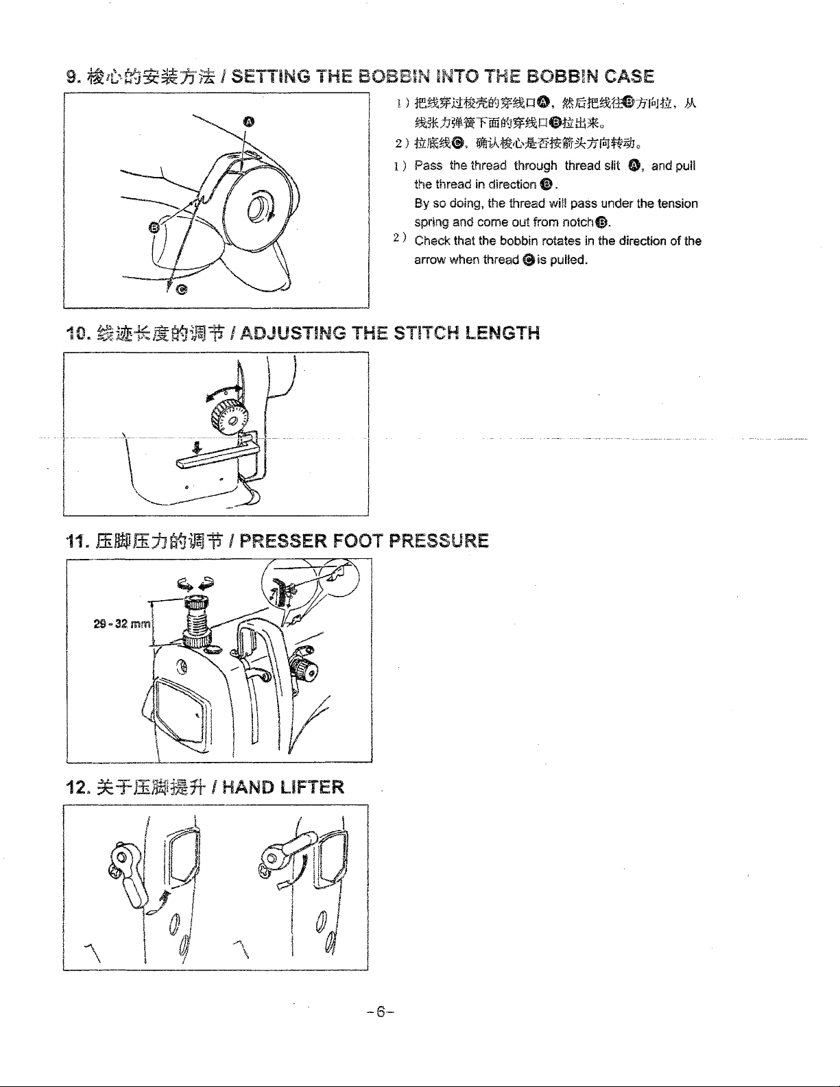
1 ) re~~;1~~rt-J~~PO.
~s*h5ltl
2)
t.v:r~~@.
1)
Pass the thread through thread slit
the thread in direction 8 .
By
spring and come out from notch@.
2
) Check that the bobbin rotates in the direction
arrow when thread
10. ~~tEJ~agi~"ii I ADJUSTING THE STITCH LENGTH
,\•
''"
~
OJ
-• -••••+•••-•-••H
\
IJ
.
ti
iffoo
1iJfri-,A~,t.--¾tHi~~1ftoJtti9Jo
so doing, the thread
\"--
?&Fure~M»:nruJtiL,
1¥-J~t%o@Ht:
$is
tiB~o
wm
pass under the tension
pulled.
ti,
JA
and pull
of
the
11·.
ffifft.Pl.:b.:ha{J~,t I PRESSER FOOT PRESSURE
/d
~,.,111
~a
0 I
-,
al
\
-~r
If f
~
I
@
I
-6-
Page 11
13.
ffiOOff~Jla{Ji)aj~
~·
;1:JTm~•*~~~@-~-~.-~-~Bfilmfto
WARNING:
Tum
OFF
sewing
the
machine.
I ADJUSTING THE HEIGHT OF THE PRESSER BAR
power
before
starting
the
work
so
as
to
prevent
1)
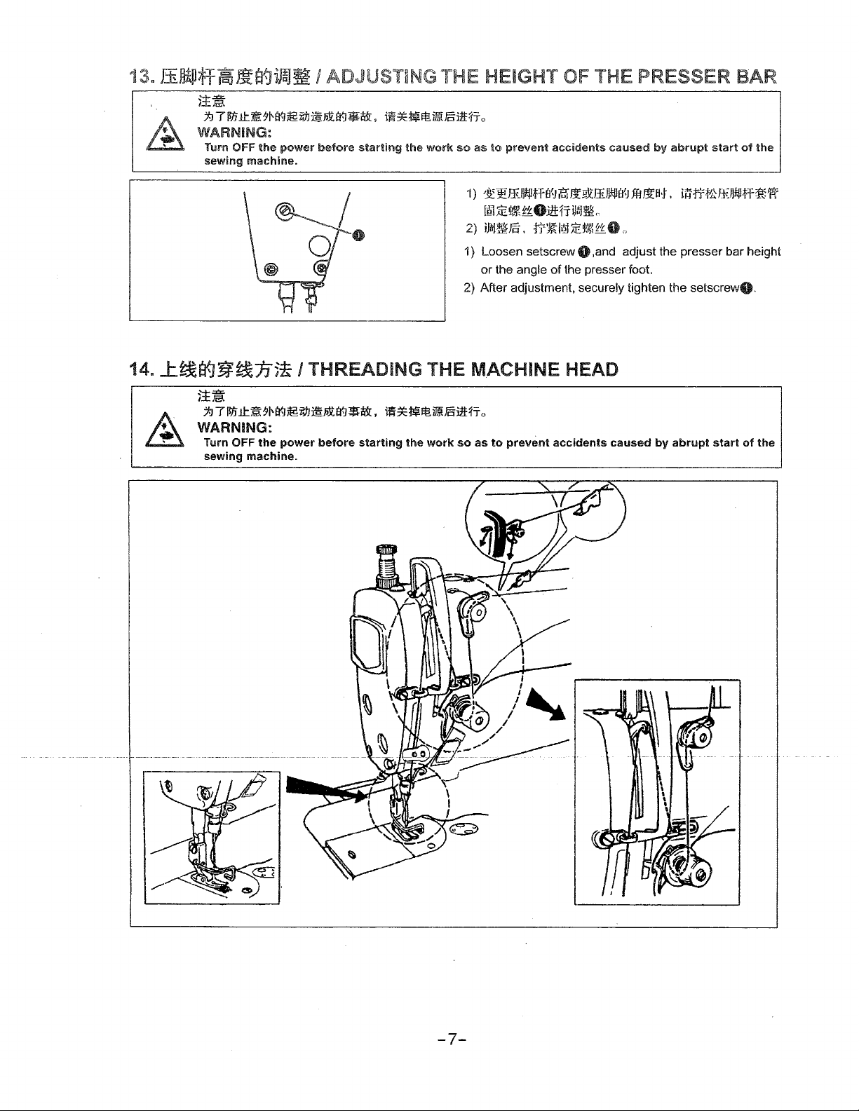
~~ffi.f}!jlffa{J7$ijOocffiJJkl]B'~fl=J~M.
accidents
caused
!i!'lm:~t~Oilf:f=rU~f&"
2)
iJMm€.
1) Loosen setscrew O ,and adjust the presser bar height
or the angle of
2) After adjustment, securely tighten the setscrewO.
tr~l~~~~~O"
the
presser foot.
14. 1:~a{J~~JJ51 I THREADING THE MACHINE HEAD
j!~
;/:J
TM"1J:JUHr-J~~m-tr-J$i&,
WARNING:
Tum
OFF
the
power
sewing
machine.
before
iU~J~~~mmfi-o
starting
the
work
so
as
to
prevent
accidents
caused
by
abrupt
start
itrtrt-'Jlt-]!ilH~~
by
abrupt
start
of
of
the
the
/
/'
-·-
~--•-.s•--•
---------·
-7-
Page 12
15.
~~*:h~
I
THREAD
TENSION
( 1 ) J:~s-itn
1)
luJtrG
tEtllH
2 )
fPJtr:tD
3 >
fuJ
~Ha.:.
4)
ruJti.
( 2 )
~~5f
1 )
rt1:tt@
2)
1tJt:c.O
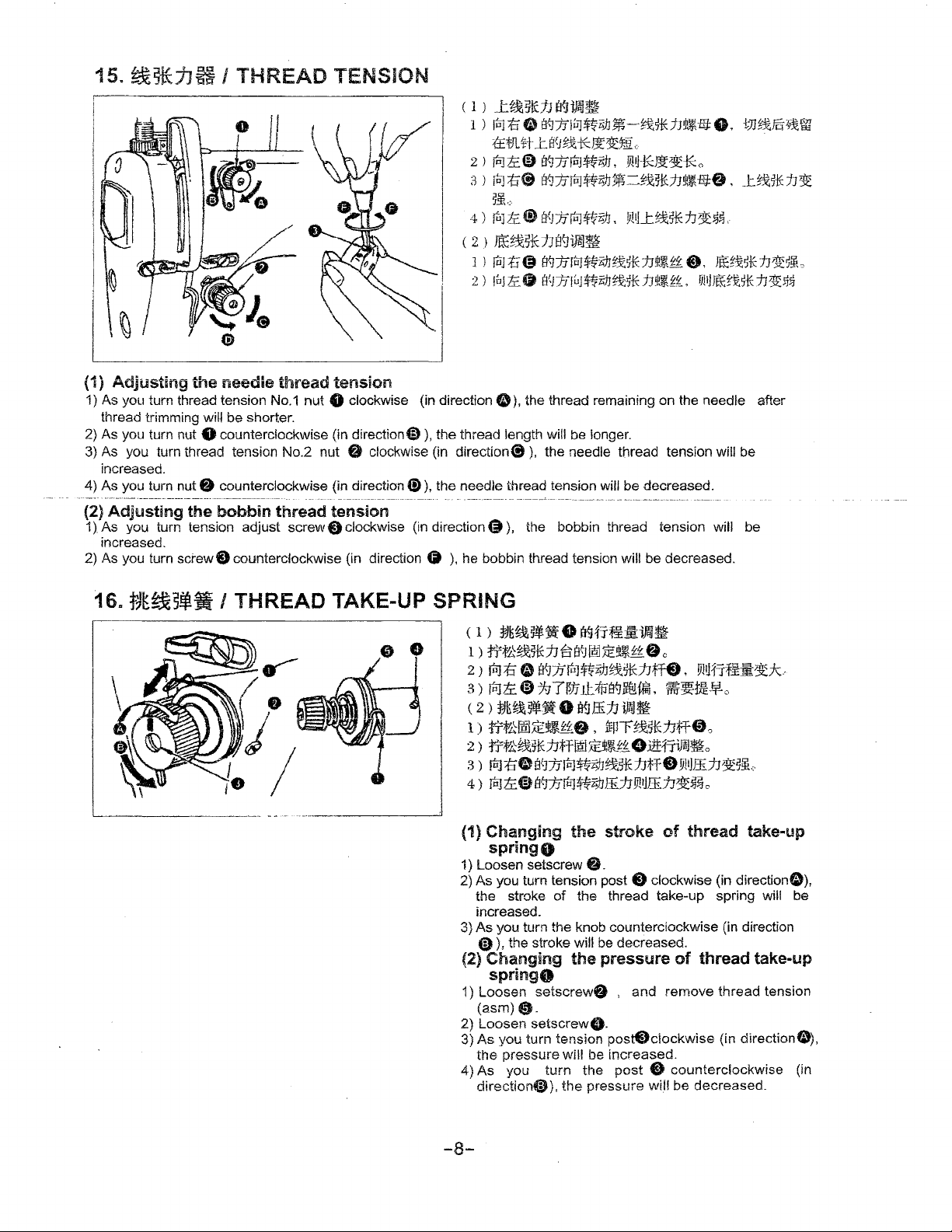
(1)
Adjusting
1) As you turn thread tension No.1 nut 8 clockwise (in direction O
thread trimming
2) As you turn nut
3) As you
increased.
4) As you
- - . -
(2)
1).
2) As you turn
----------·----•------------·····----
Adjusting
As you turn tension adjust
increased.
the
needle
wiU
be
thread
shorter.
tension
8 counterclockwise (in direction@)), the thread length will be longer.
tum
thread tension No.2 nut O clockwise (in
turn nut O counterclockwise (in direction(!)), the needle thread tension will be decreased.
the
bobbin
screw9
counterclockwise (in direction O
----------------------------------------------
thread
screw&
tension
clockwise (in
direction(!)),
-
----------~----
direction~),
),
he bobbin thread tension will be decreased.
a{J]ij]~
B'.JJJlu1$¼iJJ~--~t5-IUJ!Pl-E;J:0,
J:.s{Jt~*1Jr~~1L
B{J7Jfn]~iJJ,
1:18
BkJ::iJfoJ!t~zifl~=§'~8-lth!Pl-E;J:0
®
s<Jn(u1$~iJJ,
::1J
89-iftu~
s~nrtJ$tRJJristE:fJ!l'J£t
sZ1frruJ$~iJJ~stEJJ!11Ji~,
),
the thread remaining on the needle after
the needle thread tension will be
the bobbin thread tension will be
WU*J3t~-ff:o
,
vrn_t~5-!E:fJ1t~t
e,
ntEttstE1J~5lL
m1JJ!tE~s-lf:n1t~ScJ
---•--·----·--
tJJt%€fl'fil
_UM~
1J1t
16m
tJK~s-'ti
/ THREAD TAKE-UP SPRING
< 1 )
~~~~•
..,--
f)
I
I
0 •
1 )
trt0~s-K:1J ~ a~
2 >
roJti
3)
foJtc@>
<
2)
};J~~stif
1)
rrt'llmJEtJ~f'.8, ffPT~1*1Jff0"
2 )
rrtl4%sKfJH!Et1
3 )
!oJi:t&
4)
foJli:@Hl97IfP1WzifJ&JJ!i!tlffi.JJ~5Jij
(1) Changing the stroke
springo
1) Loosen setscrew
2) As you turn tension post 8 clockwise (in directionO),
the stroke
increased.
3)
As
you turn the knob counterclockwise (in direction
@)),the
(2)
Changing
-
springO
1) Loosen
(asm)
2) Loosen
3)
As
you turn tension
the
pressure will be
4) As you turn
direction~),
e tt9frfiS:iM1~
1m
5E~l
t~ o c
o
091.ftoJt'½'ziflii1-K:1Jt=f8,
7'J
7~JJ
ltJtIErt7R1Mi,
O ~ffi:f.Jiij~
~l
ti'.
ag1.fftJWzifJ~stE:1JH8
49.
of
the thread take-up spring will be
stroke will be decreased.
the
pressure
setscrew&
, and
fit.
setscrewO.
post.9ciockwise
increased.
the
post 8 counterclockwise
the pressure
~~tJtfrl.o
OuH-=tiJll~o
of
of
remove
wH!
be decreased.
Yltifr:f¥_m1£.:k.-
YWffi.n1£~!iL-
o
thread take-up
thread
take-up
thread
tension
(in
directionO),
(in
-8-
Page 13
17.
~~~~~~~.ma{]ifaJ~
)±~
~7~.ll:.•#~~~~-~•tt.
WARNING:
Turn
OFF
the power before starting the work
18.
sewing machine.
*Jttt
~ttfE~a{J~~
it~
,A
~
j_J7~ll:.~m~i;tJ@filA~•tt,
WARNING:
To
avoid possible personal injury due to abrupt start of the machine, turn off the power to the machine
and check to be sure that
I ADJUSTING THE THREAD TAKE-UP STROKE
■
~N~D§mfio
so
as to prevent accidents caused by abrupt start
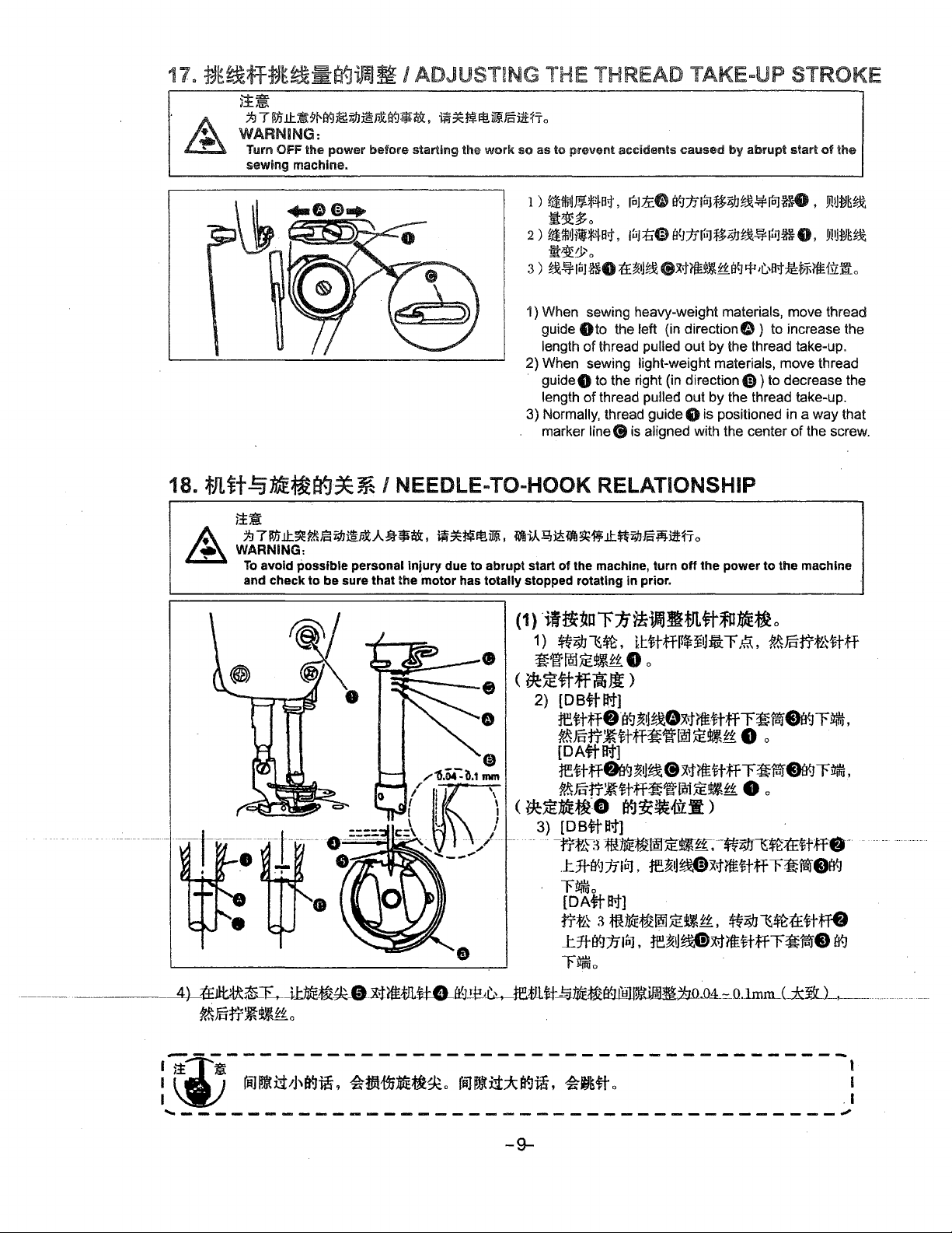
1)
iiiittJJ!J~a1,
ro1ti:O
Ef.JnlPJf:t;tJ~~icJd,
of
v11J~t~
~1t$o
2)
f;UJ,J1'~a-t,
1uJ1:16>
H'~JJfulli~~~1tJ1~8.
Y11JfJE~
fi~:P 0
3 )
~%
loJ
~-
t£~1J~
8~7fUI
1) When sewing heavy-weight materials, move thread
Oto the left (in direction O ) to increase the
guide
of
length
2) When sewing light-weight materials, move thread
guide8
length
3) Normally, thread guide 8 is positioned in a
marker line
thread pulled out by the thread take-up.
to the right (in direction
of
thread pulled out by the thread take-up.
8 is aligned with the center
£~
a<J
i:r
,(:.,a,j
Ci))
to decrease the
:M:tii'1£1irfL
way
of
the screw.
I NEEDLE-TO-HOOK RELATIONSHIP
~~~ij!j}j,
the motor has totally stopped rotating in prior.
~i,kQ,Jii~~ff;ll:.~f;fj.g~ii!fio
the
that
--~4)-~Jlt!lt~~-il:1iti~-~-0-:xitt111.-t±e-fr~lk&,-retJUt_!J_11fe~EfilM~~j;_Q~o_4_~_n.1mm___(_±it_L_,_______
M.15tr~~£f'.
o
-9-
__
_
Page 14

(1)
Adjust
1) Turn the handwheei to bright the needle bar down to the lowest point
(Adjusting
2)
(For a IDB
(For a DA
{Adjusting
3)
(For a DB
ascending needle bar with the bottom end
(For
ascending needle bar with the bottom end
4) After making the adjustments mentioned in the above steps, align hook blade point e with the center
needleG. Provide a clearance
then securely tighten setscrews in the hook.
[
~-
i
the
timing
the
needle
needBe) Align marker
thentighten setscrew
needle)
then tighten setscrew
position
nieedie) Loosen the three hook setscrews, tum the handwheel and align marker line
a
DA
needle)
- -
!f~h-;
specified
sidppfing
Align marker linee>on needle
Loosen the three hook setscrews, tum the handwheel and align marker line G on
cle-;,;;
value,
wm
betweero
bar
height)
8.
9.
of
the
hook
be;.;e;
the
result.
the
needle
!ineOon
f))
of
0.04 mm to 0.1mm (reference value) between the needle and the hook,
llie-
blade
point
and
the
hook
as
needle
bar&
with the bottom end
bar&
with the bottom end
of
needle bar lower bushing
of
needle bar lower bushing $ .
bfia;
of
hook
;;nt;
wm
ho;k
be
damaged.
follows:
of
its stroke, and loosen setscrew
of
needle bar lower
of
needle bar lower
f)
.
~;.
~,;;
If
the
;;e;d;;
clearance
i;
;,;.;
is
larger,
'----------------------------------------
19.
~=Ai~~~~
I HEIGHT OF THE FEED DOG
8.
bushingf)
bushing&
€)
on
of
fua-;;
ihe-1
stitch
,
,
I
I
.,,,,....,
eaz=r.
....
- - -
If
i
\
____
20a
~
the
~~3fa{]ftffi:~ I TILT OF
~~
WARNING:
....
--=:.
-
the
motion
calmping
~
pressure
of
b,!C2_~S_.!1~'2'·-
::J.J
7 flJ.LI.tiO~l'f.l~ilh@Pli'fl*tt,
Tum
OFF
the
sewing
power
machine.
0.8-0.9
- - ue:111'
the
forked
________
before
mm
aa.D
- - - -
tis
insufficient,
portion
THE
~~~1$JJtsiUT
starting
imi7
Q) tr~~-tT~;ffr.~3;!_ 9 Et~~ffi'l~~~-
®
@
,-------------------,
1
~
~
-------------------✓
To
~
adjust the height
CD
i
® Move the feed bar up
!
® Securely tighten screwf).
I
FEED DOG
o
the
work
so
as
.iliifti
.sFa<J?J!i~at
J:
r~~*~f1ittfi~i1
tr~reti~~tt8
ii
it
miffiJJ
1t~~mT
Loosen
to
prevent
screw@
accidents
,,
o
0
i:UO~ffi",
o I
of
the feed dog:
of
~
.,f
3'l
~
~;JJ fi:
crank
t)
.
or
down to make adjustment.
ca1U1sed
by
abrupt
start
of
Ji!tl
the
~
I
0
~)ft
0
G
wJJ.:.
wrF
/ Front
/ Front
up
down
E) tt:fii / Throat plate
/ Standard
-10-
Page 15

~-----------------------------------------,
I
it
II
I
I J
~
- llillllllll!l3 -
1) 'The standard tilt (horizontal)
2)
3)
~~7*$~ZFA,m~ffi~~~~~~~,~~~~~o
-.:I
- - - - - - -
aligned with marker dot
shart by
To
feed bar shaft
To
shaft 90°
90°,
as standard).
tilt the feed dog with its front up in order to prevent puckering, loosen the setscrew, and tum the
90°
tilt the feed dog with its front down in order
in
the opposite direction from the arrow. (The standard tilt for.)
...
- -
~
- - - - - - - - - - - - - - - - - - - -
of
the feed
CD
on feed rocker O . (the marker dot@) inclines forward the feed rocker
in
the direction of the arrow, using a screwdriver.
dog
is obtained when marker
to
prevent uneven material feed,
....
-
dot
G on the feed bar shaft is
tum
~
the feed
- -
I
I
~
bar
~-----------------------------------------,
I
I
Whenever
necessary
the
to
feed
check
dog
the
tilt
is
height
adjusted,
after
tilt
the
feed
dog height
adjustment. I
will
be
changed. So,
it
is
I
'--~~-------~--------~--------------------~
/ ADJUSTING THE FEED TIMING
~-
~7~~~~~~~~A~•tt.~~~~~,ffl~~~~~~tt~~~~~fio
WARNING:
To
and
--~--
avoid
check
possible
to
be
personal
sure
Injury
that
the
Standard feed timing
~
.is4fifflul~mf
Advance_d
0
( j,;:{j;fflf,L!fl;)g
~=
Delayed
=+=
due
motor
:fitff
feed
feed
to
abrupt
has
totally
timing
timing
-
start
of
the
machine,
stopped
1)
2)
rotating In prior.
rN1~*~~,t.,8~0EBffiHE~tt
~~~&-~~~-~*$-~8~,~~~
ffij~~fio
~$~~&~¾*$~~tt~T~~.*m~L
00 ~ tHL.r.t41tx-t
3)
•~*$fflm~~~$MM~,M~&~~~-
~*tliffi,t.,
4)
~7~»a{J•~~-~fflm~.•~•~~~•
;tJ{fU"',8~a
turn
$ ttif1i_t iii
8/(e
0
off
the
power
a{J
1ft:i:
to
8,
the
o
machine
8,
~•~
··
···
·•-----
------· ·--1TToose·n
the
For
2)
eyelet
3)
To
cam
4)
To
opposite,
:,...
~
I
~
.....
- -- - - - - -- - - -- -
screws·•
arrow
or
the
standard
are
flush
advance
in
the
direction
delay
the
direction
Be careful not to move the feed eccentric cam too far, or else needle breakage may result. · :
and
opposite
adjustment,
with
the
the
feed
feed
timing
from
o-ifffeea
direction
top
surface
timing
of
the
arrow.
in
order
the
arrow.
·ecc·enfric
of
the
arrow, and
adjust
so
of
throat
in
order
to
increase
-.
- -
·c-~im
e-
,-move··mefeecJ
firmly
tighten
that
the
top
surface
plate
when
the
to
prevent
....
-- - - - - - - - - - -
stitch
uneven
tightness,
of
feed
material
the
feed
dog
move
·eccentnc·c~fm
screws.
dog
and
descends
feed,
move
the
feed
--
the
top
below
the
eccentric
...., - -
·
in
the
-11-
tne··mrecfion
end
of
throat
feed
cam
~
-
--
or· ---
needle
plate.
eccentric
in
the
- - --
J
Page 16

22.
~*.&1¥Jila.l~
~~
7;J
; WARNING:
Turn OFF the power before starting the work
sewing machine.
7
I ADJUSTMENT OF THE
ltti
.it~
1Nt-.1
~~X§'.PJt 29~$: ,
~~~It!
· I
PEDAL
~J5i!fi
o
so
as to prevent accidents caused by abrupt start of the
(
1)
,t*~~~~
I )
fulf.r~::irrtJ1tisiJ~ffi:ijijT,iffi:
.itmtt.
(
2)
•t]itt-Jjn)jf
1 )
iJ~11itmHs~*lfHJtufgl_
~o
2)
trfliJ~il~li~G, iilili!mA~mH 8111:fi-~~o
(1}Installing the connecting rod
1) Move pedal 8 to the right
the arrow so thtat motor control lever
connecting rod 8 are straightened.
(2)Adjusting the pedal angle
1) The pedal tilt can be freely adjusted by changing
the length
2) Loosen adjust screw 8 , and adjust the length
------
-eewifleefn"l§-md-8-~-
¥.-1t~o
of
the connecting rod.
8,
iJ:~~tt;f:f -
Fl
r:a:ttf!&i3£Mtt&B'-Jftw~JJ.
or
left as illustrated by
~
8 and
of
(1) The pedal is operated
1)
The
2)
3)
The
The
machine
machine
machine
runs
at
low
runs
at
high
stops {with its
in
the following four steps:
sewing
sewing
speed
speed
needle
up
when
when
or
down)
you lightly
you
( 1 )
lfil}i~41'rm-&j£fifflf1:
1 )
1°J
wJ~~~iif :f&A1~.ilffitl6) o
2 )
WfflnrtJwr~~:f&YW~~ifli~f;tt1JGo
3)
re~~fulftlJJt.lJ~~:itl!:li!{itl~l&_tfl'-JfiziUl
further
when
mm~1r.eo
depress
depress
you
reset
the
the
the
c
front
front
pedal
0
mt+
tWlt~r~ll:ffiit)
part
of
the
part
of
the
to
its original position.
pedal.
pedal. G
CD
(9
-12-
Page 17

24.
~!ktl=f~fflJtif
I
ONE-TOUCH TYPE REVERSE FEED STITCHING MECHANISM
(1)
How
to operate
1) The moment switch lever 8 is pressed, the
machine performs reverse feed stitching.
2) The machine performs reverse feed stitchng as
long as the switch lever is held pressed.
3)
The machine resumes normal feed stitching the
moment the switch lever is released.
WARNING:
.___
____________
==-----]
_____,
Turn OFF
work
by
abrupt start
(2)
Height
1) Adjust the height
easily operated.
(
l)
1!ffl
1 )
tJHf
2 ) rtrfttiffstJatfaJ,
3 ) 1nGfttff,
of
jJ
~
*f£iff
the switch lever
8 ,
911Jif.~Pis@IitliEflo
the
power
so
as
to
prevent
of
the
of
switch
lever8
fJ'!i3JVL.:fr.l:tP~:h71i
PJI».:iHJriftJf.iio
before
starting the
accidents
sewing machine.
so that it can be
1
1*
caused
,
Jt!:fiimil
o
25.
Eg-r~~
Jt~
1-1
T
WARNING:
Turn OFF the
sewing machine.
I
ELECTRONIC
!S'h
J.l:.~~Hfl~i;f:l~PXl¥.f~~,
power
before
CLIP
starting the
WIRE
iN~Jf~imtJ§ni:fi o
/2\
ill
(
2)
1 ) iltEfF:¥:t.Uf8a{J~JJt~~J1J~fflJJ~agfftila
work
so
1)
2)
..
II
,&
i£
,93:f,.
jf3cf£::f.f~~Jt
as
to
prevent
Electronic
Electronic
accidents
1;J
7
WJ
lr..
*
~~
if*~~iffifflltfrr
caused
clip
clip
wire
wire
by
8
& open
;Jj
niJi\t
o
abrupt
~
start
as
*Mr
9
of
the
lmm,.,
·-1
-13-
Page 18

26.
-~ffi~,
~~
J:J
7 ~ .tl:.~5'Hl9~i;iJ~~B9¥?&,
WARNING:
Turn OFF the power
sewing machine.
~~}®!~
DISASSEMBLING
~*tf
lt~Fcillff
before
starting the work
so
OF
OPERATION
~'
as
to
prevent accidlents caused
PANEL
by
abrupt start of the
Disassembling
<Qf!-
{00~@@®@0~:
I
®@0000&11~
1.Use needle
to
--
open
steps
a.b.c.
:1
~';
~
-
•
: ®
@@(±)
®eeee
2.
*-2*-2~3f~~ffil&A.
---
------------
$J[a{tr.~.
2.·
operation
see
the
3.Twist
screw
down
panel a.
the
B.
b.
screw
r::::nn
C.
,ffl~,
c.
•..
"
Jlf:fjil
place
To
4.Remove
~zvil
Install
the
assembling
first
the
the
of
operation
steps
operation
disassembly
•
panel, Set
panel according
after
aside
assembly.
-14-
to
Page 19

0
PARTS
SECTION
- 15 -
Page 20

1
JJl~
MACHINE FRAME&MISCELLANEOUS COVER COMPONENTS
*
9~~
14::
71
j 72
12
50
29
28
2
~-◊--~~
I • I
I ' 1
:s2
~I
I 53-
I
54
L-------
~
--J:
"1
I
I
I
I
73
-16-
Page 21

1 .
FF%
Ref. NO.
l 102.01-01-P
2
3 02-608440421-1
4 102.01-04
5
6
7 102.01-07
8 02-412280923-1
9 102.01-09
10
11
12
13
14
15
16
17
18
19
20
21
22
23
24
25
26
27
28 102.01-28
29
30 102.01-30
31
32 101.01-32
33 101.01-11
34
35
36
37 101.0
38
39 101.01-39
40
41
42
43
44
45
46
102.01-02-P
102.01-05
102.01-06
102.01-10
102.01-11
102.01-12
!02.01-13
02-412281423-l
102.01-15-P
102.01-16
02-512281821-l
102.01-18
102.01-19
102.01-20
101.01-21
101.01-22
101.01-23
101.01-24
101.01-25
101.01-26
02-412280623-1
02-412280623-1
02-611400621-1
101.01-34
101.01-5
101.01-36 :#(:~t/i
101.01-38
101.01-40
02-90940042 l-l
02-815280711-l
101.01-43
101.01-44
02-211400621-1
02-211400623-1
{ct
Part
l-37
Cl
'J
NO.
~
~
ffi~
ffiitlim
~rdJ~~~
oo
:tli~JJ
rm
ti$#
~E~lilf
ffi~fL~
ttnaam~:rL~
~mtttr~~
JfiiH&tin
%~~;j:Ji
Fofilif&
J§-fiJ
tHL~
ffii
~
~tffi
Jt
Face plate
Face plate agsket
Screw 1/8x44 L=4
Arm oil shifld asm.
Rubber
Rubber plug
Three eye line board
Screw 3/16x28 L=9
Cord holder
Side plate
Gasket
Face plate
Description
plug
~~i~jf-:M! Safety label
Po
m
ifJi~
fT
m1c
J!;JBl.
~11
IHL
~
,,1ti~
~~~~tr
fftlttliHJL~ Reverse feed lever stopper
r~lHUl
~~~~~
OO~~~~tll#
oo~~~~ir
~~M~JUJi
/j\~~{!i
/j\~~-
/j\~~~iij:
/J\~~~til-ttt~n
tittJUfWitfl.a
tJt~fflP
~tin
tr~~
~~~~tr
~~~fli1Lt
~~ti-m:
~~iff!J~-ti
~~-
~~~
#(:~~tr
i:Jt~Jl
13lt~jfWJ-=p
~
~~~n~iMt~n
~~$iJtr
tl~$J
H~
n~~n
it~t,n
Screw 3/16x28
Machine cover
Rubber
Screw 3/16x28
Rubber plug
Magnet cord rubber
Thread
Thread tension
Thread tension guide
Thread tension disk
Thread tension spring
Thread tension
Screw 3/16x28 L=6
Thread take-up lever cover
Screw 3/16x28
Arm
Screw 1
Thread
Tension
Rotating stopper
Tension spxjng
Thread tension disk presser
Thread tension disk
Tension post
Take-up spring
Tension post socket
Screw 9/64x40 L=5.5
Screw 15/64x28 L=7
Tension releasing
Throat plate
Screw l
plug
tension asm.
thread guide Right
tension asm.
Screw l
l/64x40
nut
l/64x40
l/64x40
L=l4
L=l8
post
nut
L=6
L=6
L=6
L=6
~
Qty
It
~
It
Note
1
l
1
1
3
1
1
7
1
l
l
l
l
3
l
l
l
l
1
l
1
l
1
2
1
1
1
l
I
1
l
1
1
1
1
1
2
1
l
1
l
l
1
l
1
1
-17-
Page 22

1.tll~
~
9~~ffB14:
MACHINE FRAME&MISCELLANEOUS COVER COMPONENTS
~
61-'f 1
60-~
12
50
a I
29
28
2
I
-
r------.
lo")
I
l '
1s2
I 53-
I
L
_______
~I
~
~ I
54
..
8 9 10
I
I
!
I
I
~
11
30
57
43
,
'
31
~
.;
'
/
4140'
I 38
39
'-
',
',
37
,._,_
36 ,
35
","',
34
~
~
.,A(
'---......,_
~
'--1--·J
32
~
33)
7i
17
18
19
~
1
',
',
~
5261
''
.,_
___
I
I
_J
73
I
I
-18-
Page 23

1 .
ff~
Ref. NO.
47 101.01-47
48
49 101.01-49
50 02-412280923- l
51
52 101.01-52
53
54
55
56
57
58
59
60
61
62
63
64
65
66
67
68
69
70
71
72
02-61140062 l-1
101.01-51
101.01-53
02-606560221-3
102.01-55
101.01-61
02-911400611-1
101.01-63
102.01-64-P
102.09-32
102.09-33
102.09-34
102.09-35
102.09-36
102.09-36-01
102.09-36-02
102.09-36-03
102.09-36-04
102.09-36-05
102.09-36-06
102.11-34
102.11-35
14=
Part
~
NO.
~
~
ii:.~¥-J
ii:.~~~tr
ffiftli~Ti-:JL~
oot&~n
mtlitflWt
;JttJi
tttliiif
tt~Jfffltr
~~Jttt
~3tlff
~mff.~n
~%AA!
~%AA!
t3t~ff.t.H.
t)t~ff.~tr
1
~~ntin
i~~~~tUa#
t]t~
f)t~~~~tr
~~~~JBfti~
g}t~~~~
~~;ii~~
~~~~!l~-ffJ: (
lt!tll.~%
ij!
1
1~n
~~!l;l
mJJ.~
iYP
tr
,flf Bobbin base
-BJ:
lffi
• tr
Ann
thread guide Left
Screw
ll/64x40
Ribber plug
Screw 3/ l 6x28 L=9
Slide plate asm.
Slide plate
Bed slide spring
Screw 3/32x56 L=2.2
Bed
screw stud
Ruler stopper
Screw 11/64x40 L=6
Pole
Model plate
Screw
Knife
Knife screw
Thread
tension asm.
Tension nut
Tension post
Tension spring
~)
Thread
T~ead
Tension nut
Motor
tension disk presser
tension guide
cover
screw
Description
L=6
J
~
It
~
a:
Qty
l
l
Note
2
3
1
l
l
2
4
l
2
2
1
1
3
l
2
1
1
1
1
2
l
1
l
3
- - -----····--
-----
- +
-
--
--
---
--
- ---
--
---
-----
--·
---
----- - ---------
--
----- -
----
-----.
----·-----------~-------
----
-
-19-
----
-
---
Page 24

2 .
.l:$dl
MAIN SHAFT&THREAD-UP LEVER COMPONENTS
· ~t~$14:
jJ'--29
30
4 1·
42
2~.
1~
'1:4
6
~5
6
46--c4)
_/"',..._I
40
45
~
34
-20-
Page 25

PF%
Ref.
NO.
1
02-815281151-l
2
101.02-02
3 101.02-03
4
101.02-04
5 101.02-05
6 101.02-06
101.02-07
7
8
101.02-08
9 101.02-09
10
12
13
14
15
16
17
18
19
20
21
22
23
24
25 101.02-25
26
27 102.02-27
28
29
30 101.02-30
31
32 102.02-34
33
34
35 101.02-41
36
37 102.02-43
38
39
40
41
42
43 102.02-49
44
45
46
102.02-10
11
02-818281651-1
02-816400611-1
101.02-13
02-418281651-1
102.02-15
101.02-16
02-516401111-l
101.02-18 *flifii,c,~
02-409400623-1
102.02-20
102.02-21
101.02-22
102.02-23
02-816400611-l
101.02-26
101.02-28
101.02-29
02-815281051-1
102.02-38
101.02-40
101.02-42
102.02-44
102.02-45
102.02-46
102.02-47
102.02-48
102.11-36
102.11-37
102.11-38
Part
%
NO.
15
tlt~5tff~~tr
i:JE~5tffffi
lfl3
WHm
it~
~t~~ff
tt~~ff
tlt~iff~it~~
7tffl
~
Screw 15/64x28
Thread take-up crank shaft
iWJ
g Roller felt
Jhread
14
Thread take-up
Needle bearing
take-up lever
tt~llbm$14 Needle bar
ttffl!ff
~t~
db m tcME~
n
ttffdbmm#
ttff
lin
m~
1~u1n
tt~dbm'AI m•n
~
1il•tro~l!J
ttff
dlrWtiE
un•
tr
ttffdbm
*~~,c,~m-w:
*fH~,c,~•tr
*flifii,c,~m:¾&~tr
!ftbjf(
J:
!fib
nb
jg'
tit
;f
~tHf
J:
$W~
_t
!fib~
J:
!fdlmJ!ftb~
db
ft1i
rfh
_t
!fib
tp $di~
~~~
1=1m
Ill m 14
Ill ~n
A~iHij
Ill Snap ring
~El~
tJt~~ffffl~tg
:f-~ffltr
¥~
..t!ftb
J:~nb:!tiftilil~
_t
!fib
nh
:ltiffiJ
Ti
mo~
*fl~,t.,flil1&lii
J:~
JP
!fth~•n
~$fbff
(A)
~!fdl$~Mt!J
~$ib1Ultr
~jJ\m
~!ftbff
~!Mff (
lt~~~:tJUll#
~m~~~n
~m~~~n=tsJt
(
B)
B)
ffil~~fJ
Needle bar
Left screw 9/64x40 L=4.8
Counter weight asm.
Screw 9/32x28
Screw 1/4x40
Rubber ring
Screw 9/32x28
Counter weight
Feed drive eccentric
Screw 1/4x40
Feed drive eccentric
Screw 9/64x40
Needle bearing
Oil seal
Thrust collar asm.
Screw
l/4x40
Main shaft front bushing asm.
Oil adjusting collar
Bushing,intermediate
Cable band
Rubber
Thread take-up
Screw 15/64x28
Hand wheel
Main shaft
Oil amount adjusting
IIJ
Rubber ring
Thrust collar
Screw
Connect
Connect
Screw
Needle bearing plate
Connect block B
Screw
Motorasm.
Screw
Washer
block
rubber
Description
L=l0.5
le_ver
asm.
crank
crank
rod
L=l6
L=6
L=l5.5
cam
L=l
l
cam
L=6
L=6
crank
L=l0
A
A
~
asm.
shaft felt
pin
Wt:
Qty
;,
~a:
Note
1
l
l
I
l
2
l
l
l
l
1
2
1
l
1
I
2
1
2
l
l
1
1
2
I
1
1
1
1
1
1
1
l
1
1
1
1
1
1
3
l
1
3
1
4
4
-21-
Page 26

3.ttff- · ~;HI •
7';&1~14:
NEEDLE
1-g
BAR,
UPRIGHT SHAFT&HOOK DRIVING SHAFT COMPONENTS
r--------------7
:
r-
r-----7
I I I
11
11
I I
I I
I I
I I I G
I I L
I I
I I I I
I : I
• t J I ,
I
, I I
I L
L
ti-,-1s
1
l
~
~
I
~,
I " I I I
I I I I
_____
r--~o-
~17
I.
_____
__________
r----------7
, r
I I
11
19
11
+·-
-1-----
I I L
20
l~I
I I I I
-i-
~-
____
,----7
l~l-1
I~
I I I I
I I I
LL
~
w----221
L
_____
--7 :
I I I
1
I I I
14
'-
~
I
_J
7
l---15
I I
_j
~7
r'
I I I
+
_J
~21
::J
--
11
I I
l-13
I I
I I
I I
_J
, I
I l
--+·--··---j---
118
: :
I I
I I
I I
_J
__
_:
I
I
I·
l-
12
-·
I
I
(
I
I
36
I.,,.,.-
/
38
37
- 7
\
\
I l )
1
L
____
®-30
_j
I
-22-
Page 27

3.
ff%
Ref. NO.
I 102.03-01
2
102.03-02
3 102.03-03
4
102.03-04
5
02-50940082
6
102.03-06
7
!02.03-07
8
102.03-08
9
02-50844052 l-1
10
11
12
13
14
15
16
17
18
19
20
21
22
23
24
25
26
27
28
29
30
31
32
33
34
35
36
37
38
39
40
41
42
43
102.03-10
101.03-11
101.03-12
101.03-13
101.03-14
02-816400811-1
101.03,-16
02-816400811-1
101.03-18
101.03-19
02-816400811-1
101.03-21
02-8164008 l l-1
102.03-23
101.03-24
102.03-25
102.03-26
102.03-27
02-812280711-1
102.03-29
02-511400511- l
102.03--31
101.03-32
02-511401021-1
02-81228071
102.03-35
101.03-38
101.03-39
101.03-40
101.03-41
101.03-42
101.03-43
02-612281311-1
101.03-46
#
Part
%
NO.
l-l
l-l
:g
Htt
_tfL~
Hff_t~
Hff
Hff~~tHR#
tHf
itttti:tJtJ
Hffitmttttm
HffT~~~
Htfr~
mttt,n
Hfft\t~
mn
{it:
m-
$£
~il
ftj:
__t
t&~!il
_t
$HI~
is
14
ft:
f_g
1tt:
{il:w~~n
!!£
~__t1¢t!Httli
*t!t~~n
Tili~t!l#
Yz~Tffi~ift#
~W~tin
r~~w~~Ji#
~m~~n
~~
~~
~$WJ:.~~
~~Ttml~
r$mE$W~
~
$1
__t
~~ml
T$mt~l!ltii#
T~t~~~n
T~
1iJE~~1ft~
:111e~~fft~ffltr
rtfinru~~~tr
T
~anru!fm
T~IS&nb~Ji11
T ~ !~I.Um
T~~im~tr
~Jc
...
~~
:titi~~1€~ii#
T!tilljj§-!fm~tin
tttf
~~ttffl-:!k~
~tr
~
;rt
~
1tJ:
Description
Cap
Needle
Needle
Needle
Screw
Slide
Needle
Needle
Screw
Needle
Needle DBX1 #14
Gear&pinion
Gear&pinion
Gear
Screw 1 /4x40
Pinion asm.
Screw
Gear&pinion
Gearasm.
Screw
Pinion asm.
Screw
Upright
Hook asm.
Upright
Upright
Bushing
Screw
Thrust
Screw 1 l/64x40
Lower
Bobbin
Screw l l/64x40
Screw
Lower
Oil seal
Oil
Oil
Bobbin
Bobbin
Hook
Screw
Slide
bar
bushing
bar
rod
holder
9/64x40
block
bar
thread guide
bar
bushing,lower
1/8x44
L=4.8
bar
thread guide
asm.
asm.,upper
asm.
L=8
1/4x40 L=8
asm.,lower
l/4x40
L=8
l/4x40
L=8
shaft
shaft
bushing,~pper
shaft
bushing,lower
rear
3/16x28
collar
asm.
shaft
case
holder
3/16x28
shaft front metal
screw
asm.
wick
seal
screw
cas_e
bobbin
block
case
3/16x28
base
L=7
L=7
L=7
L=l3
upper
asm.
.5
L=S
L=9.5
asm.
~
Qty
1
1
1
1
3
1
I
1
1
1
1
I
1
1
2
1
2
1
1
2
1
2
l
1
l
l
I
1
1
2
1
I
1
1
1
1
l
1
l
1
1
1
1
it
~
Note
ti:
-23-
Page 28

4.ffi;ff
HAND LIFTER
'$1!:f
2
COMPONENTS
~-17
·~
I
-24-
Page 29

ff%
Ref.
NO.
1
2
3
4
5 102.04-05
6
7 102.04-07
8
9 101.04-09
10 102.04-10
11
12
13 102.04-13
14
15
16
17 02-515281521-1
18
19
20
21
22
23
25
26
27
28
29
30
31
32
33
34
35
36
37
38
39
40
41
42
43
44
1tt:
Part
101.04-01
02-50940 l 023-1
101.04-03
102.04-04
02-409400821-
101.04-08
102.04-11
102.04-12
102.04-14
02-411400521-l
02-411400521-1
102.04-18
02-412280623-
102.04-20
04-612320400-
101.04-22
101.04-23
102.04-25
102.04-26
02-412280623-
102.04-28
102.04-29
102.04-30
102.04-31
102.04-32
102.04-33
101.04-35
102.04-~6
02-816400811-l
02-50940082 ! -1
102.04-39
102.04-40
102.04-41
102.04-42
102.04-43
102.04-44
102.04-45
_a
7
NO.
1s
~
&~~¥
BiJJl;llt&¥~n Screw
&~
~
-=j=.
~Ofill It]
ffifJilltm-¥8~${4
fftf~~
l
mff~~tr
riitIJf
~rt
ffl
~~~3ft=lt4i~
ni1EJ'41$,f4=
Tff~~,lli
tft
ffiJJ!IJ:m
ff~
n
Jsttff$Jilltitr
rttlliJJil!JJUf
~ttJJil!Fotiff
Tff~~~~tr
_tffiAJi~
~
t~n
Ttttlitll#~~~n
m~ml:k~
l
_tf[
~gJi
,ftf=
~~-tr
_t,8£~~ti
l
:m~fflieOOTi'~-BJ:
~tt
ffl3f
a~
Fi
¥.HJUvU&~
!fkiftr~~
fl~~tl°
l
~1S;fliiH~
fl~JJi~
f'l~JJUJi~~ffi
~
ffi~
ifµ]
lli
•tr
~J.li~
E[tf~Yi@
EEff
~~~--Viti]
Biff~~~n
~~~-=µ~~tr
oottff
tf:i
tt~~;f:Iff
~ffffct~III
lliHkPfHffli
:ff-~i~~m:ffu~;J
te-
ffi1}1q1jiz
~ffi~ff
1ftjf
~fr
-BJ:
m #
tlHtt:
ff
Description
Hand lifter
9/64x40
Rubber ring
Hand lifter
Presser
Screw
Link
E-ring 5
Presser foot asm.
Wire
Hinge
· Hinge
Knee
Lifting
Screw 1
Screw l l/64x40
Screw
Wire
Screw
Wire
Nut
E-ring
Tension release
Wire
Tension release supporting
Screw
Thread
Tension
Presser
Presser
Presser
Presser
Presser
Presser
Screw
Screw
Knee
Hand
E-ring
Lifting
E-ring 5
Knee
Presser
bar
9/64x40
shaft
holder
screw
screw
lifter
lever
15/64x28
holder
3/16x28
holder
3/16x32
5
cable
3/ l 6x28
tension release wire
adjusting
spring
adjusting spring
bar
bar
bar
l/4x40
9/64x40
lifti~g
lifter link
5
lever
lifting
guide
L=lO
cam
bushing
L=8
bracket,lower
connecting
link
l/64x40
L=6
bracket,upper
return
holder
L=6
release
shaft
regulator
guide
thread guide
L=8
L=8
cross
cross
bar
asm.
lower
L=5
L=S
L=l4.5
screw
.brocket
rod
rod
rod
spring
nut
asm
pin
,'.~ty
1
I
1
1
1
l
2
3
l
1
1
l
1
1
1
1
l
2
l
l
2
2
1
I
1
1
1
1
I
l
I
. I
l
1
1
2
l
1
1
l
l
l
l
~
Note
ff
-25-
Page 30

5.~~$14=
FEED
MECHANISM COMPONENTS
1
~b~89
18
2
~
17
16
6
10
11
12
~
13
15
£?
~
27 •
28=.j
29
30 32
~
I
I .
',
l'~_j
53
I
t
55--j
I
l s6 I
L-----~
I
I
33
31
I
'1--51
"-.
35
36
59
_:J
Lsa
I
r
I
I
l._
---...
45 '
44
41
-26-
Page 31

FF%
Ref.
NO.
1
2
3
4
5
6
7
8
9
lO
11
12
13
14
15
16
17
18
19
20
21
22
23
24
25
26
27
28
29
30
31
32
33
34
35
36
37
38
39
40
41
42
43
02-412281621-1
44
45
46
¥F
Part
NO.
102.05-01
102.05-02
02-50940062 l-l
101.05-04
101.05-05
02-31228072
102.05-07
102.05-08
102.05-09
102.05-10
02-512281821-1·
102.05-12
102.05-13
02-809400424-
102.05-15
102.05-16
102.05-17
101.05-18
102.05-19
102.05-20
101.05Q2]
102.05~22
102.05-23
102.05-24
102.05-25
l02.05-26
102.05-27
02-815280711-l
02-809400424-1
102.05-30
102.05-31
101.05-32
02-608440621-1
102.05-34
101.05-35
02-411400523-1
102.05-37
102.05-38
102.05-39
02-509400621-l
04-618280400-1
101.05-42
102.05-44
02-412281421-1
102.05-46
l-1
%
15
~
1iu~~aff
1ftl
~?}Bl
i~H~
~tH~~B
*~iffiJ~S
~~~=µ'~$~
*~ifti3i'5"$~~~n
*~
i)~
TJ
~ti
~~
Re
tm
fr1ii
J!~1€
js~
~~
tJJf
1H~
HeiifEm
ie111Em ~ n
~fHtitf
*~:iifff§
l
*~jiff~n
t€i~~;ff
*
;f6i.
ifµj-=p
~~
:t&~:tl
ff~*~
fftl~~
~fiOID!
:i&ff
ab
WWHtf:
urJI
WH~
lffl
[II
1ftlm~eam~$)"
1ftl~~:itffft~
~
1ftl~~H:ft~
~"1i91if&~~~ Walking
~~*
~~m:mig]
*~ffl!
m
;tJ
:f!i
lf1i
igJ
t&~iil #
*fl~i91ifli~ti.ti~
le ;;ii ffl
~
tr
~ffffi~fT
;f~ffi
*~~
$IBJlH'~
Im
~~5f
*fl5f~tr
5f~W#
m~t1i~~
~
1irt&~~~tr
mti
tHt~JE;ti
~~·fih
*#liil:ftJiffl
(MrfW~~n
t~
5f J!ff~1il•-Ht
~~
lttl
tvmHtt:
~~aam•ir
rg.
w
;gab
tw
t1l
1lt
tfr5f
Fooom•n
1ft 9.fitfftfBI1iz~tr
Description
Feed adjust rod
Feed regulator pin
Screw 9/64x40 L=6
Feed regulator
Feed regulator bushing
Screw 3/16x28 L=7
Feed regulator screw
Spring
Feed
adjust
pin
Feed
dial
Screw
3/16x28 L=18
Rocker shaft connecting rod
Walking foot long pin
Screw
9/64x40
Connecting
Rubber
Feed
E-ring 5
Feed
Screw
E-ring 5
Spring
Connecting
Connecting
Feed
Adjusting
Screw
Screw
Feed
Retaining
Fedd
Screw
Feed
Adjusting
Screw l l/64x40
Feed
Feed
Walking
Screw 9/64x40
Nut
Feed
Screw
Lifting
Screw
Hinge
ring
reverse spring
reverse
adjust
l 5/64x28
9/64x40
bar
dog
l/8x44
bar
spring
rocker
9/32x28
rocker
3/16x28
rocker
3/16x28
screw
rod
arm
foot
short
link long
link short
link
link
shaft
ring
I
asm.
link
hood
shaft
foot
middle
shaft
L=4
asm.
pin
asm.
fulcrum
L=7
L=4
L=6
spring
L=5
L-6
crank
L=l5.5
asrn.
L=l4
pin
pin
shaft
guide
pin
asm.
~
Qty
2
2
2
2
2
2
2
2
~
1±
Note
1
l
2
1
l
1
I
l
1
1
l
1
1
1
1
1
1
1
1
1
1
I
I
1
1
1
1
1
1
1
1
1
I
l
l
1
l
1
-27-
Page 32

5.~~iB14
FEED MECHANISM COMPONENTS
18
~
12
2r
24 -2sj)
o-~
Ill
I
31
2E,
l__
19
I
_,,,,.-
G
- JJ-20 1
/.
22
'
I
17
11
~
~
---~t4
---..._,
r
45 '
I
I
~
44
___
_
41_
I
L4a
49
'7.:-._'...J
I
I
',
53
55---f
l',~4_1
I
I
I
I
56
I
~51
I
L----~
I
59
_:J
L5a
I
-28-
Page 33

}¥%
Ref.
NO.
47
48
49
50
51
52
53
54
55 102.05-52
56
57
58
59
60
61
62
63
64 02-816401041-1
65
1tt=
Part
102.05-47
102.05-48
02-816400611-1
102.05-49
02-411400721-1
102.05-50
102.05-51
02-412281421-l
02-511401121-1
102.05-59
102.05-61
02-816400611-l
102.05-63
102.05-64
102.05-65
02-816400911-1
102.05-68
-'%
NO.
~
t~5f~
tit
5f
~t4i
liWl
#
~
fi-
$la
t4i
!!l
~
n
J!~HrtrwJ$la~
5f$W~tur
tit
5f
$lb~
ffl
t4i
111
5f
~
RJH.fl
1lf
5f~~~n
ta
5f
x
db
m i!l
14
ta5fx!ihmtin
iftl~~i&
!ft3f~t~II
tft
5f
1ftl
*~Hmo~
1ftl*~$ia
1ftl
~)M
1itl*;p1-tJi
1itl*;pj.tJi
itl*~if¥
~
rli
$in
¥~ii
!m
~ n
im
$la~
¥ttir
¥
~
14
fft~n
~
Description
Feed driving shaft
Thrust collar asm.
Screw
l/4x40
L=6
Feed rocker shaft bushing
Screw l l /64x40 L=7
Retaining ring
Feed
bar
crank asm.
Screw 3/16x28
Driving shaft crank asm.
Screw
ll/64x40
Reverse
Thrust
collar
Screw
1 /4x40
Rubber
ring
Feed
reverse
Feed
lever
Screw
l/4x40
Screw
l/4x40
Reverse
feed
metal
feed
L=l4
L=l0.5
control
asm.
L=6
shaft
L=8.5
L=IO
control
lever
lever
asm.
~
Qty
1
l
1
2
2
l
1
l
1
l
1
1
2
I.
I
1
1
I
1
•
-~
~
Note
1£
-29-
Page 34

6.
~
WtJJtUtiftt=
THREAD TRIMMER COMPONENTS
(}-a
32
41
33
I
~
> >
·----
......
,--~
I
L1
1 I
34 35
ao
a1
i~®
Ut
j
37
38
36 I
-30-
I
42~
...,
'~--
39
'-Sf=)-
!-44
~47
li·---46
43
Page 35

6.
fi;°%
Ryf. NO.
1
2
3
4
5
6
7
8
9
10
11
12
13
14
15
16
17
18
19
20
21
22
23
24
25
26
27
28
29
30
31
32
33
34
35
36
37
38
39
40
41
42
43
44
45
46
47
48
49
14
Part
101.13-02 /Jl$.TSM11/64"x40
101.13-10
101.13-07
101.13-08
101.13-03
101.13-04
101.06-06
02-2065603 21-1
101.13-12
101.13-05
101.13-06
02-611401021-1
101.06-13
101.06-14
101.06-15
02-409400523-1
101.06-17
101.06-18
101.06-19
02-916400611-1
101.06-21
02-811400511-1
101.06-23
101,06-24
101.06-25
101.06-26
101.06-7
02-611400621-1
101.06~29
101.06-30
101.06-31
101.06-32
101.06-33
101.06-34
101.06-35
101.06-36
101.06-37
101.06-38
101.06-39
101.06-40
101.06-41
02-409400623-1
101.06-43
101.06-44
101.06-45
101.06-46
02-415280923-1
101.06-48
101.06-49
%
NO.
~
3.f~JgHlfl~II Washer
JJ
~ffi;f;!iffl. #· Partiaiity shank asm.
m~n~JE!ll~-
ffl#JJJ
Yfi-ltj:
SM11/64"x40
~~JJ~
~JJiAl~i11ir
fj~JJ
1!1#Jt
!fl$)'
SM9/64"x40
lflJ;Wj
!MK~
tflt
;Wj
Jt
i;JJ
#<:
~-
!11$.J
SM3/16"x32
-ro~~~
J!1$J
SM11/64"x40
I!IK~dnt1UdJM~
!Jl$J
SM1/4"x40
8~:roitt
8~
M:tML~
!JIU
SM9/64"x40
;i!~;JtJ
:it.ff
-W
~ 8 ~
fflitftti/Hl
SM11/64"x40
db
;fiUm
5¥.
~
tUIK ~ ffl
!JIU
~ti:
!11-lfJ:
~
f=HIJ
rf!lt~~Mt~
-m~i:f!~fkIDiffl
])I'®
~II
nll~~~!ilf!
!fUJM4
-OO~lli'k~~
fl~-~
-Ii
JllfJ
~~
!J1$]'SM15/64"x28
Jve~
'F~fp:J:t~
~
ll!4.5x8x0.5
,flt-
SM1
l/64"x40
SM1/4"x40
SM1/4"x28
itiHlffl
,{jf;tfh
if
~
,lli;fli
·
~
L=l2
L=4
L=l4
L=lO
L=5
L=l3
L=l4.5
L=S.5
Description
Screw
SMl
l/64x40
Screw
Motorial knife
Nut
SM11/64x40
Knife bracket
Screw
Secant knife
Protect needle patch
Screw SM9/64x40
Thread
shear rock arin
Positioning block
·spring
Screw SM3/16x32
Thread
shear
Screw SM1
Short bush
Serew SM1/4x40
Pole
Thread shear
Bale
Screw SM9/64x40 L=S 1
Screw SM11/64x40 L=5.5 2
Krufe shaft connecting
Thread shear rock arm shaft
Spring cover 1
Spring
Thread shear
Screw SM11/64x40
Rool shaft assy
Nut
Thread shear shaft
Retaining ring
Magnetic plug cushion
Magnetic plug
Nut
Washer
Screw
NutM4
Magnetic
Thread loose
Spring
.Screw SM1/4x28
Magnetic plug
Screw SM15/64x28
Electrical plug breacker washer
Bushing,lower shaft
Washer 4.5x8x0.5
l/64x40
band
SM1/4x40
plug
cam
rock
L=lO
cam
rock
arm shaft
pin
cushion
seat
L=13
L=12
L=4
L=14
arm
rod
mat
mat
L=l4.5
~
assy 1
. 1
Qty
2
2
1
2
1
1
1
1
1
l
l
1
1
1
2
1
1
1
2
1
1
1
1
1
1
1
1
1
1
1
1
1
1
1
2
1
1
1
1
1
1
1
1
2
:JI
4-
Note
tt
-31-
Page 36

7.
~
idJ
if'J
ii
~B
1tf
AUTOMATIC REVERSE FEED COMPONENTS
8 0
16
/,,
11
'i°
~~
9 J
~
8.
l:f!-r~~ti,
NEEDLE
i
I
r
I I
----------
I
I
2
-
!
ol
l
□□
I
□□
I J
I I
I I
I
L
_____________________
SELECTION
l-s
.------.
oooo
0000
A~
~ttitffliflf
BOX
--,
18
□□
□□
3-
4-
ELECTRONIC
CONDUCTOR
COMPONENTS
,----------------------
•.
------
I
I
I
I
:
!
1
I
I O O I
!
l
:
:
I I
I
I
,
□--~
□
I
0
oooo
0
oooo
□
□
□
□
□
□□
--------'
□
I
□
0
0
0 t
□
L------------~--------'
B~
HOLDER
I
6-
I
I
j
1
I
l
I
-32-
Page 37

ff%
Ref. NO.
#
Part
%
NO.
~
~
Description
~
Qty
•
* rt
Note
1 101.07-01
2 101.07-02
3 101.07-03
4
5 101.07-05
6
7 101.07-07
8
9·
10
11
12
13 101.07-13
14
15
16
101.07-04
101.07-06
101.07-08
101.07-09
101.07-10
101.07-11
101.07-12
101.07-14
101.07-15
101.07-16
~
;I] 1ftlrt3f~ffi. #
El
;IJ1Itl~miff
El
;JJitl~mifftJn
El
;JJ1ftl~mifftJffl:
itlilflhm
ttl
~
itt1
m•
n
ttl~itt1mtin
itl~fk~
:i!iff
itl~fk~~III
mJt
•1ocmJt
~~IH~·•
itl~~~it~~
ttl~ttm~
~m
~~
ml
tin
itiffJEm•
l{~vel'~e
Automatic
Automatic
Automa~ic
Revers\!
Scam
R1we~e
Reve.-~e
E-1ing
\Vasher
Rubber
J.::-rhig
Plut1gcr
.Kr..•\•ca·~c
sl~tew
Plunger !-piing
feed
revrn~
revef9e
reverse
gtJLcbiag
cnml
::.cn.wr·s
l!titching
feed
20
16x24x'.!.6
plunge1'
4
nrm
fcl·ti
15/Mx28 L=l~
switda
nsru.
stitching
stitching.
stitching
crank
dl)wn
mrnk mews
con.nectiug
pio
magnet
11~m.
rnd&
bars
ban
li.u1
gcrewg
nut
1
2
1
1
1
1
1
1
1
1
1
2
1
1
2
1
Jf%
Ref.
NO.
1
101.08-01
2
101.08-02
101.08-03
3
4
5 101.08-05
6
7
8 101.08-08
101.08-04
101.08-06
101.08-07
#
Part
%
NO.
~
~
)2Qtt~ffi.#
)2Q*~
~~
1mtt
)2Q
tt~
ml
JEtt n
~
r*~*m #
tatt
~r*~*ml)E!lll$J
Description
Needle
~eedle
2-core cabtyre cord
pin
Screw SM9/64X40 L=8
Electronic conductor holder
Conta<:t
Screw
selection
selection
contact
pin
SM3/l
box
asm
box
6X28 L=6
asm
~
Qty
1
1
1
1
3
1
1
1
•
*
Note
13:
-33-
Page 38

9
.iliJ
j~
i:fl31tf:
OIL LUBLICATION COMPONENTS
1 o
.im
11t
:a~
14:
OIL RESERVOIR COMPONENTS
-34-
Page 39

9.
1¥47
'Ref.
NO.
1 102.09-01
2
3
4
5
6
7
8 101.09-08
9 102.09-09
IO 102.09-10
11
12
13
14
15
16
17
18
19
20
21
22
23 101.09-23
24
25
26
27
28 102.09-37
29
ft
Part
102.09-02
102.09-03
02-4122 80623-1
102.09-05
102.09-06
102,09-07
102.09-11
101.09-12
101.09-13
101.09-14
101.09-15
101.09-16
101.09-17
101.09-18
101.09-19
101.09-20
101.09-21
101.09-22
02-6I1401021-1
101.09-26
02-615281221-1
101.09-28
102.09-38
~-
NO.
1lt
~
~
Jf
ffF
Oil sight
Rubber
Main
Screw
Oil felt
Oil return tube asm
Holder
Oil
wick
Oil adjusting screw
Spring
Oil
tube
Lubricating oil
Oil
pump
Oil
pump
Oil pump impeller
Screw D=3 L=I0
Lubricating
Oil
pump
z
tWrM
rm
ffl
o~
WJ
_t~1~1m~
lliI
¥lli
~~~tr
rill
1m
§
~
@1
1ru
~
til
M1m~:%
*f-HliIYIB~
nfi.~11Hltifr.]"'p'~fi"
1itE
~
nil
ii
ntE.~1~1m~
tm
JiHflHlt
tfb*~~if!i
1IB*~
11B
*
ttt
4t
rw*AHJir
1IB*~
rm*
itt
tfMU&
@lrdltt~ Plunger
tt~tt
tt~tt!T
T
~
f~
1IiI
ff
rm*~~tin
tui~m~n
ilh*ii~!Pltt
rw*tin
1~nbif~~
~~~13g~~
f'l~
ffl5g~~m n
Plunger
Plunger screw
Hook driving shaft oil
Screw
Screw l l/64x40 L=9.5
Oil
pump
Screw 15/64x28 L=l2
Rubber
Bobbin pulley
Screw
Description
window
ring
shaft oil tube
3/16x28 L=6
presser
pump
installing base
oil
pump
impeller cover
spring
M3
L=8
support,large
joint
asm
cover
tube
~
It
~
1£
Qty
I
l
I
l
l
1
1
1
1
··-
1
l
l
1
1
1
3
1
I
1
1
l
l
3
1
l
1
1
)
2
Note
1 101.10-01
2
3
5 02-620240721- l
6 101.10-06
7
8
9
10
11
12
13
14
15
16
17
18
19
20
21
22
23
101.l0-02
101.10-03
101.10-07
101.10-08
101.10-09
101.10-10 tit
I 01.10-11
101.10-12
101.10-13
101.10-14
I 01.10-15
lOl.10-16
101.10-17
101.10-18
101.10-19 ~#Aff~
101.I0-20
101.l 0-21
101.10-22
101.10-23
tfb
fK
=tf!Wf:
1m:m:
1mffKm
1~~rm1UtH
14~YJH:fltttro~~
1ft
ffiJJ!IJ
x5t
ro1
ab
m
xJt
ftJ
ab
WHR
Ji
t€iffiM!tl~ff D
J.lil]!p~f,Mff
titJAff--W
~
rcJ
rttrtfi
XR
fol
ab
m
xJt
ro1
6IJ
m
1€tlli1J!IJ~
~tJAfftf!H4=
~f».ff$}(~
~~ff
~fJAf1i
~~ff-Ti~
~~iin
tg.J.liJ]!jIJNt~
t~IIJ
Ti !k
~~
tr
~
fir
iJWfJ
l~tHv:
iJ~
!Pl
tr
Ti~
ti
Oil
Oil reservoir
Oil reservoir gasket
Screw 5/ 16x24
Rubber
Knee lifting
Spring
E-ring
Vertical
Screw
BJ:
NutM6
n
Screw
Screw
Knee press cross
Knee
Knee
Knee
Knee
Knee
Knee
Screw
Knee lifter push
-35-
reservoir
ring
10
shaft fitting
M6
L=30
M6
L=
pan
plate
pan
plate cover
pan
upright
pan
plate
pan
plate
pan
plate
M6
asm
L=7
rotating
17
asm
rubber
support
L=12
.5
shaft
shaft
rod
arm
arm
I
1
1
1
1
1
1
1
I
2
2
2
1
1
l
1
l
1
1
1
l
l
Page 40

11.Mt!~il~14:
THREAD STAND COMPONENTS
12.
II#itf
ACCESSORIES
4 5
10
8
lf}---12
13
14
-36-
Page 41

11.
ff~
Re.f. NO.
1 101.12-01
2
3 101.12-03
4
5 101.12-05
6
7
8
9
10
11
12
13
14
15
16
17
l-8
19
20
lOl.12-02
101.12-04
101.12-06
101.12-07
101.12-08
101.12-09
101.12-10
101.12-11
101.12-12
101.12-13
101.12-14
101.12-15
101.12-16
l01.i2-17
101.12-18
lOl.12-19
101.12-20
#
Part
~
NO.
~
tt~~mHtt:
~
f1l
l?lf
t.H~
~iin
~ffl:tfQ:m
~tit
~~tt~~kJtn
~~tt~~
~
Thread stand asm.
Spool retainer
Spool pin
Spool rest cushion
Spool rest
Screw M6
Thread guide arm
Description
L=
16
joint
~~ffI:9WJi~~&: Spool rest rod rubber cap
~~tt~;ff
~~;ff_t~
m~ff
~~;ff
~~ff
~:Y,;
~:Y,;ttir
~:Y,;tJ-ffJ:
~~¥Fr~
;ii~li)
~.iA:trS!)i•m
~ilH~-ffJ:
~~ff~~~
~YMff ~ Ull
~
Ull
m-m:
ti
st;.
JHr-1
£J:
ffl:m
m
Im
liJ
Spool rest arm
Spool rest rod,upper
Spool rest rod
Screw M5
NutM5
Spool rest rod,lower
Thread guide
Spring washer
NutM5
Nut
M16xl.5
Washer l 6x30x2. 6
Spring washer
L=
joint
14
~
Qty
1
2
2
2
2
2
2
1
2
I
l
2
2
1
2
2
2
l
2
1
•
~
Note
It
12.
II#1!J:
ff%
Ref.
NO.
1
3
4
5
6
7
8
9 101.14-09
10
11
12
13
14 101.14-14
101.14-01
101.14-03
101.14-04
101.14-05
101.14-06
10U4-07
101.l4-08
101.14-10
101.14-11
101.l4M12
101.14-13
,ftf!
Part
-¥}
NO.
i:;
tlt:Y,;
ii~~
m:Y,;iim~
tJ£0J
~££)]
~££)]
Ck)
( 9l)
(
/j\)
~,t,
ffi.:Ydl
tJl:Y,;
~tt
rm~
mHtf!
mn
~Ji'.flm
~Jiflm
iJiaA~
(A)
(
B)
g11.
14
~
~
Description
Machine hin~e plate asm. 2
Machine hinge plate
Screw driver,large
Screw driver,mendium
Screw driver,small
Bobbin
Macgube head cover
Macgube rest cover
Oil reservoir asm.
Needle
quakeproof
quakeproof
Instruction
DBxl
washer A
washer B
book
#14
~
Qty
1-el
it
~
ff
Note
2
1
1
l
3
1
1
l
1
I
I
-37-
Page 42

web:
www.consew.com
Specifications subject to change without notice.
©2018 Consew USA
 Loading...