

Consew 616 User Manual
I
1. Starting
After
nect
Supply
manually
times
switch A
D
is
lever
If
hold
A
rated
er
During
weather,
of
into oil
three
several
2.
Presser
Grip
the
rod
presser
be
down.
making
terminal
to
does
engaged
H.
hand
lever I with
with
rpm,
to
the
non·use,
times,
times
handle J and
fingers
adjustment.
cut
sure
B and
5-6
drops
rotate
hand
see
if
it
to
start
not
rotate
and
it
pulley D still
the
stop
the
or
cup
one
other.
release lever I
position.
first week
when
be
sure
C,
rotate
and
turn
to
lubricate
Foot
of
the
foot M to
by moving
the
starting
gripping
Then,
3. Knife Sharpening
Turn
on
are
G
sharpener
sharpen
lowers
located
not
repeat.
only,
release it
lever G
base 0 begins rising).
returns
(neutral)
bottom
seconds,
sharpener
plete
Do
since frictional
switch A
no
obstacles
is
pushed
base 0 moves
knife
by
at
obtained
For
push
automatically
to
position.
of
release
sharpening.
not
continue
on
completely
K.
(Presser
means
the
top.)
with a single
sharpening
sharpener
to
lower
the
end,
the
knife
from
base 0
heat
sharpening
w.
Precaution:
Do
knife
er
will
not
is
that
switch A is
power
supply
of
oil
into
pulley D two
rotates
must
to
squeeze
the
shaft
after
bed
of a special device if it
automatically
not
be damaged.
smoothly.
machine.
smoothly,
be
released
does
not
hand
and
When
the
to
return
of
operation,
after
supply
If a
sharpener
By
is
is
operate
5-6
hand
pulley D
switch A
major
brake
hand
adjust
thickness
rod
confirming
P.
When
and
up
and
foot M automatically
satisfactory
sharpening
the
bottom
lever G
returns
Then
squeeze
doing
sharpened.
sharpener
caused
the
installed,
OFF,
with
cord X.
oil
cup
C,
or
Turn
If
hand
pulley
the
sharpener
by
lifting
rotate
smoothly,
turn
on
switch
motor
reaches
the
sharpen-
in cold
a long period
drops
of
two
on
and
off
components.
lever K
to
allow
the
height
of
material
bracket L up
that
sharpener
then
released,
down
once
result
operation,
of
the
completely
0,
(sharpener
and
sharpener
before
the
for
on
lever G
lever
this,
only
After
lever G
rises
to
a long
sharpener
sharpener
or
the
sharpen-
2
three
oil
or
shaft
there
knife
at
con-
and
on
with
of
to
or
lever
to
and
the
to
and
com-
time
belt
if
N
4. Sharpener Belt Replacement
Check
connected
base 0
Then,
the
remove
from
belt
5.
Knife Replacement
Check
ing
the
nal
Rotate
its lowest
with
lower
groove
Then,
place
the
knife lock screw
a small
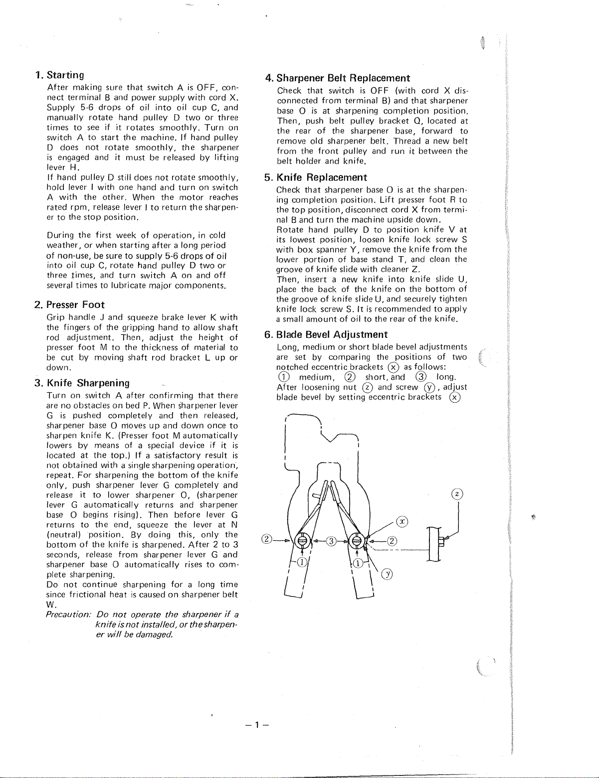
6.
Blade
Long,
are
notched
After
blade bevel by
is
is
3
a
rear
the
holder
completion
top
Band
box
the
groove
set
G)
medium,
loosening
that
switch
from
terminal
is
at
sharpening
push
belt
of
the
old
sharpener
front
pulley and
and
knife.
that
sharpener
position,
hand
portion
of
insert a new
amount
Bevel
medium
position.
turn
the
pulley D
position,
spanner
of
knife
slide
back
of
of
knife slide U,
of
Adjustment
or
by
comparing
eccentric
disconnect
S.
@
nut
setting
is
OFF
pulley
bracket
sharpener
belt.
base 0
machine
to
loosen
Y,
remove
base
stand
with
knife
the
knife
It
is
recommended
oil
to
the
short
blade bevel
the
brackets
short,
® and
eccentric
(with
cord
B)
and
that
completion
0,
base,
forward
Thread a new
run
it
between
is
at
the
Lift presser
cord X
upside
position
knife
cleaner
into
and
rear
down.
lock screw S
the
knife
T,
and
Z.
knife
on
the
securely
of
the
adjustments
positions
from
knife V at
0 as follows:
and
G)
screw
(j),
brackets
X dis-
sharpener
position.
located
belt
sharpen-
foot R to
termi-
from
the
clean
the
slide U,
bottom
tighten
to
apply
knife.
of
two
long.
adjust
0
at
to
the
of
-1-
H
E
A
CD
ie\
\j
c
__
~
X \
s
w
R
5-6
oil
c
Daily
drops
in
oil
of
cup
Weekly
1. 0
2.
@)
@
3.
0
(')
Lubrication
(Lubrication)
and®
Sharpener
(indicated by
arrow
Upper
rear
mark)
belt
Pipes
base
holes
pulley
on
Monthly
1.
@Remove
red.
2.
®Remove
cover and grease
slide
(Greasing)
screw
clutch
shafts.
J
K
0
@
T
u
v
in
z
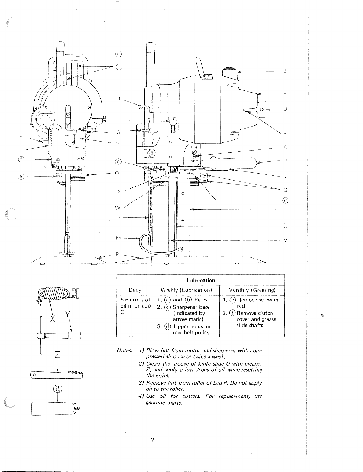
Notes:
i
1)
Blow
lint
pressed
2)
Clean the groove
Z,
the knife.
3)
Remove
oil
4)
Use
genuine parts.
air
and
applv a few
lint
to
the roller.
oil
from
once
for
motor
or
of
from
cutters.
and
sharpener
twice a week.
knife
slide U
drops
of
roller
of
bed
For
oil
replacement,
-2-
with
com-
with
cleaner
when resetting
P.
Do
not
applv
use
SC14A
\
\ \
~~©
SC14B
(
SC21B
I
~
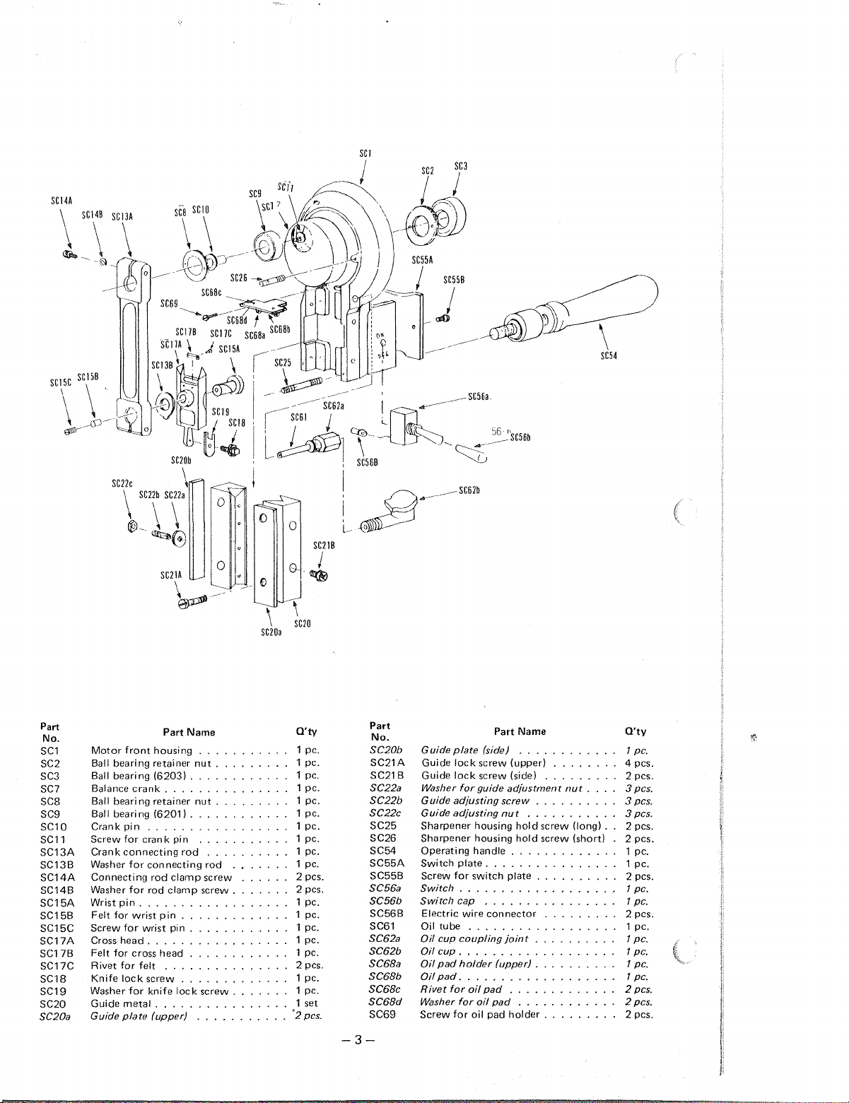
Part
No.
SC1
SC2
SC3
SC7
scs
SC9
SC10
SC11
SC13A
SC13B
SC14A
SC14B
SC15A
SC15B
SC15C
SC17A
SC17B
SC17C
SC18
SC19
SC20
SC20a
Motor
front
Ball
bearing retainer
Ball
bearing
Balance
crank
Ball
bearing retainer
Ball
bearing (6201) .
Crank
pin
Screw
for
Crank
Washer
Connecting
Washer
Wrist
Felt for wrist
Screw
Cross
Felt for cross
Rivet for felt
Knife
Washer
Guide
Guide
crank
connecting
for
for
pin
.
for
wrist pin .
head.
lock
screw
for
metal
plate
Name
Part
housing
(6203) .
. . . .
. .
pin
rod
connecting
rod
clamp
rod
clamp
. .
. .
pin
.
head
knife
lock
.
(upper)
. .
nut
nut
rod
screw
screw .
screw
. .
O'ty
1 pc.
. .
1 pc.
1 pc.
1 pc.
1 pc.
1 pc.
1 pc.
1 pc.
1 pc.
1 pc.
2 pes.
2 pes.
1 pc.
1 pc.
1 pc.
1 pc.
1 pc.
2 pes.
1 pc.
1 pc.
1 set
'2pcs.
.
.
.
. .
. .
Part
No.
SC20b
SC21A
SC21B
SC22a
SC22b
SC22c
SC25
SC26
SC54
SC55A
SC55B
SC56a
SC56b
SC56B
SC61
SC62a
SC62b
SC68a
SC68b
SC68c
SC68d
SC69
Guide
plate
Guide
lock
lock
Guide
Washer
for
Guide
adjusting
Guide
adjusting
Sharpener
Sharpener
Operating
Switch
plate.
Screw
for
tube
cup
cup.
pad
pad.
for
switch
..
cap
..
coupling
holder
oil
for
for
oil
Switch
Switch
Electric wire
Oil
Oil
Oil
Oil
Oil
Rivet
Washer
Screw
Part Name
(side J
screw
(upper)
screw (side)
guide
adjustment
screw
nut
housing
housing
handle .
plate
. . . . . .
. . . . . . . . . . . . . 1
connector
. . . . .
joint
.
..
. .
(upper)
...
. . . . . . . . . . .
pad
oil
pad
pad
holder
-3-
. . . .
. .
. . . . . .
. . .
hold
screw
hold
screw (short)
. . .
...
..
..
..
. . .
.
..
.....
.....
..
. . . .
nut
. . . .
(long) .
..
. .
. . . .
..
. .
. .
. .
. . .
. . 1
. .
.
. .
. .
. .
. . 2 pes.
.
...
O'ty
pc
4 pes.
2 pes .
3pcs
3pcs
3pcs
2 pes .
2 pes.
1 pc.
1
pc
1
pc
pc
2 pes.
1 pc.
1
pc.
1 pc.
1 pc.
1 pc.
2 pes.
2pcs.
2 pes.
.
~
.
.
.
.
.
.
 Loading...