

Conner CFS270A REV A product manual

CFS270A
Intelligent Disk Drive
Product Manual
Production Release Per ECO 6379
P/N 20401000-001
Revision A
May 1995
3081 Zanker Road
San Jose, CA 95134-2128
(408) 456-4500


FCC Notice
This equipment generates and uses radio frequency energy and, if not installed
and used properly; that is, in strict accordance with the manufacturer's
instructions, may cause interference to radio and television reception. It has
been type tested and found to comply with the limits for a Class B computing
device in accordance with the specifications in Part 15 of FCC Rules, which are
designed to provide reasonable protection against such interference in a
residential installation. However, there is no guarantee that interference will
not occur in a particular installation. If this equipment does cause interference
to radio or television reception, which can be determined by turning the
equipment on and off, you are encouraged to try to correct the interference by
one or more of the following measures:
• Reorient the receiving antenna.
• Relocate the computer with respect to the receiver.
• Move the computer into a different outlet so that the computer and receiver
are on different branch circuits.
If necessary, you should consult the dealer or an experienced radio/television
technician for additional suggestions. You may find the following booklet
prepared by the Federal Communications Commission helpful:
How to Identify and Resolve Radio-TV Interference Problems
This booklet (Stock No. 004-000-00345-4) is available from the U.S. Government
Printing Office, Washington, DC 20402.
Warning: Changes or modifications made to this equipment which have not
been expressly approved by Conner Peripherals, Inc. may cause radio and
television interference problems that could void the user's authority to operate
the equipment.
Further, this equipment complies with the limits for a Class B digital apparatus
in accordance with Canadian Radio Interference Regulations.
Cet appareil numérique de la classe B est conforme au Règlement sur le
brouillage radioélectrique, C.R.C., ch. 1374.
Conner and the Conner logo are registered trademarks of Conner Peripherals,
Inc. All other trademarks mentioned in this manual are property of their
respective owners.
Copyright 1994, Conner Peripherals, Inc.
All rights reserved.
Document No. 501-078 04/95

Important Information About this Manual
All information contained in or disclosed by this document is considered
proprietary by Conner Peripherals, Inc. By accepting this material, the recipient
agrees that this material and the information contained therein are held in
confidence and in trust and will not be used, reproduced in whole or in part, nor
its contents revealed to others, except to meet the purpose for which it was
delivered. It is understood that no right is conveyed to reproduce or translate
any item herein disclosed without express written permission from Conner
Peripherals, Inc.
Conner Peripherals, Inc. provides this manual "as is," without warranty of any
kind, either expressed or implied, including, but not limited to, the implied
warranties of merchantability and fitness for a particular purpose. Conner
Peripherals, Inc. reserves the right to change, without notification, the
specifications contained in this manual.
Conner Peripherals, Inc. assumes no responsibility for the accuracy,
completeness, sufficiency, or usefulness of this manual, nor for any problem that
might arise from the use of the information in this manual.

Table of Contents
1. Overview of the Drive 1
2. Specifications 5
What is the Drive? 1
Features of the Drive 1
What the Drive is Composed Of 2
Mechanical Design Features 2
Drive Assembly Housing 2
Head Positioning Mechanism 2
Read/Write Heads and Disks 3
Data and Power Connections 4
Electrical Design Features 4
Pre-amplifier 4
Circuit Board 4
Firmware 4
Specifications In This Chapter 5
Drive Capacity 6
Physical Configuration 6
Performance Characteristics 7
Read/Write Characteristics 8
Reliability 8
Power Requirements 9
Environmental Tolerances 9
Safety Standards 10
Physical Characteristics 11
3. How the Drive Operates 13
Functions of the Drive 13
Drive Operational Modes 13
Error Correction 13
Universal Translate Mode 14
Master/Slave Configuration 14
Cable Select 15
4. Installing the Drive 17
Take These Precautions 17
Installing the Drive 17
Attaching a Data Cable to the Drive 19
Attaching Power to the Drive 21
Mounting the Drive 22
Technical Reference Manual Page i

Table of Contents Filepro CFS210A/CFS420A
5. Host Interface 23
About the Host Interface 23
Signal Conventions 23
Signal Levels 23
Signal Descriptions 24
ATA/CAM Master/Slave Reset Timing 26
Host PI0 16-Bit Timing Values 28
Host Demand Mode DMA 16-bit Interface Timing Values 29
6. Register Addresses and Functions 31
Host Address Decoding 31
Descriptions of the Registers 33
Data Register 33
Error Register 34
Features Register (formerly Write Precomp Register) 35
Sector Count 35
Sector Number 35
Cylinder Low 36
Cylinder High 36
SDH Register 37
Status Register 38
Alternate Status Register 39
Digital Output Register 40
Drive Address Register 41
Command Register 41
7. Command Set 45
Command Register 45
Conner Specific 46
Get Drive Feature word (00) 47
Read the Drive Switches (02) 48
Power Lock (08) 48
Power Unlock (09) 48
Execute Device Diagnostic 49
Format Track 50
Marked Bad Sector 50
Assign 50
Identify Device 52
Initialize Device Parameters 55
Power Commands 56
Read DMA 57
Read Multiple 58
Read Sector(s) 59
Read Sector Buffer 60
Read Verify Sectors 61
Recalibrate 61
Seek 62
Set Features (Set Look Ahead Read) 63
Set Multiple Mode 63
Write DMA 64
Write Caching 64
Write Multiple 65
Page ii Filepro CFS270A

Filepro CFS270A Table of Contents
Write Caching 66
Write Sector(s) 67
Write Caching 68
Write Sector Buffer 69
8. Error Reporting 71
Error and Status Detection 71
Error and Status Messages 71
Technical Reference Manual Page iii

Table of Contents Filepro CFS210A/CFS420A
Page iv Filepro CFS270A

Overview of the Drive
Capacity (formatted):
270MB
What is the Drive?
The Conner Filepro Series CFS270A is a high-performance, low-profile hard disk
drive that is designed to operate with an IBM PC/AT or equivalent host
computer system in translate mode.
1
Drive Model: Form Factor:
CFS270A inch high, 3.5 inch
Features of the Drive
The drive provides these features:
• can be installed in a wide range of host systems
• high-performance rotary voice coil actuator with embedded servo
• one-of-seven run-length limited code
• high shock resistance
• automatic actuator latch against inner stop upon power-down
• microprocessor-controlled diagnostic routines that are automatically
executed at start-up
• 32KB/64KB buffer with adaptive cache management
No. of disks/heads:
1 disk/2 heads
Technical Reference Manual Page 1
• Read Look Ahead and Write Caching
• automatic error correction and retries, ECC on the fly
• 512-byte block size
• emulates IBM Task File and supports additional commands
• allows daisy-chaining up to two drives on the AT interface
• Auto-Translate (Universal Translate)
• 4-byte ECC diagnostic check in read/write
• Supports the ATA (AT Attachment) Interface Standard

Chapter 1 Overview of the Drives
What the Drive is Composed Of
The drive is composed of mechanical, electrical, and firmware elements.
Mechanical Design Features
The drive’s hardware includes the components described in the following
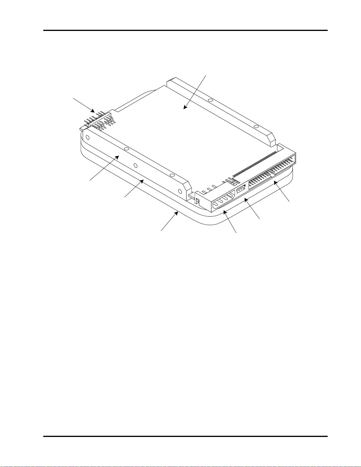
sections. Figure 1-1 shows some of these components.
Drive Assembly Housing
The drive assembly housing consists of an extruded aluminum base on which is
mounted a drawn aluminum cover. In addition, the aluminum cover has a
designed in breather filter and diffusion tube that prevents entry of
contaminants which might degrade head and media reliability. Aluminum tape
seals the joint between the base and cover. Critical drive components are
contained within this contaminant-free environment, which is commonly
referred to as the Head-Disk Assembly (HDA).
Drive Motor and Spindle
A brushless DC direct-drive motor assembly is mounted on the drive’s base. The
motor rotates the drive’s spindle at 3400 RPM. The motor/spindle assembly is
dynamically balanced to provide minimal mechanical runout to the disks. A
dynamic brake is used to provide a fast stop to the spindle motor and return the
heads to the landing zone when power is removed.
Head Positioning Mechanism
The read/write heads are supported by a mechanism coupled to a rotary voice
coil actuator.
Page 2 Filepro CFS270A
Overview of the Drives Chapter 1
Figure 1-1
Hard Drive Components
Printed Circuit
Board Assembly
Jumpers
Extruded Base
Aluminum Tape
Seal
Drawn Aluminum
Cover
3-Pin Power
Connector
Standard 4-Pin
Power Connector
40-Pin Data Connector
(Task File Interface)
Read/Write Heads and Disks
Data is recorded on a 95mm diameter disk using Metal In Gap (MIG) composite
heads.
The CFS270A contains:
• one disk with two data surfaces
• two read/write heads
At power-down, the heads are automatically retracted to the inner diameter of
the disk and are latched and parked on a landing zone that is separate from the
data tracks.
Technical Reference Manual Page 3

Chapter 1 Overview of the Drives
Data and Power Connections
The drive has a single 40-pin data connector, as well as an auxiliary connector
which is reserved for factory or evaluation use.
The drive has two power connectors, only one of which should be used at a time.
The two connectors provide connection versatility to a number of host systems.
The drive also has a jumper block which can be set to specify drive operational
parameters. For more information on the drive’s connectors and on setting
jumpers, refer to chapters 3 and 4.
Electrical Design Features
Pre-amplifier
A single integrated circuit (IC) is mounted within the head disk assembly, in
close proximity to the read/write heads. The IC provides head selection, read
pre-amplification, and write drive circuitry.
Firmware
Circuit Board
The drive’s microprocessor-controlled circuit board provides the remaining
electronic functions, which include:
• read/write circuitry
• rotary actuator control
• interface control
• spin speed control
• auto-park
• power management
The drive’s firmware includes a command set which the host uses to control the
drive. The command set allows the host to request the following types of actions:
• report drive status
• seek a specific point on the disk
• read and write data
For more information on the drive’s command set, refer to chapters 6 and 7.
Page 4 Filepro CFS270A

Specifications
Specifications In This Chapter
This chapter defines the following specifications for the drive:
• drive capacity
• physical configuration
• performance characteristics
• read/write characteristics
• reliability
• power requirements
• environmental tolerances
• safety standards
• physical characteristics
2
Technical Reference Manual Page 5

Chapter 2 Specifications
Drive Capacity
Formatted Capacity:
• CFS270A: 270.9MB
* 1MB = 1 x 106 bytes
Physical Configuration
Specification CFS270A:
Disk Type
Head Type
Actuator Type
Number of Disks
Data Surfaces
Data Heads
Servo
Tracks per Surface
Buffer Size
Track Density
Formatted Track Capacity
Bytes per Block
Blocks per Drive
Sectors per Track (User)
Translate
* Refer to chapter 3 for a definition of Universal Translate Mode
Sputtered Thin Film
MIG
Rotary Voice Coil
1
2
2
Embedded
2595
32KB
2988 tpi
36,864-59,904 bytes
512
529,200
71-116
Universal
Page 6 Filepro CFS270A

Specifications Chapter 2
Performance Characteristics
Seek Times (typical)* :
• Track to track: 3.0 ms
• Average: 14 ms **
• Maximum: 28 ms
• The timing is measured through the interface with the drive operating at nominal DC input
voltage and nominal operating temperature. The timing also assumes that:
• BIOS and PC system hardware dependency have been subtracted from timing measurements
• the drive is operated using its native drive parameters
• the controller overhead is the time it takes to assert +HOST IRQ after the host writes the
command register with a READ instruction, for the case where the data already resides in the
buffer
** The average seek time is determined by averaging the seek time for a minimum of 1000 seeks
of random length over the surface of the disk.
Average Latency:
• 8.8 ms
Rotation Speed:
• 3400 RPM (+ 0.1%)
Controller Overhead:
• <1.0ms
Start Time at Power-Up: *
• 0 RPM to 3400 RPM
- Typical: 6 seconds
- Maximum: 10 seconds
• 0 RPM to Ready
- Typical: 15 seconds
- Maximum: 20 seconds
* These numbers assume spin recovery is not invoked. If spin recovery is invoked, the
maximum could be 40 seconds. Briefly removing power can lead to spin recovery being
invoked.
Stop Time at Power-Down:
• Typical: 15 seconds
• Maximum: 20 seconds
Interleave:
• 1:1
Technical Reference Manual Page 7

Chapter 2 Specifications
Read/Write Characteristics
Interface:
• Task File
Recording Method:
• 1 of 7 RLL code
Recording Density (ID):
• 68,000 bits per inch
Flux Density (ID):
• 51,000 flux reversals per inch
Data Transfer Rate:
• To/From Media: 2.53 - 4.35 MB/second
• To/From Host: PIO Mode 3 (11.1 MB/second) or Multiword DMA Mode 1
(13.3 MB/second)
Reliability
Data Reliability:
• < 1 non-recoverable error in 10
Component Design Life:
• 5 years
Start/Stop Cycles:
• 20,000 minimum
Mean Time Between Failures:
• 250,000 power-on hours
Mean Time to Repair:
• 10 minutes typical
Preventive Maintenance:
• none
14
bits read
Page 8 Filepro CFS270A

Specifications Chapter 2
Power Requirements
+5 Volts
Mode: *
Read/Write
Seek/Rd/Wr
Idle
Standby
Sleep
Spin-Up
* Refer to chapter 3 for the definitions of the modes. Spin-Up Mode current draw is for 7 seconds,
maximum. Maximum power is when the supply voltage is at the worst case condition.
(typical):
400 mA 150 mA 3.8 W 4.0 W
340 mA 120 mA 3.1 W 4.5 W
200 mA 125 mA 2.5 W 3.0 W
120 mA 0 mA 0.6 W <1.0 W
100 mA 0 mA 0.5 W <1.0 W
400 mA 1000 mA N/A N/A
+12 Volts
(typical):
Watts
(typical):
(maximum):
Minimum/Maximum Voltage:
• +5V: +5%
• +12V: +5%
Maximum Peak-to-Peak Noise Allowed (DC to 1 MHz, with equivalent
resistive load):
• +5V: 2%
• +12V: 1%
Environmental Tolerances
Temperature:
• Operating: 5° to 55° C
• Non-operating: -40° to 60° C
• Thermal Gradient: 20
Relative Humidity (non-condensing):
• Operating: 8 to 80%
• Non-operating: 8 to 80%
• Wet Bulb: 28.9
Altitude (relative to sea level):
• Operating: -200 to 10,000 feet
• Non-operating:-200 to 40,000 feet (maximum)
• Altitude Gradient: 1,000 feet/minute
Shock (half-sine pulse, 11 ms duration):
• Operating: 5G without non-recoverable errors
• Non-operating: 75G without non-recoverable errors
o
C per hour maximum
o
C maximum
Technical Reference Manual Page 9

Chapter 2 Specifications
Vibration (swept-sine, one octave per minute):
• Operating
− 5 - 22 Hz: 0.020 inch displacement; double amplitude, 1 octave per
minute.
− 22 - 400 Hz: 0.5G peak without non-recoverable errors
• Non-operating
− 5 - 22 Hz: 0.20 inch displacement; double amplitude, 1/2 octave per
minute
− 22 - 400 Hz: 5G peak
Magnetic Field:
• The disk drive will meet its specified performance while operating in the
presence of an externally-produced magnetic field under the following
conditions:
Field Frequency Intensity
Acoustic Noise:
• The sound pressure level will not exceed 34 dBA in Idle Mode at a distance
Safety Standards
The drive is designed to comply with relevant product safety standards,
including:
• UL 478, 5th edition, Standard for Safety of Information Processing and
• UL 1950, Standard for Safety of Information Technology Equipment
• CSA 22.2 #220, Information Processing and Business Equipment
• CSA 22.2 #950, Safety of Information Technology Equipment
DC
to 700 Khz
700 Khz to 1.5 Mhz
of 1 meter from the drive. The sound power level measured based on ISO
7779 will not exceed 4.0 Bel in Idle Mode.
Business Equipment
6 gauss
7 milligauss
3 milligauss
• IEC 380, Safety of Electrically Energized Office Machines
• IEC 950, Safety of information Technology Equipment Including Electrical
Business Equipment
• VDE 0805, VDE 0805 TIEL 100, and VDE 0806
• Complies with FCC Class B, Part 15, Subpart J
Page 10 Filepro CFS270A
Specifications Chapter 2
Physical Characteristics
Height:
• 1.0 inch + .030
Width:
• 4.0 inches + .030
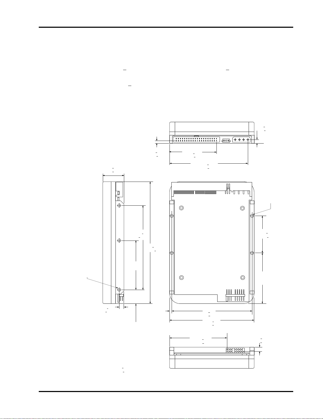
Figure 2-1
The Drive’s Physical Dimensions
0.18 +.015
[4.572 +.381]
1.00 +.03
[25.4 +.762]
Depth:
• 5.75 inches + .030
Weight:
• 1.1 pounds
2.227 +.03-
[56.565 +.762]
3.716 +.03
[94.386 +.762]
0.23 +.015
[5.842 +.381]
4X 6-32 UNC-2B
.25 MAX. INSERTION
[6.35]
3x 6-32 UNC-2B
.25 MAX. INSERTION
[6.35]
BOTH SIDES
3x.250 + .015
[6.35 +.381]
BOTH SIDES
Note: [mm]
.xx + .01
.xxx + .005
4.000+
[101.6+ .254]
2.362 +.01
[59.994+ .254]
+.03
.630
- .005
+.762
[16.0 ]
- .127
.01
5.75 +.03
[146.05 +.762]
+.03
.125
- .005
[3.175 ]
+.762
- .127
3.750 +.01
[95.25+.254]
4.00 +.03
[101.6 +.762]
2.645 +.03
[67.183 +.762]
1.750+.01
[44.45+.254]
2.375
[60.325 ]
0.172 +.015
[4.368 +.381]
+.03
- .005
+.762
- .127
Technical Reference Manual Page 11

Chapter 2 Specifications
Page 12 Filepro CFS270A

How the Drive Operates
Functions of the Drive
This chapter describes certain operational aspects of the drive, including
discussions of:
• drive operational modes
• error correction
• Universal Translate Mode
• master/slave configurations
Drive Operational Modes
The drive operates in the following modes:
• Read/Write Mode occurs when data is read from or written to the disk.
• Seek/Rd/Wr Mode occurs when the drive is operated in a random seeking
read/write mode with a 30% seek duty cycle.
• Idle Mode occurs when the drive is not reading, writing, or seeking. The
motor is up to speed and the Drive Ready condition exists. The actuator is
residing on the last-accessed track.
3
Error Correction
• Standby Mode occurs when the motor is stopped and the actuator is
parked. Standby Mode occurs after a programmable time-out since the last
host access occurs. The drive will leave Standby Mode upon receipt of a
command which requires disk access, or upon receipt of a spin-up command.
• Sleep Mode occurs when all electronics are disabled. The host is required
to issue a Reset command to exit the Sleep Mode.
• Spin-Up Mode occurs while the drive is spun up to speed after being
powered on or after exiting Standby or Sleep Mode.
The drive uses a Reed-Solomon code to perform error detection and correction.
For each 512-byte block, the software error correction polynomial is capable of
correcting:
• one error burst up to 22 bits
• two error bursts up to 11 bits each
Single bursts of 11 bits or less are corrected on the fly (OTF) with no
performance degradation.
Technical Reference Manual Page 13

Chapter 3 How the Drive Operates
No. of
Sectors:
63
Universal Translate Mode
Conner has established a Universal Translate Mode which enables you to
configure the drive in an AT environment to any cylinder, head, and sector
configuration desired. The translate configuration is limited by the maximum
capacity of the drive and host system parameters. Upon initial power-up of the
drive, it will default to the configuration shown below:
No. of
Drive:
Cylinders:
No. of Heads
CFS270A
Note: Some early production drives may have a default translate of 525 cylinders, 16 heads,
63 sectors.
After the drive is ready, the host system may issue an Initialize Device
Parameters command (command code 91
configuration (number of heads and number of sectors per track). The drive will
then:
• calculate the total number of available logical tracks based upon the entered
sector and head values
• save the drive parameters in non-volatile memory for subsequent drive
operations
Master/Slave Configuration
When two drives are daisy-chained on the host interface, one must be designated
as the master drive (C: drive) and one as the slave drive (D: drive).
Commands from the host are written in parallel to both drives.
When the C/D jumper on the drive is closed, the drive will assume the role of a
master. When C/D is open, the drive will act as a slave. In single-drive
configurations, C/D must remain in the closed (master) position. For more
information on setting the C/D jumper, refer to chapter 4.
600 14
hex) to alter the translate
For each command sent from the host, the DRV bit in the Device/Head register
selects the master or the slave drive. When the DRV bit is reset (0), the master
drive is selected, and when the DRV bit is set (1), the slave drive is selected.
Once the drives receive the command, only the drive with jumper C/D set to the
appropriate position will execute the command. For example, if the DRV bit is
set, only the slave drive (jumper C/D open) will execute the command.
☞☞ Note: If the command is a diagnostic command, both drives will execute the command and the
slave will report its status to the master via the Host PDIAG signal.
Throughout this manual, drive selection always refers to the state of the DRV
bit and the position of the C/D jumper.
Page 14 Filepro CFS270A

How the Drive Operates Chapter 3
Cable Select
This optional method of drive Master/Slave designation can be enabled by
jumper selection as described in Chapter 4. If used, special cabling can be used
to selectively ground CSEL of the drive intended to be drive C (0). This drive
will then function as the Master. If CSEL is allowed to float the drive will
recognize itself as drive D (1) and function as the Slave.
Technical Reference Manual Page 15

Chapter 3 How the Drive Operates
Page 16 Filepro CFS270A

Installing the Drive
Take These Precautions
Installing the Drive
To install the drive, you must:
4
To protect your equipment from electrostatic damage,
perform the installation at a static-safe workstation. If one is
not available, follow these guidelines:
1. Work in an uncarpeted area.
2. Before removing the equipment from its anti-static bag,
discharge static electricity by touching your computer's
metal chassis (or any other grounded object) while
touching the anti-static bag.
3. Do not touch circuit boards unless instructed to do so.
0170
• set the drive’s jumpers, if desired
• attach a data cable to the drive
• attach power to the drive
• mount the drive
Technical Reference Manual Page 17
 Loading...