

Page 1

CFP1080S/CFP1080E
Intelligent Disk Drive
Product Manual
Production Release Per ECO 6561
P/N 20401007-001
Revision A
August 1995
3081 Zanker Road
San Jose, CA 95134-2128
(408) 456-4500
Page 2

Page 3

FCC Notice
This equipment generates and uses radio frequency energy and, if not installed
and used properly; that is, in strict accordance with the manufacturer's
instructions, may cause interference to radio and television reception. It has
been type tested and found to comply with the limits for a Class B computing
device in accordance with the specifications in Part 15 of FCC Rules, which are
designed to provide reasonable protection against such interference in a
residential installation. However, there is no guarantee that interference will
not occur in a particular installation. If this equipment does cause interference
to radio or television reception, which can be determined by turning the
equipment on and off, you are encouraged to try to correct the interference by
one or more of the following measures:
• Reorient the receiving antenna.
• Relocate the computer with respect to the receiver.
• Move the computer into a different outlet so that the computer and receiver
are on different branch circuits.
If necessary, you should consult the dealer or an experienced radio/television
technician for additional suggestions. You may find the following booklet
prepared by the Federal Communications Commission helpful:
How to Identify and Resolve Radio-TV Interference Problems
This booklet (Stock No. 004-000-00345-4) is available from the U.S. Government
Printing Office, Washington, DC 20402.
Warning: Changes or modifications made to this equipment which have not
been expressly approved by Conner Peripherals, Inc. may cause radio and
television interference problems that could void the user's authority to operate
the equipment.
Further, this equipment complies with the limits for a Class B digital apparatus
in accordance with Canadian Radio Interference Regulations.
Cet appareil numérique de la classe B est conforme au Règlement sur le
brouillage radioélectrique, C.R.C., ch. 1374.
Conner and the Conner logo are registered trademarks of Conner Peripherals,
Inc. All other trademarks mentioned in this manual are property of their
respective owners.
Copyright 1994,1995 Conner Peripherals, Inc.
All rights reserved.
Document No. 501-082 08/95
Page 4

Important Information About this Manual
All information contained in or disclosed by this document is considered
proprietary by Conner Peripherals, Inc. By accepting this material, the recipient
agrees that this material and the information contained therein are held in
confidence and in trust and will not be used, reproduced in whole or in part, nor
its contents revealed to others, except to meet the purpose for which it was
delivered. It is understood that no right is conveyed to reproduce or translate
any item herein disclosed without express written permission from Conner
Peripherals, Inc.
Conner Peripherals, Inc. provides this manual "as is," without warranty of any
kind, either expressed or implied, including, but not limited to, the implied
warranties of merchantability and fitness for a particular purpose. Conner
Peripherals, Inc. reserves the right to change, without notification, the
specifications contained in this manual.
Conner Peripherals, Inc. assumes no responsibility for the accuracy,
completeness, sufficiency, or usefulness of this manual, nor for any problem that
might arise from the use of the information in this manual.
Page 5

Table of Contents
1. Drive Overview 1
2. Specifications 9
Drive Description 1
Drive Features 2
Drive Components 3
Mechanical Design Features 3
Drive Assembly Housing 4
Drive Motor and Spindle 5
Head Positioning Mechanism 5
Read/Write Heads and Disks 5
Data and Power Connections 5
Electrical Design Features 5
Integrated Circuit 5
Circuit Board 5
Read/Write Channel 6
Firmware 6
Specifications in this Chapter 9
Drive Capacity 10
Formatted Capacity 10
Physical Configuration 10
Physical Configuration per Zone 10
Performance Characteristics 11
Seek Times (typical)
Average Latency 11
Rotation Speed (+0.1%) 11
Controller Overhead
Start Time(Power Up)
Stop Time at Power Down 11
Interleave 11
Read/Write Characteristics 12
Recording Method 12
Recording Density (maximum) 12
Flux Density (maximum) 12
SCSI Characteristics 12
Command Set 12
Data Transfer Rate 12
Maximum Synchronous Transfer Offset: 12
Maximum Tagged Command Queue Depth: 12
Reliability 13
Data Reliability 13
Component Design Life 13
Start/Stop cycles 13
Mean Time Between Failures: 13
Mean Time to Repair 13
Preventive Maintenance 13
Power Requirements 13
Minimum/Maximum Voltage: 13
Environmental Tolerances 14
Magnetic Field: 14
1
3
4
11
11
11
Technical Reference Manual Page i
Page 6

Table of Contents Conner CFP1080E/CFP1080S
Acoustic Noise: 14
Safety Standards 15
Physical Characteristics - CFP1080E 16
Physical Characteristics - CFP1080S 17
3. Drive Operation 19
Drive Functions 19
Drive Operational Modes 19
Error Correction 20
Read Retry Operations 20
Downloadable Microcode 21
Buffer Management and Command Execution 22
SCSI Look Ahead Control Code 22
Write Caching 24
SCSI Queuing Control Code 25
Command Re-ordering 25
Buffer Management 25
4. Installing the Drive 27
Take These Precautions 27
Installing the Drive 27
Installing a CFP1080E 28
Setting the Drive's Jumpers - CFP1080E 28
Setting the SCSI Bus Address - CFP1080E 28
Disabling Spin-Up at Power On - CFP1080E 29
Delaying Spin Up at Power On - CFP1080E 29
Host Interface Connection - CFP1080E 29
Attaching Power to the Drive - CFP1080E 31
Mounting the Drive - CFP1080E 31
Installing a CFP1080S 32
Setting the Drive's Jumpers - CFP1080S 32
Setting the SCSI Bus Address - CFP1080S 33
Disabling Spin-Up at Power On - CFP1080S 34
Disabling SCSI Bus Terminator Power (TERMPWR) -
CFP1080S 34
Setting the Bus Termination - CFP1080S 35
Cabling the Drive - CFP1080S 36
SCSI Bus Cable 36
Spindle Synchronization 36
Attaching Power to the Drive - CFP1080S 37
Attaching a Remote LED - CFP1080S 37
Mounting the Drive - CFP1080S 37
5. Interface Physical Characteristics 39
Electrical Description 39
Output Characteristics 39
Input Characteristics 40
Model-Specific SCSI Physical Characteristics 40
CFP1080E (WIDE, 80-pin Single Connector Attachment [SCA]) 41
External Terminator Power 41
Internal Termination 41
Cable Requirements 41
Page ii Conner CFP1080E/CFP1080S
Page 7

Conner CFA850/CFA1275 Table of Contents
Connector Requirements 42
Single Connector Attachment (SCA) Signal Definitions 42
Power 42
Spindle Sync 42
LED Out 42
Motor Start Controls 43
SCSI ID Selection 43
Interface Pin Assignments 44
Model CFP1080S (Narrow, 50-pin SCSI) 45
External Terminator Power 45
Internal Termination 45
Cable Requirements 46
Connector Requirements 47
Interface Pin Assignments 48
Interface Timing Requirements 49
6. SCSI Command Implementation 51
SCSI Command Summary 51
Drive Dependent SCSI Mode Sense Data 51
Format Device Page - 03
Rigid Disk Geometry Page - 04
Notch Page - 0C
H
H
H
52
54
55
Technical Reference Manual Page iii
Page 8

Table of Contents Conner CFP1080E/CFP1080S
Page iv Conner CFP1080E/CFP1080S
Page 9

Drive Overview
Drive Description
The CFP1080S and CFP1080E are high performance 3.5-inch low-profile (1.0
inch high) disk drives. The both offer 11 millisecond average seek time for
Reading, 11.5 millisecond seek time for Writing, with an average latency of only
5.56ms. High capacity is achieved by utilizing a zone density recording
technique using 8 recording zones at an areal density of 247 Mbits per square
inch. These drives feature high performance while maintaining low power
consumption to reduce power supply current and system cooling requirements in
disk arrays.
They are designed to operate on the Small Computer System Interface (SCSI)
and are SCSI-2 command compatible. The mechanical and major electronic
components are identical between the models and differ only in the SCSI
physical interface.
Drive Model Form Factor Interface Capacity
CFP1080S
CFP1080E
1
1 inch high, 3.5 inch
1 inch high, 3.5 inch 80-pin Single Ended FAST 1080MB
50-pin Single Ended FAST
1080MB
For simplicity, we often refer to these drives collectively in this manual as “the
drive.”
Technical Reference Manual Page 1
Page 10

Chapter 1 Overview of the Drives
Drive Features
The drives provide the following features:
• 256 KB segmented cache buffer in the CFP1080S and 512 KB segmented
cache buffer in the CFP1080E.
• Tagged Command Queuing with Minimum Access Time Re-ordering and
Write/Read Coalescing
• Down-loadable Code through SCSI Interface
• SCSI-2 Compatibility
• 88 bit Reed-Solomon EDAC with on the fly error correction
• Microprocessor-controlled diagnostic routines execute at start-up
• Automatic Spindle Synchronization
• Voltage Regulated Termination Power with removable Resistor Packs (SCSI-
2, Alternative 2)
• Active Negation output drivers
• High performance rotary voice coil actuator with embedded servo system
• No thermal recalibration required to maintain performance levels
• High Shock resistance
• Automatic actuator latch against the inner stop upon power down with
dedicated landing zone
• Sealed HDA
• 1,7 run length limited code
Page 2 Conner CFP1080E/CFP1080S
Page 11
Overview of the Drives Chapter 1
Drive Components
The drive is composed of mechanical, electrical, and firmware elements.
Mechanical Design Features
The drive’s hardware includes the components described in the following
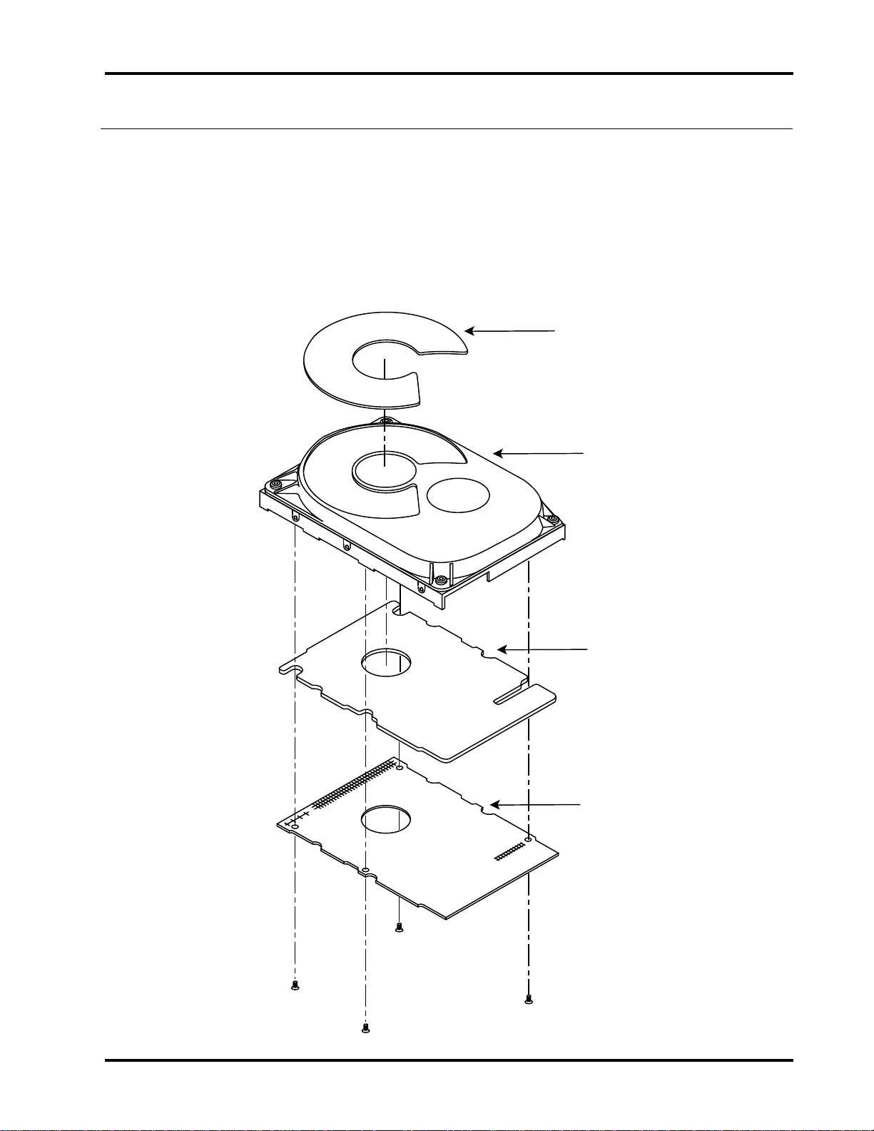
sections. Figure 1-1 shows the drive top level assembly.
Figure 1-1
Drive Top Level Assembly
Damper
Head-Disk
Assembly
Printed Circuit
Board Assembly
Shield
Printed
Circuit
Board
Assembly
Technical Reference Manual Page 3
Page 12
Chapter 1 Overview of the Drives
Drive Assembly Housing
The drive assembly housing, or Head-Disk Assembly (HDA) consists of a die-cast
aluminum base on which is mounted a die-cast aluminum cover. Both the base
and the cover are fabricated using an alloy and surface finishing process
designed to inhibit oxidation. A gasket seals the joint between the base and
cover to retard the entry of moisture and environmental contaminants from the
assembly.
This assembly, the head-disk assembly (HDA), contains an integral 0.3 micron
filter, which maintains a clean environment. Critical drive components are
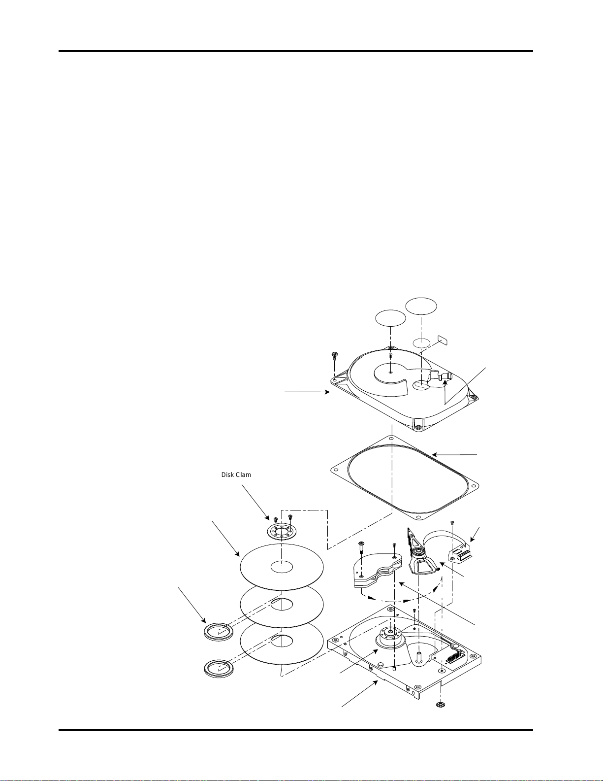
contained within this contaminant-free environment. Figure 1-2 shows the HDA
and the major assemblies contained within it:
Figure 1-2
Head-Disk Assembly
Disk (1 of 3)
Disk
Spacer (1 of 2)
Disk Clamp
Top Cover
Filter
Gasket
Preamplifier/
Flex Circuit
Assembly
Head-Stack
Assembly
Actuator
Magnet
Assembly
Spindle Motor
Base Assembly
080S_1_2
Page 4 Conner CFP1080E/CFP1080S
Page 13

Overview of the Drives Chapter 1
Drive Motor and Spindle
A brushless DC direct-drive motor assembly is mounted on the drive’s base. The
motor rotates the drive’s spindle at 5400 RPM. The motor/spindle assembly is
dynamically balanced to provide minimal mechanical runout to the disks. A
dynamic brake is used to provide a fast stop to the spindle motor and return the
heads to the landing zone when power is removed.
Head Positioning Mechanism
The read/write heads are supported by a mechanism coupled to a rotary voice
coil actuator.
Read/Write Heads and Disks
Data is recorded on 95mm diameter disks through 3370-type 70% nano-slider
thin film heads. The drive contains three sputtered thin film disks with six data
surfaces and six read/write heads.
At power-down, the heads are automatically retracted to the inner diameter of
the disk and are latched and parked on a landing zone that is inside the data
tracks.
Data and Power Connections
Data and power connections to the drive are differ between the drive models.
Refer to chapter 4 for information regarding a specific model's requirements.
Electrical Design Features
Integrated Circuit
A single integrated circuit (IC) is mounted within the sealed hard drive assembly
in close proximity to the read/write heads. The IC provides head selection, read
pre-amplification, and write drive circuitry.
Circuit Board
The drive’s microprocessor-controlled circuit board provides the remaining
electronic functions, which include:
• read/write circuitry
• rotary actuator control
• interface control
• spin speed control
• auto-park
• power management
The processor is a 16-bit Motorola 68HC16. The entire data path between the
serializer-deserializer and the interface chip, including the buffer (cache) is 8
bits wide to provide high data throughput. The CFP1080E has a 16-bit wide
data path.
Technical Reference Manual Page 5
Page 14

Chapter 1 Overview of the Drives
The data buffer (cache) utilizes two 256 KB x 4 Dynamic RAMs in the CFP1080S
and a single 256K x 16 Dynamic RAM in the CFP1080E. Data path integrity is
ensured by appending a 4-byte CRC to blocks as they are transferred from the
interface to the buffer through the SCSI controller chip. This CRC is verified by
the buffer manager chip as blocks are transferred from the buffer to the disk. A
sector data field consists of 512 bytes of data, 4 bytes of CRC and 11 bytes of
Error Detection And Correction (EDAC) code. The CRC is checked by the SCSI
controller chip as blocks are transferred from the buffer to the interface. The
CRC is not sent to the initiator.
Low SCSI transaction overhead is maintained by automating common SCSI bus
phases with the SCSI controller chip.
Read/Write Channel
The Read/Write channel, in addition to the preamplifier discussed earlier,
consists of three integrated functions in a single IC:
• Pulse Detector
• Data Separator
• Time base
Firmware
The drive’s firmware can be considered in three parts. There are two types of
SCSI control code and the disk control code with SCSI boot code.
The disk control and SCSI boot code reside in the ROM for the 68HC16
processor. This firmware is responsible for:
• starting the spindle motor and maintaining precise rotational speed
• controlling track following and actuator motion during seeking
• managing disk (media) R/W activity
• power management
• monitoring the overall health of the drive
• serial port communications
• uploading SCSI control code from the disk to RAM
• downloading SCSI control code to the disk
• supporting SCSI commands which do not require disk access
Page 6 Conner CFP1080E/CFP1080S
Page 15

Overview of the Drives Chapter 1
The SCSI control microcode resides in both ROM and RAM. The RAM portion of
the code can be upgraded in the field with the SCSI Write Buffer command or
through the drive’s serial port. Additional information regarding the RAM code
can be found in Chapter 3, page 21. The SCSI firmware functions include:
• Operating the SCSI bus through the SCSI controller chip.
• reporting drive status and error conditions to the initiator
• manage operating parameters for the drive
• parsing the Command Descriptor Block
• converting the LBA to the respective physical address, then initiating read
and write operations by the disk control code
• grown defect management
• cache management
• queued command reordering (queuing SCSI only)
For more information on the drive’s interface implementation and command set,
refer to the Eighth Generation Disk Drive SCSI Interface Manual.
Technical Reference Manual Page 7
Page 16

Chapter 1 Overview of the Drives
Page 8 Conner CFP1080E/CFP1080S
Page 17

Specifications
2
Specifications in this Chapter
This chapter provides the following specifications for the drive:
• drive capacity
• physical configuration
• performance characteristics
• read/write characteristics
• reliability
• power requirements
• environmental tolerances
• safety standards
• physical characteristics
Technical Reference Manual Page 9
Page 18

Chapter 2 Specifications
CFP1080E:
Sputtered Thin Film
Thin Film
Rotary Voice Coil
3
6
6
Embedded
3658
512 KB
3849 tpi
512
2,110,812
Drive Capacity
Formatted Capacity
• CFP1080S: 1080.7MB
• CFP1080E: 1080.7MB
*1MB is equal to 106 or 1,000,000 bytes
Physical Configuration
Specification
Disk Type Sputtered Thin Film
Head Type Thin Film
Actuator Type Rotary Voice Coil
Number of Disks 3
Data Surfaces 6
Data Heads 6
Servo Embedded
Tracks per Surface (user) 3658
Buffer Size 256 KB
Track Density 3849 tpi
Bytes per Sector 512
Sectors per Drive (user) 2,110,812
*
CFP1080S
Physical Configuration per Zone
Zone 0 (OD)
Zone 1
Zone 2
Zone 3
Zone 4
Zone 5
Zone 6
Zone 7 (ID)
Data Rate
(Mbits/sec)
55.7 4.53 119
50.4 3.96 104
47.9 3.77 99
43.1 3.39 89
40.7 3.20 84
37.3 2.93 77
34.4 2.70 71
31.5 2.74 65
Sustained Data
Rate (MB/sec)
Sectors per
Averaged sustained data rate for the entire disk: 3.66MB/second.
* The physical track configuration includes one spare sector per track.
User
Track *
Page 10 Conner CFP1080E/CFP1080S
Page 19

Specifications Chapter 2
Performance Characteristics
Seek Times (typical)
1
• Track to Track: 3.0 msec
• Average (read/write): 11/11.5 msec
2
• Full Stroke: 26 msec
1
Drive operating at nominal DC input voltage and nominal operating temperature.
2
The average seek time is determined by averaging the seek time for a minimum of
1000 seeks of random length over the surface of the disk. The apparent average seek
time is reduced if multiple tagged commands are queued to the drive.
Average Latency
• 5.56 milliseconds
Rotation Speed (+0.1%)
• 5400 RPM
Controller Overhead
3
• 700 µsec, typical
3
Measured from the time the disconnect message is acknowledged by the host to the
time the drive begins to execute the command.
Start Time(Power Up)
4
• 0 RPM to Ready
− Typical: 8.5 seconds
− Maximum: 20 seconds
4
These numbers assume spin recovery is not invoked. If spin recovery is invoked, the
maximum could be 40 seconds. Briefly removing power can lead to spin recovery being
invoked.
Stop Time at Power Down
• Typical: 15 seconds
• Maximum: 20 seconds
Interleave
• 1:1
Technical Reference Manual Page 11
Page 20

Chapter 2 Specifications
Read/Write Characteristics
Recording Method
• 1,7 RLL code
Recording Density (maximum)
• 64,600 bits per inch
Flux Density (maximum)
• 48,400 flux reversals per inch
SCSI Characteristics
Command Set
• SCSI-2 (refer to the Eighth Generation Disk Drive SCSI Interface Manual for
command implementation)
Data Transfer Rate
• To/from Buffer, synchronous narrow: 10.0 MByte/second
• To/from Buffer, synchronous wide (CFP1080E only): 20.0 MByte/second
Maximum Synchronous Transfer Offset:
• 15 bytes
Maximum Tagged Command Queue Depth:
• 32 commands
Page 12 Conner CFP1080E/CFP1080S
Page 21

Specifications Chapter 2
Reliability
Data Reliability
• < 1 non-recoverable error in 10
Component Design Life
• 5 years
Start/Stop cycles
• 40,000 minimum
Mean Time Between Failures:
• 500,000 power-on hours*
* Projected MTBF based on comparison of similar Conner products
Mean Time to Repair
14
bits read
• 10 minutes, typical
Preventive Maintenance
• None
Power Requirements
Mode1:
Read/Write
Seek (30%)
Idle
Standby
Spin-Up
1
Refer to Chapter 3 for a definition of the modes. Typical conditions are both voltages at
nominal value, room temperature (25° C) ambient to the drive without terminators
installed. Maximum power is when the supply voltage is at the worst case condition.
Minimum/Maximum Voltage:
• +5V: +5%
• +12V: +10%
+5 Volts
(typical):
+12 Volts
(typical):
Watts
(typical):
Watts
(maximum):
450 mA 200 mA 4.7 W 5.0 W
450 mA 250 mA 5.3 W 5.5 W
300 mA 200 mA 3.9 W 4.5 W
300 mA 0 mA 1.5 W 1.7 W
500 mA 1500 mA N/A N/A
Maximum Allowable Peak-to Peak Noise
(DC to 1 Mhz: equivalent resistive load):
• +5V: 2%
• +12V: 1%
Technical Reference Manual Page 13
Page 22

Chapter 2 Specifications
Environmental Tolerances
Temperature:
• Operating: 5° to 55° C
• Non-operating: -40° to 60° C
• Thermal Gradient: 20°
Relative Humidity (non-condensing):
• Operating: 5 to 95%
• Non-operating: 5 to 95%
• Maximum Wet Bulb: 29°C
Altitude (relative to sea level):
• Operating: -200 to 10,000 feet
• Non-operating: 40,000 feet (maximum)
• Altitude Gradient: 1,000 feet/minute
Shock (half-sine pulse, 11 ms duration):
• Operating: 5G peak without non-recoverable errors
• Non-operating: 75G without non-recoverable errors
C per hour maximum
Vibration (swept-sine, one octave per minute):
• Operating
− 5 - 32 Hz: 0.010 inch displacement; peak to peak
− 32 - 400 Hz: 0.5G without non-recoverable errors
• Non-operating
− 5 - 28 Hz: 0.020 inch displacement; double amplitude
− 28 - 400 Hz: 4G peak
Magnetic Field:
• The disk drive will meet its specified performance while operating in the
presence of an externally-produced magnetic field under the following
conditions:
Field Frequency Intensity
DC
to 700 Khz
700 Khz to 1.5 Mhz
Acoustic Noise:
• The acoustic level will not exceed 37 dBA sound pressure at a distance of 1
meter from the drive or 4.3 Bels sound power in Idle Mode .
6 gauss
7 milligauss
3 milligauss
Page 14 Conner CFP1080E/CFP1080S
Page 23

Specifications Chapter 2
Safety Standards
The drive is designed to comply with relevant product safety standards,
including:
• UL 478, 5th edition, Standard for Safety of Information Processing and
Business Equipment
• UL 1950, Standard for Safety of Information Technology Equipment
• CSA 22.2 #220, Information Processing and Business Equipment
• CSA 22.2 #950, Safety of Information Technology Equipment
• IEC 380, Safety of Electrically Energized Office Machines
• IEC 950, Safety of information Technology Equipment Including Electrical
Business Equipment
• VDE 0805, VDE 0805 TIEL 100, and VDE 0806
• Complies with FCC Class B, Part 15, Subpart J
Technical Reference Manual Page 15
Page 24
Chapter 2 Specifications
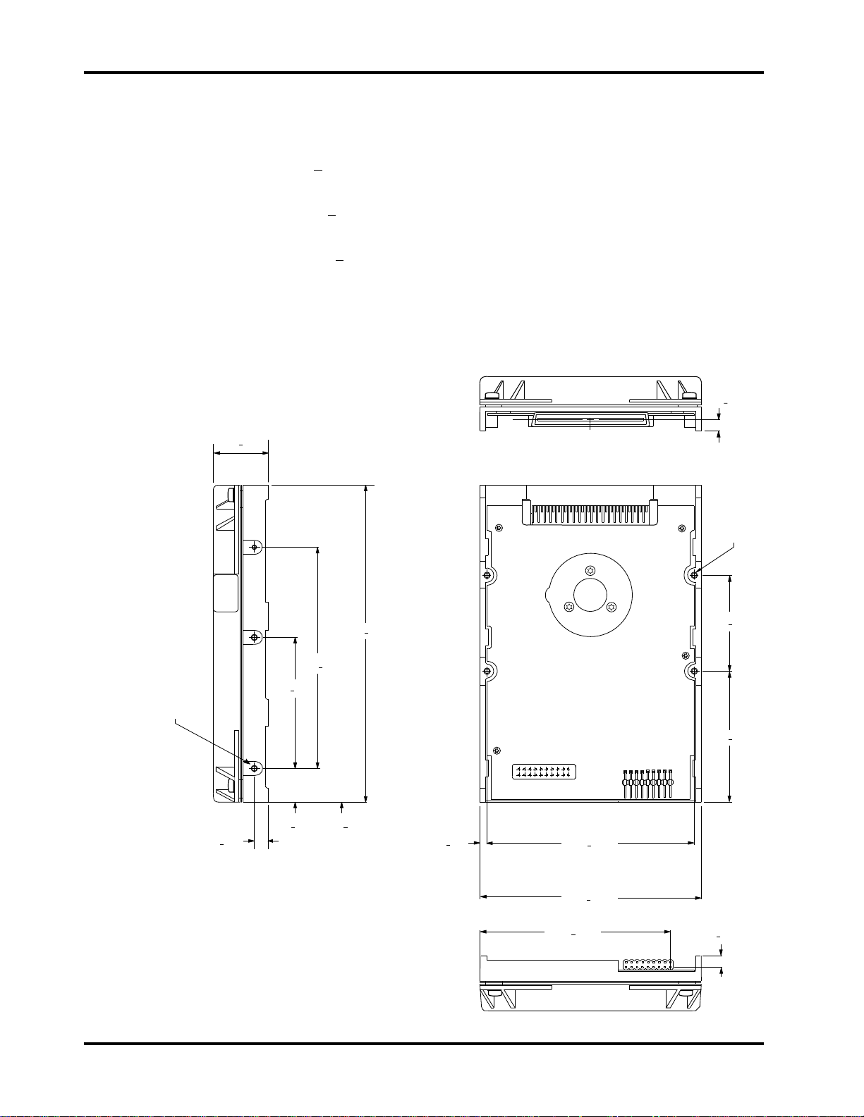
Physical Characteristics - CFP1080E
Height:
• 1.0 inch + .030
Width:
• 4.0 inches + .020
Depth:
• 5.75 inches + .020
Weight:
• 1.3 pounds
Figure 2-1
The Drive’s Physical Dimensions
.153 +0.016
C
1.00 + .030
L
6X 6-32 UNC-2B
.16 MAX. INSERTION
.250 + .010
4.000 + .0035
2.363 + .0035
.630 + .0035
5.75 + .020
.234 + .005
.125 + .005
3.750 + .005
4.00 + .020
3.425 + .015
4X 6-32 UNC-2B
.22 MAX. INSERTION
1.750 + .005
2.375 + .005
.184 + .025
080E_2_1
Page 16 Conner CFP1080E/CFP1080S
Page 25
Specifications Chapter 2
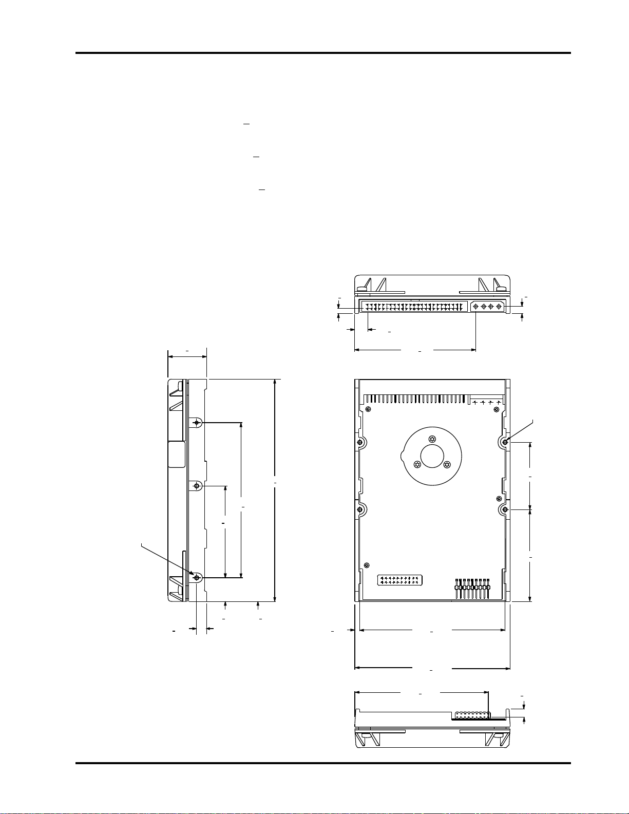
Physical Characteristics - CFP1080S
Height:
• 1.0 inch + .030
Width:
• 4.0 inches + .020
Depth:
• 5.75 inches + .020
Weight:
• 1.3 pounds
Figure 2-2
The Drive’s Physical Dimensions
6X 6-32 UNC-2B
.16 MAX. INSERTION
1.00 + .030
4.000 + .0035
2.363 + .0035
5.75 + .020
.142 + .025
.335 + .015
3.110 + .030
.192 + .022
4X 6-32 UNC-2B
.22 MAX. INSERTION
1.750 + .005
2.375 + .005
.630 + .0035
.250 + .010
080S_2_2
.234 + .005
.125 + .005
3.750 + .005
4.00 + .020
3.425 + .015
.184 + .025
Technical Reference Manual Page 17
Page 26

Chapter 2 Specifications
Page 18 Conner CFP1080E/CFP1080S
Page 27

Drive Operation
3
Drive Functions
This chapter describes certain operational aspects of the drive, including
discussions of:
• drive operational modes
• error correction
• read error recovery
• downloadable microcode
• buffer management
Drive Operational Modes
The drive operates in the following modes:
•• Read/Write Mode occurs when data is read from or written to the disk.
The power consumption specified for this mode is an averaged value
assuming a duty cycle of 35% read and 65% write.
•• Seek Mode occurs when the actuator is in motion 100% of the time.
•• Seek (30%) Mode simulates typical random write/read activity on the drive
where seek has a 30% duty cycle.
•• Idle Mode occurs when the drive is not reading, writing, or seeking. The
motor is up to speed and the Drive Ready condition exists. The actuator is
residing on the last-accessed track.
•• Standby Mode occurs when the motor is stopped and the actuator is
latched in the landing zone. The drive will enter Standby mode after poweron reset if the Disable Spin jumper is installed or the Disable Spin Up bit in
the vendor-specific Mode Page 0 is set. A START STOP UNIT command
with Start = 0 will also place a drive into Standby Mode. The drive will spin
up and go into Idle mode when a START STOP UNIT command is issued
with Start = 1 or on a timed basis by SCSI ID if the Delay Spin Up bit is set
in the vendor-specific Mode Page 0. Refer to the MODE SELECT and
MODE SENSE commands in the Eighth Generation Disk Drive SCSI
Interface Manual for additional details.
•• Spin-Up Mode occurs while the drive's spindle motor is being spun up to
speed after initial power on or after exiting Standby Mode.
Technical Reference Manual Page 19
Page 28

Chapter 3 How the Drive Operates
Error Correction
The drive uses a Reed-Solomon code to perform error detection and correction.
For each 512-byte block, the software error correction polynomial is capable of
correcting:
• one error burst of up to 22 bits in length
• two error bursts each up to 11 bits in length
Single bursts of 11 bits or less are corrected on the fly (OTF) with no
performance degradation. A larger defect up to 22 bits in length or a second
defect of up to 11 bits in length is corrected using firmware within one latency
period, after all retries have been exhausted.
The code has the following error detection capability:
• three error bursts each up to 11 bits in length
• a single burst of up to 51 bits in length
Read Retry Operations
The drive retries data field read operations in the following sequence if it detects
an error which cannot be corrected on-the-fly. The default retry algorithm
repeats up to four times for a total of 64 retry steps or until the data is
recovered.
1. Initial read
2. First retry
3. Read retry with data threshold offset +1
4. Read retry with data threshold offset -1
5. Read retry with data window offset +1
6. Read retry with data window offset -1
7. Write Spash
8. Read retry with data threshold offset +2
9. Read retry with data threshold offset -2
10. Read retry with data window offset +2
11. Read retry with data window offset -2
12. Normal read retry
13. Read retry with servo offset +8%
14. Read retry with servo offset -8%
15. Normal read retry
16. Software (2-burst) EDAC correction attempt
If retries are disabled, the drive retries the operation one time before it reports
an error.
Page 20 Conner CFP1080E/CFP1080S
Page 29

How the Drive Operates Chapter 3
Downloadable Microcode
The SCSI interface code is split into three functional parts which execute from
either ROM or RAM. The SCSI boot code resides in ROM with the disk control
code. It contains the boot-up routines and supports commands such as
INQUIRY, TEST UNIT READY, REQUEST SENSE, START/STOP UNIT, which
do not require media access. The code which supports the rest of the commands
resides on an area of the disk which is reserved to the drive and is not accessible
through the user addressable space. This code is read from the disk and loaded
into static RAM after power is applied and the drive is able to read from the
disk.
Two different types of SCSI control code reside on the disk. The SCSI LookAhead code is the default and is loaded into RAM during the initial power-on
sequence. If a Queue Tag message is received by the drive, the drive will
execute the command and while in Status Phase, will read the SCSI Queuing
code from the disk and load it into the RAM. This operation typically takes
about 100 ms, after which the drive will complete the command by sending the
status. The drive will continue to operate with SCSI Queuing code residing in
RAM until the next Power-On sequence.
Refer to the next section for a discussion of the buffer management implications
for the different types of SCSI control code.
The SCSI control code may be upgraded and saved on the disk via the drive’s
serial port or through SCSI using the WRITE BUFFER command. Refer to the
WRITE BUFFER command in the Eighth Generation Disk Drive SCSI Interface
Manual for a discussion of the procedure.
Technical Reference Manual Page 21
Page 30

Chapter 3 How the Drive Operates
Buffer Management and Command Execution
SCSI Look Ahead Control Code
The SCSI Look Ahead control code executes commands sequentially as they are
received from the initiator(s). Commands from multiple initiators may be
received but will not be reordered.
The drive's data buffer is configured as multiple segments. These segments allow
the drive to cache sequential data from separate areas on the disk. This can
significantly improve performance in any environment in which multiple disk
files are kept open simultaneously and operated upon in some interleaved
fashion.
Buffer operations default on power-up with Read Caching and Write Caching
enabled. The Caching Page RCD bit (Mode Page 8, byte 2, bit 0) when set to one
disables the read cache function. The Caching Page WCE bit (Mode Page 0, byte
2, bit 2) when set to zero disables write cache. In addition, the Caching Page
contains two fields which control the retention priority for reads and writes.
Refer to the Eighth Generation Disk Drive SCSI Interface Manual for additional
details.
When a read command is received by the disk drive, the segment records are
searched to determine if the requested data is cached in a segment (a cache hit).
If there is no cache hit, the next inactive segment is selected and a read from
disk is initiated into that segment. The retention of data already transferred to
the host is controlled by the state of the Demand Read Retention Priority value
in the Caching Page.
Page 22 Conner CFP1080E/CFP1080S
Page 31

How the Drive Operates Chapter 3
The SCSI control firmware always initiates a "read forever" command and the
buffer segment is treated as a circular buffer. Data is retained until the control
firmware determines that it is no longer needed or that performance would be
improved if additional blocks were prefetched. There are three different
situations which would be considered a cache hit on a subsequent read.
• Full Hit: All of the requested data is cached in a buffer segment. The data
may be transferred to the initiator immediately.
• Partial Hit: This is when at least the first block, but not all of the data, is
cached in a buffer segment. Remaining data must be read from the disk,
either by the currently executing disk read process or by a newly instigated
disk read.
• Potential Hit: None of the data is cached; however, the currently executing
disk read is within one revolution of the first block. The current disk read
process is left active and the data is transferred to the initiator after it is
read into the buffer.
Technical Reference Manual Page 23
Page 32

Chapter 3 How the Drive Operates
Write Caching
SCSI Write Caching allows write commands to send status and a command
complete message before the data is written to the disk. This potentially allows
data for multiple sequential write commands to be written to the disk without a
disk revolution intervening between commands. Write caching is enabled by
setting the WCE bit in the Caching Page to one. The WCE bit is only supported
by the Look Ahead code. The WCE bit is ignored by the Queuing code. Write
coalescing allows the same performance advantages.
The drive will send Good status and Command Complete immediately following
the end of the data out phase of a cached write command.
If the drive encounters an error during a cached write operation, the drive will
respond by:
If AWRE (Read-Write Error Recovery Page) is 0: the drive will report a
CHECK CONDITION on the next command and the response to a REQUEST
SENSE will be a deferred error. (Asynchronous event notification is not
supported by this drive.) Refer to the Eighth Generation Disk Drive SCSI
Interface Manual for additional details.
If AWRE is set to 1: the drive will attempt to reassign the block and complete
the operation. If the reassignment fails, the drive will report Check Condition
status on the next command and the response to a Request Sense command will
be a deferred error.
Page 24 Conner CFP1080E/CFP1080S
Page 33

How the Drive Operates Chapter 3
SCSI Queuing Control Code
The drive, operating using the SCSI Queuing control code, can queue up to 32
commands. Reads and writes are re-ordered using minimum access time
prediction. Sequential Read and Write commands are coalesced to maximize
performance.
Command Re-ordering
Commands are re-ordered using a minimum access time prediction algorithm.
Command re-ordering is controlled by Queue Tag Messages (Simple, Head of
Queue or Ordered Queue). Re-ordering of commands may also be restricted
using the Queue Algorithm Modifier bits in the Control Mode Page. Refer to the
Eighth Generation Disk Drive SCSI Interface Manual for additional information
on Messages and Mode Pages.
Buffer Management
The buffer is treated by the SCSI queuing code as multiple segments. Pre-fetch
reads are performed by the drive following a read when there are no commands
in the queue awaiting execution.
Sequential read or write commands are coalesced. For coalesced reads, the data
is transmitted to the initiator as it is read from the disk using a single segment.
On write operations, the drive will transmit the data sequentially into one
segment. The data will be written to the disk as it is available in the buffer
using the single segment and without pause between coalesced commands (if the
SCSI data transfer stays ahead of the disk). This operation provides the
performance of write caching without the exposure of informing the initiator
that the command has completed prior to writing the data to the disk.
Technical Reference Manual Page 25
Page 34

Chapter 3 How the Drive Operates
Page 26 Conner CFP1080E/CFP1080S
Page 35

Installing the Drive
4
Take These Precautions
Installing the Drive
To install the drive, you must:
To protect your equipment from electrostatic damage,
perform the installation at a static-safe workstation. If one is
not available, follow these guidelines:
1. Work in an uncarpeted area.
2. Before removing the equipment from its anti-static bag,
discharge static electricity by touching your computer's
metal chassis (or any other grounded object) while
touching the anti-static bag.
3. Do not touch circuit boards unless instructed to do so.
0170
• set the drive’s jumpers, if desired
• attach a data cable to the drive
• attach power to the drive
• mount the drive
These procedures differ between the various drive models.
Technical Reference Manual Page 27
Page 36

Chapter 4 Installing the Drive
Installing a CFP1080E
The following paragraphs describe the installation procedure for a 16-bit Single
Connector Attachment (SCA) interface, model CFP1080E drive.
Setting the Drive's Jumpers - CFP1080E
There are no jumpers to set on the model CFP1080E drive since all the
necessary control signals are on the SCA connector. This drive is intended for
applications where the drive is configured by asserting the appropriate control
signal on the cable or the backplane.
Setting the SCSI Bus Address - CFP1080E
The SCSI bus ID of the drive is set by grounding the Interface bus signals shown
below in Table 4-1. Refer to Table 5-8 on page 44 for interface connector pin
assignments.
Table 4-1
Setting the SCSI ID
SCSI ID SCSI ID(0) SCSI ID(1) SCSI ID(2)
0
1
2
3
4
5
6
7
Open Open Open
Ground Open Open
Open Ground Open
Ground Ground Open
Open Open Ground
Ground Open Ground
Open Ground Ground
Ground Ground Ground
Page 28 Conner CFP1080E/CFP1080S
Page 37

Installing the Drive Chapter 4
Disabling Spin-Up at Power On - CFP1080E
Spin up upon application of power to the drive can be disabled by grounding the
RMT_START line on the interface. Disabling spin up on application of power
can also be enabled by setting the DSPN bit in MODE SELECT page 00
(Vendor Specific Parameters). The Host must issue a START STOP UNIT
command to cause the drive to spin up. Refer to the Eighth Generation Disk
Drive SCSI Interface Manual for additional information regarding the MODE
SELECT and START STOP UNIT commands.
Table 4-2
Disabling Spin Up at Power On
H
RMT_START
Interface Pin
Ground 0 Spin Disabled
Ground 1 Spin Disabled
Open 0 Spin up on Power On
Open 1 Spin Disabled
Delaying Spin Up at Power On - CFP1080E
Grounding the DLYD_START signal on the interface delays spin up on power-up
by the value of the drive's SCSI ID multiplied by 4 seconds (i.e. SCSI ID 4 will
delay 16 seconds). Delaying spin up on application of power can also be enabled
by setting the SDLY bit in MODE SELECT page 00
Parameters). Refer to Eighth Generation Disk Drive SCSI Interface Manual for
additional information regarding the MODE SELECT command.
Mode Page 0
DSPN bit
Power-On
Behavior
(Vendor Specific
H
Table 4-3
Delaying Spin Up at Power On
DLYD_START
Interface Pin
Mode Page 0
SDLY
bit
Power-On
Behavior
Ground 0 Spin Delayed
Ground 1 Spin Delayed
Open 0 Spin up on Power On
Open 1 Spin Delayed
Host Interface Connection - CFP1080E
The drive may be connected to the host SCSI interface directly through a
backplane SCA connector or through cabling. Both the connector and cabling is
described in Chapter 5.
The design of the SCSI bus interconnect system should meet the following
guidelines, particularly with FAST SCSI-2 systems:
Technical Reference Manual Page 29
Page 38
Chapter 4 Installing the Drive
• Do not route the data signals next to any high frequency or large current
switching signals. Unreliable drive operation can result from improper
signal routing.
• Signal line stubs should not exceed 0.1 meter (4 inches).
• There should be 0.3 meters (12 inches) of transmission line between drives.
• The total length of any signal line should not exceed 6 meters (20 feet) and
may have to be reduced if excessive impedance discontinuities exist on the
bus.
• Maintain a minimum of 0.050 inches (1.27mm) gap between adjacent
signal.runs to control crosstalk between signal lines.
• Signals routed over a ground plane or between ground planes have different
characteristic impedance. Signals with critical timing like REQ, ACK and
Data should be routed similarly.
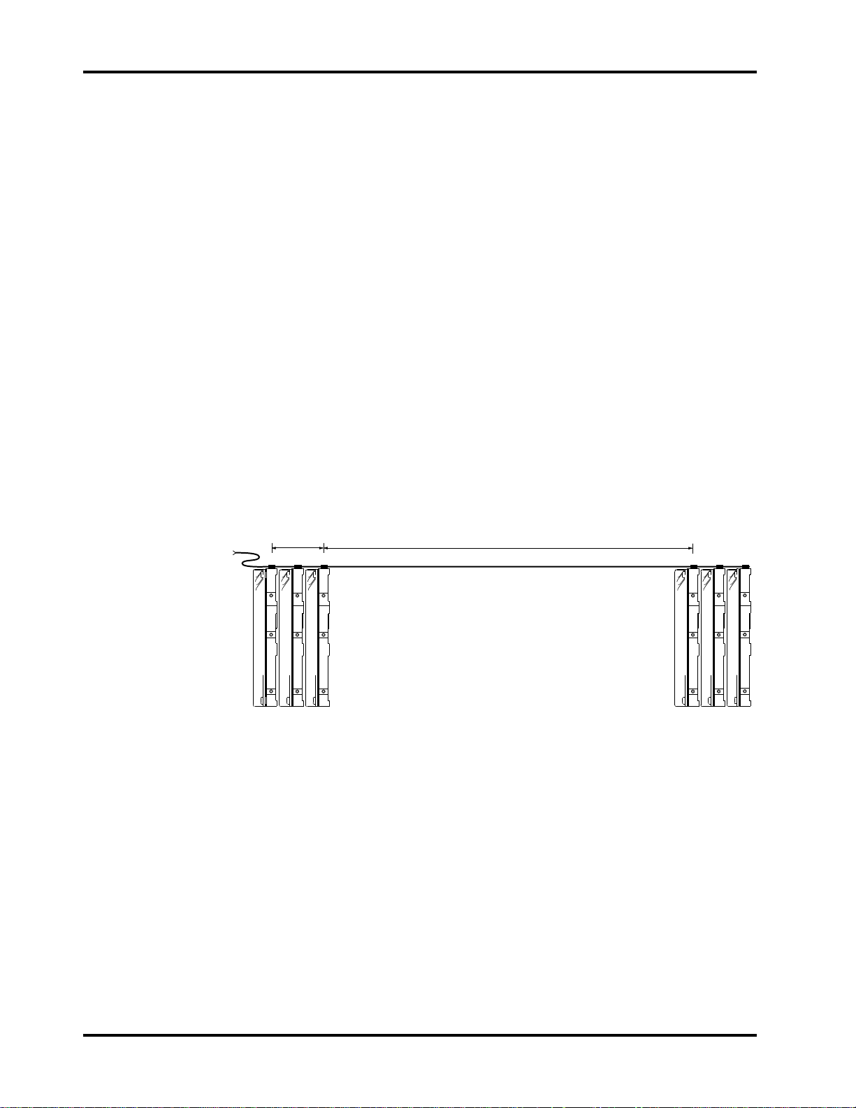
The signal length between devices should either be spaced shorter than the stub
length, which treats a group of devices as a lumped element, or far enough apart
that a transmission line exists (0.3 meters or 12 inches). These signal length
considerations should include the length of signal traces and connectors on the
printed circuit board. The diagram below shows how it is possible to
interconnect six 1-inch height drives over a relatively short length of
interconnect.
3" [0.08m]
maximum
12" [0.3m] minimum
These guidelines apply to both cabled and backplane implementations.
Guidelines specifically for cabled implementations can be found on page 36.
While it is possible to connect SCA drives using a cable, users should be aware
that the mating connector is designed for 0.025 inch (0.63 mm) pitch 30 AWG
wire. There are four +12 volt and three +5 volt line pairs carrying power to the
drive on the SCA so spin up must be staggered to connect two drives on the same
cable. Otherwise, there should only be one drive per cable.
Page 30 Conner CFP1080E/CFP1080S
Page 39

Installing the Drive Chapter 4
Attaching Power to the Drive - CFP1080E
The drive is powered through the SCA interface.
Mounting the Drive - CFP1080E
The drive is designed to be used in applications where the unit may experience
shock and vibrations at greater levels than larger and heavier disk drives will
tolerate.
The design features which allow greater shock tolerance are the use of rugged
heads and media, a dedicated landing zone, closed loop servo positioning and
specially designed motor and actuator assemblies.
Eight side, or four bottom base mounting points are provided to the customer.
The drive is mounted using 6-32 UNC -2B X 0.16 maximum insertion length
screws. Refer to Figure 2-1 in Chapter 2 for the location of the mounting holes.
The system integrator should allow ventilation to the drive to ensure reliable
drive operation over the operating temperature range. The drive may be
mounted in any orientation.
Technical Reference Manual Page 31
Page 40
Chapter 4 Installing the Drive
Installing a CFP1080S
The following paragraphs describe the installation procedure for an 8-bit, 50-pin
SCSI-2 interface, model CFP1080S drive.
Setting the Drive's Jumpers - CFP1080S
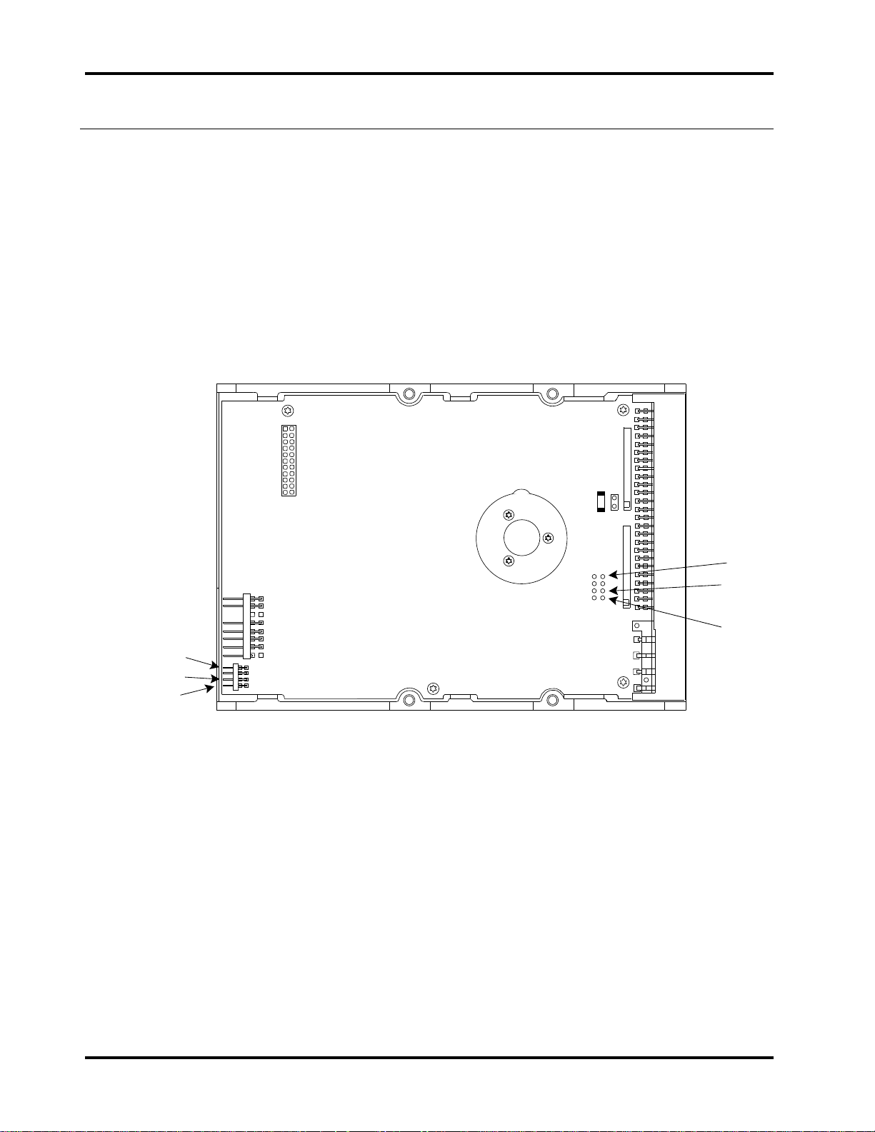
Figure 4-1 shows you where the drive’s jumpers are located.
Figure 4-1
Jumper Locations
Disable
Spin
ID0
ID2
F1
1080S_4_1
J2
ID0
:
ID2
Disable
Spin
J5
J1
J3
SS
LED
:
J6
E1
J4
Page 32 Conner CFP1080E/CFP1080S
Page 41

Installing the Drive Chapter 4
ID1
Out
Out
In
In
Out
Out
In
In
Setting the SCSI Bus Address - CFP1080S
There are three jumpers available for configuration of the SCSI ID: ID0, ID1,
and ID2 located on two different headers. One set is located at J4, behind the
SCSI interface connector. The additional 2mm pin pitch right angle header is
located on the front of the PCBA (opposite the SCSI interface connector).
Either header may be used to configure the SCSI ID of the drive. These headers
may also be used to cable the SCSI ID select to a remote switch. A receptacle
connector Amp P/N 111622-1 or equivalent can be used to connect to this header.
Table 4-4 defines the relationship between the jumpers and the SCSI ID:
Table 4-4
Setting the SCSI ID
SCSI ID ID0
0
1
2
3
4
5
6
7
Note: When controlling the SCSI ID remotely, In = Ground or TTL
Low and Out = Open or TTL High. The signal pins are the odd
numbered pins (1,3,5,7) on both J4 and J6).
Out
In
Out
In
Out
In
Out
In
ID2
Out
Out
Out
Out
In
In
In
In
Technical Reference Manual Page 33
Page 42

Chapter 4 Installing the Drive
Disabling Spin-Up at Power On - CFP1080S
A jumper in the Disable Spin location, disables spin up after power-on for
applications where spin up sequencing is necessary. An optional 2mm pin pitch
right angle header is located on the front of the PCBA (opposite the SCSI
interface connector) can alternatively be used to disable spin up. Disabling spin
up on application of power can also be enabled by setting the DSPN bit in MODE
SELECT page 00
(Vendor Specific Parameters). The Host must issue a START
H
STOP UNIT command with Start=1 to cause the drive to spin up. Refer to the
Eighth Generation Disk Drive SCSI Interface Manual for additional information
regarding the MODE SELECT and START STOP UNIT commands. Refer to
Figure 4-5 for the location of the Disable Spin jumper.
Table 4-5
Disabling Spin Up at Power-On
Disable Spin
Jumper
Mode Page 0
DSPN bit
Power-On
Behavior
In 0 Spin Disabled
In 1 Spin Disabled
Out 0 Spin up on Power On
Out 1 Spin Disabled
Note: In = Ground or TTL Low and Out = Open or TTL High. The
signal is on pin 7 and the low reference is on pin 8 of both J4 and J6.
Disabling SCSI Bus Terminator Power (TERMPWR) - CFP1080S
Power to the on-board terminators is provided by the higher of the voltage
supplied at Pin #26, J2 or the voltage level at the 5 Volt power input to the drive
minus one diode drop. Termination Power to external terminators can be
supplied by the drive through Pin #26, J2. The signal output characteristics are
described in chapter 5. The TERMPWR line can be disconnected from the drive
by removing Jumper E1.
Table 4-6
Disabling SCSI Bus TERMPWR
Jumper E1 Result
In TERMPWR (J2, Pin #26) connected to the drive's
internal termination power.
Out TERMPWR (J2, Pin #26) open circuit.
Page 34 Conner CFP1080E/CFP1080S
Page 43
Installing the Drive Chapter 4
Setting the Bus Termination - CFP1080S
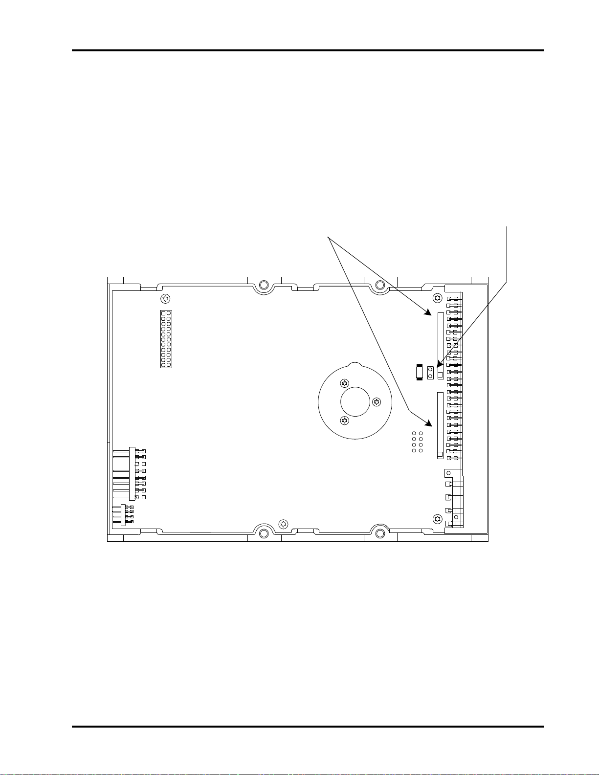
This drive provides on-board Alternative 2 active termination for the SCSI bus.
The termination resistors, which are contained in two Single Inline Packs (SIPs)
should be removed from the drive unless it is a SCSI device at the physical end
of the bus. Figure 4-2 shows the location of the terminator resistors.
Figure 4-2
Terminator Resistor Locations
SCSI Terminators.
Remove in all but the last
Remove to
Disconnect TERMPWR
drive on the SCSI bus
F1
J1
J3
SS
LED
E1
J4
J2
J5
J6
1080S_4_2
Technical Reference Manual Page 35
Page 44
Chapter 4 Installing the Drive
Cabling the Drive - CFP1080S
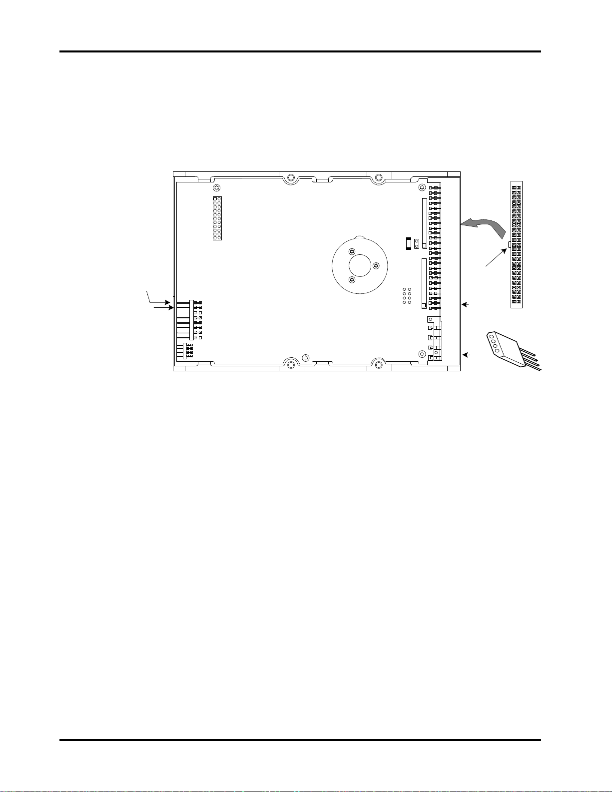
Connect the SCSI interface cable and the spindle synchronization cable (when
needed) as shown in Figure 4-3.
Figure 4-3
Connecting the cabling
Spindle
Synchronization
Connection
LED
Connection
F1
J1
J3
SS
LED
J6
E1
J4
J2
J5
1080S_4_3
50-pin SCSI
Interface
Key
Pin 1 (typically
indicated by a
colored stripe
on the cable
Pin 1
4-pin Power
Connector
SCSI Bus Cable
The cable and mating connector required to connect the drive to the SCSI bus
are described in Chapter 5. In addition, the cable should meet the following
guidelines, particularly with FAST SCSI-2 systems:
• Do not route the data cable next to the drive PCB or any other high
frequency or large current switching signals. Unreliable drive operation can
result from improper cable routing.
• Cable stubs should not exceed 0.1 meter (4 inches).
• There should be 0.3 meters (12 inches) of cable between drives.
• The total cable length should not exceed 6 meters (20 feet) and may have to
be reduced if a mixture of round and flat cable are used.
• Do not tightly bundle excess flat cable against each other since this promotes
cross coupling of signals on the cable. Use spacers to maintain a minimum of
0.050 inches (1.27mm) gap between cable runs.
• Do not clamp the cable tightly against a metal chassis since this will degrade
the signal. Use spacers or a non-flammable insulation material to maintain
a gap between the chassis and the cable.
Spindle Synchronization
The spindle rotation of up to 35 drives may be synchronized together by daisy
chaining pin 1 to pin 1 and pin 2 to pin 2 on connector J3. The spindles are
synchronized using a "floating master" concept, where the drives will
synchronize to the first drive to reach full speed. The synchronization tolerance
is 1%.
Page 36 Conner CFP1080E/CFP1080S
Page 45
Installing the Drive Chapter 4
Attaching Power to the Drive - CFP1080S
The drive has a 4-pin DC power connector, J4 mounted on the PCB. The
recommended mating connector is AMP part number 1-480424-0 utilizing AMP
pins, part number 350078-4 or equivalent.
Connect the DC Power cable to the drive as shown in Figure 4-3.
Attaching a Remote LED - CFP1080S
J3, pin 3
J3, pin 4
Mounting the Drive - CFP1080S
The drive is designed to be used in applications where the unit may experience
shock and vibrations at greater levels than larger and heavier disk drives will
tolerate.
The design features which allow greater shock tolerance are the use of rugged
heads and media, a dedicated landing zone, closed loop servo positioning and
specially designed motor and actuator assemblies.
Eight side, or four bottom base mounting points are provided to the customer.
The drive is mounted using 6-32 UNC -2B X 0.16 maximum insertion length
screws. Refer to Figure 2-3 in Chapter 2 for the location of the mounting holes.
The system integrator should allow ventilation to the drive to ensure reliable
drive operation over the operating temperature range. The drive may be
mounted in any orientation.
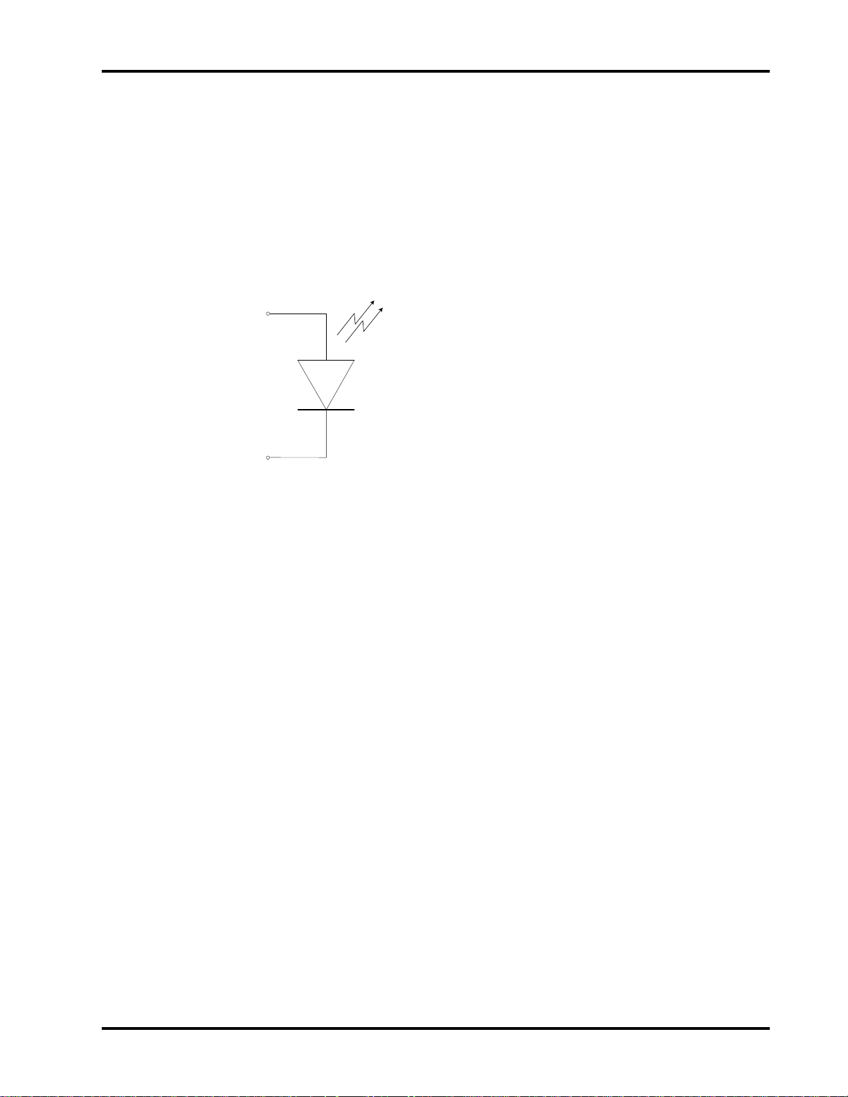
A remote LED can be attached using a 0.1 inch
center, 2-pin connector to pins 3 and 4 of J3. The
anode of the LED should be connected to pin 3
and the cathode to pin 4. The external LED is
connected in parallel to the on board LED and is
powered through a 200 ohm current limiting
resistor to the +5 volt power.
Technical Reference Manual Page 37
Page 46

Chapter 4 Installing the Drive
Page 38 Conner CFP1080E/CFP1080S
Page 47

Interface Physical Characteristics
5
Electrical Description
The paragraphs which follow describe the input and output electrical characteristics
of the drive.
Output Characteristics
The output drivers for Data, Parity, REQ and ACK are optionally active
negation. When they are set for active negation, they have three states:
asserted, negated and high impedance. The remainder of the signals have open
collector (drain) outputs. The drivers maintain a high impedance state during
power-on and power-off cycles. The driven signals have the following output
characteristics when measured at the drive connector:
Table 5-1
Active Negation Driver Output Signal Characteristics
Signal Characteristic Value
Signal Assertion 0.1 VDC to 0.5 VDC at 48 mA
Minimum Driver Output Capability 48 mA (sinking) at 0.5 VDC
Signal Negation 2.0 VDC to 3.24 VDC at 7 mA
3.0 VDC at 20 mA
Table 5-2
Open Collector Driver Output Signal Characteristics
Signal Characteristic Value
Signal Assertion 0.0 VDC to 0.5 VDC at 48 mA
Minimum Driver Output Capability 48 mA (sinking) at 0.5 VDC
Signal Negation 2.5 VDC to 5.25 VDC
Technical Reference Manual Page 39
Page 48

Chapter 5 SCSI Physical Characteristics
Input Characteristics
The characteristics of the input receivers and the requirements for each signal
received by the drive as measured at the drive connector are shown in table 5-3:
Table 5-3
Drive Input Signal Characteristics
Signal Characteristic Value
Signal Assertion 0.0 VDC to 0.8 VDC
Signal Negation 2.0 VDC to 5.25 VDC
Input Load (low level)
Input Load (high level)
-20 µA to 0.0 mA at 0.5 VDC
0.0 mA to 20 µA at 2.7 VDC
Model-Specific SCSI Physical Characteristics
The sections which follow describe, for each of the drive models, those SCSI
characteristics which vary from model to model. These characteristics include:
• Termination
• Cable requirements
• Connector requirements
• Connector Pin assignments
• Interface Timing requirements
Page 40 Conner CFP1080E/CFP1080S
Page 49
SCSI Physical Characteristics Chapter 5
CFP1080E (WIDE, 80-pin Single Connector Attachment [SCA])
External Terminator Power
The interface connector carries both power and ground so a separate TERMPWR
interface line is not provided.
Internal Termination
This version of the drive has no on-board termination so the drive must be
externally terminated. Alternative 2 active termination is recommended.
Cable Requirements
This version of the drive is designed to facilitate interfacing directly to a mating
connector which is on a passive back plane or directly into a motherboard.
The design of the SCSI bus interconnect system should meet the following
guidelines, particularly with FAST SCSI-2 systems:
• Do not route the data signals next to any high frequency or large current
switching signals. Unreliable drive operation can result from improper
signal routing.
• Signal line stubs should not exceed 0.1 meter (4 inches).
• There should be 0.3 meters (12 inches) of transmission line between drives.
• The total length of any signal line should not exceed 6 meters (20 feet) and
may have to be reduced if excessive impedance discontinuities exist on the
bus.
• Maintain a minimum of 0.050 inches (1.27mm) gap between adjacent
signal.runs to control crosstalk between signal lines.
• Signals routed over a ground plane or between ground planes have different
characteristic impedance. Signals with critical timing like REQ, ACK and
Data should be routed similarly.
The signal length between devices should either be spaced shorter than the stub
length, which treats a group of devices as a lumped element, or far enough apart
that a transmission line exists (0.3 meters or 12 inches). These signal length
considerations should include the length of signal traces and connectors on the
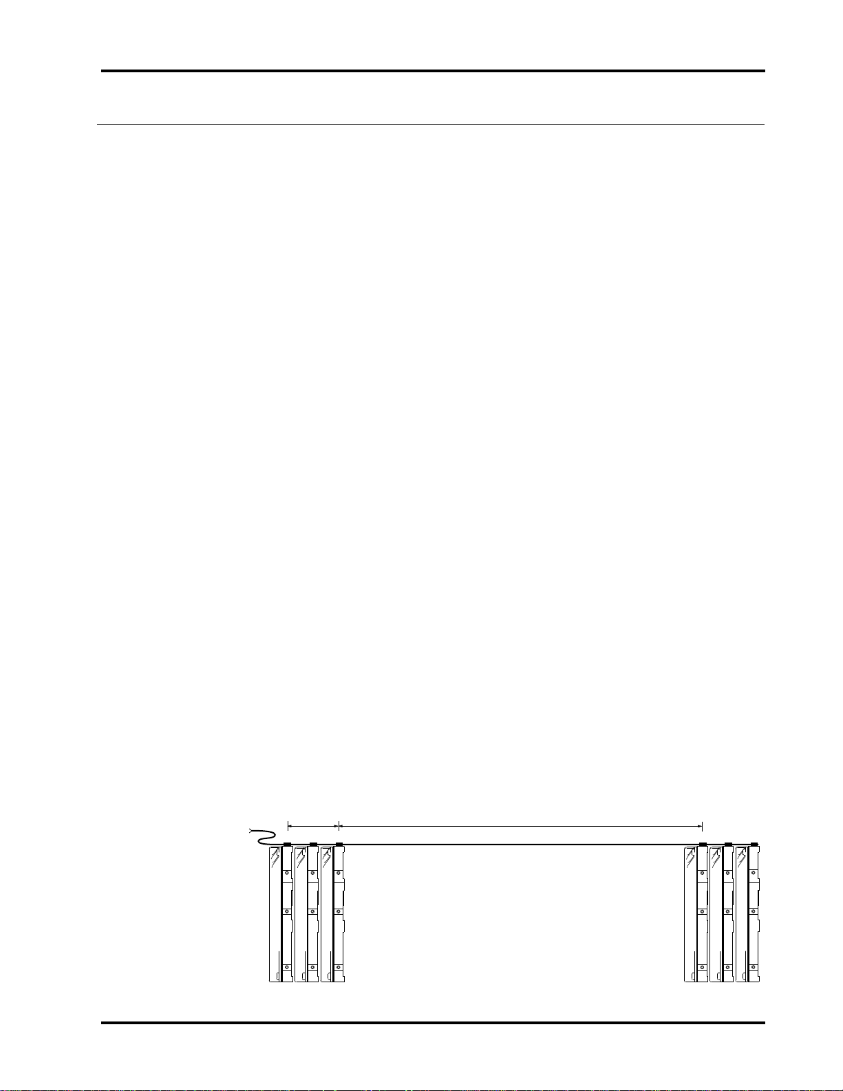
printed circuit board. The diagram below shows how it is possible to
interconnect six 1-inch height drives over a relatively short length of
interconnect.
3" [0.08m]
maximum
Technical Reference Manual Page 41
12" [0.3m] minimum
Page 50

Chapter 5 SCSI Physical Characteristics
Connector Requirements
The drive's connector will mate with a AMP Champ 2-557103-1 vertical
receptacle or the AMP Champ 2-557101-1 right angle receptacle. A mating
connector which is compatible with 0.025 inch (0.63 mm) centerline #30 AWG
solid PVC insulation cabling is AMP Camp 1-557089-3. Refer to figure 2-1 for
the location of the connector on the drive.
Single Connector Attachment (SCA) Signal Definitions
Power
Four +12 volt signals and four +12 volt ground signals provide the +12 volt
power to the drive. The maximum current that can be provided to the drive
through the +12 Volt signal pins is 3 Amperes. The supply current and return
current must be distributed as evenly as possible among the pins. The
maximum current is while the drive motor is starting.
Three +5 volt signals and three +5 volt ground signals provide +5 volt power to
the drive. The +5 volt ground signals are at the same level as the digital logic
ground on the SCSI bus. The maximum current that can be provided to the
drive through the +5 Volt signal pins is 2 Amperes. The supply current and
return current must be distributed as evenly as possible among the pins.
These specifications refer to the connector's characteristics. Refer to Chapter 2
for the drive's power requirements.
Spindle Sync
The spindle rotation of up to 35 drives may be synchronized together by daisy
chaining pin 1 to pin 1 and pin 2 to pin 2 of each drive on connector J3. The
spindles are synchronized using a "floating master" concept, where the drives
will synchronize to the first drive to reach full speed. The synchronization
tolerance is 1%.
Table 5-4
Electrical Characteristics for the Spindle Sync Signal
STATE Current Voltage
High
Low
0 < I
0 < I
< 20 µA
IH
< -48 mA -0.1 V < VIL < 0.4 V
OH
2.5 V < V
< VCC + 0.3 V
IH
LED Out
The LED out signal is driven by the drive when the drive is performing a SCSI
operation. The LED out signal is designed to pull down the cathode of an LED.
The anode is attached to the proper +5 volt supply through an appropriate
current limiting resistor. The LED and the current limiting resistor are external
to the drive.
Page 42 Conner CFP1080E/CFP1080S
Page 51

SCSI Physical Characteristics Chapter 5
Table 5-5
Output Characteristics of the LED Driver Signal
STATE Current Drive Available Output Voltage
Drive LED Off
Drive LED On
0 < I
< 100 µA
OH
< -30 mA 0 < VOL < 0.8 Volts
I
OL
Motor Start Controls
Table 5-6
Electrical Characteristics for RMT_START and DLYD_START
STATE Current Voltage
Open
Ground
0 < I
0 < I
< +100 µA
IH
< -3 mA -0.5 V < VIL < 0.4 V
OH
2.4 V < VIH < VCC + 0.5 V
SCSI ID Selection
Table 5-7
Electrical Characteristics for the SCSI ID Signals SCSI ID (0) - (3)
STATE Current Voltage
Open
Ground
0 < I
0 < I
< +100 µA
IH
< -3 mA -0.5 V < VIL < 0.4 V
OH
2.4 V < VIH < VCC + 0.5 V
Technical Reference Manual Page 43
Page 52
Chapter 5 SCSI Physical Characteristics
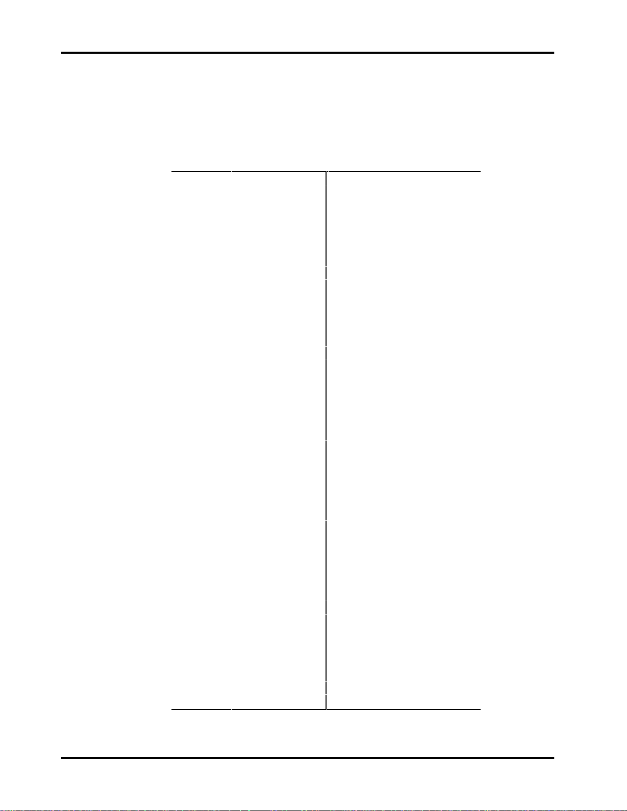
Interface Pin Assignments
The pin assignments for the interface connector are shown below:
Table 5-8
Interface Signal Definitions
Pin Signal Pin Signal
1 +12 Volt 41 +12 Volt Ground
2 +12 Volt 42 +12 Volt Ground
3 +12 Volt 43 +12 Volt Ground
4 +12 Volt 44 +12 Volt Ground
5 Reserved / NC 45 Reserved / NC
6 Reserved / NC 46 Reserved / NC
7 -DB(11) 47 Ground
8 -DB(10) 48 Ground
9 -DB(9) 49 Ground
10 -DB(8) 50 Ground
11 -I/O 51 Ground
12 -REQ 52 Ground
13 -C/D 53 Ground
14 -SEL 54 Ground
15 -MSG 55 Ground
16 -RST 56 Ground
17 -ACK 57 Ground
18 -BSY 58 Ground
19 -ATN 59 Ground
20 -DB(P0) 60 Ground
21 -DB(7) 61 Ground
22 -DB(6) 62 Ground
23 -DB(5) 63 Ground
24 -DB(4) 64 Ground
25 -DB(3) 65 Ground
26 -DB(2) 66 Ground
27 -DB(1) 67 Ground
28 -DB(0) 68 Ground
29 -DB(P1) 69 Ground
30 -DB(15) 70 Ground
31 -DB(14) 71 Ground
32 -DB(13) 72 Ground
33 -DB(12) 73 Ground
34 +5 Volt 74 +5 Volt Ground
35 +5 Volt 75 +5 Volt Ground
36 +5 Volt 76 +5 Volt Ground
37 SYNC 77 LED
38 RMT_START 78 DLYD_START
39 SCSI ID (0) 79 SCSI ID (1)
40 SCSI ID (2) 80 SCSI ID (3)
Notes:
1. The minus sign (-) indicates active low.
2. Pins marked Reserved are not connected.
Page 44 Conner CFP1080E/CFP1080S
Page 53
SCSI Physical Characteristics Chapter 5
Model CFP1080S (Narrow, 50-pin SCSI)
External Terminator Power
Power to the on-board terminators is provided by the higher of the voltage
supplied at Pin #26, J2 or the voltage level at the 5 Volt power input to the drive
minus one diode drop. The diode prevents back flow of current to the drive.
Termination Power to external terminators can be supplied by the drive through
Pin #26, J2. The TERMPWR line can be disconnected from the drive by
removing Jumper E8. Table 5-9 describes the electrical characteristics of the
TERMPWR line when it is used to supply power to an external terminator.
Table 5-10 describes the required electrical characteristics for any external
source of termination power.
Table 5-9
TERMPWR Output Electrical Characteristics
Signal Characteristic Value
Supply voltage 4.06 VDC to 4.56 VDC
Minimum source capability: 800 mA (fused at 1000 mA)
Table 5-10
TERMPWR Input Electrical Characteristics
Internal Termination
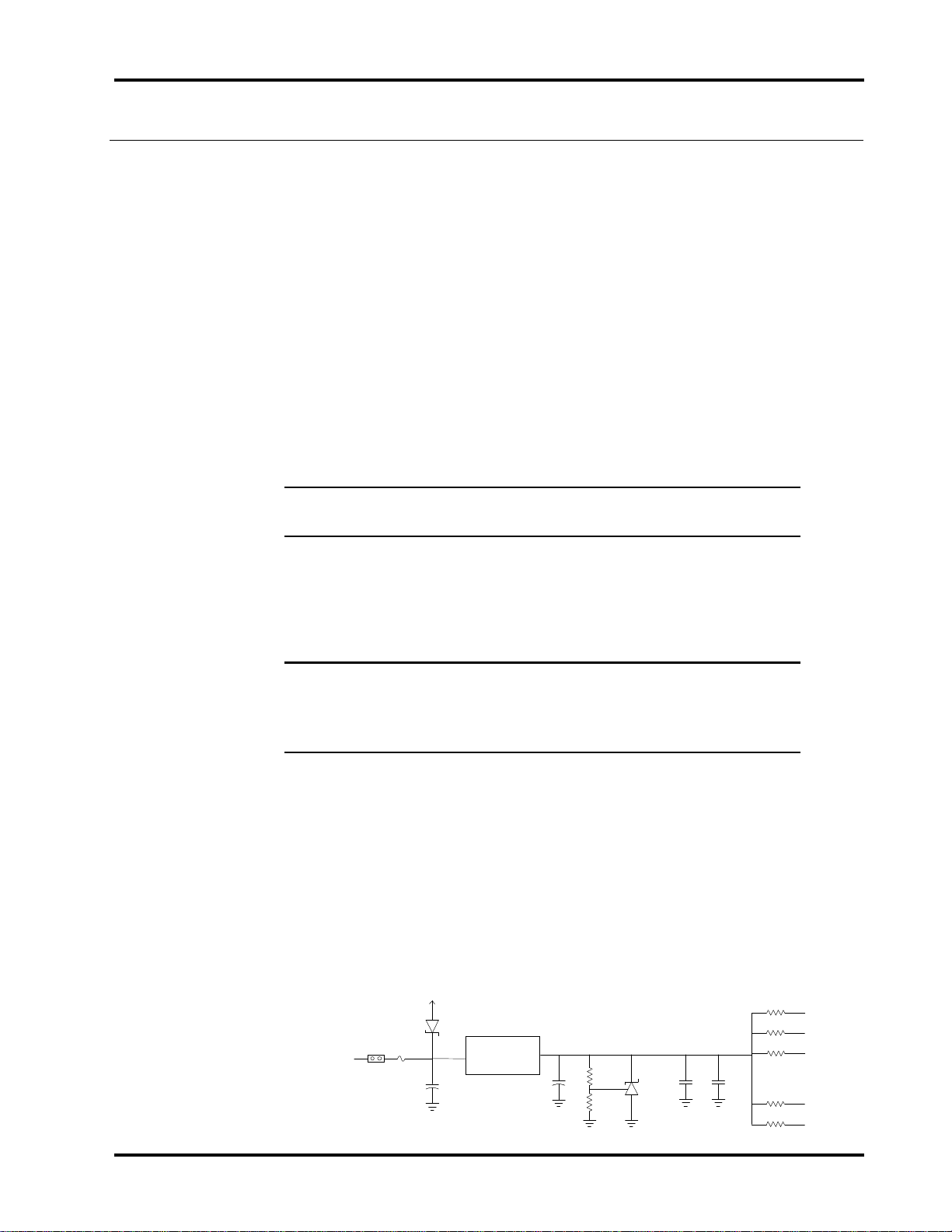
This drive provides on-board Alternative 2 termination for the SCSI bus. The
termination resistors, which are contained in two Single Inline Packs (SIPs)
should be removed from the drive unless it is a SCSI device at a physical end of
the bus. The terminator equivalent circuit is shown below for reference:
Figure 5-1
Terminator Equivalent Circuit
TERMPWR
Signal Characteristic Value
Input voltage 4.00 VDC to 5.25 VDC
Minimum source capability: 1000 mA (fused at 1000 mA)
Sink current: 1.0 mA maximum, excluding power
to the internal terminator.
+5V
F1
E8
Voltage
Regulator
2.5K
10K
110
: :
: :
: :
-DB0
-DB1
-DB2
-REQ
-I/O
Technical Reference Manual Page 45
Page 54

Chapter 5 SCSI Physical Characteristics
Cable Requirements
A 50 conductor cable no more than 6 meters (19.68 feet) cumulative length with
at least 28 AWG wire size and a characteristic impedance of 70 to 100 ohms (84
ohms nominal) is required. In systems which use the fast synchronous transfer
option, the cable should meet the following additional requirements:
Table 5-11
Interface Cable Electrical Characteristics
Specification Value
Signal Attenuation 0.095 dB maximum per meter at 5 Mhz
Pair-to-Pair Propagation Delay Delta 0.20 ns maximum per meter
DC Resistance 0.230 ohms maximum per meter at 20° C
Page 46 Conner CFP1080E/CFP1080S
Page 55
SCSI Physical Characteristics Chapter 5
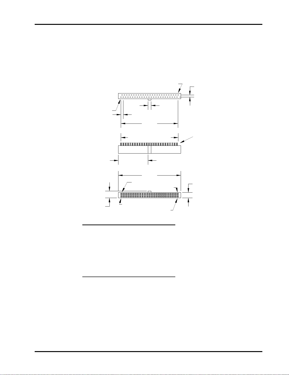
Connector Requirements
The connector on the drive is a 50-position header which consists of 2 rows of 25
male pins on 0.100 inch centers. The mating connector is a SCSI-2 Non-shielded
Alternative 1, A-cable connector which is shown below:
Figure 5-2
A-Cable Connector
Contact 50
C4
Contact 1
C3
C2
See Note 1
C1
Back view
Contacts for even
wires are not shown.
Side view
C5
C6
Socket 1
Socket 49
C8
Socket 2
Socket 50
Dimensions Millimeters Inches
C1 2.540 0.100
C2 60.960 2.400
C3 2.540 0.100
C4 3.302 0.130
C5 32.385 1.275
C6 68.072 2.680
C7 6.096 0.240
C8 7.620 0.300
C7
Front view
Notes:
(1) Fifty contacts on 1.27mm (0.05
inch) staggered spacing =
62.23 mm (2.450 inch) [ref.]
(2) Tolerances +0.127 mm (0.005
inch) noncumulative unless
specified otherwise.
(3) Connector cover and strain
relief are optional
Technical Reference Manual Page 47
Page 56
Chapter 5 SCSI Physical Characteristics
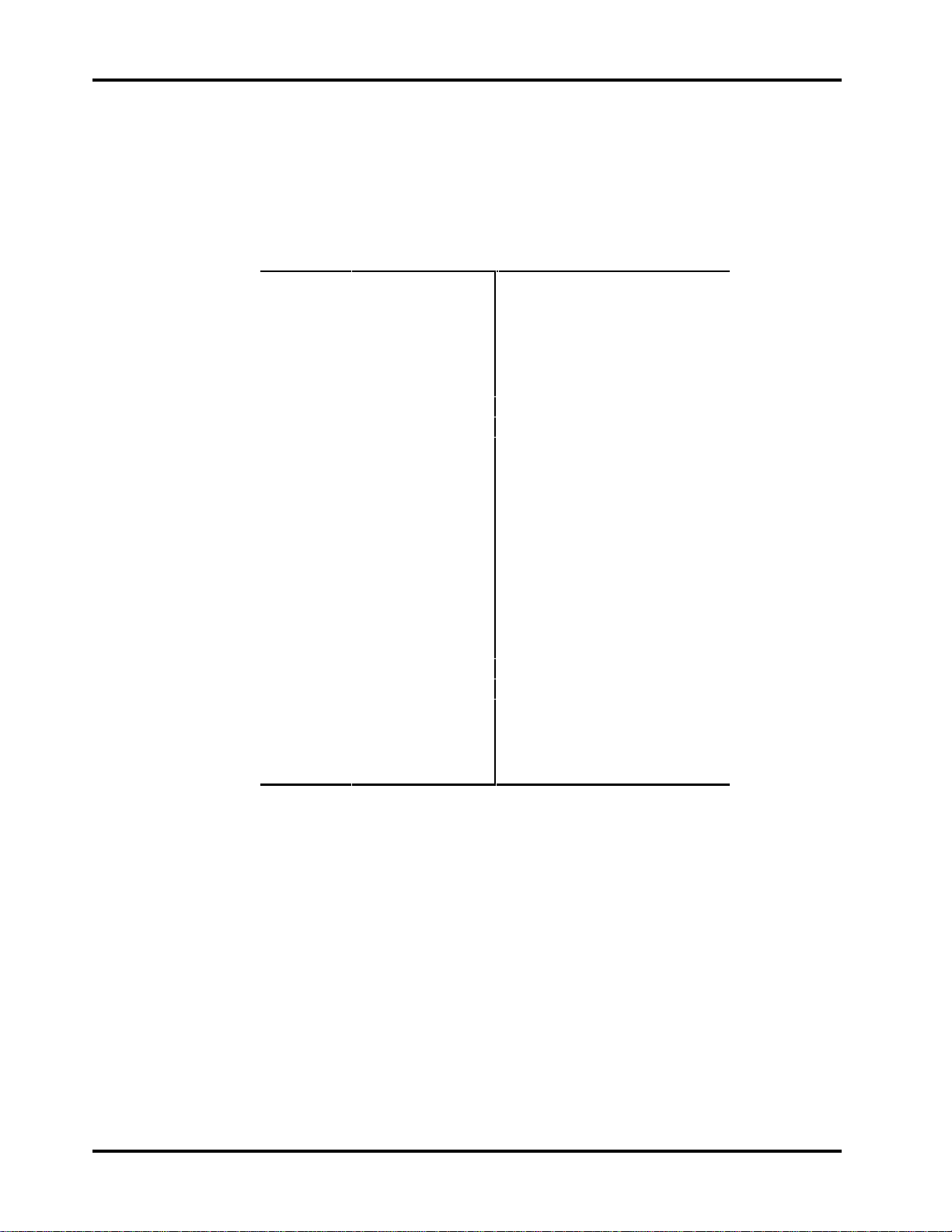
Interface Pin Assignments
The pin assignments for the interface connector are shown below:
Table 5-12
Interface Signal Definitions
Pin Signal Pin Signal
01 GND 02 -DB0
03 GND 04 -DB1
05 GND 06 -DB2
07 GND 08 -DB3
09 GND 10 -DB4
11 GND 12 -DB5
13 GND 14 -DB6
15 GND 16 -DB7
17 GND 18 -DBP
19 GND 20 GND
21 GND 22 GND
23 RESERVED 24 RESERVED
25 OPEN 26 TERMPWR
27 RESERVED 28 RESERVED
29 GND 30 GND
31 GND 32 -ATN
33 GND 34 GND
35 GND 36 -BSY
37 GND 38 -ACK
39 GND 40 -RST
41 GND 42 -MSG
43 GND 44 -SEL
45 GND 46 -C/D
47 GND 48 -REQ
49 GND 50 -I/O
Notes:
1. The minus sign (-) indicates active low.
2. All odd pins except pin 25 must be connected to ground. Pin 25 is left open.
3. Pins marked Reserved are connected to ground.
Page 48 Conner CFP1080E/CFP1080S
Page 57

SCSI Physical Characteristics Chapter 5
y
y
y
y
y
y
g
p
y
y
y
g
Interface Timing Requirements
Unless otherwise noted, the delay-time measurements are calculated from signal
conditions existing at the drive's own SCSI bus connector. Normally these
measurements (except cable skew delay) can be made without considering delays
in the cable.
Table 5-13
SCSI Bus Timing Values
Timing Value *
Timing Description fast slow asynch
Arbitration Dela
Bus Clear Dela
Bus Free Dela
Bus Set Dela
Bus Settle Dela
1
Cable Skew Dela
Data Release Dela
Receive Assertion Period
Receive Hold Time
Receive Ne
Receive Setu
ation Period
Time
Reset Hold Time
Selection Abort Time
Selection Time-out Dela
stem Deskew Dela
S
Transmit Assertion Period
Transmit Hold Time
Transmit Ne
ation Period
Transmit Setup Time
2
2.4 ms 2.4 ms 2.4 ms
800 ns 800 ns 800 ns
800 ns 800 ns 800 ns
1.8 ms 1.8 ms 1.8 ms
400 ns 400 ns 400 ns
4ns 4ns 4ns
400 ns 400 ns 400 ns
22 ns 70 ns n/a
25 ns 25 ns n/a
22 ns 70 ns n/a
15 ns 15 ns n/a
25 ms 25 ms 25 ms
200 ms 200 ms 200 ms
250 ms 250 ms 250 ms
20 ns 45 ns 45 ns
30 ns 80 ns n/a
33 ns 53 ns n/a
30 ns 80 ns n/a
23 ns 23 ns n/a
Notes:
1
This time does not apply at the SCSI connector of the drive.
2
This is a recommended time. It is not mandatory.
Technical Reference Manual Page 49
Page 58

Chapter 5 SCSI Physical Characteristics
Page 50 Conner CFP1080E/CFP1080S
Page 59

SCSI Command Implementation
6
This section contains a list of the SCSI Interface commands implemented in the
drive and the MODE SENSE pages specifically for the drives covered by this
manual. For additional details regarding command descriptions, please refer to
the Eighth Generation Disk Drive SCSI Interface Manual.
SCSI Command Summary
Following is a list of commands that the drive supports:
Format Unit 04
Inquiry 12
Mode Select 15
Mode Sense 1A
Read (6) 08
Read Buffer 3C
Read Capacity 25
Read Defect Data 37
Read Extended (10) 28
Read Long 3E
Reassign Blocks 07
Receive Diagnostics 1C
Release 17
Request Sense 03
Reserve 16
Re-zero Unit 01
Seek (6) 0B
Seek Extended (10) 2B
Send Diagnostic 1D
Start/Stop Unit 1B
Test Unit Ready 00
Verify 2F
Write (6) 0A
Write Extended (10) 2A
Write and Verify 2E
Write Buffer 3B
Write Long 3F
H
H
H
H
H
H
H
H
H
H
H
H
H
H
H
H
H
H
H
H
H
H
H
H
H
H
H
Drive Dependent SCSI Mode Sense Data
The following pages show the drive dependent Mode Sense information for this
drive. The default values are noted in parenthesis (). Parameters not specified
are 00
Technical Reference Manual Page 51
.
H
Page 60
Chapter 6 SCSI Command Implementation
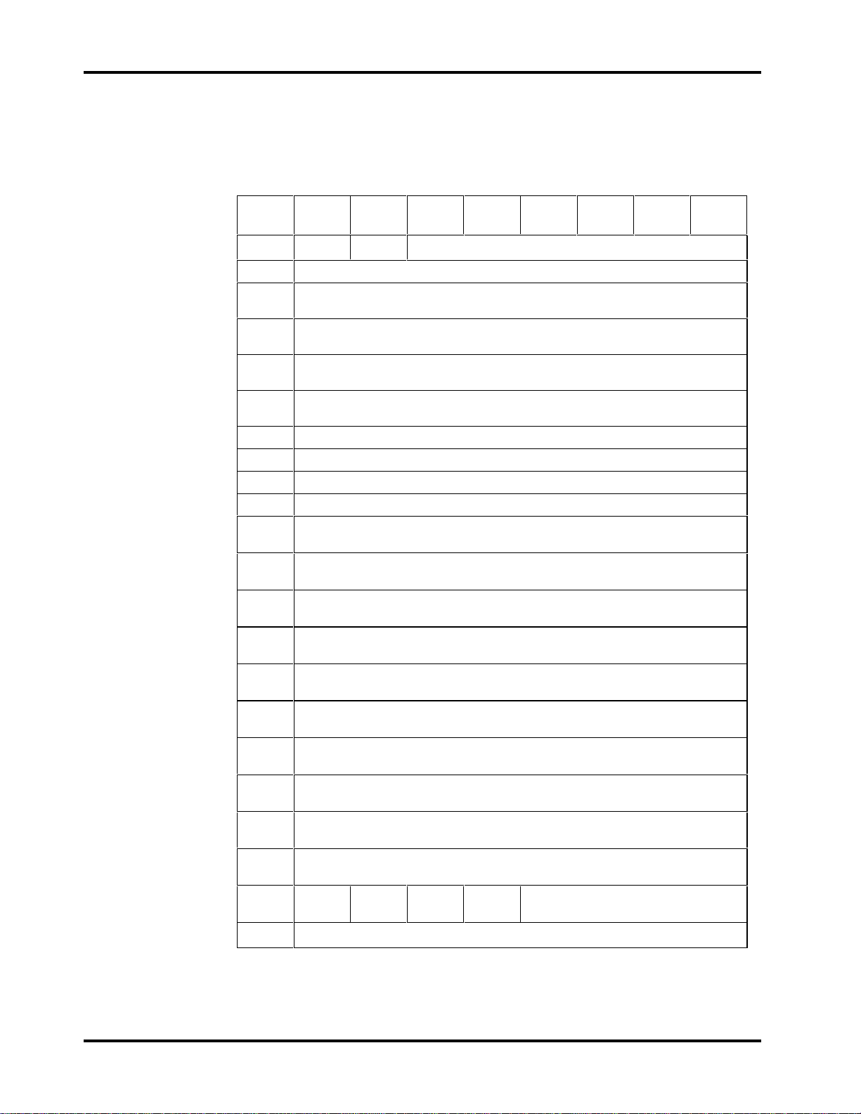
Format Device Page - 03
H
The Format Device Page contains parameters which specify the medium format.
Table 6-1
Format Drive Page Format
Bit
76543210
Byte
0Rsvd Rsvd Page Code = 03
1 Page Length = 16
2
3
4
5
Tracks per Zone (MSB)
(00
H
Tracks per Zone (LSB)
(01
H
Alternate Sectors per Zone (MSB)
(00
H
Alternate Sectors per Zone (LSB)
(01
H
H
)
)
)
)
H
6 Alternate Tracks per Zone (MSB)
7 Alternate Tracks per Zone (LSB)
8 Alternate Tracks per Logical Unit (MSB)
9 Alternate Tracks per Logical Unit (LSB)
10
11
12
13
14
15
16
17
18
19
20
SSEC HSEC
(1)
Sectors per Track (MSB)
(00
)
H
Sectors per Track (LSB)
(78*
)
H
Data Bytes per Physical Sector (MSB)
(02
)
H
Data Bytes per Physical Sector (LSB)
(00
)
H
Interleave (MSB)
(00
)
H
Interleave (LSB)
(01
)
H
Track Skew Factor (MSB)
(00
)
H
Track Skew Factor (LSB)
(0C
)
H
Cylinder Skew Factor (MSB)
(00
)
H
Cylinder Skew Factor (LSB)
(10
)
H
RMB SURF Reserved
21-23 Reserved
* These values are dependent upon the active notch. The values shown are for
the default Active Notch value of 1.
Page 52 Conner CFP1080E/CFP1080S
Page 61

SCSI Command Implementation Chapter 6
Tracks Per Zone: Defines the number of tracks per zone to use in dividing the
capacity of the drive for the purpose of allocating alternate sectors. A value of
zero means that one zone is defined for the entire drive.
Alternate Sectors Per Zone: Defines the number of spare sectors per zone the
drive reserves for defect handling. Not supported. Must be set to zero.
Alternate Tracks Per Logical Unit: Not supported. Must be set to zero.
Sectors Per Track: Defines the number of physical sectors per track. The
number includes the one alternate sector per track the drive allocates. The value
reported for the number of sectors per track is dependent on the active notch
value.
Data Bytes Per Physical Sector: Defines the number of data bytes per
physical sector.
Interleave: Defines the interleave value used by the drive.
Track Skew Factor: Defines the number of physical sectors between the last
logical block of one track, and the first logical block on the next sequential track
of the same cylinder.
Cylinder Skew Factor: Specifies the number of physical sectors between the
last logical block of one cylinder and the first logical block on the next sequential
cylinder.
SSEC (Soft Sector Format): Set to zero to indicate the drive does not support
a soft sector format.
HSEC (Hard Sector Format): Set to one to indicate the drive supports a hard
sector format.
RMB (Removable Media): Set to zero to indicate the drive does not have
removable media.
SURF (Surface Format): The SURF bit is set to zero, meaning the drive
allocates progressive addresses to all logical blocks within a cylinder prior to
allocating addresses on the next cylinder.
Technical Reference Manual Page 53
Page 62
Chapter 6 SCSI Command Implementation
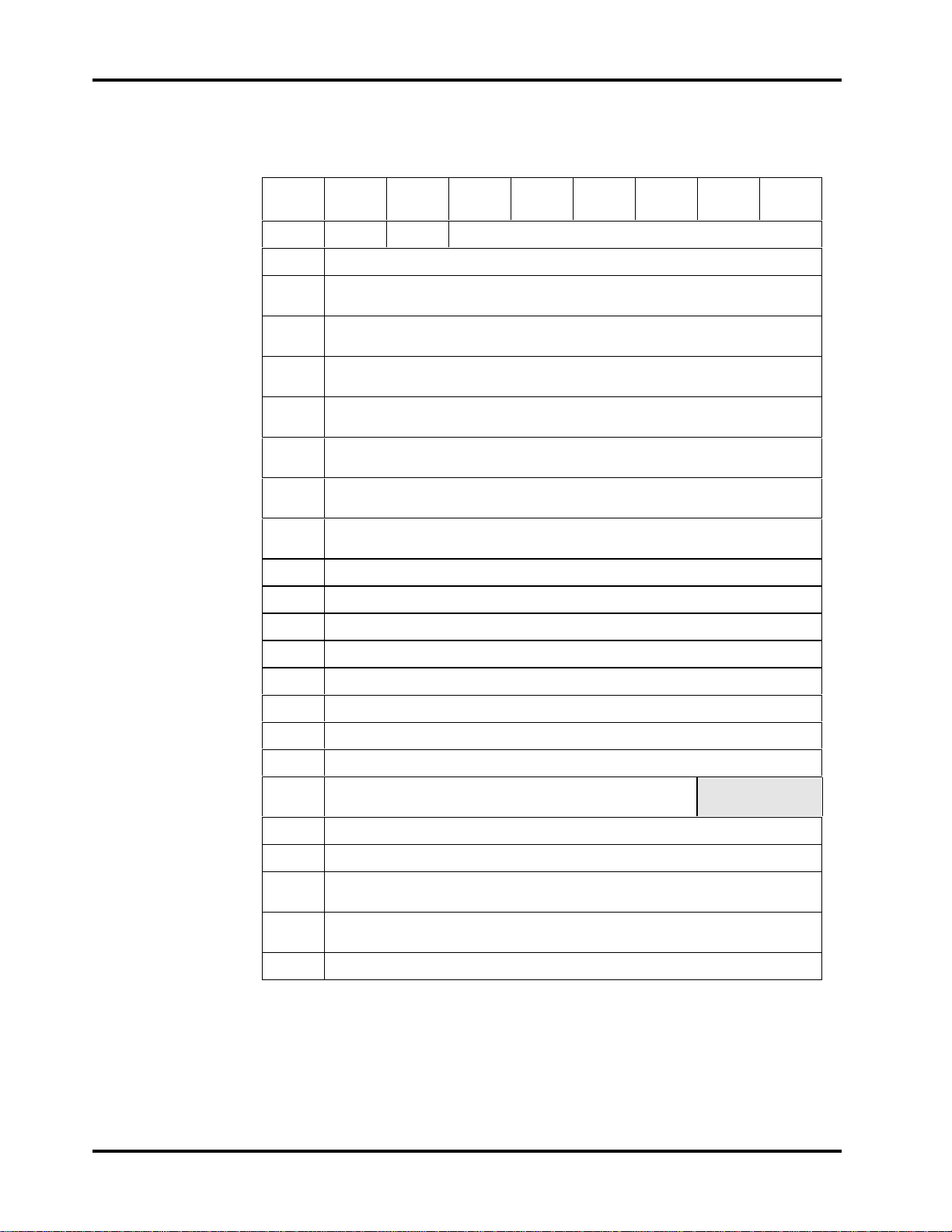
Rigid Disk Geometry Page - 04
H
Table 6-2
Rigid Disk Geometry Page
Bit
76543210
Byte
0
1
Rsvd Rsvd Page Code = 04
Page Length = 16
H
2 Number of Cylinders (MSB)
(00H)
3 Number of Cylinders
(0EH)
4 Number of Cylinders (LSB)
(A4H)
5 Number of Heads
(06H)
6 Starting Cylinder - Write Precompensation (MSB)
(00H)
7 Starting Cylinder - Write Precompensation
(00H)
8 Starting Cylinder - Write Precompensation (LSB)
(00H)
H
9
10
11
12
13
14
15
16
17
Starting Cylinder - Reduced Write Current (MSB)
Starting Cylinder - Reduced Write Current
Starting Cylinder - Reduced Write Current (LSB)
Drive Step Rate (MSB)
Drive Step Rate (LSB)
Landing Zone Cylinder (MSB)
Landing Zone Cylinder
Landing Zone Cylinder (LSB)
Reserved
RPL
(0H)
18
19
20
21
22-23
Rotational Offset
Reserved
Medium Rotation Rate (MSB)
(15
)
H
Medium Rotation Rate (LSB)
(18
)
H
Reserved
Only one copy of this page is maintained. There is only one changeable field,
RPL. All other fields are described in the MODE SENSE Command.
Page 54 Conner CFP1080E/CFP1080S
Page 63

SCSI Command Implementation Chapter 6
RPL (Rotational Position Locking): Enables spindle synchronization.
Setting either bit 0 or 1, or both, causes multiple drives which have their spindle
synchronization (SS) pins daisy chained together to synchronize their spindles.
Notch Page - 0C
H
The Notch Page contains information which pertains to each notch of the drive.
Each section of the drive with a different number of logical blocks per cylinder is
referred to as a notch or zone. Only one copy of this page is maintained. The
only changeable field in this page is Active Notch.
Technical Reference Manual Page 55
Page 64
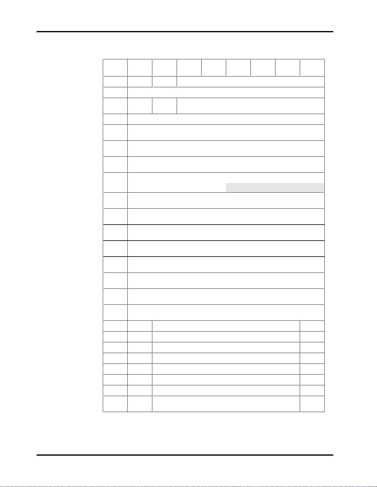
Chapter 6 SCSI Command Implementation
Table 6-3
CFP1080E/CFP1080S - Notch Parameters Page Format
Bit
Byte
76543210
0
1
2
3
4
5
6
7
8
9
10
11
12
13
14
15
16
Rsvd Rsvd Page Code - OC
ND
Page Length = 16
LPN Reserved
H
H
(1)
Reserved
Maximum Number of Notches (MSB)
(00
)
H
Maximum Number of Notches (LSB)
(08
)
H
Active Notch (MSB)
(00
)
H
Active Notch (LSB)
(0H) (1*H)
Starting Boundary (MSB)
(00*
)
H
Starting Boundary
(00*
)
H
Starting Boundary
(08*
)
H
Starting Boundary (LSB)
(00*
)
H
Ending Boundary (MSB)
(00*
)
H
Ending Boundary
(0A*
)
H
Ending Boundary
(F7*
)
H
Ending Boundary (LSB)
(00*
)
H
3F Pages Notched (MSB) 38
17
18
19
20
21
22
23
37 Pages Notched 30
2F Pages Notched 28
27 Pages Notched 20
1F Pages Notched 18
17 Pages Notched 10
0F Pages Notched 08
07 Pages Notched (LSB)
(08
)
H
00
* Varies depending on active notch.
Page 56 Conner CFP1080E/CFP1080S
Page 65

SCSI Command Implementation Chapter 6
ND (Notched Drive): If set to zero, the drive is not notched and all other
parameters in this page are returned as zeros. If set to one, the drive is notched
and this page defines the starting and ending boundaries for each active notch.
This parameter is always set to one.
LPN (Logical or Physical Notch): When set to zero, indicates the notch
boundaries are physical addresses (i.e., cylinder and head). An LPN bit of one is
not supported.
The Maximum Number of Notches field indicates the maximum number of
notches supported by the drive.
The Active Notch field indicates which notch is being referred to by this and
subsequent MODE SELECT and MODE SENSE commands, until changed by a
later MODE SELECT command. Active notches are numbered beginning from
one up to the maximum number of notches.
The Starting Boundary field indicates the beginning of the active notch; the
three most significant bytes represent the cylinder number and the least
significant byte represents the head number.
The Ending Boundary field indicates the ending of the active notch; the three
most significant bytes represent the cylinder and the least significant byte
represents the head number.
The Pages Notched field is a bit map of the MODE SELECT page codes which
indicates the pages containing parameters that are changed for different
notches. The most significant bit of this field corresponds to page code 3F and
the least significant bit represents page code 0. If a bit is a one, the
corresponding MODE SELECT page contains parameters that are changed for
different notches. If a bit is a zero, the corresponding MODE SELECT page
parameters are constant for all notches.
Technical Reference Manual Page 57
 Loading...