

Page 1

CFA810A/CFA1080A
Intelligent Disk Drive
Product Manual
Production Release Per EC 5687
P/N 00550-001
Revision A
May 1994
3081 Zanker Road
San Jose, CA 95134-2128
(408) 456-4500
Page 2

Page 3

FCC Notice
This equipment generates and uses radio frequency energy and, if not installed
and used properly; that is, in strict accordance with the manufacturer's
instructions, may cause interference to radio and television reception. It has
been designed to provide reasonable protection against such interference in a
residential installation. However, there is no guarantee that interference will
not occur in a particular installation. If this equipment does cause interference
to radio or television reception, which can be determined by turning the
equipment on and off, you are encouraged to try to correct the interference by
one or more of the following measures:
• Reorient the receiving antenna.
• Relocate the computer with respect to the receiver.
• Move the computer into a different outlet so that the computer and receiver
are on different branch circuits.
If necessary, you should consult the dealer or an experienced radio/television
technician for additional suggestions. You may find the following booklet
prepared by the Federal Communications Commission helpful:
How to Identify and Resolve Radio-TV Interference Problems
This booklet (Stock No. 004-000-00345-4) is available from the U.S. Government
Printing Office, Washington, DC 20402.
Warning: Changes or modifications made to this equipment which have not
been expressly approved by Conner Peripherals, Inc. may cause radio and
television interference problems that could void the user's authority to operate
the equipment.
Further, this equipment complies with the limits for a Class B digital apparatus
in accordance with Canadian Radio Interference Regulations.
Cet appareil numérique de la classe B est conforme au Règlement sur le
brouillage radioélectrique, C.R.C., ch. 1374.
Conner and the Conner logo are registered trademarks of Conner Peripherals,
Inc. All other trademarks mentioned in this manual are property of their
respective owners.
Copyright 1994, Conner Peripherals, Inc.
All rights reserved.
Document No. 501-065 5/94
Page 4

Important Information About this Manual
All information contained in or disclosed by this document is considered
proprietary by Conner Peripherals, Inc. By accepting this material, the recipient
agrees that this material and the information contained therein are held in
confidence and in trust and will not be used, reproduced in whole or in part, nor
its contents revealed to others, except to meet the purpose for which it was
delivered. It is understood that no right is conveyed to reproduce or translate
any item herein disclosed without express written permission from Conner
Peripherals, Inc.
Conner Peripherals, Inc. provides this manual "as is," without warranty of any
kind, either expressed or implied, including, but not limited to, the implied
warranties of merchantability and fitness for a particular purpose. Conner
Peripherals, Inc. reserves the right to change, without notification, the
specifications contained in this manual.
Conner Peripherals, Inc. assumes no responsibility for the accuracy,
completeness, sufficiency, or usefulness of this manual, nor for any problem that
might arise from the use of the information in this manual.
Page 5

Table of Contents
1. Overview of the Drive 1
2. Specifications 7
Description of the Drives 1
Features of the Drive 1
What the Drive is Composed Of 3
Mechanical Design Features 3
Drive Assembly Housing 4
Head Positioning Mechanism 5
Read/Write Heads and Disks 5
Data and Power Connections 5
Electrical Design Features 5
Integrated Circuit 5
Circuit Board 6
Firmware 6
Specifications In This Chapter 7
Drive Capacity 8
Physical Configuration 8
Performance Characteristics 9
Read/Write Characteristics 10
Reliability 10
Power Requirements 11
Environmental Tolerances 11
Safety Standards 12
Physical Characteristics 13
3. How the Drive Operates 15
Functions of the Drive 15
Drive Operational Modes 15
Error Correction 15
Universal Translate Mode 16
Master/Slave Configuration 16
Supported Master/Slave Modes 17
ISA Original Master/Slave 17
Conner Master/Slave 19
ATA/CAM Master/Slave 20
4. Installing the Drive 21
Take These Precautions 21
Installing the Drive 21
Attaching a Data Cable to the Drive 23
Attaching Power to the Drive 25
Mounting the Drive 26
Technical Reference Manual Page i
Page 6

Table of Contents Filepro CFA810A/CFA1080A
5. Host Interface 27
About the Host Interface 27
Signal Conventions 27
Signal Levels 27
Signal Descriptions 28
ATA/CAM Master/Slave Reset Timing 31
ISA/Conner Master/Slave Reset Timing 33
Host PI0 16-Bit Timing Values 34
Host Demand Mode DMA 16-bit Interface Timing Values 35
6. Register Addresses and Functions 37
Host Address Decoding 37
Addressing the Data 39
Cylinder-Head-Sector (CHS) Mode 39
Logical Block Addressing (LBA) Mode 39
Descriptions of the Registers 40
Data Register 40
Error Register 41
Features Register (formerly Write Precomp Register) 42
Sector Count 42
Sector Number 42
Cylinder Low 43
Cylinder High 43
SDH Register 44
Status Register 45
Alternate Status Register 46
Digital Output Register 47
Drive Address Register 48
Command Register 48
7. Command Set 51
Command Register 51
Conner Specific 52
Get Drive Feature word (00) 53
Read the Drive Switches (02) 54
Power Lock (08) 54
Power Unlock (09) 54
Execute Drive Diagnostic 55
Format Track 56
Marked Bad Sector 56
Assign 56
Identify Drive 58
Initialize Drive Parameters 62
Physical Seek 62
Power Commands 63
Read DMA 64
Read Multiple 65
Read Sector(s) 66
Read Sector Buffer 67
Read Verify Sectors 68
Recalibrate 68
Retry Count 69
Page ii Filepro CFA810A/CFA1080A
Page 7

Filepro CFA810A/CFA1080A Table of Contents
Seek 69
Set Features (Set Look Ahead Read) 70
Set Multiple Mode 71
Translate 71
Write DMA 72
Write Caching 72
Write Multiple 73
Write Caching 73
Write Sector(s) 75
Write Caching 76
Write Sector Buffer 77
8. Error Reporting 79
Error and Status Detection 79
Error and Status Messages 79
Technical Reference Manual Page iii
Page 8

Table of Contents Filepro CFA810A/CFA1080A
Page iv Filepro CFA810A/CFA1080A
Page 9

Overview of the Drive
Capacity (formatted):
810MB
1080MB
Description of the Drives
The Conner Filepro Advantage CFA810A and CFA1080A are high-performance,
low-profile hard disk drives designed to operate with an IBM PC/AT or
equivalent host computer system in translate mode. The drive supports
advanced ATA PIO Mode 3 and DMA Mode 1 data transfer protocols for superior
I/O performance. Logical Block Adressing (LBA) is supported for compatibility
with advanced systems (BIOS) which support greater than 528MB capacity IDE
drives, as well as Cylinder-Head-Sector (CHS) addressing for backward
compatibility. Either a compatible BIOS or a suitable device driver is necessary
to access all of the disk's capacity in a DOS environment.
1
Drive Model: Form Factor:
CFA810A inch high, 3.5 inch
CFA1080A inch high, 3.5 inch
For simplicity, we often refer to the two drives collectively in this manual as "the
drive"
Features of the Drive
The drive provides these features:
• Task File emulation and ATA compatibility allows installation in a wide
range of host systems.
• high-performance rotary voice coil actuator with embedded servoing
eliminate the need for T-cal
• one-of-seven run-length limited code
• high shock resistance
• sealed head/disk assembly
No. of disks/heads:
3 disk/6 heads
4 disk/8 heads
Technical Reference Manual Page 1
• automatic actuator latch against inner stop upon power-down
• microprocessor-controlled diagnostic routines that are automatically
executed at start-up
• 256KB segmentable cache buffer
• Read Look Ahead and selectable Write Caching
• automatic error correction and retries, single burst ECC on the fly
Page 10

Chapter 1 Specifications
• supports ATA Standard PIO Mode 3 and DMA Mode 1
• 512-byte block size
• supports both CHS and LBA addressing
• allows daisy-chaining up to two drives on the AT interface
• Auto-Translate (Universal Translate)
• 4-byte ECC diagnostic check in read/write
The drive supports either of the following Master/Slave protocol standards:
• ATA/CAM (AT Attachment/Common Access Method)
• ISA/Conner (Industry-Standard Architecture)
Page 2 Filepro CFA810A/CFA1080A
Page 11
Specifications Chapter 1
What the Drive is Composed Of
The drive is composed of mechanical, electrical, and firmware elements.
Mechanical Design Features
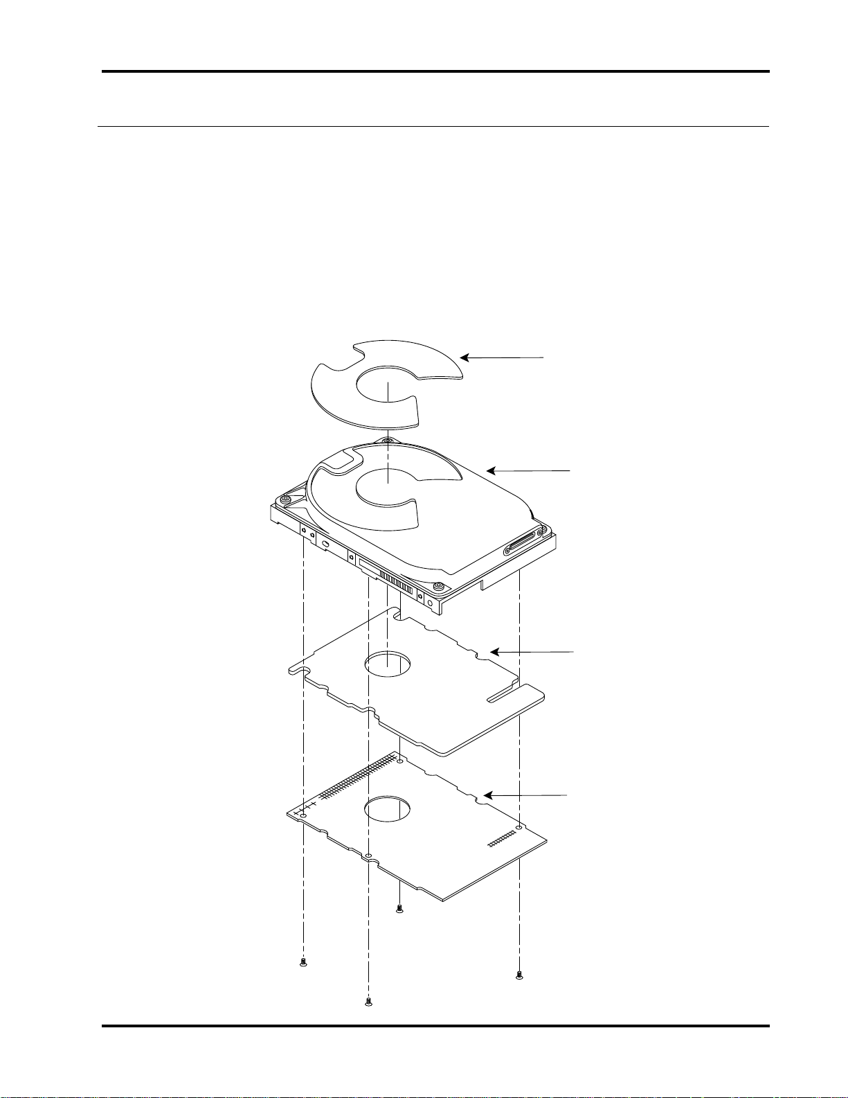
The drive’s hardware includes the components described in the following
sections. Figure 1-1 shows the drive top level assembly, which is a combination
of the drives major mechanical and electrical assemblies.
Figure 1-1
Hard Drive Top Level Assembly
Damper
Head-Disk
Assembly
Printed Circuit
Board Assembly
Shield
Printed
Circuit
Board
Assembly
1080_1_1
Technical Reference Manual Page 3
Page 12
Chapter 1 Specifications
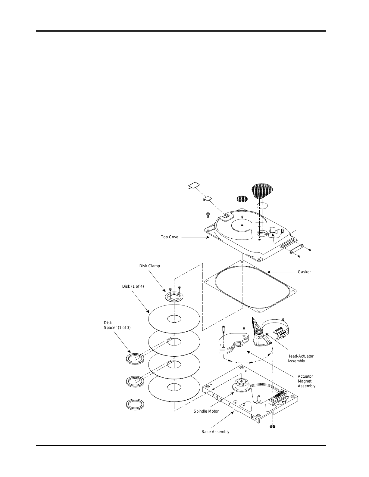
Figure 1-2 shows the details of the drive mechanism, which is called the headdisk assembly.
Drive Assembly Housing
The drive assembly housing consists of a die-cast aluminum base on which is
mounted a die-cast aluminum cover. Both the base and the cover are coated
with a special material designed to seal out contaminants which might degrade
head and media reliability. A gasket seals the joint between the base and cover
to retard the entry of moisture and environmental contaminants from the
assembly.
This assembly, the head-disk assembly, contains an integral 0.3 micron filter,
which maintains a clean environment. Critical drive components are contained
within this contaminant-free environment.
Figure 1-2
Head-Disk Assembly
Disk (1 of 4)
Disk
Spacer (1 of 3)
Filter
Top Cover
Disk Clamp
Gasket
Head-Actuator
Assembly
Actuator
Magnet
Assembly
Spindle Motor
Base Assembly
1080_1_2
Page 4 Filepro CFA810A/CFA1080A
Page 13

Specifications Chapter 1
Drive Motor and Spindle
A brushless DC direct-drive motor assembly is mounted on the drive’s base. The
motor rotates the drive’s spindle at 4500 RPM. The motor/spindle assembly is
dynamically balanced to provide minimal mechanical runout to the disks. A
dynamic brake is used to provide a fast stop to the spindle motor and return the
heads to the landing zone when power is removed.
Head Positioning Mechanism
The read/write heads are supported by a mechanism coupled to a rotary voice
coil actuator.
Read/Write Heads and Disks
Data is recorded on 95mm diameter disks through 3370-type thin film heads.
The CFA810A contains:
• three disks with six data surfaces
• six read/write heads
The CFA1080A contains:
• four disks with eight data surfaces
• eight read/write heads
At power-down, the heads are automatically retracted to the inner diameter of
the disk and are latched and parked on a landing zone that is inside the data
tracks.
Data and Power Connections
The drive has a single 40-pin data connector, as well as an auxiliary connector
which is reserved for factory or evaluation use.
The drive has a standard 4-pin power connector and may optionally have a 3-pin
connector, only one of which should be used at a time.
The drive also has a jumper block located next to the auxiliary connector which
can be set to specify drive operational parameters. For more information on the
drive’s connectors and on setting jumpers, refer to chapters 3 and 4.
Electrical Design Features
Integrated Circuit
A single integrated circuit (IC) is mounted within the sealed hard drive assembly
in close proximity to the read/write heads. The IC provides head selection, read
pre-amplification, and write drive circuitry.
Technical Reference Manual Page 5
Page 14

Chapter 1 Specifications
Circuit Board
The drive’s microprocessor-controlled circuit board provides the remaining
electronic functions, which include:
• read/write circuitry
• rotary actuator control
• interface control
• spin speed control
• auto-park
• power management
Firmware
The drive’s firmware includes a command set which the host uses to control the
drive. The command set allows the host to request the following types of actions:
• report drive status
• seek a specific point on the disk
• read and write data
For more information on the drive’s command set, refer to chapters 6 and 7.
Page 6 Filepro CFA810A/CFA1080A
Page 15

Specifications
2
Specifications In This Chapter
This chapter defines the following specifications for the drive:
• drive capacity
• physical configuration
• performance characteristics
• read/write characteristics
• reliability
• power requirements
• environmental tolerances
• safety standards
• physical characteristics
Technical Reference Manual Page 7
Page 16

Chapter 2 Specifications
CFA1080A:
Sputtered Thin Film
Thin Film
Rotary Voice Coil
4
8
8
Embedded
2801
256KB
3200 tpi
36,352 - 57,856 bytes
512
2,113,984
71 - 113
Universal*
Drive Capacity
Formatted Capacity:
• CFA810A: 810MB
• CFA1080A: 1080MB
* 1MB = 1 x 10⁶ or 1,000,000 bytes
Physical Configuration
Specification CFA810A:
Disk Type
Head Type
Actuator Type
Number of Disks
Data Surfaces
Data Heads
Servo
Tracks per Surface
Buffer Size
Track Density
Formatted Track Capacity
Bytes per Block
Blocks per Drive
Sectors per Track (User)
Translate
* Refer to chapter 3 for a definition of Universal Translate Mode
Sputtered Thin Film
Thin Film
Rotary Voice Coil
3
6
6
Embedded
2801
256KB
3200 tpi
36,352 - 57,856 bytes
512
1,585,488
71 - 113
Universal*
Page 8 Filepro CFA810A/CFA1080A
Page 17

Specifications Chapter 2
Performance Characteristics
Seek Times (typical)* :
• Track to track: 3.0 ms
• Average: 10.5 ms read, 11.5 ms write **
• Maximum: 20 ms
• The timing is measured through the interface with the drive operating at nominal DC input
voltage and nominal operating temperature. The timing also assumes that:
• BIOS and PC system hardware dependency have been subtracted from timing
measurements
• the drive is operated using its native drive parameters
• the controller overhead is the time it takes to assert +HOST IRQ after the host writes the
command register with a READ instruction, for the case where the data already resides
in the buffer
** The average seek time is determined by averaging the seek time for a minimum of 1000 seeks
of random length over the surface of the disk.
Average Latency:
• 6.67 ms
Rotation Speed:
• 4500 RPM (+ 0.1%)
Average Controller Overhead:
• <500 µsec
Start Time at Power-Up: *
• 0 RPM to 4500 RPM
- Typical: 7 seconds
- Maximum: 12 seconds
• 0 RPM to Ready
- Typical: 12 seconds
- Maximum: 20 seconds
* These numbers assume spin recovery is not invoked. If spin recovery is invoked, the
maximum could be 40 seconds. Briefly removing power can lead to spin recovery being
invoked.
Stop Time at Power-Down:
• Typical: 15 seconds
• Maximum: 20 seconds
Interleave:
• 1:1
Technical Reference Manual Page 9
Page 18

Chapter 2 Specifications
Read/Write Characteristics
Interface:
• Task File
Recording Method:
• 1 of 7 RLL code
Recording Density (ID):
• 65,000 bits per inch
Flux Density (ID):
• 48,340 flux reversals per inch
Data Transfer Rate:
• To/From Media: 3.4 - 5.76 MB/second
• To/From Host: 11.1 MB/second burst, 8.3 MB/second sustained
Reliability
Data Reliability:
• < 1 non-recoverable error in 10
Component Design Life:
• 5 years
Start/Stop Cycles:
• 20,000 minimum
Mean Time Between Failures:
• 300,000 power-on hours
Mean Time to Repair:
• 10 minutes typical
Preventive Maintenance:
• none
14
bits read
Page 10 Filepro CFA810A/CFA1080A
Page 19

Specifications Chapter 2
Power Requirements
+5 Volts
Mode: *
Read/Write
Seek (100%)
Seek (30%)
Idle
Standby
Sleep
Spin-Up
* Refer to chapter 3 for the definitions of the modes. Spin-Up Mode current draw is for 7 seconds,
maximum. Typical conditions are both voltages at nominal value, room temperature (25° C)
ambient to the drive. Maximum power is when the supply voltage is at the worse case condition.
(typical):
640 mA 190 mA 5.5 W 6.1 W
620 mA 490 mA 9.0 W 10.1 W
440 mA 230 mA 5.0 W 5.4 W
420 mA 180 mA 4.3 W 4.7 W
380 mA 80 mA 2.9 W 3.3 W
260 mA 80 mA 2.3 W 2.5 W
720 mA 1600 mA N/A N/A
+12 Volts
(typical):
Watts
(typical):
Watts
(maximum):
Minimum/Maximum Voltage:
• +5V: +5%
• +12V: +10%
Maximum Peak-to-Peak Noise Allowed
(DC to 1 MHz, with equivalent resistive load):
• +5V: 2%
• +12V: 1%
Environmental Tolerances
Temperature:
• Operating: 5° to 55° C
• Non-operating: -40° to 60° C
• Thermal Gradient: 20
Relative Humidity (non-condensing):
• Operating: 5 to 95%
• Non-operating: 5 to 95%
• Wet Bulb: 29
Altitude (relative to sea level):
• Operating: -200 to 15,000 feet
• Non-operating: 40,000 feet (maximum)
• Altitude Gradient: 1,000 feet/minute
Shock (half-sine pulse, 11 ms duration):
• Operating: 5G without non-recoverable errors
• Non-operating: 75G without non-recoverable errors
o
C per hour maximum
o
C
Technical Reference Manual Page 11
Page 20

Chapter 2 Specifications
Vibration (swept-sine, one octave per minute):
• Operating
- 5 - 32 Hz: 0.01 inch displacement; double amplitude
- 32 - 400 Hz: 0.5G without non-recoverable errors
• Non-operating
- 5 - 28 Hz: 0.10 inch displacement; double amplitude
- 28 - 400 Hz: 4G peak
Magnetic Field:
• The disk drive will meet its specified performance while operating in the
presence of an externally-produced magnetic field under the following
conditions:
Field Frequency Intensity
Acoustic Noise:
• The sound pressure level will not exceed 38 dBA in Idle Mode at a distance
Safety Standards
The drive is designed to comply with relevant product safety standards,
including:
• UL 478, 5th edition, Standard for Safety of Information Processing and
• UL 1950, Standard for Safety of Information Technology Equipment
• CSA 22.2 #220, Information Processing and Business Equipment
• CSA 22.2 #950, Safety of Information Technology Equipment
DC
to 700 Khz
700 Khz to 1.5 Mhz
of 1 meter from the drive. The sound power level measured based on ISO
7779 will not exceed 4.3 Bel in Idle Mode.
Business Equipment
6 gauss
7 milligauss
3 milligauss
• IEC 380, Safety of Electrically Energized Office Machines
• IEC 950, Safety of information Technology Equipment Including Electrical
Business Equipment
• VDE 0805, VDE 0805 TIEL 100, and VDE 0806
• Complies with FCC Class B, Part 15, Subpart J
Page 12 Filepro CFA810A/CFA1080A
Page 21
Specifications Chapter 2
Physical Characteristics
Height:
• 1.0 inch + .030
Width:
• 4.0 inches + .020
Depth:
• 5.75 inches + .020
Weight:
• 1.30 pounds
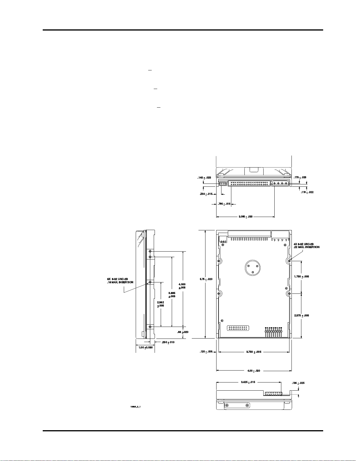
Figure 2-1
The Drive’s Physical Dimensions
8X 6-32 UNC-2B
.16 MAX. INSERTION
1.00 +0.030
2.362
+.005
3.695
+.005
.250 + 010
4.000
+.005
.63 +.020
.145 + .025
.254 + .015
5.75 + .020
.125 + .005
.795 + .015
3.095 + .030
3.750 + .005
.178 + .025
.119 + .022
4X 6-32 UNC-2B
.22 MAX. INSERTION
1.750 + .005
2.375 + .005
4.00 + .020
1080A_2_1
3.425 + .015
+
+
.184 + .025
Technical Reference Manual Page 13
Page 22

Chapter 2 Specifications
Page 14 Filepro CFA810A/CFA1080A
Page 23

How the Drive Operates
3
Functions of the Drive
This chapter describes certain operational aspects of the drive, including
discussions of:
• drive operational modes
• error correction
• Universal Translate Mode
• master/slave configurations
Drive Operational Modes
The drive operates in the following modes:
• Read/Write Mode occurs when data is read from or written to the disk.
• Seek Mode (100%) occurs when the actuator is in motion.
• Seek Mode (30%) is composed of 1/3 stroke seeks with a 30% duty cycle.
Error Correction
• Idle Mode occurs when the drive is not reading, writing, or seeking. The
motor is up to speed and the Drive Ready condition exists. The actuator is
residing on the last-accessed track.
• Standby Mode occurs when the motor is stopped and the actuator is
parked. Standby Mode occurs after a programmable time-out since the last
host access occurs. The drive will leave Standby Mode upon receipt of a
command which requires disk access, or upon receipt of a spin-up command.
• Sleep Mode occurs when all electronics are disabled. The host is required
to issue a Reset command to exit the Sleep Mode.
• Spin-Up Mode occurs while the drive is spun up to speed after being
powered on or after exiting Standby or Sleep Mode.
The drive uses a Reed-Solomon code to perform error detection and correction.
For each 512-byte block, the software error correction polynomial is capable of
correcting:
• one error burst up to 22 bits
• two error bursts up to 11 bits each
Single bursts of 11 bits or less are corrected on the fly (OTF) with no
performance degradation.
Technical Reference Manual Page 15
Page 24

Chapter 3 How the Drive Operates
No. of
Sectors:
63
63
Universal Translate Mode
Conner has established a Universal Translate Mode which enables you to
configure the drive in an AT environment to any cylinder, head, and sector
configuration desired. The translate configuration is limited by the maximum
capacity of the drive and host system parameters. Upon initial power-up of the
drive, it will default to the configuration shown below:
No. of
Drive:
Cylinders:
No. of Heads
CFA810A
CFA1080A
After the drive is ready, the host system may issue an Init Drive Parms
command (command code 91
heads and number of sectors per track). The drive will then:
• calculate the total number of available logical tracks based upon the entered
sector and head values
• save the drive parameters in non-volatile memory for subsequent drive
operations
☞ Note: BIOS in older systems may be limited to a maximum of 1024 cylinders. It may be
necessary to manually enter 1024 cylinders into the User Defined parameter list in this
case. Device drivers are available to overcome this limitation and the instructions which
accompany the driver should be followed for installation.
Master/Slave Configuration
When two drives are daisy-chained on the host interface, one must be designated
as the master drive (C: drive) and one as the slave drive (D: drive).
Commands from the host are written in parallel to both drives.
1572 16
2097 16
hex) to alter the translate configuration (number of
When the C/D jumper on the drive is closed, the drive will assume the role of a
master. When C/D is open, the drive will act as a slave. In single-drive
configurations, C/D must remain in the closed (master) position. For more
information on setting the C/D jumper, refer to chapter 4.
For each command sent from the host, the DRV bit in the drive/head register
selects the master or the slave drive. When the DRV bit is reset (0), the master
drive is selected, and when the DRV bit is set (1), the slave drive is selected.
Once the drives receive the command, only the drive with jumper C/D set to the
appropriate position will execute the command. For example, if the DRV bit is
set, only the slave drive (jumper C/D open) will execute the command.
☞☞ Note: If the command is a diagnostic command, both drives will execute the command
and the slave will report its status to the master via the Host PDIAG signal.
Page 16 Filepro CFA810A/CFA1080A
Page 25

How the Drive Operates Chapter 3
Throughout this manual, drive selection always refers to the state of the DRV
bit and the position of the C/D jumper.
The drive supports two master/slave modes via the A/C jumper. When A/C is
closed, ATA/CAM master/slave mode is selected. When A/C is open, Conner
master/slave mode is selected. For more information on setting the A/C jumper,
refer to chapter 4.
Supported Master/Slave Modes
There are three different master/slave methods that Conner supports.
• ISA Original
• Conner
• ATA/CAM
Of these three methods, the drive supports all except ISA/Original mode, with
which it is compatible.
☞☞ Note: The ATA/CAM master/slave method is not compatible with the other two methods.
The Conner mode is backward-compatible to the ISA Original mode, but is not
compatible with the other.
These three methods are explained in the following sections. For signals
followed by a ‘~’, activate means go low and deactivate means go high.
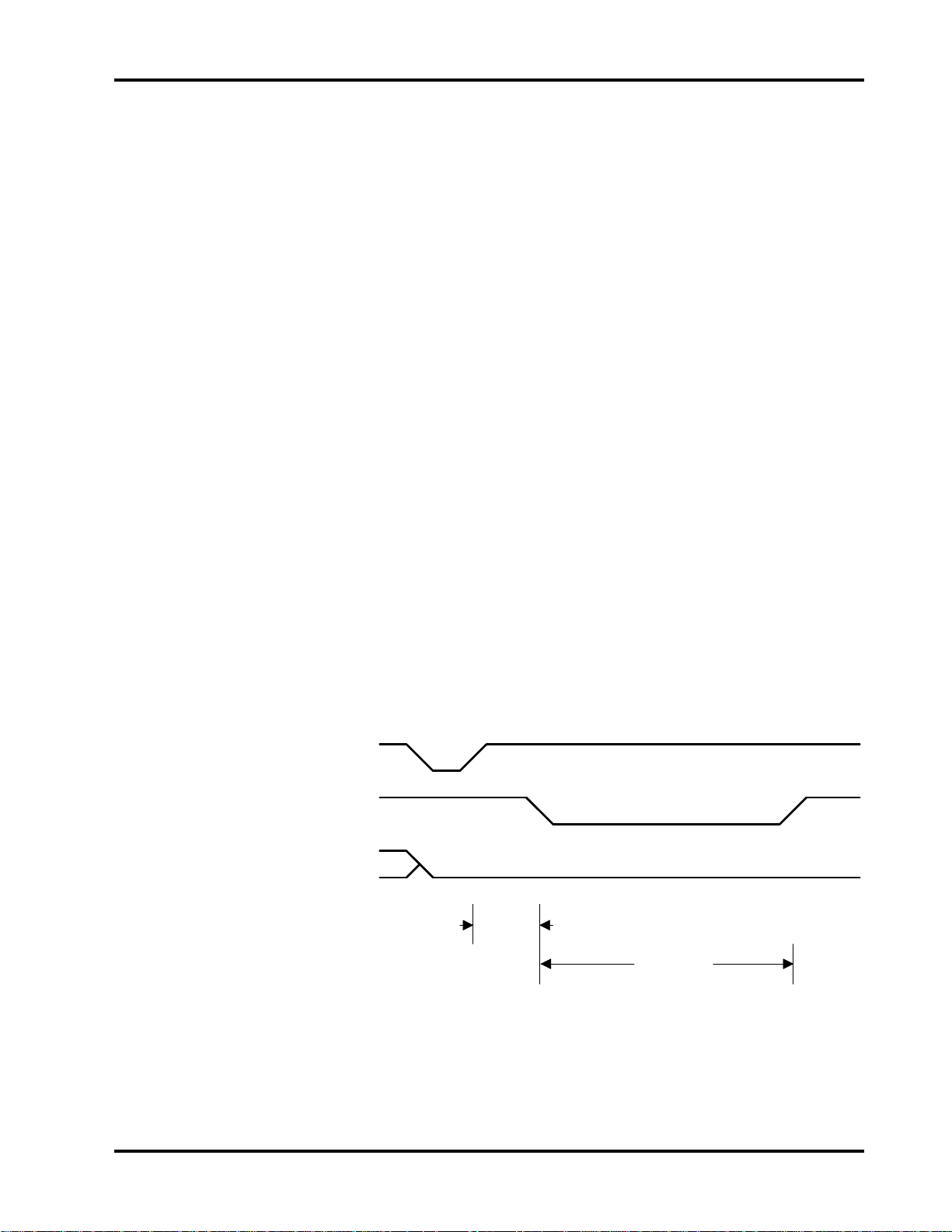
ISA Original Master/Slave
The signals used for master/slave operation and determination are Host DASP~
and Host PDIAG~.
Host DASP~ can be used to:
• drive an activity LED
• indicate that the slave drive is present to the master
The Host PDIAG~ is used to indicate that the slave has passed diagnostics both
at power-on reset (POR) and when the diagnostic command is issued.
At power-on time, the slave drive activates Host PDIAG~ and Host DASP~.
Host PDIAG~ remains activated from POR until a diagnostic command is issued
by the host. Once a diagnostic command is issued by the host, the slave
deactivates Host PDIAG~ until either:
• the slave successfully completes the diagnostic command
• the host issues a reset
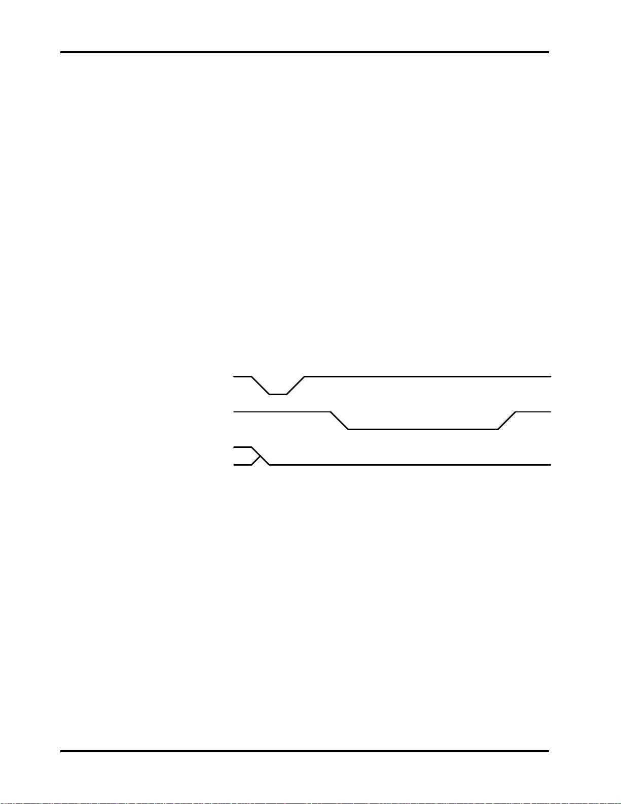
There are no real timing constraints on Host PDIAG~ and Host DASP~. At
POR, they are both activated within a second or two. When the diagnostic
command is issued by the host, the slave inactivates Host PDIAG~ within 100-
Technical Reference Manual Page 17
Page 26
Chapter 3 How the Drive Operates
200 microseconds and is required to reactivate it within 5 seconds (the only
timing constraint) if it successfully completes the command.
This scheme works fairly well except for two problems:
• There is no way to tell when the slave becomes ready. If the slave becomes
ready much later than the master, the slave will miss any commands that
are issued before it goes not busy because the host only polls the master to
see if the “controller” is ready.
• In a two-drive configuration, the Host DASP~ line is not available to drive a
drive activity indicator.
In this mode of master/slave, master/slave re-configures with either a hardware
or software reset. A hardware reset is either a POR or host reset.
This version of master/slave is present on generations 1, 2 and 3 of Conner
drives.
Figure 3-1
ISA Original Master/Slave Timings
Any Reset
Host PDIAG~
Host DASP~
Page 18 Filepro CFA810A/CFA1080A
Page 27
How the Drive Operates Chapter 3
Conner Master/Slave
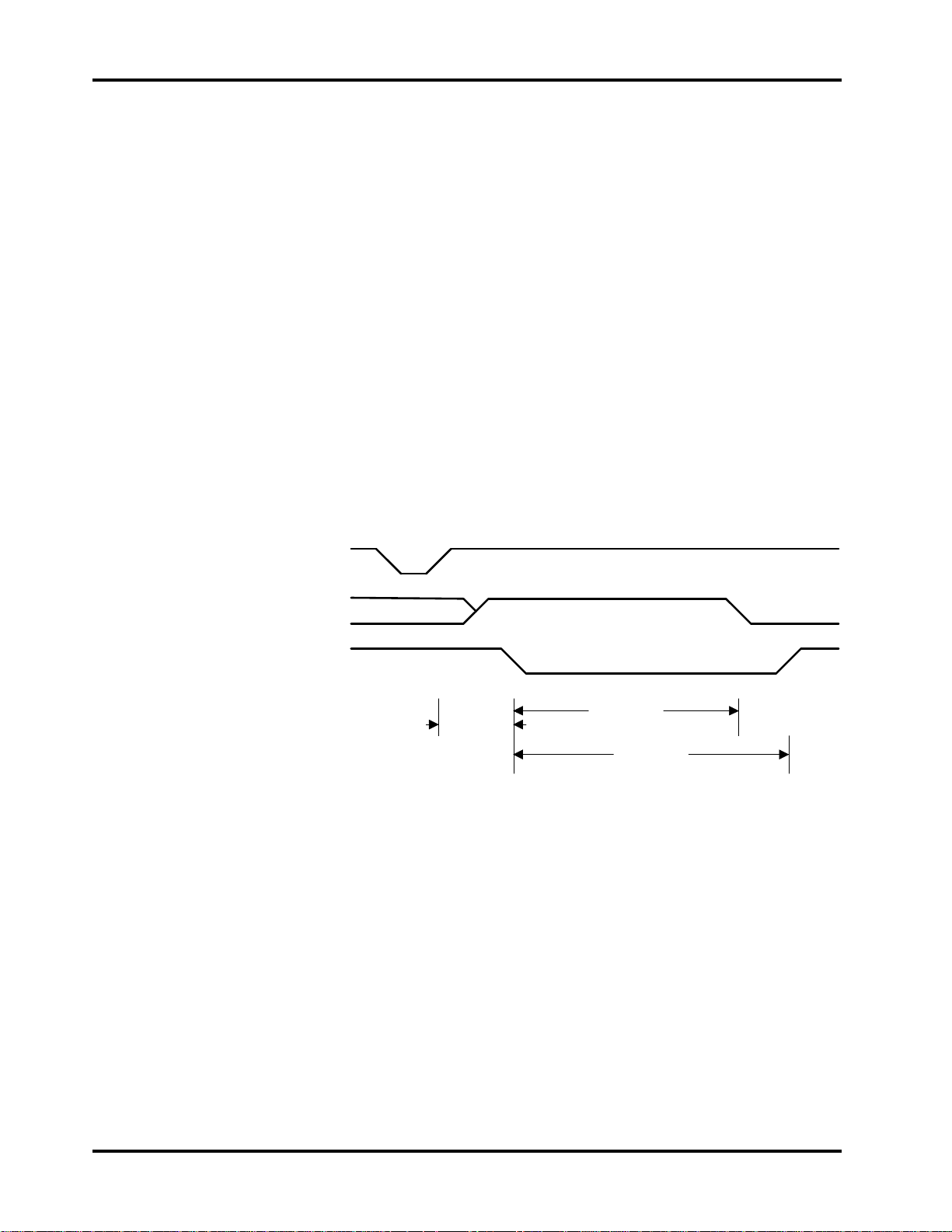
To remedy the problem of the host not knowing when the slave was ready,
Conner developed a backward-compatible solution, which we call Conner
Master/Slave.
In Conner Master/Slave, the use of the Host PDIAG~ signal has been changed
slightly during reset so that the slave will indicate when it will go not busy. Its
use in the diagnostic command has not been changed.
During POR or any host reset, the slave drive activates Host PDIAG~ within
1ms. The master drive waits slightly longer than 1 ms for Host PDIAG~ to be
activated before it determines that no slave is present. The slave then
deactivates Host PDIAG~ when it is ready. The master waits:
• up to 14 seconds for the slave to deactivate Host PDIAG~ on either a POR or
a host reset
• 450 ms for the slave to deactivate Host PDIAG~ on a host software reset
If the master times out, it goes not busy.
In this mode of master/slave, master/slave re-configures with either a hardware
or software reset. A hardware reset is either a Power On Reset (POR) or host
bus reset.
This solution was implemented in generations 4 and greater of Conner drives.
Figure 3-2
Conner Master/Slave Timings
Any Reset
Host PDIAG~
Host DASP~
1 ms
14.5 s *
450 ms
* 1.45 s for hardware reset, 450 ms for software reset
Technical Reference Manual Page 19
Page 28
Chapter 3 How the Drive Operates
ATA/CAM Master/Slave
This industry-standard master/slave solution was developed by the CAM shortly
after the development of the Conner Master/Slave. The polarity of Host PDIAG~
is opposite that of the Conner solution and this is what makes this master/slave
scheme incompatible with the Conner scheme.
At power-on time, the slave deactivates Host PDIAG~ and then activates Host
DASP~ within 1ms of either POR or host reset. Host DASP~ active indicates
that a slave is present. The slave activates Host PDIAG~ when it is ready to
accept commands or after 30 seconds. The drive will inactivate Host DASP~
when it receives the first command or after 30 seconds, whichever occurs first.
This period is reduced to 450ms for a software reset. A hardware reset is either
a POR or host bus reset.
This solution was implemented in generations 4.5 and greater of Conner drives
and is selectable with the A/C jumper or the CAM bit in the feature word.
Figure 3-3
ATA/CAM Master/Slave Timings
Any Reset
Host PDIAG~
Host DASP~
< 30 s
1 m s
* active until first command or 30 s, whichever is less
450 ms
30 s *
450 ms
Page 20 Filepro CFA810A/CFA1080A
Page 29

Installing the Drive
4
Take These Precautions
Installing the Drive
To install the drive, you must:
To protect your equipment from electrostatic damage,
perform the installation at a static-safe workstation. If one is
not available, follow these guidelines:
1. Work in an uncarpeted area.
2. Before removing the equipment from its anti-static bag,
discharge static electricity by touching your computer's
metal chassis (or any other grounded object) while
touching the anti-static bag.
3. Do not touch circuit boards unless instructed to do so.
0170
• set the drive’s jumpers, if desired
• attach a data cable to the drive
• attach power to the drive
• mount the drive
Technical Reference Manual Page 21
Page 30
Chapter 4 Installing the Drive
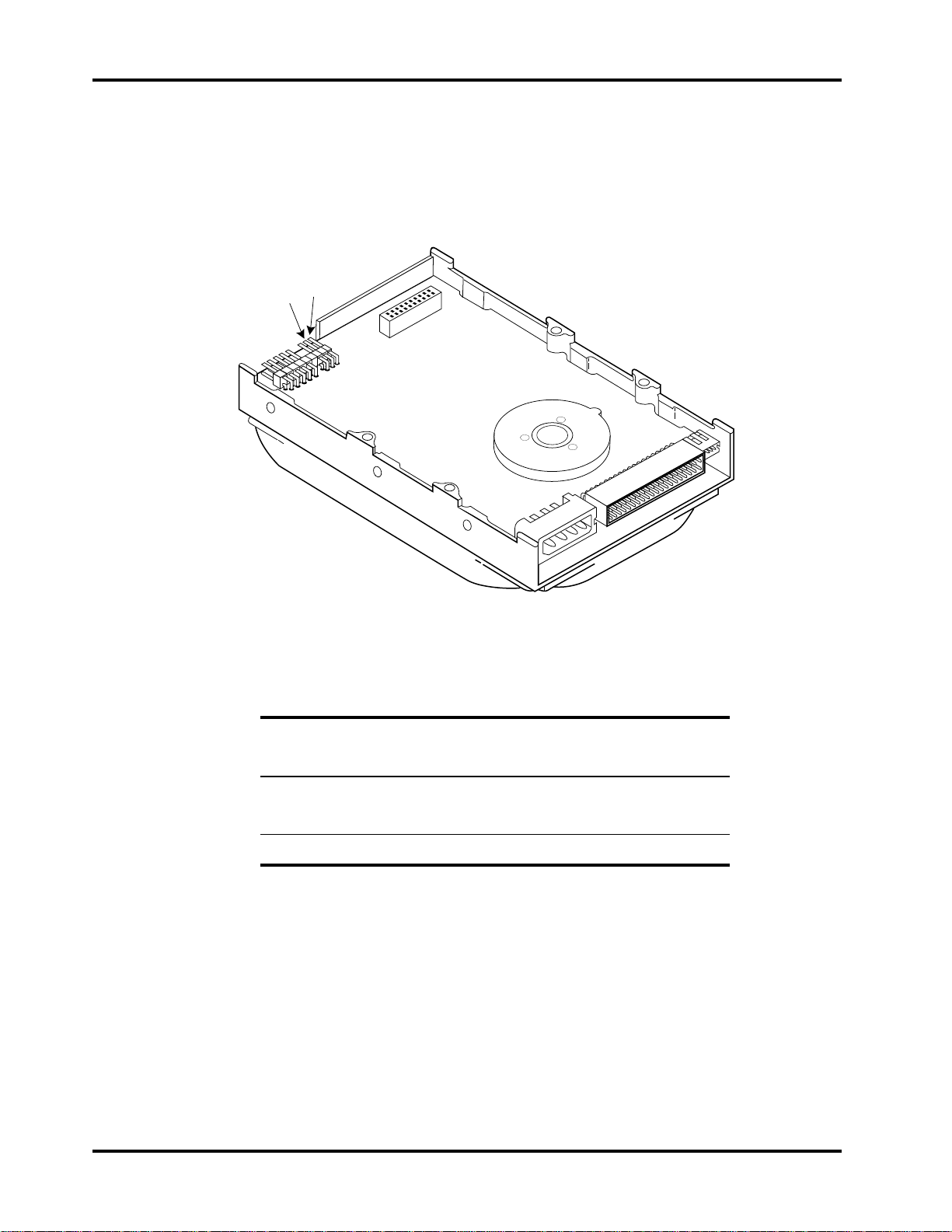
Setting the Drive’s Jumpers
Figure 4-1 shows you how to access the drive’s jumpers.
Figure 4-1
Jumper Locations
C/D
A/C
0175
Here is how you can set these jumpers. Pins described as “reserved” should not
be used.
Pins: Signal: Description
1 and 2
C/D Open: Drive will act as slave.
Closed: Drive will act as master.
3 and 4
A/C Open: Conner master/slave mode
Closed: ATA/CAM master/slave mode
5 to 16
N/A Reserved
Page 22 Filepro CFA810A/CFA1080A
Page 31
Installing the Drive Chapter 4
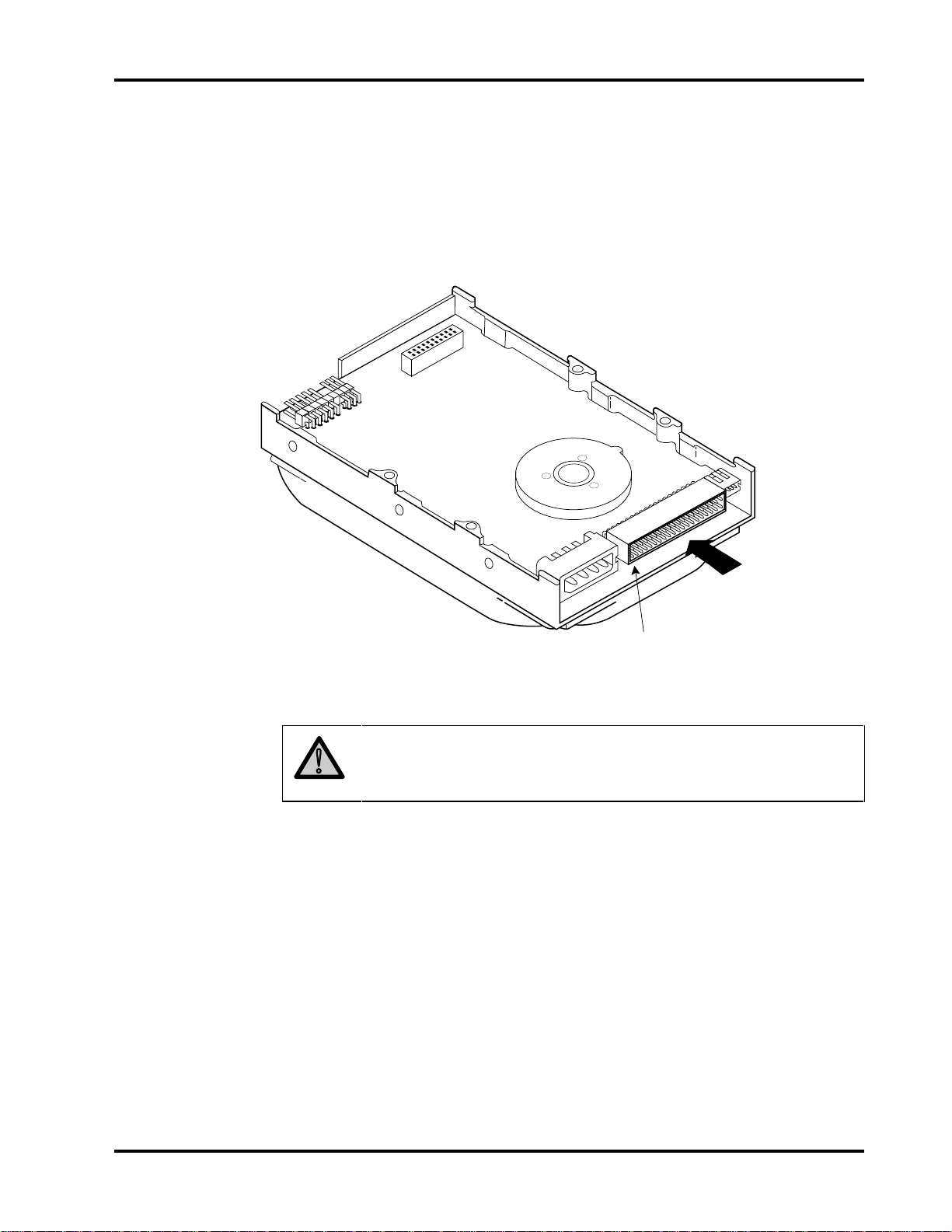
Attaching a Data Cable to the Drive
Attach the data cable from the host to the Task File Interface connector, as
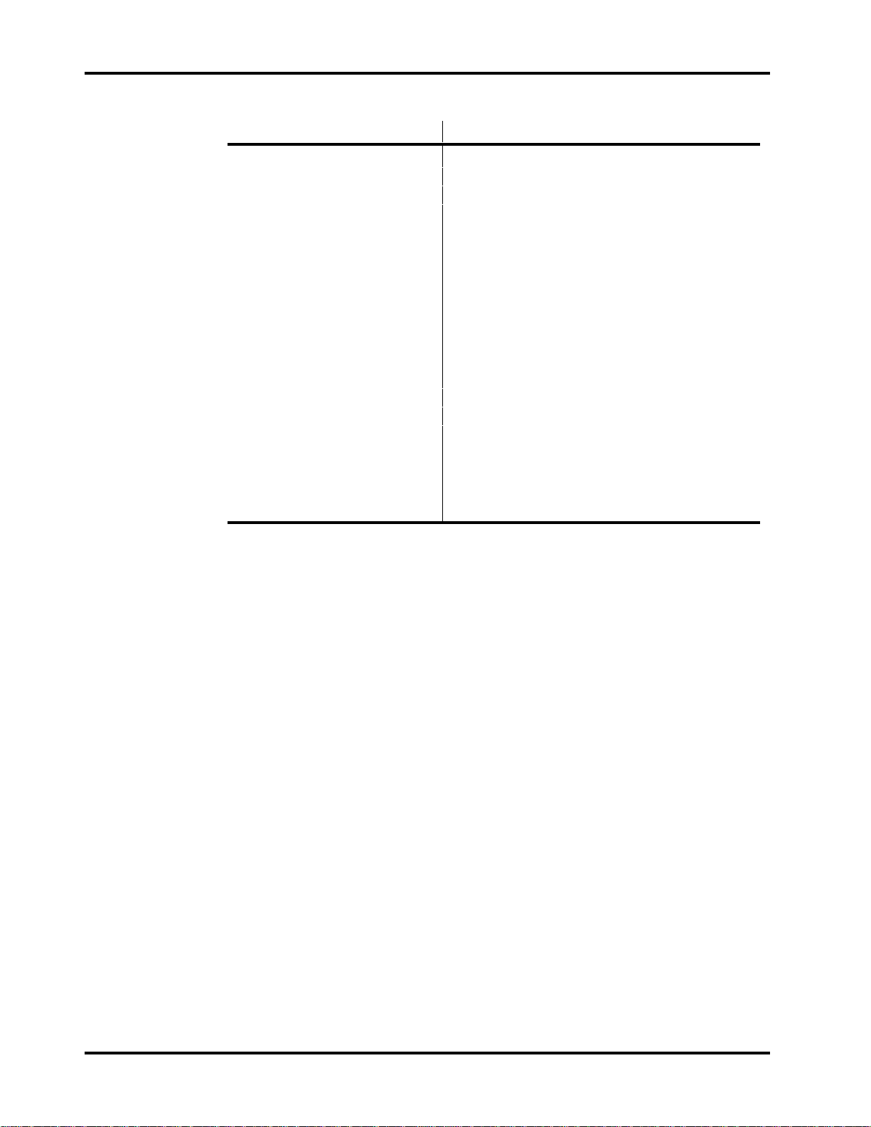
shown in figure 4-2. Refer to the table on the following page for pinout
information.
Figure 4-2
Attaching a Data Cable
0171
40-pin
Task File Interface
Data Connection
Pin 1 (typically indicated by a
colored stripe on the data cable)
Caution: Do not route the data cable next to the drive PCB or
!
any other high frequency or large current switching signals.
Improper drive operation can result from improper cable routing.
Technical Reference Manual Page 23
Page 32
Chapter 4 Installing the Drive
Pin: Signal: Pin: Signal:
01 - HOST RESET 02 GND
03 + HOST DATA 7 04 + HOST DATA 8
05 + HOST DATA 6 06 + HOST DATA 9
07 + HOST DATA 5 08 + HOST DATA 10
09 + HOST DATA 4 10 + HOST DATA 11
11 + HOST DATA 3 12 + HOST DATA 12
13 + HOST DATA 2 14 + HOST DATA 13
15 + HOST DATA 1 16 + HOST DATA 14
17 + HOST DATA 0 18 + HOST DATA 15
19 GND 20 KEY
21 + DMARQ 22 GND
23 - HOST IOW 24 GND
25 - HOST IOR 26 GND
27 + IOCHRDY 28 +Spindle Sync or Cable Select
29 - DACK 30 GND
31 + HOST IRQ14 32 - HOST IO16
33 + ADDR1 34 - HOST PDIAG
35 + ADDR0 36 + ADDR2
37 - HOST CS0 38 - HOST CS1
39 - HOST SLV/ACT 40 GND
The recommended mating connector for the Task File Interface is Molex P/N 1547-5401 or equivalent. You may daisy-chain two drives on this connector. The
maximum cable length is 18 inches.
Page 24 Filepro CFA810A/CFA1080A
Page 33
Installing the Drive Chapter 4
Attaching Power to the Drive
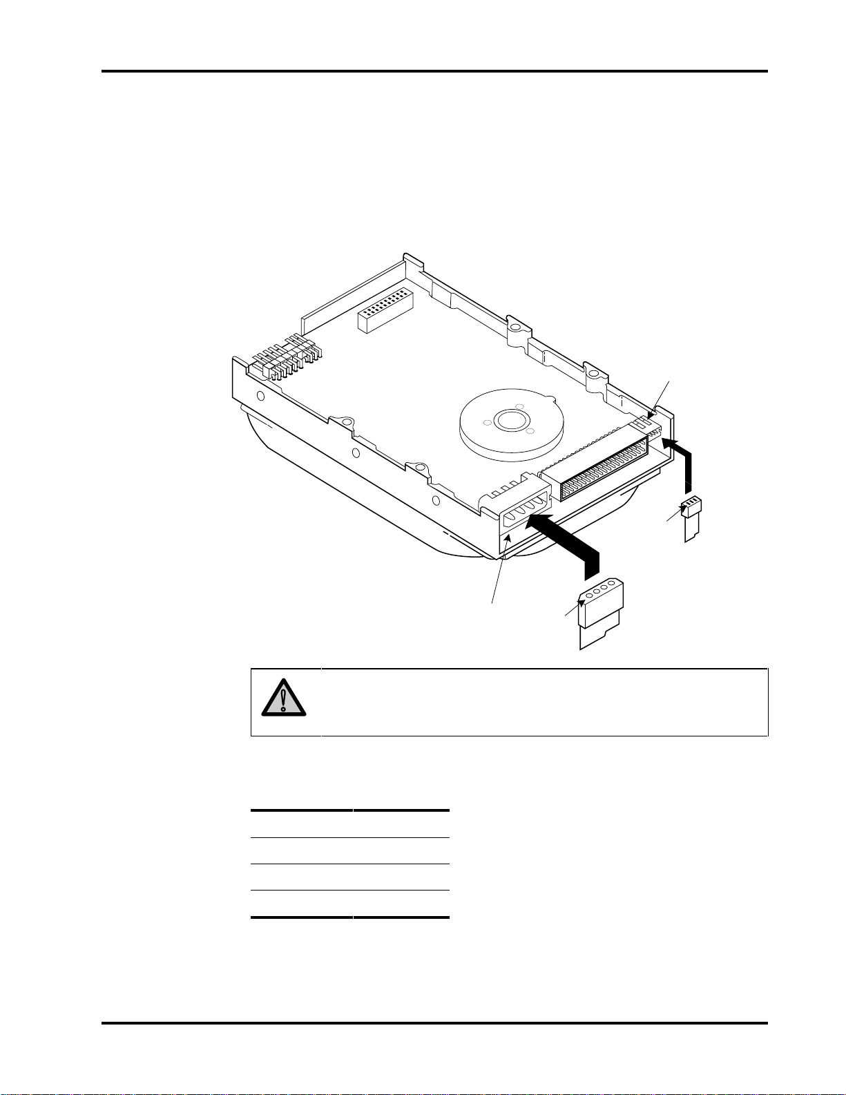
The drive has a standard 4-pin DC power connector and may have an optional,
smaller, 3-pin connector. Power must only be supplied at one source.
Figure 4-3
Attaching a Power Cable
3-pin
0173
power connector
4-pin
power connector
Pin 1
Caution: Do not route the power cable next to the drive PCB or
!
any other high frequency or large current switching signals.
Improper drive operation can result from improper cable routing.
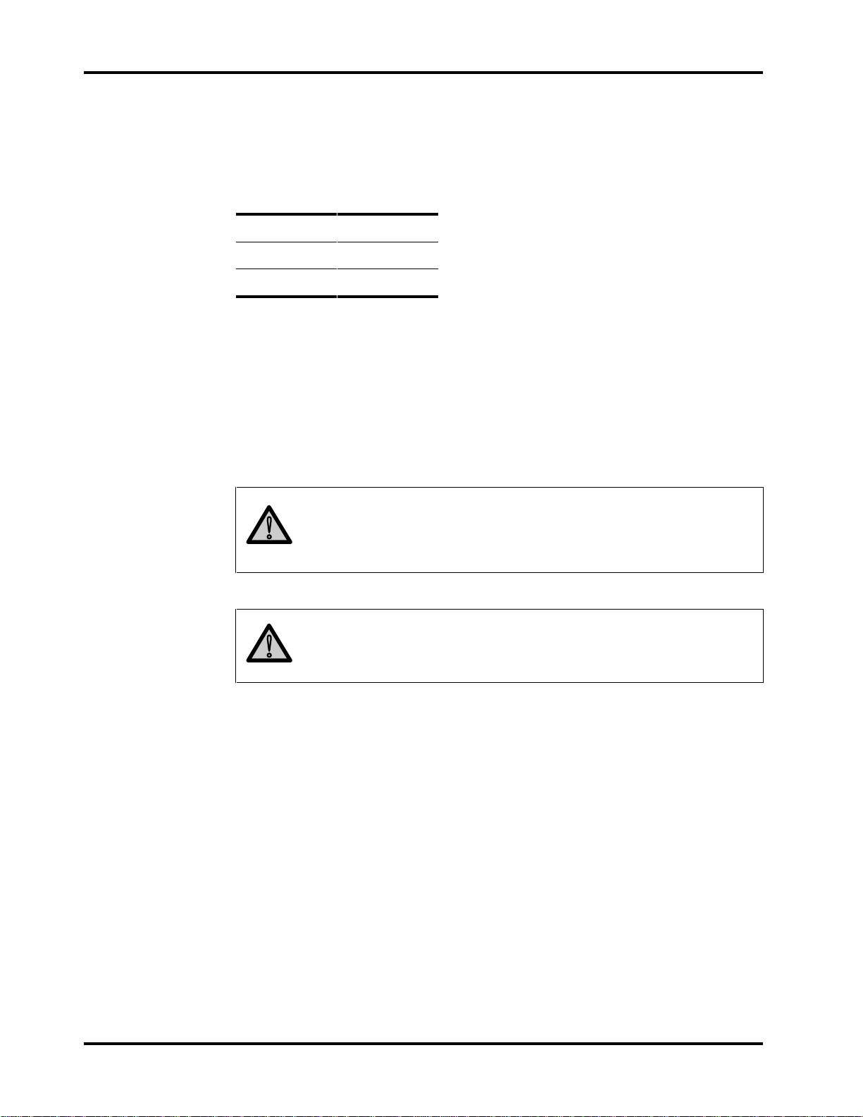
The following table describes the 4-pin power connector pins:
Pin: Signal:
1
2
3
4
+12 Volts
GND
GND
+5 Volts
Pin 1
Technical Reference Manual Page 25
Page 34
Chapter 4 Installing the Drive
The mating connector for the 4 pin connector is AMP 1-480424-0 (housing) and
AMP 60619-4 (loose piece) or 61117-4 (strip) contacts.
The following table describes the 3-pin power connector pins:
Pin: Signal:
1
2
3
The mating connector for the 3-pin connector is Molex series 54-84 (header),
Molex part number 39-01-0033 (housing), and terminal part number 39-00-0031
(loose) or 39-00-0023 (strip).
Mounting the Drive
You can mount the drive either vertically or horizontally. The drive will meet all
performance specifications when mounted at any orientation.
+5 Volts
+12 Volts
GND
Caution: The surface(s) on which you mount the drive should be
!
!
flat and parallel to prevent uneven pressure on the drive.
Mounting the drive on an uneven surface could cause the drive’s
base to deform, degrading drive performance.
Caution: When using the side mounting holes, verify the screw
length to ensure clearance from the drive's printed circuit board
before tightening the screw.
Refer to figur 2-1 in chapter 2 for dimensions and the location of mounting screw
holes.
Page 26 Filepro CFA810A/CFA1080A
Page 35

Host Interface
5
About the Host Interface
The interface between the drive adapter and the drive is called the host
interface. The set of registers in the I/O space of the host that are controlled
through the host interface is known as the task file.
The physical interface from the drive to the host is called the task file
interface and is implemented using a 40-pin connector. The pin assignments
were described in chapter 4.
Definitions of signals are listed beginning on the next page under Signal
Descriptions.
Signal Conventions
The following conventions are used in the discussions that follow:
Signal Levels
• All signals on the host interface shall have the prefix HOST.
• All negatively-active signals shall be further prefixed with a “-” designation.
• All positive-active signals shall be prefixed with a “+” designation.
• Signals whose source is the host are said to be “outbound” and those whose
source is the drive are said to be “inbound.”
All signal levels are TTL compatible. A logic “1” is >2.0 Volts. A logic “0” is from
0.00 Volts to 0.70 Volts. The drive capability of each of the inbound signals is
described below.
Technical Reference Manual Page 27
Page 36

Chapter 5 Host Interface
Signal Descriptions
The following table describes signals on the task file interface.
Signal Name: Dir: Pin: Description:
-HOST RESET O I Reset signal from the host system which is active low during
power-up and inactive thereafter.
GND O 2, 19,
22, 24,
26,30,
40
+HOST DATA I/O 3 - 18 16-bit bi-directional data bus 0 - 15 between the host and the
KEY N/C 20 An unused pin clipped on the drive and plugged on the cable.
+DMARQ I 21 Host DMA request handshake signal.
-HOST IOW O 23 Write strobe, the rising edge of which clocks data from the host
-HOST IOR O 25 Read strobe, which when low enables data from the Task File
+IOCHRDY I
27
Ground between the drive and the host.
drive. The lower 8 bits, HD0 - HD7, are used for register and
ECC access. All 16 bits are used for data transfers. These are
tri-state lines with 24 mA drive capability.
Used to guarantee correct orientation of the cable.
data bus, HD0 - HD15, into a task file register or the data
register on the drive.
on the drive onto the host data bus, HD0 - HD15. The rising
edge of -HOST IOR latches data from the drive at the host.
This signal is negated to extend host transfer cycles when the
controller is not ready to respond.
+SPINDLE
SYNC/CABLE
SELECT
-DACK O 29 Host DMA acknowledge handshake signal.
I/O 28
Optional. This signal may optionally be used for two functions.
Drives are shipped with the interface pin not connected to
either signal unless otherwise requested.
•• Spindle Sync is a signal used by the drives which are
interconnected on the same cable to synchronize their
spindle rotation with each other..
•• Cable Select routes the C/D select to this pin. When set
high, drive D: is selected; when set low, drive C: is
selected.
Page 28 Filepro CFA810A/CFA1080A
Page 37

Host Interface Chapter 5
Signal Name: Dir: Pin: Description:
+HOST IRQ14 I
-HOST IO16 I
-HOST PDIAG I
31
32
34
Interrupt to the host system, enabled only when the drive is
selected and the host activates the -IEN bit in the Digital
Output register. When the -IEN bit is inactive or when the drive
is not selected, this output is in a high impedance state,
regardless of the state of the IRQ bit.
IRQ is reset to zero by a host read of the Status register after
completion of a data transfer phase or a write to the Command
register. This signal is a tri-state line with 8 mA drive capacity.
Indication to the host system that the 16-bit data register has
been addressed and that the drive is prepared to send or
receive a 16-bit data word. This line is tri-state line with 24 mA
drive capacity.
ISA Original Mode. Passed diagnostic. At POR, the slave will
activate -PDIAG within 1 ms. If the master doesn’t see -PDIAG
active after 4 ms, it will assume no slave is present PDIAG will
remain active until the slave is ready to go not busy or 14.0
seconds on a POR. The master will wait 14.5 seconds or until
the slave deactivates -PDIAG on POR before it goes not busy.
The slave will de-activate -PDIAG and go not busy if it is not
ready after the 14.0 seconds. Neither drive will set ready or
seek complete until they have reached full spin speed and are
ready to read/write.
During a software reset, -PDIAG will be activated by the slave
within 1 ms. If the master doesn’t see -PDIAG active after 4 ms
it will assume no slave is present. The slave will not deactivate -PDIAG until it is ready to go not busy or 400 ms. The
master will only wait 450 ms or until the slave deactivates PDIAG before it goes not busy. The slave will only wait 450
milliseconds before it activates -PDIAG and goes not busy.
The slave will not set ready or seek complete until those states
are achieved.
After reset, -PDIAG will be used for the diagnostic command in
the following manner. It is output by the drive if it is the slave
drive, input to the drive if it is the master drive. This low true
signal indicates to a master that the slave has passed its
internal diagnostic command. This line is only inactive high
during execution of the diagnostic command.
Technical Reference Manual Page 29
Page 38

Chapter 5 Host Interface
Signal Name: Dir: Pin: Description:
-HOST PDIAG I
34
ATA/CAM Mode. This signal shall be asserted by the slave to
the master that it has completed diagnostics. A 10K ohm pullup resistor shall be used on this signal by each drive.
Following a POR, a software reset, or a RESET-, the slave will
negate PDIAG- within 1 ms (to indicate to the master that it is
busy). The slave will then assert PDIAG- within 30 seconds to
indicate that it is no longer busy and is able to provide status.
After the assertion of PDIAG-, the slave may be unable to
accept commands until it has finished its reset procedure and is
ready (DRDY =1).
Following the receipt of a valid Execute Drive Diagnostics
command, the slave will negate PDIAG- within 1 ms to indicate
to the master that it is busy and has not yet passed its drive
diagnostics. If the slave is present, then the master will wait for
up to 5 seconds from the receipt of a valid Execute Drive
Diagnostics command for the slave to assert PDIAG-. The
slave should clear BSY before asserting PDIAG-, as PDIAG- is
used to indicate that the slave has passed its diagnostics and is
ready to post status.
If DASP- was not asserted by the slave during reset
initialization, the master will post its own status immediately
after it completed diagnostics and clear the slave status
register to 00 hex. The master may be unable to accept
commands until it has finished its reset procedure and is Ready
(DRDY = 1).
+HOST
A0,A1,A2
-HOST CS0
-HOST CS1
-HOST SLV/ACT I
O
35, 33,36Bit binary coded address used to select the individual registers
O37
O38
39
in the task file.
Chip select decoded from the host address bus. Used to select
some of the host-accessible registers. Note: This signal
should be disabled by the host when data transfers are in
progress.
Chip select decoded from the host address bus. Used to select
three of the registers in the task file.
ISA Mode. Signal from the drive used either to drive an
activity LED whenever the disk is being accessed.
Page 30 Filepro CFA810A/CFA1080A
Page 39
Host Interface Chapter 5
Signal Name: Dir: Pin: Description:
-DASP I
39
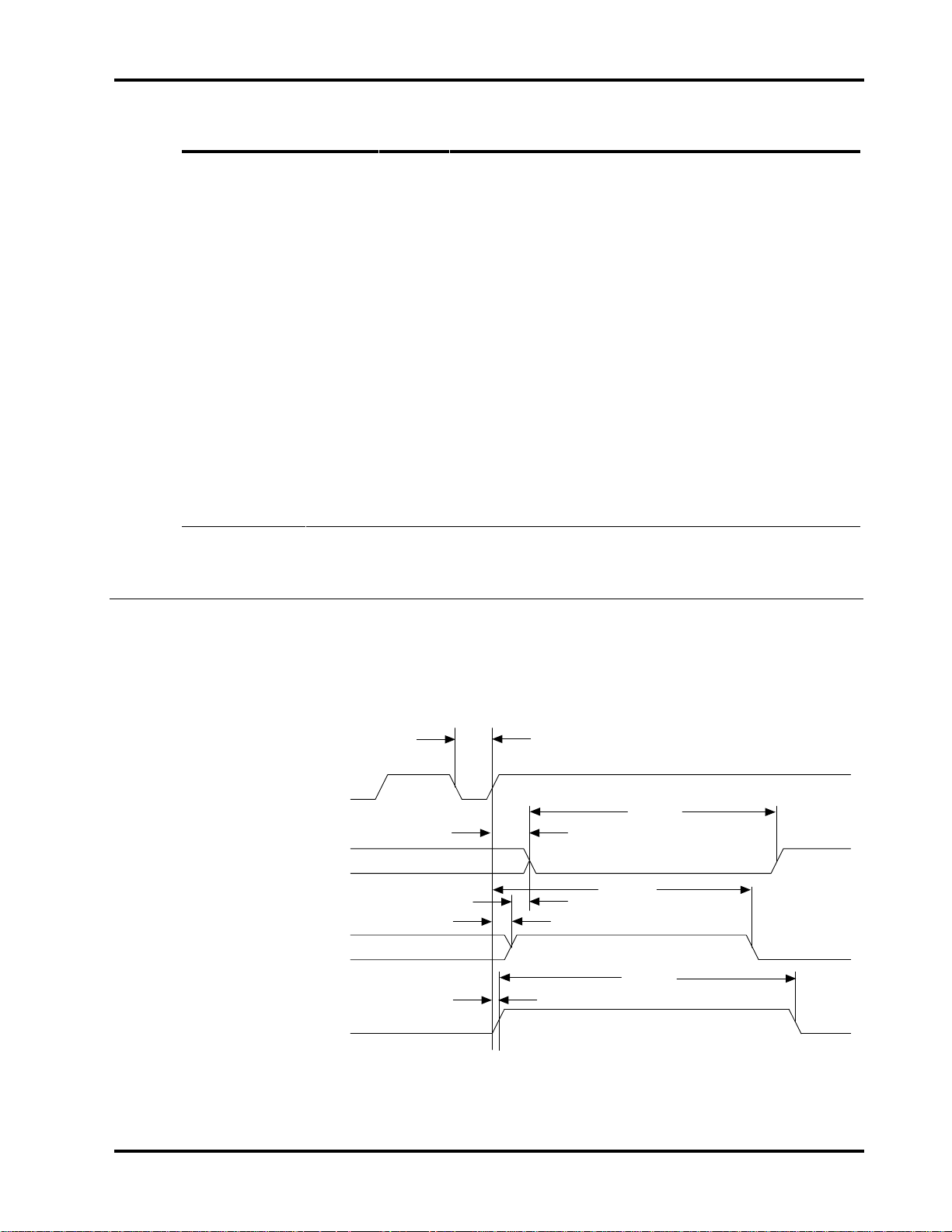
ATA/CAM Mode. DASP- (drive active/slave present). This is a
time-multiplexed signal which indicates that a drive is active, or
that the slave is present. This signal is an open-collector
output and each drive has a 10K pull-up resistor.
During power-on initialization or after RESET is negated,
DASP- shall be asserted by the slave within 400 ms to indicate
that the slave is present.
The master shall allow up to 450 ms for the slave to assert
DASP-. If the slave is not present, the master may assert
DASP- to drive an activity LED.
DASP- shall be negated following acceptance of the first valid
command by drive 1 or after 31 seconds, whichever comes
first.
Any time after negation of DASP-, either drive may assert
DASP- to indicate that a drive is active.
ATA/CAM Master/Slave Reset Timing
Figure 5-1 illustrates the reset sequence for the ATA/CAM Master/Slave method.
Figure 5-1
ATA/CAM Reset Sequence
T
M
-Reset
-DASP
-PDIAG
BSY bit in
Status Register
T
R
T
D
T
D
T
N
T
S
T
Q
T
B
0165
Technical Reference Manual Page 31
Page 40

Chapter 5 Host Interface
Description Label POR Value Soft Reset Value
-Reset width (min) T
-DASP asserted (max) T
-DASP after Reset (max) T
Slave DIAG complete (max) T
Drive BSY (max) T
-DASP after -PDIAG (min) T
BSY status after Reset (max) T
-PDIAG after Reset (max) T
M
S
R
Q
B
D
N
A
25µs N/A
31s 31s
450ms N/A
30s 30s
31s 31s
>0 N/A
400ns 400ns
N/A 1ms
Notes:
1. -DASP is asserted by both the master and the slave. The signal on the bus
is the “wired OR” of -DASP from both drives. The master de-asserts -DASP
within 1ms after reset and waits for up to 450ms for the slave to assert
-DASP to signal its presence.
2. During a reset condition, the host BIOS checks drive 0 for BSY to be reset.
Drive 0 monitors the -PDIAG signal from the slave. When the slave
completes its diagnostics, it clears its BSY and asserts -PDIAG. The master
will wait for up to 31 seconds for -PDIAG, then clears its BSY and de-asserts
-DASP.
Page 32 Filepro CFA810A/CFA1080A
Page 41
Host Interface Chapter 5
ISA/Conner Master/Slave Reset Timing
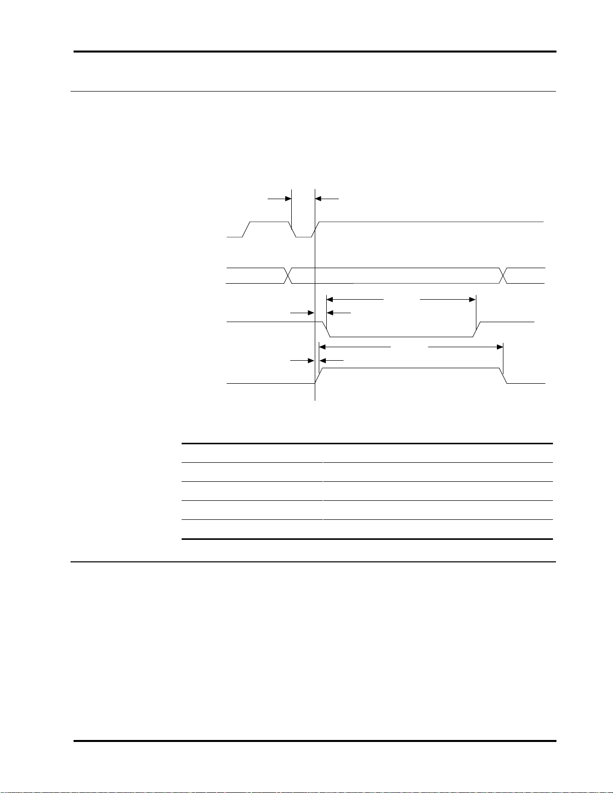
Figure 5-2 illustrates the reset sequence for the ISA and Conner Master/Slave
methods.
Figure 5-2
ISA and Conner Reset Sequence
T
M
-Reset
-DASP
T
Q
-PDIAG
T
P
T
B
BSY bit in
Status Register
T
N
Description Label POR Value Soft Reset Value
-Reset width (min) T
Slave DIAG complete (max) T
Drive BSY (max) T
BSY status after Reset (max) T
-PDIAG after Reset (max) T
M
Q
B
N
P
25µs N/A
14s 450ms
14.5s 450ms
400ns 400ns
1ms 1ms
0166
Technical Reference Manual Page 33
Page 42
Chapter 5 Host Interface
Host PI0 16-Bit Timing Values
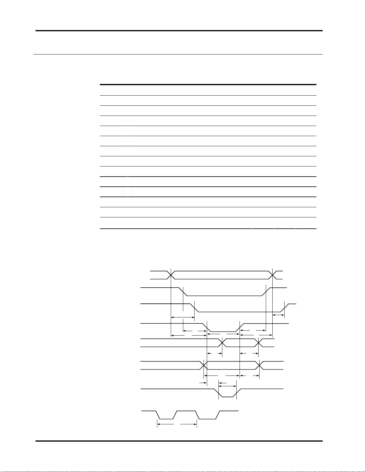
The values* in the table below refer to the timing diagram in figure 5-3.
Symbol Parameter Units Min: Max: Unit:
T
1
T
2
T
3
T
4
T
5
T
6
T
7
T
8
T
9
T
10
T
11
T
12
T
13
T
14
*
Under conditions equivalent to a 330 ohm pullup and a 56pf load. Cable type and length
may affect the values measured at the drive or host interface.
A[0:2] valid until -IOCS16 valid 15 ns
-IOCS16 valid after A[0:2] invalid 14 ns
A[0:2] valid until -IOR or -IOW valid 5 ns
A[0:2] valid after -IOR or-IOW invalid 10 ns
-CS0 or -CS1 valid until -IOR or -IOW valid 10 ns
-CS0 or -CS1 valid after -IOR or IOW invalid 10 ns
-IOW or -IOR pulse width 60 ns
Read Data valid after -IOR valid 25 ns
Read Data valid after -IOR invalid 20 ns
Write Data valid until -IOW invalid 5 ns
Write Data valid after -IOW invalid‘ 5 ns
-IOR or -IOW valid until -IOCHRDY valid 15 ns
-IOCHRDY pulse width 1,250 ns
-IOR/-IOW cycle time (w/ IOCHRDY) 180s ns
Figure 5-3
Interface PIO Timing Diagram
A[0:2]
-HCS0/-HCS1
-IOCS16
-IOR/-IOW
HDB[0:15]
(read)
HDB[0:15]
(write)
-IOCHRDY
-IOR or -IOW CYCLE TIME
-IOR/-IOW
T
1
T
T
5
T
3
T
14
T
7
T
8
T
10
T
12
T
13
6
T
4
T
9
T
11
T
2
0242
Page 34 Filepro CFA810A/CFA1080A
Page 43
Host Interface Chapter 5
Host Demand Mode DMA 16-bit Interface Timing Values
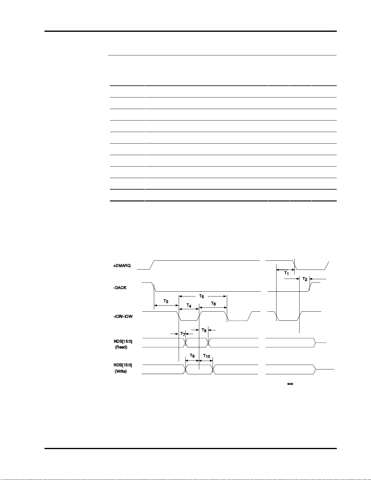
The values* in the table below refer to the timing diagram in figure 5-4.
Symbol: Parameter: Min: Max: Unit:
T
1
T
2
T
3
T
4
T
5
T
6
T
7
T
8
T
9
T
10
* Under conditions equivalent to a 330 ohm pull-up and a 56pf load. Cable type and length
may affect the values measured at the drive or host interface
-IOR/-IOW valid to +DMARQ invalid 40 ns
-IOR/-IOW invalid to -DACK invalid 5 ns
-DACK valid to -IOR/-IOW valid 0 ns
-IOR/-IOW pulse width 60 ns
-IOR/-IOW cycle time 150 ns
-IOR/-IOW high 50 ns
-IOR valid until HDB[15:0] valid 25 ns
-IOR invalid to HDB[15:0] invalid 20 ns
HDB[15:0] valid until -IOW invalid 5 ns
HDB[15:0] valid after -IOW invalid 5 ns
Figure 5-4
Interface DMA Timing Diagram
+DMARQ
T
1
-DACK
T
T
3
5
T
T
4
6
T
2
-IOR/-IOW
T
8
T
T
9
10
0243
HDB[15:0]
(Read)
HDB[15:0]
(Write)
T
7
Technical Reference Manual Page 35
Page 44

Chapter 5 Host Interface
Page 36 Filepro CFA810A/CFA1080A
Page 45

Register Addresses and Functions
Host Address Decoding
The host computer addresses the drive using programmed I/O. This method
requires that:
• a proper chip select be asserted
• the desired register address be placed on the three host address lines
(HA2 - HA0)
•a Read or Write strobe (-HOST IOR/-HOST IOW) is given to the chip
The host generates two independent chip selects on the interface.
• The high order chip select, -HOST CS1, is used to access register 3F6 or 3F7.
• The low order chip select, -HOST CS0, is used to address registers 1F0
through 1F7.
6
ECC bytes are transferred on bits 7 - 0.
The host data bus 15 - 8 is only enabled when:
• -IO16 is active
• the host is addressing the data register for transferring data
• the host is not transferring ECC bytes, which are only transferred if the
operation is a Read Long or Write Long
The I/O map on the next page defines all of the register addresses and the
functions for these I/O locations.
The sections that follow the I/O map describe each of the registers.
Technical Reference Manual Page 37
Page 46

Chapter 6 Register Addresses and Functions
Write Function
No Operation
Invalid Address
Not Used
Not Used
Data Register
Features Register
Sector Count
Sector Number
Cylinder Low
Cylinder High
SDH Register
Command Register
Digital Output Register
Not Used
Addr* -CSO -CS1 HA2 HA1 HA0 Read Function
1 1 x x x No Operation
0 0 x x x Invalid Address
1 0 0 x x High Impedance
1010xHigh Impedance
1F0
1F1
1F2
1F3
1F4
1F5
1F6
1F7
3F6
3F7
01000Data Register
01001Error Register
01010Sector Count
01011Sector Number
01100Cylinder Low
01101Cylinder High
01110SDH Register
01111Status Register
10110Alternate Status Register
10111Drive Address Register
x = don't care
* These I/O port addresses are listed for programmer reference. They are a function of I/O decoding in the
Host Adapter. These addresses are required for compatibility with most AT BIOS.
Page 38 Filepro CFA810A/CFA1080A
Page 47

Register Addresses and Functions Chapter 6
Addressing the Data
There are two methods of addressing the sectors on the disk drive.
Cylinder-Head-Sector (CHS) Mode
The first method, which is the traditional approach, uses Cylinder-Head-Sector
(CHS) addressing. Most disk drives today exceed the number of cylinders limit
of DOS or use zone recording (different number of sectors per track in each zone)
so the parameters reported by the drive in the Identify Drive command are
logical translations done by the drive. BIOS CHS-toCHS translation allows the
task file registers to address up to 8GB of data.
Logical Block Addressing (LBA) Mode
The second method uses Logical Block Addressing (LBA), which is common to
SCSI. This method re-defines the content of the Task File registers, which are
described later in this chapter. This drive operates with either CHS or LBA
addressing by responding to the switch in the SDH register. The registers
affected by LBA mode are the Sector Number, Cylinder Low, Cylinder
High, and SDH. The use of these registers allows a 28-bit address space
capable of handling up to 128GB of data.
In LBA mode, the sectors on the disk are linearly mapped with the first logical
block (LBA 0) defined as Cylinder 0, Head 0, Sector 1. The subsequent logical
blocks are defined by the formula:
LBA = [(cylinder * no. of heads + heads) * sectors/track] + (sector - 1)
Technical Reference Manual Page 39
Page 48

Chapter 6 Register Addresses and Functions
Descriptions of the Registers
The following sections describe the registers used for read and write functions.
In these descriptions, unused write bits should be treated as “don’t cares” and
other unused bits should be read as zeroes.
Data Register
Port Select: 1F0
Chip Select: HOST CS0
Register Address: 0
Function: Read/Write
Description: This is the register:
• through which all data is passed on Read and Write commands
• to which the sector table is transferred during Format commands
• to which data associated with the Identify command is transferred
All transfers are high speed 16-bit I/O operations except for ECC bytes
transferred during R/W Long commands, which are slower 8-bit operations that
occur after the transfer of the data.
Data is stored on the disk with the Least Significant Byte (LSB) first, then the
Most Significant Byte (MSB) for each word. This is important to remember
when testing the ECC circuitry.
Page 40 Filepro CFA810A/CFA1080A
Page 49

Register Addresses and Functions Chapter 6
Bit 2
ABRT
Error Register
Port Address: 1F1
Chip Select: -HOST CS0
Register Address: 1
Function: Read only
Description: This register contains status from the last command executed by
the drive.
The contents of this register are only valid when the error bit (ERR) is set in the
Status Register, unless the drive has just powered up or completed execution of
its internal diagnostic, in which case the register contains a status code. The
status codes are discussed in chapter 7 in the description of the Diagnostic
command.
The bits in the register are defined below:
Bit 7 Bit 6 Bit 5 Bit 4 Bit 3
BBK UNC not
used
where:
• BBK indicates that a bad block mark was detected in the requested sector’s
ID field. A bad block mark is not created in the factory, but only when
requested in the format command.
• UNC indicates that a non-correctable data error has been encountered.
• IDNF indicates that the requested sector’s ID field could not be found.
• ABRT indicates that the requested command has been aborted due to a
drive status error (not ready, write fault, etc.) or because the command code
is invalid.
• TK0 indicates that track 0 has not been found during a recalibrate
command.
For other drives Bit 0 is AMNF (Address Mark Not Found.) This is not used on
Conner drives.
IDNF not
used
Bit 1 Bit 0
TK0 not
used
Technical Reference Manual Page 41
Page 50

Chapter 6 Register Addresses and Functions
Features Register (formerly Write Precomp Register)
Port Address: 1F1
Chip Select: -HOST CS0
Register Address: 1
Function: Write only
Description: This register was previously used to set write precompensation in
non-intelligent (pre-IDE) disk drives. This drive uses this register for commands
EF and F1 through F6. The ATA specification defines this register as the
Features register.
Sector Count
Port Address: 1F2
Chip Select: -HOST CS0
Register Address: 2
Function: Read/Write
Sector Number
Description: This register defines the number of sectors of data to be
transferred on read or write commands.
If the value in this register is zero, a count of 256 sectors is specified. This count
is decremented as each sector is read, such that the register contains the number
of sectors left to access in the event of an error in a multi-sector operation.
The contents of this register define the number of sectors per track when
executing an Initialize Drive Parameters command. This register is also
used in the power commands to provide the power-down time-out parameter and
status.
Port Address: 1F3
Chip Select: -HOST CS0
Register Address: 3
Function: Read/Write
CHS Description: This register contains the starting sector number for any
disk access.
LBA Description: This register contains bits 0-7 of the logical block address.
At the completion of each sector and at the end of the command, this register is
updated to reflect the last sector read correctly or the sector on which an error
occurred. During multiple sector transfers, this register is updated to point at
the next sector to be read/written if the previous sector’s operation was
successful.
Page 42 Filepro CFA810A/CFA1080A
Page 51

Register Addresses and Functions Chapter 6
Cylinder Low
Port Address: 1F4
Chip Select: -HOST CS0
Register Address: 4
Function: Read/Write
CHS Description: This register contains the low-order 8 bits of the starting
cylinder number for any disk access.
LBA Description: This register contains bits 8-15 of the logical block address.
At the completion of each sector and at the end of the command, this register is
updated to reflect the current drive address.
Cylinder High
Port Address: 1F5
Chip Select: -HOST CS0
Register Address: 5
Function: Read/Write
CHS Description: This register contains the high-order bits of the starting
cylinder number for any disk access. Most BIOS will only use the first two bits
of this register, forming a 10-bit cylinder address.
LBA Description: This register contains bits 16-23 of the logical block address.
At the completion of each sector, and at the end of the command, this register is
updated to reflect the current drive address.
Technical Reference Manual Page 43
Page 52
Chapter 6 Register Addresses and Functions
Bit 1
SDH Register
Port Address: 1F6
Chip Select: -HOST CS0
Register Address: 6
Function: Read/Write
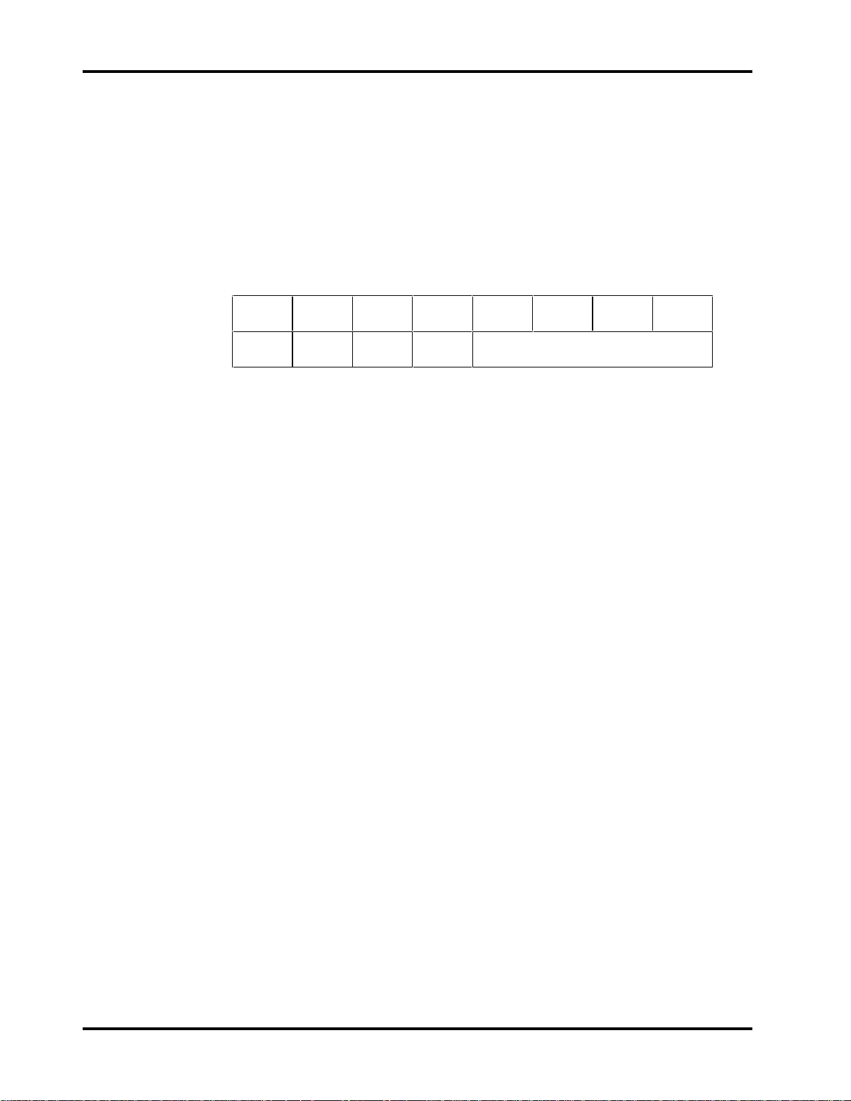
Description: This register contains the drive and head numbers, as defined
below:
Bit 7 Bit 6 Bit 5 Bit 4 Bit 3 Bit 2
1 LBA 1 DRV HEAD
where:
• DRV is the binary encoded drive select number. When this bit is reset, the
master drive is selected, and when this bit is set, the slave drive is selected.
While both drive’s Task File registers are always written, this bit selects
which drive will respond and execute a command.
• LBA is the binary coded address mode select. When L = 0, addressing is by
CHS mode. When L = 1, addressing is by LBA mode. This bit was RSVD
(reserved) for use by the host and set to 0.
• HEAD
CHS Description: This is the four-bit binary encoded head select number.
LBA Description: This register contains bits 24-27 of the logical block
address.
At the completion of each sector and at the end of the command, this
register is updated to reflect the currently selected head.
Bit 0
Page 44 Filepro CFA810A/CFA1080A
Page 53

Register Addresses and Functions Chapter 6
Bit 2
CORR
Status Register
Port Address: 1F7
Chip Select: -HOST CS0
Register Address: 7
Function: Read only
Description: This register contains the drive/controller status. The contents of
this register are updated at the completion of each command.
If the Busy bit is active, no other bits are valid. The host reading this register
when an interrupt is pending is considered to be the interrupt acknowledge, and
any pending interrupt is therefore cleared whenever this register is read.
The bits in this register are defined below:
Bit 7 Bit 6 Bit 5 Bit 4 Bit 3
BSY DRDY DWF DSC DRQ
where:
• BSY is the Busy bit, which is set whenever the drive has access to the Task
File registers and the host is locked out from accessing the Task File. This
bit is set under any the following circumstances:
− At activation of the Host Reset pin in the interface, or at activation of
the software reset bit in the digital output register.
− Immediately upon host write of the command register with a Read,
Read Long, Read Buffer, Seek, Recalibrate, Initialize Drive
Parameters, Read Verify, Identify, or Execute Drive Diagnostic
command.
− Immediately following transfer of 256 words of data after host write of
the command register with a Write, Format Track, or Write Buffer
command.
− Immediately following transfer of 256 words of data and the ECC bytes
after a host write of the Command register with a Write Long
command.
Bit 1 Bit 0
IDX ERR
When BSY is active, any host read of a Task File register is inhibited and
the Status register is read instead.
• DRDY is the drive ready indication. When there is an error, this bit is not
changed until the Status register is read by the host, at which time the bit
again indicates the current readiness of the drive. This bit will be reset at
power-up and remain reset until the drive is up to speed and ready to accept
a command.
Technical Reference Manual Page 45
Page 54

Chapter 6 Register Addresses and Functions
Bit 1
IDX
• DWF is the drive write fault bit. When there is an error, this bit is not
changed until the Status register is read by the host, at which time the bit
again indicates the current write fault status.
• DSC is the drive seek complete bit. It is an indication that the actuator is
on track. When there is an error, this bit is not changed until the Status
register is read by the host, at which time the bit again indicates the current
readiness of the drive. This bit will be reset at power-up and will remain
reset until the drive is up to speed and ready to accept a command.
• DRQ is the data request bit, which indicates that the drive is ready for
transfer of a word or a byte of data between the host and the Data register.
• CORR is the corrected data bit, which is set:
− when a correctable data error has been encountered and the data has
been corrected
− on a read verify if any sector was corrected the bit is valid
This condition will not terminate either a Multi-Sector Read or a Read
Multiple command.
• IDX is the index bit which is set once per disk revolution.
• ERR is the error bit, which indicates that the previous command ended in
some type of error. The other bits in the Status register, as well as the bits
in the Error register, will have additional information as to the cause of the
error.
Alternate Status Register
Port Address: 3F6
Chip Select: -HOST CS1
Register Address: 6
Function: Read only
Description: This register contains the same information as the Status register
in the Task File. The only difference is that reading this register does not imply
interrupt acknowledge to reset a pending interrupt.
The bits in this register are defined below:
Bit 7 Bit 6 Bit 5 Bit 4 Bit 3 Bit 2
Bit 0
BSY DRDY DWF DSC DRQ CORR
See the description of the Status register for definitions of the bits in this
register.
ERR
Page 46 Filepro CFA810A/CFA1080A
Page 55

Register Addresses and Functions Chapter 6
Bit 2
SRST
Digital Output Register
Port Address: 3F6
Chip Select: -HOST CS1
Register Address: 6
Function: Write only
Description: This register contains two control bits as follows:
Bit 7 Bit 6 Bit 5 Bit 4 Bit 3
not
used
where:
• SRST is the host software reset bit. The drive is held reset when this bit is
active, and enabled when this bit is inactive.
• -IEN is the enable bit for this disk drive interrupt to the host.
− When this bit is active (=0) and the drive is selected, the host interrupt,
− When this bit is inactive (=1), or the drive is not selected, the +IRQ pin
not
used
+IRQ, is enabled through a tri-state buffer to the host.
will be in a high impedance state, regardless of the presence or absence
of a pending interrupt.
not
used
not
used
not
used
Bit 1 Bit 0
-IEN not
used
Technical Reference Manual Page 47
Page 56

Chapter 6 Register Addresses and Functions
Bit 1
-DS1
Drive Address Register
Port Address: 3F7
Chip Select: -HOST CS1
Register Address: 7
Function: Read only
Description: This register loops back the drive select and head select addresses
of the currently selected drive.
The bits in this register are as follows:
Bit 7 Bit 6 Bit 5 Bit 4 Bit 3 Bit 2
RSVD -WTG -HS3 -HS2 -HS1 -HS0
where:
• RSVD is reserved and negated by the drive. When the host reads the drive
address register, this bit must be in a high impedance state.
• -WTG is the write gate bit, which is active when writing to the disk drive is
in progress.
• -HS3 through -HS0 are the one’s complement of the binary coded address
of the currently-selected head. For example, if -HS3 through -HS0 are 1 1 0
0, respectively, head 3 is selected.
• -DS1 is the drive select bit for drive 1, and should be active when drive 1 is
selected and active.
• -DS0 is the drive select bit for drive 0, and should be active when drive 0 is
selected and active.
Bit 0
-DS0
☞☞ Note: Bit 7 is not driven for compatibility with the floppy drive address space. If your system is
different, you may have to drive this bit when this register is read.
Command Register
Port Address: 1F7
Chip Select: -HOST CS0
Register Address: 7
Function: Write only
Description: The eight-bit code written to this register passes the command
from the host to the drive. Command execution begins immediately after this
register is written.
Refer to chapter 7 for a list of executable commands with the command codes
and necessary parameters for each command.
Page 48 Filepro CFA810A/CFA1080A
Page 57

Register Addresses and Functions Chapter 6
b1
1
0
x
0
0
1
p
0
0
L
0
0
x
x
1
1
0
1
0
L
0
This I/O map defines the register addresses and functions for these I/O locations.
For ease of reference, the commands are listed in alphabetical order.
Command Code Parameters:
Command: b7 b6 b5 b4 b3 b2
b0 SC SN CY
SDH
PR
Conner Specific
Execute Drive Diagnostic
Format Track
Identify Drive
Init. Drive Parameters
Physical Seek
Power Commands
Read DMA
Read Multiple
Read Sector(s)
Read Sector Buffer
Read Verify Sector(s)
Recalibrate
Seek
Set Features
Set Multiple Mode
Translate
Write DMA
Write Multiple
Write Sectors
Write Sector Buffer
100110
100100
0101xx
111011
100100
111100
11100p
110010
110001
001000
111001
010000
0001xx
0111xx
111011
110001
111100
110010
110001
001100
111010
0yyydn
0nnndn
xnnyyn
0nnndn
1ynnyn
0yyyyy
pynndn
r yyyyn
0yyyyn
r yyyyn
0enedn
r yyyyn
xnnndn
xnnyyn
1ynndy
0ynndn
1nyyyy
r yyyyn
1yyyyn
r yyyyn
0enedn
where:
• L is the long bit, if 1, R/W Long commands are executed, if 0, normal R/W
commands are performed.
• r is the retry bit; 0 = retries are enabled, 1 = retries are disabled. Retries
that may be enabled/disabled are those on ECC and data errors. When
retries are disabled at the start of a command, they are always
automatically enabled at the end of the command.
• SC is the sector count register.
• SN is the sector number register.
• CY is the cylinder registers.
• SDH is the drive/head register.
• PR is the features (write precomp) register.
• y means the register contains a valid parameter for this command. For the
drive/head register, y means that both the drive and head parameters are
used.
Technical Reference Manual Page 49
Page 58

Chapter 6 Register Addresses and Functions
• n means the register does not contain a valid parameter for this command.
• d means only the drive parameter is valid and not the head parameter.
• p is a valid bit for power commands E0 - E3 and E5 - E6.
• e means the registers contain valid parameters when performing extended
commands.
• x = don’t care.
Page 50 Filepro CFA810A/CFA1080A
Page 59

Command Set
Command Register
All commands are decoded from the Command Register. The drive’s host
interface shall be programmed by the host computer to perform commands and
will return status to the host at command completion.
To issue a command, the host must:
• load the pertinent registers in the Task File
• activate the interrupt enable bit, -IEN, in the Digital Output register
• write the command code to the Command register
Execution begins as soon as the Command register is written.
The following sections describe the drive’s supported command set. For ease of
reference, the commands are listed in alphabetical order.
7
Technical Reference Manual Page 51
Page 60

Chapter 7 Command Set
Conner Specific
Command Number: 9A hex
Description: The Conner drive provides vendor-unique commands to allow for
certain operations not provided by the standard command set. The Sector
Number register must be set to 9A hex and the specific command in the Sector
Count register. The Cylinder High and Low registers are used to pass any bytes
used in a write operation.
The Conner specific command has the following decodes:
Decode: Description:
00 hex
01 hex
02 hex
03 hex
04 hex
05 hex
06 hex
07 hex
08 hex*
09 hex*
0A-FF hex
* only valid on drives which implement Conner Power commands
The following sections describe these decodes in more detail.
Get Feature Word
Reserved
Read drive switches
Abort command
Reserved
Reserved
Abort command
Abort command
Power lock
Power unlock
Reserved
Page 52 Filepro CFA810A/CFA1080A
Page 61

Command Set Chapter 7
Get Drive Feature word (00)
This command fetches the drive feature word and returns it in the Cylinder
High and Cylinder Low registers. The bit meaning is as follows:
Bit: Description:
15
14
13
12
11
10
9
8
7
6
5
4
3
2
1
0
Reserved
Reserved
Customer Reserved
Customer Reserved
Enable PIO Mode 2 at power on
Reserved
Reserved
ATA/CAM mode = 1
Reserved
Customer Reserved
Reserved Enable no spin on POR
Reserved
Disable Read Look Ahead Caching
Enable Write Caching
Reserved
Customer Reserved
It is important to read the Feature word and then only change the bits of
interest leaving the other bits unaffected using specific commands supported by
this drive.
Technical Reference Manual Page 53
Page 62

Chapter 7 Command Set
Read the Drive Switches (02)
This command returns the drive switches in the Cylinder Low Register. The bit
meaning is as follows:
Bit: Description:
7
6
5
4
3
2
1
0
Reserved
Reserved
-C/D
Reserved
Reserved
Reserved
Reserved
Reserved
Power Lock (08)
This command prevents the drive from spinning down, and spins the drive up if
the drive had been spun down.
Power Unlock (09)
This allows the drive to respond to the Power command and re-enables the
power down time if applicable.
Page 54 Filepro CFA810A/CFA1080A
Page 63

Command Set Chapter 7
Execute Drive Diagnostic
Command Number: 90 hex
Description: This command performs the internal diagnostic tests
implemented by the drive. The diagnostic tests are only executed upon receipt of
this command.
The drive sets BSY immediately upon receipt of the command. If the drive is a
master, the drive performs the diagnostic tests and saves the results. It then
checks to see if a slave drive is present and waits up to 5 seconds for the slave to
complete its diagnostics. If the slave successfully completes its diagnostics, it
asserts -HOST PDIAG. If unsuccessful, the master drive resets BSY in the
Status register and generates an interrupt. The Error bit (ERR) is set in the
Status register and the Error register is updated.
The value in the Error register should be viewed as a unique 8-bit code and not
as the single-bit flags defined previously. The interface registers are set to
initial values except for the Error register.
The table below details the codes in the Error register and a corresponding
explanation:
Error Code: Description:
01 hex
02 hex
03 hex
8x hex
Additional codes may be implemented at the manufacturer’s option.
No error detected
Format device error
Sector buffer error
Slave drive failed
☞☞ Note: If the slave drive fails diagnostics, the master drive shall “OR” 80 hex with its own status and
load that code into the Error register. If the slave drive passes diagnostics or there is no slave drive
connected, the master drive shall set bit 7 of the Error register in the Task File to 0.
Technical Reference Manual Page 55
Page 64

Chapter 7 Command Set
Format Track
Command Number: 50 hex
Description: This command provides a means by which a defective sector may
either be marked bad or reassigned. This command has been used on other
drives to do the low level formatting job of putting the header and creating the
data fields for all tracks on the drive.
It is not necessary to execute a Format command prior to operating the drive on
the host PC because the drive is a hard-sectored drive and all required low-level
formatting is done when built. Conner supports the Format command only to
allow any sectors that become defective to be handled in a fashion required by
different operating systems. It should be noted that the Format command
operates on one single logical track at a time and that all sectors on that track
are filled with zeroes.
There are two methods provided to handle defective sectors.
Marked Bad Sector
When a sector is marked bad, the ID field of the sector is updated to indicate a
bad block. Any time that sector is accessed thereafter, the drive will return bad
block status in the Error register. It is also possible to format a bad block good
and use sectors previously formatted bad. The total capacity of the drive is
reduced when sector is formatted bad.
Assign
The second method, Assign, allows a spare sector on the drive to be used to
replace the specified sector. Following this operation, the drive performance will
be degraded slightly when the sector is accessed due to the drive automatically
going to the new sector. It is also possible to unassign an alternate. When a
sector or sectors on a single track are unassigned, the first spare sector is the
only one recoverable. Creating a diagnostic routine that performs large scale
assign and unassign is not recommended.
The Format Track command is like a Write command, i.e., the Task File is
written, the Command register is written to begin the command, and the drive
responds by activating DRQ in the Status register. This indicates a request for 1
sectors (512 bytes) worth of data that is used to describe the operations to be
performed on each sector of the track specified by the Task File. After the data
is written to the Data register, the drive analyzes the information for each sector
and performs the requested action to each sector. When the command is
complete, the drive raises Interrupt Request with ending status in the Task File.
The data in the sector buffer must conform to a specified format. There must be
one word, two bytes, for each sector. The words must be contiguous and begin at
the start of the sector. Unlike some drives where the order of the words is used
to determine the interleave, the order of the words is not significant because the
drive’s interleave cannot be changed. The MSB of each word must contain the
Page 56 Filepro CFA810A/CFA1080A
Page 65

Command Set Chapter 7
sector number. The LSB must contain a descriptor byte that indicates what is to
be done to each sector. There are four possible descriptor bytes:
• 00 hex = format sector good
• 80 hex = format sector bad
• 40 hex = assign this sector to an alternate location
• 20 hex = unassign the alternate location for this sector
The drive will return an ID not found under any of the following conditions:
• There is a missing word for any sector along the track.
• The words are not contiguous from the start of the sector.
• There is more than one (1) word per sector.
• The Task File calls for an illegal cylinder and/or head register.
A utility program to handle defective sectors should provide some interface to
obtain the defective sectors. The program should build a 512 byte block with a
word for each sector for the track. These words must be in the first contiguous
words of the block. The MSB of each block should contain the sector number.
Then the defective sectors descriptor byte should be set to either 80 hex or 40
hex, depending on whether or not the sector is to be formatted bad or reassigned.
All the remaining sectors should have a descriptor byte of 0 hex, which means to
format the sector good. Once the data byte block is created, the Format
command can be executed by interfacing it to the BIOS.
It is important to remember that all data on the track is lost. The drive formats
to the logical track that is the power-on reset default, or to the values issued by
the last Initialize Drive Parameters command.
Technical Reference Manual Page 57
Page 66

Chapter 7 Command Set
Identify Drive
Command Number: EC hex
Description: This command allows the host to receive parameter information
from the drive.
When the command is issued, the drive sets BSY, stores the required parameter
information in the sector buffer, sets the DRQ bit, and generates an interrupt.
The host may then read the information out of the sector buffer.
The parameter words in the buffer are arranged as follows. All reserved bits or
words should be zeroes. All numbers are given in hexadecimal format, rightjustified.
Word
(hex)
: Description:
0
1
2
3
4
5
6
7
8
9
10-19
20
General configuration bit significant information (0C5A)
Default number of cylinders
Number of removable cylinders
Default number of heads
Feature Word 134 ATA switch =
• 0: Number of unformatted bytes per physical track
• 1: Number of unformatted bytes per logical track
Number of bytes per sector
Default number of sectors per track
Number of bytes in the inter-sector gaps
Number of bytes in the Sync fields
0000
Feature Word 134 ATA switch =
• 0: Serial number left justification
• 1: Serial number right justification
Controller type 0003 dual-ported multiple sector buffer with Look
Ahead Read
21
22
Controller buffer size in 512-byte increments
Number of ECC bytes on R/W long commands
Page 58 Filepro CFA810A/CFA1080A
Page 67

Command Set Chapter 7
Word
(hex)
: Description:
23-26
27-46
47
48
49
50
51
Controller firmware revision
Model number
Number of sectors per interrupt on Multiple commands:
• bits 15-8: 80 hex
• bits 7-0: 00 hex means Read/Write multiple not implemented;
xx hex is the maximum number of sectors that can be
transferred per multiple command
Double word transfer flag. 0 = not capable, 1 = capable
Capabilities definitions
bits 15-12 0 = (reserved)
bit 11 1 = IOCHRDY supported
bit 10 1 = IOCHRDY can be disabled
bit 9 1 = LBA supported
bits 8 1 = DMA supported
bits 7-1 0 = (reserved)
bits 0 1 = assign alternate supported
Modes supported
Feature Word 134 ATA switch =
• 0: Features supported
• 1: 15-8 PIO data transfer cycle timing mode
7-0 vendor unique
52
53
54
55
56
Feature Word 134 ATA switch =
• 0: Features supported
• 1: bits 15-8 = DMA data transfer timing mode
bits 15-2: Reserved
bit 1: 1 = the fields reported in words 64-70 are valid
0 = the fields reported in words 64-70 are not valid
bit 0: 1 = the fields reported in words 54-58 are valid
0 = the fields reported in words 54-58 are not valid
Number of current logical cylinders
Number of current logical heads
Number of current sectors per logical track
Technical Reference Manual Page 59
Page 68

Chapter 7 Command Set
Word
(hex)
: Description:
57
58
59
60
61
62
63
64
Current capacity in sectors (LSW)
Current capacity in sectors (MSW )
bits 15-9 Reserved
bit 8 1 = Multiple sector setting is valid
bits 7-0 xx = current setting for number of sectors per
transfer in multiple mode
LSW Total number of user addressable sectors (LBA mode only)
MSW Total number of user addressable sectors (LBA mode only)
bits 15-8 Single word DMA transfer mode active
bits 7-0 Single word DMA transfer mode supported
bits 15-8 01 hex = Multiword DMA transfer mode active
bits 7-2 reserved for future Multiword DMA transfer modes**
bit 1 1 = Multiword DMA transfer Mode 1 supported
0 = Multiword DMA transfer Mode 1 NOT supported
bit 0 1 = Multiword DMA transfer Mode 0 supported
0 = Multiword DMA transfer Mode 0 NOT supported
bits 15-8 Reserved
bits 7-2 reserved for future Advanced PIO Modes***
bit 1 1 = PIO Mode 4 supported
0 = PIO Mode 4 not supported
bit 0 1 = PIO Mode 3 supported
0 = PIO Mode 3 not supported
65
66
67
68
69-127
*
PIO Timing Parameters
Cycle Time
**
Multiword DMA Timing
Cycle Time
***
Advanced PIO Timing
Cycle Time
Minimum multiword DMA transfer cycle time per word (ns)
Recommended multiword DMA transfer cycle time (ns)
Minimum PIO transfer cycle time without flow control (ns)
Minimum PIO transfer cycle time with IOCHRDY flow control (ns)
Reserved
Mode 0
(nsec)
600
Mode 0
(nsec)
480
Mode 1
(nsec)
383
Mode 1
(nsec)
>= 150
Mode 2
(nsec)
240
Mode 3
(nsec)
>= 180
Page 60 Filepro CFA810A/CFA1080A
Page 69

Command Set Chapter 7
128
129
130
131
132
133
134
135
136-255
Native number of Cylinders
Native number of Heads | Sectors
Current logical number of Cylinders
Current logical number of Heads | Sectors
Feature Word
Power commands supported (FFFF if supported)
bit 15-2: reserved
bit 1: ATA/CAM compliant
bit 0: 1= current logical numbers, 0 = default logical numbers
MSB = drive age
LSB = drive program
Reserved
Technical Reference Manual Page 61
Page 70

Chapter 7 Command Set
Initialize Drive Parameters
Command Number: 91 hex
Description: This command enables the host to set the head switch and
cylinder increment points for multiple sector operations.
In the Translate mode, the logical head and sector numbers in the Task File will
be translated to their native physical values as part of execution of the
command.
The sector and head values in the Task File are not checked for validity by this
command. If they are invalid, no error will be reported until an illegal access is
made by some other command. Cylinder head increments on subsequent
commands will occur after access of the maximum sector and maximum head
specified by this command. Upon receipt of the command, the drive sets BSY,
saves the parameters, resets BSY, and generates an interrupt.
Conner has established a Universal Translate Mode which enables the you to
configure the drive in an AT environment to any cylinder, head, and sector
configuration desired (refer to chapter 3).
Physical Seek
Command Number: F2 hex
Description: This command uses parameters passed to the drive in the
Cylinder High, Cylinder Low, and Drive Head registers.
The parameters are checked for validity and, if correct, a Seek is performed to
that physical location on the drive. An interrupt will be sent at the start of the
Seek and BSY cleared. When the Seek is complete the Seek Complete (DSC)
bit in the Status register will be set.
Valid cylinder parameters will be:
• 5 to max cylinder (from ID command word 128) if the Sector Count register
contains any value other than FF hex
• An offset of 8 will be added to the value in the Cylinder registers if the
Sector Count register contains FF hex.
Valid head parameter will be from 0 to max head - 1 (from ID command word
129 most significant byte). An AA hex must be loaded in the Precomp register
or an Aborted Command error will result.
Page 62 Filepro CFA810A/CFA1080A
Page 71

Command Set Chapter 7
Power Commands
Command Number: Ex hex
Description: The Power commands are supported on some Conner drives,
including the CFA810A and CFA1080A. If a Power command is issued to a
drive that does not support the Power commands, an Abort status will be
returned to the host in the Error register.
Commands E0 through E3 and E5-E6 constitute the Power commands. The
following table describes these commands:
Error Code: Description:
E0 hex
E1 hex
E2 hex
E3 hex
E5 hex
The drive enters Standby Mode immediately
The drive enters Idle Mode immediately
The drive enters Standby Mode immediately.
If the Sector Count register is non-zero, then the Auto
Power-Down feature is enabled and will take effect
when the drive returns to Idle Mode.
If the Sector Count register is zero, then the Auto
Power-Down feature is disabled.
The drive enters Idle Mode immediately.
If the Sector Count register is non-zero, then the Auto
Power-Down feature is enabled and will take effect
immediately.
If the Sector Count register is zero, then the Auto
Power-Down feature is disabled.
Puts FF hex in the Sector Count register if the drive is in
Idle Mode.
Puts 00 hex in the Sector Count register if the drive is in,
going to, or recovering from the Standby Mode.
Puts BB hex in the Sector Count register if power lock is
enabled.
E6 hex
The drive enters Sleep Mode. A reset is required to
bring the drive out of Sleep Mode.
☞☞ Note: Minimum power off/on cycle time is 60 seconds.
Technical Reference Manual Page 63
Page 72

Chapter 7 Command Set
All of the Power commands except command E6 will execute immediately and
return the ending interrupt after the spin up/down sequence is initiated. Please
note that if the drive is already spinning (Idle Mode) and a spin-up command is
issued from the host, the spin-up sequence is not initiated.
Similarly, if the drive is in Standby Mode and the host issues a spin-down
command, the spin-down sequence is not initiated.
Return of the ending interrupt does not mean that the drive has fully
transitioned to the desired operating mode. The Sleep command is the
exception. In command E6, the drive is spun down and when it is stopped, the
drive returns the ending interrupt and the Sleep Mode begins.
When enabling the Auto Power-Down feature, the value in the Sector Count
register specifies the time-out value as shown in the table below. If the drive
does not receive a command within the specified time, the drive will enter
Standby Mode. The minimum time-out value is 60 seconds, which means the
smallest value for the Sector Count register is 12 when enabling the Auto Powerdown feature. If a number between 1 and 11 inclusive is specified in the Sector
Count register, a value of 12 is used. This prevents overheating of the drive
during spin-up/down sequences.
Read DMA
Sector Count Register Contents Timeout Period
0 (00H) Time-out disabled
1 to 12 (01
12 to 240 (0C
241 to 251
252
253 (FD
254 (FE
) to (0CH) (12 * 5 = 60) seconds
H
) to (F0H) (value * 5) seconds
H
(F1
) to (FBH)
H
(FC
)
H
) 10 hours
H
) (value * 5) seconds
H
((value - 240) * 30) minutes
(value * 5) seconds
255 (FFH) (value * 5) seconds
Assertion of Host Reset will only affect the current state of the Sleep Mode. If
the drive is in Sleep Mode and Host Reset is asserted, the drive wakes up into
Standby Mode. Please note that the drive will not return to the state it was in
when the host issued the Sleep command. The default power-on condition of the
drive is Idle Mode.
Command Number: Cx hex
Description: This command enables the controller to do EISA Type B Demand
Mode DMA reads. These are two versions of this command, as shown below:
Command Number: Command Name
C8 hex
C9 hex
DMA Read with retries
DMA Read without retries
Page 64 Filepro CFA810A/CFA1080A
Page 73

Command Set Chapter 7
When the command is received, the drive will go busy and read the data into the
buffer from the disk. When a sector is in the buffer, the drive will go not busy
and activate Host DMA Request to initiate the transfer. The drive will then
place data on the Host Data Bus whenever the host activates -Host IOR and
-Host DMA ACK.
The drive will leave Host DMA Request active as long as there is data to
transfer. When waiting for more data to be placed in the buffer, the drive will
inactivate Host DMA Request until there is enough data in the buffer to transfer
again. When the transfer is complete, the drive will become busy, verify no
errors, and then go not busy and activate the Host IRQ line.
If the command is performed with the retries disabled bit active retries will be
disabled.
Read Multiple
Command Number: C4 hex
Description: This command is identical to the Read Sector operation but
several sectors are transferred to the host as a block without intervening
interrupts and only requiring DRQ qualification of the transfer on the first
sector of the block of sectors to be transferred. Long transfers are not permitted.
The block count, which is the number of sectors to be transferred as a block, is
programmed by the Set Multiple mode command which must be executed prior
to the Read Multiple command. When the Read Multiple command is issued,
the Sector Count register will contain the number of sectors (not the number of
blocks or the block count) requested.
If this sector count is not evenly divisible by the block count, as many full blocks
as possible are transferred, followed by a final, partial block transfer. The
partial block transfer will be for N sectors, where:
N = (sector count) modulo (block count)
If the Read Multiple command is attempted before the Set Multiple mode
command has been executed or when multiple commands are disabled, the
multiple operation will be rejected with an Aborted Command Error.
Disk errors encountered during multiple commands will be reported at the
beginning of the block or partial block transfer, but DRQ will still be set and the
transfer will take place as it normally would, including transfer of corrupt data,
if any. Subsequent blocks or partial blocks will only be transferred if the error
was a correctable data error. All other errors will cause the command to stop
after transfer of the block which contained the error. Interrupts are generated
when DRQ is set at the beginning of each block or partial block.
Technical Reference Manual Page 65
Page 74

Chapter 7 Command Set
Read Sector(s)
Command Number: 2x hex
Description: This command will read from 1 to 256 sectors as specified in the
Task File (a sector count of 0 is a request for 256 sectors), beginning at the
specified sector. There are four versions of this command, as shown below:
Command Number: Command Name
20 hex
21 hex
22 hex
23 hex
As soon as the Command register is written, the drive sets the BSY bit and
begins execution of the command.
Upon execution, the Error bit (ERR) is set in the Status register and the Error
register is updated. Also:
• If bits 2 and 3 of the Command register are not equal to zero, then the
Aborted Command bit (ABRT) is set.
• If incorrect Task File parameters are passed, the ID Not Found Error
(IDNF) is set.
If the drive is not already on the desired track, an implied Seek is performed.
Once at the desired track, the drive begins searching for the appropriate ID
field.
• If the ID is read correctly, the data field is read into the sector buffer.
Read with retries
Read without retries
Read long with retries
Read long without retries
• Error Bits are set if an error was encountered.
The DRQ bit is set and an interrupt is generated. The DRQ bit is always set
regardless of presence or absence of an error condition at the end of the sector.
Upon command completion, the Task File registers contain the cylinder, head,
and sector number of the last sector read. The sector count is zero after
successful execution of the command.
Multiple sector reads set DRQ and generate an interrupt when the sector buffer
is filled at the completion of each sector and the drive is ready for the data to be
transferred to the host. DRQ is reset and BSY is set immediately after the host
empties the sector buffer.
If no error is detected, the cylinder, head, and sector registers are updated to
point to the next sequential sector.
Page 66 Filepro CFA810A/CFA1080A
Page 75

Command Set Chapter 7
If either a correctable data error or a non-correctable data error occurs, the
flawed data is loaded into the sector buffer.
• The read does not terminate if the error was a correctable data error.
• If a non-correctable data error occurs during a multiple sector read, the read
will terminate at the sector where the error occurs. The Task File Registers
will contain the cylinder, head, and sector number of the sector where the
error occurred. The host may then read the Task File to determine what
error has occurred, and on which sector.
A Read Long may be executed by setting the long bit in command code. The
Read Long command returns the data and the ECC bytes contained in the data
field of the desired sector. During a read long, the drive does not check the ECC
bytes to determine there has been any type of data error. Data bytes are 16-bit
transfers and ECC bytes are 8-bit transfers.
Read Sector Buffer
Command Number: E4 hex
Description: The Read Buffer command allows the host to read the current
contents of the drive’s sector buffer. Only the Command register is valid for this
command.
When this command is issued, the drive will set BSY, set up the sector buffer for
a read operation, set DRQ, reset BSY, and generate an interrupt. The host may
then read up to 512 bytes of data from the buffer.
An option provided by Conner is to perform an extended Read Buffer
command. If 599A hex is placed in the Cylinder register, then the Sector Count
register is used to pass that many sectors out of the buffer. If the requested
sector count is larger than the buffer, an Aborted Command error status is
returned.
Technical Reference Manual Page 67
Page 76

Chapter 7 Command Set
Read Verify Sectors
Command Number: 4x hex
Description: This command functions similarly to the Read Sectors
command, except that no data is transferred to the host and at completion of the
command. There are two versions of this command, as shown below:
Command Number: Command Name
Recalibrate
40 hex
41 hex
The CORR bit is set if software ECC correction was required. The drive remains
Busy until all data is verified. If Look Ahead Read is active, the Verify
command will also work the same as when a Read is performed.
Command Number: 10 hex
Description: This command will move the read/write heads from anywhere on
the disk to cylinder 0.
Upon receipt of the command, the drive sets BSY, resets DSC, and executes a
Seek to cylinder zero. The drive then waits for the Seek to complete before
updating status, resetting BSY, setting DSC, and generating an interrupt.
If the drive cannot reach cylinder 0, the Error Bit (ERR) is set in the Status
register and the track 0 (TK0) bit is set in the Error register.
If the drive is not spinning or is not on track, an aborted command (ABRT)
response will be given in the Error register.
Read Verify with retries
Read Verify without retries
Upon successful completion of the command, the Task File registers will be as
follows:
Register: Value:
Error
Sector Count
Sector Number
Cylinder Low
Cylinder High
SDH
Page 68 Filepro CFA810A/CFA1080A
00
Unchanged
Unchanged
00
00
Unchanged
Page 77

Command Set Chapter 7
Retry Count
Command Number: F4 hex
Description: This command returns the number of retries attempted after a
Read, Read Verify, or Read Multiple command.
The count is returned in the Sector Count register and an interrupt is generated
at the completion of the command. AA hex must be loaded in the Precomp
register or an Aborted Command error will result.
Seek
Command Number: 70 hex
Description: This command initiates a Seek to the track and selects the head
specified in the Task File.
When the command is issued, the drive sets BSY in the Status register, resets
Seek Complete (DSC), initiates the Seek, resets BSY, and generates an
interrupt. Only the Cylinder register and Drive Head register are valid for this
command.
The drive does not wait for the Seek to complete before returning the interrupt.
Seek Complete (DSC) will be set upon completion of the command.
If a new command is issued to a drive while a Seek is being executed, the drive
will wait, with BSY active, for the Seek to complete before executing the new
command. No checks are made on the validity of the Sector number in the Task
File. The Error Bit (ERR) in the Status register and the ID Not Found (IDNF)
bit in the Error register of the Task File will be set if an illegal cylinder number
is passed.
Technical Reference Manual Page 69
Page 78

Chapter 7 Command Set
Set Features (Set Look Ahead Read)
Command Number: EF hex
Description: This command is used by the host to establish the following
parameters which affect the execution of certain drive features as shown below:
• 02 hex enables write cache.
• 82 hex disables write cache.
• AA hex enables Read Look Ahead.
• 55 hex disables Read Look Ahead.
• 03 Set Transfer Mode
Any other values in the Features (Write Precompensation) register will result in
the Error bit set in the Status Register and the ABRT (abort) bit set in the Error
Register. The default state on power up (Power On Reset) is determined by the
value of the Feature Word, which is factory set. The drive will retain the
settings through both soft and hard resets.
The Set Transfer Mode command set the current transfer mode according to the
content of the Sector Count Register. The valid Sector Count Register values are
shown in the table below:
Sector Count
Register Transfer Mode
00 hex
01 hex
08 hex
09 hex
0A hex
0B hex
20 hex
21 hex
One transfer mode subcommand may be issued for each SET FEATURES
Command.
Set default PIO transfer mode
Disable IOCHRDY
Enable Mode 0 PIO with IOCHRDY enabled
Enable Mode 1 PIO with IOCHRDY enabled
Enable Mode 2 PIO with IOCHRDY enabled
Enable Mode 3 PIO with IOCHRDY enabled
Enable Multiword DMA Mode 0
Enable Multiword DMA Mode 1
Page 70 Filepro CFA810A/CFA1080A
Page 79

Command Set Chapter 7
Set Multiple Mode
Command Number: C6 hex
Description: This command enables the controller to perform Read Multiple
and Write Multiple operations and establishes the block count for these
commands. Prior to command issuance, the Sector Count register should be
loaded with the number of sectors per block. Block counts supported are
multiples of 2 up to the buffer size of each drive, e.g. 1,2,4,8.
Upon receipt of the command, the controller sets BSY and looks at the Sector
Count register contents. If the register contents are valid and a supported block
count is supplied, that value is loaded for all subsequent Read Multiple and
Write Multiple commands and execution of these commands is enabled. Any
unsupported block count in the register will result in an Aborted Command
Error and any Read Multiple and Write Multiple commands will be disabled.
If the Sector Count register contains 0 when the command is issued, any Read
Multiple and Write Multiple commands will be disabled. Once the
appropriate action has been taken, the controller resets BSY and generates an
interrupt. At power-up the default is for Read Multiple and Write Multiple to
be disabled.
Translate
The state of Read Multiple and Write Multiple is maintained through both
hardware and software resets when the drive is in ISA/Conner mode.
Command Number: F1 hex
Description: The command uses parameters passed to the drive in the
Cylinder High, Cylinder Low, head drive, and Sector Number Registers. These
values are then translated into the physical location on the drive and values are
passed back through their respective registers and a interrupt is sent. An AA
hex must be loaded in the Precomp Register or an Aborted Command error will
result.
Technical Reference Manual Page 71
Page 80

Chapter 7 Command Set
Write DMA
Command Number: Cx hex
Description: This command allows the drive to perform write operations using
EISA DMA Demand Type B transfers. These are two versions of this command,
as shown below:
Command Number: Command Name
CA hex
CB hex
When the command is received, the drive will go busy and activate Host DMA
Request. The drive will then accept data into its Data register whenever the
host activates both -Host IOW and -Host DMACK. Host DMA Request will
remain active until all data has been transferred.
Following the completion of the data transfer, the drive will go busy. When all
the data is on the disk and the operation is complete, the drive will go not busy
and activate Host IRQ.
If the command is performed with the retries disabled bit active, retries will be
disabled.
DMA Write with retries
DMA Write without retries
Write Caching
Write caching is activated by setting the Feature Word bit 2. Once write caching
is active, the Write DMA command is cached. This command is then referred to
as a “cached write.”
When a cached write command is received, the data is taken from the host and
ending status is posted before the data has been written to the disk.
• If the next command is a cached write and the data is logically sequential,
the data is taken from the host immediately.
• If the next command is a cached write that is not logically sequential, the
drive will wait for the previous write to finish before taking the data from
the new write. Read commands work similarly; the previous write is
allowed to finish before the read operation starts.
In addition to caching, dynamic sparing of bad sectors has been implemented for
write commands. This ensures that cached data that has already been reported
as written successfully gets written, even if an error should occur.
If a sector cannot be written, the drive will dynamically assign an alternate
sector and continue writing the data. A limit of 100 spares has been set and if
reached, the drive will drop out of write caching and report the error as an ID
Not Found. If the write command is still active on the AT interface, the error is
reported during that command; otherwise, it is reported on the next command.
Page 72 Filepro CFA810A/CFA1080A
Page 81

Command Set Chapter 7
Write Multiple
Command Number: C5 hex
Description: This command performs similarly to the Write Sector command
except that the controller sets BSY immediately upon receipt of the command,
data transfers are multiple sector blocks, and the long bit is not valid. Several
sectors are transferred to the host as a block without intervening interrupts and
only requiring DRQ qualification of the transfer at the start of the block, not on
each sector. There is no IRQ prior to the first block transfer.
The block count, which is the number of sectors to be transferred as a block, is
programmed by the Set Multiple mode command, which must be executed prior
to the Write Multiple command. When the Write Multiple command is
issued, the Sector Count register will contain the number of sectors (not the
number of blocks or the block count) requested.
If this sector count is not evenly divisible by the block count, as many full blocks
as possible are transferred, followed by a final, partial block transfer. The
partial block transfer will be for N sectors, where:
N = (sector count) modulo (block count)
If the Write Multiple command is attempted before the Set Multiple mode
command has been executed or when Write Multiple commands are disabled,
the Write Multiple operation will be rejected with an Aborted Command Error.
All disk errors encountered during Write Multiple commands will be reported
after the attempted disk write of the block or partial block is transferred. The
write operation will end with the sector in error, even if it was in the middle of a
block. Subsequent blocks will not be transferred in the event of an error.
Interrupts are generated when DRQ is set at the beginning of each block or
partial block.
Write Caching
Write caching is activated by setting the Feature Word bit 2. Once write caching
is active, the Write Multiple command is cached. This command is then
referred to as a “cached write.”
When a cached write command is received, the data is taken from the host and
ending status is posted before the data has been written to the disk.
• If the next command is a cached write and the data is logically sequential,
the data is taken from the host immediately.
• If the next command is a cached write that is not logically sequential, the
drive will wait for the previous write to finish before taking the data from
the new write. Read commands work similarly; the previous write is
allowed to finish before the read operation starts.
Technical Reference Manual Page 73
Page 82

Chapter 7 Command Set
In addition to caching, dynamic sparing of bad sectors has been implemented for
write commands. This ensures that cached data that has already been reported
as written successfully gets written, even if an error should occur.
If a sector cannot be written, the drive will dynamically assign an alternate
sector and continue writing the data. A limit of 100 spares has been set and if
reached, the drive will drop out of write caching and report the error as an ID
Not Found. If the write command is still active on the AT interface, the error is
reported during that command; otherwise, it is reported on the next command.
Page 74 Filepro CFA810A/CFA1080A
Page 83

Command Set Chapter 7
Write Sector(s)
Command Number: 3x hex
Description: This command will write from 1 to 256 sectors as specified in the
Task File (a sector count of 0 is a request for 256 sectors), beginning at the
specified sector. There are four versions of this command, as shown below:
Command Number: Command Name
30 hex
31 hex
32 hex
33 hex
As soon as the Command register is written, the drive waits for the host to fill
the sector buffer with the data to be written. No interrupt is generated to start
the first buffer fill operation. Once the buffer is full, the drive sets BSY and
begins command execution.
• If bits 2 and 3 of the Command register are on, the command terminates
with Aborted Command.
• If incorrect task file parameters are passed, an H ID Not Found error is
returned.
If the drive is not already on the desired track, an implied Seek is performed.
Once at the desired track, the drive begins searching for the appropriate ID
field.
• If the ID is correct, the data loaded in the buffer is written to the data field
of the sector, followed by the ECC bytes.
Write with retries
Write without retries
Write long with retries
Write long without retries
• Error bits are set if an error was encountered.
Upon command completion, the Task File registers contain the cylinder, head,
and sector number of the last sector written. The sector count is zero after
successful execution of the command.
Multiple sector writes set DRQ and generate an interrupt each time the buffer is
ready to be filled. DRQ is reset and BSY is set immediately when the host fills
the sector buffer.
If no error is detected, the cylinder, head, and sector registers are updated to
point at the next sequential sector.
If an error occurs during a multiple sector write, it will terminate at the sector
where the error occurs. The Task File indicates the location of the sector where
the error occurred. The host may then read the Task File to determine what
error has occurred, and on which sector.
Technical Reference Manual Page 75
Page 84

Chapter 7 Command Set
A Write Long may be executed by setting the long bit in the command code.
The Write Long command writes the data and the ECC bytes directly from the
sector buffer; the drive will not generate the ECC bytes itself for the Write
Long command. Data byte transfers are 16-bit transfers and ECC bytes are 8bit transfers.
Write Caching
Write caching is activated by setting the Feature Word bit 2. Once write caching
is active, the Write Sector(s) command is cached. This command is then
referred to as a “cached write.”
When a cached write command is received, the data is taken from the host and
ending status is posted before the data has been written to the disk.
• If the next command is a cached write and the data is logically sequential,
the data is taken from the host immediately.
• If the next command is a cached write that is not logically sequential, the
drive will wait for the previous write to finish before taking the data from
the new write. Read commands work similarly; the previous write is
allowed to finish before the read operation starts.
In addition to caching, dynamic sparing of bad sectors has been implemented for
write commands. This ensures that cached data that has already been reported
as written successfully gets written, even if an error should occur.
If a sector cannot be written, the drive will dynamically assign an alternate
sector and continue writing the data. A limit of 100 spares has been set and if
reached, the drive will drop out of write caching and report the error as an ID
Not Found. If the write command is still active on the AT interface, the error is
reported during that command; otherwise, it is reported on the next command.
Page 76 Filepro CFA810A/CFA1080A
Page 85

Command Set Chapter 7
Write Sector Buffer
Command Number: E8 hex
Description: The Write Buffer command allows the host to overwrite the
contents of the drive’s sector buffer with any data pattern desired. Only the
Command register is valid for this command.
When this command is issued, the drive will set BSY, set up the sector buffer for
a write operation, set DRQ, reset BSY. The host may then write up to 512 bytes
of data to the buffer.
An option provided by Conner is to perform an extended Write Buffer
command. If 599A hex is placed in the Cylinder Register, the Sector Count
register is used to determine how many sectors will be written. If the Sector
Count is larger than the buffer, an Aborted Command error status is returned.
Technical Reference Manual Page 77
Page 86

Chapter 7 Command Set
Page 78 Filepro CFA810A/CFA1080A
Page 87

Error Reporting
8
Error and Status Detection
In general, status and errors are detected in the following fashion by the drive
microprocessor.
At the start of the execution of the command, the command register is checked
for conditions that would lead to an aborted command. If an error is found, an
error message is returned in the error register. Otherwise, the operation is
attempted.
If the operation is attempted and fails, a message is returned. Any error
terminates the command at the point that it is discovered.
Error and Status Messages
The error and status bits that are valid for each command are summarized
below. The definitions of each of these messages are found in chapter 6.
Command Error Type Valid
Recalibrate ABRT, TKO, DRDY, DWF, DSC, ERR
Read Sector(s) BBK, UNC, IDNF, ABRT, DRDY, DWF, DSC, CORR,
ERR
Read Long BBK, IDNF, ABRT, DRDY, DWF, DSC, ERR
Write Sector(s) BBK, IDNF, ABRT, DRDY, DWF, DSC, ERR
Write Long BBK, IDNF, ABRT, DRDY, DWF, DSC, ERR
Verify Sectors BBK, UNC, IDNF, ABRT, DRDY, DWF, DSC, CORR,
ERR
Format Track IDNF, ABRT, DRDY, DWF, DSC, ERR
Seek IDNF, ABRT, DRDY, DSC, ERR
Execute Drive Diag. ABRT, ERR
Init Drive Parm ABRT, ERR
Read Multiple BBK, UNC, IDNF, ABRT, DRDY, DWF, DSC, CORR,
ERR
Write Multiple BBK, IDNF, ABRT, DRDY, DWF, DSC, ERR
Set Multiple ABRT, ERR
Read Buffer ABRT, ERR
Write Buffer ABRT, ERR
Technical Reference Manual Page 79
Page 88

Chapter 8 Error Reporting
Identify Drive ABRT, ERR
Set Look Ahead Read ABRT, ERR
Translate ABRT, ERR
Physical Seek IDNF, ABRT, DRDY, DSC, ERR
Retry Count ABRT, ERR
Defect List ABRT, ERR
Enable Index ABRT, ERR
Invalid Command Code ABRT, ERR
*
See Command Description in chapter 7 for error byte decoding.
Page 80 Filepro CFA810A/CFA1080A
 Loading...