

Page 1
Operator’s Manual
TM
E L E C T R O S U R G I C A L U N I T
Page 2

LIMITED WARRANTY
For a period of two years following the date of delivery,
CONMED Corporation warrants the CONMED System
5000™ Electrosurgical Generator against any defects in
material or workmanship and will repair or replace (at
CONMED’s option) the same without charge, provided
that routine maintenance as specified in this manual has
been performed using replacement parts approved by
CONMED. This warranty is void if the product is used in
a manner or for purposes other than intended.
© 2007 CONMED Corporation
525 French Road
Utica, New York 13502 U.S.A.
U.S. Patent Nos. 4,961,739 - 5,152,762 - 5,626,575-
6,830,569 - 6,835,082 - 6,875,210 - 6,939,347 -
D477,082 - D477,408.
For Technical Service or Return Authorization Phone:
303-699-7600 / 1-800-552-0138 Extension 5274
Fax 303-699-1628
For Customer Service or to order parts phone:
1-800-448-6506 / 315-797-8375 / Fax 315-735-6235
or contact your CONMED Representative.
European Authorized Representative
MDSS GmbH
Schiffgraben 41
D - 30175 Hannover
Germany
The revision level of this manual is specified by the
highest revision letter found on either the inside front cover
or enclosed errata pages (if any).
Manual Number 60-8016-ENG Rev. N 11/07
Unit Serial Number_________________________________
Page 3

TM
Table of Contents
& List of Illustrations
Section Title Page
1.0 General Information .........................................................................1-1
1.1 Cautions ...................................................................................................... 1-1
1.1.1 Cautions For Equipment Preparation ................................................................................1-2
1.1.2 Cautions For Patient Preparation .......................................................................................
1.1.3 Cautions For Use ..............................................................................................................
1.1.4 Cautions For Testing or Servicing .....................................................................................1-5
1.1.5 Electromagnetic Compatibility ..........................................................................................
1.1.5.1 EN/IEC 60601-1-2 Table 201 ...........................................................................................
1.1.5.2 EN/IEC 60601-1-2 Table 202 ...........................................................................................
1.1.5.3 EN/IEC 60601-1-2 Table 204 ...........................................................................................
1.1.5.4 EN/IEC 60601-1-2 Table 206 ...........................................................................................
1.2 Specifications .............................................................................................. 1-9
1.2.1 Mains Overcurrent Protection ...........................................................................................1-9
1.2.2 Mains Frequency Leakage .................................................................................................1-9
1.2.3 Regulatory Compliance ...................................................................................................
1.2.4 Operation ........................................................................................................................
1.2.5 Power Display Accuracy ..................................................................................................
1.2.6 Line Regulation ..............................................................................................................1-10
1.2.7 Environmental .................................................................................................................
1.2.8 Contact Quality Monitor .................................................................................................
1.2.9 Audio Specifications ........................................................................................................
1.2.10 Other Specifications ........................................................................................................
1.2.11 Operating Modes and Nominal Output Parameters .........................................................1-11
1.3 Explanation of Symbols ............................................................................. 1-12
1.3.1 Control Panel ..................................................................................................................1-12
1.3.2 Interior ............................................................................................................................
1.3.3 Output/Control Panel ......................................................................................................1-12
1.3.4 Rear Panel .......................................................................................................................1-13
1.4 Output Characteristic Curves .................................................................... 1-14
2.0 Installation and Operation ................................................................ 2-1
2.1 Initial Inspection ......................................................................................... 2-1
2.2 Installation .................................................................................................. 2-1
2.2.1 Installation Of Fuses .........................................................................................................2-1
2.3 Preliminary Checks .....................................................................................2-1
2.3.1 Preliminary Functional Testing ..........................................................................................2-1
2.3.2 Preliminary Performance Testing ......................................................................................
2.4 Controls, Displays and Connectors .............................................................2-3
2.4.1 Control Panel ....................................................................................................................2-3
2.4.2 Output Panel .....................................................................................................................
2.4.3 Rear Panel .........................................................................................................................
2.5 Set Up For Use ........................................................................................... 2-7
2.6 Oper
2.6.1 General ...........................................................................................................................2-10
2.6.2 Monopolar Pulse Cut ......................................................................................................2-10
ation .................................................................................................. 2-10
1-2
1-4
1-6
1-6
1-7
1-8
1-9
1-10
1-10
1-10
1-10
1-10
1-10
1-11
1-12
2-3
2-5
2-6
Page 4

Section Title Page
2.6.3 Monopolar Pulse Coag ....................................................................................................2-11
2.6.4 Fluids Specialty Mode .....................................................................................................
2.6.5 Lap Specialty Mode .........................................................................................................
2.6.6 Programming ..................................................................................................................
2.6.6.1 Storing Programs ............................................................................................................
2.6.6.2 Using Programs ..............................................................................................................
2.6.7 Remote Power Control
2.6.7.1 Changing Monopolar Power Remotely ...........................................................................
..................................................................................................2-11
2-11
2-11
2-11
2-11
2-11
2-12
2.7 User Maintenance ..................................................................................... 2-12
2.7.1 General Maintenance Information ................................................................................... 2-12
2.7.2 Cleaning ..........................................................................................................................
2.7.3 Periodic Inspection ..........................................................................................................
2.7.4 Periodic Performance Testing ..........................................................................................
2-12
2-12
2-12
2.8 In Case of Difficulty .................................................................................. 2-12
2.8.1 Dispersive Electrode Alarm .............................................................................................2-12
2.8.1.1 Single Dispersive Electrode Alarm ...................................................................................
2.8.1.2 Dual Dispersive Electrode Alarm ....................................................................................
2.8.2 Acc Codes .......................................................................................................................
2.8.3 Err Codes ........................................................................................................................
2.8.4 If All Else Fails ................................................................................................................
2-12
2-13
2-13
2-13
2-13
2.9 Environmental Protection .........................................................................2-13
Figure/Title Page
Figure 1.1 Output Power vs. Power Setting ........................................................................................1-14
Figure 1.2 Display vs. Open Circuit Peak Voltage ...............................................................................
Figure 1.3 Load Regulation, Monopolar Pure Cut .............................................................................
Figure 1.4 Load Regulation, Monopolar Blend 1 ...............................................................................
Figure 1.5 Load Regulation, Monopolar Blend 2 ...............................................................................
Figure 1.6 Load Regulation, Monopolar Blend 3 ...............................................................................
Figure 1.7 Load Regulation, Monopolar Pinpoint Coag .....................................................................
Figure 1.8 Load Regulation, Monopolar Standard Coag ....................................................................
Figure 1.9 Load Regulation, Monopolar Spray Coag .........................................................................
Figure 1.10 Load Regulation, Bipolar Micro ......................................................................................
Figure 1.11 Load Regulation, Bipolar Macro .....................................................................................
Figure 1.12 Load Regulation, Lap Spray ............................................................................................
Figure 1.13 Load Regulation, Lap Standard .......................................................................................
Figure 2.1 Control Panel .......................................................................................................................
Figure 2.2 Output Panel .......................................................................................................................
Figure 2.3 Rear Panel ...........................................................................................................................
Figure 2.4 Accessory Schematics .........................................................................................................
Figure 2.5 Accessory Connections ......................................................................................................
1-14
1-15
1-15
1-16
1-16
1-17
1-17
1-18
1-18
1-19
1-19
1-20
2-4
2-6
2-7
2-14
2-14
Page 5
TM
General Information
Section 1.0
This manual provides the set up and operating
instructions for the System 5000™ Electrosurgical
Unit (ESU). Electrosurgery can be dangerous
to patients, staff and other equipment if mis
used. Please understand and follow the warnings
and cautions that are included in this manual.
Technical specifications, performance characteristic
curves and user maintenance instructions are also
included.
The System 5000™ provides a broad range
of capabilities in a single, general-purpose
electrosurgical generator. This rugged ESU fulfills
the operational and safety needs of the modern
operating room by providing:
• Four monopolar cutting modes: Pure, Blend
1, Blend 2 and Blend 3.
• Three monopolar coagulation modes: Spray,
Standard and Pinpoint.
• Two bipolar modes: Micro and Macro
• Two specialty modes and a general surgery
mode:
• General Mode provides full power perfor
mance for open surgical procedures.
• Fluids Specialty Mode provides immediate
energy delivery for procedures performed
in a fluid medium.
• Laparoscopic Specialty Mode provides
optimal safety by limiting output voltage
and minimizing the potential harmful
effects of capacitive coupling.
• Pulse Cut Mode provides precise modulated
energy delivery for critical dissection.
• Pulse Coagulation Mode provides a modulated
waveform for unsurpassed precision and con
trol.
• Radio Frequency (RF) isolated and indepen
dent outputs.
• The proven Automatic Return Monitor
(A.R.M.™) contact quality monitoring system.
• Continuous microprocessor safety monitoring.
-
-
-
-
Features include:
• Dynamic Response Technology delivers opti
mal clinical effects in all operational modes
through the continuous synchronization of
current and voltage.
• Bipolar Output Meter provides visual and
audible feedback to surgeon during tubal liga
tions, vasectomies, and other procedures.
• ReadiPlug™ universal accessory receptacle
eliminates the need for foot-controlled adapters.
• Nine programmable memory settings provide
set-up convenience.
• Automatic programming restores the ESU to
the last settings used.
• Remote Power Control (PC) allows power set
ting changes using standard hand-controlled
pencils.
• Independent power setting available for all
modes.
• Ability to change power settings from the con
trol panel while the ESU is activated.
• Two handswitched receptacles and a separate
footswitched receptacle enable multiple acces
sory connections.
• Simultaneous activation in non-contact
monopolar coagulation modes.
• Channeled accessory receptacles direct plugs
into position, making attachments less cum
bersome.
• Illuminated receptacles for greater visibility.
• Integrated operating room control system
capability.
• Integrated interface for activation of smoke
evacuators and similar devices.
-
-
1.1 Cautions
This equipment, in conjunction with connected
accessories, is intended to produce high-frequency
electrical energy for the controlled destruction of
tissue.
-
-
-
-
1-1
Page 6

Safe and effective electrosurgery is dependent not
only on equipment design, but also on factors
under the control of the operator. It is important
that the instructions supplied with this equipment
be read, understood and followed in order to
ensure safe and effective use of the equipment.
1.1.1 Cautions For Equipment Preparation
• Use only accessories that comply with the rel
evant regulatory standards for your location
and meet the requirements of Section 1.2,
Section 1.4, and Figure 2.4. Use of other
accessories may result in increased emissions
or decreased immunity of the ESU.
• Reusable accessory cables should be periodically function and safety tested in accordance
with the original manufacturer’s instructions.
• Visually inspect all accessories before each use
to verify the integrity of insulation and the
absence of obvious defects. In particular, elec
trode cables and endoscopic accessories should
be checked for damage to the insulation.
• The System 5000™ is equipped to connect
three monopolar accessories at one time for
the convenience of the surgical staff. Unused
accessories should be stowed in a safe, electri
cally insulated place such as a non-conductive
holster, isolated from the patient. CONMED
recommends accessories not be connected
unless needed.
• Never connect more than one accessory at
a time to any one receptacle, not including
the dispersive electrode receptacle when the
appropriate CONMED adapter is used.
• Use only a hospital grade, 3-prong, power
cord rated to meet the specifications in
Section 1.2 and all of the requirements for
safe grounding of the ESU. The user should
verify that the power receptacle with which
this ESU is used is properly grounded, cor
rectly polarized and of the proper frequency
per Section 1.2. Do not use ground cheater
plugs or extension cords.
• Do not place liquid containers on top of
the ESU. Wipe spilled liquids off the ESU
immediately. To preclude inadvertent entry of
liquids, do not operate this ESU except in its
normal position.
• Do not stack other devices or equipment on
top of or adjacent to the System 5000™.
The CONMED Stacking Adapter (Cat. No.
-
-
60-8030-001) allows two System 2500™ or
System 5000™ units to be stacked in a safe
manner.
• Confirm all accessories are properly connected
to the appropriate receptacles before powering
the ESU.
• Potentially hazardous conditions may exist
when accessories of similar connector types
are combined. Be certain accessories are
appropriate for the type of generator output
used. Use only CONMED Electrosurgery
footswitches. Confirm bipolar leads are
connected only to the bipolar receptacles.
Connecting bipolar accessories to monopolar
outputs may result in patient injury.
• Do not reuse disposable (single use) accesso
ries.
• Do not use cords as handles as damage to the
-
-
insulation and increased risk of burns or other
injury may result.
• A failure in the ESU could cause an unintend
ed increase in output power. Verify that the
ESU is functioning correctly prior to use.
• Prior to use, verify that devices connected
to the Activation Relay Connector function
properly in a manner that is synchronized
with ESU power delivery.
• Equipment connected to the Serial Interface
Connector must be approved by CONMED
and must be connected in accordance with
instructions accompanying the equipment.
Verify proper operation prior to ESU use.
1.1.2 Cautions For Patient Preparation
• Electrosurgery should NEVER be performed
in the presence of flammable anesthetics,
flammable prep solutions or drapes, oxidiz
ing gases such as Nitrous Oxide (N
oxygen-enriched environments. The risk of
igniting flammable gases or other materials is
inherent in electrosurgery and cannot be elim
inated by device design. Precautions must
be taken to restrict flammable materials and
substances from the electrosurgical site. They
may be present in the form of an anesthetic,
life support, skin preparation agent, produced
by natural processes within body cavities or
originate in surgical drapes, tracheal tubes or
other materials. There is a risk of pooling
of flammable solutions in body depressions
such as the umbilicus and in body cavities,
O) or in
2
-
-
-
-
1-2
Page 7

such as the vagina. Any fluid pooled in these
areas should be removed before the high fre
quency surgical equipment is used. Due to
the danger of ignition of endogenous gases,
the bowel should be purged and filled with
nonflammable gas prior to abdominal surgery.
To avoid the risk of tracheal fires, never use
electrosurgery to enter the trachea during tra
cheotomy procedures.
• The System 5000™ mobile pedestal is made of
nonconductive plastic, that can hold a static
charge. It should not be used in a flammable
environment, as described above.
• Only non-flammable agents should be used for
cleaning and disinfection wherever possible.
• Exercise care when relocating the ESU to
avoid electrostatic charge buildup in the pres
ence of flammable materials, as there is a risk
of igniting these materials if a spark should
occur.
• This ESU is equipped with the Automatic
Return Monitor (A.R.M.™), which monitors
the quality of the dispersive electrode con
nection. When a correctly functioning single
dispersive electrode is connected to the ESU,
A.R.M.™ verifies the connections between the
ESU, the dispersive electrode cable and the
dispersive electrode. It DOES NOT verify
that a single dispersive electrode is in contact
with the patient. When using a dual disper
sive electrode, A.R.M.™ confirms the total
resistance is within the preset safety range.
Proper application and visual inspection of the
dispersive electrode is required for safe opera
tion.
• The use and proper placement of a dispersive
electrode is a key element in safe and effec
tive electrosurgery. Follow manufacturer’s
directions and recommended practices for the
preparation, placement, use, surveillance and
removal of any dispersive electrode supplied
for use with this electrosurgical unit.
• Apply the dispersive electrode over a well-vas
cularized muscle mass that is thoroughly clean
and dry. Clean and clip site, as necessary, to
provide adequate electrical connection and per
hospital policy. Avoid placement over scar tis
sue, bony prominences or other areas where
pressure points on small areas might develop.
• Because of the risk of burns, needles should
never be used as a dispersive electrode for
-
-
-
-
-
-
-
-
electrosurgery. The entire area of the disper
sive electrode should be placed so that the
entire conductive area is in firm contact with
an area of the patient’s body that has a good
blood supply and is as close to the operative
site as possible. In general, electrosurgical
current paths should be as short as possible
and should run either longitudinally or in a
diagonal direction to the body, not laterally
and under no circumstances lateral to the tho
rax.
• Dispersive electrodes and probes of monitor
ing, stimulating and imaging devices can
provide paths for high frequency currents
even if they are battery powered, insulated
or isolated at 50/60 Hz. The risk of burns
can be reduced but not eliminated by placing
the probes as far away as possible from the
electrosurgical site and the dispersive elec
trode. Protective impedances incorporated
in the monitoring leads may further reduce
the risk of these burns. Needles should not
be used as monitoring electrodes during
electrosurgical procedures.
• When high frequency surgical equipment
and physiological monitoring equipment are
used simultaneously on the same patient, all
monitoring electrodes should be placed as far
as possible from the surgical site and disper
sive electrode. Needle monitoring electrodes
are not recommended. Monitoring systems
incorporating high frequency current limiting
devices are recommended whenever possible.
• The active electrode should not be used in the
vicinity of electrocardiograph electrodes.
• Heat applied by thermal blankets or other
sources is cumulative with the heat pro
duced at the dispersive electrode (caused by
electrosurgical currents). Choosing a disper
sive electrode site that is remote from other
heat sources may minimize risk of a patient
injury.
• Electrosurgery, by its nature produces signifi
cant levels of electromagnetic interference
(EMI) when the ESU is activated. This EMI
may damage or impair the function of other
-
electronic equipment in the operating room,
especially equipment that makes contact
with the patient. Adverse effects can only be
mitigated by use of equipment specifically
designed to tolerate electrosurgical interfer
-
-
-
-
-
-
-
-
-
1-3
Page 8

ence. Cables subject to flexing should be
inspected frequently for shielding integrity.
• Other equipment in the operating room,
including portable or mobile communica
tions equipment, may produce EMI, which
can affect the function of the ESU. Adverse
effects can only be mitigated by use of equip
ment with EMI characteristics proven below
recognized limits. In the event of suspected
interference from other equipment, discon
tinue use of the ESU until the problem can be
remedied.
• The patient should not be allowed to come
into contact with metal items that are ground
ed or have an appreciable capacitance to earth.
Examples of this would be operating tables,
supports, etc.
• Jewelry and other metallic items can cause
localized burns if they make contact with
grounded items and should be removed from
the patient prior to use of electrosurgery.
• Skin to skin contacts, such as between the arm
and body of a patient or between the legs and
thighs, should be avoided by the insertion of
dry gauze.
• The use of electrosurgery on patients with
cardiac pacemakers, AICDs, neurostimulators
or other active implants is potentially hazard
ous. The implant may be irreparably dam
aged and/or the high frequency energy of the
electrosurgical output may interfere with the
function of the implant. Ventricular fibrilla
tion may occur. Precautions should be taken
to ensure the patient’s well-being is main
tained in the event of such interaction. The
manufacturers of the implants should be con
sulted for advice before operating on a patient
with an implant. These precautions also apply
to operating room personnel with similar
implants.
• To minimize the possibility of cardiac pace
maker interference, place the dispersive elec
trode such that the electrosurgical current
path does not intersect the path of the pace
maker or leads.
1.1.3 Cautions For Use
• Safe and effective electrosurgery is dependent
not only on equipment design, but also on
factors under the control of the operator. It
is important that the instructions supplied
-
-
with this equipment be read, understood and
followed in order to ensure safe and effective
use of the equipment. Only properly quali
fied and trained operators should perform
electrosurgery. The operator and their sup
port personnel must be diligent in assuring
-
-
-
-
-
-
-
-
-
-
that the ESU is properly configured and that
proper settings are used. The ESU must be
located to assure the operator or their support
personnel can readily verify the settings.
• PLEASE NOTE: Federal law (U.S.A.)
requires that all health care facilities must
report to the manufacturer of a medical
device, any death or serious injury or illness
to a patient related to the use of a medical
device. Serious injuries or illness involving
the use of a medical device must be reported
to the manufacturer of the device (or to the
FDA if the manufacturer of the device is not
known) within 10 working days of the inci
dent. Summary reports of such injuries must
also be submitted directly to the FDA twice
a year. Patient deaths related to the use of a
medical device must be reported to the manu
facturer and the FDA. For further informa
tion, please contact the Regulatory Affairs
Department of CONMED Electrosurgery at
800-552-0138, 303-699-7600 or FAX 303699-9854.
• Do not use monopolar electrosurgery on small
appendages, as in circumcision or finger sur
gery, as it can cause thrombosis and other
unintended injury to tissue proximal to the
surgical site. Should the surgeon decide that
the bipolar electrosurgical technique is accept
able for circumcision, do not apply the bipolar
electrosurgical current directly to circumcision
clamps.
• Apparent low power output or failure of the
electrosurgical equipment to provide the
expected effect at otherwise normal settings
may indicate faulty application of the disper
sive electrode, failure of an electrical lead or
excessive accumulation of tissue on the active
electrode. Do not increase power output
before checking for obvious defects or misap
plication of the dispersive electrode. Check
for effective contact of the dispersive electrode
to the patient anytime the patient is moved
after initial application of the dispersive elec
trode.
-
-
-
-
-
-
-
-
-
-
1-4
Page 9

• Studies have shown that smoke generated during electrosurgical procedures may be harmful
to surgical personnel. These studies recom
mend using a surgical mask and adequate ven
tilation of the smoke using a surgical smoke
evacuator or other means.
• In the event that the system resets due to a
power interruption or low voltage, check the
contact of the dispersive electrode prior to
resuming electrosurgery.
• If a dispersive electrode or A.R.M.™ alarm is
sounded intraoperatively, physically confirm
proper dispersive electrode attachment to the
patient and confirm that the display falls with
in the set range. Smooth the dispersive elec
trode surface with hand to ensure electrode
contact to patient skin. Replace the dispersive
electrode if necessary.
• Simultaneous activation can be used in both
Standard and Spray monopolar coagulation
modes. Caution should be used as the output
from either active electrode may change as a
result of activation of a second output or end
ing activation of an output. Power sharing is
unlikely to be equal because of differences in
electrode to tissue distance and other factors.
This unequal power sharing can be enough
to stop power delivery to one electrode if the
second electrode is close to tissue and the first
electrode is somewhat above the tissue. The
motion or deactivation of one electrode can
cause the other electrode to start delivering
power when it had been too far away from
tissue to arc before the first electrode change.
Simultaneous activation can also increase
leakage currents, which can be hazardous to
the patient. It is recommended that a second
electrosurgical generator be used when it is
necessary to perform simultaneous operation.
• The cables to the surgical electrodes (active,
bipolar or dispersive electrodes) should be
positioned in such a way that contact with the
patient or other leads is avoided.
• Confirm the desired specialty mode is selected
prior to use to ensure output characteristics
are suitable for the intended procedure.
• Confirm the desired bipolar mode is selected
prior to use to ensure output characteristics
are suitable for the intended procedure.
-
-
• The output power selected should be as low
as possible and activation times should be as
short as possible for the intended purpose.
-
-
-
• The clinical use of electrosurgery is intermit
tent in nature. This ESU should not be acti
vated continuously for extended periods of
time.
• When uncertain of the proper setting for the
power level in a given procedure, start with a
low setting and increase as required.
• Confirm that Pulse Cut Mode is properly
selected prior to activation to ensure that
improper application does not result in
patient injury. Set the monopolar coag power
to 0 when using Pulse Cut to ensure that an
accidental activation of coag does not cause
patient injury. Listen for the distinct Pulse
Cut Activation Tone during activation to con
firm that Pulse Cut is indeed active.
• Observe all caution and warning symbols
printed on the ESU.
• The operating room staff should never contact
electrosurgical electrodes (either active or dis
persive) while the RF output of the ESU is
energized.
• The electrodes of recently activated accessories may be hot enough to burn the patient
or ignite surgical drapes or other flammable
material.
• Do not ignore unexpected tones. Check to
determine the cause of the tone, otherwise
injury can occur.
• Temporarily unused active electrodes should
be stored in an electrically insulated holster.
The unused active electrode should never
be placed on the patient. This is especially
important for laparoscopic procedures.
• Ensure that the footswitches are not inadver
tently depressed in order to prevent acces
sories from being unintentionally activated.
Place footswitches in locations that necessi
tate deliberate action in order to activate the
footswitch. Use caution when selecting the
correct footswitch to activate.
1.1.4 Cautions For Testing or Servicing
• Service should not be attempted without refer
ence to the System 5000™ service manual
(Catalog Number 60-8017-ENG).
-
-
-
-
-
-
-
-
1-5
Page 10

• This electrosurgical unit should be tested by
a Hospital Qualified Biomedical Technician
on a periodic basis to ensure proper and safe
operation. It is recommended that examina
-
tion of the ESU be performed at least yearly.
• Refer all servicing to a Hospital Qualified
Biomedical Technician. Your CONMED sales
representative will be happy to assist you in
getting your equipment serviced.
• High voltages are developed within the ESU
that are accessible when the top cover is
removed. These voltages are potentially dan
gerous and should be treated with extreme
caution.
• The high voltage DC power supply in the
System 5000™ is equipped with a bleeder
resistor to dissipate the charge on the filter
capacitor. However, it takes several seconds
after power is removed to bleed that charge
down to a safe level. It is recommended that
at least thirty (30) seconds be allowed to
elapse before touching or attempting to per
form any maintenance involving the power
supply or power amplifier.
• Never remove or install any parts with the
power cord connected to AC mains.
• Avoid contact with the output leads when the
ESU is activated. Periodically inspect the
test leads used for the output connections for
obvious defects.
• Although this ESU will withstand momentary
short circuits on the output, prolonged short
circuits may damage the ESU. Short-circuit
ing the output should be avoided since it is
neither necessary nor desirable.
• Since the clinical use of electrosurgical units
is intermittent in nature with duty cycles on
the order of 10%, this ESU is not designed
to operate for extended periods of continu
ous output. When testing, it is recommended
that duty cycles be limited to 10 seconds
-
activation with delays of 30 seconds between
activations.
• Activating the System 5000™ in other than its
normal operating position impairs the heat
dissipation capability of the heat sink.
• Ensure that the two top cover screws are tight
ened and always perform a power-up check to
confirm a normal power-up sequence before
returning the ESU to service.
• Improperly connecting test equipment can
cause electric shock and destruction of equip
-
ment.
• Turn unit off and wait until storage capacitors
have discharged before connecting test equip
-
ment.
• Loss of power supply isolation can cause elec
trical shock. When servicing the high voltage
power supply, assume internal isolation is
compromised until verified otherwise.
1.1.5 Electromagnetic Compatibility
Following are guidance and manufacturer’s declarations regarding electromagnetic compatibility for the
System 5000™.
1.1.5.1 EN/IEC 60601-1-2 Table 201
Guidance and Manufacturer’s Declaration – Electromagnetic Emissions
The System 5000™ Electrosurgical Unit is intended for use in the electromagnetic environment specified below. The
customer or the end user of the System 5000 Electrosurgical Unit should assure that it is used in such an environment.
Emissions test Compliance Electromagnetic environment - guidance
RF emissions
CISPR 11
RF emissions
CISPR 11
Harmonic emissions
IEC 61000-3-2
Voltage fluctuations/
Flicker emissions
IEC 61000-3-3
Group 2 The System 5000 Electrosurgical Unit must emit electromagnetic
energy in order to perform its intended function. Nearby elec
tronic equipment may be affected.
Class A The System 5000 Electrosurgical Unit is suitable for use in all
establishments, other than domestic establishments and those
Class A
Complies
directly connected to the public low-voltage power supply net
work that supplies buildings used for domestic purposes.
-
-
1-6
Page 11

1.1.5.2 EN/IEC 60601-1-2 Table 202
Guidance and Manufacturer’s Declaration – Electromagnetic Immunity
The System 5000™ Electrosurgical Unit is intended for use in the electromagnetic environment specified below. The
customer or the end user of the System 5000 Electrosurgical Unit should assure that it is used in such an environment.
Immunity Test IEC60601 test
level
Electromagnetic discharge
(ESD)
IEC 61000-4-2
Electrical fast transient/
burst
IEC 61000-4-4
Surge
IEC 61000-4-5
Voltage dips, short inter
ruptions and voltage
variations on power sup
ply input lines
IEC 61000-4-11
Power frequency (50/60
Hz) magnetic field
IEC 61000-4-8
NOTE UT is the a.c. mains voltage prior to application of the test level.
±6 kV contact
±8 kV air
±2 kV for power
supply lines
±1 kV for input/
output lines
±1 kV differential
mode
±2 kV common
mode
-
<5 % UT
(>95 % dip in UT)
-
for 0.5 cycle
40 % UT
(60 % dip in UT)
for 5 cycles
70 % UT
(30 % dip in UT)
for 25 cycles
<5 % UT
(>95 % dip in UT)
for 5 sec
3 A/m 3 A/m Power frequency magnetic fields should be at
Compliance
level
±6 kV contact
±8 kV air
±2 kV for power
supply lines
±1 kV for input/
output lines
±1 kV differential
mode
±2 kV common
mode
<5 % UT
(>95 % dip in UT)
for 0.5 cycle
40 % UT
(60 % dip in UT)
for 5 cycles
70 % UT
(30 % dip in UT)
for 25 cycles
<5 % UT
(>95 % dip in UT)
for 5 sec
Electromagnetic environment -
guidance
Floors should be wood, concrete or ceramic
tile. If floors are covered with synthetic mate
rial, the relative humidity should be at least
30%.
Mains power quality should be that of a typi
cal commercial or hospital environment.
Mains power quality should be that of a typical commercial or hospital environment.
Mains power quality should be that of a typi
cal commercial or hospital environment. If
the user of the System 5000 Electrosurgical
Unit requires continued operation during
power mains interruptions, it is recommended
that the System 5000 Electrosurgical Unit be
powered from an uninterruptible power sup
ply or a battery.
levels characteristic of a typical location in a
typical commercial or hospital environment.
-
-
-
-
1-7
Page 12
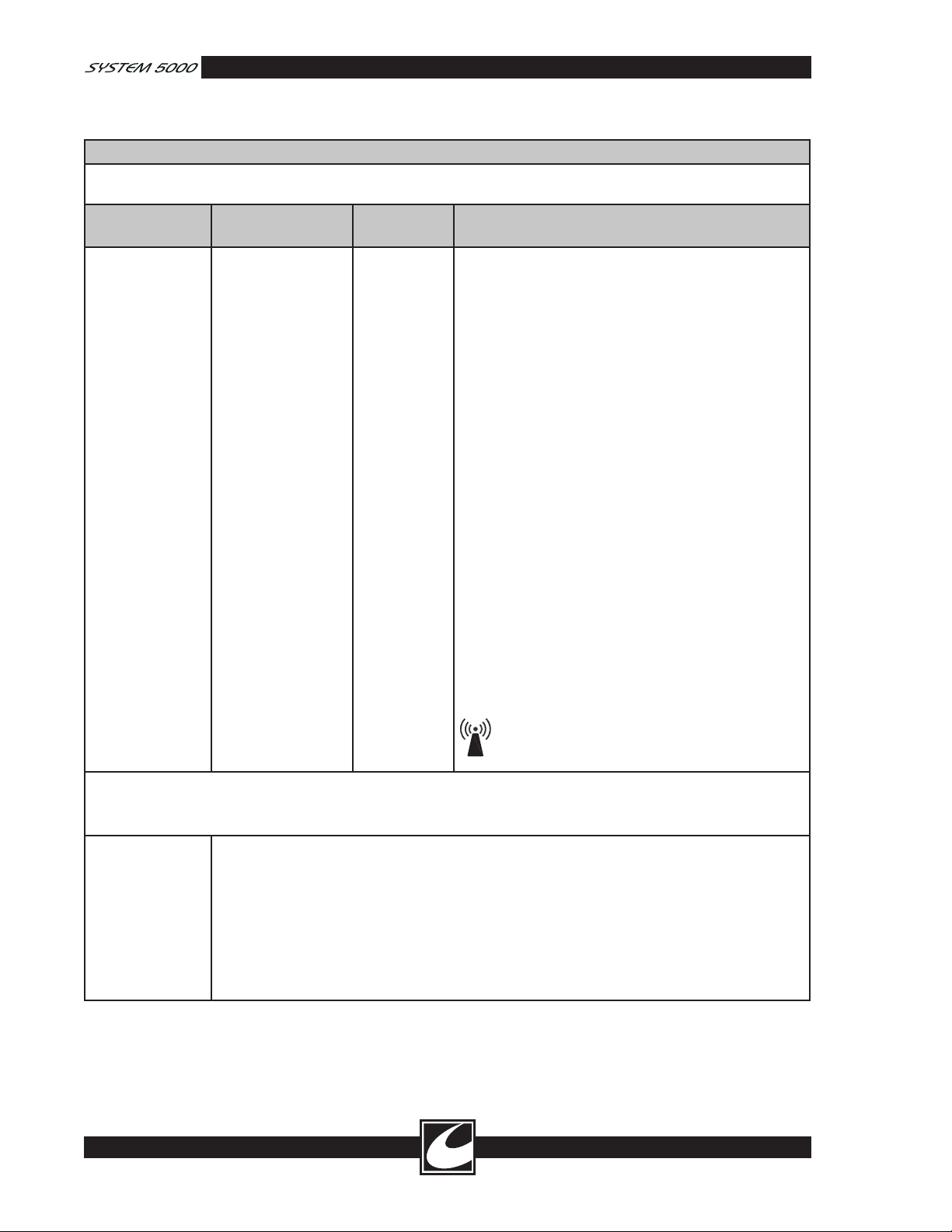
1.1.5.3 EN/IEC 60601-1-2 Table 204
Guidance and Manufacturer’s Declaration – Electromagnetic Immunity
The System 5000™ Electrosurgical Unit is intended for use in the electromagnetic environment specified below. The
customer or the end user of the System 5000 Electrosurgical Unit should assure that it is used in such an environment.
Immunity Test IEC60601 test
level
Compliance
level
Electromagnetic environment - guidance
Portable and mobile RF communications equipment
should be used no closer to any part of the System
5000™ Electrosurgical Unit, including cables, than the
recommended separation distance calculated from the
equation applicable to the frequency of the transmitter.
Recommended separation distance
Conducted RF
IEC 61000-4-6
Radiated RF
IEC 61000-4-3
NOTE 1 At 80 MHz and 800 MHz, the higher frequency range applies.
NOTE 2 These guidelines may not apply in all situations. Electromagnetic propagation is affected by absorption and
reflection from structures, objects and people.
a
b
3 Vrms
150 kHz to 80 MHz
3 V/m
80 MHz to 2.5 GHz
Field strengths from fixed transmitters, such as base stations for radio (cellular/cordless) tele
phones and land mobile radios, amateur radio, AM and FM radio broadcast and TV broadcast
cannot be predicted theoretically with accuracy. To assess the electromagnetic environment due
to fixed RF transmitters, an electromagnetic site survey should be considered. If the measured
field strength in the location in which the System 5000™ Electrosurgical Unit is used exceeds the
applicable RF compliance level above, the System 5000™ Electrosurgical Unit should be observed
to verify normal operation. If abnormal performance is observed, additional measures may be
necessary, such as reorienting or relocating the System 5000™ Electrosurgical Unit.
Over the frequency range 150 kHz to 80 MHz, field strengths should be less than [v1] V/m.
3 Vrms
3 V/m
d = 1.2√P
d = 1.2√P 80 MHz to 800 MHz
d = 2.3√P 800 MHz to 2.5 GHz
where P is the maximum output power rating of the
transmitter in watts (W) according to the transmitter
manufacturer and
tance in meters (m).
Field strengths from fixed RF transmitters, as determined
by an electromagnetic site survey,
compliance level in each frequency range.
Interference may occur in the vicinity of equipment
marked with the following symbol:
d is the recommended separation dis-
a
should be less than the
b
-
1-8
Page 13
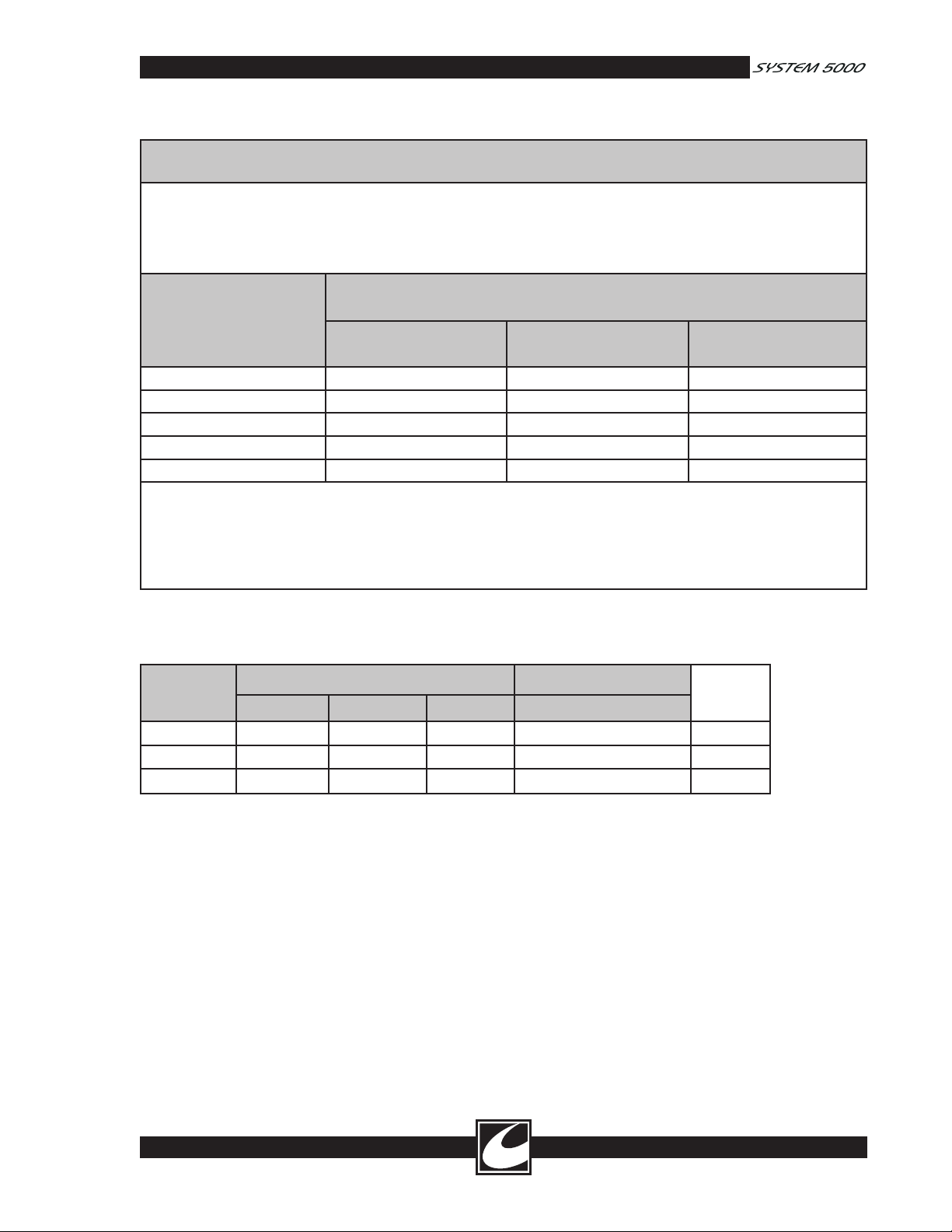
1.1.5.4 EN/IEC 60601-1-2 Table 206
Recommended separation distances between portable and mobile RF communications equipment
and the System 5000™ Electrosurgical Unit
The System 5000™ Electrosurgical Unit is intended for use in an electromagnetic environment in which radiated RF
disturbances are controlled. The customer or the user of the System 5000™ Electrosurgical Unit can help prevent elec
tromagnetic interference by maintaining a minimum distance between portable and mobile RF communications equip
ment (transmitters) and the System 5000™ Electrosurgical Unit as recommended below, according to the maximum
output power of the communications equipment.
Rated maximum output
power of transmitter
150 kHz to 80 MHz
(W)
0.01 0.12 0.12 0.23
0.1 0.38 0.38 0.73
1 1.2 1.2 2.3
10 3.8 3.8 7.3
100 12 12 23
For transmitters rated at a maximum output power not listed above, the recommended separation distance
(m) can be estimated using the equation applicable to the frequency of the transmitter, where P is the maximum output
rating of the transmitter in watts (W) according to the transmitter manufacturer.
NOTE 1 At 80 MHz and 800 MHz, the separation distance for the higher frequency range applies.
NOTE 2 These guidelines may not apply in all situations. Electromagnetic propagation is affected by absorption and
reflection from structures, objects and people.
Separation distance according to frequency of transmitter
(m)
d = 1.2√P
80 MHz to 800 MHz
d = 1.2√P
800 MHz to 2.5 GHz
d = 2.3√P
d in meters
-
-
1.2 Specifications
Input Power: 600 watts maximum
Frequency
Hz
50-60 115 104 127 5.3 T6.3A
50-60 100 90 110 6.2 T8.0A
50-60 230 198 253 2.7 T3.15A
*Fuses are Type T, High Breaking
1.2.1 Mains Overcurrent Protection
Two fuses for each ESU with ratings as noted in the table above.
1.2.2 Mains Frequency Leakage
Designed to comply with IEC60601-1: 1995.
Patient connections to Neutral: Less than 10 µA.
Chassis to Neutral: Less than 25 µA (120V), Less than 45 µA (240V).
Mains Voltage VRMS Mains Current ARMS
Fuses*
Nominal Minimum Maximum Maximum
1-9
Page 14

1.2.3 Regulatory Compliance
Designed to comply with Medical Electrical Equipment Standards (UL2601-1: 2000, IEC60601-1: 1995,
IEC60601-1-1: 2000, IEC60601-1-2: 2001, IEC60601-1-4: 2000, IEC60601-2-2: 1998,
HF18: 2001).
Manufactured in an ISO 13485: 2003 Registered Facility.
Type of protection against electric shock: IEC Class 1.
Degree of protection against electric shock: Type CF, Defibrillator Proof.
Non-Ionizing Radiation.
1.2.4 Operation
Mode of operation: Intermittent 10 Sec on/30 Sec off.
1.2.5 Power Display Accuracy
The greater of ±10% of display or ±3 watts at rated load.
1.2.6 Line Regulation
Power Change <1%/V for the range of line voltages specified.
1.2.7 Environmental
Operating Conditions: 10°C to 30°C, 95% RH Non-condensing maximum.
Degree of protection against Ingress of Water: IPX1 (Protection against vertically falling water drops).
Mounting Restriction: 2-inch (5cm) clearance required on each side, back and above the ESU for cooling.
Cooling: Natural convection, conduction, radiation and temperature controlled fan.
Storage Conditions: -40°C to 70°C, at altitudes from –60 to +4500 meters above mean sea level when sealed
in original poly bag, packing material and shipping carton.
Prior to shipment or storage, the ESU should be enclosed and sealed in a polyethylene bag and placed in
original carton using original packaging materials.
RF Leakage: <100 mA per IEC60601-2-2: 1998, Clause 19.3.101b.
ANSI/AAMI
1.2.8 Contact Quality Monitor
Single dispersive electrode: Two wire continuity detector, typical trip threshold is 10 ohms
Dual dispersive electrode: Two wire resistance monitor, typical acceptance range 10 to 150 ohms, trip thresh
old typically 30% higher than initial activation, visual indication of patient resistance changes.
1.2.9 Audio Specifications
Cut = 520 Hz
Coag = 440 Hz
Bipolar = 440 Hz
Acc Fault = 847 Hz (pulsating)
Dispersive Electrode Alarm = 847 Hz (pulsating)
Err Fault = 847 Hz (pulsating)
Increase Power Level = 379 Hz
Decrease Power Level = 343 Hz
(All tones are 45 dbA minimum except Alarms, which are 65 dbA minimum)
Enter Cut Remote Power Control = 440 Hz fol
lowed by 574 Hz
Enter Coag Remote Power Control = 440 Hz
followed by 515 Hz
Bipolar Output Tone = 215 Hz
Pulse Cut Activation Tone = 520 Hz with peri
odic short pulses at 481 Hz during output power
pulses
Pulse Coag Activation Tone = 440 Hz with peri
odic short pulses at 384 Hz
-
-
-
-
1-10
Page 15
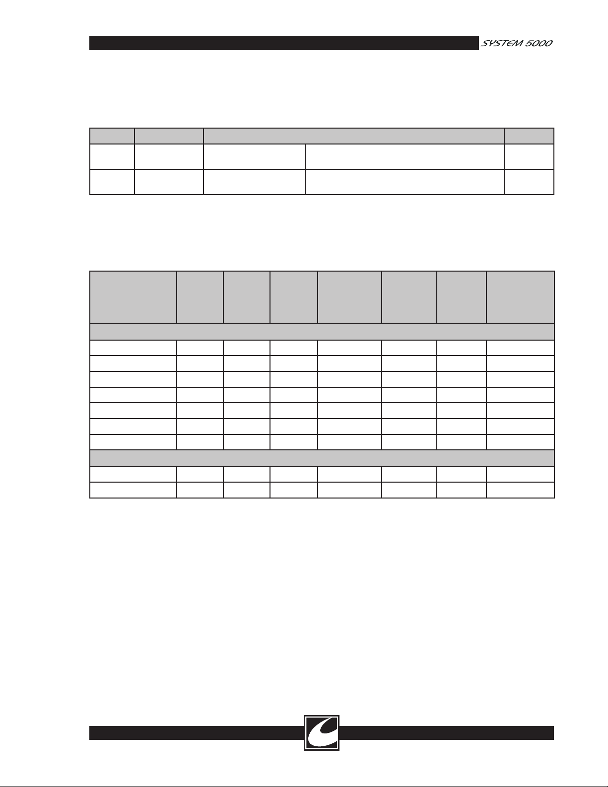
1.2.10 Other Specifications
Power Cord: All units supplied with an IEC-320 250V 10A 65°C mains inlet connector. Power cords can
be ordered from CONMED Electrosurgery or obtained from other sources if the following specifications are
met:
Region Specification Description Standard
USA,
Canada
Europe Any HAR cord
Any UL, CSA
manufacturer
manufacturer
SJT or better 250VAC, minimum 16AWG, 3 Conductor, maxi
mum length 20 feet (6m)
<HAR>H05WF3G1.0 Copper 1.0mm2 minimum cross sectional area,
maximum length 20 feet or 6.0m
-
UL817
IEC60799
Weight: 21.5 lb. (9.75 Kg)
Height: 5.5 inches (14 cm); Width: 13.5 inches (35 cm); Depth: 21.5 inches (48 cm) including handle
SPECIFICATIONS SUBJECT TO CHANGE WITHOUT NOTICE
1.2.11 Operating Modes and Nominal Output Parameters
Mode Max
Power
(watts)
Rated
Load
(ohms)
Typical
Crest
Factor
Max Open
Circuit
Voltage
(Peak)
Max
Loaded
Voltage
(Peak)
Carrier
Freq.
(KHz)*
Pulse
Repetition
Freq. (KHz)
Monopolar
Pure Cut 300 500 1.4 - 1.7 800 820 391 N/A
Blend 1
Blend 2
Blend 3
Pinpoint Coag
Standard Coag
Spray Coag
200 500 1.5 – 1.9 860 930 391 20.0
200 500 1.8 – 2.4 1100 1100 391 20.0
200 500 2.4 – 2.9 1480 1480 391 20.0
120 500 3.7 - 4.6 2120 2120 391 20.0
120 500 5.6 – 6.6 3140 3500 562 39.0
80 500 7.1 – 9.7 6350 6350 562 19.5
Bipolar
Micro Coag 50 50 1.5 – 1.9 170 180 391 N/A
Macro Coag
90 300 1.6 - 2.0 610 610 391 N/A
*Measured in the open circuit condition.
•Activation of Pulse Cut will make the selected cut mode, Pure Cut, Blend 1, Blend 2, or Blend 3 active for
70 milliseconds every 600 milliseconds.
•Activation of Pulse Coag will make the selected coag mode, either Standard or Spray, active for 2.5 mil
liseconds every 5 milliseconds. Displayed power setting will represent the average power being delivered
which is approximately half the power delivered during the pulses.
•LAP Specialty Mode output parameters match general operation parameters except the maximum voltage
is limited to less than 2700 Volts peak.
•FLUIDS Specialty Mode output parameters match general operation parameters with an initial energy
boost upon activation to initiate an arc.
-
1-11
Page 16

1.3 Explanation of Symbols
1.3.1 Control Panel
Note: International System 5000™ units use
symbols on the Control Panel. Some symbols are
replaced by words on the domestic (U.S.) units.
These words are indicated by bold text in the sym
bol description.
Pure Cut waveform with minimum ther-
mal damage and hemostasis.
Remote Power Control Key:
Press to enable or disable Remote
Power Control.
Program
-
Program Store Key
Blend 1 waveform with moderate
hemostasis.
Blend 2 waveform with medium
hemostasis.
Blend 3 waveform with maximum
hemostasis.
Pinpoint Monopolar Coagulation.
Standard Monopolar Coagulation.
Spray Monopolar Coagulation.
Micro Bipolar Coagulation
Macro Bipolar Coagulation
General Setup
Selection Scroll Button
1.3.2 Interior
Protective Earth (Inlet
Connector)
High Voltage Circuitry
1.3.3 Output/Control Panel
Dispersive Electrode –
Connection for monopolar dis
persive electrode.
ReadiPlug™ Universal Accessory
Receptacle
Hand-controlled Monopolar
Output: Connection for handcontrolled monopolar accessories.
-
1-12
Fluids Specialty Mode
Lap Specialty Mode
Single Dispersive electrode
Status/Alarm Indicator for single
monopolar dispersive electrodes.
Dual Dispersive electrode
Status/Alarm Indicator for dual
monopolar dispersive electrodes.
Bipolar Output
Current Indicator
Pulse Mode
Bipolar Output: Connection for
bipolar accessories.
Caution: High voltage output.
Type CF: Patient connections are iso-
lated from earth and resist the effects
of defibrillator discharge.
RF Isolated: Patient connections are
isolated from earth at high frequency.
Consult accompanying documents
prior to placing equipment in service.
Page 17
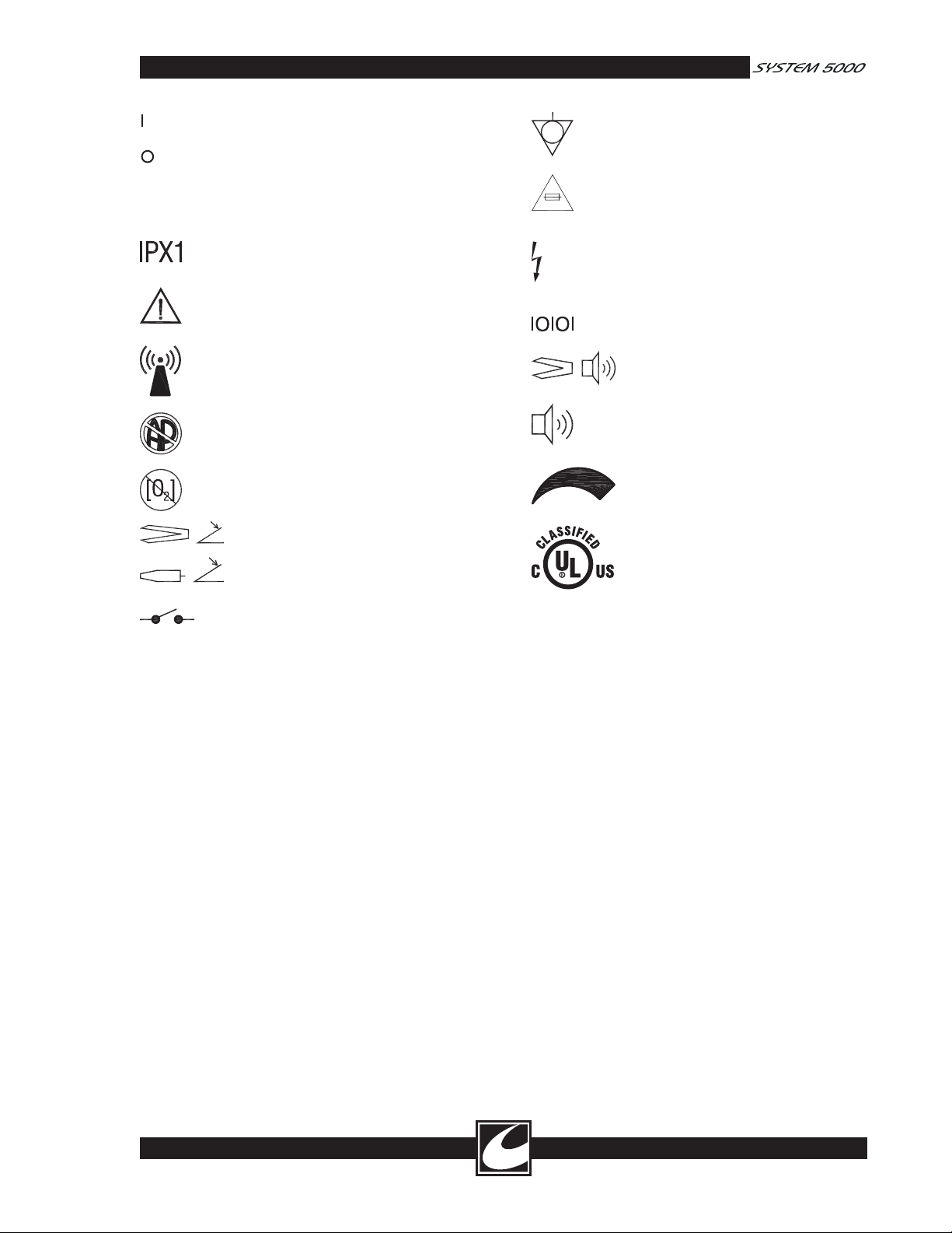
Power on: connected to the mains.
Power off: disconnected from the
mains.
1.3.4 Rear Panel
Equipotential Ground Terminal.
Replace fuse only with type and rat-
ing as shown.
Enclosure resists entry of vertically
falling water.
Consult accompanying documents
prior to placing equipment in service.
This equipment intentionally supplies
non-ionizing RF energy for physi
ological effect.
Explosion risk if used in the presence
of flammable anesthetics.
Do not operate in oxygen enriched
environments.
Bipolar Footswitch Connector.
Monopolar Footswitch
Connector.
Activation relay connector.
-
Caution - High Voltage Inside -
Refer servicing to qualified person
nel.
Serial Interface Connector.
Volume control: Bipolar Activation
tone.
Volume control: Activation tone.
Volume increase/decrease.
Medical Electrical Equipment:
With respect to electric shock, fire
and mechanical hazards only in
accordance with UL2601-1/CAN/
CSA C22.2 NO. 601.1 380X
-
1-13
Page 18
0
1000
2000
3000
4000
5000
0 100 200 300
1.4 Output Characteristic Curves
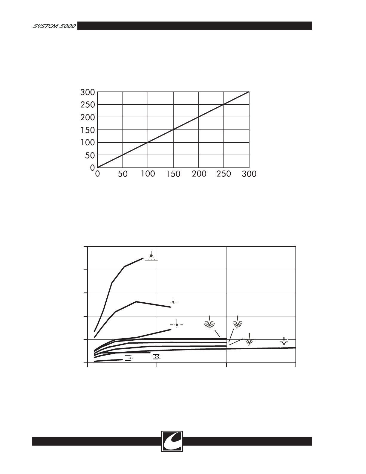
Figure 1.1 illustrates output power delivered to rated load for all available modes. Figure 1.2 illustrates the
maximum peak voltage available at a given power setting and output mode. Section 1.2 specifies rated loads
and maximum power for each mode, while figures 1.3 – 1.11 illustrate output power delivered to a range of
load resistances for each mode.
Power Output (Watts to Rated Load)
Displayed Setting
Figure 1.1 Output Power vs. Power Setting
1-14
Output Voltage (Peak)
Power Setting
Figure 1.2 Display vs. Open Circuit Peak Voltage
Page 19
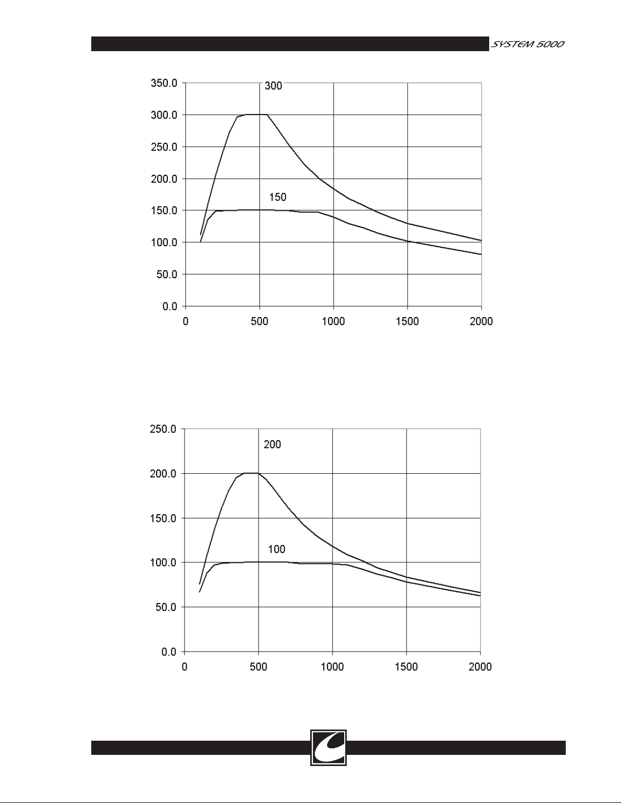
Output Power (Watts)
Load Resistance (Ohms)
Figure 1.3 Load Regulation, Monopolar Pure Cut
Output Power (Watts)
Load Resistance (Ohms)
Figure 1.4 Load Regulation, Monopolar Blend 1
1-15
Page 20
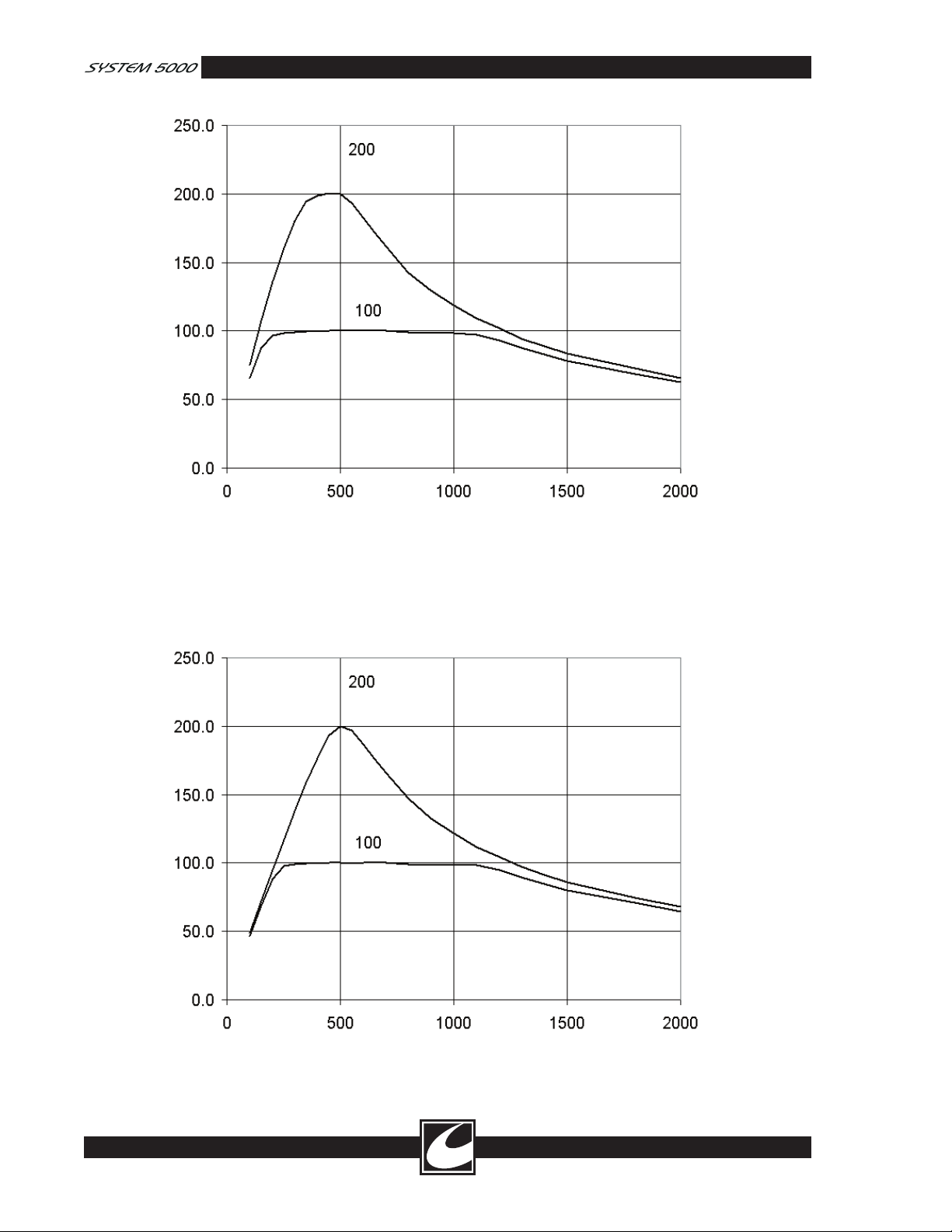
Output Power (Watts)
Load Resistance (Ohms)
Figure 1.5 Load Regulation, Monopolar Blend 2
1-16
Output Power (Watts)
Load Resistance (Ohms)
Figure 1.6 Load Regulation, Monopolar Blend 3
Page 21
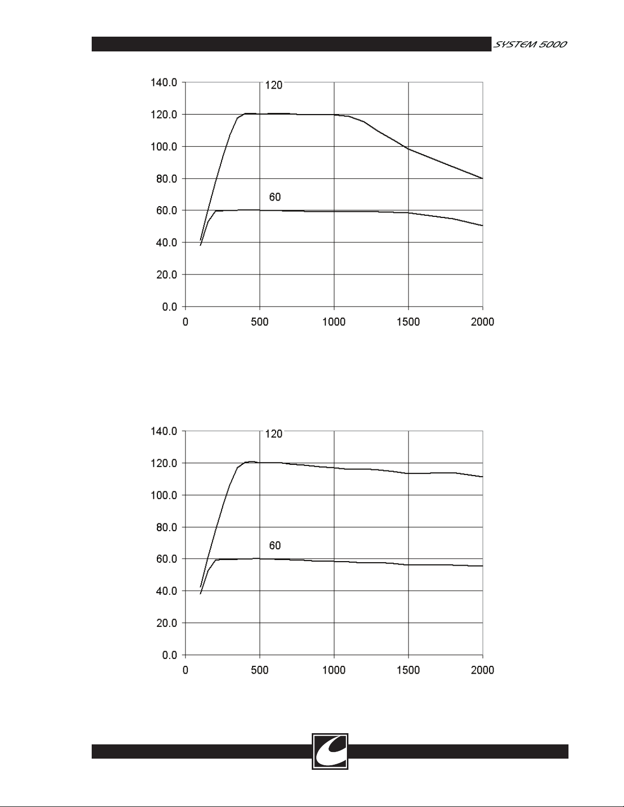
Output Power (Watts)
Load Resistance (Ohms)
Figure 1.7 Load Regulation, Monopolar Pinpoint Coag
Output Power (Watts)
Load Resistance (Ohms)
Figure 1.8 Load Regulation, Monopolar Standard Coag
1-17
Page 22
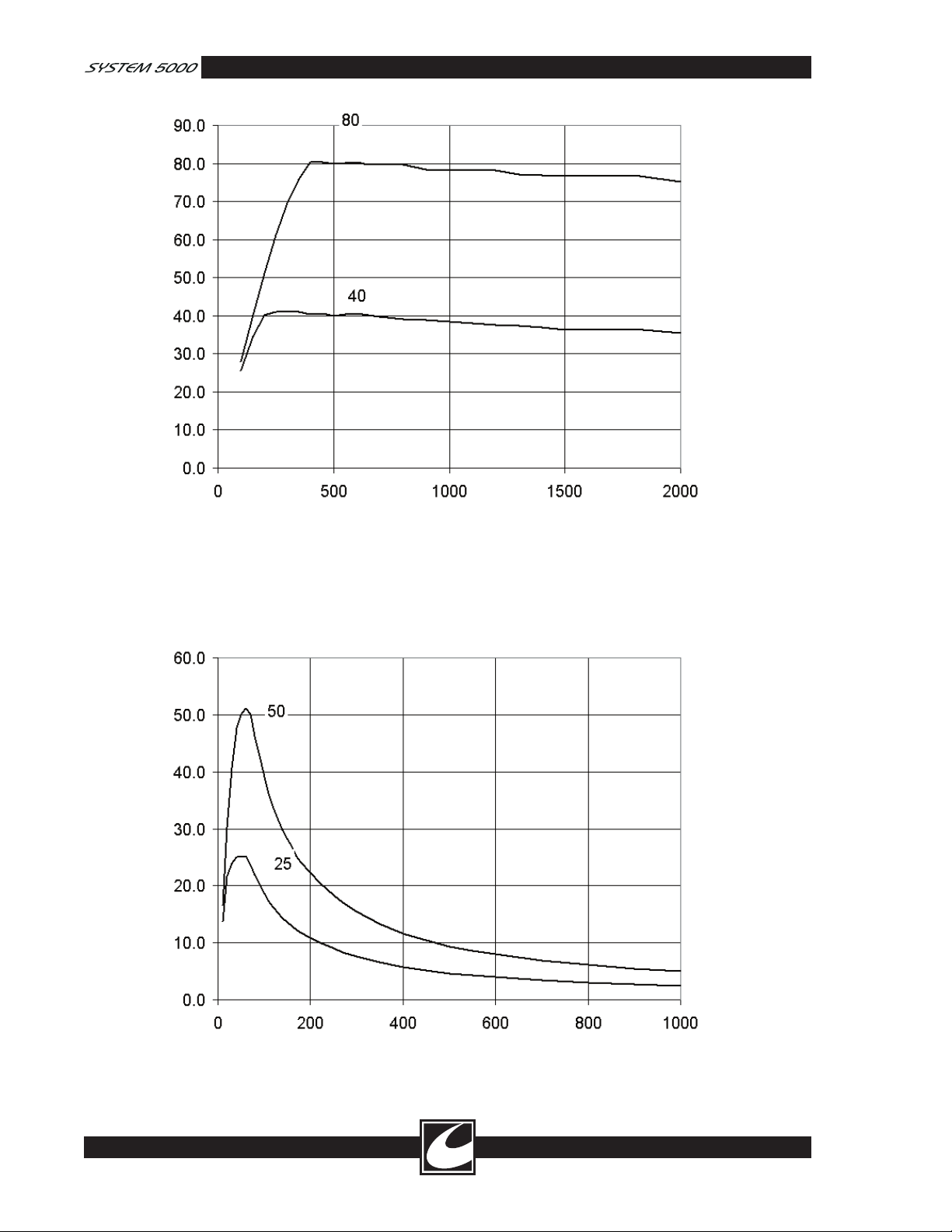
Output Power (Watts)
Load Resistance (Ohms)
Figure 1.9 Load Regulation, Monopolar Spray Coag
1-18
Output Power (Watts)
Load Resistance (Ohms)
Figure 1.10 Load Regulation, Bipolar Micro
Page 23
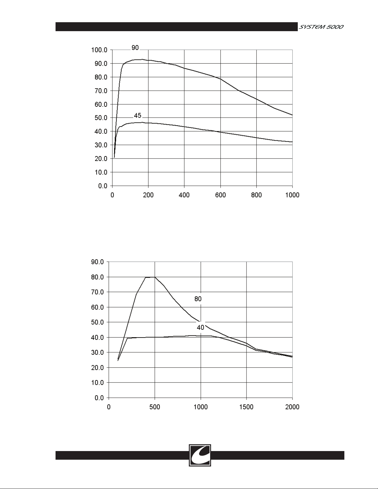
Output Power (Watts)
Load Resistance (Ohms)
Figure 1.11 Load Regulation, Bipolar Macro
Output Power (Watts)
Load Resistance (Ohms)
Figure 1.12 Load Regulation, Lap Spray
1-19
Page 24
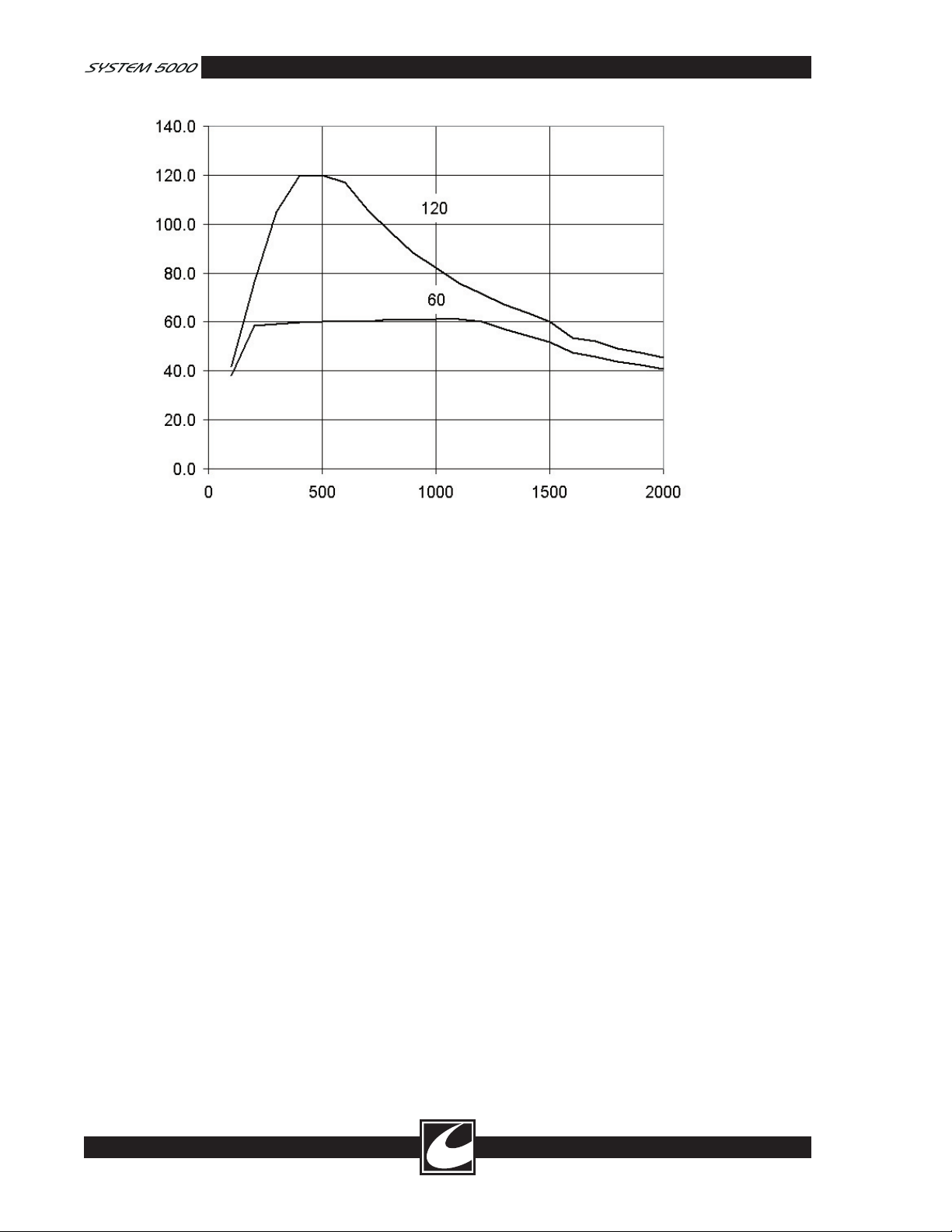
Output Power (Watts)
Load Resistance (Ohms)
Figure 1.13 Load Regulation, Lap Standard
1-20
Page 25
TM
Installation and Operation
Section 2.0
This section contains initial installation, preliminary checks and operating instructions for the
System 5000™.
2.1 Initial Inspection
Unpack the ESU upon receipt and physically
inspect it for any obvious damage that may have
occurred during shipment. A Hospital Qualified
Biomedical Technician should perform this inspec
tion. Notify the carrier and your CONMED rep
resentative immediately if damage is found.
-
2.2 Installation
The ESU may be mounted on a matching mobile
pedestal or any stable mobile pedestal or table.
2.2.1 Installation Of Fuses
Outside of the U.S., proper fuses must be installed
prior to connection to any power source. Install
fuses in the following manner:
a) Ensure the power cord is disconnected from
the ESU.
b) Locate the fuses that are packaged with the
ESU. There will be three sets of fuses pro
vided:
• 8.0 A for installations with nominal
mains voltages of 100 VRMS (Part num
ber 62-4236-800).
• 6.3 A for installations with nominal
mains voltages of 115 VRMS (Part number 62-4236-630).
• 3.15 A for installation with nominal
mains voltages of 230 VRMS or greater
(Part number 62-4236-315).
Choose the correct fuses for the mains voltage in
the location where the ESU will be used.
c) Use a flat blade screwdriver to remove
the covers from each of the two FUSE
RECEPTACLES by turning the covers
approximately ¼ turn to the left.
d) Insert one of the chosen fuses in each of the
two FUSE RECEPTACLE covers.
-
-
e) Re-insert the two FUSE RECEPTACLE
covers, with fuses installed, into the FUSE
RECEPTACLES.
f) Use a flat blade screwdriver to gently push
each of the two covers into the FUSE
RECEPTACLES and rotate each one approxi
mately ¼ turn to the right to lock them in
place.
g) Connect the power cord to the back of the
ESU. Installation of the ESU may now be
completed.
WARNING
THE POWER CORD OF THE ESU
SHOULD BE CONNECTED TO
A PROPERLY POLARIZED AND
GROUNDED POWER SOURCE
WHOSE VOLTAGE AND FREQUENCY
CHARACTERISTICS ARE COMPATIBLE
WITH THOSE LISTED ON THE
NAMEPLATE OF THIS ESU.
CAUTION: Since the ESU depends on both
natural convection and forced air for cooling,
it should not be installed in a cabinet or similar
enclosure. If mounted on a shelf or otherwise
near a wall, allow a two-inch clearance around and
above the ESU to permit free circulation of air
along the sides of the ESU.
-
2.3 Preliminary Checks
Prior to initial installation and use of this ESU,
performance of the device should be tested in
accordance with this manual. Results of that test
ing should be compared to the results tabulated
on the factory Test Data Sheet supplied with each
ESU. This data should be retained for future ref
erence and comparison.
2.3.1 Preliminary Functional Testing
The following checks are recommended upon ini
tial installation of the equipment and prior to each
use of the instrument to avoid unnecessary delays
in surgery. See Figure 2.1 for location of controls
and connectors.
-
-
-
2-1
Page 26

1. Ensure the power switch is OFF and no
accessories are connected.
2. Connect the power cable to a properly
grounded and polarized mating power recep
tacle of the proper voltage and frequency.
3. Connect a CONMED dual-treadle monopolar
footswitch and a single treadle CONMED
bipolar footswitch to their mating connec
tors at the rear of the ESU. Note: Use only
CONMED Electrosurgery footswitches.
Although other types may fit, they may not
be functionally compatible.
4. Make no connection to the dispersive elec
trode receptacle at this time.
5. Set the Power Switch to the ON (“|”) posi
tion. As the ESU goes through the internal
self-diagnostics, it should respond by:
a) Sounding a series of test tones.
b) During the test tone, displaying a total of
nine “8’s” on the four digital displays.
c) Illuminating all three activation indica
tors, all eight key indicators, two disper
sive electrode indicators and the entire
dual dispersive electrode contact quality
BARGRAPH.
d) After the display test, the ESU will show
the software revision level in the COAG
display window. The ESU is conducting
a power-on self-test during this interval.
e) If there are no errors, normal operational
parameters will then be displayed.
6. Depress the Cut treadle of the monopolar
footswitch. The dispersive electrode alarm
should sound and dispersive electrode indica
tors should flash alternating red. While hold
ing the Cut treadle, rotate the volume control
over its full range and verify there is no sig
nificant change in sound level. Release the
Cut footswitch and the tone should stop.
7. Select each of the modes by pressing the
Mode Scroll Keys and note the displayed
power settings for each mode in the corre
sponding displays.
8. Verify that the Pure Cut Mode can be selected
and adjusted up and down by:
• Pressing the Cut Mode Scroll Key until
the Pure Cut Activation indicator is illu
minated.
-
-
-
-
-
-
-
-
-
-
-
• Pressing the Monopolar Cut Power
Adjustment Keys to increase and decrease
the setting while verifying that the display
changes appropriately and verifying that
no other displays change.
• Pressing the Cut Mode Scroll Key and
verifying that the settings for each of the
other modes were not changed by chang
ing the Pure Cut Mode power setting.
9. Verify that each of the other modes can be
selected and adjusted up and down in the
same manner as the Pure Cut Mode described
above. The other modes include:
• Blend 1
• Blend 2
• Blend 3
• Pinpoint Coag
• Standard Coag
• Spray Coag
• Bipolar Micro
• Bipolar Macro
• Pulse Cut
• Pulse Coag
• FLUIDS Specialty Mode
• LAP Specialty Mode
Return all settings to the desired setting.
10. Select each of the specialty modes by press
ing the Specialty Mode Scroll Key and verify
ing that the selected specialty mode scrolls
through General, Fluids, and Lap. Verify
that the displayed power settings for each
specialty mode can be changed independently
of the other modes by adjusting the cut, coag,
or bipolar power. Return all settings to the
desired setting and return the specialty mode
to General before proceeding.
11. Depress the bipolar footswitch. Confirm
that the Bipolar Activation indicator illumi
nates and a bipolar activation tone is sounded.
While continuing to depress the bipolar
footswitch, rotate the Volume Control over
its full range to verify the function of that
control and that sound is audible at all posi
tions. This control may be left at any desired
position. Release the bipolar footswitch and
confirm the System 5000™ returns to its idle
state. Set the bipolar power setting to 1 watt
and verify the bipolar hand control is func
-
-
-
-
-
-
2-2
Page 27

tional by use of the appropriate forceps or by
connecting a jumper between the center and
right hand Bipolar Output receptacle on the
Output Panel. The effect will be identical to
depressing the bipolar footswitch.
12. Verify that the Single and Dual Dispersive
Electrode Status / Alarm Indicators alternately
flash red. Connect a single dispersive elec
trode to the Dispersive Electrode Receptacle.
Confirm the Single Dispersive Electrode
Status / Alarm Indicator is steady green.
13. Depress the Cut treadle of the Monopolar
footswitch. The yellow Cut Activation indica
tor should light and the cut activation tone
should sound.
14. While continuing to press the Cut treadle
of the footswitch, press the Coag treadle.
The yellow Cut Activation indicator should
remain illuminated and the Cut activation
tones should continue. Release the Cut
treadle while continuing to press the Coag
treadle and confirm that the yellow Cut
Activation indicator extinguishes, the blue
Coag Activation indicator illuminates and
the activation tone changes from Cut to
Coag. Release the coag treadle and verify
that the display returns to normal. Press the
Coag treadle and verify that the blue Coag
Activation indicator illuminates until the Coag
treadle is released.
15. Connect a hand-controlled accessory to one
of the Monopolar Accessory Receptacles.
Activate the Cut and Coag buttons on the
accessory, one at a time, verifying that each
control causes the correct indicator and tone
to sound. Move the hand-controlled acces
sory to the other Monopolar Accessory
Receptacle and repeat.
16. Disconnect the single dispersive electrode and confirm that the System 5000™
beeps three times and the Single and Dual
Dispersive Electrode Status / Alarm Indicators
alternately flash red.
2.3.2 Preliminary Performance Testing
After the ESU passes the Preliminary Functional
Tests of Section 2.3.1, preliminary performance
testing may be conducted. Such testing is best
carried out by use of an electrosurgical generator
tester. Use a non-inductive resistor with the same
value as the rated generator output impedance for
-
-
the best accuracy of the tester. (See Specifications,
Section 1.2).
If no tester is convenient, the availability of thera
peutic current may be ascertained subjectively by
attempting to cut and coagulate on surrogate tis
sue such as a piece of meat or fresh fruit, a wet
bar of soap or a sponge moistened with saline.
-
-
2.4 Controls, Displays and Connectors
The numbers preceding the following paragraphs
correspond to the numbered items in Figures 2.1,
2.2 and 2.3.
-
2.4.1 Control Panel
All controls, except for the volume controls, are
located on the front control panel. Figure 2.1
illustrates the Universal Symbols control panel.
Your control panel may be in English.
1. DUAL DISPERSIVE ELECTRODE
STATUS / ALARM INDICATOR: Indicates
the status of a dual dispersive electrode when
the dual dispersive electrode is connected
to the ESU. This indicator is made up of a
STATUS INDICATOR and a BARGRAPH,
which indicates the relative quality of the dual
dispersive electrode application.
The STATUS INDICATOR will flash red
prior to connection of any dispersive electrode
or connection of a dual dispersive electrode
that is not applied to the patient. This indi
cator will flash green after a dual dispersive
electrode is applied to the patient and the
contact quality of the dual dispersive electrode
is at an acceptable level. The status indicator
will illuminate steady green upon first activa
tion using a hand control or footswitch with
a dual dispersive electrode that is installed and
connected with acceptable contact quality.
Prior to activation, the BARGRAPH will
show a relative measure of the contact qual
ity between the two elements of the dual
dispersive electrode. Good contact quality is
indicated by illumination of many segments,
while poor contact quality will illuminate
fewer segments. Acceptable contact quality to
enable safe use of the ESU will be indicated
by illumination of one or more segments.
All of the BARGRAPH segments will be
illuminated upon activation with an accept
ably installed and connected dispersive elec
trode. Fewer segments of the bar graph will
-
-
-
-
-
2-3
Page 28
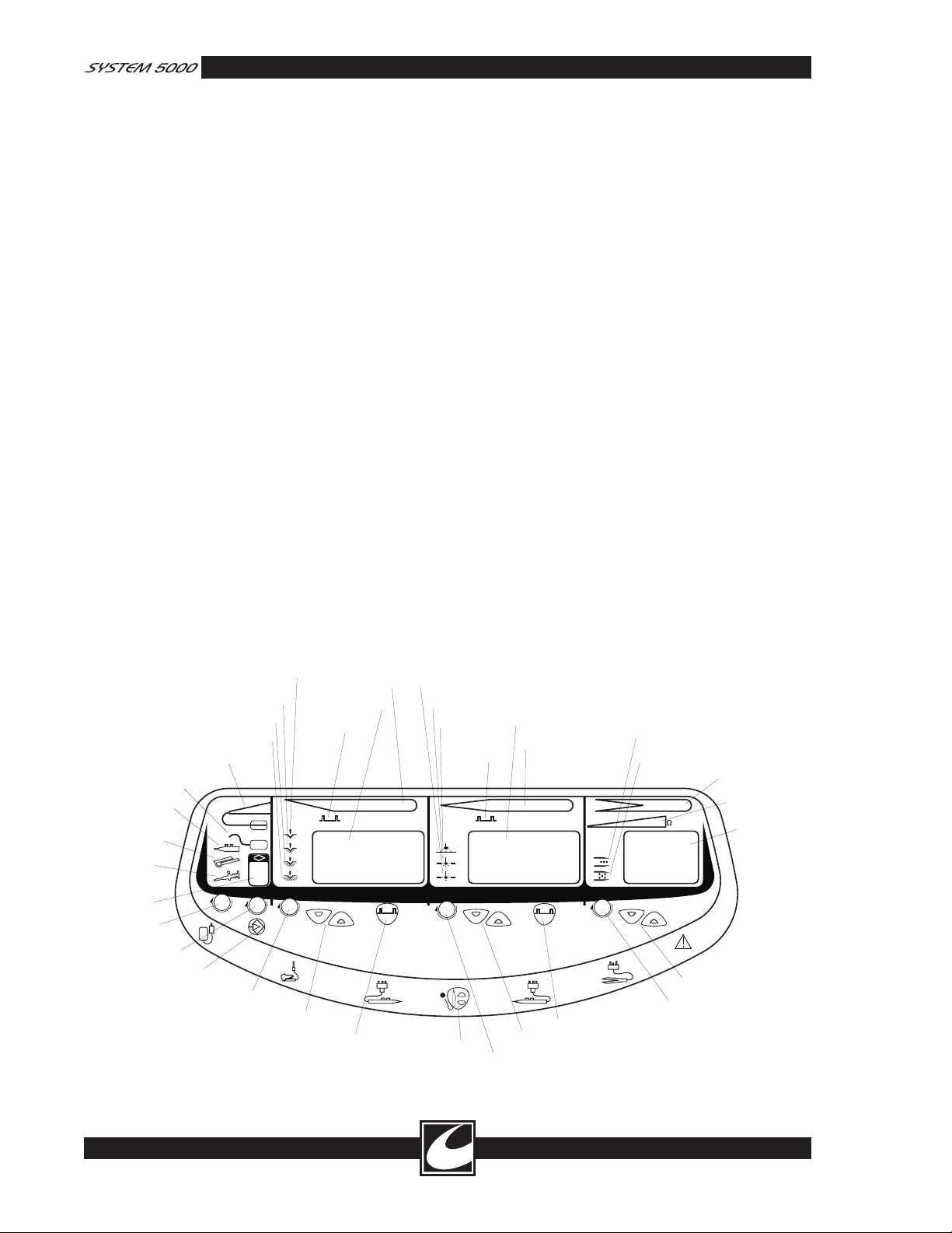
be illuminated as the contact quality of the
SYSTEM 5000
CUT COAG BIPOLAR
TM
2. SINGLE DISPERSIVE ELECTRODE
STATUS/ALARM INDICATOR
1. DUAL DISPERSIVE ELECTRODE
STATUS/ALARM INDICATOR
3. GENERAL MODE
INDICATOR
4. FLUIDS SPECIALTY
MODE INDICATOR
5. LAP SPECIALTY
MODE INDICATOR
6. PROGRAM
INDICATOR
7. SPECIALTY MODE
SCROLL KEY
8. PROGRAM SELECT
SCROLL KEY
9. PROGRAM
STORE KEY
10. PURE CUT MODE
INDICATOR
11. BLEND 1
INDICATOR
12. BLEND 2
INDICATOR
13. BLEND 3
INDICATOR
14. PULSE CUT
INDICATOR
15. MONOPOLAR CUT
POWER DIGITAL DISPLAY
16. MONOPOLAR CUT
ACTIVATION INDICATOR
17. CUT MODE
SCROLL KEY
18. MONOPOLAR CUT
POWER ADJUSTMENT KEYS
19. PULSE CUT KEY
22. SPRAY COAG
INDICATOR
21. STANDARD COAG
INDICATOR
20. PINPOINT COAG
INDICATOR
23. PULSE COAG
INDICATOR
24. MONOPOLAR COAG
POWER DIGITAL DISPLAY
25. MONOPOLAR COAG
ACTIVATION INDICATOR
26. COAG SCROLL KEY
27. MONOPOLAR COAG
POWER ADJUSTMENT KEYS
28. PULSE COAG KEY
29. MICRO BIPOLAR
INDICATOR
30. MACRO BIPOLAR
INDICATOR
32. BIPOLAR OUTPUT
METER
31. BIPOLAR ACTIVATION
INDICATOR
33. BIPOLAR POWER
DIGITAL DISPLAY
34. BIPOLAR SCROLL KEY
35. BIPOLAR POWER
ADJUSTMENT KEYS
36. REMOTE POWER
CONTROL KEY
dispersive electrode deteriorates; as a result,
the Dual Dispersive Electrode Status / Alarm
Indicator gives a relative measure of contact
quality as the procedure progresses.
If the contact quality deteriorates to a level
that is unacceptable, all BARGRAPH seg
ments will be extinguished, the STATUS
INDICATOR will flash red and an alarm will
sound.
2. SINGLE DISPERSIVE ELECTRODE
STATUS / ALARM INDICATOR: Indicates
the status of a single dispersive electrode when
the single dispersive electrode is connected to
the ESU. This STATUS INDICATOR will
flash red prior to connection of any dispersive
electrode. This STATUS INDICATOR will
illuminate steady green after a single disper
sive electrode is acceptably connected to the
ESU.
WARNING
THE SINGLE DISPERSIVE ELECTRODE
STATUS / ALARM INDICATOR DOES
NOT PROVIDE ANY INDICATION OF
THE CONTACT QUALITY BETWEEN
THE SINGLE DISPERSIVE ELECTRODE
AND THE PATIENT.
If the quality of connection between the ESU
and the single dispersive electrode deteriorates
to a level that is unacceptable, this STATUS
INDICATOR will flash red and an alarm will
sound.
3. GENERAL MODE INDICATOR: This
default mode illuminates when no Specialty
modes are selected.
4. FLUIDS SPECIALTY MODE
INDICATOR: Illuminates when Fluids
Specialty Mode is selected.
5. LAP SPECIALTY MODE INDICATOR:
Illuminates when Lap Specialty Mode is
selected
6. PROGRAM INDICATOR: Indicates the
selected program.
7. SPECIALTY MODE SCROLL KEY:
Pressing this key will scroll between General
mode, Fluids mode and Lap mode.
8. PROGRAM SELECT SCROLL KEY:
Pressing this key will scroll between the stored
program locations.
9. PROGRAM STORE KEY: Stores the current
settings into the selected program location.
10. PURE CUT ACTIVATION INDICATOR
:
Illuminates when monopolar Pure Cut Mode
has been selected.
2-4
Figure 2.1 Control Panel
Page 29

11. BLEND 1 INDICATOR: Illuminates when
monopolar Blend 1 is selected.
12. BLEND 2 INDICATOR: Illuminates when
monopolar Blend 2 is selected.
13. BLEND 3 INDICATOR: Illuminates when
monopolar Blend 3 is selected.
14. PULSE CUT INDICATOR: Illuminates
when Pulse Cut is selected.
15. MONOPOLAR CUT POWER DIGITAL
DISPLAY: Indicates the power setting for the
currently selected monopolar cut mode.
16. MONOPOLAR CUT ACTIVATION
INDICATOR: This yellow indicator lights
when the ESU is activated in a monopolar cut
mode.
17. CUT MODE SCROLL KEY: Pressing this
key will scroll through the Cut Modes: Pure,
Blend 1, Blend 2 and Blend 3.
18. MONOPOLAR CUT POWER
ADJUSTMENT KEYS: Adjusts the output
power setting of the selected cut mode.
19. PULSE CUT KEY: Pressing this key will
select or deselect Pulse Cut.
20. PINPOINT COAG INDICATOR:
Illuminates when monopolar Pinpoint coagu
lation has been selected.
21. STANDARD COAG INDICATOR:
Illuminates when monopolar Standard coagu
lation has been selected.
22. SPRAY COAG INDICATOR: Illuminates
when monopolar Spray coagulation has been
selected.
23. PULSE COAG INDICATOR: Illuminates
when Pulse Coag is selected.
24. MONOPOLAR COAG POWER DIGITAL
DISPLAY: Indicates the power setting in the
currently selected monopolar coagulation
mode.
25. MONOPOLAR COAG ACTIVATION
INDICATOR: This blue indicator lights
when the ESU is activated in a monopolar
coagulation mode.
26. COAG SCROLL KEY: Pressing this key
will scroll through the Coag Modes: Pinpoint,
Standard and Spray.
27. MONOPOLAR COAG POWER
ADJUSTMENT KEYS: Adjusts the output
power setting of the selected coagulation
mode.
28. PULSE COAG KEY: Pressing this key will
select or deselect Pulse Coag.
29. MICRO BIPOLAR INDICATOR:
Illuminates when micro bipolar is selected.
30. MACRO BIPOLAR INDICATOR:
Illuminates when Macro Bipolar is selected.
31. BIPOLAR ACTIVATION INDICATOR: This
indicator lights when the ESU is activated in the
bipolar mode.
32. BIPOLAR OUTPUT METER: This bar
graph display provides a measure of the tissue
resistance.
33. BIPOLAR POWER DIGITAL DISPLAY:
Indicates the bipolar mode power level set via
the Bipolar Power Adjustment Keys.
34. BIPOLAR SCROLL KEY: Pressing this key
will scroll through the Bipolar Modes: Macro
and Micro.
35. BIPOLAR POWER ADJUSTMENT
KEYS: Adjusts the output power level of the
selected bipolar mode.
36. REMOTE POWER CONTROL KEY:
Pressing this key will select or deselect
Remote Power Control. REMOTE POWER
-
-
CONTROL INDICATOR: Illuminates when
Remote Power Control is selected.
2.4.2 Output Panel
The output panel contains the power switch and
the accessory receptacles. The receptacles are illu
minated to aid in the insertion of the connectors
in low light conditions. Refer to Figure 2.2.
37. DISPERSIVE ELECTRODE
RECEPTACLE: This receptacle accepts a
standard two-pin single or dual dispersive
electrode plug.
38. ReadiPlug™ UNIVERSAL ACCESSORY
RECEPTACLE: This receptacle accepts acces
sory cables equipped with standard active
(Bovie #12) plugs, standard 4mm banana
plugs or pin-tip style disposable connectors
without the necessity of special adapters.
• Banana plugs can be inserted and removed
directly without pushing the button.
• To insert a Bovie #12 plug, you must
push the button adjacent to the recep
tacle, insert the plug fully and release the
button. IMPORTANT: When removing
a Bovie #12 plug, you must press the
button while pulling the plug out.
-
-
-
2-5
Page 30
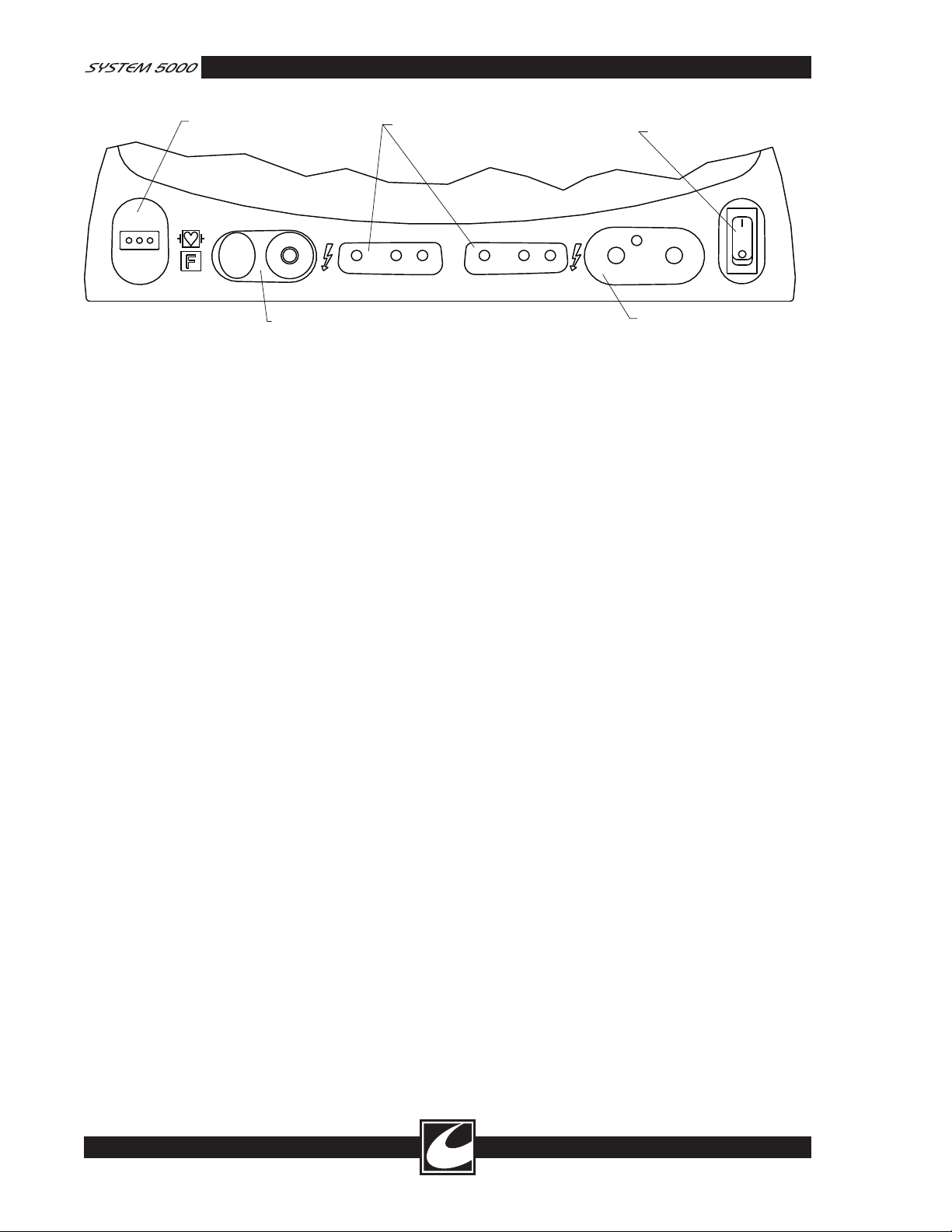
37. TWO-PIN DISPERSIVE
ELECTRODE RECEPTACLE
TM
38. ReadiPlug UNIVERSAL
ACCESSORY RECEPTACLE
39. HAND CONTROLLED MONOPOLAR
ACCESSORY RECEPTACLES
41. POWER SWITCH
40. BIPOLAR ACCESSORY
RECEPTACLE
Figure 2.2 Output Panel
• When handling the pin-tip style plug, hold
the wire about 3 inches (7.6 cm) from
the tip and push the button while insert
ing the tip. IMPORTANT: Verify proper
insertion by tugging gently on the plug to
ensure that the ReadiPlug™ mechanism
has properly retained the tip. To remove
the pin-tip, you must press the button
while pulling the plug out.
• This receptacle can only be activated by
the monopolar footswitch.
WARNING
NEVER CONNECT MORE THAN ONE
ACCESSORY AT A TIME TO
THIS
RECEPTACLE.
39. HAND-CONTROLLED MONOPOLAR
ACCESSORY RECEPTACLE: Two inde
pendent receptacles are provided for the con
nection of hand-controlled monopolar acces
sories. Only by the accessories connected to
them may activate these receptacles.
40. BIPOLAR ACCESSORY RECEPTACLE:
Bipolar output is activated by the bipolar
foot-controlled or by hand-controlled bipolar
accessories.
CONMED accessories with fixed
connection style plugs are recommended for
this receptacle. For legacy connections with
two banana plug leads, connect these active
bipolar forceps leads to the outside connec
-
tions.
41. POWER SWITCH: Primary power switch
for turning the ESU on and off.
2.4.3 Rear Panel
-
The rear panel contains the footswitch connectors,
power cord connector, fuses, volume controls and
a carrying handle. Refer to Figure 2.3.
42. CARRYING HANDLE
43. SPEAKER: Sound from the speaker ema
nates from this location.
-
44. NAMEPLATE: Specifies model number,
serial number, nominal line voltages, frequency, current and fuse rating information.
45. FAN: Forced air from the temperature-con
-
trolled fan is expelled in this location.
46. BIPOLAR FOOTSWITCH
CONNECTOR: A 3-pin threaded connector designed to accept any CONMED
Electrosurgery single-treadle bipolar
-
-
footswitch.
47. MONOPOLAR FOOTSWITCH
CONNECTOR: This 4-pin threaded con
nector is designed to accept plugs attached
to any dual treadle monopolar footswitch
available from CONMED Electrosurgery. Use
only CONMED Electrosurgery footswitches.
Other manufacturer’s footswitches may not be
compatible.
48. ACTIVATION RELAY CONNECTOR: A
receptacle for actuating smoke evacuators and
similar devices when delivering electrosurgical
output. The maximum contact rating for this
receptacle is 1 amp at 24 volts DC. Verify
that devices connected to this output func
tion properly in a manner that is synchronized
with ESU power delivery prior to use.
2-6
Page 31
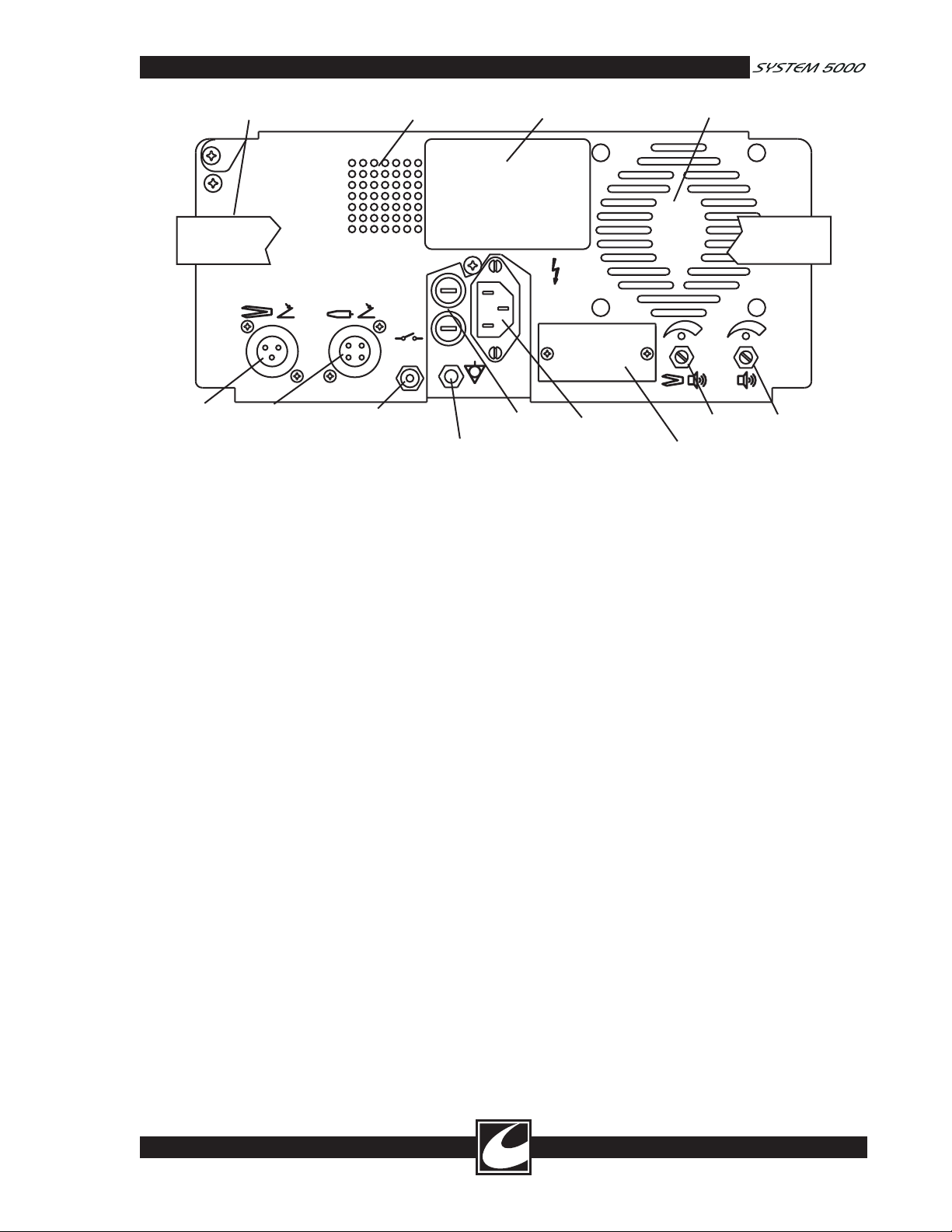
25V/1A
HOSPITAL
GRADE
IOIOI
MAX
ONLY
42. CARRYING HANDLE
43. SPEAKER
44. NAMEPLATE
45. FAN
46. BIPOLAR
FOOTSWITCH
CONNECTOR
47. MONOPOLAR
FOOTSWITCH
CONNECTOR
48. ACTIVATION
RELAY CONNECTOR
49. FUSE
RECEPTACLES
50. EQUIPOTENTIAL
GROUND CONNECTION
51. POWER INLET
52. SERIAL INTERFACE
CONNECTOR
54. VOLUME
CONTROL
53. BIPOLAR CURRENT
VOLUME CONTROL
Figure 2.3 Rear Panel
49. FUSE RECEPTACLES: For installation
50. EQUIPOTENTIAL GROUND
51. POWER INLET: Supplies AC mains power
52. SERIAL INTERFACE CONNECTOR:
53. BIPOLAR VOLUME CONTROL:
54. VOLUME CONTROL: Controls the vol
of two mains fuses with ratings as noted in
Section 2.2.1.
CONNECTION: Chassis ground connection
suitable for attachment of standard auxiliary
grounding cable when required for additional
protection against low frequency risk current.
to the ESU. It should only be connected to a
source of power corresponding to that listed
on the nameplate.
This connector provides a means of connec
tion with operating room control centers.
Only equipment approved by CONMED
should be connected to this interface.
Contact your CONMED Sales Representative
or CONMED Customer Service at the num
bers listed on the inside front cover of this
-
manual.
Controls the volume of the special tones pro
duced during bipolar electrosurgery. Rotation
to the right increases the volume. Does not
affect volume of alarm tones.
ume of the tones produced during normal
activation of the ESU. Rotation to the right
increases the volume. It does not affect the
volume of alarm tones.
2.5 Set Up For Use
1. Ensure the Power Switch is OFF, and then
connect the power cable to a properly
grounded and polarized mating power recep
tacle. Do not connect a dispersive electrode
at this time.
2. Inspect and connect the desired monopolar or
bipolar accessories to the connectors on the
front of the ESU. Refer to Figure 2.2.
WARNING
ALWAYS STOW UNUSED ACCESSORIES
IN A SAFE, INSULATED LOCATION
SUCH AS A HOLSTER. DO NOT
PLACE ACTIVE ACCESSORIES ON THE
PATIENT.
3. Connect the footswitches, as required, to the
rear of the ESU (not required if only handcontrolled accessories are to be used). Use
only CONMED Electrosurgery footswitches.
4. Set the Power Switch to the ON position. As
the ESU goes through its internal self-diag
nostics, confirm the machine responds by:
a) Sounding a test tone.
b) During the test tone, displaying a total of
nine “8’s” on the four digital displays.
-
-
2-7
Page 32

c) Illuminating all three activation indica-
tors, all eight key indicators, two disper
sive electrode indicators and the entire
dual dispersive electrode contact quality
BARGRAPH.
d) After the display test, the ESU will show
the software revision level in the COAG
display window. The ESU is conducting
a power-on self-test during this interval.
After the power-on self-tests, the ESU is ready
for use. If the ESU sounds a pulsating high
tone, displays an “Err” fault code or otherwise
fails to respond as above, the ESU has failed
one of its internal tests and is not suitable for
use. Before turning the power off, note the
“Err” code displayed in the Power Displays
to assist in the diagnosis by a Hospital
Qualified Biomedical Technician. ACC
codes can often be corrected by operating
room staff, see Section 2.7.2. Contact your
Hospital Qualified Biomedical Technician for
repair if an “Err” code appears.
5. When using monopolar modes, select and
prepare the patient dispersive electrode site
and apply the dispersive electrode in full
contact with the patient and in accordance
with the manufacturer’s instructions. If no
instructions are given, observe the guidelines
provided in Section 1.0 of this manual. A
dispersive electrode need not be connected if
only BIPOLAR operation is required.
Caution: The use and proper placement of a
dispersive electrode is a key element in safe and
effective electrosurgery. Follow manufacturer’s
directions and recommended practices for the
preparation, placement, use, surveillance and
removal of any dispersive electrode supplied
for use with this electrosurgical unit.
6. Apply the dispersive electrode over a well-vas
cularized muscle mass that is thoroughly clean
and dry. Clean and clip site, as necessary, to
provide adequate electrical connection and per
hospital policy. Avoid placement over scar tis
sue, bony prominences or other areas where
pressure points on small areas might develop.
7. Inspect and connect the plug of the dispersive
electrode cable to the Dispersive Electrode
Receptacle or to an appropriate adapter.
NOTE: This ESU incorporates A.R.M.™
circuitry. The monitor will inhibit monopolar
operation of the ESU if its requirements for
-
-
the dispersive electrode have not been satisfied
(see instruction 8).
8. The A.R.M.™ dispersive electrode contact
quality monitor can automatically detect and
accept either single dispersive electrodes or
dual dispersive electrodes.
The Single Dispersive Electrode Status /
Alarm Indicator indicates the status of a single
dispersive electrode when the single disper
sive electrode is connected to the ESU. This
STATUS INDICATOR will flash red prior to
connection of any dispersive electrode. This
STATUS INDICATOR will illuminate steady
green after a single dispersive electrode is
acceptably connected to the ESU. The Single
Dispersive Electrode Status / Alarm Indicator
DOES NOT provide any indication of the
contact quality between the single dispersive
electrode and the patient.
If the connection between the ESU and
the single dispersive electrode is broken,
the Single Dispersive Electrode STATUS
INDICATOR will flash red and an alarm will
sound.
The DUAL DISPERSIVE ELECTRODE
STATUS / ALARM INDICATOR indicates
the status of a dual dispersive electrode when
the dual dispersive electrode is connected
to the ESU. This indicator is made up of a
BARGRAPH, which indicates the relative
quality of the dual dispersive electrode appli
cation and a STATUS INDICATOR.
The STATUS INDICATOR will flash red
prior to connection of any dispersive elec
trode or connection of a dual dispersive elec
trode that is not applied to the patient. This
STATUS INDICATOR will flash green after
a dual dispersive electrode is applied and the
measured impedance between the dual disper
sive electrodes is at an acceptable level. The
STATUS INDICATOR will illuminate steady
green upon first activation using a hand
-
control or footswitch with a dual dispersive
electrode that is installed and connected with
acceptable contact quality.
Prior to activation, the BARGRAPH will
show a relative measure of the contact qual
ity between the two elements of the dual
dispersive electrode. Good contact quality is
indicated by illumination of many segments,
while poor contact quality will illuminate
-
-
-
-
-
-
2-8
Page 33

fewer segments. Acceptable contact quality to
enable safe use of the ESU will be indicated
by illumination of one or more segments. All
of the BARGRAPH segments will be illu
minated upon activation with an acceptably
installed and connected dispersive electrode.
Fewer segments of the BARGRAPH will
be illuminated as the contact quality of the
dispersive electrode deteriorates; as a result,
the Dual Dispersive Electrode Status / Alarm
Indicator gives a relative measure of contact
quality as the procedure progresses.
If the contact quality deteriorates to a
level that is unacceptable, all BARGRAPH
segments will be extinguished, the Dual
Dispersive Electrode Status / Alarm Indicator
will flash red and an alarm will sound.
When alarm occurs, physically confirm
proper dispersive electrode-to-patient contact.
Smooth the dispersive electrode surface with
hand to improve electrode contact to patient’s
skin. Green bar graph segments will indicate
improved patient contact. Replace the dis
persive electrode if dispersive electrode status/
alarm indicator continues to flash red.
WARNING
DO NOT DEPEND SOLELY ON THE
DUAL DISPERSIVE ELECTRODE
STATUS / ALARM INDICATOR FOR
CONFIRMATION OF GOOD DISPERSIVE
ELECTRODE APPLICATION.
QUALIFIED PERSONNEL SHOULD
MAKE THE FINAL DECISION ON
PROPER DISPERSIVE ELECTRODE
PLACEMENT.
9. The ESU powers up to the last settings at
the time the ESU was last activated. Note:
Power up to “0” setting is a configuration
option that may be selected by a Hospital
Qualified Biomedical Technician. Verify that
the ESU is properly adjusted with the desired
mode selected. Adjust the settings as needed.
The ESU is now ready for operation.
10. Scroll to the LAP Specialty Mode to limit
output voltage during Laparoscopic proce
dures.
11. Scroll to the FLUIDS Specialty Mode to
initiate cutting and coagulating during procedures conducted in fluid mediums.
-
-
-
12. Set the Monopolar Cut Mode to Pure for
cutting or one of three Blend modes for
desired cutting with hemostasis.
13. Set the Monopolar Coag Mode to
PINPOINT to provide soft / low voltage con
tact coagulation, to STANDARD to provide
a greater degree of contact desiccation (i.e.
greater arcing) or to SPRAY for non-contact
fulguration.
14. Scroll to BIPOLAR MACRO for nor
mal bipolar tissue desiccation or scroll to
BIPOLAR MICRO for delicate bipolar tissue
desiccation with low voltage.
15. The Bipolar Output Meter provides a mea
sure of tissue desiccation between the bipolar
forceps tines by measuring tissue resistance.
Higher tissue resistances indicate a greater
degree of desiccation. Several illuminated
segments indicates low desiccation, while
fewer illuminated segments indicates higher
desiccation. Few segments will be illumi
nated when bipolar power is first applied
because the resistance of the tissue is high. As
bipolar power continues, inter cellular fluid
is released, which decreases the resistance
causing more segments to illuminate. As
the tissue between the bipolar tines becomes
more desiccated, fewer elements of the bar
graph will be illuminated. When the desic
cation reaches a point where one element
of the bar graph is illuminated, the Bipolar
Output Tone will sound. Note: Depending
on the volume of tissue between the tines, the
Bipolar Output Meter movement could occur
quite rapidly. Ensure that the tone volume is
properly set prior to using the Bipolar Output
Tone feature. Bipolar Output Tone volume
can be set while activating in Bipolar mode
with forceps open.
16. Select Pulse Cut for pulsing bursts of cut
energy for precise dissection with minimal
thermal necrosis.
17. Select Pulse Coag for pulsing bursts of
coagulation energy for precise hemostasis
in STANDARD or SPRAY modes. Pulse
Coag cannot be selected while PINPOINT is
selected.
18. Adjust the CUT, COAG, and BIPOLAR
power settings to the desired levels in the fol
lowing manner:
-
-
-
-
-
-
2-9
Page 34

- To increment or decrement the power
setting one step, momentarily press and
release the desired CUT, COAG, or
BIPOLAR Power Adjustment Key. The
power setting will increase one step and a
short tone will sound.
- To increase or decrease the power set
ting a number of steps, press and hold
the desired CUT, COAG, or BIPOLAR
Power Adjustment Key. For the first nine
steps while the key is held, the power
setting will increase or decrease in step
increments with a short tone for each
step. If the key is continuously held
after the ninth step, power setting will
increase or decrease at an accelerated rate,
with a continuous tone, until the Power
Adjustment Key is released.
If unsure of the proper settings, use low
power settings initially and make adjustments
intraoperatively according to the surgeon’s
requests. Use of a written record of each
surgeon’s preferred power setting for various
procedures will expedite subsequent pre-op
setup.
-
2.6 Operation
2.6.1 General
WARNING
ENSURE THAT THE FOOTSWITCHES
ARE NOT INADVERTENTLY DEPRESSED
IN ORDER TO PREVENT ACCESSORIES
FROM BEING UNINTENTIONALLY
ACTIVATED. PLACE FOOTSWITCHES
IN LOCATIONS THAT NECESSITATE
DELIBERATE ACTION IN ORDER TO
ACTIVATE THE FOOTSWITCH. USE
CAUTION WHEN SELECTING THE COR
RECT FOOTSWITCH TO ACTIVATE.
Activate the electrosurgical unit in the desired
operating mode by depressing the appropriate
treadle of the footswitch or switch of a handcontrolled accessory. Adjust the corresponding
power setting until the desired surgical effects are
obtained.
Power setting changes are limited when the ESU
is activated to the greater of 10 watts or 25% of
the dial setting upon initiation of activation. The
power setting will be displayed on the digital dis
play for each mode.
-
The surgical effects obtained are dependent on a
number of factors including waveform, electrode
size, electrode geometry, power level and surgical
technique. The size and geometry of monopolar
electrodes are significant in that a large electrode,
absent of sharp features (e.g.; a ball electrode) will
have no tendency to cut, regardless of the output
power level. Conversely, a small, sharp electrode,
such as a needle or wire loop, will be likely to cut
simply from mechanical pressure at conservative
power settings. Note that other generator models
will have different clinical effects than the System
5000™, even when power settings are the same.
The Bipolar Coagulation waveform is designed to
minimize tissue sticking and popping by limiting
the output voltage regardless of the power set
ting. Bipolar hemostasis is more localized than in
monopolar since the tissue grasped between the
forceps tines is most affected. This is particularly
desirable in vascular surgery where monopolar
current may concentrate in the affected vessel
and result in undesired tissue effects. This easily
controlled localization is also of benefit in plastic
surgery and neurosurgery.
2.6.2 Monopolar Pulse Cut
Monopolar Pulse Cut provides pulsing bursts of
cut energy for precise dissection.
In Monopolar Pulse Cut, Dissection will occur in
70 ms durations every 600 ms. Each pulse will
typically dissect less than 1 mm depending on the
power setting, the electrode size and type, and the
mass of the tissue being dissected. Two distinct
tones are audible during activation in Pulse Cut as
described in Section 1.2.9. The power displayed
on the dial is the power output during the pulses.
While the pulsed nature makes the average power
-
low, the power during pulses can be quite high.
WARNING
COAG ACTIVATIONS WILL NOT BE
PULSED WITH PULSE CUT SELECTED.
SET THE MONOPOLAR COAG POWER
TO 0 WHEN USING PULSE CUT TO
ENSURE THAT AN ACCIDENTAL ACTI
VATION OF COAG DOES NOT CAUSE
PATIENT INJURY.
WARNING
CONFIRM THAT THE PULSE CUT
MODE IS PROPERLY SELECTED PRIOR
TO ACTIVATION TO ENSURE THAT
IMPROPER APPLICATION DOES NOT
-
-
2-10
Page 35

RESULT IN PATIENT INJURY. LISTEN
FOR THE DISTINCT PULSE CUT
ACTIVATION TONE DURING ACTIVA
TION TO CONFIRM PULSE CUT IS
INDEED ACTIVE.
2.6.3 Monopolar Pulse Coag
Monopolar Pulse Coag provides pulsing bursts
of coagulation energy for precise hemostasis in
STANDARD or SPRAY modes. Average power
will be displayed as half of peak power for this
selection.
Coagulation energy is pulsed on for 2.5 ms every
5 ms providing higher peak power (during the
“on” portion) with an effective lower average
power resulting in reduced carbonization. Verify
the Pulse Coag indicator is illuminated prior to
activation to ensure the proper setting. Listen for
the distinct Pulse Coag Activation tone during
activation to confirm Pulse Coag is indeed active.
2.6.4 Fluids Specialty Mode
FLUIDS Specialty Mode provides rapid initiation
of clinical effect for surgical procedures conducted
in fluid mediums by providing an initial energy
burst when activation is initiated.
-
The unit automatically stores the most recent set
tings when powering down and will restore those
settings when the unit is turned ON. An “L” (for
Last) will be displayed in the Program Location
Indicator. Note that if a power loss occurs dur
ing activation, the values stored in the “L” location
will be those just prior to the loss of power.
The “0” (zero) location sets all power settings
to zero, and the activation modes to Pure Cut,
Standard Coag and Bipolar Micro. The settings
1-9 contain user-stored settings.
2.6.6.1 Storing Programs
1. Select the desired storage location BEFORE
setting the desired modes and power settings.
As each location is shown, the displays will
indicate the contents of that location.
2. Set the modes, power and pad settings as
desired. Note that non-displayed mode set
tings are also stored at this time.
3. Press the STORE key. If a correction is
needed, simply set the machine as desired and
press STORE again. Confirm the program
settings are correct before use.
2.6.6.2 Using Programs
-
-
-
2.6.5 Lap Specialty Mode
Lap Specialty Mode provides optimal safety by
limiting output voltage, which minimizes the
potentially harmful effects of capacitive coupling
and insulation failure. Users will notice that
Standard Coag and Spray Coag will have a gen
tler coagulation effect, that is, shorter arcs and a
smaller clinically-affected area when Lap Specialty
Mode is selected. When a more aggressive coagu
lation effect is desired, Pinpoint Coag, Standard
Coag or Spray Coag in the General Mode can be
selected. When selecting General Mode from Lap
Specialty Mode, expect a more aggressive surgi
cal effect and adjust power accordingly. Always
use the lowest power setting necessary to get the
desired clinical effect. Refer to the instructions
provided by the manufacturer of the laparoscopic
accessory concerning maximum voltage specifica
tions.
2.6.6 Programming
Up to 9 complete mode and power settings
can be easily stored and recalled at any time.
Additionally, there are two settings that the unit
automatically sets, “L” and “0” (zero).
-
-
-
Select the stored setting location by scrolling
through the program locations using the Program
Select Scroll key. Confirm the program settings
are correct before use.
2.6.7 Remote Power Control
Remote Power Control provides the surgeon with
the ability to change power settings from the
-
surgical field using the activation switches on the
monopolar accessory.
CAUTION: The Remote Power Control fea
ture should be enabled only if the surgeon
is familiar with its operation and requires its
capabilities. The power displays should be
monitored for expected effect while Remote
Power Control adjustments are being per
formed until normal operation is restored.
The Remote Power Control may only be activated
when the Remote Power Control Indicator is on.
This mode may be selected or deselected with
the Remote Power Control Key. Remote Power
Control will always be disabled after power up.
-
-
2-11
Page 36

2.6.7.1 Changing Monopolar Power Remotely
2.7.2 Cleaning
1. Select Remote Power Control by pressing the
Remote Power Control Key.
2. Double click the CUT button on the acces
sory to adjust the cut power or double click
the COAG button to adjust the coagulation
power.
3. An acceptance tone will sound, allowing
power adjustments only from the accessory
where the double click was detected.
4. Only the Power Indicator for the associated
power adjustment selected will be illuminated.
5. Only the Remote Power Control Key on the
front panel will be functional.
6. Depress CUT on the accessory to increase
power or depress COAG to decrease power.
An audible tone will sound for each power
increment change.
7. A short up or down tone will sound with
each one-watt step.
8. As the cut or coag buttons on the accessory
are held down for more than nine one-watt
steps, the power adjustment will be accel
erated and a continuous tone will sound.
Releasing the switch and then pressing once
again will start the single step function.
9. To end Remote Power Control:
a) Double click either CUT or COAG.
-ORb) Turn off Remote Power Control Mode.
-ORc) Do not press CUT or COAG buttons for
3 seconds and the function will time out.
10. An acceptance tone will sound, returning
control for normal operation.
-
-
2.7 User Maintenance
2.7.1 General Maintenance Information
While the System 5000™ has been designed
and manufactured to high industry standards,
it is recommended that periodic inspection and
performance testing be performed by a Hospital
Qualified Biomedical Technician using techniques
described in the ConMed System 5000™ Service
Manual (Catalog Number 60-8017-ENG) to
ensure continued safe and effective operation.
The exterior of the ESU may be cleaned by wip
ing it with a cloth that has been dampened (not
dripping) with a mild detergent or mild disinfect
ing solution.
2.7.3 Periodic Inspection
The System 5000™ should be visually inspected
at least every year. This inspection should include
checks for:
• Damage to the power cord.
• Damage to the power plug.
• Tightness of the power plug.
• Tightness of the volume control knob.
• Proper mating, cleanliness and absence of
damage to the patient connectors.
• Obvious external or internal damage to the
ESU.
• Accumulation of lint or debris within the
ESU or heatsink.
2.7.4 Periodic Performance Testing
The System 5000™ should be performance tested
by a Hospital Qualified Biomedical Technician at
least every year. Each ESU is supplied with a seri
alized Product Test Data Sheet, which tabulates
the results of the factory tests performed on the
ESU. This data may be used as a reference for
subsequent tests and should be made available to
the Hospital Qualified Biomedical Technician con
ducting the tests.
-
-
2.8 In Case of Difficulty
2.8.1 Dispersive Electrode Alarm
Trouble with the dispersive electrode is indicated
by red illumination of the Dispersive Electrode
Status / Alarm Indicators. Activation attempts
will result in an audible fault alarm. Replace the
dispersive electrode if any patient contact has been
lost.
If a dispersive electrode or A.R.M.™ alarm is
sounded intraoperatively, physically confirm prop
er dispersive electrode attachment to the patient
and confirm that the display falls within the set
range.
2.8.1.1 Single Dispersive Electrode Alarm
If a Single Dispersive Electrode alarm condition
occurs, confirm that a single dispersive electrode
-
-
-
2-12
Page 37
is attached to the ESU. Check all dispersive electrode cable connections and replace the dispersive
electrode or cable if necessary.
2.8.1.2 Dual Dispersive Electrode Alarm
If a Dual Dispersive Electrode alarm condition
occurs, check the Dual Dispersive Electrode Status
/ Alarm Indicator for clues to the problem:
a. If only the Dual Dispersive Electrode Status/
Alarm Indicator flashes red, the resistance is
too high. This can be caused by inappropri
ate choice of a site for the dispersive elec
-
trode, a broken cable or poor connections to
the ESU.
b. If both the Single and Dual Dispersive
Electrode Status / Alarm indicators flash red
in unison, the impedance is too low. This
cable, a short between the two pads on the
dispersive electrode, or some fault within the
ESU. Replace the dispersive electrode while
ensuring the dispersive electrode makes con
tact only with the patient.
2.8.2 Acc Codes
Acc Codes are most often caused by faults in
accessories connected to the ESU. The fault can
often be corrected in the operating room with
out a service call. The following list gives the
meaning of each code. For each code, check the
indicated accessory for proper operation. If the
fault persists, unplug the accessory, turn the ESU
off and then turn the ESU back on. If the fault is
still present, call a Hospital Qualified Biomedical
Technician for assistance.
condition can be caused by a short in the
Acc Display Code Meaning and Solution Solution
Acc FS Monopolar Footswitch Shorted Ensure footswitch treadle is not depressed.
Acc bPF Bipolar Footswitch Shorted Ensure footswitch treadle is not depressed.
Acc LH Left Hand Monopolar Accessory Shorted Replace hand controlled accessory.
Acc rH Right Hand Monopolar Accessory Shorted Replace hand controlled accessory.
Acc bP Bipolar Accessory Shorted Replace bipolar accessory.
Acc CP Control Panel Key Stuck Ensure no control panel keys are depressed on
power-up.
-
-
2.8.3 Err Codes
Err Codes generally cannot be corrected in
the operating room and require the assistance
of a Hospital Qualified Biomedical Technician.
Occasionally, turning the ESU off and back on
will clear an Err fault and resume normal opera
-
tion of the ESU.
2.8.4 If All Else Fails
Contact CONMED Electrosurgery Technical
Services at the phone or fax numbers listed on
the inside front cover of this manual. Please have
the model and serial numbers from the rear panel
nameplate along with a description of the prob
lem, including power settings, accessories in use
and the fault code.
2.9 Environmental Protection
The shipping container and packing material
should be retained in the event the ESU must
be returned for factory service. At the end of the
equipment’s life, it should be disposed of in accor
dance with your local regulations. Component
materials are:
• Aluminum enclosure and heatsinks.
• The ESU rear handle is aluminum.
• Thermoset printed wiring boards containing
miscellaneous electronic components.
• Transformers made of steel and copper.
• Mains cord made of thermoplastic and copper.
• Shipping container is cardboard; packing
materials are a combination of Urethane foam
and Polyethylene film.
-
2-13
Page 38
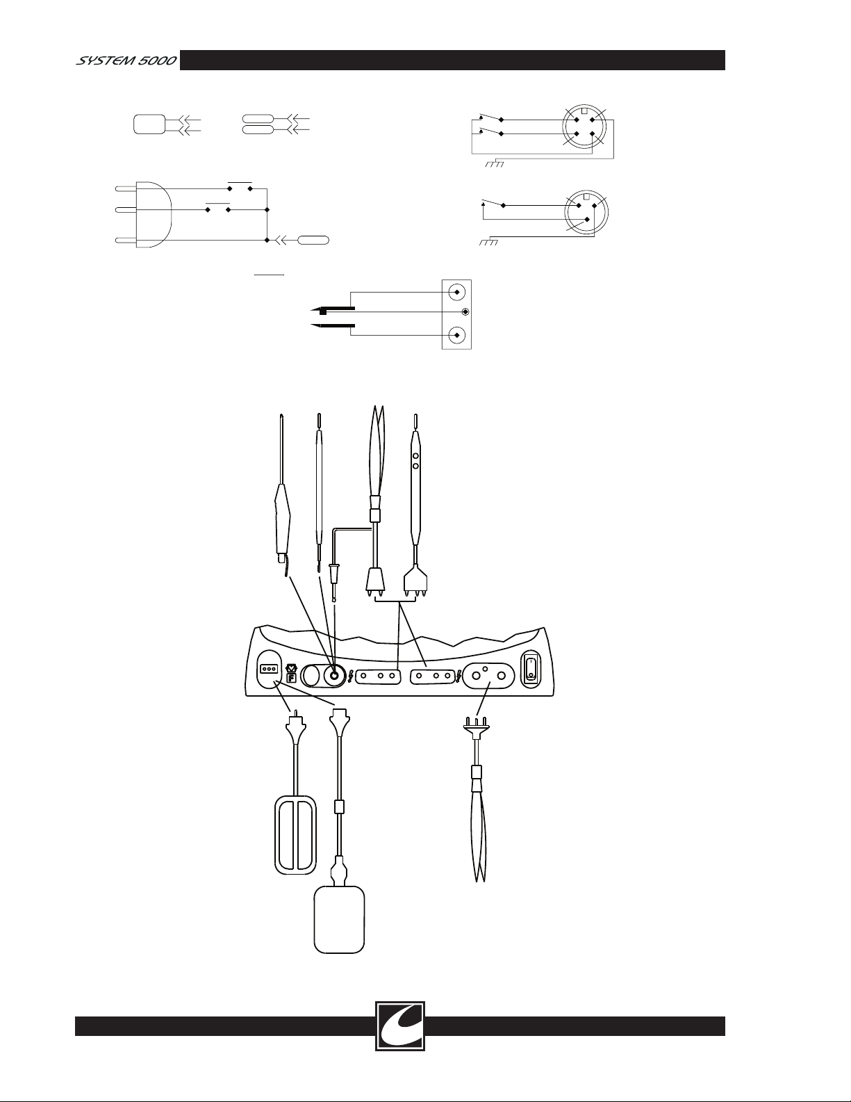
CUT
COAG
RF
MONOPOLAR HANDSWITCHED ACTIVE CONNECTIONS
RF
DUAL FOIL ELECTRODE
RF
SINGLE FOIL ELECTRODE
NEUTRAL ELECTRODE CONNECTIONS
CUT
COAG
RF
RF
HANDSWITCH (OPTIONAL)
RF
A
B
C
D
CUT
COAG
B
A
C
MONOPOLAR HANDSWITCHED ACTIVE CONNECTIONS
BIPOLAR ACTIVE CONNECTIONS
MONOPOLAR FOOTSWITCH CONNECTIONS
BIPOLAR FOOTSWITCH CONNECTIONS
RF
DUAL FOIL ELECTRODE
RF
SINGLE FOIL ELECTRODE
NEUTRAL ELECTRODE CONNECTIONS
CUT
COAG
RF
RF
HANDSWITCH (OPTIONAL)
RF
MONOPOLAR HANDSWITCHED ACTIVE CONNECTIONS
BIPOLAR ACTIVE CONNECTIONS
RF
DUAL FOIL ELECTRODE
RF
SINGLE FOIL ELECTRODE
NEUTRAL ELECTRODE CONNECTIONS
Figure 2.4 Accessory Schematics
2-14
Figure 2.5 Accessory Connections
 Loading...