

Page 1
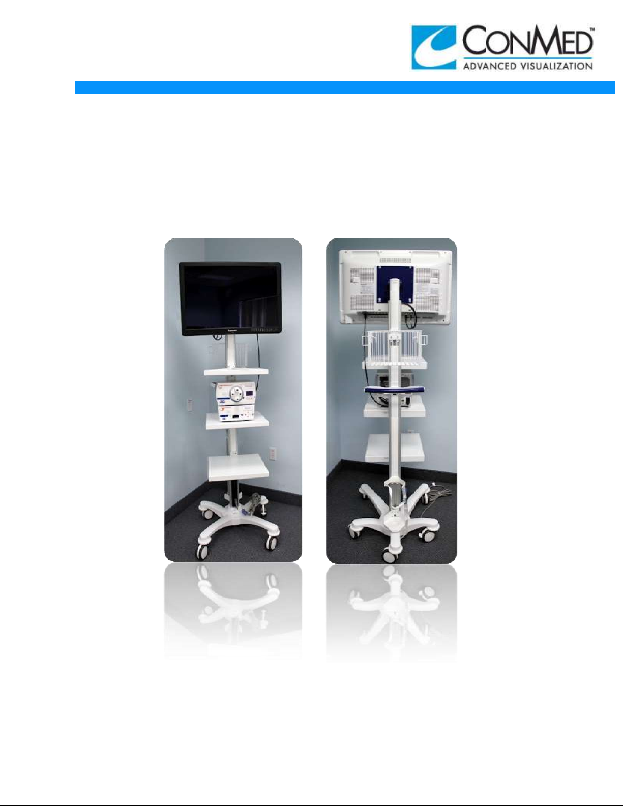
MARKETING COMMUNICATIONS
INSTALLATION GUIDE
11/13/12
3DHD VISION SYSTEM
@2012 by ConMed Corporation- All rights reserved. MCM2012221
This publication is protected by copyright. Copying, disclosure to others, or sue of this publication is prohibited without
express written consent of ConMed Corporation. ConMed Corporation reserves the right to make changes show herein
without notice or obligation. Contact ConMed Corporation or your representative for the latest information.
Page 2
MARKETING COMMUNICATIONS
Note: If any discrepancies cannot be resolved please report immediately to Viking
Systems Technical Support!
[email protected] or call (800) - 200 - 8824
Note: Cart may or may not be shipped on its side, if so, cut strapping to release
cart from pallet and tip cart box to the upright position.
Note: Carts sent outside of the U.S. with the exclusion of Canada, Mexico and
Puerto Rico are shipped without an AC Power Cord. It is the responsibility of the
installer to provide the proper AC Cord.
INSTALLATION GUIDE
11/9/12
3DHD VISION SYSTEM
This installation guide is for use by ConMed Distributors to ensure proper set up of the
ConMed 3DHD Vision System. For more detailed information and for trouble shooting by
product please refer to the product User Manuals which can be found with each of the
individual 3DHD Vision System components.
Tools Required:
Utility Knife
Phillips Screw Driver
Country specific Power Cord for Cart (outside the US, Canada, Mexico, and
Puerto Rico)
6MM Hex Bit Socket Wrench
Alignment Target Part #T05713-001
Tools Supplied:
4MM Allen Wrench
Inspect all shipping packages for any signs of mishandling or damage! In the event of
damage please contact Customer Service:
Email: [email protected] or phone: (800) – 200 – 9824
CART:
To unpack cart cut strapping, remove top cover and slide side packaging up and
over cart.
Lift cart out of packaging base and place on floor.
Inspect for any damages, including cosmetic damages.
Phillips Screw Driver is a registered trademark of Phillips Screw Company
Allen in a registered trademark of Allen Manufacturing Company
2
Page 3
MARKETING COMMUNICATIONS
INSTALLATION GUIDE
3DHD VISION SYSTEM
WARNING: Do not connect AC mains of cart to power.
AC CORD INSTALLATION FOR CART
11/9/12
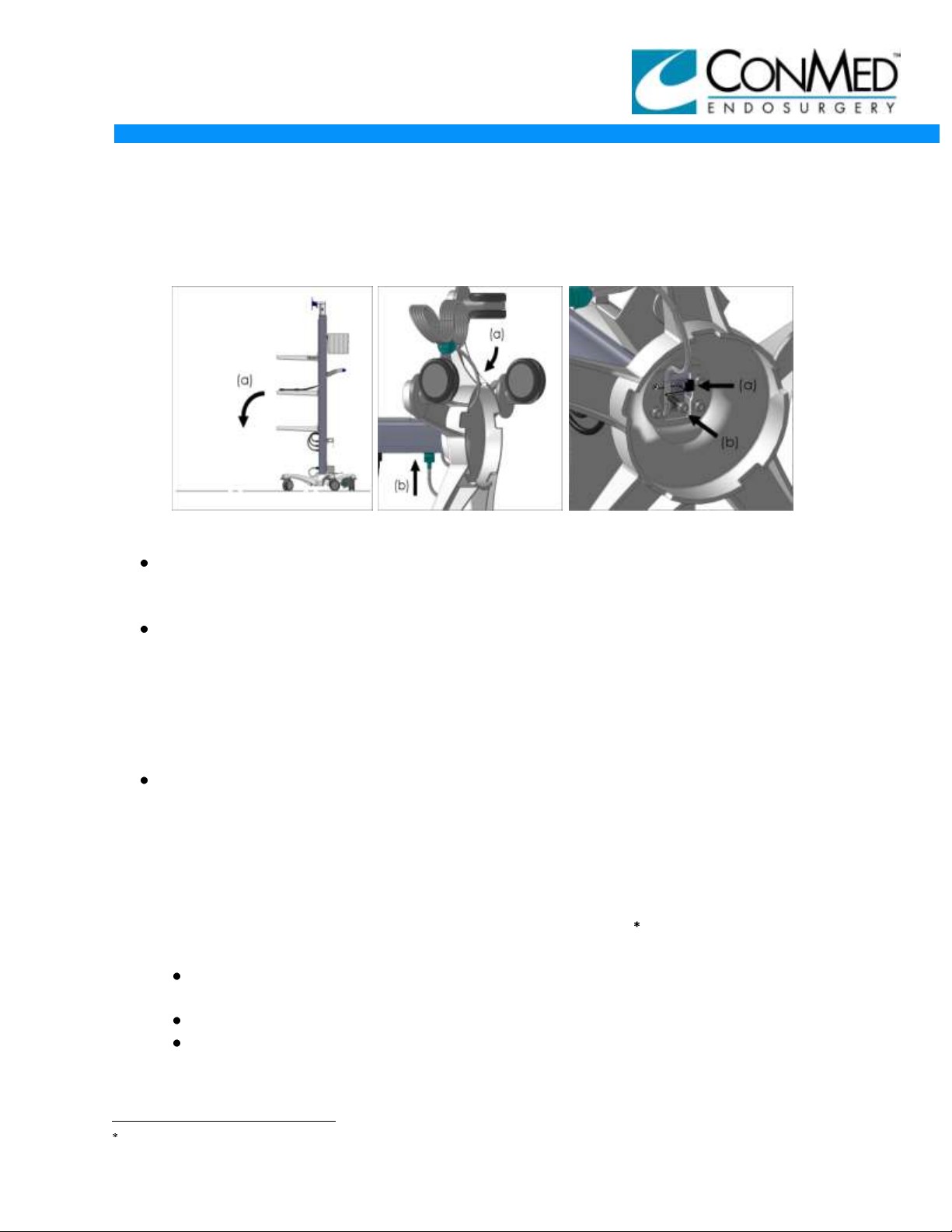
Figure 1 Figure 2 Figure 3
Tip the Video Cart onto its front end, as shown in Figure 1.
a. Un-package the Video Cart and carefully tip the Video Cart onto its front
end.
Insert the Hospital Grade Power Cord into the Base of the Video Cart as shown in
Figure 2.
a. Insert the Hospital Grade power under the Base of the Video Cart and feed
the plug end of the power cord through the space under the Power Strip and
out the front of the Video Cart.
b. Plug the Hospital Grade Power Cord into the outlet under the green pilot
light of Power Strip.
Secure the Hospital Grade Power cord using the clip provided with the Video Cart,
as shown in Figure 3.
a. Remove the Cap Screw and Washer holding the power cord clip using a
6mm hex bit, and place the loose clip onto the Hospital Grade Power Cord.
b. Secure the clip and power cord back onto the Video Cart using the existing
Cap Screw and Washer.
MOUNTING INSTRUCTIONS FOR VIDEO DISPLAY: (SONY)
Open 8272-14 Sony* 3DHD video display monitor box and remove power
supply
Inspect for any damage including cosmetic damages.
Attach monitor Sony* video display AC power supply to mounting bracket
underneath middle shelf of Cart. (Sony* monitor only)
Sony is a registered trademark of Sony Corporation of America.
3
Page 4
MARKETING COMMUNICATIONS
INSTALLATION GUIDE
3DHD VISION SYSTEM
11/9/12
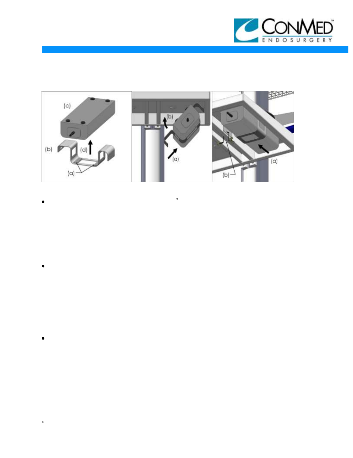
Figure 4 Figure 5 Figure 6
Attach the Mounting Bracket to the Sony Monitor Power Supply as shown in Figure 4.
a. Remove backing from the double sided tape on the Mounting Bracket.
b. Position the Mounting Bracket so the slotted hole is to the left and the double
sided tape is facing up.
c. Position the Power Supply feet facing up with the cord to the Sony* Monitor
facing you.
d. Attach the Mounting Bracket to the Power Supply approximately on center and
press firmly together.
Place the Mounting Bracket & Power Supply under the middle shelf of the Video Cart
as shown in Figure 5.
a. Standing in front of the Video Cart, place the right side of the Mounting Bracket
& Power Supply under the right side of the 2nd shelf with the cord to the Sony*
Monitor facing you.
b. Fold the Mounting Bracket & Power Supply up so it is flat up against the bottom
of the Video Cart shelf. The Mounting Bracket & Power Supply should be
loosely in position, Do no force into place.
Secure the Mounting Bracket & Power Supply to the middle shelf of the Video Cart as
shown in Figure 6.
a. Slide the Mounting Bracket & Power Supply forward until the slotted hole in the
Mounting Bracket is aligned with the mounting hole in the shelf of the Video
Cart.
b. Insert the mounting hardware included with the Mounting Bracket and slide the
Mounting Bracket & Power Supply to the front of the Video Cart until it is snug,
and secure the mounting hardware hand tight.
Sony is a registered trademark of the Sony Corporation of America.
4
Page 5
MARKETING COMMUNICATIONS
INSTALLATION GUIDE
3DHD VISION SYSTEM
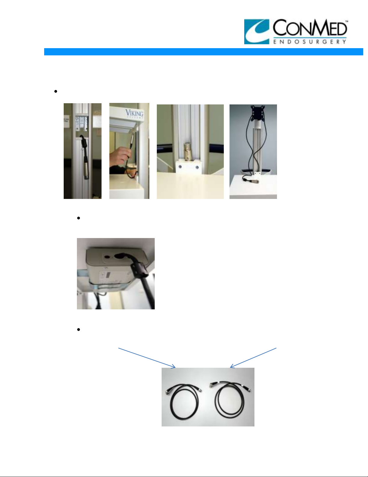
Run 4 prong power cable for monitor video display, through cart channel as shown
in Figures 7-10:
Figure 7 Figure 8 Figure 9 Figure 10
Attach one of the 1 m IEC 320 power cords to power supply as shown in
Figure 11.
11/9/12
Figure 11
Open 3DHD controller packaging and remove HD-SDI cables. Figure 12
indicates Left and Right Cables.
Left = All Black Cable Right = Black cable with white
ring
Figure 12
5
Page 6
MARKETING COMMUNICATIONS
Loosen
Remove
INSTALLATION GUIDE
11/9/12
3DHD VISION SYSTEM
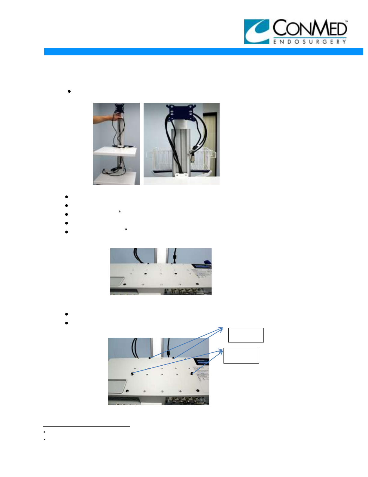
Run the HD-SDI video cables through cart extension channel as shown in
Figures 13 and 14:
Figure 13 Figure 14
Right angle end goes to the CCU (middle shelf).
Reinstall plastic cart column covers.
Unpack Sony 3D monitor.
Inspect for any damages including cosmetic damages.
Vesa Mounting pattern on back of the Sony* monitor, once unpacked should
look like picture shown in Figure 15:
Figure 15
Where Shown:
Loosen the top 2 middle screws
Remove the bottom 2 screws where shown in in Figure 16.
Figure 16
Sony is a registered trademark of Sony Corporation of America.
Vesa Mounting is a trademark of Video Electronic Standards Association.
6
Page 7
MARKETING COMMUNICATIONS
INSTALLATION GUIDE
11/9/12
3DHD VISION SYSTEM
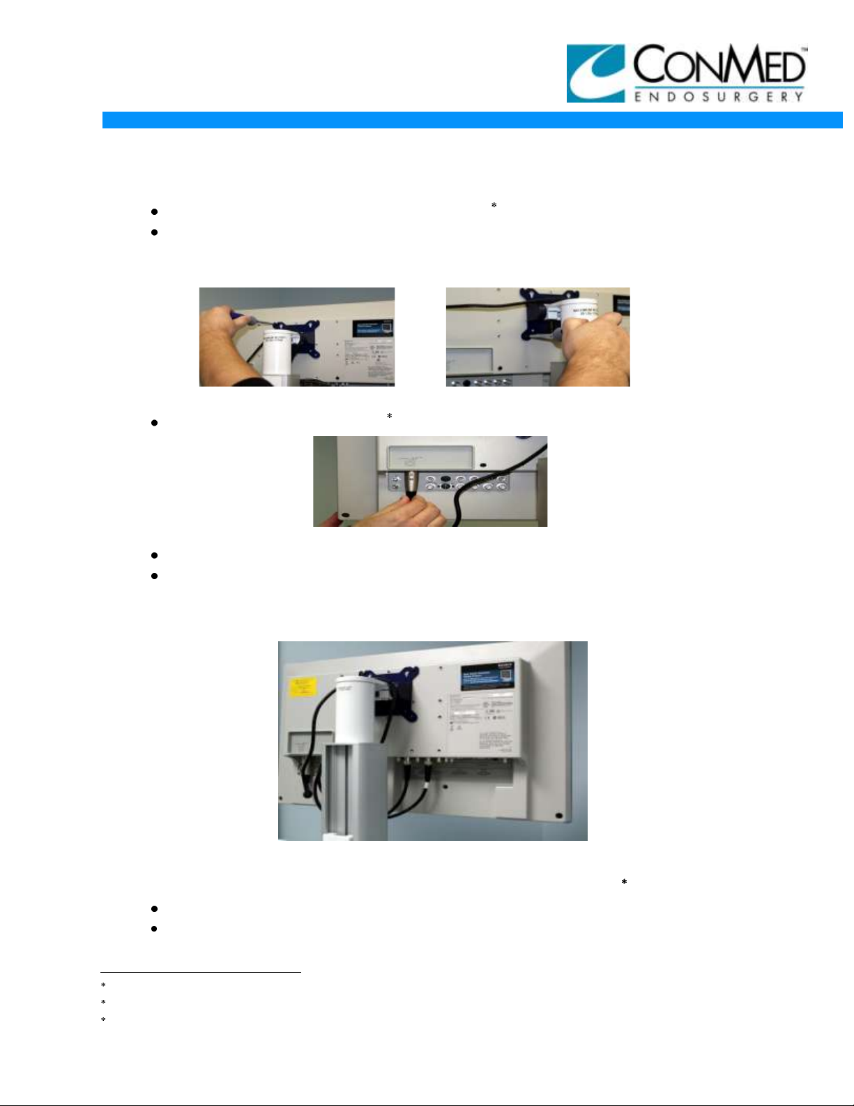
Attach monitor video display to cart’s Vesa mounting bracket.
Attach the remaining two bottom screws to remaining holes in the Vesa*
mounting bracket, tighten all screws, Vesa* bracket should like pictures shown
in Figures 17 and 18:
Figure 17 Figure 18
Connect power cord to Sony monitor video display as shown in Figure 19:
Figure 19
Connect left (black) HD-SDI video cable to Sony* 3G Card input 1
Connect right (white) HD-SDI video cable to Sony* 3G Card input2
MONITOR AT THIS POINT WILL LOOK LIKE FOLLOWING PICTURE IN FIGURE 20
Figure 20
MOUNTING INSTRUCTIONS FOR VIDEO DISPLAY: (PANASONIC)
Unpack 8272-19 Panasonic* 3D monitor video display.
Inspect for any damages including cosmetic damages.
Vesa is a trademark of Video Electronic Standards Association.
Sony is a registered trademark of Sony Corporation of America.
Panasonic is a registered trademark of Panasonic Corporation Japan.
7
Page 8
MARKETING COMMUNICATIONS
INSTALLATION GUIDE
11/9/12
3DHD VISION SYSTEM
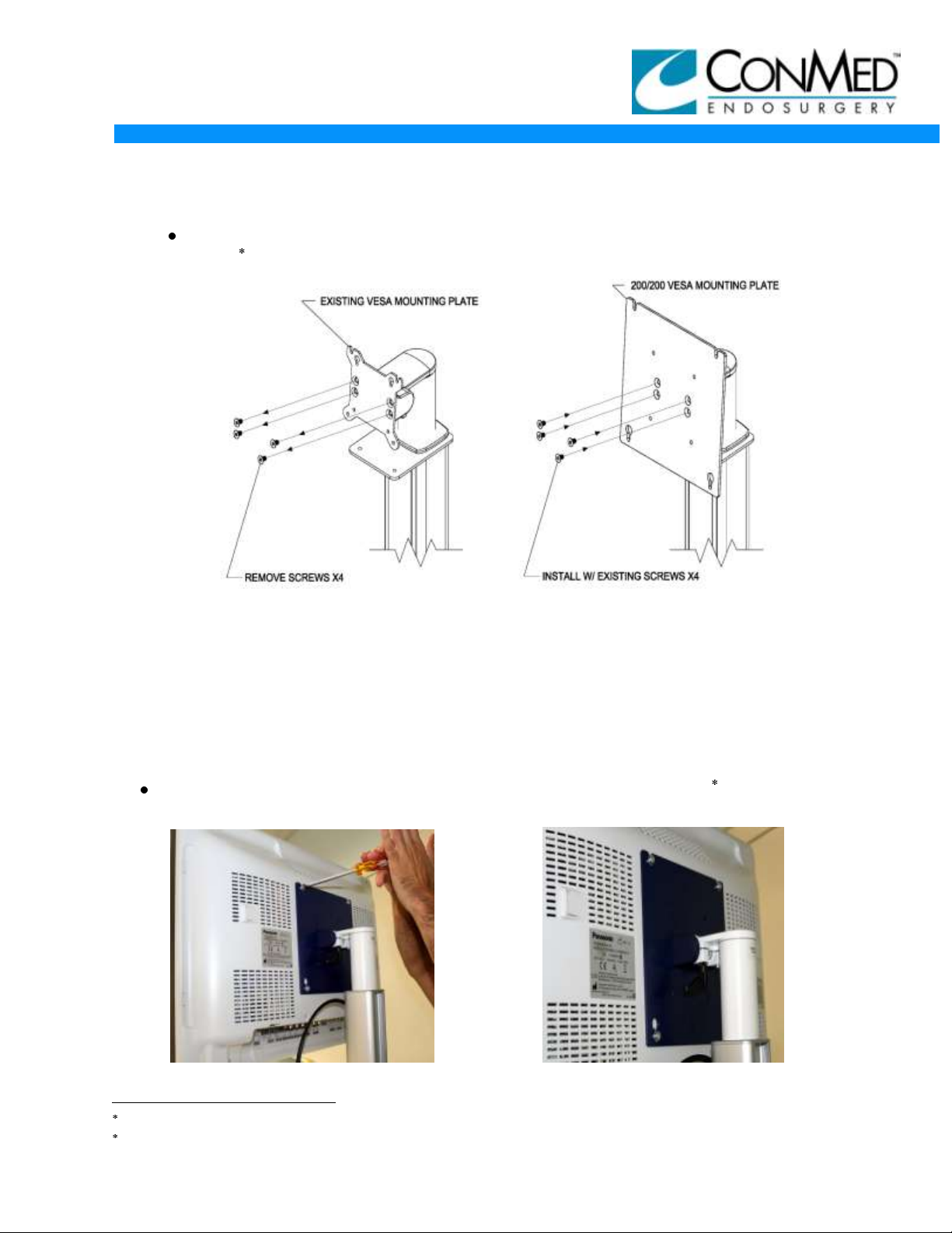
Remove existing vesa mounting plate from the cart and install 200/200 Vesa
Plate as shown below in Figures 21 and 22.
Figure 21 Figure 22
200/200 VESA MOUNTING* PLATE INSTALLATION
1. Remove the four (4) existing screws from the front of the existing tilt / swivel VESA
mount* plate, and remove the existing VESA mounting* plate. See Figure 21.
2. Using the four (4) existing screws, install the 200/200 VESA mounting* plate to the
existing mounting holes provided on the cart. See Figure 22.
Once the 200/200 Vesa Plate* as been installed, place Panasonic monitor video
display on bracket as shown in Figures 23 and 24.
Figure 23 Figure 24
Vesa Mounting is a trademark of Video Electronic Standards Association.
Panasconic is a registered trademark of Panasonic Corporation Japan.
8
Page 9
MARKETING COMMUNICATIONS
Engage Clip
INSTALLATION GUIDE
3DHD VISION SYSTEM
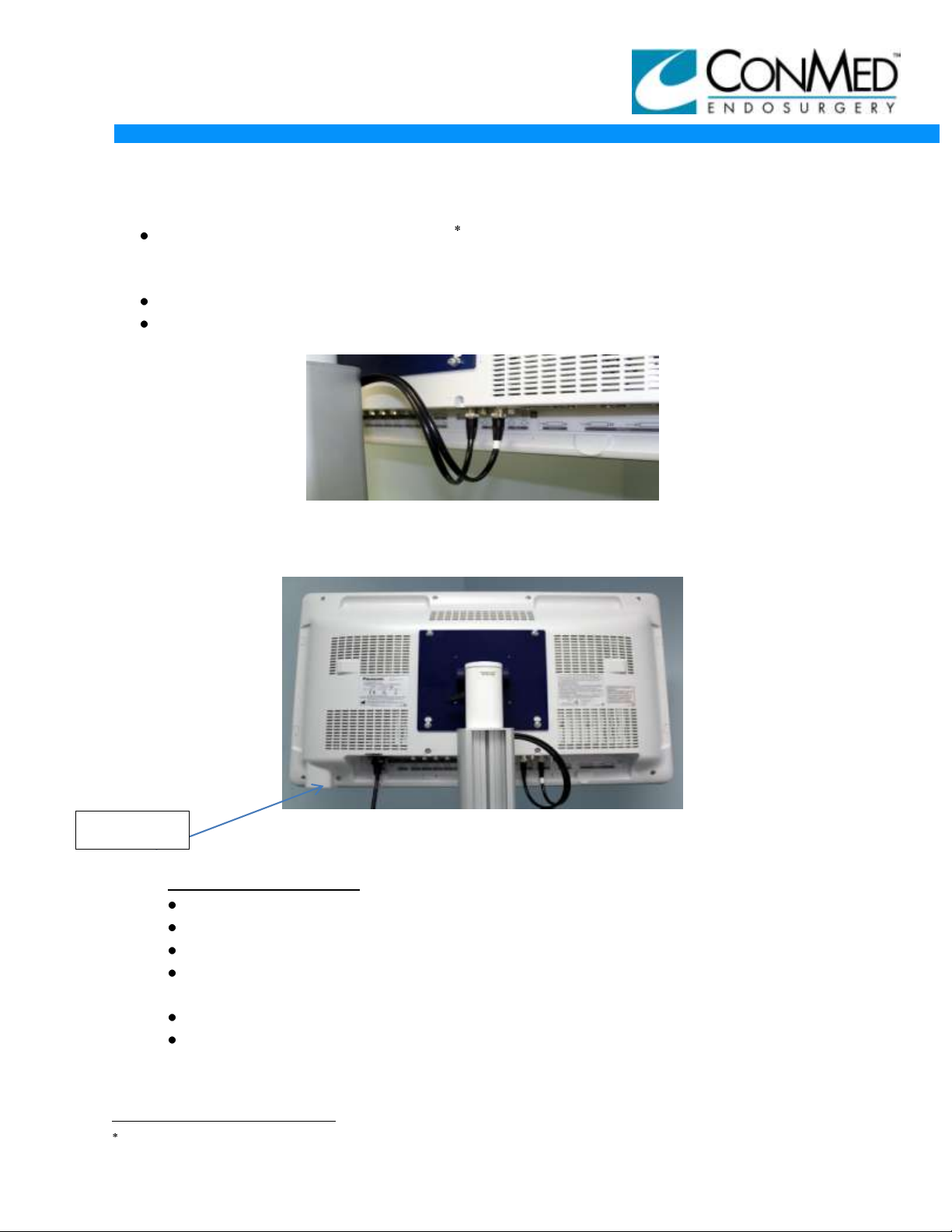
Connect power cord for Panasonic Monitor (There are 3 power cords on the
middle shelf, ensure you use the longest cord (1 1/2MM) ). Ensure the metal clip
on the monitor is engaged to secure the power cord. See Figure 26.
Connect left (black) HD-SDI video cable to the SDI-1 input as shown in Figure 25.
Connect right (white) HD-SDI video cable to the SDI-2 input as shown in Figure 25.
11/9/12
Figure 25
THE MONITOR AT THIS POINT WILL LOOK LIKE THE FOLLOWING PICTURE IN FIGURE 26
Figure 26
3DHD CONTROLLER:
Unpack the 8170-6 3DHD controller.
Inspect for any damages, including cosmetic damages.
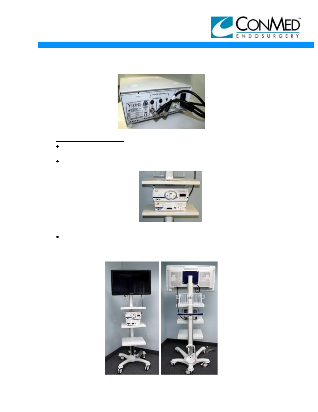
Place the controller on the middle shelf as shown below.
Connect video cables to proper left (black) and right ( white banded) HD-SDI
outputs on controller.
Attach power cord to controller.
Place controller feet in the shelves detents to stabilize unit as shown in
Figure 27.
Panasonic is a registered trademark of Panasonic Corporation Japan.
9
Page 10
MARKETING COMMUNICATIONS
INSTALLATION GUIDE
3DHD VISION SYSTEM
11/9/12
Figure 27
3DHD LIGHT SOURCE:
Unpack the 8050-2 3DHD light source. Inspect for any damage, including
cosmetic damages.
Place the light source on top of the 3DHD controller (position feet in detents on
controller cover). As shown in Figure 28.
Figure 28
Attach power cord to light source.
FINISHED CART ASSEMBLY WILL LOOK LIKE FOLLOWING PICTURES IN
FIGURES 29 and 30
Figures 29 Figure 30
10
Page 11
MARKETING COMMUNICATIONS
NOTE: THESE OPERATIONAL TESTS ARE THE SAME FOR BOTH SINGLE CHANNEL and
INSTALLATION GUIDE
3DHD VISION SYSTEM
OPERATIONAL CHECKS:
Connect cart power cord to power outlet.
Turn on power to monitor video display, camera control unit.
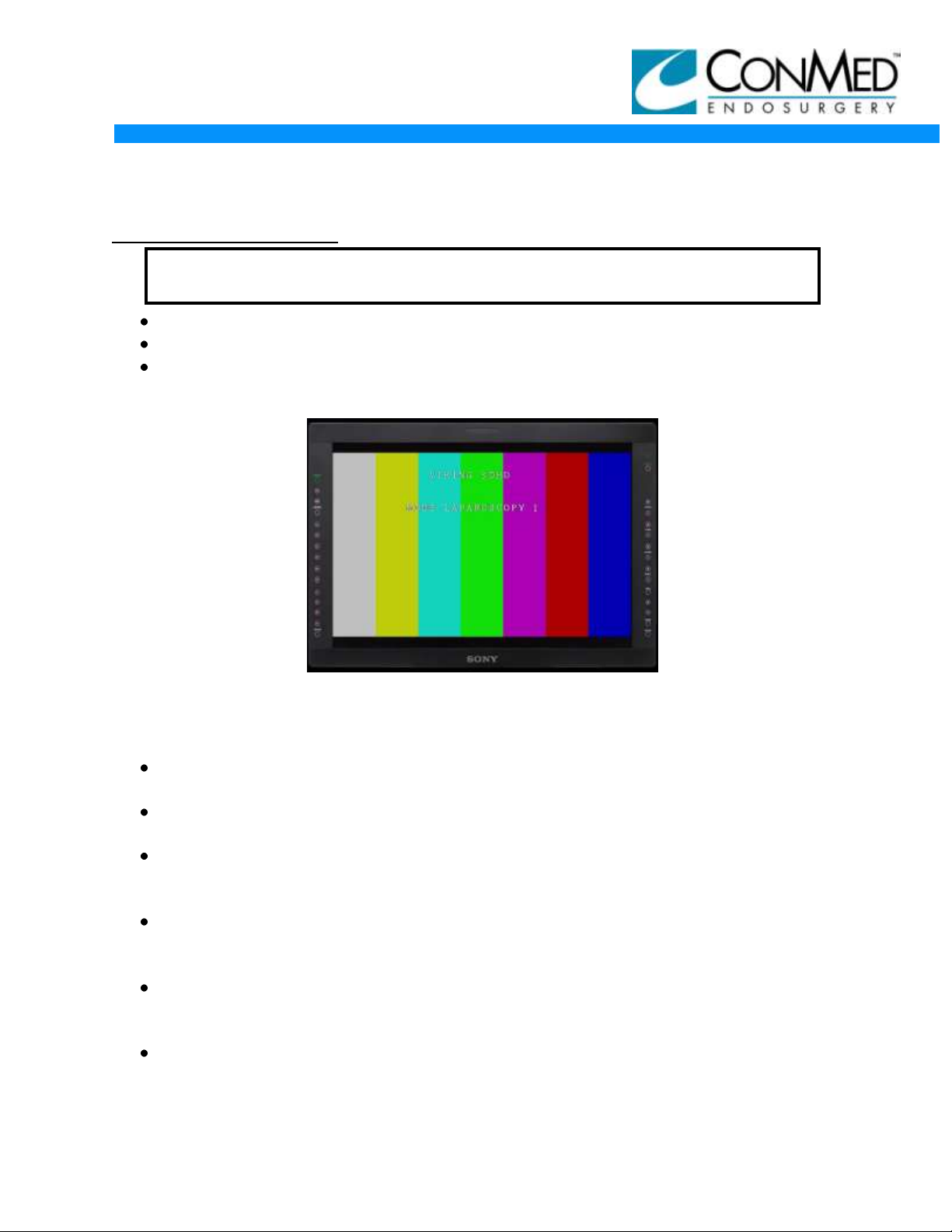
The monitor video display should display color bars with on screen display (OSD)
as shown in Figure 31.
11/9/12
Figure 31
Unpack 3DHD Vision Systems 3DHD glasses, 8272-15 and 8272-16 overwear
glasses.
Put on a pair of 3DHD Vision Systems 3D glasses and view the monitor video
display screen.
Color bars should be present in both right and left eyes. The on screen display
(OSD) should only be present in the left eye. The on screen display (OSD) should
not be visible with right eye only.
Unpack 8170-9 Dual Channel Camera Head or 8170-8 Single Channel Camera
Head and inspect the camera housing and cable for cuts, tears, cracks, or other
defects.
Connect 8170-9 Dual Channel Camera Head or 8170-8 Single Channel Camera
Head to front panel connector on 3DHD controller. NOTE: Ensure that the
camera head connector is facing UP when plugging into the CCU.
Color bars should turn off and video image should now appear on the monitor
video display.
11
Page 12
MARKETING COMMUNICATIONS
OSD Reference
INSTALLATION GUIDE
3DHD VISION SYSTEM
The on screen display (OSD) on the monitor video display screen should display
the following as shown in Figures 32.
Figure 32
Aim and focus Camera Head at an object in the room that has a horizontal edge
(such as a shelf or top of door or doorway).
View monitor video display without Viking 3D Glasses and verify (the double)
image displayed horizontal edges are at the same horizontal plane as shown in
Figure 33.
11/9/12
STEREO ENDOSCOPE:
Figure 33
Unpack the 8191-05/06 Dual Channel Stereo Endoscope or 8191-01/02 Single
Channel Stereo Endoscope.
Inspect the (Dual Channel or Single Channel) Stereo Endoscope for cracks and
other defects.
Look through the scope and check optical system (both Channels for Dual Channel
Scope) for a clear, crisp image. If Image is compromised, clean Endoscope Lens
surface with alcohol, as instructed per Endoscope IFU.
12
Page 13
MARKETING COMMUNICATIONS
INSTALLATION GUIDE
3DHD VISION SYSTEM
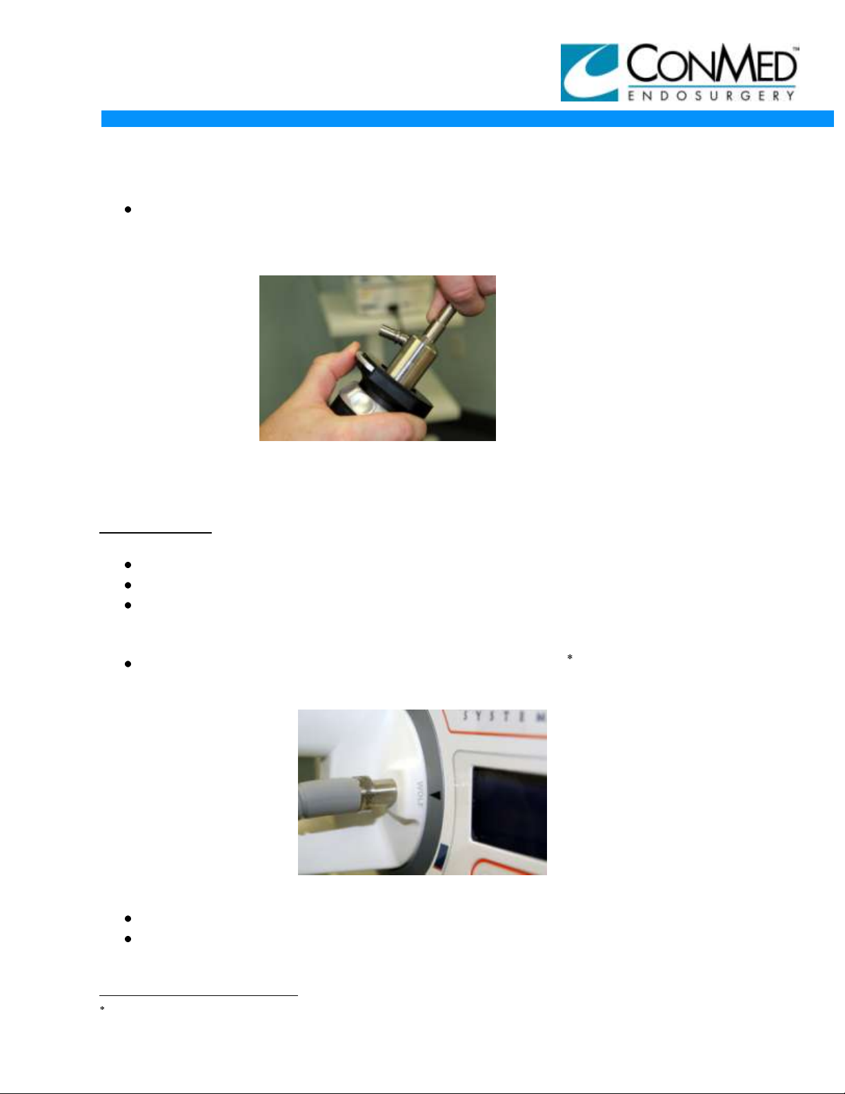
Attach (Dual Channel or Single Channel) Stereo Endoscope to appropriate
Camera Head by pushing down coupler latching feature. Insert Endoscope and
releasing coupler latching feature, as shown in Figure 34.
Figure 34
WARNING: Ensure Endoscope is securely locked to Camera Head.
LIGHT GUIDE:
Unpack the 8054-7 or 8054-8 light guide.
Inspect the outer sheathing for nicks, cuts, or voids.
Aim one end of light guide up at the overhead lighting and view other end to verify
light passing through ( you can cover and uncover end facing toward light with
finger to verify light passing through).
Before attaching light guide to light source verify the Wolf port is at the arrow
position on the front right of light source, as shown in Figure 35.
11/9/12
Figure 35
Connect light guide proximal end to the light source
Connect distal end of light guide to stereo endoscope light post adapter.
Wolf is a tradename of Richard Wolf.
13
Page 14
MARKETING COMMUNICATIONS
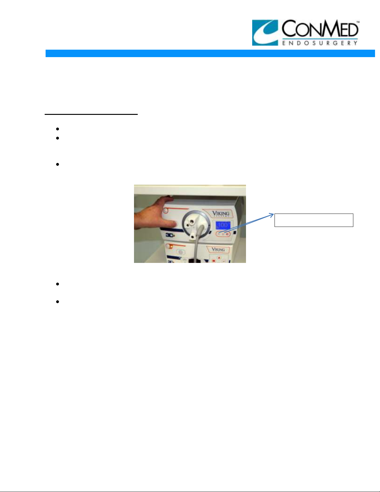
Light Intensity Switch’s
INSTALLATION GUIDE
3DHD VISION SYSTEM
LIGHT SOURCE TESTING:
Turn on 3DHD light source by pressing power button on upper left corner.
When the power switch is pressed the Stand-by Light will blink and there will be a
3 to 4 second delay before Xenon Lamp illuminates, at this time the system is
performing a self-diagnostic check.
Push the Stand By button to allow the light source to emit light to the light guide as
shown as shown in Figure 36:
11/9/12
Figure 36
The tip of the Endoscope should be emitting light. WARNING: Do not aim light
directly into the eyes of another person.
Push the light intensity membrane switches + to increase and – to decrease the
light output or intensity. Range is 0%, 20-100% in 5% increments. Holding the +
or – button will change the intensity more quickly. Verify the light at distal tip of
Endoscope changes levels when light intensity is varied. Set at 100% when done
testing.
14
Page 15
MARKETING COMMUNICATIONS
WHITE BALANCE
IN PROGRESS
MODE LAPAROSCOPY 1
INSTALLATION GUIDE
3DHD VISION SYSTEM
3DHD SYSTEM TESTING:
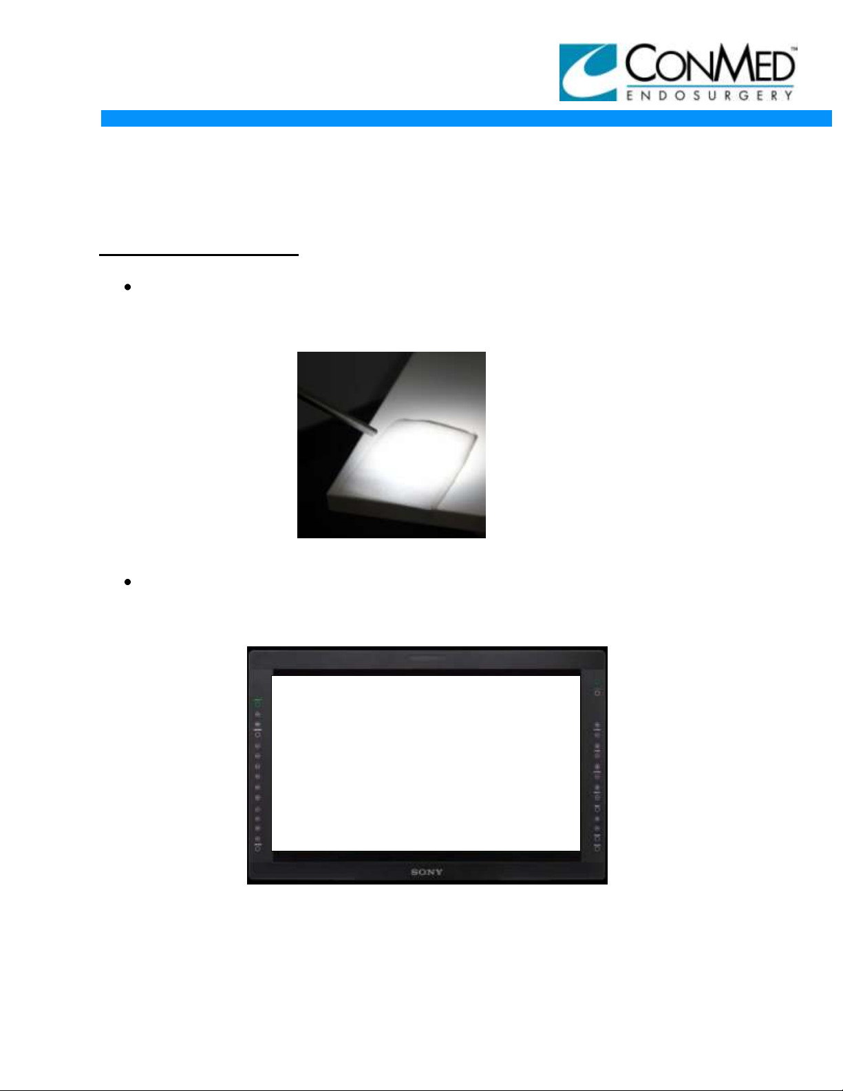
Put on a pair of Viking Systems 3D Glasses and aim 3DHD Camera Head (with
Scope and Light Guide attached) at a non-reflective white object, as shown in
Figure 37.
11/9/12
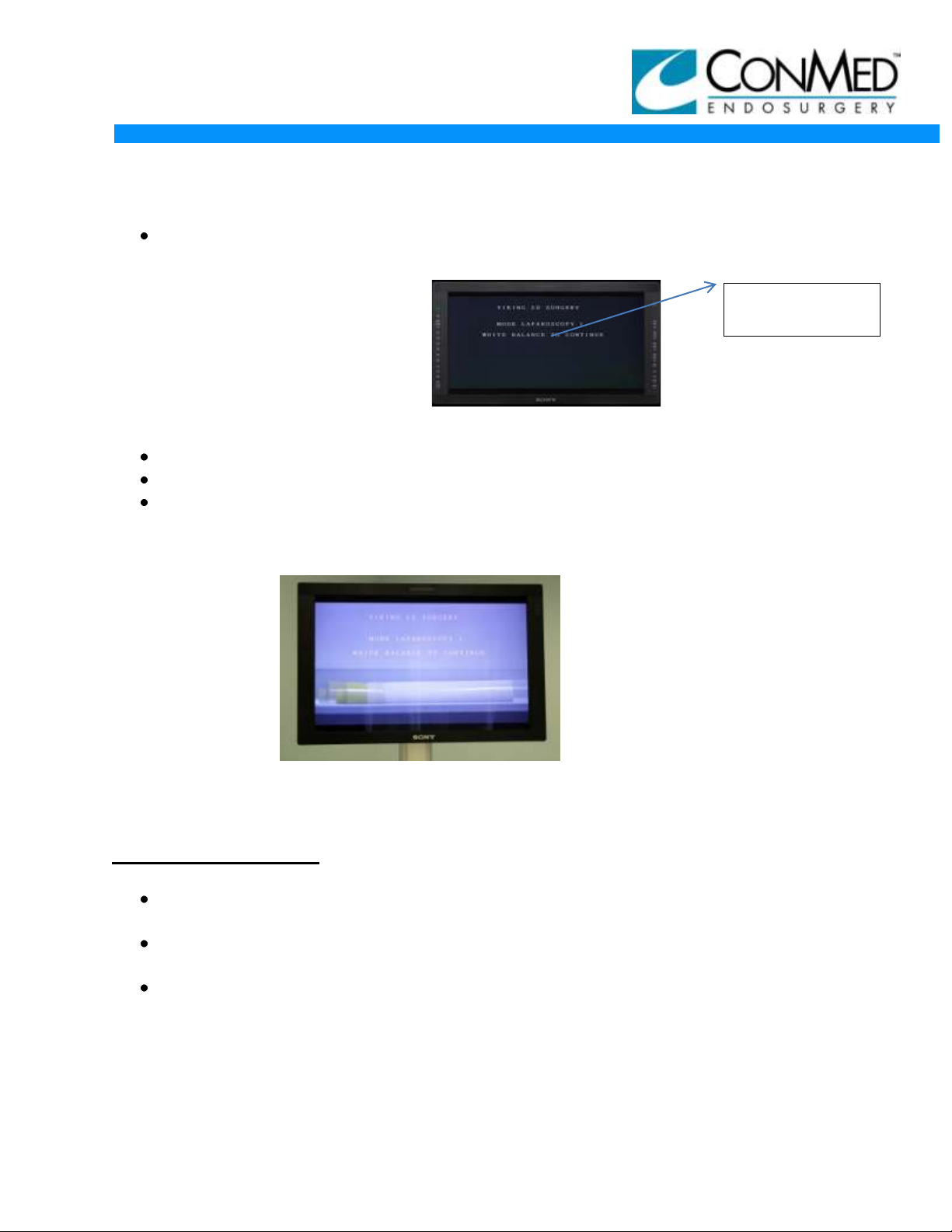
Press White Balance Button on front of camera controller and verify on monitor
screen video display that the on screen display (OSD) looks as shown in
Figure 38:
Figure 37
Figure 38
15
Page 16
MARKETING COMMUNICATIONS
WHITE BALANCE
OK
MODE LAPAROSCOPY 1
INSTALLATION GUIDE
3DHD VISION SYSTEM
Once white balance completes the on screen display (OSD) looks (for a brief
period) as shown is Figure 39.
Figure 39
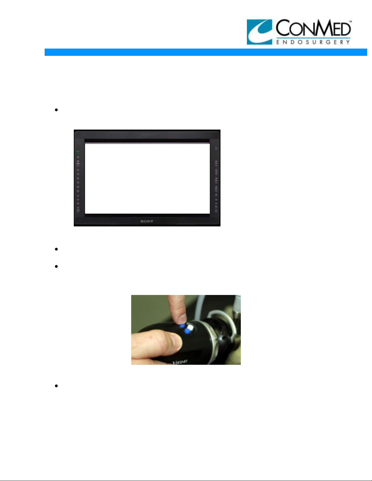
Press and hold the white button on the 3D camera head. The white balance
should initiate and complete as displayed above.
Press and release the left Blue Button on the camera head and the control unit will
beep once. Now press and hold the same left Blue Button and the control unit will
beep twice. The left Blue Button as shown in Figure 40.
11/9/12
Figure 40
Press and release right Blue Button and the brightness on screen display (OSD)
will appear on the monitor. Now when pressing left and right buttons on the
camera head while the brightness is displayed the curser on screen will move left
and right and the video signal brightness on monitor will change.
16
Page 17
MARKETING COMMUNICATIONS
INSTALLATION GUIDE
3DHD VISION SYSTEM
ALIGNMENT OF THE SCOPE/CAMERA:
The alignment should be checked periodically. WARNING: If the system comes
out of alignment it WILL cause eye strain and discomfort. In severe cases 3D
effect will be lost.
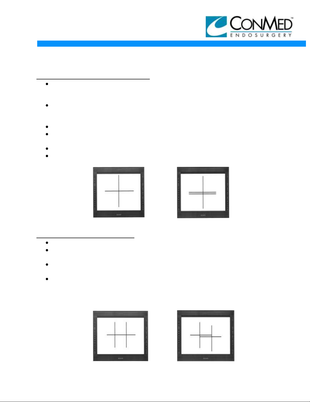
Do not wear Viking System 3D glasses. Hold the tip of the Endoscope
approximately 4 to 5 inches (100 – 130mm) from the alignment target. Targets
Included with Installation Guide.
Rotate the camera so that the long line of the cross is horizontal on the monitor.
Move the Endoscope closer to the target and ensure that the vertical lines of the
two crosses overlap.
Tip of the Endoscope should be approximately 2 inches (50mm) from the target.
The horizontal lines shall also overlap so that there is no visible gap between them,
as shown in Figures 41 and- 42.
Figure 41 - GOOD Figure 42 - BAD
IF MISALIGNMENT IS DETECTED:
Remove the Endoscope from the camera head.
Direct the camera head at the target, keeping its distance from the target
approximately 20 inches (500mm). Observe two images of the target.
Rotate the camera head so that the long line of the cross is made horizontal on the
monitor.
Make sure both lines from the two images are horizontal and overlap. NOTE: The
vertical line will not overlap by design. If the horizontal lines are misaligned as
shown in figure 44 the camera head came out of alignment, most likely having
been dropped. If the camera head is aligned then the scope is the issue, see
figure 43.
Figure 43 - GOOD Figure 44 - BAD
11/9/12
17
Page 18
MARKETING COMMUNICATIONS
OSD Reference for
Test Only
INSTALLATION GUIDE
3DHD VISION SYSTEM
MONITOR PLACEMENT:
It is important to properly position the monitor, if not set up correctly, cross-talk will
be present, causing surgeon’s discomfort, headache, degraded 3D effect or even
complete loss of 3D.
The monitor mount has a swivel joint on the back which allows for tilting. To
correctly set-up monitor it should be tilted in such a way that the imaginary line
perpendicular to the monitor plane coming from the center of the monitor is at the
level of the surgeon’s eyes.
Refer to Monitor User Manual, for illustrations and proper viewing angles.
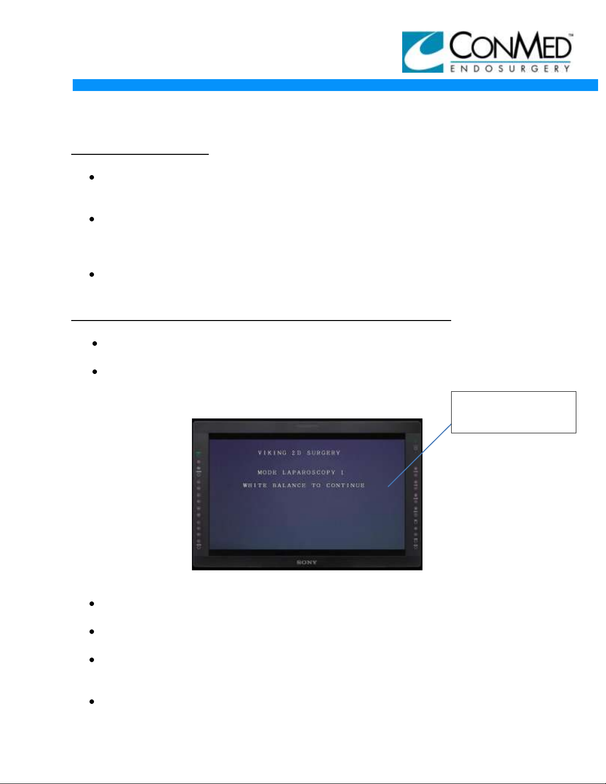
3DHD 2D CAMERA HEAD TESTING IF PURCHASED WITH SYSTEM:
Remove 8170-7 2D camera head from its packaging and inspect the camera
housing and cable for cuts, tears, cracks, or other defects.
Connect camera head to control unit (Attach a C-Mount Coupler if available) and
verify video is present on the monitor video display and on screen display (OSD)
displays as shown in Figures 45.
11/9/12
Figure 45
Aim camera head at white scene and press and hold the right (white) Button on 2D
camera head and the white balance will initiate.
Press and release the right (white) button and the brightness on screen display
(OSD) will appear on monitor.
Now when pressing left and right buttons on the camera head, while the brightness
is displayed, the curser on screen will move left and right. The video signal
brightness on monitor will change.
Allow OSD to clear prior to next step.
18
Page 19

MARKETING COMMUNICATIONS
INSTALLATION GUIDE
3DHD VISION SYSTEM
Press and release the left (blue) button on the camera head and the control unit
will beep once. Now press and hold the same left (blue) Button and the control
unit will beep twice.
To ensure you are achieving full 2D resolution, aim the camera head at an image
and verify wearing the Viking Systems 3D glasses that an image is present in the
left and right eyes (close one eye at a time to verify image presence).
SYSTEM SHUTDOWN:
System can be shut down by unplugging the power cord from the wall, or by
shutting down components individually and then proceeding to unplug from the
wall.
11/9/12
19
 Loading...