

Page 1
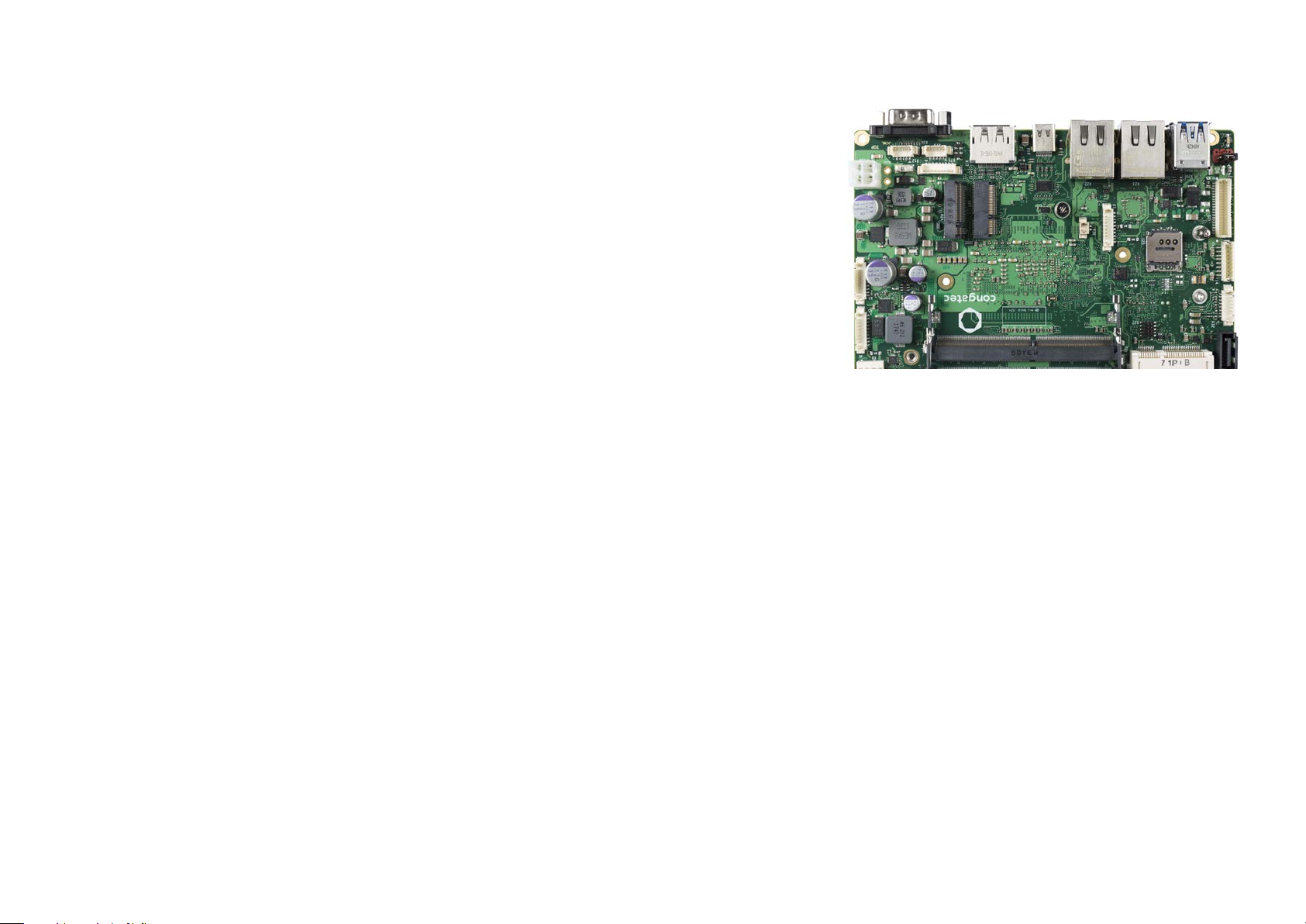
conga-JC370 Juke SBC
8th Generation Intel Core i7, i5, i3 and Celeron Single Chip Ultra Low TDP U-Series SoC
User's Guide
Revision 1.0
Page 2
Revision History
Revision Date (yyyy-mm-dd) Author Changes
0.1 2019-11-19 AEM • Preliminary release
0.2 2020-02-06 AEM
• Updated the ethernet description and Intel AMT version in section 2.1 “Feature List”
• Added note about TSN support to section 5.6 “Ethernet”
• Corrected the signal name of pins 69 and 71 in section 5.2.4 “M.2 Key M Socket”
• Updated table 8 “Power Consumption Values”
• Added BIOS MLF information to 7 “BIOS Setup Description”
• Deleted section 8 “Industry Specifications”
• Official release
Copyright © 2019 congatec AG JCWLm10 2/55
Page 3
Preface
This user's guide provides information about the components, features and connectors available on the conga-JC370 Juke single board
computer.
Disclaimer
The information contained within this user’s guide, including but not limited to any product specification, is subject to change without notice.
congatec AG provides no warranty with regard to this user’s guide or any other information contained herein and hereby expressly disclaims
any implied warranties of merchantability or fitness for any particular purpose with regard to any of the foregoing. congatec AG assumes
no liability for any damages incurred directly or indirectly from any technical or typographical errors or omissions contained herein or for
discrepancies between the product and the user’s guide. In no event shall congatec AG be liable for any incidental, consequential, special, or
exemplary damages, whether based on tort, contract or otherwise, arising out of or in connection with this user’s guide or any other information
contained herein or the use thereof.
Intended Audience
This user's guide is intended for technically qualified personnel. It is not intended for general audiences.
Lead-Free Designs (RoHS)
All congatec AG products are created from lead-free components and are completely RoHS compliant.
Electrostatic Sensitive Device
All congatec AG products are electrostatic sensitive devices. They are enclosed in static shielding bags, and shipped enclosed in secondary
packaging (protective packaging). The secondary packaging does not provide electrostatic protection.
Do not remove the device from the static shielding bag or handle it, except at an electrostatic-free workstation. Also, do not ship or store
electronic devices near strong electrostatic, electromagnetic, magnetic, or radioactive fields unless the device is contained within its original
packaging. Be aware that failure to comply with these guidelines will void the congatec AG Limited Warranty.
Copyright © 2019 congatec AG JCWLm10 3/55
Page 4
Symbols
The following symbols are used in this user's guide:
Warning
Warnings indicate conditions that, if not observed, can cause personal injury.
Caution
Cautions warn the user about how to prevent damage to hardware or loss of data.
Note
Notes call attention to important information that should be observed.
Connector Type
Describes the connector used on the Single Board Computer.
Copyright Notice
Copyright © 2019, congatec AG. All rights reserved. All text, pictures and graphics are protected by copyrights. No copying is permitted
without written permission from congatec AG.
congatec AG has made every attempt to ensure that the information in this document is accurate yet the information contained within is
supplied “as-is”.
Copyright © 2019 congatec AG JCWLm10 4/55
Page 5

Trademarks
Product names, logos, brands, and other trademarks featured or referred to within this user’s guide, or the congatec website, are the property
of their respective trademark holders. These trademark holders are not affiliated with congatec AG, our products, or our website.
Warranty
congatec AG makes no representation, warranty or guaranty, express or implied regarding the products except its standard form of limited
warranty (“Limited Warranty”) per the terms and conditions of the congatec entity, which the product is delivered from. These terms and
conditions can be downloaded from www.congatec.com. congatec AG may in its sole discretion modify its Limited Warranty at any time and
from time to time.
The products may include software. Use of the software is subject to the terms and conditions set out in the respective owner’s license
agreements, which are available at www.congatec.com and/or upon request.
Beginning on the date of shipment to its direct customer and continuing for the published warranty period, congatec AG represents that the
products are new and warrants that each product failing to function properly under normal use, due to a defect in materials or workmanship or
due to non conformance to the agreed upon specifications, will be repaired or exchanged, at congatec’s option and expense.
Customer will obtain a Return Material Authorization (“RMA”) number from congatec AG prior to returning the non conforming product freight
prepaid. congatec AG will pay for transporting the repaired or exchanged product to the customer.
Repaired, replaced or exchanged product will be warranted for the repair warranty period in effect as of the date the repaired, exchanged
or replaced product is shipped by congatec, or the remainder of the original warranty, whichever is longer. This Limited Warranty extends to
congatec’s direct customer only and is not assignable or transferable.
Except as set forth in writing in the Limited Warranty, congatec makes no performance representations, warranties, or guarantees, either
express or implied, oral or written, with respect to the products, including without limitation any implied warranty (a) of merchantability, (b) of
fitness for a particular purpose, or (c) arising from course of performance, course of dealing, or usage of trade.
congatec AG shall in no event be liable to the end user for collateral or consequential damages of any kind. congatec shall not otherwise be
liable for loss, damage or expense directly or indirectly arising from the use of the product or from any other cause. The sole and exclusive
remedy against congatec, whether a claim sound in contract, warranty, tort or any other legal theory, shall be repair or replacement of the
product only.
Certification
congatec AG is certified to DIN EN ISO 9001 standard.
Copyright © 2019 congatec AG JCWLm10 5/55
9
0
0
O
1
S
I
C
N
E
R
O
I
T
T
I
A
F
I
C
TM
Page 6
Technical Support
congatec AG technicians and engineers are committed to providing the best possible technical support for our customers so that our products
can be easily used and implemented. We request that you first visit our website at www.congatec.com for the latest documentation, utilities
and drivers, which have been made available to assist you. If you still require assistance after visiting our website then contact our technical
support department by email at [email protected]
Terminology
Term Description
PCIe Peripheral Component Interface Express
cBC congatec Board Controller
SDIO Secure Digital Input Output
USB Universal Serial Bus
SATA Serial AT Attachment
HDA High Definition Audio
S/PDIF Sony/Philips Digital Interconnect Format
HDMI High Definition Multimedia Interface
DVI Digital Visual Interface
PTT Platform Trust Technology
LPC Low Pin-Count
iDP Internal DisplayPort
I²C Bus Inter-Integrated Circuit Bus
SM Bus System Management Bus
SPI Serial Peripheral Interface
GbE Gigabit Ethernet
LVDS Low-Voltage Differential Signaling
SBC Single Board Computer
PN Part Number
N.C Not connected
N.A Not available
T.B.D To be determined
Copyright © 2019 congatec AG JCWLm10 6/55
Page 7
Contents
1 Introduction .............................................................................10
1.1 The 3.5” SBC Concept ............................................................ 10
1.2 conga-JC370 ............................................................................ 10
1.2.1 Options Information ................................................................. 11
1.2.2 Optional Accessories ............................................................... 11
2 Specification ............................................................................ 13
2.1 Feature List ..............................................................................13
2.2 Supported Operating Systems ................................................ 14
2.3 Mechanical Dimensions ........................................................... 14
2.4 Supply Voltage Power .............................................................. 15
2.5 Power Consumption ................................................................ 15
2.6 Supply Voltage Battery Power .................................................16
2.7 Environmental Specifications ................................................... 17
3 Block Diagram .......................................................................... 18
4 Cooling Solution ...................................................................... 19
4.1 CSA Dimensions ...................................................................... 20
4.2 CSP Dimensions ....................................................................... 21
4.3 HSP Dimensions ....................................................................... 22
5 Connector Description ............................................................. 23
5.1 Power Supply Connectors ........................................................ 23
5.1.1 Mini-Fit 4-Pin Connector .......................................................... 23
5.1.2 USB Type-C Port ...................................................................... 24
5.1.3 Power Status LEDs ................................................................... 24
5.1.4 Power-On Control Jumper ....................................................... 24
5.1.5 CMOS Battery Header ............................................................. 25
5.2 Extension Sockets ................................................................... 26
5.2.1 Mini Card Socket ......................................................................26
5.2.2 M.2 Key B Socket ..................................................................... 27
5.2.3 M.2 Key E Socket ..................................................................... 29
5.2.4 M.2 Key M Socket .................................................................... 30
5.2.5 PCI Express Routing .................................................................32
5.3 Display Interfaces ..................................................................... 33
5.3.1 Display Port .............................................................................. 33
5.3.2 USB Type-C Alternate Mode .................................................... 33
5.3.3 LVDS/eDP Header .................................................................... 34
5.3.3.1 Panel Voltage Selection Jumper .............................................. 35
5.3.3.2 Backlight Control Voltage Selection Jumper ........................... 36
5.3.3.3 Backlight Power Header .......................................................... 36
5.4 USB Connectors ....................................................................... 37
5.4.1 USB 3.1 Gen. 2 Port ................................................................. 37
5.4.2 USB 2.0 Header ....................................................................... 37
5.4.3 USB Type-C Port ...................................................................... 38
5.5 SATA Connectors ..................................................................... 38
5.5.1 Standard SATA Port .................................................................38
5.5.2 mSATA Socket .......................................................................... 39
5.5.3 M.2 Key M Socket .................................................................... 39
5.5.4 SATA Power Header ................................................................. 39
5.6 Ethernet ................................................................................... 40
5.7 HDA Header ............................................................................ 40
5.8 COM Port Headers .................................................................. 42
5.8.1 COM Port 1 and 2 Connectors ................................................ 42
5.8.2 COM Port 3 and 4 Headers ..................................................... 43
5.9 GPIO Header ........................................................................... 44
5.10 System Management Header .................................................. 44
5.11 I²C Bus/SM Bus Header ........................................................... 45
5.12 Front Panel Header .................................................................. 46
5.12.1 CPU Fan Header ...................................................................... 47
6 Additional Features ..................................................................48
6.1 Micro-SIM Card ........................................................................ 48
6.2 Case-open Intrusion Connector ............................................... 49
6.3 External BIOS Flash ................................................................. 49
6.4 congatec Board Controller (cBC) ............................................. 50
6.4.1 Fan Control .............................................................................. 50
6.4.2 Power Loss Control .................................................................. 50
6.4.3 Board Information .................................................................... 50
Copyright © 2019 congatec AG JCWLm10 7/55
Page 8

6.5 OEM BIOS Customization ........................................................ 50
6.5.1 OEM Default Settings .............................................................. 50
6.5.2 OEM Boot Logo ....................................................................... 51
6.5.3 OEM POST Logo ..................................................................... 51
6.5.4 OEM BIOS Code/Data ............................................................. 51
6.5.5 OEM DXE Driver ...................................................................... 51
6.6 congatec Battery Management Interface ................................ 52
6.7 API Support (CGOS) ................................................................ 52
6.8 Thermal and Voltage Monitoring ............................................. 52
6.9 Security Features ......................................................................53
6.10 External System Wake Event ...................................................53
7 BIOS Setup Description ........................................................... 54
7.1 Navigating the BIOS Setup Menu ........................................... 54
7.2 BIOS Versions...........................................................................54
7.3 Updating the BIOS ................................................................... 55
7.4 Supported Flash Devices ......................................................... 55
Copyright © 2019 congatec AG JCWLm10 8/55
Page 9
List of Tables
Table 1 conga-JC370 Variants ..............................................................11
Table 2 Cooling .................................................................................... 11
Table 3 Cables ...................................................................................... 12
Table 4 Adapters .................................................................................. 12
Table 5 Power Supply ........................................................................... 12
Table 6 Feature Summary ..................................................................... 13
Table 7 Measurement Description ........................................................15
Table 8 Power Consumption Values .....................................................16
Table 9 CMOS Battery Power Consumption ........................................ 16
Table 10 Cooling Solution Variants ......................................................... 19
Table 11 Connector X34 Pinout Description .......................................... 23
Table 12 D57 LED States ........................................................................ 24
Table 13 Auto Power-On Control ........................................................... 24
Table 14 X36 Pin Header ........................................................................ 25
Table 15 X26 Pinout Description ............................................................ 26
Table 16 X24 Pinout Description ............................................................ 27
Table 17 X27 Pinout Description ............................................................ 29
Table 18 X28 Pinout Description ............................................................ 30
Table 19 Connector X15 Pinout Description ......................................... 34
Table 20 JP1 Pinout Description .............................................................35
Table 21 JP3 Pinout Description .............................................................36
Table 22 Connector X14 Pinout Description .......................................... 36
Table 23 Connector X21 Pinout Description .......................................... 37
Table 24 X30 Pinout Description. ........................................................... 39
Table 25 GbE LED Description ............................................................... 40
Table 26 X31 Pinout Description ............................................................ 40
Table 27 X32 Pinout Description ............................................................ 41
Table 28 X11 Pinout Description ............................................................ 42
Table 29 X10 Pinout Description ............................................................ 42
Table 30 X12/X13 Pinout Description ....................................................43
Table 31 X5 Pinout Description .............................................................. 44
Table 32 X6 Pinout Description .............................................................. 44
Table 33 X7 Pinout Description .............................................................. 45
Table 34 X4 Pinout Description .............................................................. 46
Table 35 X9 Pinout Description .............................................................. 47
Table 36 X25 Pinout Description ............................................................ 48
Table 37 X3 Pinout Description .............................................................. 49
Table 38 X37 Pinout Description ............................................................ 49
Copyright © 2019 congatec AG JCWLm10 9/55
Page 10
1 Introduction
1.1 The 3.5” SBC Concept
The 3.5” SBC provides enthusiasts and manufacturers with a standardized ultra compact platform for development. With a footprint of
146 mm x 102 mm, this scalable platform promotes the design of highly integrated, energy efficient systems. Due to its small size, the 3.5” SBC
form factor enables PC appliance designers not only to design attractive low cost devices but also allows them to explore a huge variety of
product development options—from compact space-saving designs to fully functional Information Station and Value PC systems. This helps to
reduce product design cycle and encourages rapid innovation in system design, to meet the ever-changing needs of the market.
Additionally, the boards can also be passively cooled, presenting opportunities for fanless designs. The 3.5” SBC boards are equipped with
various interfaces such as PCI Express, SATA, USB 2.0/3.0, Ethernet, Displays and Audio.
1.2 conga-JC370
The conga-JC370 is a Single Board Computer with 3.5” form factor. The conga-JC370 features the 8th Generation Intel Core UE-Series
processors. With 15 W base TDP, the SBC offers Ultra Low Power boards with high computing performance and outstanding graphics.
Additionally, the SBC supports dual channel DDR4 up to 2400 MT/s for a maximum system memory capacity of 64 GB, multiple I/O interfaces,
up to three independent displays and various congatec embedded features.
With smaller board size and lower height keep-out zones, the conga-JC370 SBC provides manufacturers and system designers with the
opportunity to design compact systems for space restricted areas.
The various features and capabilities offered by the conga-JC370 makes it ideal for the design of compact, energy efficient, performanceoriented embedded systems.
Copyright © 2019 congatec AG JCWLm10 10/55
Page 11
1.2.1 Options Information
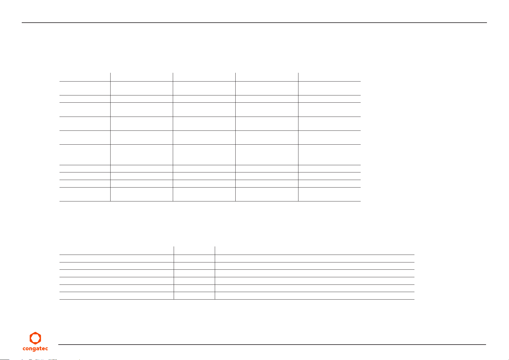
The conga-JC370 is currently available in four variants. The table below show the different configurations available.
Table 1 conga-JC370 Variants
Part-No. 054001 054002 054003 054005
Processor Intel® Core™ i7-8665UE
®
Intel
Smart Cache 8 MB 6 MB 4 MB 2 MB
Max. Turbo
Frequency
Processor Graphics Intel
GFX Base/Max.
Dynamic Freq.
DDR4 Memory 2400 MT/s dual channel
USB Type-C USB/DP USB/DP USB/DP USB/DP
LVDS Ye s Yes Yes Ye s
DisplayPort DP++ DP++ DP++ DP++
Processor TDP
(cTDP )
1.7 GHz Quad Core™
4.4 GHz 4.1 GHz 3.9 GHz N.A
®
UHD Graphics 620
(GT2)
0.3 / 1.15 GHz 0.3 / 1.05 GHz 0.3 / 1.0 GHz 0.3 / 1.0 GHz
Non-ECC
(up to 64 GB)
15 W
(12.5/25 W)
Intel® Core™ i5-8365UE
1.6 GHz Quad Core™
Intel® UHD Graphics 620
(GT2)
2400 MT/s dual channel
Non-ECC
(up to 64 GB)
15 W
(12.5/25 W)
Intel® Core™ i3-8145UE
2.2 GHz Dual Core™
Intel® UHD Graphics 620
(GT2)
2400 MT/s dual channel
Non-ECC
(up to 64 GB)
15 W
(12.5/25 W)
Intel® Celeron® 4305UE
2.0 GHz Dual Core
Intel® UHD Graphics 610
(GT1)
2133 MT/s dual channel
Non-ECC
(up to 64 GB)
15 W
(12.5 W)
1.2.2 Optional Accessories
Table 2 Cooling
Accessories Part No. Description
conga-JC370/CSA-B 054050 12 V active cooling solution with bore-hole standoffs
conga-JC370/CSA-T 054051 12 V active cooling solution with threaded standoffs
conga-JC370/CSP-B 054052 Passive cooling solution with bore-hole standoffs
conga-JC370/CSP-T 054053 Passive cooling solution with threaded standoffs
conga-JC370/HSP-B 054054 Heatspreader with bore-hole standoffs
conga-JC370/HSP-T 054055 Heatspreader with threaded standoffs
Copyright © 2019 congatec AG JCWLm10 11/55
Page 12
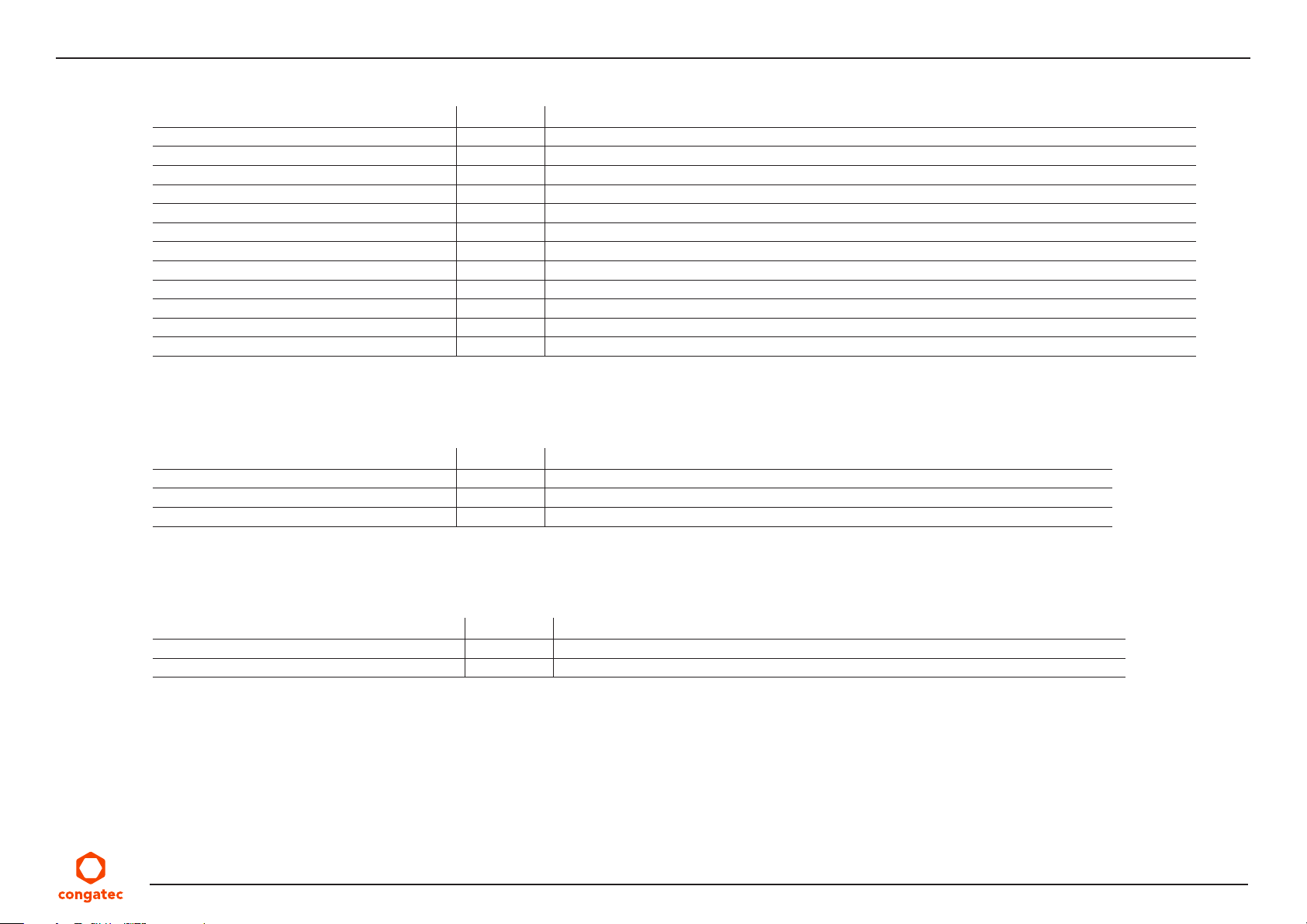
Table 3 Cables
Cables Part No. Description
cab-MITX-eDP 1-1 14000129 40-pin ACES eDP cable (to be combined with PNs: 052231, 052232 and 052234)
cab-Pico-ITX-Buttons-LED 14000147 15 cm internal buttons and LEDs cable
cab-Pico-ITX-GPIO 14000151 15 cm GPIO cable with open end
cab-Pico-ITX-RS232 14000152 15 cm 5-wire RS232 cable adapter (DSUB9 male)
cab-Pico-ITX-SATA-Power 14000205 15 cm SATA power cable for 2.5” HDD only (+5V only)
cab-Pico-ITX-USB20-Twin 14000210 20 cm USB cable adapter with 2x5 pin, 2 mm pitch female header and two USB Type-A receptacle
cab-DSUB9M-PB9 14000252 15 cm male DSUB9 to 9-pin picoblade cable adapter
cab-Backlight ZHR-8 14000253 50 cm backlight cable with ZHR-8 connector and open end
cab-LVDS SHDR-40V 14000254 50 cm, 40-pin LVDS cable with JST SHDR-40 connector and open end
cab-Backlight ZHR-8 14000255 50 cm backlight cable with ZHR-8 connector and open end
cab-LVDS SHDR-40V FI-X30HL 14000256 50 cm, 40-pin LVDS cable with JST SHDR-40 and JAE FI-X30HL connectors
SATA III cable 48000029 30 cm SATA III cable with straight-straight connectors
Table 4 Adapters
Adapters Part No. Description
conga-Thin MITX/eDP to DP adapter 052231 eDP to standard DP adapter for variants with iDP
conga-Thin MITX/eDP to HDMI adapter 052232 eDP to standard HDMI adapter for variants with iDP
conga-eDP to LVDS Adapter 052234 eDP to LVDS adapter for variants with iDP
Table 5 Power Supply
PSU Part No. Description
Power supply (90 W, 19 V @ 4.74 A) 10000146 FSP090-DIEBN2, Plug 7.4 x 5.1 x 12.5 mm
Power cable adapter 14000266 7.4 x 5 mm female connector to MiniFIT 2 x 2 connector
Copyright © 2019 congatec AG JCWLm10 12/55
Page 13
2 Specification
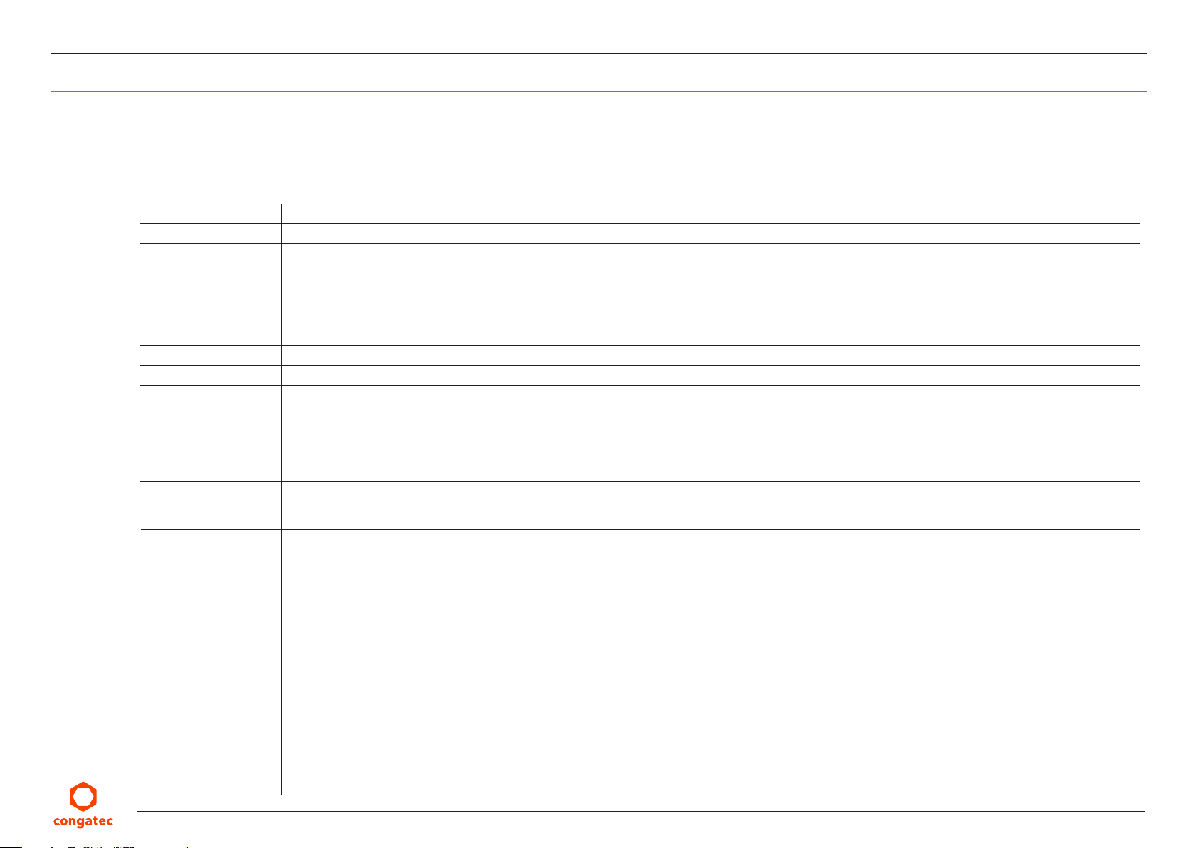
2.1 Feature List
Table 6 Feature Summary
Form Factor
Processor
Memory
congatec Board
Controller
Chipset
Audio
Ethernet
Graphic Interfaces
Back Panel I/O
Connectors
Onboard I/O
Connectors
Optional Onboard
Interfaces
Based on 3.5” form factor (146 x 102 mm)
8th Generation Intel® Core™ i7,i5, i3 and Celeron Single Chip Ultra Low TDP Processors
Two memory sockets (located on the top side of the conga-JC370). Supports
- SO-DIMM non-ECC DDR4 modules
- Data rates up to 2400 MT/s
- Maximum 64 GB capacity (32 GB each)
Multi-stage watchdog, non-volatile user data storage, manufacturing and board information, board statistics, hardware monitoring, fan control, I2C
bus, Power loss control
Intel® 300 Series PCH-LP integrated in the Multi-Chip Package
Realtek ALC888S-VD High Definition Audio
2x Gigabit Ethernet via:
1x DP++
1x LVDS/eDP
1x USB Type-C (DP)
1x DisplayPort++
1x USB Type C (alternate mode)
Extension Sockets:
SATA Connectors:
Audio
1x CAN header
1x HDMI (DP is not supported with this option)
1x GPIO header (GPIO 8-15 with System Management overlay)
1x iDP header (this option does not support DP on USB Type-C)
1x eDP (with LVDS overlay)
®
- Intel
- Intel
- 1x M.2 key B, type 3042/2242 (PCIe x2/USB/SIM)
- 1x M.2 key E, type 2230 (PCIe x1/USB/CNVi)
- 1x M.2 key M, type 2280 (PCIe x4/SATA/Intel
- 1x Mini Card full-size or half-size (PCIe x1/SATA/USB)
- 1x Standard SATA 3.0/eSATA/SATADOM
- 1x SATA power header (5 V)
- 1x Front panel header (HP-Out, MIC)
- 1x Internal audio header (Line-Out, DMIC)
l219-LM for i7 and i5 variants (supports vPro/AMT) or l219-V for i3 and Celeron variants
®
I225-LM (with support for TSN) or Intel I255-V (without TSN)
®
Optane™)
2x USB 3.1 Gen 2
2x Gigabit Ethernet
1x COM port (COM1)
1x LVDS connector (top-side)
1x Backlight power connector
1x Micro-SIM card slot
1x COM port (COM2)
1x Mini-FIT power connector
1x Dual USB 2.0 header
1x Intrusion detection header (case open)
2x COM ports (COM3 and COM4)
1x CPU fan header (12 V only)
1x Front panel header (power button, reset,sleep, LEDs)
1x GPIO header (GPIO 0–7)
1x SMB/I2C connector
Copyright © 2019 congatec AG JCWLm10 13/55
Page 14
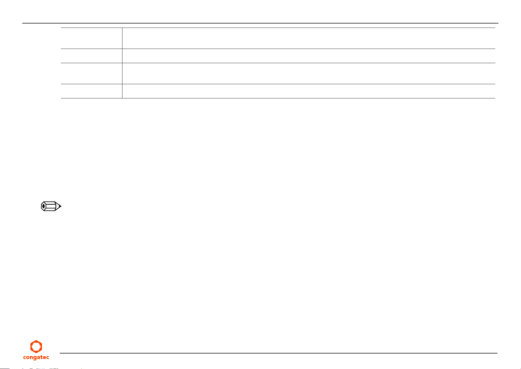
Other Features
BIOS
Power
Management
Security
Thermal and voltage monitoring
CMOS Battery
congatec standard BIOS (also possible to boot from an external BIOS flash)
AMI Aptio® V UEFI 2.6 firmware
32 MB serial SPI flash with congatec Embedded BIOS features
ACPI 4.0 compliant with battery support. Also supports Suspend to RAM (S3) and Intel AMT 11.
Configurable TDP
Ultra low standby power consumption, deep sleep.
Firmware TPM 2.0 (Intel PTT)
Discrete TPM 2.0 (Infineon SLB9670)
2.2 Supported Operating Systems
The conga-JC370 supports the following operating systems.
• Microsoft® Windows
• Microsoft® Windows
®
10
®
10 IoT Enterprise
• Linux 3.x/4.x
• Yocto
• Real Time Systems Hypervisior
Note
The Intel® Whisky Lake SoC supports only 64-bit operating systems.
2.3 Mechanical Dimensions
• 146 mm x 102 mm
• 20 mm height (15 mm top-side, 5 mm bottom-side)
Copyright © 2019 congatec AG JCWLm10 14/55
Page 15
2.4 Supply Voltage Power
• 12–24 V DC ± 5 %
2.5 Power Consumption
The power consumption values were measured using the following test setup:
• Input voltage +12 V
• conga-JC370 SBC
• conga-JC370 CSA
• Microsoft Windows 10 (64 bit)
Note
The CPU was stressed to its maximum workload with the Intel® Thermal Analysis Tool.
Table 7 Measurement Description
The power consumption values were recorded during the following system states:
System State Description Comment
S0: Minimum value Lowest frequency mode (LFM) with minimum core voltage during
desktop idle
S0: Maximum value Highest frequency mode (HFM/Turbo Boost). The CPU was stressed to its maximum frequency
S0: Peak current Highest current spike during the measurement of “S0: Maximum
value”. This state shows the peak value during runtime
S3 SBC is powered by 12 V
S5 SBC is powered by 12 V
Consider this value when designing the system’s power supply, to ensure
sufficient power is supplied during worst case scenarios
Note
1. The fan and SATA drives were powered externally.
2. All other peripherals except the LCD monitor were disconnected before measurement.
Copyright © 2019 congatec AG JCWLm10 15/55
Page 16
Table 8 Power Consumption Values
The table below provides additional information about the conga-JC370 power consumption. The values are recorded at various operating
mode.
Part
No.
054001 2 x 4 GB A.2 R124 Windows 10 Intel® Core™ i7-8665UE 4 1.7 / 4.4 GHz 0.33 1.62 2.03 0.07 0.05
054002 2 x 4 GB A.2 R124 Windows 10 Intel
054003 2 x 4 GB A.2 R124 Windows 10 Intel
054005 2 x 4 GB A.2 R124 Windows 10 Intel
Memory
Size
H.W
Rev.
BIOS
Rev.
OS (64 bit) CPU Current (Amp.)
Variant Cores Freq. /Max. Turbo S0: Min S0: Max S0: Peak S3 S5
Note
With a fast input voltage rise time, the inrush current may exceed the measured peak current.
2.6 Supply Voltage Battery Power
Table 9 CMOS Battery Power Consumption
RTC @ Voltage Current
-10oC 3 V DC 6.22 µA
o
C 3 V DC 2.77 µA
20
o
C 3 V DC 2.04 µA
70
Note
®
Core™ i5-8365UE 4 1.6 / 4.1 GHz 0.45 1.63 1.97 0.11 0.09
®
Core™ i3-8145UE 2 2.2 / 3.9 Ghz 0.34 3.15 3.98 0.07 0.05
®
Celeron® 4305UE 2 2.0 / N.A GHz 0.32 0.92 1.08 0.07 0.05
1. Do not use the CMOS battery power consumption values listed above to calculate CMOS battery lifetime.
2. Measure the CMOS battery power consumption in your customer specific application in worst case conditions (for example, during high
temperature and high battery voltage).
3. Consider also the self-discharge of the battery when calculating the lifetime of the CMOS battery. For more information, refer to application
note AN9_RTC_Battery_Lifetime.pdf on congatec AG website at www.congatec.com/support/application-notes.
4. We recommend to always have a CMOS battery present when operating the conga-JC370
Copyright © 2019 congatec AG JCWLm10 16/55
Page 17
2.7 Environmental Specifications
Temperature Operation: 0° to 60°C Storage: -20° to +70°C
Humidity Operation: 10% to 90% Storage: 5% to 95%
Note
The above operating temperatures must be strictly adhered to at all times. Humidity specifications are for non-condensing conditions.
Copyright © 2019 congatec AG JCWLm10 17/55
Page 18
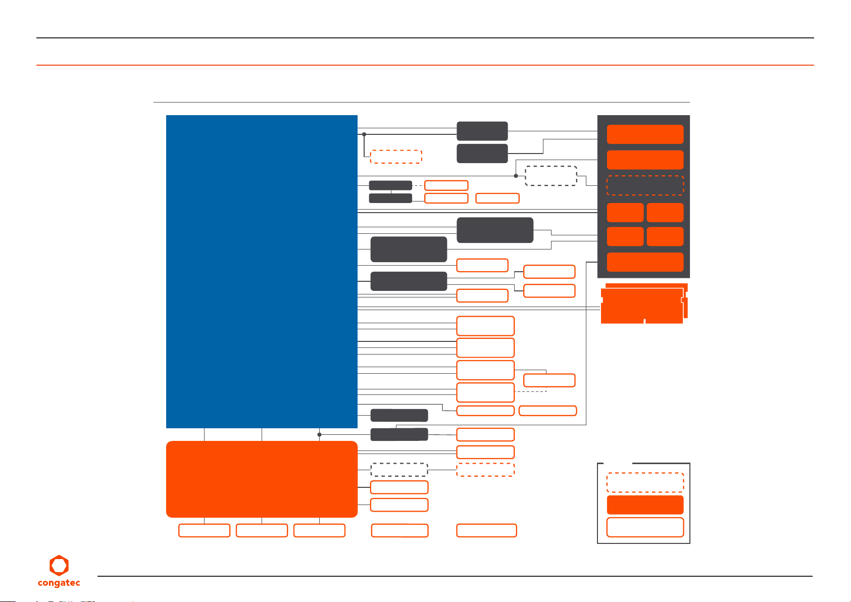
3 Block Diagram
conga-JC370
8th Gen. Intel® Core
“Whiskey Lake”
SOC ULT Processor
3.5” Juke Single Board Computer
USB 3.1 Gen 2
DP2
internal DP
DP1
eDP
2x USB 3.1 Gen 2
PCIe
™
MNGMT LPCPECI
SML
PCIe
HDA
2x USB 2.0
DDR4
SATA
PCIe x4
PCIe
CNVio
USB 2.0
PCIe
USB 2.0
PCIe/SATA
USB 2.0
SATA 6G
SPI
MUX
eDP to LVDS
Ethernet 1Gb
CODEC ALC888
TPM
LPC UART
DP / USB MUX
USB PD
eDP
LVDS Backlight
Ethernet 1Gb
Case Open
2x USB 2.0
M.2 2280
Key-M
M.2 2230
Key-E
M.2 2242/3042
Key-B
miniPCIe
Full/Half
SATA SATA Power
RS232/422/485
TMDS
HPout/MIC
LINEout/DMIC
SIM Card
USB-C
DP++
HDMI
USB 3.1
Gen 2
GbE GbE
RS232/422/485
2x DDR4 2400
SO-DIMM
up to 32 GB each
USB 3.1
Gen 2
2x RS232
congatec
Board
Controller
th
Generation
5
Front Panel SMB/I2C FAN 4-Pin
CAN Controller
GPIO 0-7
MNGMT/GPIO 8-15
RTC Battery Socket DC-In 12-24V
CAN
Legend
Optional
External I/O
Internal I/O
Copyright © 2019 congatec AG JCWLm10 18/55
Page 19
4 Cooling Solution
The conga-JC370 supports the cooling solutions listed in the table below. The dimensions of the cooling solutions are shown in the sub-sections.
All measurements are in millimeters.
Table 10 Cooling Solution Variants
Cooling Solution Part No. Description
1 CSA 054050 Active cooling solution with integrated heat pipes and 2.7 mm bore-hole standoffs
054051 Active cooling solution with integrated heat pipes and M2.5 mm threaded standoffs
2 CSP 054052 Passive cooling solution with integrated heat pipes and 2.7 mm bore-hole standoffs
054053 Passive cooling solution with integrated heat pipes and M2.5 mm threaded standoffs
3 HSP 054054 Heatspreader with integrated heat pipes and 2.7 mm bore-hole standoffs
054055 Heatspreader with integrated heat pipes and M2.5 mm threaded standoffs
Note
1. We recommend a maximum torque of 0.4 Nm for SBC mounting screws and 0.5 Nm for CPU mounting screws.
2. The gap pad material used on congatec heatspreaders may contain silicon oil that can seep out over time depending on the environmental
conditions it is subjected to. For more information about this subject, contact your local congatec sales representative and request the gap
pad material manufacturer’s specification.
Caution
1. The congatec heatspreaders/cooling solutions are tested only within the commercial temperature range of 0° to 60°C. Therefore, if your
application that features a congatec heatspreader/cooling solution operates outside this temperature range, ensure the correct operating
temperature of the SBC is maintained at all times. This may require additional cooling components for your final application’s thermal
solution.
2. For adequate heat dissipation, use the mounting holes on the cooling solution to attach it to the SBC. Apply thread-locking fluid on
the screws if the cooling solution is used in a high shock and/or vibration environment. To prevent the standoff from stripping or crossthreading, use non-threaded carrier board standoffs to mount threaded cooling solutions.
3. For applications that require vertically-mounted cooling solution, use only coolers that secure the thermal stacks with fixing post. Without
the fixing post feature, the thermal stacks may move.
4. Do not exceed the recommended maximum torque. Doing so may damage the SBC.
Copyright © 2019 congatec AG JCWLm10 19/55
Page 20
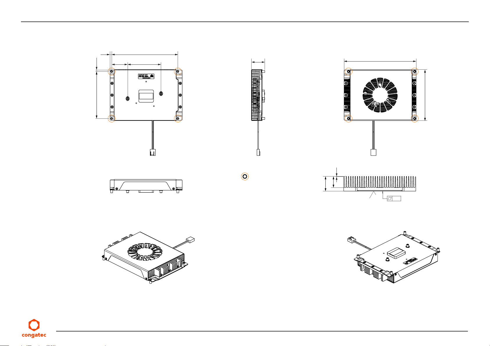
4.1 CSA Dimensions
3.15
95.2
3.2
133.9
67.632.35
27.3
M2.5 x 8 mm
threaded standoff
for threaded version
or
ø2.7 x 8 mm
non-threaded standoff
for borehole version
146
103.6
0.6
16
21
0.8
0.05
Copyright © 2019 congatec AG JCWLm10 20/55
Page 21
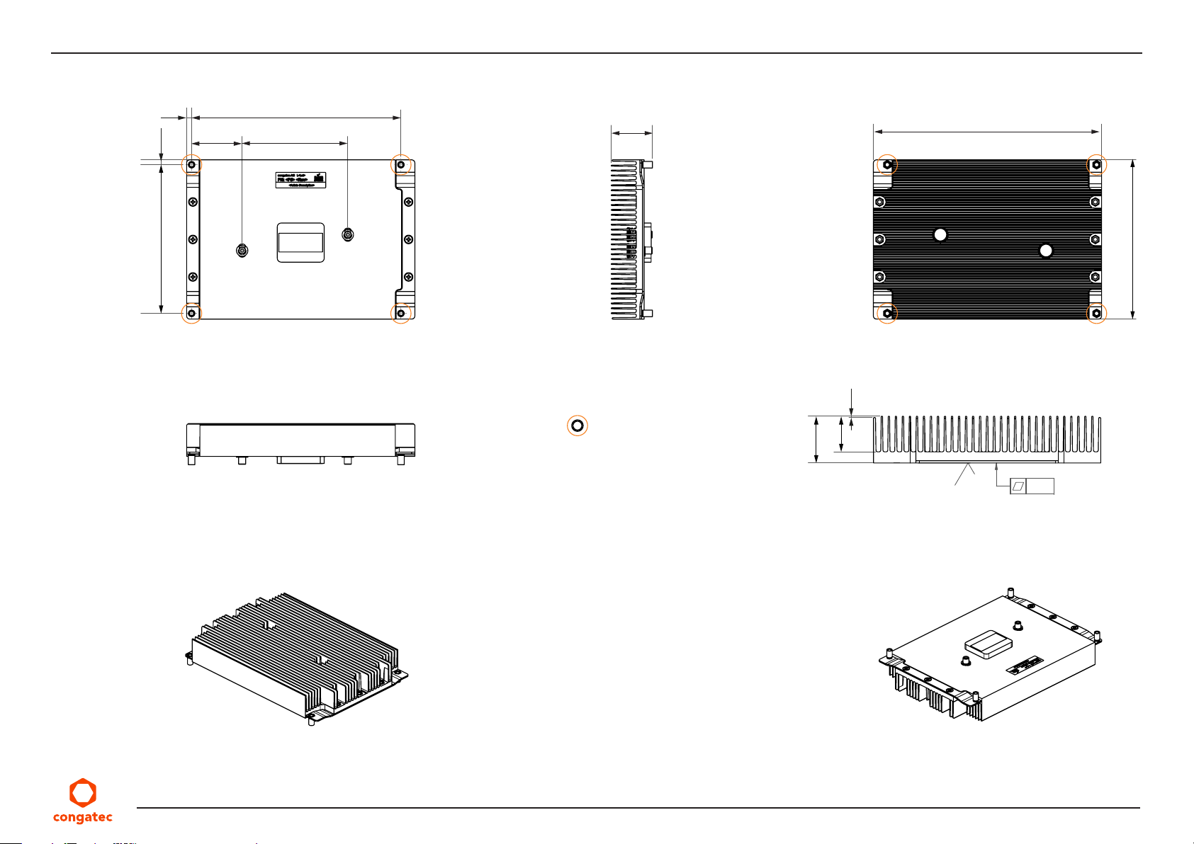
4.2 CSP Dimensions
3.15
95.2
3.2
32.35
133.9
67.6
26.3
M2.5 x 8 mm
threaded standoff
for threaded version
or
ø2.7 x 8 mm
non-threaded standoff
for borehole version
146
102
0.6
16
21
0.8
0.05
Copyright © 2019 congatec AG JCWLm10 21/55
Page 22
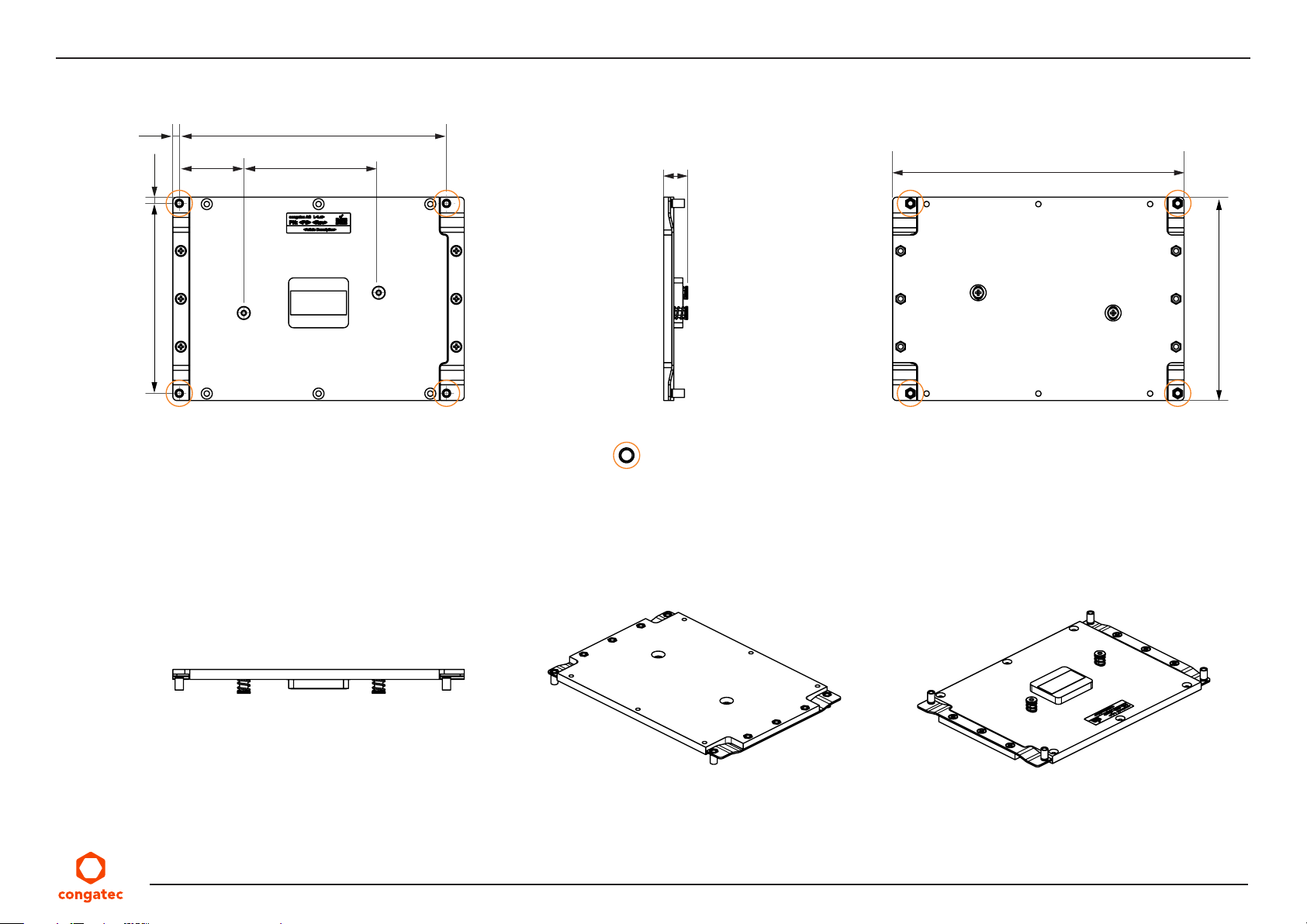
4.3 HSP Dimensions
3.2
95.2
3.15
32.35
133.9
67.6
12
M2.5 x 8 mm
threaded standoff
for threaded version
or
ø2.7 x 8 mm
non-threaded standoff
for borehole version
146
102
Copyright © 2019 congatec AG JCWLm10 22/55
Page 23
5 Connector Description
5.1 Power Supply Connectors
The conga-JC370 provides a 4-pin Mini-Fit connector. The power input is protected by a 15 A non-resettable fuse. Alternatively, the congaJC370 can be powered by USB Type-C.
Note
The conga-JC370 turns on immediately power is supplied. To change this default setting, enter the BIOS setup menu under “Boot Settings
Configuration” and set the “Power Loss Control” to “Remain OFF”.
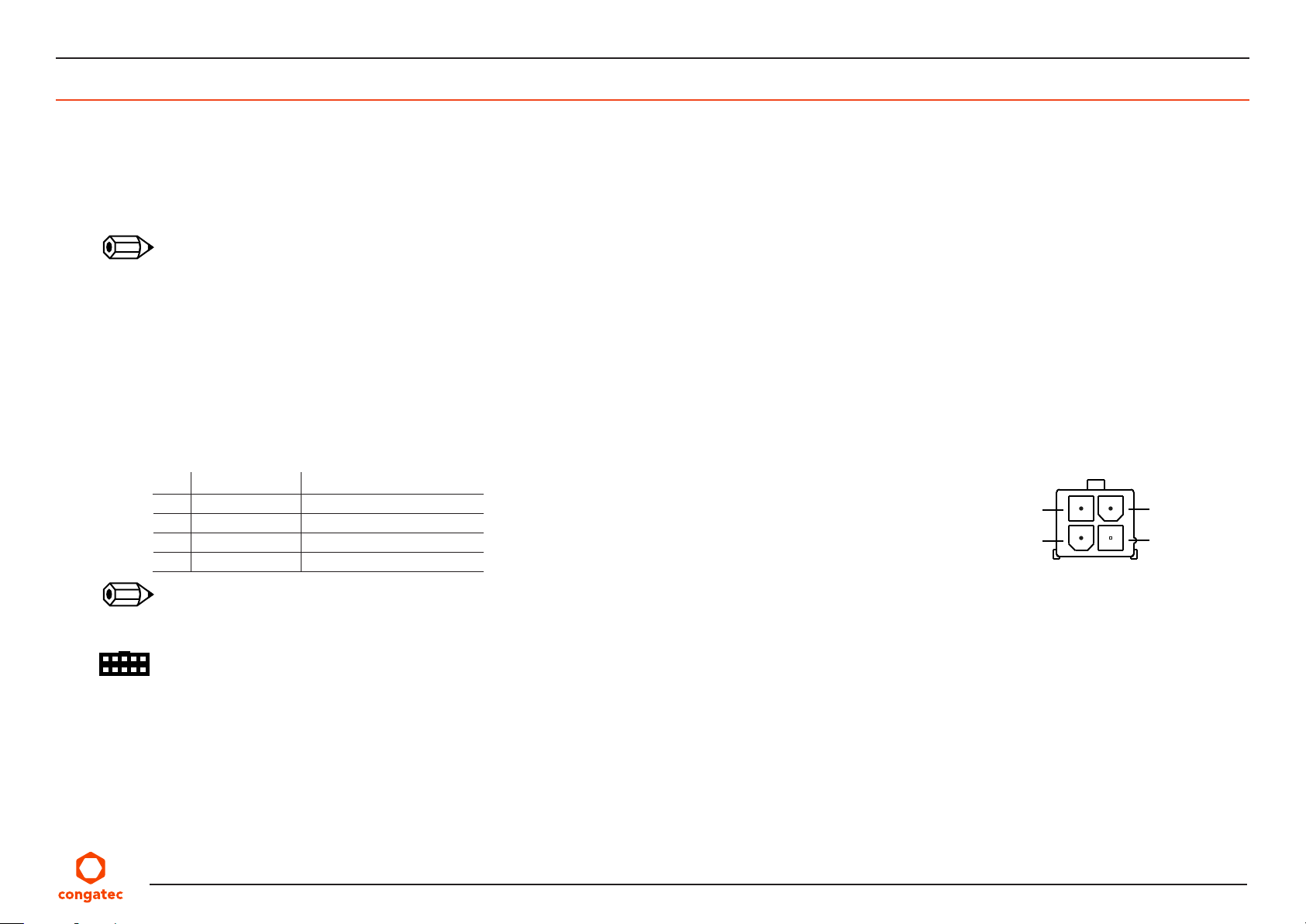
5.1.1 Mini-Fit 4-Pin Connector
The conga-JC370 provides an internal 4-pin Mini-Fit connector with voltage protection.
Table 11 Connector X34 Pinout Description
Pin Signal Description
1 GND Ground
2 GND Ground
3
+12 V–24 V Power supply +12–24 V
4 +12 V–24 V Power supply +12–24 V
X34
4
2
3
1
Note
The conga-JC370 offers a right-angle, 4-pin Mini-Fit connector via assembly option.
Connector Type
X34 : 2 x 2-pin, 4.2 mm pitch Mini-Fit connector (Molex 87427-0442)
Possible Mating Connector: Molex 39012040
Copyright © 2019 congatec AG JCWLm10 23/55
Page 24
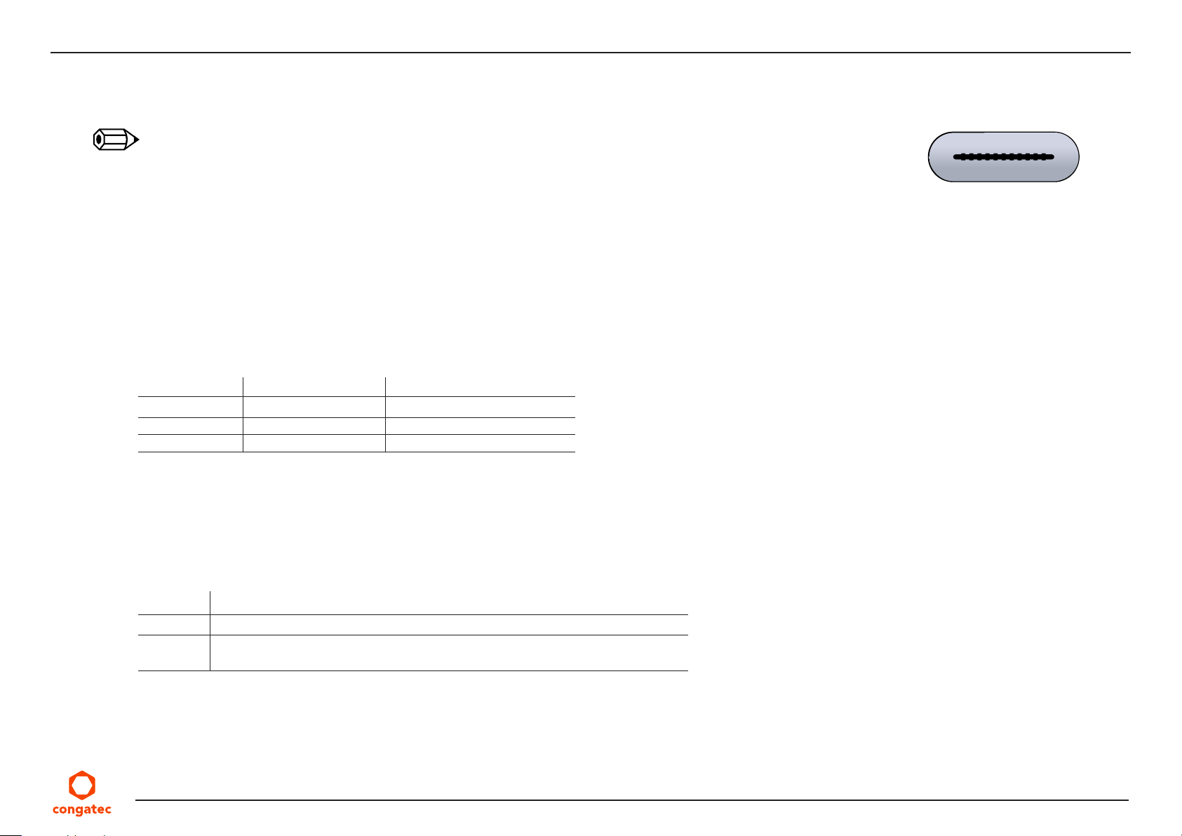
5.1.2 USB Type-C Port
The USB Type-C port on the conga-JC370 supports power sink of 12–20 V at 3–5 A.
Note
1. The conga-JC370 will not turn on if the USB Type-C adapter provides less than 12 V or 3 A.
2. Do not use a power adapter with less than 60 W rating
5.1.3 Power Status LEDs
The LED D57 shows the power state of the conga-JC370 as described in the table below. Optionally, you can connect an LED to pins 9 and 10
of connector X4 for power state indication (see section 5.12 “Front Panel Header”).
Table 12 D57 LED States
LED Status ACPI State Description
Steady red
Steady green S0 System on and running
Steady yellow S3 Suspend to RAM (sleep)
S5 Soft-off
5.1.4 Power-On Control Jumper
X19
The conga-JC370 provides jumper JP2 for controlling the power-on control feature.
Table 13 Auto Power-On Control
Jumper Configuration
1-2 Enables auto power-on control regardless of the BIOS settings
Open Power-on feature is controlled via the BIOS setup menu.
The power-on control is enabled in the BIOS setup menu by default
Copyright © 2019 congatec AG JCWLm10 24/55
Page 25
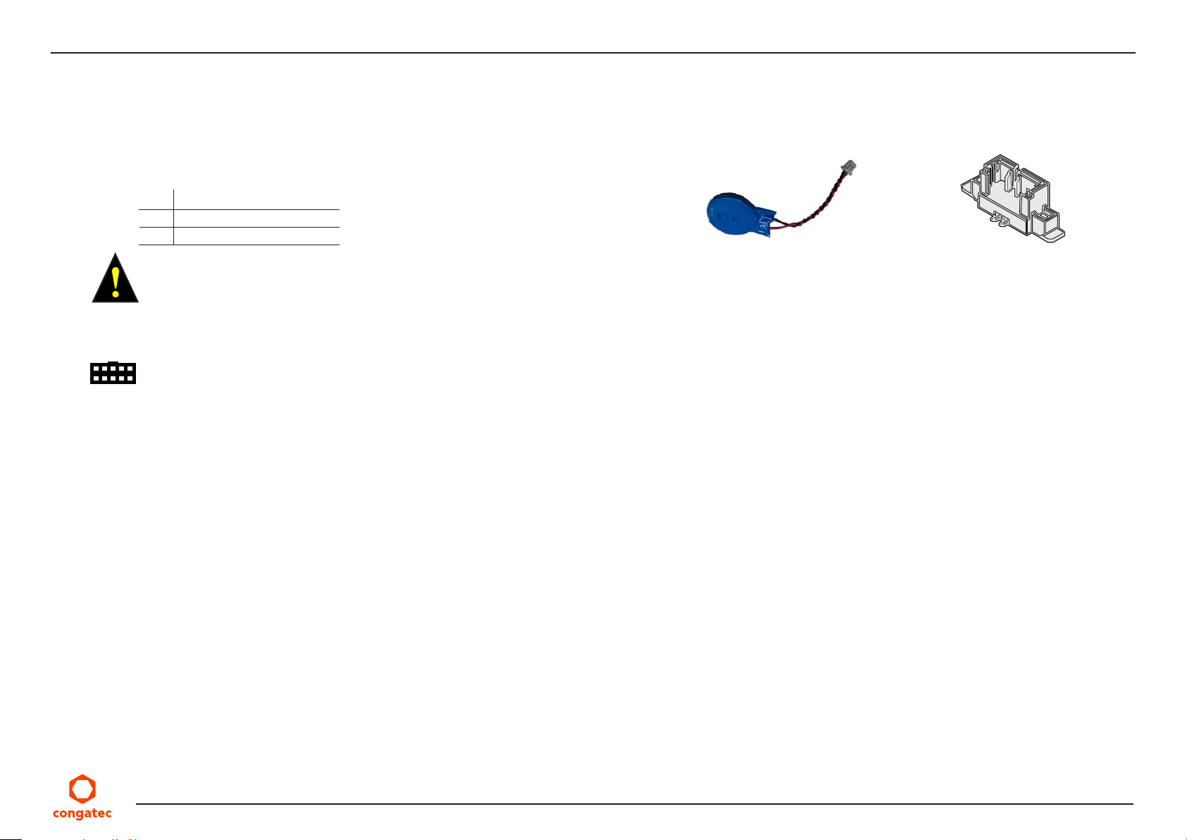
5.1.5 CMOS Battery Header
The conga-JC370 provides a CR2032 CMOS battery which is connected to pin header X36. The battery supplies power to maintain the CMOS
settings and real time clock.
Table 14 X36 Pin Header
Pin Description
1 RTC power (+3V)
2 Ground reference
Warning
Danger of explosion if battery is incorrectly replaced. Replace only with same or equivalent type recommended by the manufacturer. Dispose
of used batteries according to the manufacturer’s instructions.
Connector Type
X36 : 2-pin, 1.25 mm pitch Molex PicoBlade header (Molex 0533980271)
Battery
X36
Copyright © 2019 congatec AG JCWLm10 25/55
Page 26
5.2 Extension Sockets
The conga-JC370 provides the following extension sockets:
• Mini Card—full or half size (PCIe x1/SATA/USB)
• M.2 key B, type 2242/3042 (PCIe x2/USB/SIM)
• M.2 key E, type 2230 (PCIe x1/USB/CNVi)
• M.2 key M, type 2280 (PCIe x4/SATA/Intel® Optane™)
5.2.1 Mini Card Socket
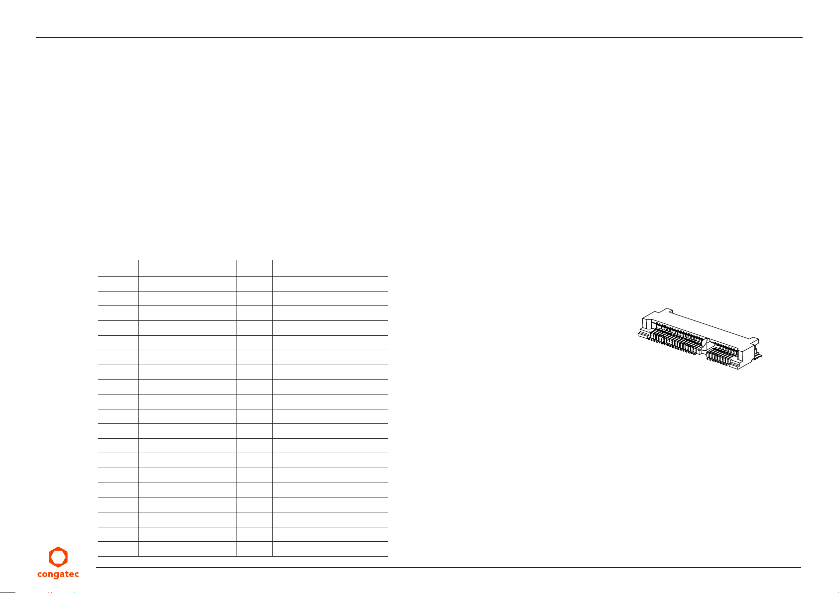
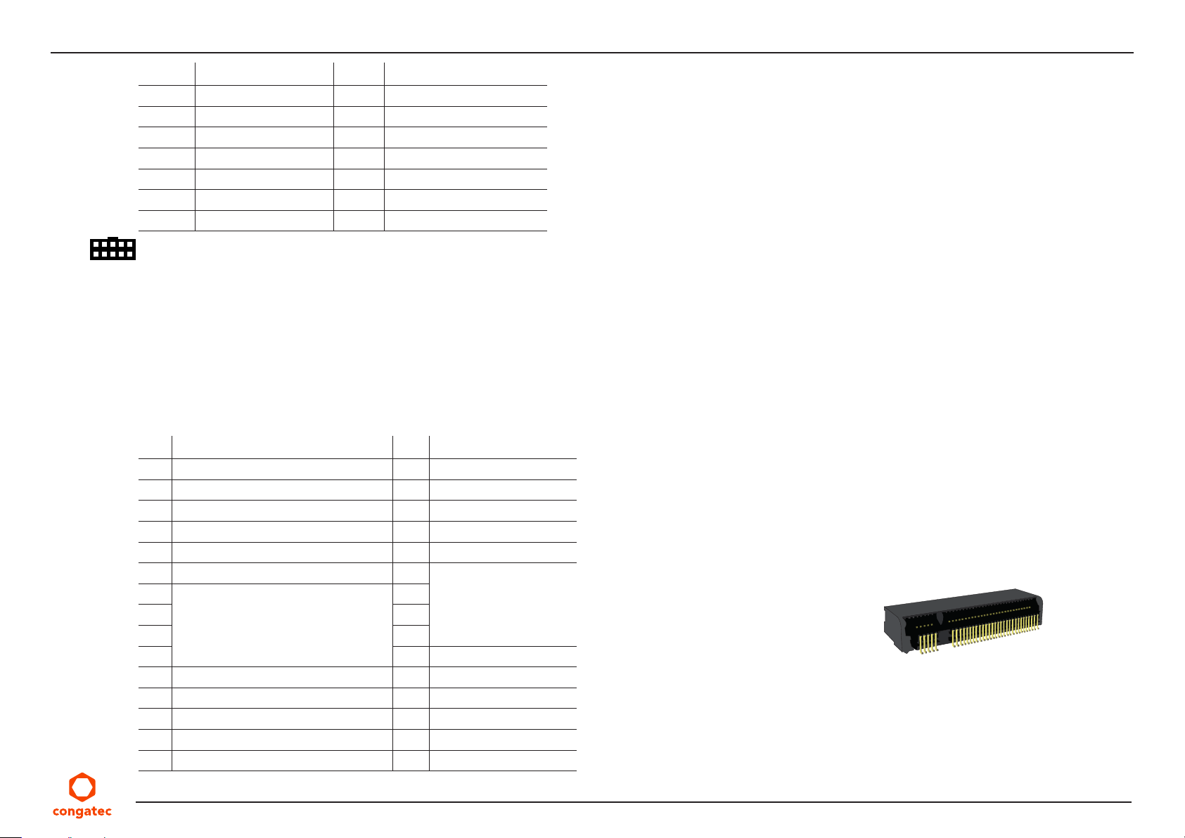
The conga-JC370 provides a Mini Card socket (X26). The socket supports full or half size PCIe, SATA or USB 2.0 cards.
Table 15 X26 Pinout Description
Pin Signal Pin Signal
1 WAKE# 2 +3.3 V
3 N.C 4 GND
5 N.C 6
7 CLKREQ# 8 N.C
9 GND 10 N.C
11 REFCLK- 12 N.C
13 REFCLK+ 14 N.C
15 GND 16 N.C
17 N.C 18 GND
19 N.C 20 W_DISABLE#
21 GND 22 PERST#
23 PERn0 24
25 PERp0 26 GND
27 GND 28
29 GND 30 SMB_CLK
31 PETn0 32 SMB_DATA
33 PETp0 34 GND
35 GND 36 USB_D-
37 GND 38 USB_D+
+1.5 V
+3.3 V
+1.5 V
X26
Copyright © 2019 congatec AG JCWLm10 26/55
Page 27
Pin Signal Pin Signal
39 +3.3 V 40 GND
41
43 PCIe/SATA detection 44 N.C
45 N.C 46 N.C
47 N.C 48
49 N.C 50 GND
51 N.C 52
+3.3 V 42 N.C
Connector Type
X26: Standard Mini Card socket (full size or half size)
5.2.2 M.2 Key B Socket
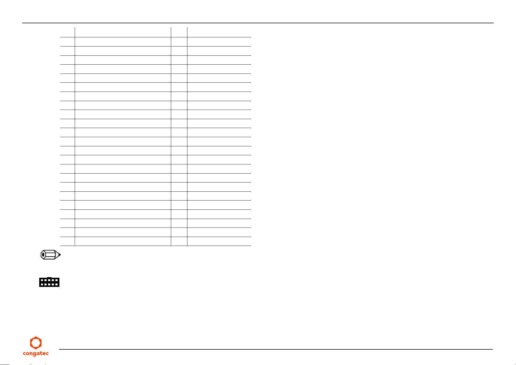
The conga-JC370 provides an M.2 key B, type 2242/3042 socket (X24) for connecting a PCIe or USB (WWAN) card.
Table 16 X24 Pinout Description
Pin Signal Pin Signal
1 N.C 2 +3.3V
3 GND 4 +3.3V
5 GND 6 FULL_CARD_PWROFF#
7 USB_D+ 8 W_DISABLE_1#
9 USB_D- 10 N.C
11 GND 12
13
15 16
Key
17 18
19 20 N.C
21 N.C 22 N.C
23 WoWWAN# 24 N.C
25 N.C 26 W_DISABLE_2#
27 GND 28 N.C
29 PER1- 30 UIM_RESET
+1.5 V
+3.3 V
14
X24
Key
Copyright © 2019 congatec AG JCWLm10 27/55
Page 28
Pin Signal Pin Signal
31 PER1+ 32 UIM_CLK
33 GND 34 UIM_DATA
35 PET1- 36 UIM_PWR
37 PET1+ 38 N.C
39 GND 40 N.C
41 PER0- 42 N.C
43 PER0+ 44 N.C
45 GND 46 N.C
47 PET0- 48 N.C
49 PET0+ 50 PERST#
51 GND 52 CLKREQ#
53 REFCLK- 54 PEWAKE#
55 REFCLK+ 56 N.C
57 GND 58 N.C
59 N.C 60 COEX3
61 N.C 62 COEX2
63 N.C 64 COEX1
65 N.C 66 N.C
67 RESET# 68 N.C
69 N.C 70
71 GND 72 +3.3 V
73 GND 74 +3.3 V
75 N.C
+3.3 V
Note
The micro-SIM card slot is connected to the UIM interface by default.
Connector Type
X24: Standard PCIe M.2 key B socket
Copyright © 2019 congatec AG JCWLm10 28/55
Page 29
5.2.3 M.2 Key E Socket
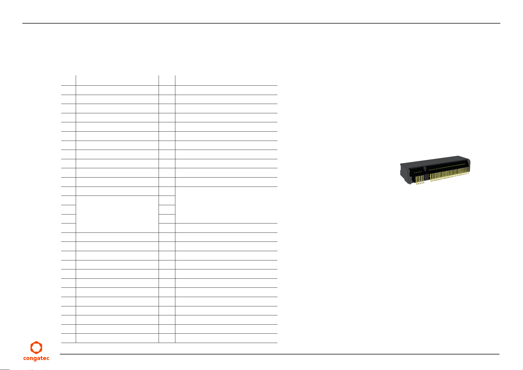
The conga-JC370 provides an M.2 key E, type 2230 socket (X27) for connecting a PCIe, USB or Intel® CNVi WLAN card.
Table 17 X27 Pinout Description
Pin Signal Pin Signal
1 GND 2 +3.3 V
3 USB_D+ 4 +3.3 V
5 USB_D- 6 LED#1
7 GND 8 PCM_CLK/I2S_SCK
9 CNV_WR_D1- 10 PCM_SYNC/I2S_WS
11 CNV_WR_D1+ 12 PCM_IN/I2S_SD_IN
13 GND 14 PCM_OUT/I2S_SD_OUT
15 CNV_WR_D0- 16 LED#2
17 CNV_WR_D0+ 18 GND
19 GND 20 BT_WAKE#
21 CNV_WR_CLK- 22 CNV_BRI_RSP
23 CNV_WR_CLK+ 24
25
27 28
Key
29 30
31 32 CNV_RGI_DT
33 GND 34 CNV_RGI_RSP
35 PET0+ 36 CNV_BRI_DT
37 PET0- 38 CL_RST#
39 GND 40 CL_DATA
41 PER0+ 42 CL_CLK
43 PER0- 44 COEX3
45 GND 46 COEX2
47 REFCLK0+ 48 COEX1
49 REFCLK0- 50 SUSCLK
51 GND 52 PERST#0
53 CLKREQ0# 54 RSVD/W_DISABLE#2
55 PEWAKE0# 56 W_DISABLE#1
26
X27
Key
Copyright © 2019 congatec AG JCWLm10 29/55
Page 30
Pin Signal Pin Signal
57 GND 58 N.C
59 CNV_WT_D1- 60 N.C
61 CNV_WT_D1+ 62 N.C
63 GND 64 CNV_REFCLK
65 CNV_WT_D0- 66 PERST#1
67 CNV_WT_D0+ 68 N.C
69 GND 70 N.C
71 CNV_WT_CLK- 72
73 CNV_WT_CLK+ 74 +3.3 V
75 GND
Connector Type
X27: Standard PCIe M.2 key E socket
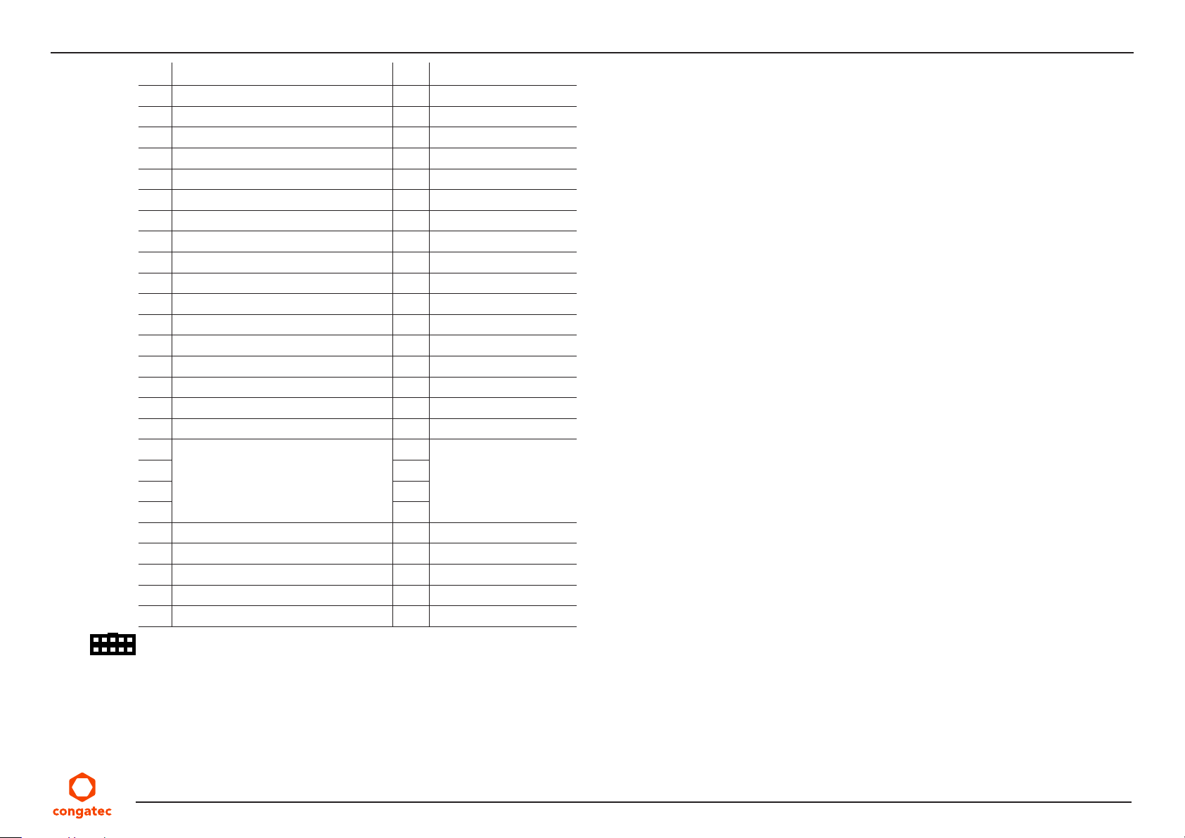
5.2.4 M.2 Key M Socket
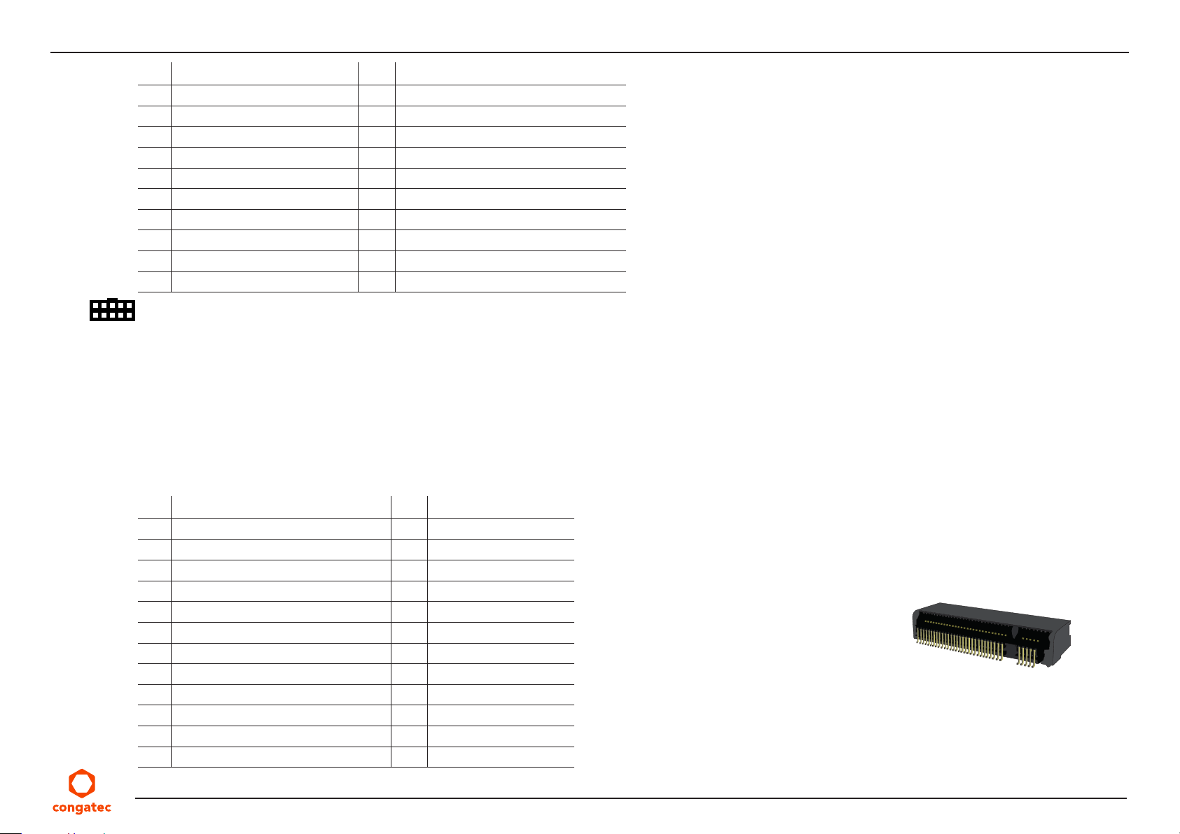
The conga-JC370 provides an M.2 key M, type 2280 socket (X28) for connecting a PCIe x4 SSD (NVMe), SATA SSD or Intel® Optane™.
Table 18 X28 Pinout Description
+3.3 V
Pin Signal Pin Signal
1 GND 2 +3.3 V
3 GND 4 +3.3 V
5 PER3- 6 N.C
7 PER3+ 8 N.C
9 GND 10 N.C
11 PET3- 12
13 PET3+ 14 +3.3 V
15 GND 16 +3.3 V
17 PER2- 18 +3.3 V
19 PER2+ 20 N.C
21 GND 22 N.C
23 PET2- 24 N.C
Copyright © 2019 congatec AG JCWLm10 30/55
+3.3 V
X28
Page 31
Pin Signal Pin Signal
25 PET2+ 26 N.C
27 GND 28 N.C
29 PER1- 30 N.C
31 PER1+ 32 N.C
33 GND 34 N.C
35 PET1- 36 N.C
37 PET1+ 38 SATA_DEVSLP
39 GND 40 N.C
41 PER0-/SATA_B+ 42 N.C
43 PER0+/SATA_B- 44 N.C
45 GND 46 N.C
47 PET0-/SATA_A- 48 N.C
49 PET0+/SATA_A+ 50 PERST#
51 GND 52 CLKREQ#
53 REFCLK- 54 N.C
55 REFCLK+ 56 N.C
57 GND 58 N.C
59
61 62
Key
63 64
65 66
67 N.C 68 N.C
69 PEDET 70
71 GND 72 +3.3 V
73 GND 74 +3.3 V
75 GND
60
Key
+3.3 V
Connector Type
X28: Standard PCIe M.2 key M socket
Copyright © 2019 congatec AG JCWLm10 31/55
Page 32
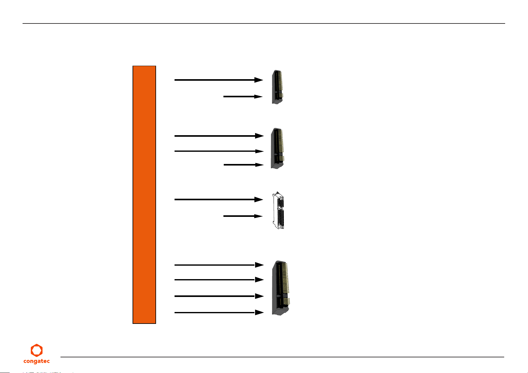
5.2.5 PCI Express Routing
The diagram below shows how the PCIe lanes are routed to the expansion sockets.
X27—M.2 key E (PCIe x1)
PCIe Lane 6
USB 2.0 Signals
X24—M.2 key B (PCIe x2)
PCIe Lane 9
PCIe Lane 10
USB 2.0 Signals
X26—mini PCIe (PCIe x1)
PCIe Lane 12 or SATA 1
USB 2.0 Signals
PCIe Lane Mapping
PCIe Lane 13
PCIe Lane 14
PCIe Lane 15
PCIe Lane 16 or SATA 2
Copyright © 2019 congatec AG JCWLm10 32/55
X28—M.2 key M (PCIe x4 )
Page 33
5.3 Display Interfaces
The conga-JC370 supports three independent displays—a DP++, a USB Type-C and an LVDS or eDP panel. The graphic engine supports
DirectX 12, OpenGL 4.5, OpenCL 2.1, Intel QuickSync and Clear Video Technology HD, hybrid graphics.
Optionally, the conga-JC370 can support HDMI instead of DP++, and iDP instead of USB Type-C.
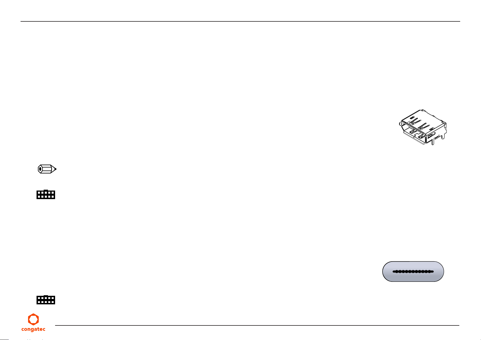
5.3.1 Display Port
The conga-JC370 provides a DP++ port (X17). The port supports:
• VESA DisplayPort Standard 1.2
• data rate of 5.4 GT/s with four data lanes
• resolutions up to 4096 x 2304 at 60 Hz
• audio formats such as AC-3 Dolby Digital, Dolby Digital Plus, DTS-HD, LPCM, Dolby TrueHD, DTS-HD Master audio
• HDMI and DVI with appropriate adapter
Note
The conga-JC370 supports resolutions up to 4k only if you populate both memory sockets with modules of same size and speed.
Connector Type
X17: Standard DisplayPort connector
5.3.2 USB Type-C Alternate Mode
The conga-JC370 provides a USB Type-C port (X19) for connecting USB or DisplayPort (alternate mode). The port supports:
• USB 3.1 Gen. 2
X17
X19
• VESA DisplayPort Standard 1.2
• resolutions up to 4096 x 2304 at 60 Hz
• power delivery of up to 5 V @ 3 A
Connector Type
X19: Standard USB Type-C port
Copyright © 2019 congatec AG JCWLm10 33/55
Page 34
5.3.3 LVDS/eDP Header
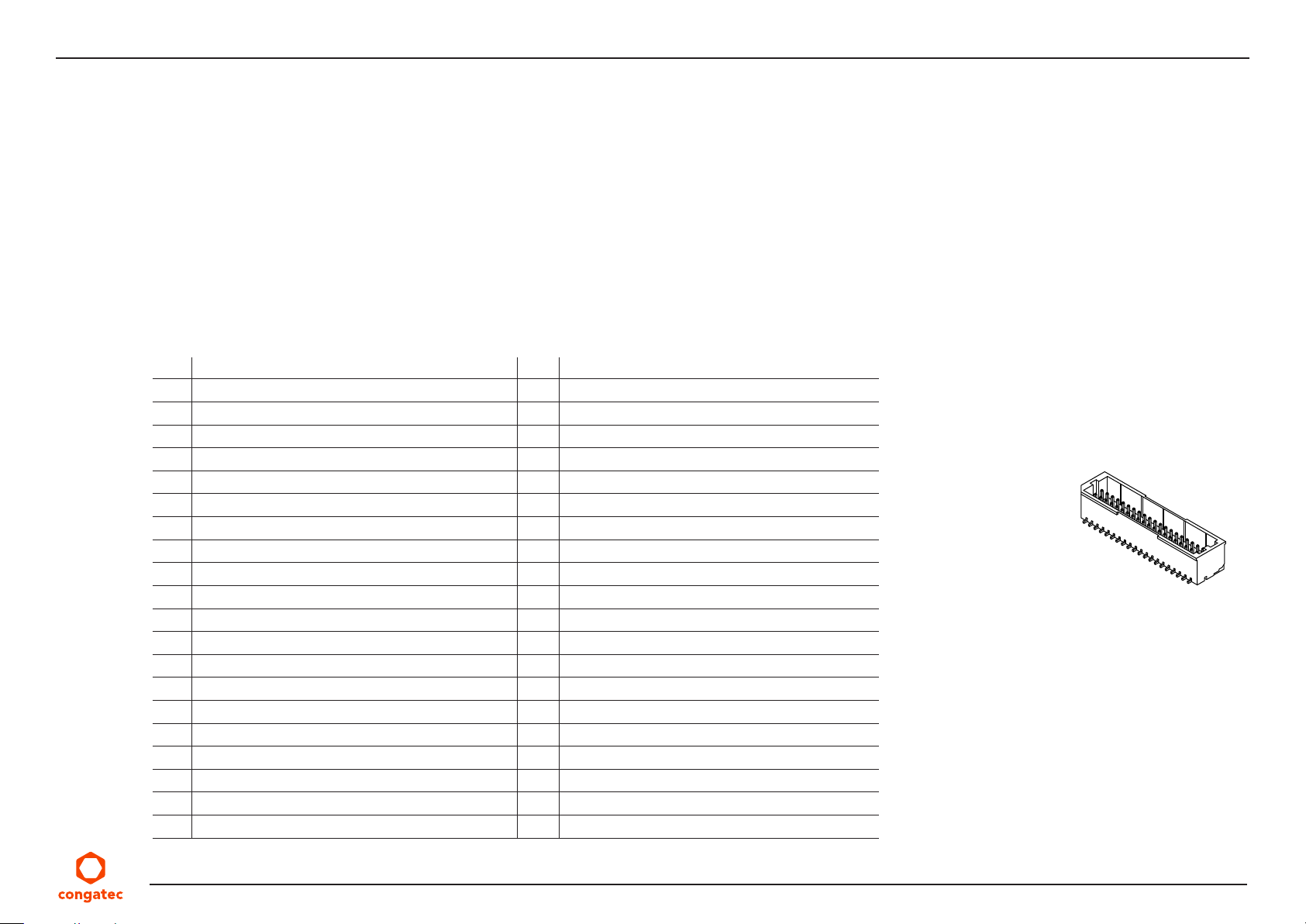
The conga-JC370 provides an LVDS interface on connector X15 . The interface is located on the top side of the SBC and supports the following:
• 18 or 24 bit, single or dual channel
• selectable panel voltage
• VESA or JEIDA data mapping
• ANSI/TIA/EIA-644-1-2001 standard
• automatic panel detection (EDID)
• resolution up to 1920 x 1200 in dual LVDS mode
Table 19 Connector X15 Pinout Description
Pin Signal Pin Signal
1 VCC (fuse with 1 A hold current) 2 VCC (fuse with 1.5 A hold current at 25ºC)
3 VCC (fuse with 1 A hold current) 4 VCC (fuse with 1.5 A hold current at 25ºC)
5 VCC_EDID (+3.3 V) 6 GND
7 EDID_CLK 8 EDID_DATA
9 VDDEN 10 eDP_HPD (not connected if LVDS is supported )
11 GND 12 GND
13 LVDS_ODD_TX0N / eDP_TX0N 14 LVDS_ODD_TX1N / eDP_TX1N
15 LVDS_ODD_TX0P / eDP_TX0P 16 LVDS_ODD_TX1P / eDP_TX1P
17 GND 18 GND
19 LVDS_ODD_TX2N / eDP_TX2N 20 LVDS_ODD_CLKN / eDP_AUXN
21 LVDS_ODD_TX2P / eDP_TX2P 22 LVDS_ODD_CLKP / eDP_AUXP
23 GND 24 GND
25 LVDS_ODD_TX3N / eDP_TX3N 26 LVDS_EVEN_TX0N
27 LVDS_ODD_TX3P / eDP_TX3P 28 LVDS_EVEN_TX0P
29 GND 30 GND
31 LVDS_EVEN_TX1N 32 LVDS_EVEN_TX2N
33 LVDS_EVEN_TX1P 34 LVDS_EVEN_TX2P
35 GND 36 GND
37 LVDS_EVEN_CLKN 38 LVDS_EVEN_TX3N
39 LVDS_EVEN_CLKP 40 LVDS_EVEN_TX3P
X15
Copyright © 2019 congatec AG JCWLm10 34/55
Page 35
Note
1. EDID signals and VDDEN output are 3.3 V.
2. The maximum output current for LCD and backlight power rails is 1.5 A.
3. Use ODD pins for single channel LVDS panel.
4. eDP support via assembly option
Connector Type
X15: 40-pin, 1 mm pitch header (JST BM40B-SRDS-G-TF)
Possible Mating Connector: JST SHDR-40V-S-B
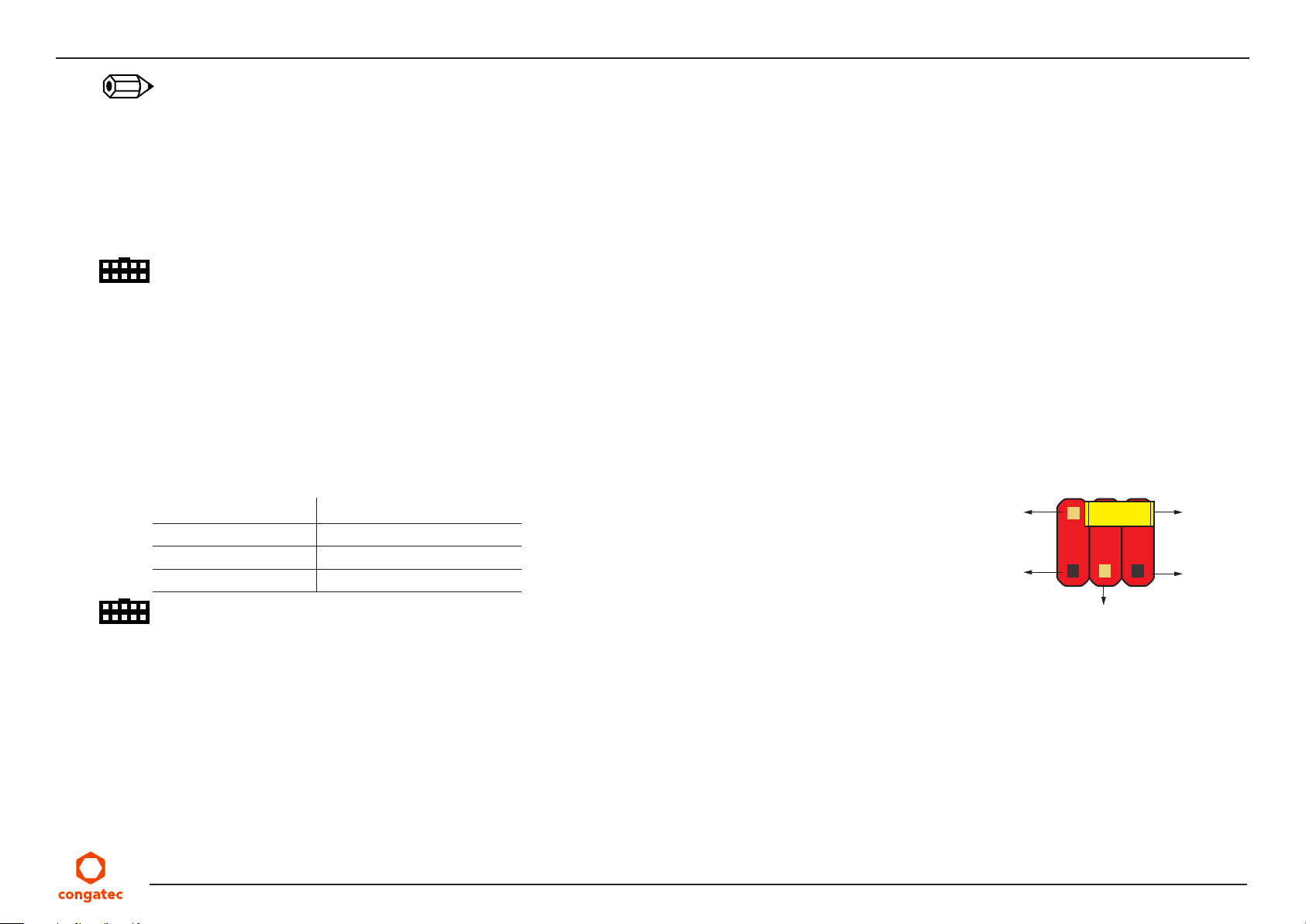
5.3.3.1 Panel Voltage Selection Jumper
The conga-JC370 supports 3.3 V, 5 V and 12 V LCD panels. Use jumper JP1 to set the panel voltage.
Table 20 JP1 Pinout Description
Jumper Panel Voltage
2-4 5 V
3-4 12 V
4-6 3.3 V (default)
Connector Type
Pin 2
No Pin
JP1
Pin 6
No Pin
Pin 3
JP1: 2.54 mm, 2 x 3-pin header (without pins 1 and 5)
Copyright © 2019 congatec AG JCWLm10 35/55
Page 36
5.3.3.2 Backlight Control Voltage Selection Jumper
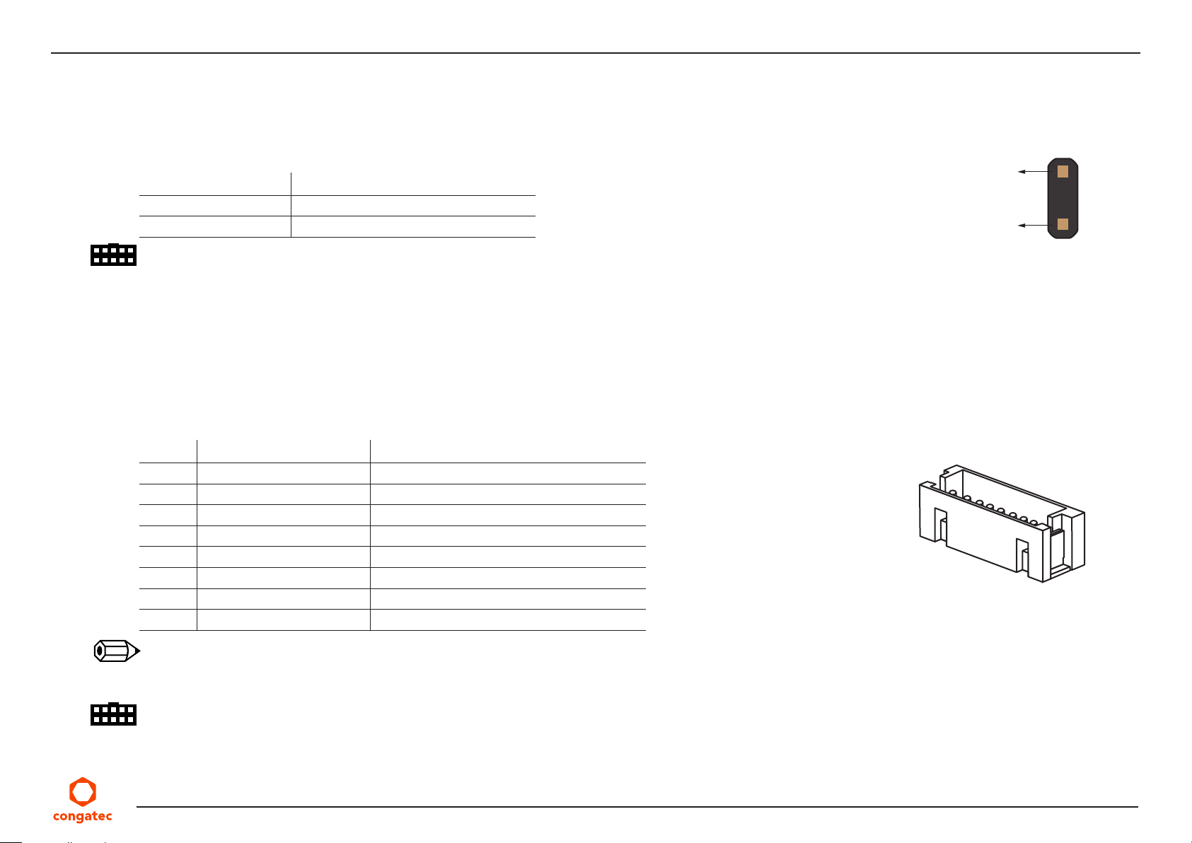
The conga-JC370 supports LCD backlight control signals with 3.3 V or 5 V. Use jumper JP3 to select the voltage level.
Table 21 JP3 Pinout Description
Jumper Backlight Control Voltage
1-2 5 V (default)
Open 3.3 V
Connector Type
JP3: 2.54 mm, 1 x 2-pin header
5.3.3.3 Backlight Power Header
The conga-JC370 provides header X14. The maximum hold current is 1.5 A.
Table 22 Connector X14 Pinout Description
Pin Signal Name Description
1 +12V 12 V backlight inverter power (1.5 A fuse)
2 +12V 12 V backlight inverter power (1.5 A fuse)
3 GND Backlight ground
4 GND Backlight ground
5 eDP_LVDS_BKLT_EN Backlight enable
6 eDP_LVDS_BKLT_CTRL Backlight control
7 +5V 5 V backlight inverter power (1.5 A fuse)
8 +5V 5 V backlight inverter power (1.5 A fuse)
JP3
Pin 2
Pin 1
X14
Note
The backlight enable and control signals are 3.3 V or 5 V output signals. Select the voltage level with jumper JP3.
Connector Type
X14: 2 mm, 8-pin Crimp style connector (JST B8B-ZR-SM4-TF)
Possible Mating Connector: JST ZHR-8
Copyright © 2019 congatec AG JCWLm10 36/55
Page 37
5.4 USB Connectors
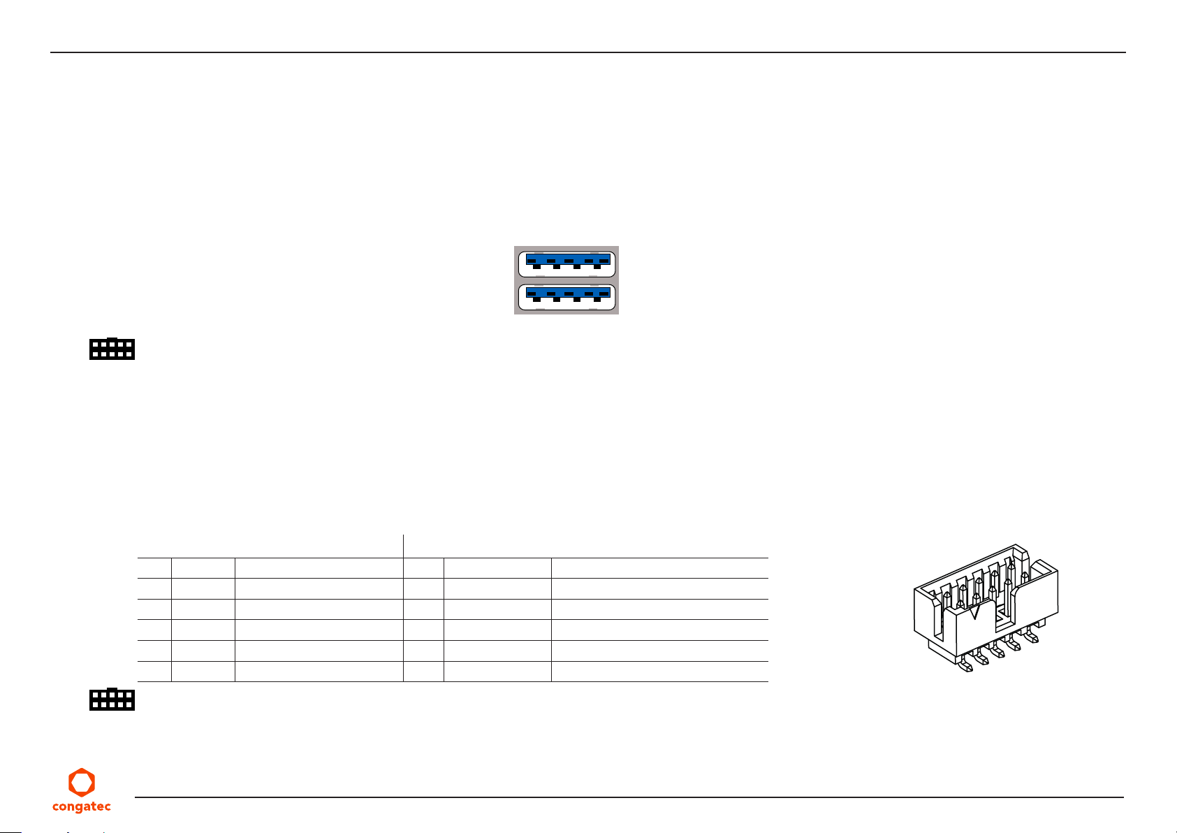
The conga-JC370 provides two USB 3.1 Gen. 2 Type-A ports, two USB 2.0 ports and one USB Type-C port.
5.4.1 USB 3.1 Gen. 2 Port
The conga-JC370 provides two USB 3.1 Gen. 2 ports on connector X20. Each port supports a maximum current of 1 A.
Connector Type
X20: Dual-stacked USB 3.0 type A connector
5.4.2 USB 2.0 Header
The conga-JC370 provides two USB 2.0 ports via header X21. Each port supports a maximum current of 0.5 A.
X20
15
10 11 12 13
6
1 2 3 4
14161718
Port 2
5789
Port 1
Table 23 Connector X21 Pinout Description
USB Port 7 USB Port 8
Pin Signal Description Pin Signal Description
+5 V +5 V supply 2 +5 V +5 V supply
1
3 USB7- USB Port 7, Data- 4 USB8- USB Port 8, Data-
5 USB7+ USB Port 7, Data+ 6 USB8+ USB Port 8, Data+
7 GND Ground 8 GND Ground
9 SHLD Cable shield 10 SHLD Cable shield
X21
Connector Type
X21: 2 mm pitch, 2 x 5-pin shrouded header (Molex 0878321014)
Possible Mating Connector: Molex 511101051
Copyright © 2019 congatec AG JCWLm10 37/55
Page 38
5.4.3 USB Type-C Port
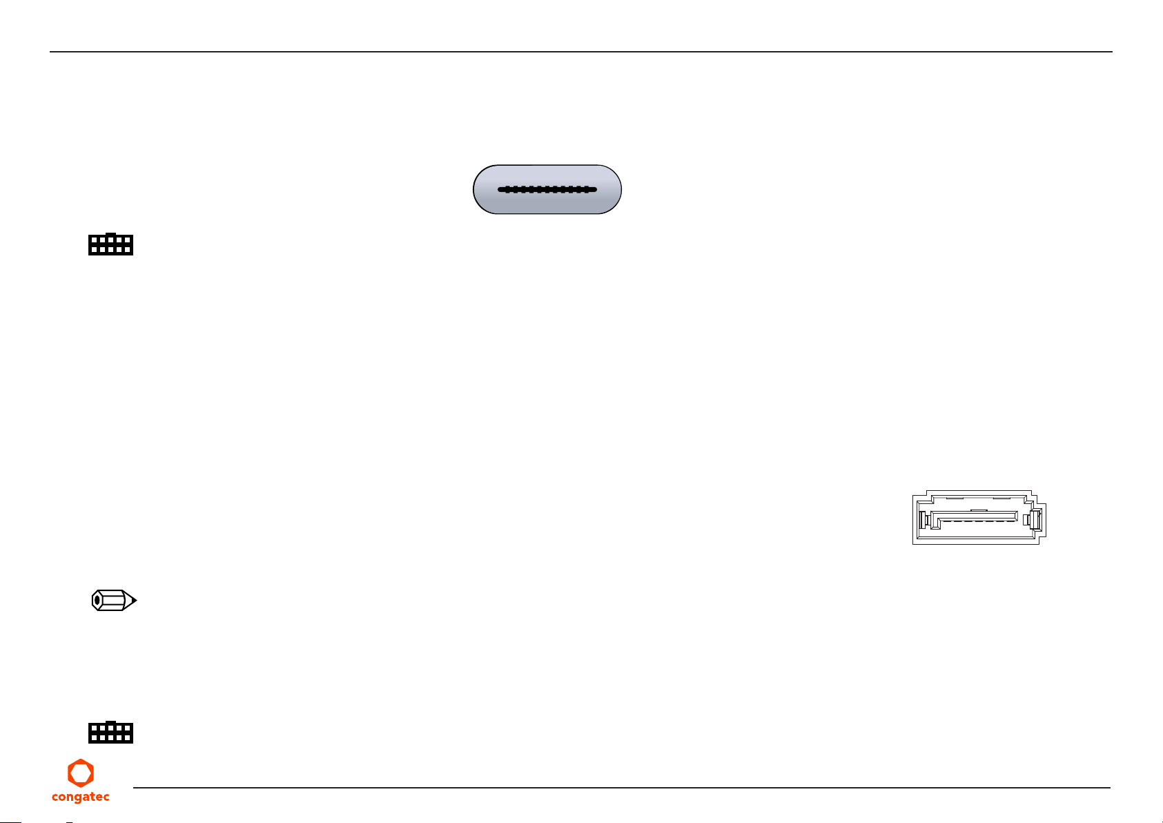
The conga-JC370 provides one USB Type-C port on connector X19. The port supports USB 3.1 Gen. 2, DisplayPort 1.2 and power delivery up
to 5 V @ 3 A.
Connector Type
X19: USB Type-C connector
5.5 SATA Connectors
The conga-JC370 provides a standard SATA 3.0 port, an mSATA/mPCIe socket, an M.2 key M socket and a SATA power header.
5.5.1 Standard SATA Port
The conga-JC370 provides a standard SATA 3.0 port on X29. The port supports:
• SATA, eSATA or SATADOM with appropriate cable
X19
X29
• pin 7 power source for SATADOMs (disabled in the BIOS setup menu by default)
• pin 8 power source for SATADOMs
To show SATA port activity, connect an LED to pin 11 and 12 of the front panel connector X4.
7 6 5 4 3 2 1
Note
1. Enable pin 7 power source in the BIOS setup menu under “Chipset ->Platform Controller Hub -> SATA and RST Configuration -> SATADOM
Power Pin 7” and select “SATADOM”.
2. To use pin 8 power source, disable pin 7 power source in the BIOS setup menu under “Chipset ->Platform Controller Hub -> SATA and
RST Configuration -> SATADOM Power Pin 7” and select “SATA SSD/HDD”.
Connector Type
X29: Standard SATA connector
Copyright © 2019 congatec AG JCWLm10 38/55
Page 39
5.5.2 mSATA Socket
The conga-JC370 provides an mSATA socket (X26) for connecting a SATA or PCIe device. Refer to section 5.2.1 “Mini Card Socket”” for X26
pinout description.
5.5.3 M.2 Key M Socket
The conga-JC370 provides an M.2 key M, type 2280 socket (X28) for connecting a SATA SSD. Refer to section 5.2.4 “M.2 Key M Socket”” for
X28 pinout description.
5.5.4 SATA Power Header
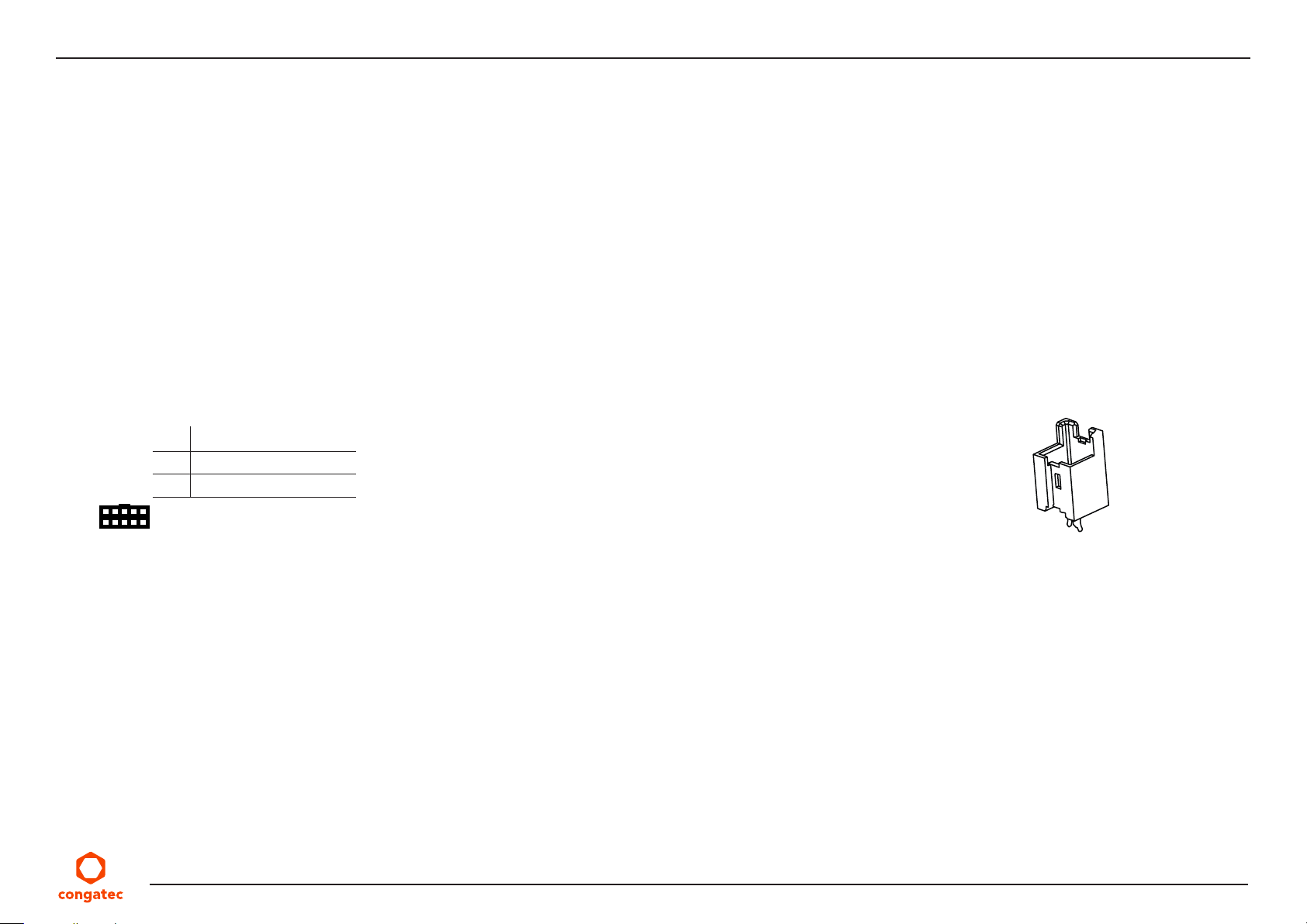
The conga-JC370 provides a 2-pin SATA power header (X30) for 2.5” HDD or SSD. The header supplies 5 V with a maximum current of 1.5 A.
Table 24 X30 Pinout Description.
Pin Signal
1 5 V (maximum 1.5 A)
2 GND
Connector Type
X30: 2.5 mm pitch, 2-pin header (Molex 533750210)
Possible Mating Connector: Molex 511030200
X30
Copyright © 2019 congatec AG JCWLm10 39/55
Page 40
5.6 Ethernet
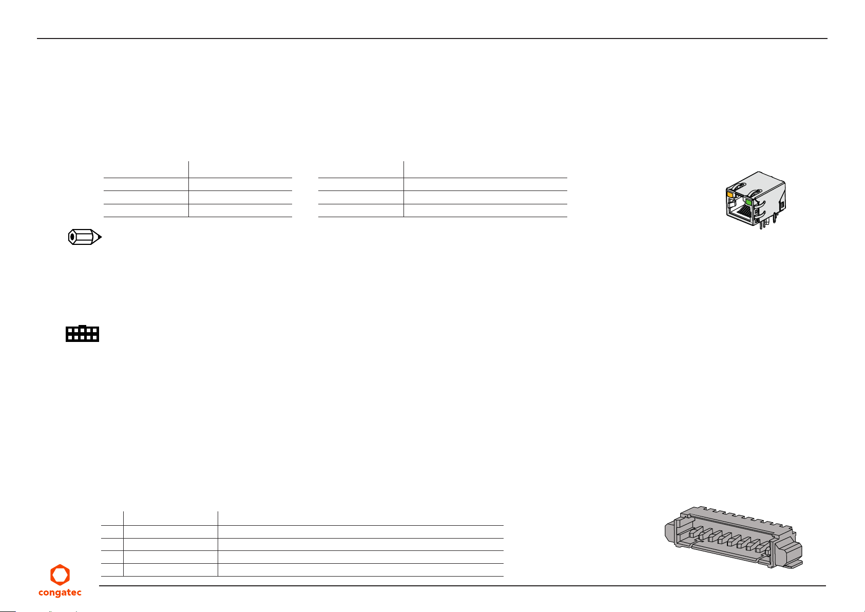
The conga-JC370 provides two Gigabit Ethernet ports (X22 and X23). X22 interface is equipped with Intel i219-LM controller on i7 and i5
variants and with Intel i219-V controller on i3 and Celeron variants.
X23 interface is equipped with Intel i255-LM controller by default but can be equipped with Intel i225-V by assembly option.
Table 25 GbE LED Description
LED Left Side Description
Off 10 Mbps link speed
Green 100 Mbps link speed
Orange 1000 Mbps link speed
Note
1. Only variants with Intel i219-LM support Intel vPro/AMT technology.
2. Only variants with Intel i255-LM support TSN.
3. TSN is supported on only Linux OS
Connector Type
X22/X23
LED Right Side Description
Off No link
Steady On Link established, no activity detected
Blinking Link established, activity detected
X22,X23: 8-pin RJ45 connector with gigabit magnetic and LEDs
5.7 HDA Header
The conga-JC370 features a high definition audio codec (Realtek ALC888S). The codec supports:
• digital MIC and Line-OUT signals on header X31
• headphone-OUT and MIC-IN signals on header X32
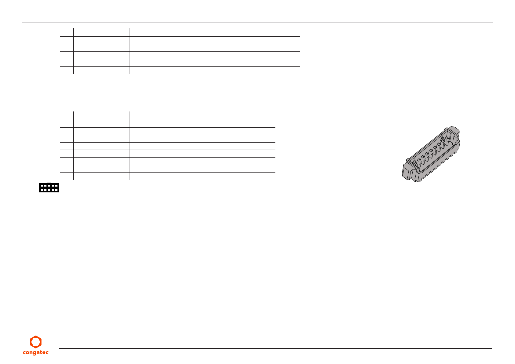
Table 26 X31 Pinout Description
Pin Signal Description
1 FRONT_R Analog front - right channel
2 FRONT_L Analog front - left channel
3 A_GND Analog ground (return path for analog front)
4 SENSE_A Jack detection for analog front output
Copyright © 2019 congatec AG JCWLm10 40/55
X31
Page 41
Pin Signal Description
5 +5V 5 V power supply (protected by 500 mA resetable fuse)
6 +3.3V 3.3 V power supply for DMIC (protected by 500 mA resetable fuse)
7 DMIC_DATA Serial data from digital MIC (3.3 V level signal)
8 GND Ground reference for DMIC
9 DMIC_CLK Digital MIC serial clock (3.3 V level signal)
Table 27 X32 Pinout Description
Pin Signal Description
1 LINE2_R Analog line / headphone output - right channel
2 LINE2_L Analog line / headphone output - left channel
3 A_GND Analog ground
4 SENSE_B_HPOUT Headphone jack detection
5 SENSE_B_MIC MIC jack detection
6 A_GND Analog ground
7 MIC2_L Analog microphone input - left channel
8 MIC2_R Analog microphone input - right channel
Connector Type
X31: 9-pin, 1.25 mm pitch picoblade header (Molex 0532610971)
X32: 8-pin, 1.25 mm pitch picoblade header (Molex 0533980871)
Possible Mating Connector: Molex 0510210900 for X31 and Molex 0510210800 for X32
X32
Copyright © 2019 congatec AG JCWLm10 41/55
Page 42
5.8 COM Port Headers
The conga-JC370 provides four COM ports:
• COM port 1 and 2 via an LPC to UART bridge
• COM port 3 and 4 via the congatec Board Controller
5.8.1 COM Port 1 and 2 Connectors
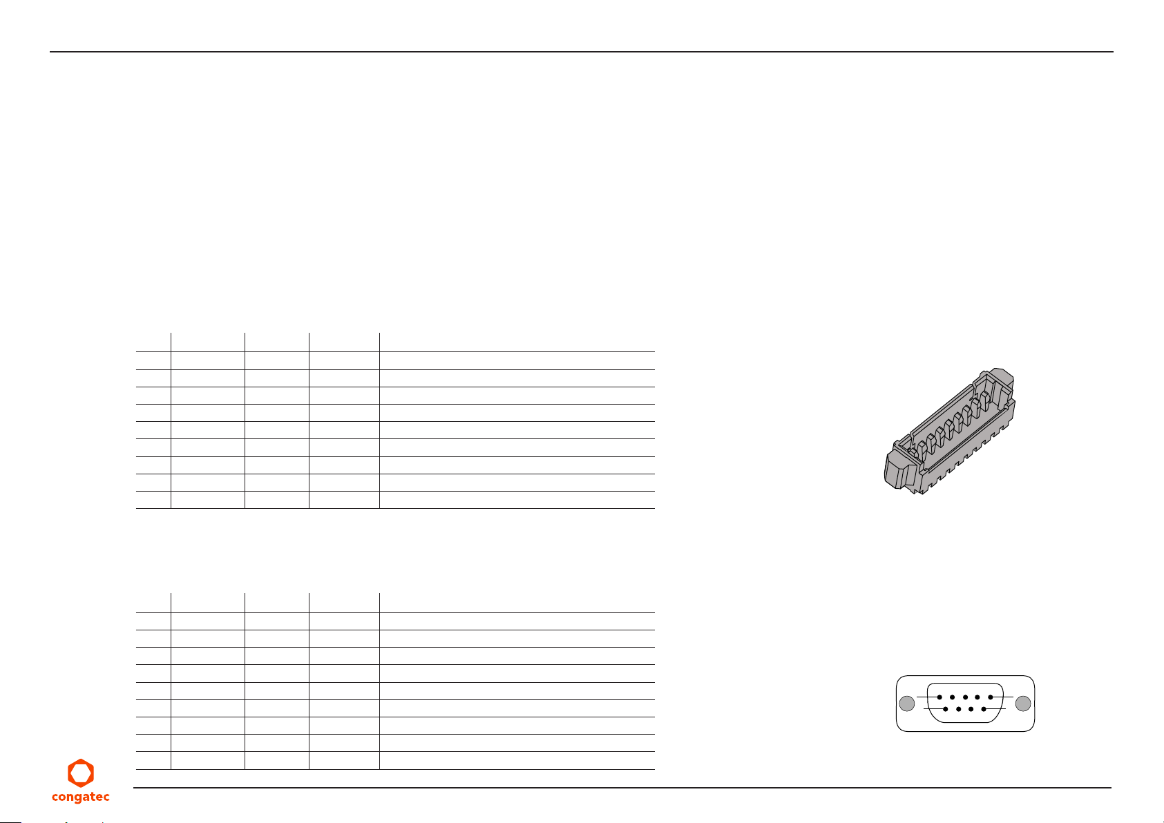
The conga-JC370 provides COM port 1 on D-SUB9 connector X10 and COM port 2 on pin header X11. The ports support RS232, RS422 and
RS485 I/O voltage levels. Select the COM port protocol in the BIOS setup menu.
Table 28 X11 Pinout Description
Pin RS232 RS422 RS485 Description
1 DCD Data Carrier Detect
2 DSR Data Set Ready
3 RXD RX- DATA- Receive Data/Receive Data +
4 RTS TX+ DATA+ Request to Send/Transmit Data +
5 TXD TX- DATA- Transmit Data/Transmit Data 6 CTS RX+ DATA + Clear to Send/Receive Data 7 DTR Data Terminal Ready
8 RI Ring Indicator
9 GND Ground
X11
Table 29 X10 Pinout Description
Pin RS232 RS422 RS485 Description
1 DCD Data Carrier Detect
2 RXD RX- DATA- Receive Data
3 TXD TX- DATA- Transmit Data
4 DTR Data Terminal Ready
5 GND Ground
6 DSR Data Set Ready
7 RTS TX+ DATA+ Request to Send/Transmit Data
8 CTS RX+ DATA + Clear to Send/Receive Data
9 RI Ring Indicator
Copyright © 2019 congatec AG JCWLm10 42/55
X10
1 5
96
Page 43
Note
1. The mating RS422/RS485 connector must have a termination resistor.
2. The mating RS485 connector must connect the DATA+ pins together and the DATA- pins together.
Connector Type
X10: Standard 9-pin DSUB male connector
X11: 9-pin, 1.25 mm pitch picoblade header (Molex 0533980971)
Possible Mating Connector: Molex 0510210900
5.8.2 COM Port 3 and 4 Headers
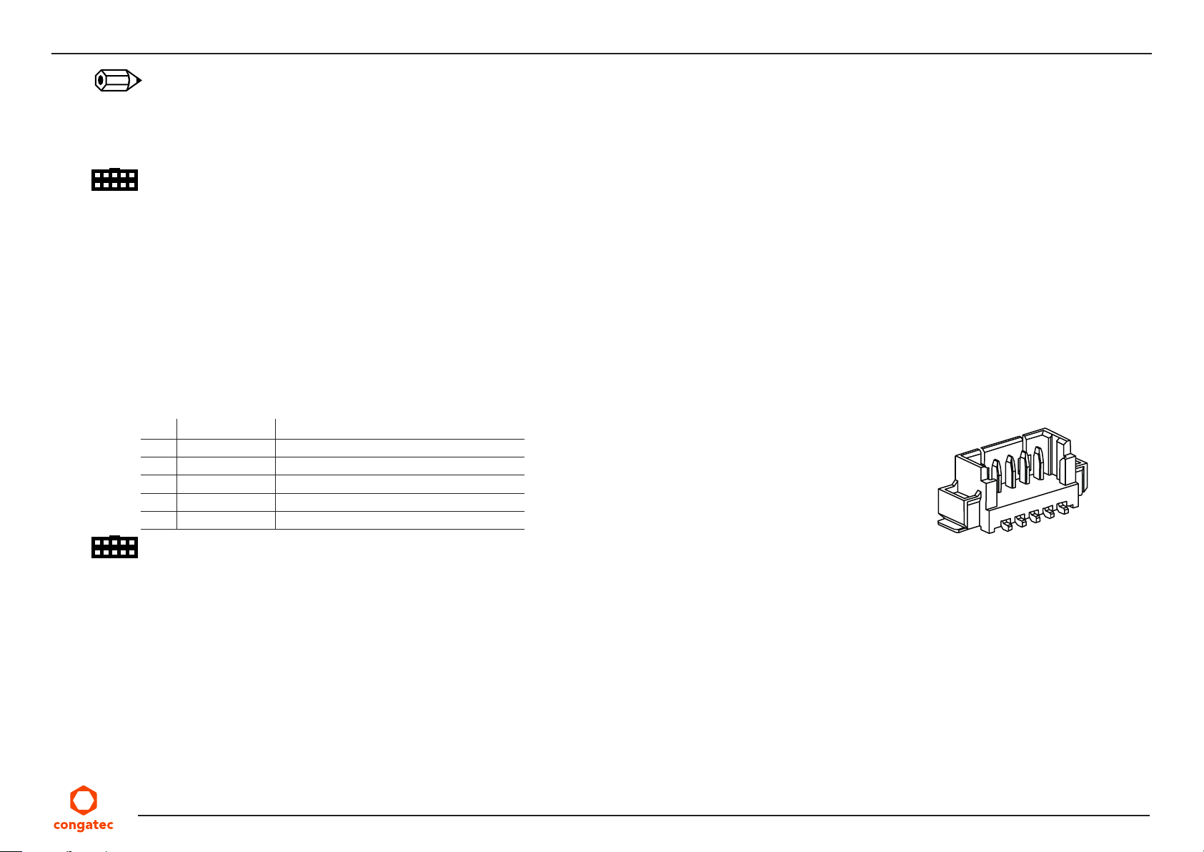
The conga-JC370 provides COM port 3 on X12 and COM port 4 on X13. The ports support RS 232 voltage level.
Table 30 X12/X13 Pinout Description
Pin Signal Description
1 GND Ground
2 TXD Transmit data
3 RTS Request to Send
4 CTS Clear to Send
5 RXD Receive data
Connector Type
X12/X13: 5-pin, 1.25 mm pitch picoblade header (Molex 0533980571)
Possible Mating Connector: Molex 0510210500
X12/X13
Copyright © 2019 congatec AG JCWLm10 43/55
Page 44
5.9 GPIO Header
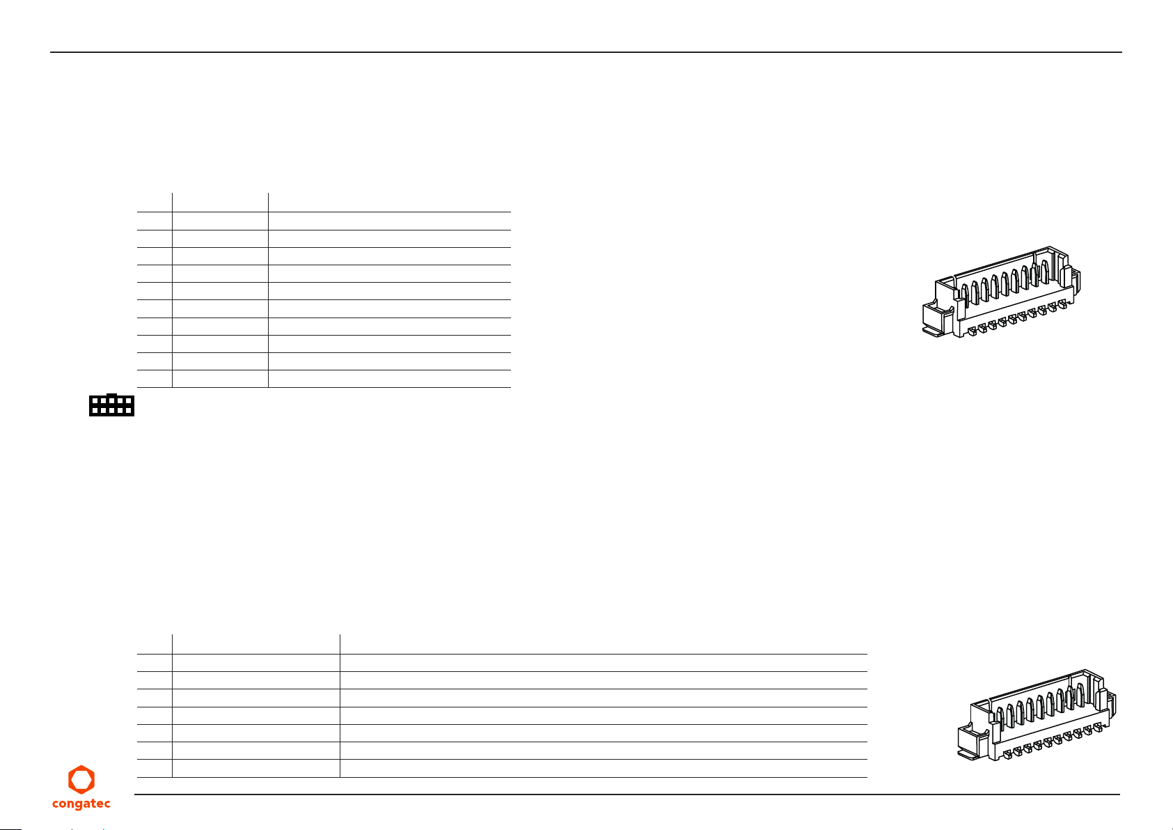
The conga-JC370 provides eight GPIOs on connector X5, via the congatec Board Controller. The 3.3 V is provided through a 500 mA resetable
fuse.
Table 31 X5 Pinout Description
Pin Signal Description
1 GPIO_0 General Purpose Input Output 0
2 GPIO_1 General Purpose Input Output 1
3 GPIO_2 General Purpose Input Output 2
4 GPIO_3 General Purpose Input Output 3
5 GND Ground
6 GPIO_4 General Purpose Input Output 4
7 GPIO_5 General Purpose Input Output 5
8 GPIO_6 General Purpose Input Output 6
9 GPIO_7 General Purpose Input Output 7
10 + 3.3 V 3.3 V supply (standby)
Connector Type
X5: 10-pin, 1.25 mm pitch picoblade header (Molex 0533981071)
Possible Mating Connector: Molex 0510211000
X5
5.10 System Management Header
The conga-JC370 provides header X6 for system management. The header can alternatively support eight GPIOs (GPIO_8 to GPIO_15) via
assembly option.
Table 32 X6 Pinout Description
Pin Signal Description
1 PWROK/GPIO_8 Power good/General Purpose Input Output 8
2 PM_BATLOW#/GPIO_9 Battery low signal/General Purpose Input Output 9
3 GBE2_SDP0/GPIO_10 Gigabit Ethernet Software-Definable Pin/General Purpose Input Output 10
4 WDG_TRIG#/GPIO_11 Watchdog trigger/General Purpose Input Output 11
5 GND Ground
6 PM_SLP_S3#/GPIO_12 Suspend to RAM state (active low output)/General Purpose Input Output 12
7 PM_SLP_S4#/GPIO_13 Suspend to Disk state (active low output)/General Purpose Input Output 13
Copyright © 2019 congatec AG JCWLm10 44/55
X6
Page 45
8 PM_SLP_S5#/GPIO_14 Soft-off state/General Purpose Input Output 14
9 WDG_EVENT/GPIO_15 Watchdog event/General Purpose Input Output 15
10 + 3.3 V 3.3 V supply (standby)
5.11 I²C Bus/SM Bus Header
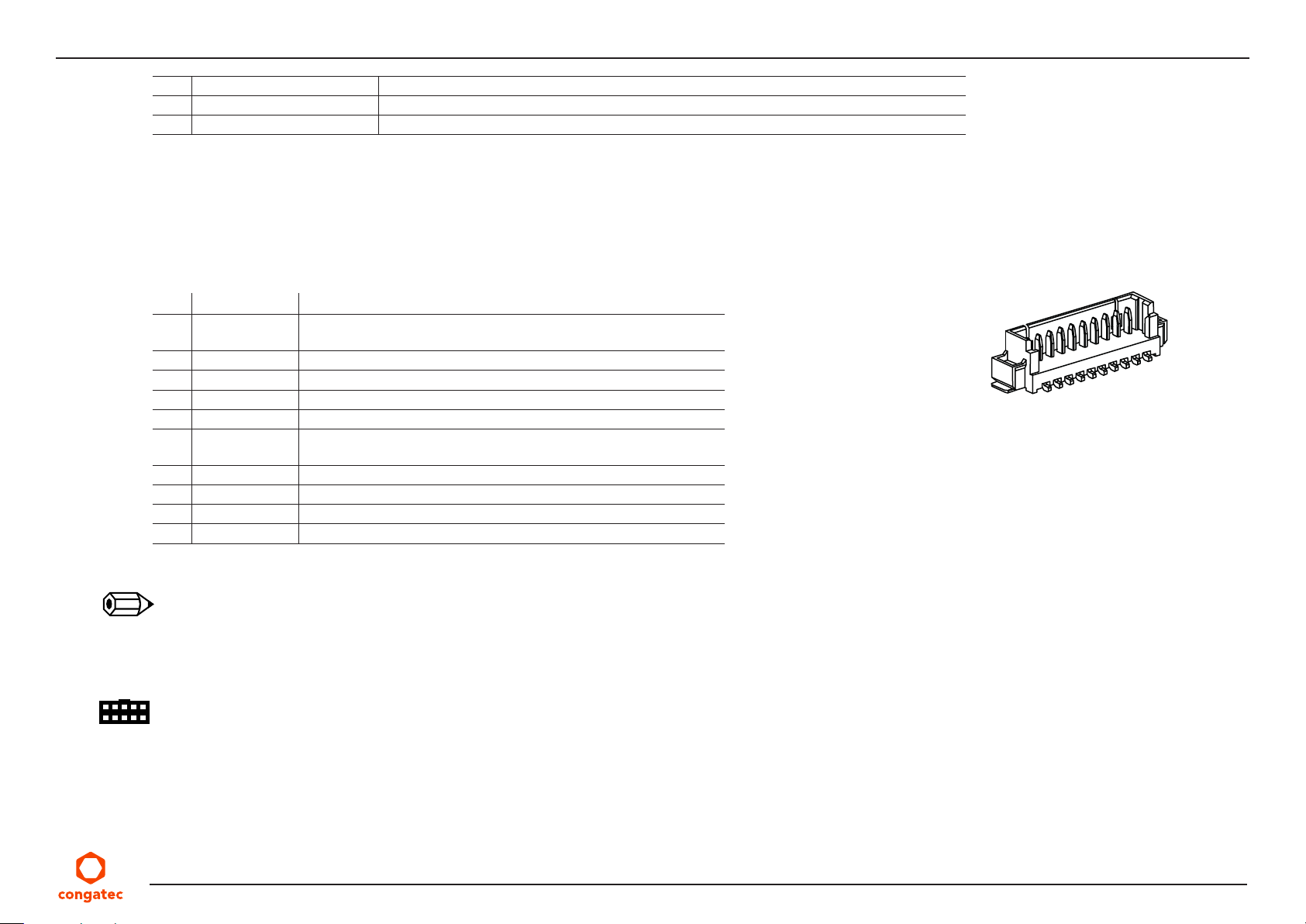
The conga-JC370 provides header X7 for I²C/SM bus signals. The 3.3 V is provided through a 500 mA resetable fuse.
Table 33 X7 Pinout Description
Pin Signal Description
1 PM_THRM# Thermal event from external sensor (should be driven by open
drain/collector output)
2 I2C_DAT I2C data
3 GND Ground reference
4 I2C_CLK I2C clock output
5 +3.3 V +3.3 V (standby) power output with 500 mA fuse
6 SMB0_ALERT# SMBus Alert signal from external device (should be driven by open
drain/collector output)
7 SMB0_DAT SMBus data
8 GND Ground reference
9 SMB0_CLK SMBus clock output
10 + 3.3 V +3.3 V power output with 500 mA (active in deep sleep)
X7
Note
1. All signals have 3.3 V level
2. Pin 5 is recommended for I2C devices while pin 10 is recommended for SMBus devices
Connector Type
X7: 10-pin, 1.25 mm pitch picoblade header (Molex 0533981071)
Possible Mating Connector: Molex 0510211000
Copyright © 2019 congatec AG JCWLm10 45/55
Page 46
5.12 Front Panel Header
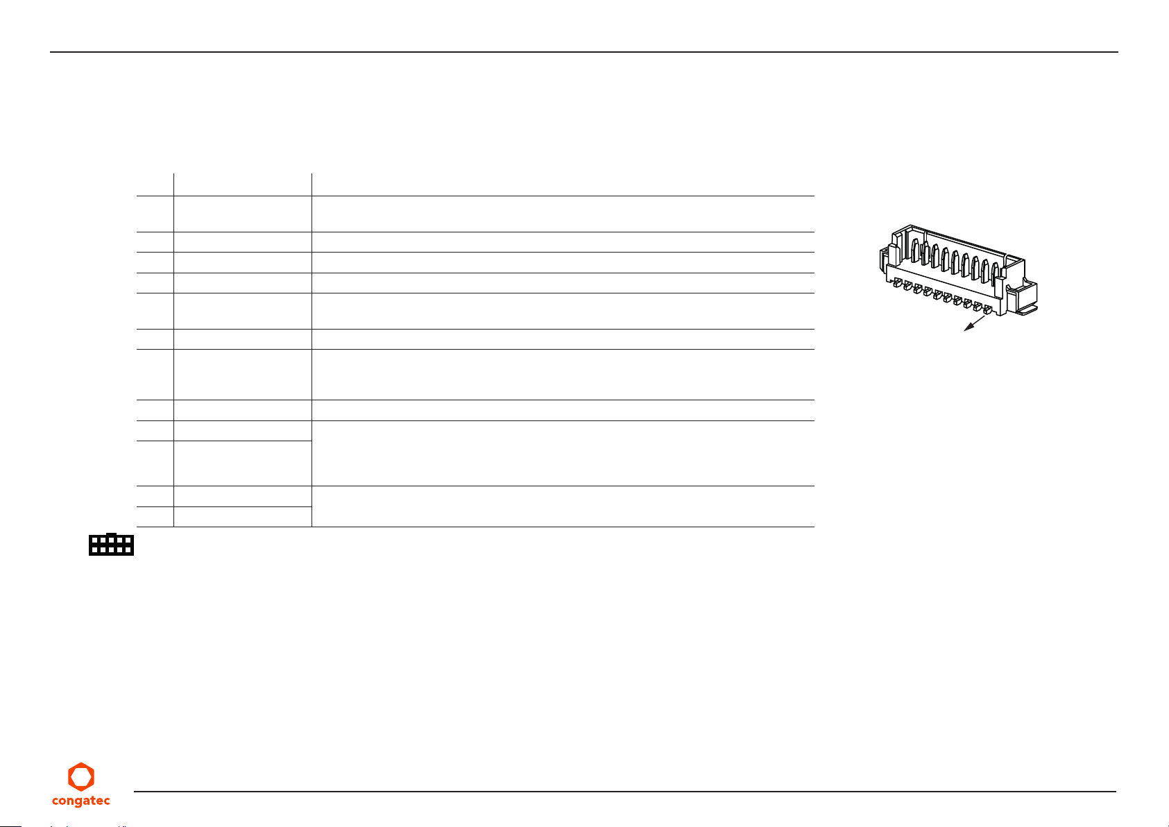
The conga-JC370 provides X4 for front panel features such as lid, sleep, reset and power buttons, as well as status LEDs.
Table 34 X4 Pinout Description
Pin Signal Name Description
1 LID_BTN# Active-low signal. Triggers sleep state, hibernation or shutdown (depends on OS
configuration)
2 GND Ground
3 SLP_BTN# Active-low signal. Triggers sleep state or hibernation (depends on OS configuration)
4 GND Ground
5 RST_BTN# Active-low signal. Triggers hard reset (system is not kept in reset when connected to
ground)
6 GND Ground
7 PWR_BTN# Active-low signal. Triggers power-up sequence. Pulse duration of ≥ 4 seconds triggers
forced shutdown. The cBC can also trigger signal depending on the BIOS settings (see
section 6.4.2 “Power Loss Control”)
8 GND Ground
9 PWR_LED (anode) For connecting bidirectional LEDs. The LEDs light when the system is powered on.
10 GND (cathode)
11 SATA_LED (anode) LED indicates activity on the SATA, mSATA (X26) or M.2 Type M socket (X28) with SATA
12 SATA_ACT# (cathode)
Main color (runtime state (S0)): pin 9 for anode and pin 10 for cathode
Alternate color (sleep state (S5)): pin 9 for cathode and pin 10 for anode
SSD (onboard series resistor makes it possible to connect the LEDs directly to the pins)
X4
pin 1
Connector Type
X4: 12-pin, 1.25 mm pitch (Molex 53398-1271)
Possible Mating Connector: Molex 0510211200
Copyright © 2019 congatec AG JCWLm10 46/55
Page 47
5.12.1 CPU Fan Header
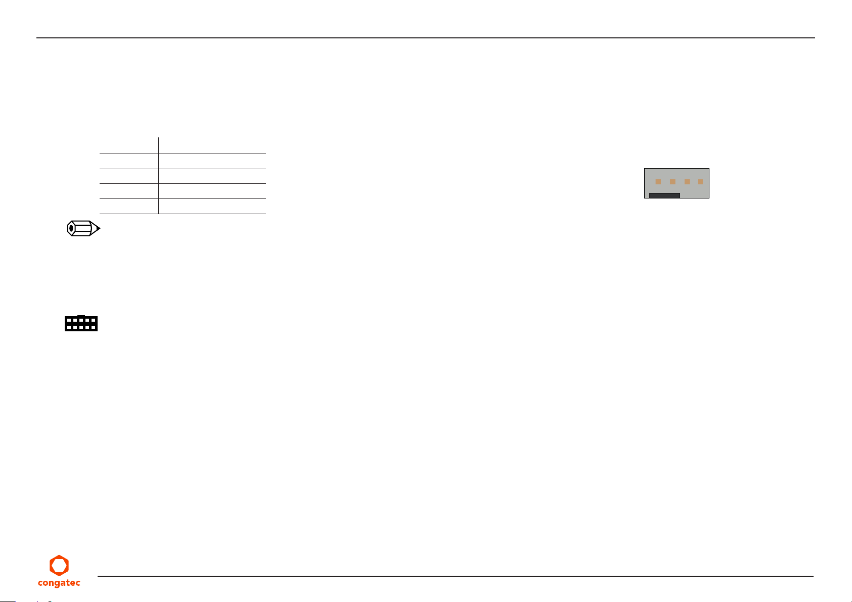
The conga-JC370 provides pin header X9 for connecting a 3-pin or 4-pin 12 V CPU fan. The recommended maximum power rating for the fan
is 4 W.
Table 35 X9 Pinout Description
Pin Signal
1 GND
2 +12 VDC
3 FAN_TACHOIN
4 FAN_CTRL
Note
1. The connector and pinout complies with 4-Wire Pulse PWM Controlled Fans Specification, Revision 1.3
2. FAN_TACHOIN fan output shall provide two pulses per revolution.
3. The fan must pull up the FAN_CTRL signal to high logic level
Connector Type
X9
1 2 3 4
X9: 2.54 mm, 4-pin grid female fan connector
Copyright © 2019 congatec AG JCWLm10 47/55
Page 48
6 Additional Features
6.1 Micro-SIM Card
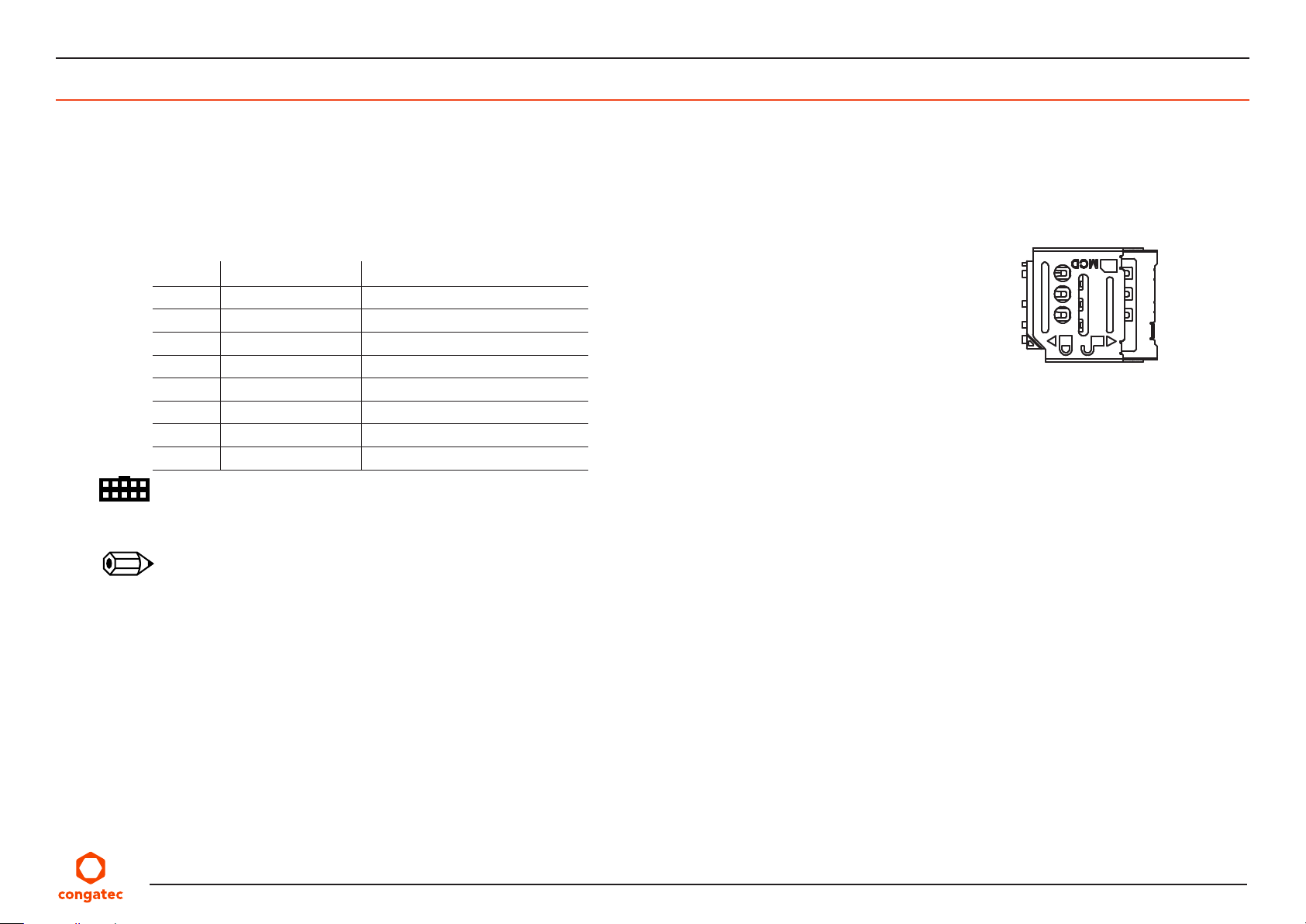
The conga-JC370 offers a micro-SIM slot on connector X25 for inserting SIM card.
Table 36 X25 Pinout Description
Pin Signal Description
C1 PWR Power
C2 RST Reset
C3 CLK Clock
C4 N.A Not available
C5 GND Ground
C6 N.C Not connected
C7 I/O Data
C8 N.A Not available
Connector Type
X25: Micro-SIM card socket (Molex 78800 series)
Note
1. The micro-SIM card slot is connected to the UIM interface of M.2 socket (X24) by default.
2. The slot can optionally be connected to the UIM interface of the mPCIe socket (X26).
X25
Copyright © 2019 congatec AG JCWLm10 48/55
Page 49
6.2 Case-open Intrusion Connector
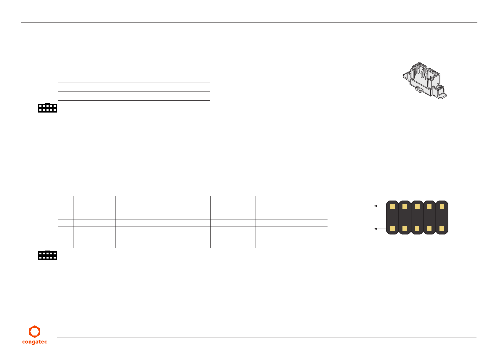
The conga-JC370 provides connector X3 for case-open intrusion detection.
Table 37 X3 Pinout Description
Pin Function
1 INTRUDER#
2 GND
Connector Type
X3: 1.25 mm, 2-pin Molex Picoblade
6.3 External BIOS Flash
With pin header X37, the conga-JC370 can boot from an external 3.3 V SPI flash. For external BIOS flash, you need an SPI flash with a PCB
adapter that connects to X37. For more information, contact congatec support.
Table 38 X37 Pinout Description
Pin Signal Description Pin Signal Description
1 SPI_CS0B# SPI flash CS# pin 2 VDD Power supply (3.3 V)
3 SPI_IO1 SPI flash MISO pin 4 SPI_IO3 SP flash HOLD# pin
5 SPI_IO2 SPI flash WP# pin 6 SPI_CLK SPI flash clock input
7 GND Ground 8 SPI_IO0 SPI flash MOSI pin
9 BIOS_EXT# Enable booting from external SPI flash
(active low)
X3
X37
Pin 2
Pin 1
10 SER1_TX Serial port debug output
Connector Type
X37: 1.27 mm, 2 x 5-pin header
Copyright © 2019 congatec AG JCWLm10 49/55
Page 50

6.4 congatec Board Controller (cBC)
The conga-JC370 is equipped with a Microchip MEC1705 microcontroller. This onboard microcontroller plays an important role for most of the
congatec BIOS features. It fully isolates some of the embedded features such as system monitoring, I²C bus from the x86 core architecture. The
isolation helps improve performance and reliability even when the x86 processor is in a low power mode.
6.4.1 Fan Control
The cBC uses the PWM (FAN_PWMOUT) signal to adjust the rotational speed of the fan without changing the fan’s input voltage. Additionally,
the FAN_TACHOIN signal provides the ability to monitor the system’s fan RPMs (revolutions per minute). For accurate RPM reading, the
FAN_TACHOIN signal must receive two pulses per revolution. Therefore, a two pulse per revolution fan or similar hardware solution is
recommended.
6.4.2 Power Loss Control
The cBC has full control of the power-up of the SBC; therefore, it can be used to specify the behavior of the system after an AC power loss
condition. Supported modes are “Always On”, “Remain Off” and “Last State”.
6.4.3 Board Information
The cBC provides a rich data-set of manufacturing and board information such as serial number, EAN number, hardware and firmware revisions.
It also keeps track of dynamically changing data like runtime meter and boot counter.
6.5 OEM BIOS Customization
The conga-JC370 is equipped with congatec Embedded BIOS, which is based on American Megatrends Inc. Aptio UEFI firmware. The congatec
Embedded BIOS allows system designers to modify the BIOS. For more information about customizing the congatec Embedded BIOS, refer to
the congatec System Utility user’s guide CGUTLm1x.pdf on the congatec website at www.congatec.com or contact technical support.
The customization features supported are described below:
6.5.1 OEM Default Settings
This feature allows system designers to create and store their own BIOS default configuration. Customized BIOS development by congatec for
OEM default settings is no longer necessary because customers can easily perform this configuration by themselves using the congatec system
Copyright © 2019 congatec AG JCWLm10 50/55
Page 51
utility CGUTIL. See congatec application note AN8_Create_OEM_Default_Map.pdf on the congatec website for details on how to add OEM
default settings to the congatec Embedded BIOS.
6.5.2 OEM Boot Logo
This feature allows system designers to replace the standard text output displayed during POST with their own BIOS boot logo. Customized
BIOS development by congatec for OEM Boot Logo is no longer necessary because customers can easily perform this configuration by
themselves using the congatec system utility CGUTIL. See congatec application note AN11_Create_And_Add_Bootlogo.pdf on the congatec
website for details on how to add OEM boot logo to the congatec Embedded BIOS.
6.5.3 OEM POST Logo
This feature allows system designers to replace the congatec POST logo displayed in the upper left corner of the screen during BIOS POST
with their own BIOS POST logo. Use the congatec system utility CGUTIL 1.5.4 or later to replace or add the OEM POST logo.
6.5.4 OEM BIOS Code/Data
With the congatec embedded BIOS, system designers can add their code to the BIOS POST process. The congatec Embedded BIOS first calls
the OEM code before handing over control to the OS loader. Except for custom specific code, this feature can also be used to support verb
tables for HDA codecs, PCI/PCIe OpROMs, bootloaders, rare graphic modes and Super I/O controller initialization.
Note
The OEM BIOS code of the new UEFI based firmware is called only when the CSM (Compatibility Support Module) is enabled in the BIOS
setup menu. Contact congatec technical support for more information on how to add OEM code.
6.5.5 OEM DXE Driver
This feature allows designers to add their own UEFI DXE driver to the congatec embedded BIOS. Contact congatec technical support for more
information on how to add an OEM DXE driver.
Copyright © 2019 congatec AG JCWLm10 51/55
Page 52

6.6 congatec Battery Management Interface
To facilitate the development of battery powered mobile systems based on embedded modules, congatec AG defined an interface for the
exchange of data between a CPU module (using an ACPI operating system) and a Smart Battery system. A system developed according to
the congatec Battery Management Interface Specification can provide the battery management functions supported by an ACPI-capable
operating system (for example, charge state of the battery, information about the battery, alarms or events for certain battery states) without
the need for additional modifications to the system BIOS.
In addtion to the ACPI-Compliant Control Method Battery mentioned above, the latest versions of the conga-JC370 BIOS and board controller
firmware also support LTC1760 battery manager from Linear Technology and a battery only solution (no charger). All three battery solutions are
supported on the I2C bus and the SMBus. This gives the system designer more flexibility when choosing the appropriate battery sub-system.
For more information about this subject visit the congatec website and view the following documents:
• congatec Battery Management Interface Specification
• Battery System Design Guide
• conga-SBM3 User’s Guide
6.7 API Support (CGOS)
In order to benefit from the above mentioned non-industry standard feature set, congatec provides an API that allows application software
developers to easily integrate all these features into their code. The CGOS API (congatec Operating System Application Programming Interface)
is the congatec proprietary API that is available for all commonly used Operating Systems such as Win32, Win64, Win CE, Linux.
The architecture of the CGOS API driver provides the ability to write application software that runs unmodified on all congatec CPU modules.
All the hardware related code is contained within the congatec embedded BIOS on the module. See section 1.1 of the CGOS API software
developers guide, available on the congatec website.
6.8 Thermal and Voltage Monitoring
The cBC monitors the ambient temperature, input voltage and input current of the conga-JC370. The sensors in the CPU monitor the CPU
temperature.
Copyright © 2019 congatec AG JCWLm10 52/55
Page 53
6.9 Security Features
The conga-JC370 features a firmware TPM (Intel PTT TPM 2.0) as well as a discrete Infineon SLB9670 TPM 2.0.
Note
To use the discrete TPM module, disable the firmware TPM (fTPM) in the Advanced ->Platform Trust Technology -> fTPM BIOS setup submenu.
6.10 External System Wake Event
The conga-JC370 supports LAN, USB, power,lid, sleep buttons and PCIe driven wake-up events.
Copyright © 2019 congatec AG JCWLm10 53/55
Page 54
7 BIOS Setup Description
The BIOS setup description of the conga-JC370 can be viewed without having access to the module. However, access to the restricted area of
the congatec website is required in order to download the necessary tool (CgMlfViewer) and Menu Layout File (MLF).
The MLF contains the BIOS setup description of a particular BIOS revision. The MLF can be viewed with the CgMlfViewer tool. This tool offers
a search function to quickly check for supported BIOS features. It also shows where each feature can be found in the BIOS setup menu.
For more information, read the application note “AN42 - BIOS Setup Description” available at www.congatec.com.
Note
If you do not have access to the restricted area of the congatec website, contact your local congatec sales representative.
7.1 Navigating the BIOS Setup Menu
The BIOS setup menu shows the features and options supported in the congatec BIOS. To access and navigate the BIOS setup menu, press the
<DEL> or <F2> key during POST. The right frame displays the key legend. Above the key legend is an area reserved for text messages. These
text messages explain the options and the possible impacts when changing the selected option in the left frame.
7.2 BIOS Versions
The BIOS displays the BIOS project name and the revision code during POST, and on the main setup screen. The initial production BIOS for
conga-JC370 is identified as JVWLR1xx or JUWLR1xx, where:
• R is the identifier for a BIOS ROM file,
• 1 is the so called feature number and
• xx is the major and minor revision number.
The binary size for JVWL and JUWL is 32 MB.
Copyright © 2019 congatec AG JCWLm10 54/55
Page 55
7.3 Updating the BIOS
BIOS updates are recommeded to correct platform issues or enhance the feature set of the module. The conga-JC370 features a congatec/AMI
AptioEFI firmware on an onboard flash ROM chip. You can update the firmware with the congatec System Utility. The utility has five versions—
UEFI shell, DOS based command line
For more information about “Updating the BIOS” refer to the user’s guide for the congatec System Utility “CGUTLm1x.pdf” on the congatec
website at www.congatec.com.
Note
1.
Deprecated
Caution
The DOS command line tool is not officially supported by congatec and therefore not recommended for critical tasks such as firmware
updates. We recommend to use only the UEFI shell for critical updates.
7.4 Supported Flash Devices
The conga-JC370 supports:
1
, Win32 command line, Win32 GUI, and Linux version.
• Winbond W25Q256JVEIQ (32 MB)
• GigaDevice GD25B256DYIG (32 MB)
The flash devices above can be used to support external BIOS. For more information about external BIOS support, refer to the Application
Note “AN7_External_BIOS_Update.pdf” on the congatec website at http://www.congatec.com.
Copyright © 2019 congatec AG JCWLm10 55/55
 Loading...