

Concordia Coffee 99702 Service Manual

A
scent Brewer
Technician’s Manual


Concordia Beverage Systems
1287 120th Avenue NE
Bellevue, WA 98005
USA
(425) 453-2800
(800) 778-0990
(425) 453-2167 Fax
http://www.concordiacoffee.com/
Technical Writer: Shana McKibbin
Technical Support: Gery Jaggars, Chris Collier, Brad Butler
Graphic Engineer: Seth Cope
Software: Allen Moore
Edition: October, 2014
2900-331x2
Revision Change Log
Replace
Old
Section
4 4
With New
Section
Brief Description Date
Updates to content in
Software section
November,
2014
XXX
Revision
B

TableofContents
Section 1 :: Ascent Brewer Overview..............................................................................1-1
Ascent Brewer External Machine Overview........................................................1-2
Ascent Brewer External Machine Components.............................1-3
Ascent Brewer Internal Machine Overview – Front View....................................1-4
Ascent Brewer Internal Machine Components – Front.................1-5
Internal Machine Overview – Rear View.............................................................1-6
Internal Machine Components – Rear ..........................................1-7
Removing a Side Panel ......................................................................................1-8
Removing the Back Panel...................................................................................1-9
Removing the Top Panel ..................................................................................1-10
Removing the Front Panel................................................................................1-11
Section 2 :: Installation....................................................................................................2-1
Technical Specifications and Site Requirements................................................2-2
Dimensions....................................................................................2-3
Installation...........................................................................................................2-4
Plumbing........................................................................................2-4
Water Supply.................................................................................2-4
Problems with Reverse Osmosis Water System...........................2-4
Additional Tasks Required at Installation............................................................2-5
Power Up the Machine..................................................................2-5
Install Bean Hoppers.....................................................................2-5
Section 3 :: Electrical.......................................................................................................3-1
Electrical System Overview ................................................................................3-2
AC Block Diagram...............................................................................................3-3
I/O Harness Board Diagram................................................................................3-4
DC Power Supply Diagram.................................................................................3-5
Section 4 :: Software.......................................................................................................4-1
Software Overview..............................................................................................4-2
Software Menu Categories............................................................4-2
Accessing the Software Menu.......................................................4-2
Accessing Different User Access Levels.......................................4-2
Resetting the User Access Level ..................................................4-2
Scrolling in the Menu.....................................................................4-3
Accessing a Sub-Category............................................................4-3
Changing a Value..........................................................................4-3
Exiting a Sub-Category .................................................................4-3
Exiting the Main Menu...................................................................4-3
Check Beverage Statistics ............................................................4-3
User Interface Test..............................................................................................4-4
Menu Shortcuts...................................................................................................4-4
Software Quick Reference Table........................................................................4-5
Updating Software...............................................................................................4-7
Installing or Updating Software.....................................................4-7
Calibration...........................................................................................................4-8
Coffee Extraction and Temperature Parameters ..........................4-8
Beverage Temperatures................................................................4-8
Section 5 :: Plumbing......................................................................................................5-1
The Water System ..............................................................................................5-2
Hydraulics Diagram.......................................................................5-2
Water Supply.......................................................................................................5-3
Line Pressure ................................................................................5-3
Water Inlet.....................................................................................5-3

Water Pump...................................................................................5-3
Removing the Water Pump Assembly ..........................................5-4
Flowmeter......................................................................................5-5
Removing the Flowmeter ..............................................................5-6
Pressure Regulator .......................................................................5-7
Removing the Pressure Regulator................................................5-7
Hot Water Tank Assembly ..................................................................................5-8
Level Probe ...................................................................................5-8
Heating Element............................................................................5-8
Hi Temperature Limit Switch.........................................................5-8
Pressure Relief Valve....................................................................5-8
Expansion Valve............................................................................5-9
Temperature Probe.......................................................................5-9
Removing the Hot Water Tank....................................................5-10
Water Valves.....................................................................................................5-12
Brew and Hot Water Valve Assembly.........................................5-12
Removing/Replacing a Valve......................................................5-13
Section 6 :: Coffee System .............................................................................................6-1
Coffee System Overview ....................................................................................6-2
Grinder Overview................................................................................................6-3
Upper and Lower Grinder Burrs....................................................6-4
Replacing Bean Grinder Burrs/Blades..........................................6-4
Grounds Chute..............................................................................6-4
Removing a Bean Grinder.............................................................6-5
Brew Group.........................................................................................................6-6
Brew Group Components..............................................................6-7
Removing the Brew Group............................................................6-8
Bean Hoppers...................................................................................................6-10
Filling a Bean Hopper..................................................................6-10
Removing a Bean Hopper...........................................................6-10
Inserting a Hopper Stopper.........................................................6-10
Replacing a Bean Hopper...........................................................6-10
Dispense Valve Assembly...........................................................6-11
Drain Valve Assembly.................................................................6-11
Section 7 :: Cleaning and Maintenance..........................................................................7-1
Machine Maintenance.........................................................................................7-2
Concordia Cleaning Products........................................................7-2
Cleaning Timer....................................................................................................7-2
Daily Cleaning Procedures .................................................................................7-3
Perform the Brew Clean Cycle......................................................7-3
Empty the Grounds Bin.................................................................7-4
Clean the Drain Grate and the Drain Tray ....................................7-4
Clean Exterior Surfaces ................................................................7-4
Clean the Product Nozzle..............................................................7-4
Refill Consumables .......................................................................7-4
Monthly Cleaning Procedure...............................................................................7-4
Clean the Bean Hoppers...............................................................7-4
Preventive Maintenance .....................................................................................7-5
PM Kits..........................................................................................7-5
Section 8 :: Messages.....................................................................................................8-1
Troubleshooting Display Messages....................................................................8-2
Section 9 :: Troubleshooting...........................................................................................9-1
Troubleshooting Quick Reference Guide............................................................9-2
Machine Failure.............................................................................9-2
Coffee System...............................................................................9-2
Section 10 :: Parts Lists & Diagrams ............................................................................10-1

Recommended Tools List.................................................................................10-2
Standard Tools............................................................................10-2
Parts Lists and Diagrams............................................................10-3
Diagram 1: Machine Overview....................................................10-4
Diagram 1, Parts List: Machine Overview...................................10-5
Diagram 2: Single Grinder Assembly..........................................10-6
Diagram 2, Parts List: Single Grinder Assembly.........................10-7
Diagram 3: Double Grinder Assembly.........................................10-8
Diagram 3, Parts List: Double Grinder Assembly........................10-9
Diagram 4: Group Upper and Lower Piston Assembly.............10-10
Diagram 4, Parts List: Group Upper and Lower Piston Assembly10-
11
Diagram 5: Water Pump Assembly...........................................10-12
Diagram 5, Parts List: Water Pump Assembly..........................10-13
Diagram 6: Hot Water Tank Assembly......................................10-14
Diagram 6, Parts List: Hot Water Tank Assembly.....................10-15
Diagram 7: Product Nozzle Assembly.......................................10-16
Diagram 7, Parts List: Product Nozzle Assembly......................10-17
Diagram 8: Front Panel Assembly ............................................10-18
Diagram 8, Parts List: Front Panel Assembly ...........................10-19
Diagram 9: Electrical Enclosure................................................10-20
Diagram 9, Parts List: Electrical Enclosure...............................10-21
Diagram 10: Upper Piston Assembly........................................10-22
Diagram 10, Parts List: Upper Piston Assembly.......................10-23
Diagram 11: Grinder Chute Assembly ......................................10-24
Diagram 11, Parts List: Grinder Chute Assembly.....................10-25
Diagram 12: Grounds Bin..........................................................10-26
Diagram 12, Parts List: Grounds Bin.........................................10-27
Section 11 :: Index ........................................................................................................11-1
Section 12 :: Service Bulletins ......................................................................................12-1
Service Bulletins................................................................................................12-2

Page Intentionally Left Blank

Section 1 :: Ascent Brewer
Overview
1. External Machine Overview
2. Internal Machine Overview – Front View
3. Internal Machine Overview – Rear View
4. Side Panel Removal Instructions
5. Back Panel Removal Instructions
6. Top Panel Removal Instructions
7. Front Panel Removal Instructions
TECHNICAL SUPPORT
Section 1: Ascent Brewer Overview 3035-001A
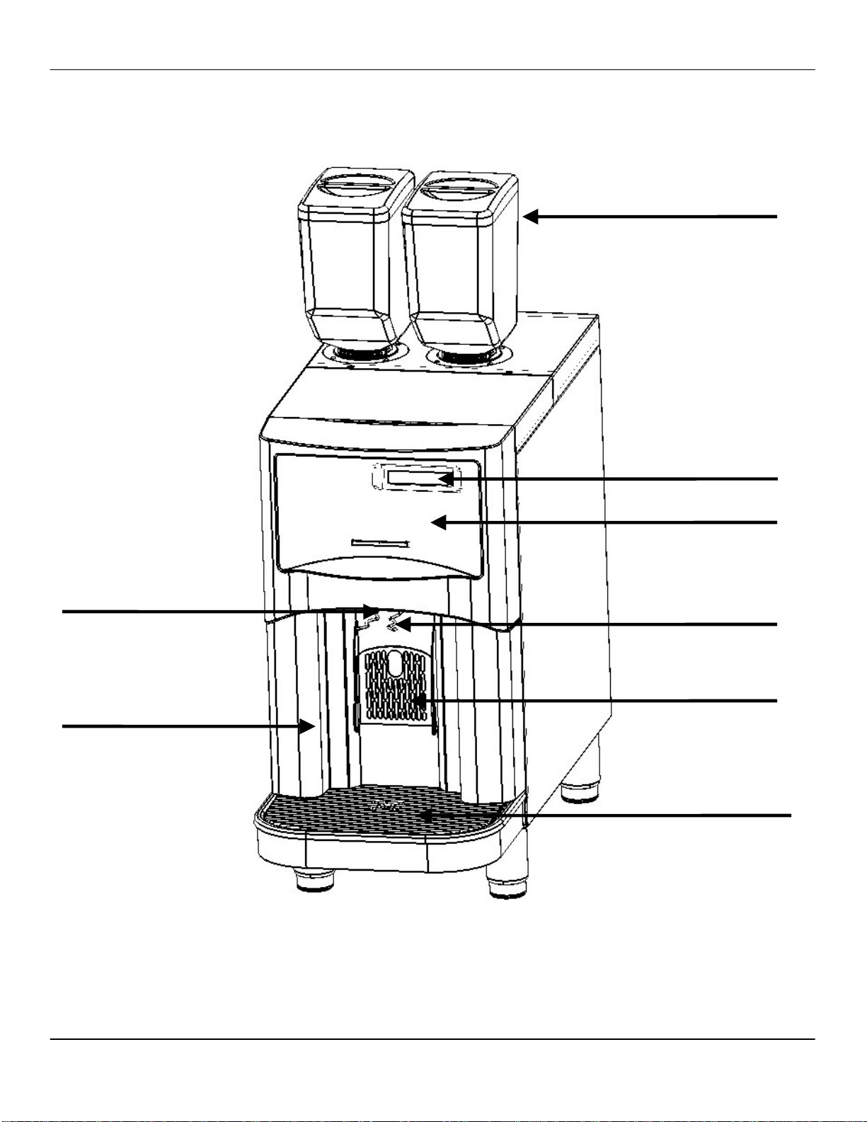
Ascent Brewer External Machine Overview
Bean Hoppers
Display
Product Nozzle
Grounds Bin
Front Panel
Carafe Hooks
Cup Shelf
Drain Grate and Drain Tray
1-2 Concordia Ascent Technical Support Manual
2900-331

3035-001A Section 1: Ascent Brewer Overview
Ascent Brewer External Machine Components
Power Switch
NOT SHOWN
The power switch is located on the back, upper left side of the machine.
Bean Hoppers
Each bean hopper holds approximately two pounds of beans.
Touch Pad
A touch pad provides a user-friendly interface for selecting and pouring
beverages. It also provides access to brew system statistics and service
functions.
Product Nozzle
Finished beverages are poured through the product nozzle and into the
cup or bulk-fill container.
Front Panel
The front panel provides access to the interior of the machine, for
cleaning, maintenance, and service.
Grounds Bin
A grounds bin is attached to the back of the bottom of the lower front of
the machine. The grounds bin holds used coffee grounds.
Carafe Hook
The carafe hook provides stability for a coffee carafe, while it is being
filled.
Cup Shelf
For use when pouring an individual beverage. The cup shelf folds up for
when a carafe or To Go Container is being filled.
Drain Grate and Drain Tray
The metal drain grate and the hard-plastic drain tray direct excess amd
waste liquid into the drain.
Concordia Ascent Technical Support Manual 1-3
2900-331
Section 1: Ascent Brewer Overview 3035-001A
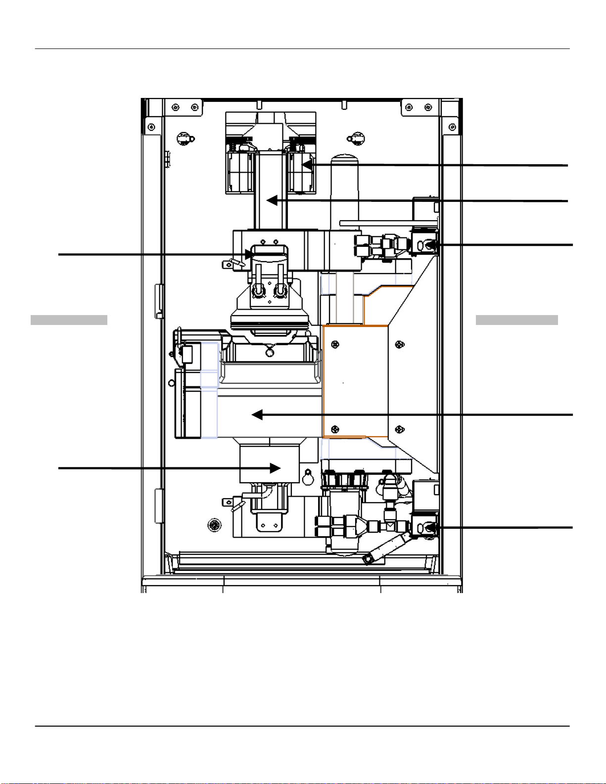
Ascent Brewer Internal Machine Overview – Front View
Grinders
Grounds Chute
Upper Piston
LEFT OF MACHINE RIGHT OF MACHINE
Lower Piston
Dispense Valve
Brew Group
Brew + Hot Water Valves
1-4 Concordia Ascent Technical Support Manual
2900-331

3035-001A Section 1: Ascent Brewer Overview
Ascent Brewer Internal Machine Components – Front
Grinders
Each bean grinder is calibrated to grind beans according to preprogrammed recipes for each type of bean.
Grounds Chute
A grounds chute is located between the grinder and the brew group.
Once the grinder has ground the coffee beans, the coffee grounds are
directed down the grounds chute into the brew chamber where water is
introduced to brew the coffee.
The coffee powder is pressed between the pistons and water is
introduced to brew coffee.
Dispense Valve
The dispense valve controls the flow of coffee to the product nozzle.
Brew Group
The brew group assembly collects ground coffee from the grinders,
brews and dispenses coffee, then discards the used coffee grounds into
the grounds bin.
Brew and Hot Water Valves
The brew valve controls the water flow to the brew group.
The hot water valve is used for dispensing hot water into the cup.
Lower Piston
Hot water passes through the lower piston, into the brew chamber, and
then through the ground coffee during a beverage pour.
Upper Piston
Once the coffee is brewed in the brew chamber, the brewed coffee
passes through the upper piston microscreen, through the dispense
valve, and then to the product nozzle. When coffee is ground and
delivered into the brew chamber, the left piston moves up to pack the
coffee against the upper piston.
Concordia Ascent Technical Support Manual 1-5
2900-331
Section 1: Ascent Brewer Overview 3035-001A
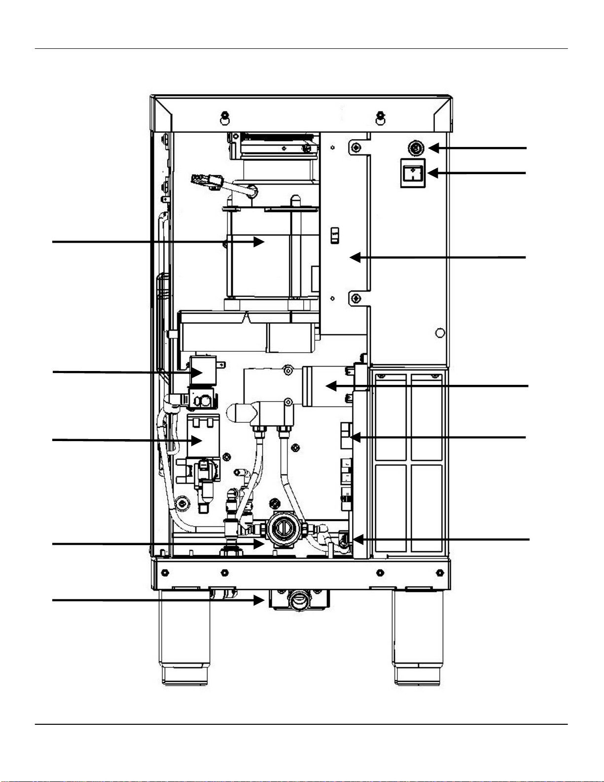
Internal Machine Overview – Rear View
Main Power
Circuit Breaker
Power Switch
Grinders
DC Power
Cold Water Valve
Drain Valve
Pressure Regulator
Drain
Water Pump
AC Control
System
Flowmeter
1-6 Concordia Ascent Technical Support Manual
2900-331

3035-001A Section 1: Ascent Brewer Overview
Internal Machine Components – Rear
Hot Water Tank
NOT SHOWN
The hot water tank stores and heats water used to brew the coffee.
Main Power Circuit Breaker
The main power circuit breaker protects the machine if there is an
electrical malfunction (i.e. overload) or a short circuit.
Power Switch
The power switch controls power to the machine.
DC Power
The DC power area houses all the components that provide DC voltage
for the machine.
Water Pump
The water pump pumps water at 25gph during the extraction process.
AC Control System
The AC control system houses all the components that provide AC
voltage for the machine.
Flowmeter
The flowmeter measures the water flowing throughout the system.
Drain
The drain transports excess and waste water away from the machine,
and ensures its appropriate disposal.
Pressure Regulator
The pressure regulator regulates the water pressure to the brew
chamber during the drink cycle.
Drain Valve
The drain valve controls the flow of waste water to the drain.
Cold Water Valve
OPTIONAL
The cold water valve provides water used for iced coffee beverages.
Concordia Ascent Technical Support Manual 1-7
2900-331
Section 1: Ascent Brewer Overview 3035-001A
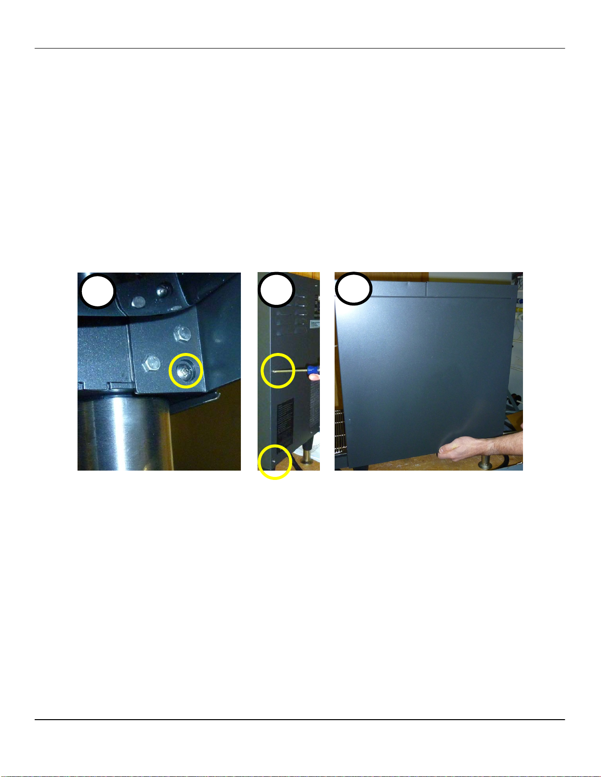
Removing a Side Panel
NOTE: This procedure describes how to remove the right side panel.
This procedure can be applied to both the right and left side panels.
NOTE: The right and left side panels are not interchangeable, so if
you’ve removed both panels and are having a difficult time reinstalling a
panel, try installing it on the other side of the machine.
1. Loosen one screw on the bottom of the machine, next to the right
front machine leg. See photo below.
2. Remove the middle screw on the back panel. See photo below.
3. Hold the bottom of the side panel as you remove the final screw,
as it will start to slide down as soon as the final screw is
removed. See photo below.
To reinstall this component, reverse the removal instructions.
1
2
1-8 Concordia Ascent Technical Support Manual
2900-331
3035-001A Section 1: Ascent Brewer Overview
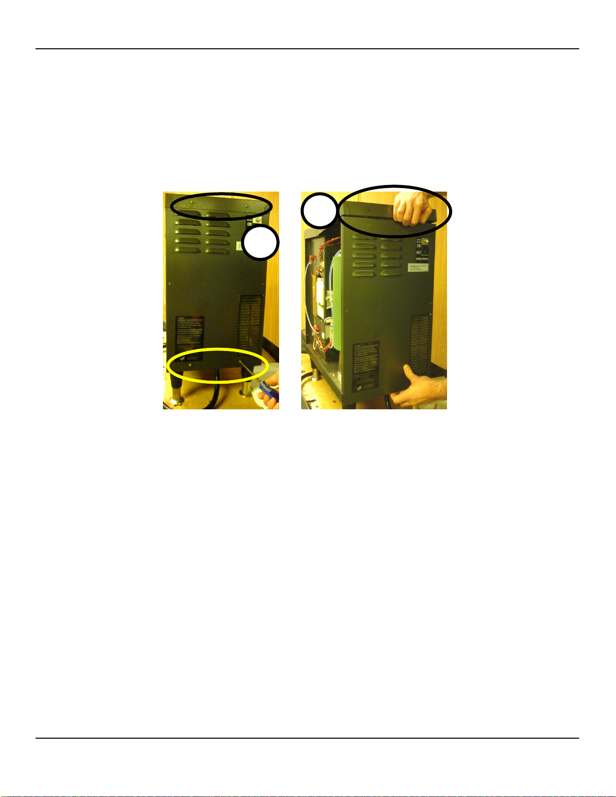
Removing the Back Panel
1. Remove the right and left side panels. See page 1-8.
2. Remove four screws on the back panel. See photo below.
3. To remove the rear panel, lift the edge of the top panel, and then
tilt the top of the back panel towards you. See photo below.
4. Remove the back panel.
To reinstall this component, reverse the removal instructions.
3
2
Concordia Ascent Technical Support Manual 1-9
2900-331
Section 1: Ascent Brewer Overview 3035-001A
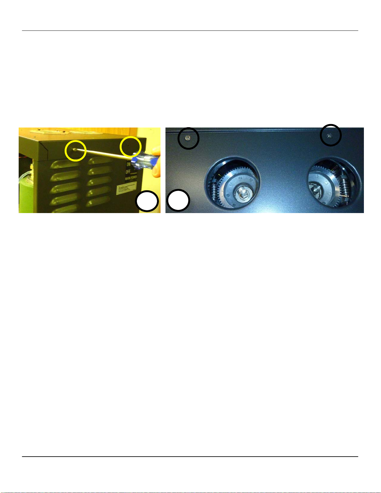
Removing the Top Panel
1. Remove the bean hoppers.
2. Remove two screws on the top of the back panel. Use a #2
Philips screwdriver. See photo below.
3. Raise the front panel assembly.
4. Remove the screws on top of the machine. See photo below.
5. Lift and remove the top panel.
To reinstall this component, reverse the removal instructions.
2
4
1-10 Concordia Ascent Technical Support Manual
2900-331
3035-001A Section 1: Ascent Brewer Overview
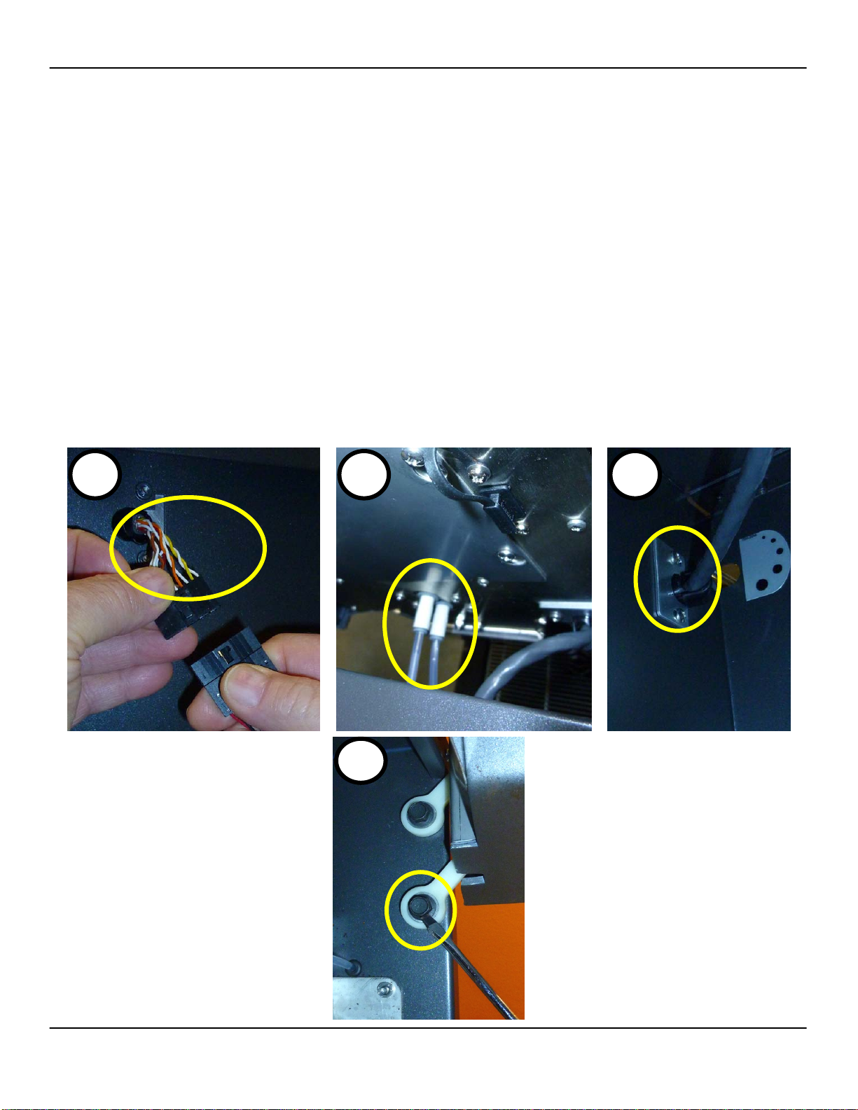
Removing the Front Panel Removing the Front Panel
1. Turn the power to the machine off. 1. Turn the power to the machine off.
2. Remove the left side panel. See page 1-8. 2. Remove the left side panel. See page 1-8.
3. Disconnect the front panel interface cable. See photo below. 3. Disconnect the front panel interface cable. See photo below.
4. Disconnect the two tubes connected to the back of the front
4. Disconnect the two tubes connected to the back of the front
panel. Press the collar down on each tube, to release. See
panel. Press the collar down on each tube, to release. See
photo below.
photo below.
5. Remove the two screws holding the front panel interface cable,
5. Remove the two screws holding the front panel interface cable,
on the inside of the machine. See photo below.
on the inside of the machine. See photo below.
6. Pull the power wires through the opening on the side panel. 6. Pull the power wires through the opening on the side panel.
NOTE: Avoid forcibly pulling the wires, to avoid damage. NOTE: Avoid forcibly pulling the wires, to avoid damage.
7. Remove four bolts (two on each side). See photo below. 7. Remove four bolts (two on each side). See photo below.
8. Remove the front panel. 8. Remove the front panel.
To reinstall this component, reverse the removal instructions. To reinstall this component, reverse the removal instructions.
NOTE: When reinstalling the panel, tighten the lower bolts (one on each
NOTE: When reinstalling the panel, tighten the lower bolts (one on each
side) to ensure that there is enough resistance. The front panel should
side) to ensure that there is enough resistance. The front panel should
not be hard to press down, nor should it slide down if not held open, and
not be hard to press down, nor should it slide down if not held open, and
the front panel should be level on both sides when it is raised.
the front panel should be level on both sides when it is raised.
3 5
4
Concordia Ascent Technical Support Manual 1-11
2900-331

Section 1: Ascent Brewer Overview 3035-001A
Page Intentionally Left Blank
1-12 Concordia Ascent Technical Support Manual
2900-331

Section 2 :: Installation
1. Technical Specifications and Site
Requirements
2. Installation
3. Additional Tasks Required at Installation
TECHNICAL SUPPORT
Section 2: Installation 3035-002A
Technical Specifications and Site Requirements
To ensure the site is ready, the customer is required to complete and
return a pre-installation checklist. The customer is required to have
electrical, water, and a drain located within a specified distance from the
machine.
Technical Specifications
Weight: 125lbs/57kg
Operating Environment: 40-90°F/13-29°C
Compliance:
FCC: Pending
UL Listed Pending
NSF Certified Pending
CE Compliant Pending
CSA Compliant Pending
RoHS Compliant Pending
Location Requirements
Locate indoors only
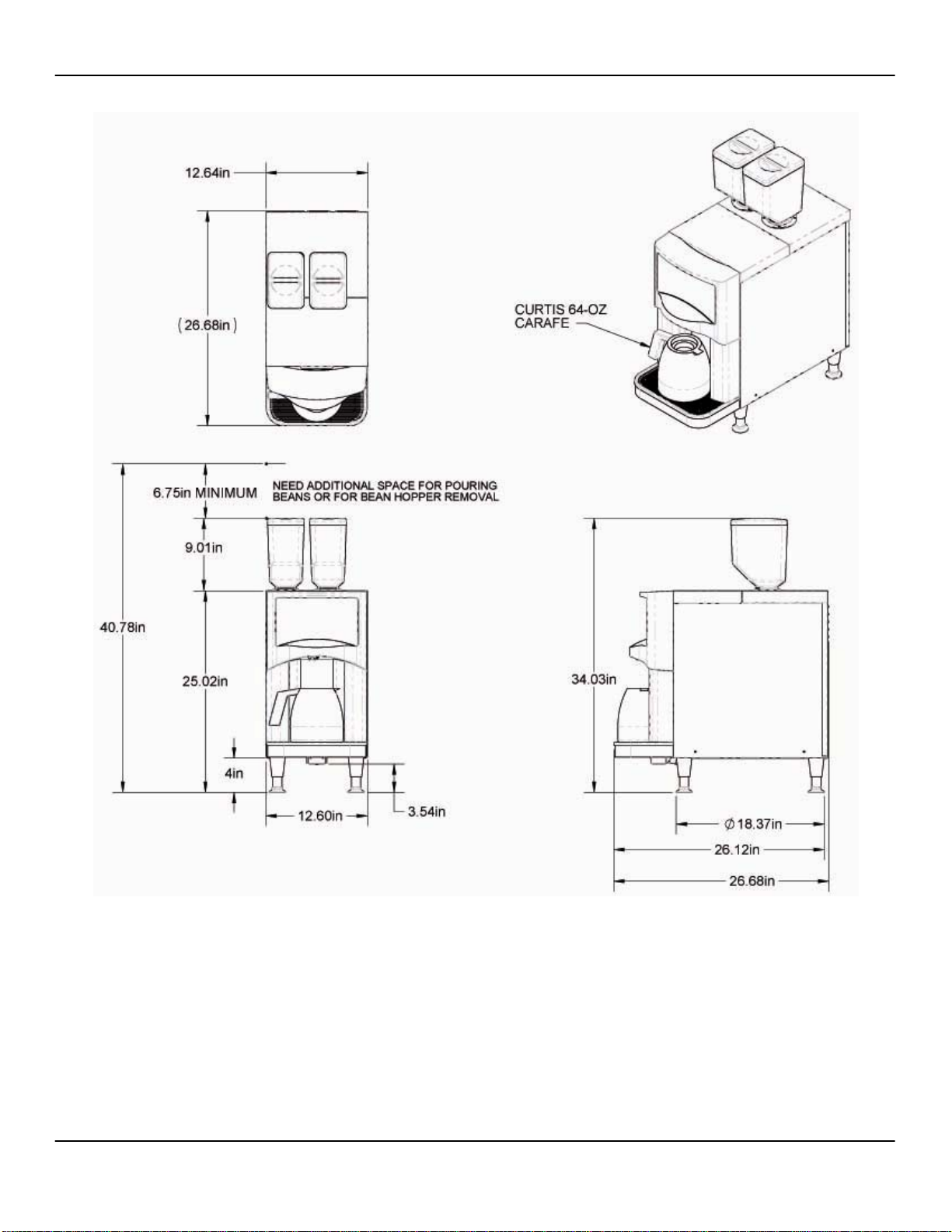
Overall Space
13” W x 27” D x 34” H
33cm W x 69cm D x 86cm H
Drain
Connection for 3/4” ID drain dose
Indirect drain required
Located within five feet (1.5 meters) of machine
Power and Water Requirements
Power
Located within five feet (1.5 meters) of machine
208Vac, 30amp
Water
Cold water source with a female 3/8” tube fitting and a
shut-off valve located behind the machine.
Water Pressure
Minimum: 25psi; Maximum: 100psi
25 gallons per hour (95 liters per hour)
A fresh water bypass is required for sites with a reverse
osmosis filter system.
Water Treatment System
A water treatment system must be used with the Ascent
Brewer.
25 gallons per hour (95 liters per hour)
2-2 Concordia Ascent Technical Support Manual
2900-331
3035-002A Section 2: Installation
Dimensions
Concordia Ascent Technical Support Manual 2-3
2900-331
Section 2: Installation 3035-002A
Installation
Plumbing
Only a qualified plumber complying with all local codes and requirements
can install the drain at the site. You are responsible for connecting the
machine to the drain.
The following requirements must be met:
• Drain accommodating a 3/4" (1.9cm) ID drain hose
• Drain must be located within five feet (1.5 meters) of machine
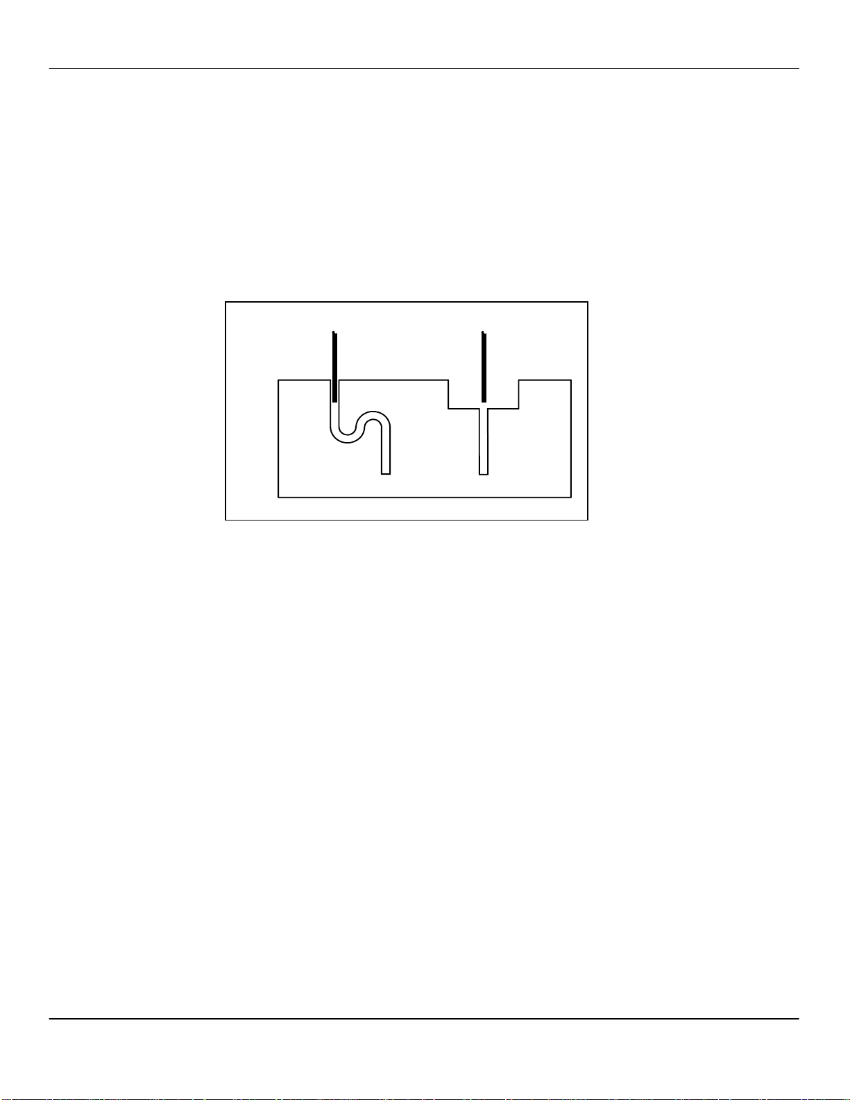
Approved Drain Configurations
DRAIN HOSE
FROM MACHINE
INDIRECT
DRAIN
DRAIN HOSE
FROM MACHINE
FLOOR SINK
DRAIN
The minimum rate of fall required is 1” (2.54cm) per foot, and the drain
hose must have a continuous rate of fall. Ensure the drain hose is
connected to the machine drain port.
If the drain has any low spots or any horizontal runs as it travels from the
machine to the drain, water and other waste from the machine will back
up and cause the drain hose and/or the drain tray to clog.
NOTE: When water and drain lines are connected, check for leaks.
Water Supply
To ensure proper operation of the machine, the following requirements
must be met:
• Cold water source with a shut-off valve and female 1/4" or 3/8”
fitting
• Water pressure: minimum 25psi; maximum 100psi
• Water source must be located within five feet (1.5 meters) of
machine
Problems with Reverse Osmosis Water System
A fresh water bypass is required for sites with a reverse osmosis filter
system. The machine water level sensors are inoperative when used
with this system.
2-4 Concordia Ascent Technical Support Manual
2900-331

3035-002A Section 2: Installation
Additional Tasks Required at Installation
Power Up the Machine
1. Ensure the electrical cord is plugged in.
2. Ensure water is supplied to unit and the water inlet valv e is open.
3. Ensure the unit is connected to a drain.
4. Ensure that the grounds bin is in place and the top panel is
closed.
5. Start the unit by turning on the main power switch located on
back left side of the Brewer.
6. Warm-up takes approximately 10 minutes.
NOTE: The grounds bin must be fully pushed into the machine.
Install Bean Hoppers
1. Install both bean hoppers.
2. Fill each bean hopper with the coffee beans associated with that
bean hopper button on the operator panel.
NOTE: The left bean hopper holds decaffeinated coffee beans
and the right bean hopper holds regular coffee beans.
IMPORTANT: Ensure the hopper stoppers are removed, so that the
beans are delivered to the grinder.
Concordia Ascent Technical Support Manual 2-5
2900-331

Section 2: Installation 3035-002A
Page Intentionally Left Blank
2-6 Concordia Ascent Technical Support Manual
2900-331

Section 3 :: Electrical
1. Electrical System Overview
2. AC Block Diagram
3. I/O Harness Board Schematic
4. DC Power Supply Schematic
TECHNICAL SUPPORT
Section 3: Electrical 3035-003A
Electrical System Overview
Machine Operating Voltage
The minimum electrical requirements must be met to ensure proper
operation of machine:
• 208Vac
• Single Phase: 30amp dedicated circuit
• NEMA 14-30/30amp four-prong 250Vac plug
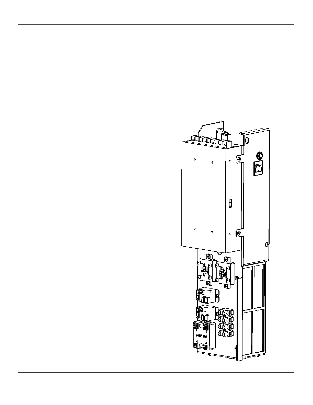
Electrical Tower
Located in the back of the machine behind the left grinder, the electrical
tower houses:
• Power Switch
• Circuit Breaker
• DC Power Supply
• Rear Input/Output Control Board
• A/C Power Relays
• Hot Water Heater Solid State Relay
• Grinder Solid State Relays
• Water Pump Relay
3-2 Concordia Ascent Technical Support Manual
2900-331
3035-003A Section 3: Electrical
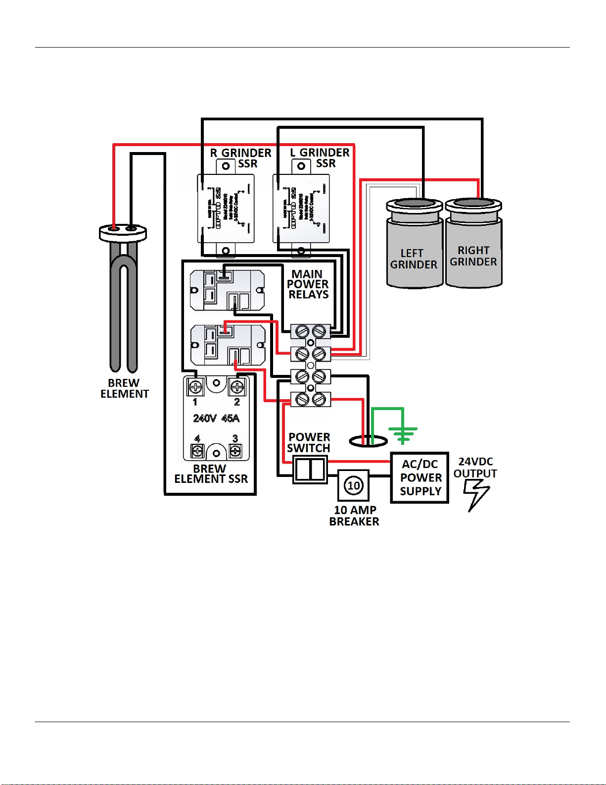
AC Block Diagram
Concordia Ascent Technical Support Manual 3-3
2900-331
Section 3: Electrical 3035-003A
Section 3: Electrical 3035-003A
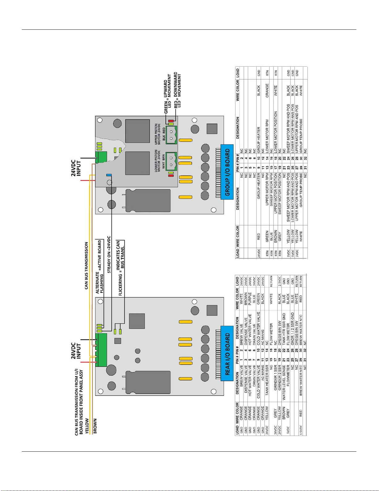
I/O Harness Board Diagram
3-4 Concordia Ascent Technical Support Manual
3-4 Concordia Ascent Technical Support Manual
2900-331
2900-331
 Loading...