


XPRESS
Technician’s Manual
Concordia Coffee Systems
1287 120th Avenue NE
Bellevue, WA 98005 (425) 453-2800 (800) 778-0990
(425) 453-2167 Fax
http://www.concordiacoffee.com/
Technical Writer and Editor: Shana McKibbin
Technical Support: Gary Williams, Gery Jaggars, Chris Collier, Dana Klatt, Allen Moore, Dave Davis
Graphic Engineers: Dan Gilbert, Quan Nguyen
Edition: December, 2012 2900-300B
Revision Change Log
|
Replace |
|
|
With New |
|
|
Brief Description |
|
|
Date |
|
|
XXX |
|
|
Old Section |
|
|
Section |
|
|
|
|
|
|
Revision |
|
||
|
|
|
|
|
|
|
|
|
|
|
|
|||
|
|
|
|
|
|
|
|
|
|
|
|
|
|
|
|
|
|
|
|
|
|
|
|
|
|
|
|
|
|
|
|
|
|
|
|
|
|
|
|
|
|
|
|
|
|
|
|
|
|
|
|
|
|
|
|
|
|
|
|
|
|
|
|
|
|
|
|
|
|
|
|
|
|
|
|
|
|
|
|
|
|
|
|
|
|
|
|
|
|
|
|
|
|
|
|
|
|
|
|
|
|
|
|
|
|
|
|
|
|
|
|
|
|
|
|
|
|
|
|
|
|
|
|
|
|
|
|
|
|
|
|
|
|
|
|
|
|
|
|
|
|
|
|
|
|
|
|
|
|
|
|
|
|
|
|
|
|
|
|
|
|
|
|
|
|
|
|
|
|
|
|
|
|
|
|
|
|
|
|
|
|
|
|
|
|
|
|
|
|
|
|
|
|
|
|
|
|
|
|
|
|
|
|
|
|
|
|
|
|
|
|
|
|
|
|
|
|
|
|
|
|
|
|
|
|
|
|
|
|
|
|
|
|
|
|
|
|
|
|
|
|
|
|
|
|
|
|
|
|
|
|
|
|
|
|
|
|
|
|
|
|
|
|
|
|
|
|
|
|
|
|
|
|
|
|
|
|
|
|
|
|
|
|
|
|
|
|
|
|
|
|
|
|
|
|
|
|
|
|
|
|
|
|
|
|
|
|
|
|
|
|
|
|
|
|
|
|
|
|
|
|
|
|
|
|
|
|
|
|
|
|
|
|
|
|
|
|
|
|
|
|
|
|
|
|
|
|
|
|
|
|
|
|
|
|
|
|
|
|
|
|
|
|
|
|
|
|
|
|
|
|
|
|
|
|
|
|
|
|
|
|
|
|
|
|
|
|
|
|
|
|
|
|
|
|
|
|
|
|
|
|
|
|
|
|
|
|
|
|
|
|
|
|
|
|
|
|
|
|
|
|
|
|
|
|
|
|
|
|
|
|
|
|
|
|
|
|
|
|
|
|
|
|
|
|
|
|
|
|
|
|
|
|
|
|
|
|
|
|
|
|
|
|
|
|
|
|
|
|
|
|
|
|
|
|
|
|
|
|
|
|
|
|
|
|
|
|
|
|
|
|
|
|
|
Table of Contents
Section 1 :: Xpress Overview ...................................................................... |
1-1 |
Xpress Overview ................................................................................................. |
1-2 |
Xpress Components............................................................................................ |
1-3 |
Flavor System Overview ..................................................................................... |
1-4 |
Flavor System Components................................................................................ |
1-5 |
Section 2 :: Installation and Removal ....................................................... |
2-1 |
Technical Specifications and Site Requirements................................................ |
2-2 |
Machine Dimensions........................................................................................... |
2-3 |
Installation ........................................................................................................... |
2-4 |
Configuring the Machine for Supply Voltage................................. |
2-4 |
Espresso Machine Electrical Settings ........................................... |
2-4 |
Setting the DC Jumper Plug.......................................................... |
2-4 |
Configuring Transformer Auxiliary Connector #1 .......................... |
2-5 |
Plumbing ............................................................................................................. |
2-6 |
Connecting the External Drain ...................................................... |
2-6 |
Water Supply ................................................................................. |
2-6 |
Problems with Reverse Osmosis Water System........................... |
2-7 |
Flavor System ..................................................................................................... |
2-7 |
Flavor System Installation ............................................................. |
2-7 |
Prime the Flavor System ............................................................... |
2-7 |
Chocolate Sauce ........................................................................... |
2-7 |
Verify Flavor Pour Rate ................................................................. |
2-7 |
Additional Tasks Required at Installation............................................................ |
2-8 |
Power Up the Machine .................................................................. |
2-8 |
Install Bean Hoppers ..................................................................... |
2-8 |
Install Cup Stand (Optional) .......................................................... |
2-8 |
Operational Configuration ................................................................................... |
2-8 |
Placing Milk in the Refrigeration Unit ............................................ |
2-8 |
Machine Calibration ............................................................................................ |
2-9 |
Customer Training............................................................................................... |
2-9 |
Installation Checklist ........................................................................................... |
2-9 |
Removal Procedures........................................................................................... |
2-9 |
Section 3 :: Electrical................................................................................. |
3-1 |
Electrical Block Diagram ..................................................................................... |
3-2 |
Fuses .................................................................................................................. |
3-3 |
Backplane ........................................................................................................... |
3-4 |
AC Drawer Assembly .......................................................................................... |
3-5 |
DC Board Assembly............................................................................................ |
3-6 |
CPU Board .......................................................................................................... |
3-7 |
J4................................................................................................... |
3-8 |
J2................................................................................................... |
3-8 |
P3 .................................................................................................. |
3-9 |
P4 .................................................................................................. |
3-9 |
Peripheral Connections Configuration .............................................................. |
3-10 |
Transformer....................................................................................................... |
3-11 |
Power Into the Machine .................................................................................... |
3-15 |
DC Power Supply Board LEDs ......................................................................... |
3-18 |
Heating Element Wiring Diagrams.................................................................... |
3-20 |
Jumper Plug Connector Detail .......................................................................... |
3-21 |
Section 4 :: Software.................................................................................. |
4-1 |
Software Overview .............................................................................................. |
4-2 |
Software Menu Informational Screens .......................................... |
4-2 |
Categories ..................................................................................... |
4-2 |
Service Switch..................................................................................................... |
4-3 |
Navigating the Software Menu ...................................................... |
4-4 |
Accessing a Sub-Category............................................................ |
4-4 |
Exiting the Menu System............................................................... |
4-5 |
Accessing the Grand Total Drink Count ........................................ |
4-5 |
Accessing Total Drink Count Statistics ......................................... |
4-5 |
Accessing Daily Drink Count Statistics ......................................... |
4-5 |
Software Quick Reference Table ........................................................................ |
4-6 |
Calibration ......................................................................................................... |
4-13 |
Calibrating Pump Pressure ......................................................... |
4-14 |
Calibrating Espresso ................................................................... |
4-14 |
Configuring the Bean Hoppers .................................................... |
4-14 |
Espresso Extraction and Temperature Parameters .................... |
4-15 |
Drink Temperatures..................................................................... |
4-15 |
Verifying Espresso Extraction ..................................................... |
4-15 |
Calibrating Milk Timings .............................................................. |
4-16 |
Calibrating Brewed Coffee .......................................................... |
4-16 |
Calibrating Flavor Timings........................................................... |
4-17 |
Espresso Extraction Pre-Treatment Options .................................................... |
4-17 |
Pre-Treatment Options ................................................................ |
4-17 |
CPU Board ........................................................................................................ |
4-19 |
Loading New Software to a Machine ................................................................ |
4-20 |
Required Equipment.................................................................... |
4-20 |
Configuring HyperTerminal ......................................................... |
4-20 |
Connecting a Laptop to a Machine ............................................. |
4-27 |
Updating Software for Customers with Custom Drink Recipes... |
4-30 |
Section 5 :: Plumbing ................................................................................ |
5-1 |
The Water System .............................................................................................. |
5-2 |
Line Pressure ................................................................................ |
5-3 |
Check Valve .................................................................................. |
5-3 |
Water Filtration System ................................................................. |
5-3 |
Hot Water Tank ................................................................................................... |
5-4 |
Temperature/Level Probe.............................................................. |
5-5 |
Level Probe ................................................................................... |
5-5 |
Temperature Probe ....................................................................... |
5-6 |
Pressure Relief Valve .................................................................... |
5-6 |
High Temperature Limit Switch ..................................................... |
5-6 |
Water Inlet ..................................................................................... |
5-6 |
Flowmeter...................................................................................... |
5-7 |
Heating Elements .......................................................................... |
5-7 |
Brew Valve .................................................................................... |
5-7 |
Hot Water Valve ............................................................................ |
5-7 |
Draining the Hot Water Tank......................................................... |
5-8 |
Water Pump and Motor ....................................................................................... |
5-8 |
Water Pressure Gauge.................................................................. |
5-9 |
Setting Pump Pressure ................................................................. |
5-9 |
Expansion Valve............................................................................ |
5-9 |
Check Water Flow Message ......................................................... |
5-9 |
The Steam System............................................................................................ |
5-10 |
Steam Tank – Front View............................................................ |
5-10 |
Steam Tank – Rear View ............................................................ |
5-11 |
Steam Tank Fill Valve ................................................................. |
5-12 |
Steam Tank ................................................................................. |
5-12 |
Water Level Probes ..................................................................... |
5-12 |
Pressure Gauge .......................................................................... |
5-13 |
Heating Elements ........................................................................ |
5-13 |
Pressure Relief Valve .................................................................. |
5-13 |
High Temperature Limit Switch ................................................... |
5-13 |
Steam Valves .............................................................................. |
5-14 |
Left Steam Valve ......................................................................... |
5-14 |
Center Steam Valve .................................................................... |
5-15 |
Right Steam Valve....................................................................... |
5-15 |
Air Purge Process ....................................................................... |
5-15 |
Captive Water Purge System ...................................................... |
5-15 |
Draining the Steam Tank............................................................. |
5-15 |
Section 6 :: Coffee System ......................................................................... |
6-1 |
The Coffee System ............................................................................................. |
6-2 |
Espresso Path ............................................................................... |
6-2 |
Grinders .............................................................................................................. |
6-3 |
Double Grinder Assembly ............................................................. |
6-3 |
Calibration: Espresso Grind .......................................................... |
6-4 |
Grinder Adjustment Panel ............................................................. |
6-4 |
Grinder Adjustment Diagram......................................................... |
6-5 |
Measuring the Coffee Powder Dose ............................................. |
6-5 |
Coffee Powder Channel ................................................................ |
6-6 |
Removing the Grinder ................................................................... |
6-6 |
Replacing the Grinder Burrs/Blades.............................................. |
6-7 |
Setting the Grinder Adjustment Indicator to Mid-Scale ................. |
6-7 |
Bean Hoppers ..................................................................................................... |
6-8 |
Filling a Bean Hopper .................................................................... |
6-8 |
Inserting the Hopper Stopper ........................................................ |
6-8 |
Removing a Bean Hopper ............................................................. |
6-8 |
Brew Group ......................................................................................................... |
6-9 |
Brew Group Initialization ............................................................. |
6-10 |
Brew Group Components ................................................................................. |
6-10 |
Hall-Effect Sensors...................................................................... |
6-11 |
Left Piston.................................................................................... |
6-12 |
Right Piston ................................................................................. |
6-12 |
Piston Movement......................................................................... |
6-12 |
Viewing the Left Piston Movement .............................................. |
6-13 |
Removing the Left Piston ............................................................ |
6-13 |
Removing the Right Piston.......................................................... |
6-14 |
Gearbox Removal and Installation.................................................................... |
6-15 |
Removing the Gearbox ............................................................... |
6-15 |
Installing the Gearbox ................................................................. |
6-16 |
Section 7 :: Milk System and Refrigeration Unit ...................................... |
7-1 |
The Milk Delivery System ................................................................................... |
7-2 |
Milk Delivery System Components ..................................................................... |
7-2 |
Milk Pump Assembly ..................................................................... |
7-2 |
Milk Pick-Up Tube ......................................................................... |
7-2 |
Milk Pump...................................................................................... |
7-2 |
Milk System Theory of Operation........................................................................ |
7-3 |
Basic Terminology ......................................................................... |
7-3 |
Initial Setup of the Milk System ..................................................... |
7-4 |
Milk System Capabilities ............................................................... |
7-5 |
A Common Milk Timing Mistake.................................................... |
7-5 |
Air Gate Valve Assembly .................................................................................... |
7-5 |
Air Gate Valves ............................................................................. |
7-6 |
Air Purge Valves............................................................................ |
7-6 |
Air Vent Needles ........................................................................... |
7-6 |
Connection of Milk Pump Assembly and Air Gate Valve Assembly7- |
|
6 |
|
Alt Milk Valve....................................................................................................... |
7-6 |
Steam Delivery Components .............................................................................. |
7-7 |
Steam Valves ................................................................................ |
7-7 |
Mixing TEE Assembly ................................................................... |
7-7 |
Refrigeration Unit Overview ................................................................................ |
7-8 |
Placing Milk in the Machine........................................................... |
7-9 |
Checking the Refrigeration Unit Temperature............................... |
7-9 |
Refrigeration Cooling Module Assembly ..................................... |
7-10 |
Fan Control Board ....................................................................... |
7-11 |
Cold Sink Deflector...................................................................... |
7-11 |
Interior Circulation Fan Assembly ............................................... |
7-12 |
Exterior Cooling Module Fan Assembly ...................................... |
7-12 |
Temperature Probe Assembly..................................................... |
7-12 |
Milk Weight Trays ........................................................................ |
7-13 |
Adjusting a Milk Weight Tray....................................................... |
7-15 |
Milk Level Sensors ...................................................................... |
7-16 |
Auto Milk Select........................................................................... |
7-16 |
Section 8 :: Steam Wands ......................................................................... |
8-1 |
Steam Wand Overview ....................................................................................... |
8-2 |
Automatic Steam Wand ...................................................................................... |
8-2 |
Automatic Steam Wand Theory of Operation ............................... |
8-2 |
Automatic Steam Wand Selections ............................................... |
8-3 |
Automatic Steam Wand Programming.......................................... |
8-4 |
Air Pump........................................................................................ |
8-4 |
Steam and Vacuum Valve Assembly ............................................ |
8-4 |
Automatic Steam Wand Wiring ........................................................................... |
8-5 |
Replacing an Automatic Steam Wand ................................................................ |
8-5 |
Manual Steam Wand........................................................................................... |
8-6 |
Replacing a Manual Steam Wand ...................................................................... |
8-6 |
Removing a Steam Wand ............................................................. |
8-8 |
Installing a Steam Wand ..................................................................................... |
8-8 |
Cleaning a Steam Wand ..................................................................................... |
8-8 |
Section 9 :: Flavor System ......................................................................... |
9-1 |
The Flavor System .............................................................................................. |
9-2 |
Chocolate Sauce Delivery Path..................................................... |
9-2 |
Syrup Delivery Path....................................................................... |
9-3 |
Flavor Tubes.................................................................................. |
9-3 |
Flavor Storage Area ...................................................................... |
9-4 |
Chocolate Sauce ........................................................................... |
9-4 |
Chocolate Heater Assembly.......................................................... |
9-4 |
Connecting Flavor Tubing ............................................................. |
9-4 |
Changing the Flavor Pour Rate..................................................... |
9-5 |
Verifying Proper Syrup Flow.......................................................... |
9-6 |
Changing Flavor Boxes ................................................................. |
9-7 |
Peristaltic Pumps ................................................................................................ |
9-8 |
Syrup Manifold .................................................................................................... |
9-8 |
Chocolate Rinse Purge Valve ....................................................... |
9-9 |
Milk Bowl ....................................................................................... |
9-9 |
Removing the Syrup Manifold ....................................................... |
9-9 |
Replacing the Syrup Manifold ..................................................... |
9-10 |
Cleaning the Flavor Delivery System................................................................ |
9-10 |
Priming the Flavor Delivery System.................................................................. |
9-12 |
Section 10 :: Vending............................................................................... |
10-1 |
Vending Overview ............................................................................................. |
10-2 |
Vending Backpack....................................................................... |
10-2 |
Replacing a Card Reader ................................................................................. |
10-2 |
Installing a Vending Unit ................................................................................... |
10-3 |
Removing a Vending Unit ................................................................................. |
10-3 |
Troubleshooting ................................................................................................ |
10-3 |
Section 11 :: Cleaning and Maintenance .................................................. |
11-1 |
Daily Maintenance............................................................................................. |
11-2 |
Concordia Cleaning Products...................................................... |
11-2 |
Cleaning Timers ................................................................................................ |
11-3 |
Preventive Maintenance ................................................................................... |
11-3 |
Section 12 :: Concordia Procedures ........................................................ |
12-1 |
Service Call Process ......................................................................................... |
12-2 |
Arrival to Site ............................................................................... |
12-2 |
Machine Repair ........................................................................... |
12-2 |
Hold for Parts Procedures ........................................................... |
12-2 |
Departing from Site ..................................................................... |
12-2 |
Required Immediately for Call Closeout...................................... |
12-3 |
Complete Call Protocol ..................................................................................... |
12-3 |
Machine Appearance .................................................................. |
12-3 |
Milk System ................................................................................. |
12-3 |
Brew Group ................................................................................. |
12-3 |
Water Tank .................................................................................. |
12-3 |
Water Pump................................................................................. |
12-3 |
Steam Tank ................................................................................. |
12-3 |
Refrigeration Unit ........................................................................ |
12-4 |
Espresso Extraction .................................................................... |
12-4 |
Milk Pour...................................................................................... |
12-4 |
Service Call Checklist ....................................................................................... |
12-5 |
Parts Return Policy ........................................................................................... |
12-6 |
Non-Consignment Agents ........................................................... |
12-6 |
Consignment Agents ................................................................... |
12-6 |
Return Material Tag..................................................................... |
12-7 |
Parts Replenishment Form ............................................................................... |
12-8 |
Section 13 :: Customer Service and Training .......................................... |
13-1 |
Training the Customer....................................................................................... |
13-2 |
User Guide .................................................................................. |
13-2 |
Starting and Resetting the Machine ............................................ |
13-2 |
Filling Machine with Beans and Milk ........................................... |
13-2 |
Pouring Drinks and Cancelling Drinks......................................... |
13-2 |
Restocking and Changing Flavor Boxes ..................................... |
13-2 |
Cleaning ...................................................................................... |
13-3 |
Serial Number ............................................................................. |
13-3 |
Accessing Software Menu........................................................... |
13-3 |
Troubleshooting Tips ................................................................... |
13-3 |
Contacting Concordia for Assistance .......................................... |
13-4 |
Concordia Beverage Systems’ Value-Added Service....................................... |
13-5 |
Value-Added Service................................................................... |
13-6 |
G.U.E.S.T.......................................................................................................... |
13-7 |
Greet the Customer..................................................................... |
13-7 |
Understand your Customer ......................................................... |
13-8 |
Empathize with Your Customer................................................... |
13-9 |
Solve the Problem ..................................................................... |
13-10 |
Train the Customer.................................................................... |
13-10 |
Section 14 :: Messages ............................................................................. |
14-1 |
Troubleshooting Display Messages .................................................................. |
14-2 |
Section 15 :: Troubleshooting................................................................... |
15-1 |
Troubleshooting Quick Reference Guide.......................................................... |
15-2 |
Machine Failure ........................................................................... |
15-2 |
Coffee System ............................................................................. |
15-3 |
Flavor System ............................................................................. |
15-3 |
Milk System ................................................................................. |
15-4 |
Troubleshooting Trees ...................................................................................... |
15-5 |
Brew System: Right Drive Timeout ............................................. |
15-6 |
Brew System: Invalid Stop L ....................................................... |
15-7 |
Brew System: Invalid Stop R....................................................... |
15-9 |
Brew System: Left Drive Timeout.............................................. |
15-11 |
Grinder System: Out of Beans .................................................. |
15-13 |
Milk System: Overpouring Milk.................................................. |
15-15 |
Milk System: Cold Milk Pour...................................................... |
15-17 |
Milk System: No Milk Pour ........................................................ |
15-19 |
Milk System: Short Milk Pour .................................................... |
15-21 |
Refrigeration System: Temperature Above 40˚F ...................... |
15-23 |
Steam System: Steam Temperature High ................................ |
15-25 |
Steam System: Check Sensor Voltage ..................................... |
15-26 |
Steam System: Check Steam Probes ....................................... |
15-27 |
Steam System: Check Steam Tank .......................................... |
15-28 |
Steam System: Steam Temperature Low ................................. |
15-29 |
Water System: Water Temperature Too High........................... |
15-30 |
Water System: Water Temperature Too Low............................ |
15-31 |
Water System: Check Water Supply ......................................... |
15-33 |
Water System: Water Tank Limit Switch Open ......................... |
15-35 |
Flavor System: Cross-Contamination of Syrup Lines ............... |
15-37 |
Flavor System: Too Much Flavor in Drink ................................. |
15-38 |
Flavor System: Not Enough Flavor in Drink .............................. |
15-39 |
Flavor System: No Flavor in Drink ............................................ |
15-41 |
Electrical System: Check Analog Board.................................... |
15-43 |
Electrical System: Incorrect Software for Touchpad ................. |
15-44 |
Electrical System: Milk Pump Running Continuously ............... |
15-45 |
Electrical System: Front Panel Failed ....................................... |
15-46 |
Electrical System: Check Clock................................................. |
15-47 |
Electrical System: Check Stats ................................................. |
15-48 |
Electrical System: CPU Load Disp and Seq Error .................... |
15-49 |
Electrical System: AC Voltage Error ......................................... |
15-51 |
Electrical System: DC Voltage Failure ...................................... |
15-53 |
Vending System: Card Swipe or Tap Not Authorized ............... |
15-55 |
Vending System: Not Configured .............................................. |
15-56 |
Vending System: No Display on Card Reader .......................... |
15-57 |
Section 16 :: Parts Lists & Diagrams ....................................................... |
16-1 |
Recommended Tools List ................................................................................. |
16-2 |
Standard Tools ............................................................................ |
16-2 |
Concordia Stocked Tools ............................................................ |
16-2 |
Consumables .............................................................................. |
16-2 |
Parts Lists and Diagrams .................................................................................. |
16-3 |
Diagram 1: Machine Overview .................................................... |
16-4 |
Diagram 1, Parts List: Machine Overview ................................... |
16-5 |
Diagram 2: Grounds Bin Door, Refrigerator Door with Hot Water |
|
Button Assembly ......................................................................... |
16-6 |
Diagram 2, Parts List: Refrigerator Door with Hot Water Button
Assembly ..................................................................................... |
16-7 |
Diagram 3: Refrigerator Door with Steam Wand Assembly........ |
16-8 |
Diagram 3, Parts List: Refrigerator Door with Steam Wand |
|
Assembly ..................................................................................... |
16-9 |
Diagram 4: Front Panel ............................................................. |
16-10 |
Diagram 4, Parts List: Front Panel ............................................ |
16-11 |
Diagram 5: Top Panel ............................................................... |
16-12 |
Diagram 5, Parts List: Top Panel .............................................. |
16-13 |
Diagram 6: Grinder Assembly ................................................... |
16-14 |
Diagram 6, Parts List: Grinder Assembly .................................. |
16-15 |
Diagram 7: Grinder Adjustment Assembly ................................ |
16-16 |
Diagram 7, Parts List: Grinder Adjustment Assembly ............... |
16-17 |
Diagram 8: Group Upper and Lower Piston Assembly ............. |
16-18 |
Diagram 8, Parts List: Group Upper and Lower Piston Assembly 16- |
|
19 |
|
Diagram 9: Group Drive System ............................................... |
16-20 |
Diagram 9, Parts List: Group Drive System .............................. |
16-21 |
Diagram 10: Milk Pump Assembly ............................................ |
16-22 |
Diagram 10: Parts List, Milk Pump Assembly ........................... |
16-23 |
Diagram 11: Product Delivery Assembly, Xpress 6 .................. |
16-24 |
Diagram 11, Parts List: Product Delivery Assembly, Xpress 6 .16-25 |
|
Diagram 12: Product Delivery Assembly, Xpress 0 .................. |
16-26 |
Diagram 12, Parts List: Product Delivery Assembly, Xpress .... |
16-27 |
Diagram 13: Refrigeration Unit Assembly ................................. |
16-28 |
Diagram 13, Parts List: Refrigeration Unit Assembly................ |
16-29 |
Diagram 14: Chocolate Sauce Delivery System ....................... |
16-30 |
Diagram 14, Parts List: Chocolate Sauce Delivery System ...... |
16-31 |
Diagram 15: Syrup Delivery System ......................................... |
16-32 |
Diagram 15, Parts List: Syrup Delivery System ........................ |
16-33 |
Diagram 16: Refrigeration Unit Cooling Assembly.................... |
16-34 |
Diagram 16, Parts List: Refrigeration Unit Cooling Assembly... |
16-35 |
Diagram 17: Steam Tank, Front ................................................ |
16-36 |
Diagram 17, Parts List: Steam Tank, Front............................... |
16-37 |
Diagram 18: Steam Tank, Rear ................................................ |
16-38 |
Diagram 18, Parts List: Steam Tank, Rear ............................... |
16-39 |
Diagram 19: Water Pump and Motor ........................................ |
16-40 |
Diagram 19, Parts List: Water Pump and Motor ....................... |
16-41 |
Diagram 20: Hot Water Tank..................................................... |
16-42 |
Diagram 20, Parts List: Hot Water Tank ................................... |
16-43 |
Diagram 21: Water/Steam Gauge/ Air Valve Assembly............ |
16-44 |
Diagram 21: Parts List: Water/Steam Gauge/Air Valve Assembly16- |
|
45 |
|
Diagram 22, Parts List: Drain Valve Bridge Web Assembly ..... |
16-46 |
Diagram 22, Parts List: Drain Valve Bridge Web Assembly ..... |
16-47 |
Section 17 :: Index .................................................................................... |
17-1 |
Page Intentionally Left Blank
Page Intentionally Left Blank

Section 1 :: Xpress
Overview
1.Xpress Overview
2.Xpress Components
3.Flavor System Overview
4.Flavor System Components
T E C H N I C A L S U P P O R T
Section 1: Xpress Overview |
3033-001B |
Xpress Overview
1-2 |
Concordia Xpress Technical Support Manual |
2900-300B

3033-001B |
Section 1: Xpress Overview |
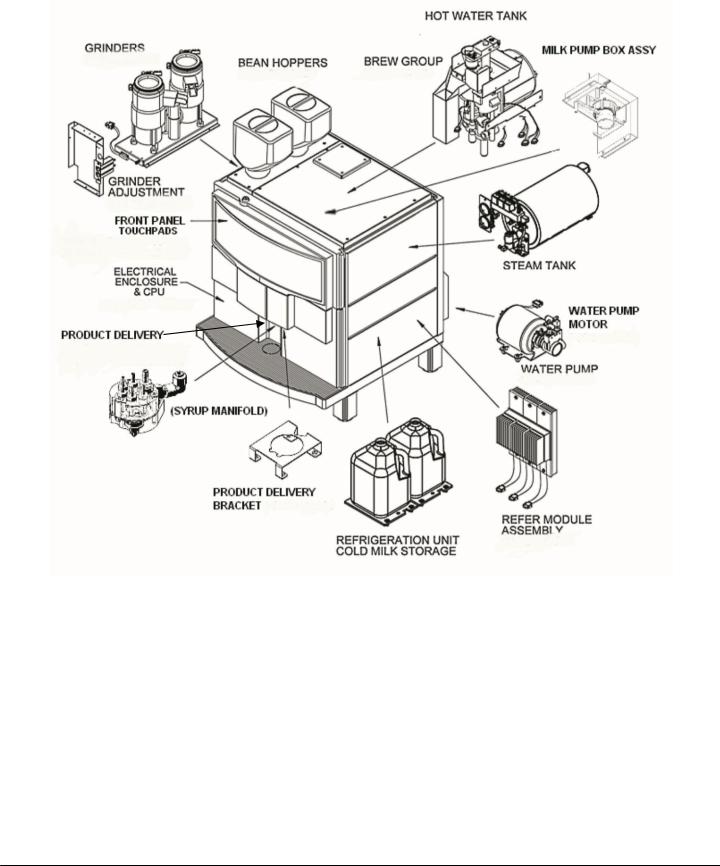
Xpress Components
Front Panel Touch Pad
The front panel touch pad provides a user interface for selecting and pouring drinks.
Electrical Enclosure and CPU
The electrical enclosure houses the CPU, AC drawer, and DC board.
Bean Hoppers
Each bean hopper holds whole espresso roast beans and feeds the beans to the grinders.
Water Pump and Motor
The water pump regulates the water pressure to 135-140psi during the espresso extraction process. The motor supplies power to the pump.
Hot Water Tank
The hot water tank stores and heats the water used to brew espresso.
Brew Group
The brew group assembly brews espresso and automatically discards the used coffee into the grounds bin.
Steam Tank
The steam tank provides steam used for steaming the milk.
Grinders and the Grinder Adjustment Assembly
The grinders are calibrated to grind espresso beans according to the customer’s recipe. The grinder adjustment assembly changes the grind of espresso beans.
Exhaust Fan
NOT SHOWN
The exhaust fan removes excess heat build-up from the machine interior.
Refrigeration Unit
The refrigeration unit stores the milk used for drinks.
Refrigeration Module Assembly
The refrigeration module assembly regulates the temperature inside the refrigeration unit.
Milk Pump and Milk Pump Box Assembly
The milk pump assembly draws milk from the milk container.
Syrup Manifold
Xpress 6 only
Flavor is infused into drinks via the syrup manifold.
Product Delivery Bracket
The product delivery bracket holds the milk bowl (not shown) and the syrup manifold.
Product Delivery Nozzle
The finished drink is poured through the product delivery nozzle and into the customer’s cup.
Concordia Xpress Technical Support Manual |
1-3 |
2900-300B
Section 1: Xpress Overview |
3033-001B |
Flavor System Overview
CHOCOLATE HEATER
ASSEMBLY
1-4 |
Concordia Xpress Technical Support Manual |
2900-300B

3033-001B |
Section 1: Xpress Overview |
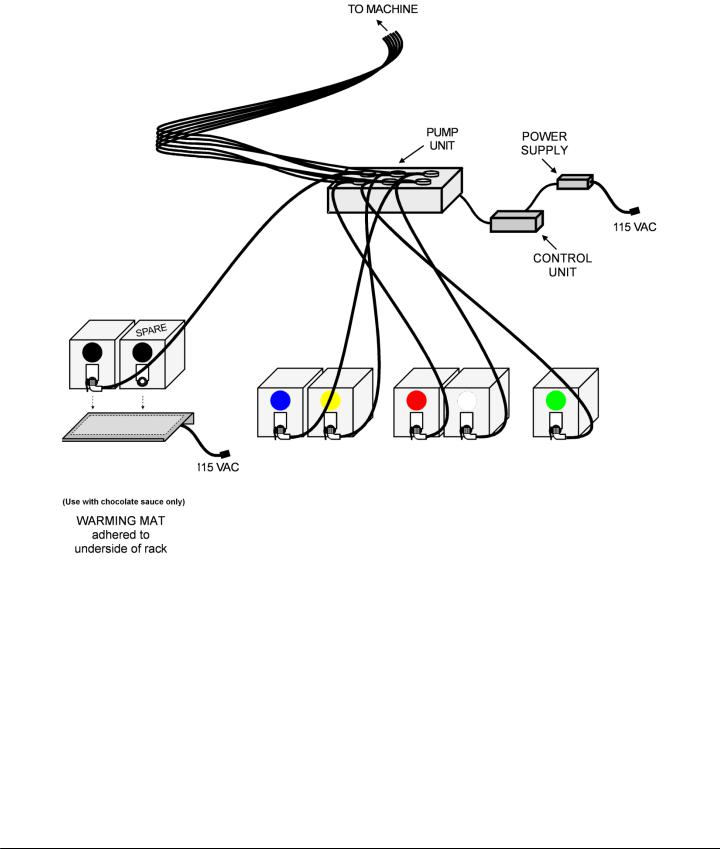
Flavor System Components
Xpress 6 only
Pump Unit
The pump unit contains the six peristaltic pump assemblies that move the flavors from the boxes to the syrup manifold, and then to the product delivery outlet.
Control Unit
The control unit houses the electronic board that controls the syrup pumps.
Power Supply
The power supply provides 24Vdc power to the control unit.
Chocolate Heater Assembly
The chocolate heater assembly provides heat to the chocolate sauce, to ensure a minimum temperature of 85°F (29.4°C) is maintained.
Concordia Xpress Technical Support Manual |
1-5 |
2900-300B

Section 1: Xpress Overview |
3033-001B |
Page Intentionally Left Blank
1-6 |
Concordia Xpress Technical Support Manual |
2900-300B

Section 2 :: Installation
and Removal
1.Technical Specifications and Site Requirements
2.Machine Dimensions
3.Installation
4.Plumbing
5.Flavor System
6.Additional Tasks Required at Installation
7.Operational Configuration
8.Machine Calibration
9.Customer Training
10.Installation Checklist
11.Removal Procedures
T E C H N I C A L S U P P O R T
Section 2: Installation and Removal |
|
|
3033-002B |
Technical |
Specifications |
and |
Site |
Requirements |
|
|
|
To ensure the site is ready, the customer is required to complete and return a pre-installation checklist. The customer is required to have electrical, water, and a drain located within a specified distance from the machine.
Technical Specifications
Weight: |
300lbs/137kg |
Operating Environment: |
55°- 85°F (13°-29°C) |
Power Consumption: |
24 amps @ 208Vac max |
|
8 amps @ 115Vac max |
Compliance: |
|
FCC: |
Part 15B, Class A, Part 68 |
UL Listed |
|
NSF Certified |
|
Location Requirements
Locate indoors only
Overall Space
23.79”W x 26.75”D x 36.13”H
59.64cm x 67.49cm x 91.44cm
Machine Counter Space
36”W x 29”D x 42”H
91.44cm x 73.66cm x 106.68cm
Flavor Delivery System
30”W x 30”D x 27”H
76.2cmWx76.2Dx68.6H
Drain
Connection for ¾”/1.9cm drain dose
Indirect drain required
Located within five feet/1.5 meters of machine
Power and Water Requirements
Power
Located within five feet (1.5 meters) of machine Single Phase:
200-240Vac, 30amp dedicated circuit NEMA L14-30 Receptacle
High Leg:
200-240Vac, 30amp, high leg dedicated circuit.
International machines are shipped without a power plug. A plug must be attached at the time of installation and meet with all local electrical codes.
Flavor Delivery System
Domestic
Chocolate Heater Assembly 115Vac, 15amp
NEMA 5-15P
Control Unit 115Vac, 15amp NEMA 5-15P
International
Chocolate Heater Assembly 230Vac
Control Unit 90-260Vac
Water
Cold water source with a 1/4” or 3/8” tube fitting with a shut-off valve, located within five feet (1.5 meters) of machine
Pressure
Minimum: 30psi; Maximum: 100psi (min: 2 bar, max 7 bar) 25 gallons per hour (95 liters per hour)
A fresh water bypass is required for sites with a reverse osmosis filter system
Scalex Water Treatment System
Included with the unit: two cartridges (one carbon, one softener)
25”H x 11”W x 5.25”D
63.5cmHx28cmWx13.34cmD
2-2 |
Concordia Xpress Technical Support Manual |
2900-300B
3033-002B |
Section 2: Installation and Removal |
Machine Dimensions
Concordia Xpress Technical Support Manual |
2-3 |
2900-300B
Section 2: Installation and Removal |
3033-002B |
Installation
Configuring the Machine for Supply Voltage
Before connecting machine to incoming power supply. The voltages.
the electrical supply, check and verify following chart displays the required
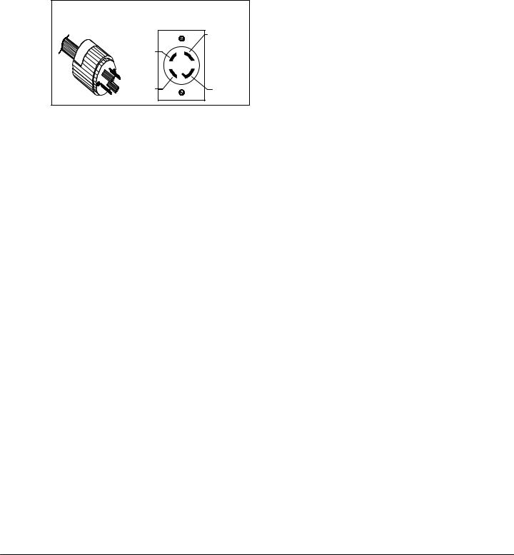
Plug and Receptacle – US only
IBS6+ Equipped ith 4 prong |
volt plug |
Xpress equipped with 4 prong |
208 volt plug |
|
L1 120VAC |
|
TO NEUTRAL |
NEUTRAL |
|
|
NEMA |
|
L1430-R |
L2 120VAC |
GROUND |
TO NEUTRAL |
|
Confirming Receptacle Voltages
Connections |
Voltage |
|
|
L1 to Ground |
110Vac – 120Vac |
|
|
L2 to Ground |
110Vac – 120Vac |
|
|
L1 to Neutral |
110Vac – 120Vac |
|
|
L2 to Neutral |
110Vac – 120Vac |
|
|
L1 to L2 |
200Vac – 240Vac |
|
|
Ground to Neutral |
0Vac |
|
|
Espresso Machine Electrical Settings
Prior to connecting the machine to the power source, verify the electrical settings are correct. The DC jumper plug and transformer must be properly configured.
WARNING: Failure to properly set the DC jumper plug and the transformer connector can result in machine malfunction, short circuit, blown fuses, overheating, or damage to circuit boards.
Setting the DC Jumper Plug
1.Measure the source voltage at the NEMA L1430-R receptacle (refer to the chart above). Record the value in the electrical section of the installation checklist.
2.Remove the electrical enclosure cover to access the DC power supply board.
CAUTION: ESD protection required.
3.Remove the DC power supply board using the white ejector
lever.
4.Use the diagram on the next page to configure the DC jumper plug to the measured source voltage.
5.Insert the free end of the yellow wire into the correct pinhole.
6.Insert the jumper plug into connector J1 located on the DC power supply board.
7.Re-install the DC power supply board. Ensure the board is fully seated by firmly pressing the board into connector on the backplane connector.
8.Re-install the electrical enclosure cover and verify the display cable is not stressed, pinched, or cut when front panel is lowered.
2-4 |
Concordia Xpress Technical Support Manual |
2900-300B
3033-002B |
Section 2: Installation and Removal |
|
Configuring the DC Jumper Plug |
200 VAC |
|
|
50-60Hz |
208 VAC |
200 VAC |
208 VAC |
|
|
220-240 VAC |
220-240 VAC

 L2
L2
L2
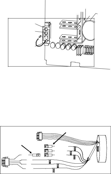
Configuring Transformer Auxiliary Connector #1
It may be necessary to configure the auxiliary connector at the transformer, depending on the measured supply voltage.
1.Remove the machine back panel.
2.Locate the transformer and connectors.
3.Using the voltage table, connect the transformer auxiliary connector #1 to the appropriate connector labeled 220Vac, 230Vac, or 240Vac.
4.Reinstall the back panel and proceed with machine installation.
Transformer Auxiliary Connector Configuration
|
|
|
CONNECTORS #2, #3, #4 |
AUXILIARY |
|
|
|
CONNECTOR #1 |
|
2 |
ORANGE 240V |
|
|
||
|
|
3 |
GREEN 220V |
WHITE |
1 |
4 |
WHITE 230V |
BLUE |
|
|
|
RED |
|
|
TRANSFORMER |
BROWN |
|
|
|
|
|
VOLTAGE TABLE |
|
|||
|
|
MEASURED SOURCE |
AUX |
|
|
|
|
|
CONNECTOR |
CONNECTOR |
|
|
|
|
|
VOLTAGE RANGE |
#1 |
SETTING |
|
|
|
|
200 – 205 |
200 |
NO ADJUSTMENT |
|
|
|
|
206 – 215 |
208 |
NO ADJUSTMENT |
|
|
|
|
216 – 225 |
220-240 |
#3 GREEN WIRE |
|
|
|
|
226 – 235 |
220-240 |
#4 WHITE WIRE |
|
|
|
|
236 – 245 |
220-240 |
#2 ORANGE WIRE |
|
|
|
|
|
|
|
|
|
|
|
|
|
|
|
|
Concordia Xpress Technical Support Manual |
|
2-5 |
||||
2900-300B

Section 2: Installation and Removal |
3033-002B |
Plumbing
Connecting the External Drain
Only a qualified plumber complying with all local codes and requirements can install the drain at the site. You are responsible for connecting the machine to the drain.
The following requirements must be met:
Drain accommodating a 3/4” (1.9cm) ID drain hose
Drain must be located within five feet (1.5 meters) of machine
Approved Drain Configurations
DRAIN HOSE |
DRAIN HOSE |
FROM MACHINE |
FROM MACHINE |
INDIRECT |
FLOOR SINK |
DRAIN |
DRAIN |
The minimum rate of fall required is one inch (2.54cm) per foot, and the drain hose must have a continuous rate of fall. Ensure the drain hose is connected to the machine drain port.
If the drain has any low spots or any horizontal runs as it travels from the machine to the drain, water and other waste from the machine will back up and cause the drain hose and/or the drain tray to clog.
NOTE: When water and drain lines are connected, check for leaks.
Water Supply
To ensure proper operation of the machine, the following requirements must be met:
Cold water source with a shut-off valve and 1/4" or 3/8” tube fitting
Water pressure: minimum 30psi; maximum 100psi
Water source must be located within five feet (1.5 meters) of machine
All machines ship with a Scalex water treatment system
Prior to connecting the water filter to the machine, flush the water filtration system with 2 gallons (8 liters) of water.
2-6 |
Concordia Xpress Technical Support Manual |
2900-300B

3033-002B Section 2: Installation and Removal
Problems with Reverse Osmosis Water System
A fresh water bypass is required for sites with a reverse osmosis filter system. The machine water level sensors are inoperative when used with this system.
Flavor System
Flavor System Installation
The flavor boxes and the flavor tubes are color-coded. It is important to verify the colors are correctly matched, to ensure customers receive the desired drink and that cross-contamination of flavors does not occur.
Flavor boxes containing one gallon of syrup can be stacked. Boxes of chocolate sauce should not be stacked, as the chocolate sauce box must be on the chocolate heater assembly to ensure it maintains the correct temperature.
Prime the Flavor System
Once the flavor boxes are positioned and connected, the flavor system must be primed. Please see the Priming the Flavor Delivery Tubes topic in Section 9: Flavor System.
WARNING: The machine MUST be fully warmed up before priming the flavor system, or a false head of steam may occur in the steam tank.
Chocolate Sauce
It is necessary to pre-warm the chocolate sauce to 85°F (29.4°C) before use; otherwise, it will not flow properly.
WARNING: If chocolate sauce is not heated to the required temperature, there is a high risk of the chocolate sauce flavor tubing exploding. This is due to the viscosity of cold chocolate sauce.
NOTE: Installation cannot be completed until the chocolate sauce is at the proper temperature.
Verify Flavor Pour Rate
It is important to verify flavor volume and ensure it meets the requirements and preferences of the customer.
Please see the Changing the Flavor Pour Rate topic in Section 9: Flavor System, for information and directions for adjusting the time and volume of flavor pours.
Concordia Xpress Technical Support Manual |
2-7 |
2900-300B

Section 2: Installation and Removal |
3033-002B |
Additional Tasks Required at Installation
Power Up the Machine
1.Close both tank drain valves
2.Ensure the electrical cord is plugged in and twist-locked
3.Ensure water is supplied to unit
4.Ensure a drain is connected to the unit
5.Start the unit by turning on the main power switch located behind the grounds bin door
6.Warm-up will take 10-15 minutes
NOTE: The grounds bin must be in place and all doors must be closed.
Install Bean Hoppers
1.Install the bean hoppers.
2.Fill the bean hoppers with fresh, whole, espresso roast beans. For information on the bean hoppers, please see Section 6: Coffee System.
IMPORTANT: Ensure the hopper stoppers are removed, so that the beans can be delivered to the grinder.
Install Cup Stand (Optional)
Install the cup stand beneath the product outlet.
Operational Configuration
The Xpress is configured with a default recipe. However, it may still be necessary to make minor adjustments to the grinder settings or milk levels, depending on an existing customer recipe or customer preference. For instructions on calibrating the grinder, please see Section 6: Coffee System, and for instructions on adjusting the milk levels, please see the Calibration topic in Section 4: Software. For instructions on adjusting flavor timings, please see Section 9: Flavor System.
At this time, set the time and date, using the software menu in the machine. Please see Section 4: Software for detailed instructions on accessing and using the TIME & DATE menu.
Placing Milk in the Refrigeration Unit
Place two gallons of milk in the upper refrigeration unit. Non-fat milk is placed in the rear position and regular milk (whole or 2%) in the front.
2-8 |
Concordia Xpress Technical Support Manual |
2900-300B

3033-002B |
Section 2: Installation and Removal |
Machine Calibration
The calibration process is the same regardless if the setup includes the default recipe, or if it includes a customer-specific recipe.
To ensure the machine is properly calibrated, verify the following:
1.Water Pump Pressure
2.Espresso Extraction Times
3.Drink Temperatures
4.Drink Levels
5.Syrup Volumes
6.Taste Profile
If necessary, adjust the bean grind to achieve the appropriate extraction times.
Customer Training
Complete customer training is required at the time of installation. Refer to
Section 12: Concordia Procedures, for complete instructions.
Customer Training Includes:
How to turn machine on/off
How to refill milk supply, bean hoppers, consumables
How to select drinks and drink options
Show location of serial number
How to clean the machine (including cleaning cards)
How to change flavor boxes
How to empty the grounds bin
Installation Checklist
The installation checklist (PN 6000-075) must be completed and faxed to
Concordia within 24 hours of installation.
Removal Procedures
Prepare and package machine and components following the procedure described in the Concordia Shipping Kit (PN 2900-142).
1.Record the drink GRAND TOTAL on the service invoice.
2.Record the machine serial number.
3.Clean the grinders.
4.Clean the brew group.
5.Run the daily clean cycle (brew group and milk system clean processes).
6.Clean the refrigeration unit.
7.Clean the flavor delivery system.
Concordia Xpress Technical Support Manual |
2-9 |
2900-300B

Section 2: Installation and Removal |
3033-002B |
8.Clean all interior and exterior surfaces (drain tray and grate, grounds bin, cup holder).
9.Drain and disconnect the water supply, and drain the water and steam tanks.
10.Prepare the machine and components for shipping.
11.If Demo Machine: remove, clean, and pack water filtration system.
12.Ensure the User Guide and cleaning cards are included with the unit.
13.Coil the power cord, water supply line, and drain hose and secure with a Ty-Wrap®.
2-10 |
Concordia Xpress Technical Support Manual |
2900-300B

Section 3 :: Electrical
1.Electrical Block Diagram
2.Fuses
3.Backplane
4.AC Drawer Assembly
5.DC Power Supply Board
6.CPU Board
7.Peripheral Connections Configuration
8.Transformer
9.Power Into the Machine
10.DC Power Supply Board LEDs
11.Heater Element Wiring Diagrams
12.Jumper Plug Connector Detail
T E C H N I C A L S U P P O R T

Section 3: Electrical |
3033-003B |
|
Electrical Block Diagram |
|
|
|
|
|
|
Relay for Steam |
|
|
|
|
Tank Heating |
Heating Elements |
|
Power In |
|
Elements |
|
|
|
|
|
|
|
|
|
F18 |
|
|
|
|
Relay for Water |
|
|
|
|
Tank Heating |
Heating Elements |
|
|
|
Elements |
|
|
|
|
F18 |
|
|
P1 |
|
|
|
|
|
Main Power |
|
Rear Grinder |
|
Fuses |
|
|
|
|
Relay/Contactor |
|
|
|
|
|
CPU/DC |
|
|
|
|
J3 |
|
|
|
|
Controlled Triac |
|
|
|
|
|
|
|
|
|
JP3 |
|
Front Grinder |
|
|
|
|
|
Ground |
|
|
CPU/DC |
|
L1 |
Power Switch |
Fuses |
Controlled Triac |
|
L2 |
|
|
|
|
|
|
|
|
|
Neutral |
|
|
|
Water Pump |
|
|
|
|
|
|
|
AC Drawer |
CPU/DC |
|
|
|
|
|
|
|
J1 Adjustable |
|
Controlled Triac |
|
|
|
|
|
|
|
Jumper Plug |
|
|
|
|
|
JP5 |
|
|
|
Transformer |
|
|
|
|
|
JP10 Control Voltage |
|
|
|
JP9 |
|
|
|
|
|
|
|
|
|
|
J2 |
|
Left |
Right |
|
Coffee |
Brew |
|
|
|
|
|
Flow |
Piston |
Piston |
|
|
|
|||
|
|
|
Piston |
Piston |
|
|
|
|||
|
|
|
meter |
Left-Motor |
Right- |
|
|
|
||
|
|
|
Hall |
Hall |
|
|
|
|||
|
|
|
|
Hall |
Motor Hall |
|
|
|||
|
DC Power Supply |
|
|
|
|
|
|
|||
|
|
JP8 |
F16 |
F16 |
F16 |
F16 |
|
F16 |
|
|
|
|
|
|
|
|
|
|
|
|
|
|
J3 |
|
|
|
|
|
|
|
|
|
|
|
|
|
Refer |
Steam |
Steam |
|
Grounds Bin |
|
|
|
|
|
Transducer |
Level |
|
|
|
|||
|
|
|
Temp |
Level |
|
|
|
|||
|
|
|
|
Safety |
|
Mag Switch |
|
|
||
|
|
|
|
|
|
|
|
|
||
|
|
|
|
|
|
|
|
|
|
|
|
|
JP7 |
F15 |
|
|
|
|
|
|
|
|
Backplane |
|
Milk |
Water |
Water |
|
|
|
|
|
|
|
Level |
Tank |
|
|
|
|
|
||
|
|
Temp |
Front Panel |
Grounds Bin |
|
|
||||
|
|
|
|
|
||||||
|
|
|
Sensor |
Level |
|
|
||||
|
|
|
|
Mag Switch |
Door Mag Switch |
|
||||
|
|
|
|
|
|
|
||||
|
|
|
Purge |
|
Post |
Brew |
|
Capp Air |
Water |
|
|
|
|
Capp |
|
Element |
|||||
|
|
|
Valve |
Switched |
||||||
|
|
|
Steam |
Water |
Valve |
|
||||
|
|
|
|
|
Fans |
|
Cutoff |
|||
|
|
|
|
|
|
|
|
|
||
|
|
|
|
F18 |
F18 |
F18 |
|
F18 |
F18 |
|
|
|
|
|
|
|
|
|
|
|
|
|
|
|
JP2 |
|
|
|
|
F18 |
|
|
|
|
|
F18 |
F18 |
F18 |
F18 |
|
|
Steam |
|
|
|
|
Un- |
|
|
|||||
|
|
|
|
|
|
|
|
|
||
|
|
|
Alt |
|
|
|
|
|
Element |
|
|
|
|
|
Steam |
Hot |
Switched |
|
|
||
|
|
|
|
|
|
|
||||
|
|
|
Milk |
Latte |
|
|
Cutoff |
|||
|
|
|
Fill |
Water |
Fans |
|
|
|||
|
|
|
|
|
|
|
||||
|
|
|
optional |
|
|
|
|
|||
|
|
|
|
|
|
|
|
|
|
|
|
|
|
|
|
|
|
|
|
F18 |
|
|
KEY |
|
|
|
|
Right |
Right |
Milk |
|
|
|
|
|
Refer |
Refer |
Refer |
|
|
|||
|
|
|
Group |
Group |
Pump |
|
Latte |
|||
|
AC Voltage |
|
Chip #31 |
|
||||||
|
|
Chip #1 |
Chip #2 |
|
|
|||||
|
|
Motor |
Motor |
|
Air Valve |
|||||
|
|
|
|
|
||||||
|
|
|
|
|
|
|
|
|
||
|
DC Voltage |
JP3 |
|
|
F19 |
F19 |
|
|
|
|
|
|
|
|
|
|
|
||||
|
Fuse |
|
|
Speed Cntrl |
|
|
|
|
|
|
F18 |
Fuse # on DC Board |
|
|
Mini Backplane |
P4 |
|
Syrup |
|
|
|
J1 |
CPU |
|
Air |
Control Box |
|
|||||
|
|
|
|
|||||||
JP |
Jumper Plug on Back |
|
Board |
Display |
|
|
Vent |
|
|
|
|
Plane |
|
|
|
|
Valve |
|
|
|
|
|
|
|
|
|
|
|
|
|
||
|
|
|
|
|
|
|
|
|
|
|
|
|
|
Expansion PCA |
F16 F17 |
|
|
|
|
|
|
3-2 |
Concordia Xpress Technical Support Manual |
2900-300B
 Loading...