

Page 1
Operators Manual
Air Systems
2800 / 3350
3800 / 5250
P/N: 331815
S/N: 702575
AGCO-AMITY JV, LLC
17885 Highway 13
Wahpeton, ND 58075 (800)
688-3300
(701)
www.concordseeding.com
642-2621
Page 2

AMITY TECHNOLOGY, LLC LIMITED WARRANTY FOR NEW PRODUCTS
280/335/380/525 Bushel Air Carts
331815
1
1. General Provisions. This Warranty shall apply to the original purchaser of (1) any new and unused machine
manufactured by Amity Technology, LLC (“Amity”), and (2) any new and unused part which is manufactured
by Amity for use in an Amity machine, jointly referred to as “Products,” whether such Product is purchased
through a dealer or directly from Amity. Under this Warranty, Amity will repair or replace, as it chooses in its
sole discretion, any covered Product, or any component thereof, which Amity determines to be defective. This
Warranty shall be in effect for a period of twelve (12) months (“the Warranty Period”), beginning on the date of
delivery of the covered machine or part by the dealer or Amity to the purchaser (“the Warranty Start Date”). The
purchaser must pay the cost of transportation of a Product to be repaired or replaced to and from an authorized
Amity dealer. This Warranty may not be transferred from the original purchaser of a Product to any other
person. This Warranty does not give a purchaser the right to any relief other than repair or replacement of the
Product, and it specifically does not allow for consequential or incidental damages, exemplary or punitive
damages, or costs and fees.
2. Scope and Limitations of Warranty. With respect to machines, this Warranty is void if any part not supplied
by Amity is used in assembly or repair of the machine, or if the machine has been altered, abused or neglected,
as determined by Amity. With respect to parts, this Warranty is void if the part is used in any manner other than
that for which it is intended. This Warranty does not extend in any way to tires and any other component of a
Product warranted by another manufacturer, a copy of which warranty is provided herewith (“Third-Party
Warranties”). In the event Amity determines that a Product is not defective, or that any other provision of this
Paragraph 2 operates to limit the Warranty, this Warranty shall not apply and the purchaser shall be responsible
for transporting the Product from the authorized Amity dealer’s location within 10 days of notice by Amity.
3. Procedures for Obtaining Service. To secure Warranty service, a purchaser must (1) report the defect to an
authorized dealer and request repair within 45 days of the failure and within the Warranty Period; (2) present
evidence that this Warranty applies to the Product; (3) present evidence of the Warranty Start Date; and (4) bring
the Product to an authorized Amity dealer within a reasonable period of time after reporting the defect.
4. LIMITATION OF IMPLIED WARRANTIES AND OTHER REMEDIES. To the extent allowed by law,
neither Amity, its dealers, nor any company affiliated with Amity makes any warranties, representations, or
promises as to the quality, performance, or freedom from defect of any Product covered by this Warranty.
AMITY HEREBY WAIVES, TO THE EXTENT APPLICABLE, ANY AND ALL IMPLIED
WARRANTIES OF MERCHANTABILITY AND
FITNESS FOR A PARTICULAR
PURPOSE. A PURCHASER’S ONLY REMEDIES IN CONNECTION WITH THIS
WARRANTY ARE THOSE SET FORTH ON THIS PAGE. IN NO EVENT WILL AMITY,
ITS DEALERS, OR ANY COMPANY AFFILIATED WITH AMITY BE LIABLE FOR
INCIDENTIAL, CONSEQUENTIAL OR PUNITIVE DAMAGES.
Some states do not allow waivers of certain warranties, so the above waivers may not apply to you. You may
also have other rights which vary from state to state.
5. No Dealer Warranty. This is the exclusive warranty
applicable to Amity Products. No dealer has any authority
to make any other warranty, modify, limit, or expand the terms of this Warranty in any fashion, or make any
representation or promise on behalf of Amity.
6. Dispute Resolution. Any controversy or claim arising out of or relating to this Warranty must be settled by
arbitration in Fargo, North Dakota, at a time and location designated by the arbitrator, but not exceeding 30 days
after a demand for arbitration has been made, and may be conducted by electronic, video, or other technical
means. Arbitration will be conducted by the American Arbitration Association in accordance with its Rules of
Commercial Arbitration, and judgment upon the award rendered by the arbitrator may be entered in any court
having jurisdiction thereof. The arbitrator will have the authority to order Amity to undertake a repair or replace
any Product, at its election, if the arbitrator finds that this Warranty requires Amity to do so. The arbitrator will
not have the authority to impose any other remedy against Amity, including without limitation consequential or
incidental damages, exemplary or punitive damages, or costs and fees.
Page 3

Table of contents
280/335/380/525 Bushel Air Carts
331815
2
280 / 335 / 380 / 525 Bushel Air Carts
1 Safety .....................................................................7
1.1 Introduction .........................................................9
1.1.1 Safety alert symbol ................................................9
1.1.2 Safety messages ..................................................9
1.1.3 Informational messages .............................................9
1.1.4 Safety signs ......................................................9
1.1.5 A word to the operator .............................................10
1.1.6 This manual .....................................................11
1.2 Operation ..........................................................12
1.2.1 Prepare for operation ..............................................12
1.2.2 General information ...............................................12
1.2.3 Personal protective equipment .......................................13
1.2.4 Seat instructions .................................................13
1.2.5 Shield and guards .................................................14
1.2.6 Exhaust warning .................................................14
1.2.7 Flying debris ....................................................15
1.2.8 Agricultural chemicals .............................................15
1.3 Travel on public roads ..............................................16
1.4 Maintenance .......................................................18
1.4.1 General maintenance information .....................................18
1.4.2 Fire prevention and first aid .........................................19
1.4.3 High pressure leaks ...............................................20
1.4.4 Tire safety ......................................................21
1.4.5 Replacement parts ................................................21
1.5 Marker lamps ......................................................22
1.6 Safety sign location .................................................23
2 Introduction ..............................................................37
2.1 Introduction ........................................................39
2.1.1 Units of measurement .............................................39
2.1.2 Replacement parts ................................................39
2.1.3 Intended use ....................................................39
2.1.4 Proper disposal of waste ...........................................39
2.2 Machine identification ..............................................41
2.2.1 Serial number plate ...............................................41
2.2.2 Serial number description ...........................................41
2.3 Air cart ............................................................43
2.4 Major components .................................................44
2.5 Two-bin operator manual ...........................................46
2.5.1 Operator manual storage ...........................................46
2.6 Three-bin operator manual ..........................................47
2.6.1 Operator manual storage ...........................................47
3 Operation .................................................................49
3.1 Ladder and railings .................................................51
3.1.1 Ladder and railings - two-bin model ....................................51
3.1.2 Ladder and railings - three-bin model ...................................51
3.2 Product bin lids .....................................................52
3.3 Auger ..............................................................53
Page 4

Table of contents
280/335/380/525 Bushel Air Carts
331815
3
3.3.1 Using the auger to load products ..................................... 53
3.3.2 Using the auger to unload products .................................... 55
3.3.3 Cleaning out the auger ............................................. 55
3.4 Ground drive ....................................................... 56
3.5 Hydraulic systems .................................................. 57
3.5.1 Air cart to drill hydraulic coupler ...................................... 57
3.5.2 Air cart to tractor hydraulic couplers ................................... 57
3.6 Hydraulic drive ..................................................... 59
3.7 Blower ............................................................. 60
3.7.1 Blower speed ................................................... 60
3.8 Selecting air stream ................................................ 61
3.9 Meters ............................................................. 62
3.9.1 Product meter adjustment .......................................... 62
3.9.2 Changing metering rolls - ground drive system ........................... 63
3.9.3 Changing metering rolls - hydraulic system .............................. 63
3.9.4 Meter roll options ................................................. 64
3.9.5 Meter adjustments ................................................ 64
3.10 Setting the application rate on a ground drive system ............... 66
3.11 Hydraulic drive calibration and operation ........................... 68
3.11.1 Preparing to calibrate a meter ....................................... 68
3.11.2 Priming the meter ............................................... 69
3.11.3 Taking a product sample for calibration ................................ 70
3.11.4 Entering accumulated weight on the virtual terminal ...................... 70
3.11.5 Manually setting the motor cal value for a variable rate system ............... 71
3.12 Rate charts ........................................................ 72
3.12.1 Fertilizer rate chart - 96 kg per cubic meter (60 lb per cubic foot) .............. 72
3.12.2 Barley rate chart ................................................. 74
3.12.3 Canola rate chart ................................................ 76
3.12.4 Soybean rate chart ............................................... 78
3.12.5 Wheat rate chart ................................................ 80
3.13 Raven system .......................................................82
3.13.1 Raven system overview .............................................82
3.13.2 Raven system hardware .......................... ..................82
3.14 Cart control system ................................................ 85
3.14.1 Virtual terminal - cart control system .................................. 85
3.14.2 Alarm and indicator icons .......................................... 85
3.14.3 Confirmation screen .............................................. 86
3.14.4 Main (home) screen .............................................. 87
3.14.5 Product bin alarms ............................................... 89
3.15 Profile set up ..................................................... 90
3.15.1 Profile Set Up (Ground Drive). ....................................... 96
3.15.2 Profile Set Up (Hydraulic Drive). ......................................105
3.15.3 Master Switch Operation. ..........................................114
3.15.4 Enabling Automatic Height Switch ....................................114
3.9.5.1 Shims ................................................... 64
3.9.5.2 Deflector block ............................................ 64
3.9.5.3 Meter door and cleanout door latches ........................... 65
3.9.5.4 Meter door tray ............................................ 65
3.13.2.1 Raven electronic control unit ..................................82
3.13.2.2 Virtual terminal ........................................... 82
3.13.2.3 Blower speed sensor ....................................... 82
3.13.2.4 Bin level sensor ........................................... 83
3.13.2.5 Meter box flow sensor ...................................... 83
3.13.2.6 Meter shaft speed sensor (ground drive) ......................... 83
3.13.2.7 Meter shaft speed sensor (hydraulic drive) ....................... 84
3.13.2.8 Ground speed sensor ...................................... 84
Page 5

Table of contents
280/335/380/525 Bushel Air Carts
331815
4
3.15.5 Manual Work Switch Operation ..................................... 114
3.15.6 Setting the automatic height switch operation ............................114
3.15.7 Customizing Product Tabs. ........................................115
3.15.8 Setting Test Speed ..............................................115
3.15.9 Refilling Product Bins. ............................................115
4 Maintenance .............................................................. 116
4.1 Lubrication points .................................................. 118
4.1.1 Lubrication and maintenance chart .................................... 118
4.1.2 Lubrication fitting locations .......................................... 118
4.2 Hydraulic motor maintenance ...................................... 120
4.3 Gear box maintenance ............................................. 121
4.3.1 Replacing the gearbox coupler shear pin ............................... 121
4.4 Wheel bearing maintenance ........................................ 122
4.5 Tires and wheels .................................................. 123
4.6 Storing the air cart ................................................ 124
5 Troubleshooting ......................................................... 113
5.1 Troubleshooting ................................................... 128
6 Specifications ............................................................ 117
6.1 Specifications ..................................................... 130
6.1.1 Specifications - two-bin model ...................................... 132
6.1.2 Specifications - three-bin model ..................................... 132
6.1.3 Conversion factors ............................................... 133
6.1.4 Formulas ...................................................... 134
6.2 Approximate tank fill percentages ...................................135
6.3 Maximum transport speed ......................................... 136
7 Index ............................................................... .....138
Page 6

Table of contents
280/335/380/525 Bushel Air Carts
331815
5
Page 7

Table of contents
280/335/380/525 Bushel Air Carts
331815
6
1. Safety
1.1 Introduction ..............................................................9
1.1.1 Safety alert symbol .....................................................9
1.1.2 Safety messages .......................................................9
1.1.3 Informational messages ..................................................9
1.1.4 Safety signs ...........................................................9
1.1.5 A word to the operator ..................................................10
1.1.6 This manual ..........................................................11
1.2 Operation ...............................................................12
1.2.1 Prepare for operation ...................................................12
1.2.2 General information ....................................................12
1.2.3 Personal protective equipment ............................................13
1.2.4 Seat instructions ......................................................13
1.2.5 Shield and guards ......................................................14
1.2.6 Exhaust warning ......................................................14
1.2.7 Flying debris .........................................................15
1.2.8 Agricultural chemicals ..................................................15
1.3 Travel on public roads ...................................................16
1.4 Maintenance ............................................................18
1.4.1 General maintenance information ..........................................18
1.4.2 Fire prevention and first aid ..............................................19
1.4.3 High pressure leaks ....................................................20
1.4.4 Tire safety ...........................................................21
1.4.5 Replacement parts .....................................................21
1.5 Marker lamps ...........................................................22
1.6 Safety sign location ......................................................23
Page 8

Table of contents
280/335/380/525 Bushel Air Carts
331815
7
Page 9

1.1 Introduction
280/335/380/525 Bushel Air Carts
331815
8
1.1.1 Safety alert symbol
The safety alert symbol means Attention! Become
Alert! Your Safety Is Involved!
Look for the safety alert symbol both in this
manual and on safety signs on this machine. The
safety alert symbol will direct your attention to
information that involves your safety and the
safety of others.
1.1.2 Safety messages
The words DANGER, WARNING or CAUTION are
used with the safety alert symbol. Learn to
recognize these safety alerts and follow the
recommended precautions and safety practices.
1. Safety
Fig. 1
DANGER:
Indicates an imminently hazardous
situation that, if not avoided, will
result in DEATH OR VERY SERIOUS
INJURY.
WARNING:
Indicates a potentially hazardous
situation that, if not avoided, could
result in DEATH OR SERIOUS
INJURY.
CAUTION:
Indicates a potentially hazardous
situation that, if not avoided, may
result in MINOR INJURY.
Fig. 2
1.1.3 Informational messages
The words important and note are not related to personal safety, but are used to give additional
information and tips for operating or servicing this equipment.
IMPORTANT: Identifies special instructions or procedures which, if not strictly observed, could result in
damage to or destruction of the machine, process, or its surroundings
NOTE: Identifies points of particular interest for more efficient and convenient repair or operation.
1.1.4 Safety signs
Keep signs clean by wiping off regularly. Use a mild soap and water solution if necessary.
WARNING:
Do not remove or obscure safety signs. Replace any safety signs that are not readable or
are missing. Replacement signs are available from your dealer in the event of loss or
damage. The actual location of the safety signs is illustrated at the end of this section.
Page 10

1. Safety
280/335/380/525 Bushel Air Carts
331815
9
If parts have been replaced or a used machine has been purchased, make sure all safety signs are present
and in the correct location and can be read. Illustrations of safety sign locations are located at the rear of
this section.
Replace any safety signs that can not be read, are damaged, or are missing. Clean the machine surface
thoroughly with a mild soap and water solution before replacing signs. Replacement safety signs are
available from your dealer.
1.1.5 A word to the operator
It is your responsibility to read and understand the
safety section in this manual and the manual for all
attachments before operating this machine.
Remember you are the key to safety. Good safety
practices not only protect you, but also the people
around you.
Study the content in this manual and make the
content a working part of your safety program.
Keep in mind that this safety section is written
only for this type of machine. Practice all other
usual and customary safe working precautions,
and above all remember - safety is your
responsibility. You can prevent serious injury or
death.
Fig. 3
This safety section is intended to point out some
of the basic safety situations that may be
encountered during the normal operation and
maintenance of your machine. This section also
suggests possible ways of dealing with these
situations. This section is not a replacement for
other safety practices featured in other sections of
this manual.
Personal injury or death may result if these
precautions are not followed.
Learn how to operate the machine and how to use
the controls properly.
Do not let anyone operate the machine without
instruction and training.
For your personal safety and the personal safety of
others, follow all safety precautions and
instructions found in the manuals and on safety
signs affixed to the machine and all attachments.
Use only approved attachments and equipment.
Make sure your machine has the correct
equipment needed by the local regulations.
WARNING:
An operator should not use alcohol or
drugs which can affect their alertness
or coordination. An operator on
prescription or 'over the counter'
drugs needs medical advice on
whether or not they can properly
operate machines.
Page 11

1. Safety
280/335/380/525 Bushel Air Carts
331815
10
CAUTION:
If any attachments used on this
equipment have a separate Operator
Manual, see that manual for other
important safety information.
1.1.6 This manual
This manual covers general safety practices for this machine. The operator manual must always be kept
with the machine.
Right-hand and left-hand, as used in this manual, are determined by facing the direction the machine will
travel when in use.
The photos, illustrations, and data used in this manual were current at the time of printing, but due to
possible in-line production changes, your machine can vary slightly in detail. The manufacturer reserves the
right to redesign and change the machine as necessary without notification.
WARNING:
In some of the illustrations and photos used in this manual, shields or guards may have
been removed for clarity. Never operate the machine with any shields or guards removed.
If the removal of shields or guards is necessary to make a repair, they must be replaced
before operation.
Page 12

1. Safety
280/335/380/525 Bushel Air Carts
331815
11
1.2 Operation
1.2.1 Prepare for operation
Read and understand all operating instructions and precautions in this manual before operating or servicing
the machine.
Make sure you know and understand the positions and operations of all controls. Make certain all controls
are in neutral and the park brake is applied before starting the machine.
Make certain all people are well away from your area of work before starting and operating the machine.
Check and learn all controls in an area clear of people and obstacles before starting your work. Be aware of
the machine size and have enough space available to allow for operation. Never operate the machine at
high speeds in crowded places.
Emphasize the importance of using correct procedures when working around and operating the machine.
Do not let children or unqualified persons operate the machine. Keep others, especially children, away
from your area of work. Do not permit others to ride on the machine.
Make sure the machine is in the proper operating condition as stated in the Operator Manual. Make sure
the machine has the correct equipment required by local regulations.
1.2.2 General information
When parking, park the machine and the tractor on
a solid level surface. put all controls in neutral and
apply the tractor park brake. Stop the tractor
engine and take the key with you.
Make sure the tractor and implement are in the
proper operating condition according to the
operator manuals. Make sure the tractor brakes
and the machine brakes are adjusted correctly.
The tractor must have enough weight and braking
capacity, especially when operating on roads and
terrain that is not even. Use a tractor of
recommended size and weight to tow the
machine. See the machine specifications for the
minimum tractor size and weight.
Tractor must be equipped with rollover protective
structure (ROPS) and a seat belt. use seat belt
during operation.
Do not dismount from moving machinery.
Always operate the machine with the terminal
turned on.
Never start the tractor with the PTO engaged or
terminal turned on.
Stay off slopes too steep for operation.
Where possible avoid operating the machine near
ditches, embankments, and holes. Reduce ground
speed when operating on rough, slippery, or
muddy surfaces and when turning or crossing
slopes.
Fig. 4
Be aware of the size of the machine and have
enough space available to allow for operation.
Page 13

Always lower the machine when not in use and
280/335/380/525 Bushel Air Carts
331815
12
relieve the pressure in the hoses and cylinders.
Do not stand between the tractor and the
implement to install the hitch pin when the tractor
engine is running.
Avoid contact with electrical power lines. Contact
with electrical power lines can cause electrical
shock, resulting in very serious injury or death.
Watch for overhead wires or other obstructions
when raising the markers, and when moving the
machine with the markers raised.
1.2.3 Personal protective equipment
1. Safety
Fig. 5
Wear all personal protective equipment (PPE) and
protective clothing issued to you or called for by
job conditions and country/local regulations. PPE
includes, but is not limited to, equipment to
protect eyes, lungs, ears, head, hands and feet
when operating, servicing, or repairing equipment.
Always keep hands, feet, hair, and clothing away
from moving parts. Do not wear loose clothing,
jewelry, watches, or other items that could
entangle in moving parts. Tie up long hair that can
also entangle in moving parts.
1.2.4 Seat instructions
Securely fasten the seat belt before operating the
machine. Always remain seated and have the seat
belt fastened while operating the machine.
Replace the seat belts when they become worn or
broken.
Never wear a seat belt loosely or with slack in the
belt system. Never wear the seat belt in a twisted
condition or pinched between the seat structural
members.
Fig. 6
When using the instructional seat, if equipped,
securely fasten the seat belt. The instructional seat
is to be used only to train new operators or
diagnose a problem. The instructional seat is only
intended for short periods of use. Extra riders,
especially children, are not permitted on the
machine.
Fig. 7
Page 14

1. Safety
280/335/380/525 Bushel Air Carts
331815
13
When the instructional seat is used the machine
must be driven at a slower speed and on level
ground. Avoid quick starts, stops, and sharp turns.
Avoid driving on highways or public roads.
1.2.5 Shield and guards
All shields and guards must be in the correct
operating position and in good condition.
Do not open, remove, or reach around shields
while the engine is operating. Entanglement in
rotating belts and components can cause serious
injury or death. Stay clear of rotating components.
Do not operate the machine with the drive shaft
shields open or removed. Entanglement in rotating
drive shafts can cause serious injury or death. Stay
clear of rotating components.
Fig. 8
Make sure rotating guards turn freely.
1.2.6 Exhaust warning
Never operate the engine in a closed building
unless the exhaust is vented outside.
Do not tamper with or modify the exhaust system
with unapproved extensions.
Fig. 9
Fig. 10
Page 15

1. Safety
280/335/380/525 Bushel Air Carts
331815
14
1.2.7 Flying debris
WARNING:
Be careful when operating along the
side of a road or building. Rocks or
other debris can be thrown from the
machine during operation possibly
resulting in injury.
Never stand near the machine during operation.
Debris can be thrown from the machine during
operation possibly resulting in injury.
Fig. 11
1.2.8 Agricultural chemicals
Agricultural chemicals can be very hazardous. Improper use of fertilizer, fungicides, herbicides, insecticides
and pesticides can injure people, plants, animals, soil and other people's property.
Always read and follow all manufacturers' instructions before opening any chemical container.
Even if you think you know the instructions, read and follow instructions each time you use a chemical.
Use the same precautions when adjusting, servicing, cleaning or storing the machine as used when
installing chemicals into the hoppers or tanks.
Inform anyone who comes in contact with chemicals of the potential hazards involved and the safety
precautions required.
Stand upwind and away from smoke from a chemical fire.
Store or dispose of all unused chemicals only in a manner as specified by the chemical manufacturer.
Page 16

1. Safety
280/335/380/525 Bushel Air Carts
331815
15
1.3 Travel on public roads
Make sure you understand the speed, brakes,
steering, stability, and load characteristics of this
machine before you travel on public roads.
Use good judgment when traveling on public
roads. Maintain complete control of the machine at
all times. Never coast down hills.
The maximum speed of farm equipment is
governed by local regulations. Adjust travel speed
to maintain control at all times.
Familiarize yourself with and obey all road
regulations that apply to your machine. Consult
your local law enforcement agency for local
regulations regarding movement of farm
equipment on public roads. Use head lamps,
flashing warning lamps, tail lamps and turn signals,
day and night, unless prohibited by local law.
Make sure all the flashers are operating prior to
driving on the road. Make sure reflectors are
correctly installed, in good condition, and wiped
clean. Make sure the Slow Moving Vehicle (SMV)
emblem is clean, visible, and correctly mounted on
the rear of the machine.
Fig. 12
Lock brake pedals together (if equipped with dual
brake pedals) so both wheel brakes will be applied
at the same time.
Raise implements to transport position and lock in
place. Place all implements into narrowest
transport configuration.
Disengage the power take-off and differential lock.
With towed implements, use a proper hitch pin
with a clip retainer and safety transport chain.
Be aware of other traffic on the road. Keep well
over to your own side of the road and pull over,
whenever possible, to let faster traffic pass.
Be aware of the overall width, length, height, and
weight of the machine. Be careful when
transporting the machine on narrow roads and
across narrow bridges.
Page 17

Watch for overhead wires and other obstructions.
280/335/380/525 Bushel Air Carts
331815
16
Avoid contact with electrical power lines. Contact
with electrical power lines can cause electrical
shock, resulting in very serious injury or death.
1. Safety
Fig. 13
Page 18

1. Safety
280/335/380/525 Bushel Air Carts
331815
17
1.4 Maintenance
1.4.1 General maintenance information
Before doing any unplugging, lubricating, servicing,
cleaning, or adjusting:
• Park the machine on a solid level surface.
• Disengage the tractor power take-off.
• Make sure all controls are in the neutral
position and apply the park brake.
• Make sure all implements and attachments
have been lowered to the ground.
• Stop the engine and take the key with you.
• Look and Listen! Make sure all moving parts
have stopped.
• Put blocks in front of and behind the wheels of
the machine before working on or under the
machine.
Do not leave the tractor or implement unattended with the engine running.
Do not pull crop or any other object from the machine while the machine engine is running. Moving parts
can pull you in faster than you can move away.
Fig. 14
Check all nuts and bolts periodically for tightness, especially wheel mounting hardware.
Do not attempt to service or adjust the machine until all moving parts have stopped.
Be aware of the size of parts when doing service work. Never stand under or near a part being moved with
lifting equipment.
After unplugging, lubricating, servicing, cleaning, or adjusting the machine make sure all tools and
equipment have been removed.
Make sure electrical connectors are clean and free of dirt or grease before connecting.
Check for loose, broken, missing, or damaged parts. Make sure the machine is in good repair. Make sure
all guards and shields are in position.
Always raise implement, shut off tractor engine, apply the parking brake, shift to park position (or neutral)
remove the key and install the cylinder stops channels before working around the machine.
Avoid working under the machine. However, if it becomes unavoidable to do so, make sure the machine is
securely blocked and the cylinder lockup channels are in position.
When working around discs, be careful to not get cut on sharp edges.
Never service, check or adjust drive chains or belts
while the engine is running.
Fig. 15
Page 19

Do not operate the machine with the drive shaft
280/335/380/525 Bushel Air Carts
331815
18
shields open or removed. Entanglement in rotating
drive shafts can cause serious injury or death.
Stay clear of rotating components.
Make sure rotating guards turn freely.
A loose yoke can slip off a shaft and result in injury
to persons or damage to the machine.
When installing a quick disconnect yoke, the
spring activated locking pins must slide freely and
be seated in the groove on the shaft. Pull on the
driveline to make sure the quick disconnect yoke
can not be pulled off the shaft.
Remove spilled oil, antifreeze or fuel immediately
from the steps, platform, and other access areas.
Keep all access areas clean and free of
obstructions.
1. Safety
Fig. 16
1.4.2 Fire prevention and first aid
Be prepared for emergencies.
Keep a first aid kit handy for treatment of minor
cuts and scratches.
Always carry one or more fire extinguishers of the
correct type. Check fire extinguishers regularly as
instructed by the manufacturer. Make sure fire
extinguishers are properly charged and in
operating condition.
Due to the nature of the crops this machine will
operate in, the risk of fire is of concern. Use a
water type fire extinguisher or other water source
for a fire in crop.
For fires involving anything other than crop, such
as oil or electrical components, use a dry chemical
fire extinguisher with an ABC rating.
Mount fire extinguishers within easy reach of
where fires can occur.
Frequently remove accumulated crop material
from the machine and check for overheated
components. Check the machine daily for any
noises that are not normal. Such noises could
indicate a failed component that can cause excess
heat.
Fig. 17
Fig. 18
Page 20

1. Safety
280/335/380/525 Bushel Air Carts
331815
19
If any flame cutting, welding, or arc welding is to
be done on the machine or attachments, make
sure to clear any crop material or debris from
around the area. Make sure the area below the
work area is clear of any flammable material as
falling molten metal or sparks can ignite the
material.
If fire occurs stand upwind and away from smoke
from the fire.
Fig. 19
1.4.3 High pressure leaks
Fluid leaking from the hydraulic system or the fuel
injection system under high pressure can be very
hard to see. The fluid can go into the skin causing
serious injury.
Fluid injected into the skin must be surgically
removed within a few hours. If not removed
immediately, serious infection or reaction can
develop. Go immediately to a doctor who knows
about this type of injury.
Use a piece of cardboard or wood to search for
possible leaks. Do not use your bare hand. Wear
leather gloves for hand protection and safety
goggles for eye protection.
Relieve all pressure before loosening any hydraulic
lines. Relieve the pressure by lowering raised
equipment, shutting off accumulator valve, if
equipped, and shutting off the engine. Tighten all
connections securely before applying pressure.
Fig. 20
Fig. 21
Page 21

1.4.4 Tire safety
280/335/380/525 Bushel Air Carts
331815
20
Check tires for cuts, bulges, and correct pressure.
Replace worn or damaged tires. When tire service
is needed, have a qualified tire mechanic service
the tire. Tire changing can be very hazardous and
must be done by qualified tire mechanic using
proper tools and equipment. See the
Specifications Section for the correct tire size.
Tire explosion and/or serious injury can result from
over inflation. Do not exceed the tire inflation
pressures. See the Specifications Section for the
correct tire pressure.
Do not inflate a tire that is seriously under inflated
or has been run flat. Have the tire checked by
qualified tire mechanic.
Do not weld on the rim when a tire is installed.
Welding will make an air/gas mixture that can
cause an explosion and burn with high
temperatures. This danger applies to all tires,
inflated or deflated. Removing air or breaking the
bead is not enough. The tire must be completely
removed from the rim prior to welding.
1. Safety
Fig. 22
1.4.5 Replacement parts
Where replacement parts are necessary for
periodic maintenance and servicing, genuine
replacement parts must be used to restore your
equipment to original specifications.
The manufacturer will not accept responsibility for
installation of unapproved parts and/or accessories
and damages as a result of their usage.
Fig. 23
Page 22

1. Safety
280/335/380/525 Bushel Air Carts
331815
21
1.5 Marker lamps
The machine is equipped with marker lamps and
reflectors that must be used when transporting
the machine on public roads.
The front of the machine is equipped with two
amber lamps (1) located at the front.
The rear of the machine is equipment with a bar
that has marker lamps (2) mounted at each end.
Each lamp contains a yellow lens pointing toward
the front and a red lens pointing toward the rear.
The machine is equipped with yellow reflectors
mounted on the front and sides of the machine
and red and orange reflectors mounted on the rear
that must be visible when transporting the
machine on public roads. See the safety sign
location information for the location of these
reflectors.
Fig. 24
Page 23

1.6 Safety sign location
280/335/380/525 Bushel Air Carts
331815
22
Two-bin model
1. Safety
Fig. 25
Item Reference number Description
1 997661 Reflector, red
2 997662 Reflector, orange
3 997663 Reflector, yellow
4 9971018 Speed sign, 20 mph - North American models
5 997861 Safety sign, read manual
6 997857 Safety sign, fasten safety chain
7 997853 Safety sign, unhitching hazard
8 997859 Safety sign, engine off
9 997863 Safety sign, high voltage
10 997867 Safety sign, fluid under pressure
11 997840 Safety sign, chemical hazard
9971009 Speed sign, 30 km/h - Non-North American models
Page 24

1. Safety
280/335/380/525 Bushel Air Carts
331815
23
Item Reference number Description
12 700732049 Safety sign-exploding parts read manual
13 9971011 Safety sign, moving part hazard
14 997841 Safety sign, crushing hazard
15 9971015 Safety sign, fall off hazard
16 700731523 Safety sign, safety sign-hot surface, hand
Most of the safety signs on this machine have two
panels with few or no words. The hazard panel (A)
depicts the hazard and the consequence of
encountering the hazard. The avoidance panel (B)
depicts the action required to avoid the hazard.
Reflector, red (1)
Reflector, orange (2)
Fig. 26
Fig. 27
Fig. 28
Page 25

Reflector, yellow (3)
24
North American models, safety sign, speed sign
(4)
Do not exceed the maximum speed of 20 mph
1. Safety
Fig. 29
Non-North American models, safety sign, speed
sign (4)
Do not exceed the maximum speed of 30 kph.
Safety sign, read manual (5)
Hazard (A) - General safety alert
Avoidance (B) - Read and understand the
Operator’s Manual before operating the
equipment. Follow safety and operating
instructions.
Fig. 30
Fig. 31
Fig. 32
Page 26

1. Safety
25
Safety sign, fasten safety chain (6)
Hazard (A) - Loss of machine control
Avoidance (B) - Install the safety chains when
attaching the implement to the tractor. Read the
Operator Manual for safety information and
operating instructions before operating the
machine.
Safety sign, unhitching hazard (7)
Hazard (A) - Negative tongue weight will cause
immediate elevation of the tongue.
Avoidance (B) - Stay clear of the tongue when
disconnecting the implement form the tractor.
Read the Operator Manual for safety information
and operating instructions before operating the
machine.
Fig. 33
Safety sign, engine off (8)
Hazard (A) - General safety alert
Avoidance (B) - Shut off engine and remove the
key before performing maintenance or repair work.
Safety sign, high voltage (9)
Hazard (A) - Electrical shock hazard - risk of
personal injury and component damage
Avoidance (B) - Keep sufficient distance away
from electrical power lines.
Fig. 34
Fig. 35
Fig. 36
Page 27

Safety sign, fluid under pressure (10)
26
Hazard (A) - Injection hazard into skin - escaping
fluid under high pressure
Avoidance (B) - Shut off engine, remove key, and
relieve pressure before performing maintenance or
repair work. Refer to the Operator Manual for
proper service procedures.
Safety sign, chemical hazard (11)
Hazard (A) - Chemical injestion hazard, lungs -
opening the cover.
Avoidance (B) - Refer to the Operator’s Manual
and the chemical manufacturer’s instructions.
1. Safety
Fig. 37
Safety sign, thrown or flying object hazard (12)
Hazard (A) - Thrown or flying object hazard.
Avoidance (B) - Keep a safe distance. Read the
Operator Manual for safety information and
operating instructions before operating the
machine.
Safety sign, moving part hazard (13)
Hazard (A) - Shearing hazard - finger shearing
hazard - rotating components.
Avoidance (B) - Do not open, remove, or reach
around shields while the engine is operating.
Fig. 38
Fig. 39
Fig. 40
Page 28

1. Safety
27
Safety sign, crushing hazard (14)
Hazard (A) - Crushing hazard - risk of personal
injury.
Avoidance (B) - Keep a safe distance from the
machine while engine and machine are operating.
Read the Operator Manual for safety information
and operating instructions before operating the
machine.
Safety sign, fall off hazard (15)
Hazard (A) - Falling off hazard.
Avoidance (B) - Do not ride on the machine when
it is operating or moving.
Fig. 41
Safety sign, hot surface, hand,(16)
Hazard (A) - Hand and finger burn hazard - hot
surfaces.
Avoidance (B) - Stay clear and do not touch hot
surfaces.
Fig. 42
Fig. 43
Page 29

Three-bin model
28
1. Safety
Fig. 44
Item Reference number Description
1 997661 Reflector, red
2 997662 Reflector, orange
3 997663 Reflector, yellow
4 9971009 Speed sign, 30 km/h
5 997861 Safety sign, read manual
6 997857 Safety sign, fasten safety chain
7 997853 Safety sign, unhitching hazard
8 997859 Safety sign, engine off
9 997863 Safety sign, high voltage
10 997867 Safety sign, fluid under pressure
11 997840 Safety sign, chemical hazard
12 700732049 Safety sign-exploding parts read manual
13 9971011 Safety sign, moving part hazard
Page 30

1. Safety
29
Item Reference number Description
14 997841 Safety sign, crushing hazard
15 9971015 Safety sign, fall off hazard
16 700731523 Safety sign, safety sign-hot surface, hand
17 65329 SMV Emblem
Most of the safety signs on this machine have two
panels with few or no words. The hazard panel (A)
depicts the hazard and the consequence of
encountering the hazard. The avoidance panel (B)
depicts the action required to avoid the hazard.
Fig. 45
Reflector, red (1)
Reflector, orange (2)
Fig. 46
Fig. 47
Page 31

Reflector, yellow (3)
30
North American models, safety sign, speed sign
(4)
Do not exceed the maximum speed of 20 mph
1. Safety
Fig. 48
Non-North American models, safety sign, speed
sign (4)
Do not exceed the maximum speed of 30 kph.
Safety sign, read manual (5)
Hazard (A) - General safety alert
Avoidance (B) - Read and understand the
Operator’s Manual before operating the
equipment. Follow safety and operating
instructions.
Fig. 49
Fig. 50
Fig. 51
Page 32

1. Safety
31
Safety sign, fasten safety chain (6)
Hazard (A) - Loss of machine control
Avoidance (B) - Install the safety chains when
attaching the implement to the tractor. Read the
Operator Manual for safety information and
operating instructions before operating the
machine.
Safety sign, unhitching hazard (7)
Hazard (A) - Negative tongue weight will cause
immediate elevation of the tongue.
Avoidance (B) - Stay clear of the tongue when
disconnecting the implement form the tractor.
Read the Operator Manual for safety information
and operating instructions before operating the
machine.
Fig. 52
Safety sign, engine off (8)
Hazard (A) - General safety alert
Avoidance (B) - Shut off engine and remove the
key before performing maintenance or repair work.
Safety sign, high voltage (9)
Hazard (A) - Electrical shock hazard - risk of
personal injury and component damage
Avoidance (B) - Keep sufficient distance away
from electrical power lines.
Fig. 53
Fig. 54
Fig. 55
Page 33

Safety sign, fluid under pressure (10)
32
Hazard (A) - Injection hazard into skin - escaping
fluid under high pressure
Avoidance (B) - Shut off engine, remove key, and
relieve pressure before performing maintenance or
repair work. Refer to the Operator Manual for
proper service procedures.
Safety sign, chemical hazard (11)
Hazard (A) - Chemical injestion hazard, lungs -
opening the cover.
Avoidance (B) - Refer to the Operator’s Manual
and the chemical manufacturer’s instructions.
1. Safety
Fig. 56
Safety sign, thrown or flying object hazard (12)
Hazard (A) - Thrown or flying object hazard.
Avoidance (B) - Keep a safe distance. Read the
Operator Manual for safety information and
operating instructions before operating the
machine.
Safety sign, moving part hazard (13)
Hazard (A) - Shearing hazard - finger shearing
hazard - rotating components.
Avoidance (B) - Do not open, remove, or reach
around shields while the engine is operating.
Fig. 57
Fig. 58
Fig. 59
Page 34

1. Safety
33
Safety sign, crushing hazard (14)
Hazard (A) - Crushing hazard - risk of personal
injury.
Avoidance (B) - Keep a safe distance from the
machine while engine and machine are operating.
Read the Operator Manual for safety information
and operating instructions before operating the
machine.
Safety sign, fall off hazard (15)
Hazard (A) - Falling off hazard.
Avoidance (B) - Do not ride on the machine when
it is operating or moving.
Fig. 60
Safety sign, hot surface, hand,(16)
Hazard (A) - Hand and finger burn hazard - hot
surfaces.
Avoidance (B) - Stay clear and do not touch hot
surfaces.
Fig. 61
Fig. 62
Page 35

SMV Emblem (17)
34
1. Safety
Fig. 63
Page 36

1. Safety
35
Page 37

Table of contents
36
2. Introduction
2.1 Introduction .............................................................39
2.1.1 Units of measurement ..................................................39
2.1.2 Replacement parts .....................................................39
2.1.3 Intended use .........................................................39
2.1.4 Proper disposal of waste ................................................39
2.2 Machine identification ...................................................41
2.2.1 Serial number plate ....................................................41
2.2.2 Serial number description ................................................41
2.3 Air cart .................................................................43
2.4 Major components ......................................................44
2.5 Two-bin operator manual ................................................46
2.5.1 Operator manual storage ................................................46
2.6 Three-bin operator manual ...............................................47
2.6.1 Operator manual storage ................................................47
Page 38

Table of contents
37
Page 39

2. Introduction
38
2.1 Introduction
CAUTION:
In some of the illustrations used in this Operator Manual, panels or guards may have been
removed for clarity. Never operate the tractor with these panels and guards removed. If
the removal of a shield is necessary to make a repair, it must be replaced before
operation.
CAUTION:
Read this book in its entirety prior to operating machine. Use only genuine replacement
parts for repairs and/or replacement.
This manual gives the operator the proper instructions needed for operation and maintenance. Read,
understand, and follow these instructions for best machine performance and life. With proper maintenance
and operation procedures, the machine will have better over all performance. Use normally available tools
for maintenance on this machine.
All operators must read and understand this manual before operating this machine. Where possible,
operators who have not operated the machine must receive instruction from an operator who has operated
this machine. Your dealer can give instruction in machine operation. Keep this manual with the machine for
future reference. If the original manual is damaged, order a replacement from your dealer.
See your dealer in for any service problems and adjustments. The dealer is equipped for all service work
and to help with specific applications of the tractor in local conditions.
Left-hand and right-hand are determined by facing the direction the machine will travel when in use.
2.1.1 Units of measurement
Measurements are given in metric units followed by the equivalent in US units. Hardware sizes are given
in millimeters for metric hardware and inches for US hardware.
2.1.2 Replacement parts
To receive prompt efficient service, remember to have the following information:
Correct part description and part number
Model number of the machine
Serial number of the machine
2.1.3 Intended use
This machine is designed solely for use in customary agricultural operations.
Do not use this machine for any application or purpose other than those described in this manual. The
manufacturer accepts no liability for damage or injury resulting from misuse of this machine.
Compliance with the conditions of operation, service and repair as specified by the manufacturer constitute
essential elements for the intended use of this machine.
This machine should be operated, serviced and repaired only by qualified persons familiar with its
characteristics and familiar with the relevant safety rules and procedures.
All generally recognized safety regulations and road traffic regulations must be obeyed at all times.
Any unauthorized modifications performed on this machine will relieve the manufacturer of all liability for
any resulting damage or injury.
2.1.4 Proper disposal of waste
Improper disposal of waste can pollute the environment and ecology. A few examples of potentially
harmful equipment waste can include, but not limited to, items such as oil, fuel, coolant, brake fluid, filters,
battery chemicals, tires, etc.
Page 40

2. Introduction
39
Use leak proof containers when draining fluids. Do not use food or beverage containers to collect waste
fluids, as food or beverage container(s) may mislead someone into drinking from them.
Do not pour or spill waste onto the ground, down a drain, or into any water source.
Air conditioning refrigerants escaping into the air can damage the Earth's atmosphere. Government
regulations may require a certified air conditioning service center to recover and recycle used air
conditioning refrigerants.
Inquire with local environmental or recycling center on the proper way to recycle or dispose waste.
Page 41

2.2 Machine identification
40
Each machine is identified by a model and a serial number.
Record these numbers in the spaces given.
Give the model number and serial number to your dealer when parts or service are required.
Machine model number:
Machine serial number:
Date of delivery:
Dealer name:
Dealer address:
Dealer telephone number:
Dealer e-mail address:
Dealer fax number:
2. Introduction
2.2.1 Serial number plate
For two-bin models, the serial number plate (1) is
located on the rear hopper support.
For three-bin models, the serial number plate (1) is
located on the frame.
Fig. 1
Fig. 2
2.2.2 Serial number description
Description of the serial number for model year 2010 and up.
Page 42

2. Introduction
41
Fig. 3
(1) Beginning symbol
(2) World manufacturer code
(3) Brand code
(4) Model identifier (model number)
(5) Check letter (0 or used if model identifier is
five digits)
(6) Model year code (A=2010, B=2011, C=2012,
and on)
(7) Plant code
(8) Family code
(9) Unit number for the year
(10) Ending symbol
Page 43

2. Introduction
42
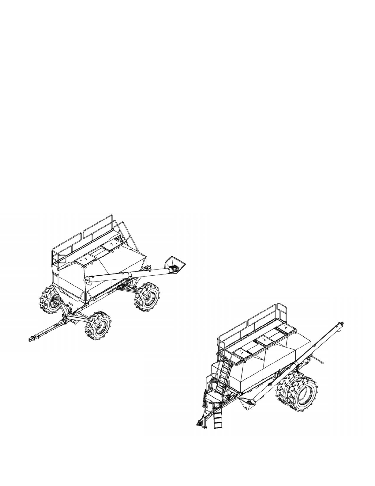
2.3 Air cart
The tanks on the air cart are made of stainless steel to prevent corrosion damage from granular fertilizer.
There are two basic models available that each have two size options:
• Two-bin model - 280 and 335 bushels
• Three-bin model - 380 and 525 bushels
Page 44

2. Introduction
43
2.4 Major components
Fig. 4
The major components for the 3-bin model are shown. The major components for the 2-bin model are in
similar locations.
(1) Front hitch
(2) Ladder
(3) Railer
(4) Auger
(5) Product bin lid
(6) Product bin
(7) Rear hitch
Page 45

Manual holder location
44
For the two-bin model, the manual holder (1) is
located as shown.
For the three-bin model, the manual holder (1) is
located as shown.
2. Introduction
Fig. 5
Fig. 6
Page 46

2. Introduction
45
2.5 Two-bin operator manual
2.5.1 Operator manual storage
The Operator Manual is located in the container (1)
on the machine.
Fig. 7
Page 47

2.6 Three-bin operator manual
46
2.6.1 Operator manual storage
The Operator Manual is located in the container (1)
on the machine.
2. Introduction
Fig. 8
Page 48

2. Introduction
47
Page 49

Table of contents
48
3. Operation
3.1 Ladder and railings ......................................................51
3.1.1 Ladder and railings - two-bin model .........................................51
3.1.2 Ladder and railings - three-bin model ........................................51
3.2 Product bin lids ..........................................................52
3.3 Auger ...................................................................53
3.3.1 Using the auger to load products ..........................................53
3.3.2 Using the auger to unload products .........................................55
3.3.3 Cleaning out the auger ..................................................55
3.4 Ground drive ............................................................56
3.5 Hydraulic systems .......................................................57
3.5.1 Air cart to drill hydraulic coupler ...........................................57
3.5.2 Air cart to tractor hydraulic couplers ........................................57
3.6 Hydraulic drive ..........................................................59
3.7 Blower ..................................................................60
3.7.1 Blower speed ........................................................60
3.8 Selecting air stream .....................................................61
3.9 Meters ..................................................................62
3.9.1 Product meter adjustment ...............................................62
3.9.2 Changing metering rolls - ground drive system ................................63
3.9.3 Changing metering rolls - hydraulic system ...................................63
3.9.4 Meter roll options ......................................................64
3.9.5 Meter adjustments .....................................................64
3.9.5.1 Shims ........................................................64
3.9.5.2 Deflector block .................................................64
3.9.5.3 Meter door and cleanout door latches ................................65
3.9.5.4 Meter door tray .................................................65
3.10 Setting the application rate on a ground drive system ....................66
3.11 Hydraulic drive calibration and operation ................................68
3.11.1 Preparing to calibrate a meter ............................................68
3.11.2 Priming the meter ....................................................69
3.11.3 Taking a product sample for calibration .....................................70
3.11.4 Entering accumulated weight on the virtual terminal ...........................70
3.11.5 Manually setting the motor cal value for a variable rate system ....................71
3.12 Rate charts .............................................................72
3.12.1 Fertilizer rate chart - 96 kg per cubic meter (60 lb per cubic foot) ...................72
3.12.2 Barley rate chart ......................................................74
3.12.3 Canola rate chart .....................................................76
3.12.4 Soybean rate chart ....................................................78
3.12.5 Wheat rate chart .....................................................80
3.13 Raven system ............................................................. 82
3.13.1 Raven system overview .................................................. 82
3.13.2 Raven system hardware .................................................. 82
3.13.2.1 Raven electronic control unit ......................................... 82
3.13.2.2 Virtual terminal ................................................82
3.13.2.3 Blower speed sensor ............................................82
3.13.2.4 Bin level sensor ................................................83
3.13.2.5 Meter box flow sensor ...........................................83
3.13.2.6 Meter shaft speed sensor (ground drive) ..............................83
3.13.2.7 Meter shaft speed sensor (hydraulic drive) ............................84
Page 50

Table of contents
49
3.13.2.8 Ground speed sensor ...........................................84
3.14 Cart control system .....................................................85
3.14.1 Virtual terminal - cart control system .......................................85
3.14.2 Alarm and indicator icons ...............................................85
3.14.3 Confirmation screen ...................................................86
3.14.4 Main (home) screen ...................................................87
3.14.5 Product bin alarms ....................................................89
3.15 System set up ..........................................................90
3.15.1 System settings screen ................................................90
3.15.2 Work switch operation .................................................91
3.15.3 Selecting the external work switch operation mode ............................92
3.15.4 Manual work switch operation ...........................................92
3.15.5 Setting the automatic work switch operation .................................92
3.15.6 Dry product/bin settings ................................................92
3.16 Advanced setup ........................................................94
3.17 Sensor types ...........................................................96
Page 51

3.1 Ladder and railings
50
3.1.1 Ladder and railings - two-bin model
The air cart is equipped with a ladder and railings
for access to the top of the tanks. Always make
sure the railings are fastened in the raised position
when operating the air system. The railings can be
lowered for storage or servicing, if required.
To lower the railings:
1. Use a ladder that is of the correct height, when
put on the ground to reach the top of the
machine, to remove the top bolt from each of
the legs on the railing sections.
2. Rotate the railing section down so that the
railing sections are next to the air system.
3. Install the bolts in the holes for storage.
WARNING:
Falling hazard. Personal injury or
death can occur. Do not stand on the
top of the machine when raising or
lowering the railings. Read and follow
the instructions in the operator's
manual for the movement of the
railings.
3. Operation
Fig. 1
3.1.2 Ladder and railings - three-bin model
The air cart is equipped with a ladder and railings
for access to the top of the tanks. Always make
sure the railings are fastened in the raised position
when operating the air cart. The railings can be
lowered for storage or servicing, if required.
To lower the railings:
1. Use a ladder that is of the correct height, when
put on the ground to reach the top of the
machine, to remove the spring pins.
2. Fold down the side railings over the top of the
tank.
3. Fold down the front and rear hand rails over the
side rails.
4. Install the spring pins for storage.
WARNING:
Falling hazard. Personal injury or
death can occur. Do not stand on the
top of the machine when raising or
lowering the railings. Read and follow
the instructions in the operator's
manual for the movement of the
railings.
Fig. 2
Page 52

3. Operation
51
3.2 Product bin lids
The product bin lids on the air cart compartments
must be correctly closed and sealed for the meters
to supply product correctly.
Periodically check the product bin lids for correct
adjustment and inspect the seal for damage.
To determine whether the product bin lid is
adjusted correctly, watch the product bin lid as the
latch is opened. The product bin lid must tilt a little
toward the latch end. A pull on the latch handle is
required to over-center the latch.
To adjust the hinge end of the product bin lid,
loosen or tighten the jam nuts (1) on the hold
down bar.
To adjust the latch, loosen or tighten the nuts (2)
on the toggle U-bolt.
In the off season, release the latch to relieve
pressure on the gasket.
Fig. 3
Page 53

3.3 Auger
52
The air cart is equipped with an auger (1) for
loading and unloading the product bins. The auger
is mounted in a swing arm. A flexible discharge
hose is mounted on one end. This hose can be
moved from one compartment to another without
moving the hopper. The swing arm also enables
the auger to be turned around to unload and clean
out the compartments.
The hydraulic drive for the auger is supplied with
oil from the blower hydraulics. A diverter valve in
rear of the machine supplies oil to the auger. The
diverter valve can be switched with the blower
running. The diverter valve at the rear of the
machine selects either the fan or auxiliary (auger
and/or winch) function. Push the knob in to run the
blower. Pull the knob out to run the auger or
winch.
The auger has a three position variable speed valve
to run the auger forward, rearward, or to stop.
3. Operation
Fig. 4
3.3.1 Using the auger to load products
Procedure
Park the machine on a solid, level surface.
1.
Apply the park brake.
2.
For the two-bin models, put the auger on the
3.
ground to correctly load the material:
a) Drop the front bracket lock pin (1) just far
enough to release the small pivot arm (2).
Do not remove the pins for the long arm.
b) On the inner arm and the outer arm, pull
down the spring loaded pin into the
detent position.
c) Remove the auger from the rear clamp
assembly.
For the three-bin models only, put the auger
4.
in the operating position:
Fig. 5
Fig. 6
Page 54

3. Operation
53
a) Drop the lock pin (6) in the neutral
position.
b) On the inner arm and the outer arm, pull
down the spring loaded pin into the
detent position.
c) Remove the auger from the clamp.
d) Pull the inner arm into position, by
swinging the hopper away from the air
cart.
e) Release the detent pin on the inner arm
and lock into place.
f) Pull down the outer arm pin so the auger
is free to move from the inner arm.
Put the hopper on the ground:
5.
° For two-bin models, put the hopper in a
position vertical to the center line of the
tanks with the discharge end of the auger
between the compartment covers. From
this position the discharge end of the
auger can move between compartments
without moving the hopper.
° For three-bin models, put the hopper on
the ground in a position perpendicular to
the center tank lid. From this position the
discharge end of the auger can be moved
between compartments without moving
the hopper.
Put the auger over the lid of the desired tank
6.
to be filled.
Push the divert valve knob in to run the
7.
blower. Pull the diverter valve out to run the
auger or winch.
On three-bin models, put the spring loaded
8.
pin into the detent position before moving to
a different compartment or damage can
occur.
Page 55

3.3.2 Using the auger to unload products
54
Procedure
Swing the inner arm far enough away from the machine to let the hopper fit in front of the wheels.
1.
See the information for inner arm position.
Put the hopper (1) under the meter for the
2.
desired compartment.
For rear tank on three-bin models, the outer
arm will have to swing more than 180
degrees to reach the meter.
Close the metering slide (2).
3.
Remove the product meter door (3).
4.
Open the metering slide to control flow from
5.
the compartment.
Removing the pointer lets the gate open
without changing the rate setting.
Fig. 7
3.3.3 Cleaning out the auger
3. Operation
Procedure
Park the machine on a solid, level surface.
1.
Apply the park brake, stop the engine, and take the key with you.
2.
If desired, put a catch pan under the auger.
3.
Put the hopper (1) upside down to empty.
4.
If desired, put a catch pan under the auger.
5.
Run the auger rearward until the auger tube
6.
is empty.
Fig. 8
Page 56

3. Operation
55
3.4 Ground drive
On air carts equipped with ground drive a
magnetic clutch disengages the drive. The
magnetic clutch uses electrical power to hold the
engaged position. The clutch is turned on and off
by the control system either automatically when
the drill is raised and lowered, or manually by
pressing a manual master work switch on the
virtual terminal in the tractor cab. The clutch
requires no service.
When roading long distances, remove the drive
chain at the drive wheel. This will extend the life of
the chain and the sprocket.
Fig. 9
Page 57

3.5 Hydraulic systems
56
3. Operation
The hydraulic system on the air carts includes:
• Blower control circuit
• Auger control circuit
• Hydraulic meter drive control circuit
A group of control valves enables all three circuits
to be operated by one hydraulic remote on the
tractor. This system was designed to function
under a maximum hydraulic pressure of 19 995
kPa (2900 psi).
Fan with
hydraulic
drive
Fan speed Flow Pressure
3000 rpm 49.2 l/min (13
4000 rpm 60.6 l/min (16
5000 rpm 70 l/min (18.5
6000 rpm 79.5 l/min (21
Fan only 10cc fan motor
Fan speed Flow Pressure
10cc fan motor with 5 gal
meter priority
8174 to 11 721
gal/min)
gal/min)
gal/min)
gal/min)
kPa (1200 to
1700 psi)
11 032 to 4
479 kPa (1600
to 2100 psi)
13 790 to 17
237 kPa (2000
to 2500 psi)
16 547 to19
995 kPa (2400
to 2900 psi)
3000 rpm 30.3 l/min (8
gal/min)
4000 rpm 39.7 l/min (10.5
gal/min)
5000 rpm 51 l/min (13.5
gal/min)
6000 rpm 60.6 l/min (16
gal/min)
6895 to 10 342
kPa (1000 to
1500 psi)
9653 to 13 100
kPa (1400 to
1900 psi)
12 411 to 15
858 kPa (1800
to 2300 psi)
15 168 to 18
616 kPa (2200
to 2700 psi)
3.5.1 Air cart to drill hydraulic coupler
The couplers connecting the air cart to the drill/implement are (3/4 inch) #12 ISO 7241 Series B, high-flow
couplers. Using the high-flow couplers reduces the pressure drop across the coupler and enables the
operator to easily disconnect the air cart from the drill/implement. Make sure the pressure line on the tank
is connected to the pressure line on the drill.
The blower motor case drain line has a (5/8 inch) #10 ISO 7241 Series B coupler. The smaller size helps to
tell the difference between this coupler and other larger couplers.
IMPORTANT:
Be sure that the case drain line on the blower motor is not connected to pressure. Damage to the shaft
seal or motor will result.
3.5.2 Air cart to tractor hydraulic couplers
The couplers connecting the blower pressure and the return lines from the air cart to the tractor are #8 (1/2 inch)
ISO 5675 (Pioneer) tip coupler to a #10 (5/8 inch) female ORB.
Page 58

3. Operation
57
A #8 ISO 16028 (at-face) coupler tip to a #6 (3/8 inch) female ORB on the air cart connects the case drain line to the tractor.
The case drain line must be connected or the blower motor will be damaged. If a case drain return port is
not available on your tractor, contact your dealer.
A (3/4 inch) #12 ISO 7241-1 Series A low-pressure return tip is included with all implements. The lowpressure return tip is also available through Service Parts.
If your tractor has a low-pressure port available, the low-pressure return tip can be used on the 3/4 inch
blower return line. Using the low-pressure return tip can remove the pressure drop caused by the 1/2 inch
Pioneer tip and the hydraulic valve of the tractor on the return side. The low-pressure return tip can also be
used on the case drain line, if the 3/8 inch at face port is not available.
Do not install a tee tting connecting the blower return line and the blower case drain lines together. The
blower case line must always be connected to a direct return to the hydraulic reservoir or blower motor
failure will result.
The hydraulic line with the label pressure must be used to operate the blower. A check valve is installed in
the blower circuit to protect the motor from the too much pressure in the return line and prevents
cavitation during shutdown.
NOTE:
The 3/4 inch low pressure return tip is not compatible with the 3/4 inch high ow ttings used at the front
of the cart. The connectors look similar, but the connectors are not compatible.
Page 59

3. Operation
58
3.6 Hydraulic drive
Air systems equipped with the hydraulic drive option use electric-over-hydraulic (EOH) technology to
control the meter speed independently of ground speed. This gives the operator a faster calibration
procedure and on-the-go rate changing capability as well as the option to apply product to a
prescription map using GPS.
The hydraulic control valve uses 18.9 l/min (5 gal/
min) of hydraulic fluid flow from the fan circuit to
power the variable rate drive motors. An electroproportional flow-control valve controls the speed
of each motor, letting the meters turn at speeds
completely independent of each other.
Fig. 10
Page 60

3. Operation
59
3.7 Blower
The blower system for the air cart generates air
pressure/flow to carry the seed or other input
products through the system to the implement. A
hydraulic motor drives the blower system. Two 3/4
inch hydraulic lines supply oil to the blower.
The only part on the blower that can be serviced is
the shaft seal. The shaft seal can be replaced if the
motor leaks at the shaft. Do not disassemble the
motor to replace the shaft seal. The shaft seal is
fastened by a snap ring and can be removed with a
seal pick.
IMPORTANT:
Be sure that the case drain line on the blower
motor is not connected to pressure. Damage to
the shaft seal or motor will result.
IMPORTANT:
Do not under any circumstances disassemble the
motor. The motor is very difficult to correctly
assemble and motor destruction will result. If a
motor failure occurs, get a replacement motor
from the dealer.
Fig. 11
3.7.1 Blower speed
Operate the blower at as slow a speed as possible to prevent damage to seed. If operated too slowly, line
blockage will occur. Typical blower speeds are between 3000 and 6000 rpm. The drill width, product, rate,
humidity, and other factors can change blower speed.
If a run blockage monitor is not used, make sure all runs are operating after changing blower speeds. To
check the runs:
1. Turn the meter(s) with the blower running
2. Make sure there is product at each ground opener
If high rates are being applied with this implement and the implement is equipped with two fans, use the
fan only circuit with the low pressure return fitting. This will help decrease the back pressure in the circuit
and give the maximum output.
The number of outlets on the implement will directly change the blower rpm. The more outlets in use, the
higher the pressure required to keep blower rpm. See your dealer for hydraulic adjustments to your tractor,
if necessary.
A diverter valve in front of the cart selects the fan or auxiliary function. Push the knob in to run the blower.
Pull the knob out to run the auger or winch.
One method to determine blower RPM is to remove a final run from the seed boot or shoe. Hold the hose
about 1.5 meter (5 ft) off of the ground pointing straight up. Turn product out of the meter with the blower
running. The product coming from the hose must blow out of the hose approximately 203 mm (8 inches)
into the air. Adjust blower RPM as required.
Page 61

3.8 Selecting air stream
60
In dual chute equipped systems; one can switch air streams for any desired products.
Procedure
Remove the wing nuts (1) from the baffle
1.
slide and the plug.
Remove the baffle slide.
2.
Move the baffle slide into the desired air
3.
stream.
Install the plug and the wing nuts.
4.
Do not use wrench to tighten the wing nuts.
Over tightening will cause failure of the stud.
Move the pressurization tube to the desired
5.
air stream.
If changing air streams frequently, apply a
small amounts of an anti-seize compound to
the studs. This will keep the studs from
seizing and becoming broken.
Fig. 12
3. Operation
Page 62

3. Operation
61
3.9 Meters
3.9.1 Product meter adjustment
The product meters send the seed or fertilizer
from the product bins to the air stream through a
fluted roller. The amount of the roller being used
determines the rate at which products are applied.
There are two moveable components in the meter
that determine the rate setting:
• Flow plate
• Meter shut off slide
The flow plate (1) controls how much of the meter
roller will be used. The meter shut off slide (2)
opens to the stop on the pointer for any rate
setting. When making large rate reductions, close
the slide and empty the meter to let the flow plate
move to the lower setting. After the flow plate is
moved, open the meter shut off slide until contact
is made with the stop on the pointer.
The primary setting is a flow plate adjusted by a
rod connected to a pointer. When a rate setting is
selected, the pointer is put at the number shown
on the rate decal. A lock bolt on the pointer rod
holds the setting.
Fig. 13
The second part of the adjustment is the meter
shut off slide. For any rate setting the correct
location for meter shut off slide is against the stop
on the pointer. This opens the bottom of the tank
compartment the correct amount for the rate
setting. A 12.5 mm (0.5 inch) drive ratchet is
supplied in the toolbox for adjusting the meter
shut off slide.
Any time a new rate is set, calibrate the meter. A
scale and a catch bag are supplied in the tool box
for use during the calibration procedure.
Once a rate setting is determined from the rate
charts and the meter is set to the correct setting,
do the calibration procedures.
When using both tanks for one product, determine
the rate for each meter by splitting the desired rate
by the ratio of the tanks (60/40). This will result in
both tanks being empty at the same time.
Examples:
To seed 135 kg per hectare of wheat using both
meters, split the desired rate to the ratio of the
size of the tanks. For a 60/40 split, set one meter
to 81 kg (135 kg x .60) and the other meter to 54
kg (135 kg x .40)
To seed 120 lbs per acre of wheat using both
meters, split the desired rate to the ratio of the
size of the tanks. For a 60/40 split, set one meter
Page 63

to 72 lbs (120 lbs x .60) and the other meter to 48
62
lbs (120 lbs x .40).
When decreasing the meter setting, close the
shutoff slide and turn the meter, if necessary. This
procedure will empty the meter and let the plate
move to a smaller setting.
3.9.2 Changing metering rolls - ground drive system
Procedure
Close the meter gate or make sure the bin is empty.
1.
Remove the meter door.
2.
Remove the chain (1) from the meter drive
3.
sprocket.
Do not remove the sprocket.
On the sprocket end of the meter drive only,
4.
remove the two nuts (2) that hold the bearing
to the meter shaft.
Pull the shaft (3) out of the meter drive while
5.
holding on the the metering roll (4).
Remove the metering roll.
6.
Install the desired metering roll.
7.
Install the shaft into the meter drive through
8.
the metering roll.
Install the two nuts that hold the bearing to
9.
the meter shaft.
Install the chain to the meter drive sprocket.
10.
Install the meter door.
11.
Fig. 14
3. Operation
3.9.3 Changing metering rolls - hydraulic system
Procedure
Close the meter gate or make sure the bin is empty.
1.
Remove the meter door.
2.
Remove the two 1/2 inch bolts (1) fastening
3.
the hydraulic motor to the motor mount.
On the motor end of the meter drive only,
4.
remove the two nuts (2) that hold the bearing
to the meter shaft.
Pull the shaft (3) connected to the hydraulic
5.
motor out of the meter drive while holding
on the the metering roll (4).
Remove the metering roll.
6.
Install the desired metering roll.
7.
Install the shaft connected to the hydraulic
8.
motor into the meter drive through the
metering roll.
Install the two nuts that hold the bearing to
9.
the meter shaft.
Install the two 1/2 inch bolts fastening the
10.
hydraulic motor to the motor mount.
Fig. 15
Page 64

3. Operation
63
Install the meter door.
11.
3.9.4 Meter roll options
Four meter roll options are available:
• The high capacity roll has eight 12.7 mm (1/2 in) deep bars and is used for most applications.
• The medium capacity roll has 12 6.4 mm (1/4 in) deep bars and is used on smaller machines or for
lower seeding or fertilizer rates.
• The low volume roll has a pattern of short, shallow depressions to gradually longer, deeper depressions
for very low seeding rate.
• The fine product meter roll has a continuous pattern of shallow depressions for very low seeding rates
with high accuracy.
3.9.5 Meter adjustments
The following adjustments are done at the factory and done only be done by a trained service technician.
3.9.5.1 Shims
The meter roll has a 0.762 mm (0.030 in) gap
between the roll and the meter housing for correct
operation. If the gap is too large product can leak
around the meter roll into the air stream. If the gap
is too tight the meter roll will not move on the
housing and cause problems with the meter drive
system.
A 0.762 mm (0.030 in) thick shim can be installed
between the meter roll and the meter housing to
reduce this gap. The meter shaft must be removed
to install this shim. See the information for
changing meter rolls.
Make sure the meter roll turns freely after
installing or removing any shims. If the meter roll
does not turn freely, do not operate the air system
until enough shims have been removed to let the
meter roll turn freely.
3.9.5.2 Deflector block
The deflector block (1) at the rear of the meter
prevents seed from flowing around the back side
of the meter roll. If necessary, vertically adjust the
deflector block to increase or decrease the
clearance to the meter roll.
To adjust the deflector block:
1. Loosen the two nuts (2) on the back side of the
meter housing.
2. Move the deflector block to the desired
position.
3. Tighten the two nuts on the back side of the
meter housing.
Fig. 16
Fig. 17
Page 65

3.9.5.3 Meter door and cleanout door latches
64
The tension on the cleanout door latches (1) and
the meter door latches (2) can be adjusted to
increase or decrease the preload on the cleanout
door and the meter door. If the preload is too
small, the doors will not seal correctly. If the
tension is too tight, the latches will be difficult to
close.
The tension can be adjusted by opening each latch
and turning the two stop-nuts evenly in or out.
Make sure the door preload is enough before
putting the unit back into service.
3.9.5.4 Meter door tray
The tray (1) on the meter door can be adjusted
vertically in order to increase or decrease the
tension between the rubber seal on the tray and
the meter roll.
3. Operation
Fig. 18
To adjust the meter door tray:
1. Loosen the two nuts (2) holding the tray to the
meter door.
2. Move the tray to the desired position.
3. Tighten the nuts to lock the tray into position.
Fig. 19
Page 66

3. Operation
65
3.10 Setting the application rate on a ground drive system
Before starting the procedure
See the information for preparing to calibrate a meter. See the information for priming the meter. See the
information for taking a sample for calibration. Close the slide gates for any meter not being calibrated.
The ground drive (GD) system changes meter speed as necessary to keep a constant application rate.
Procedure
Connect the machine hitch to a tractor.
1.
Put the tractor hydraulic remote in the neutral position.
2.
Connect the machine hydraulic lines to the tractor.
3.
Connect the machine terminal harness to the terminal harness.
4.
Start the tractor.
5.
Put the transmission in park and apply the park brake.
6.
Turn on the terminal.
7.
Make sure the terminal and the machine electronic control unit (ECU) connect.
Determine the desired application rate from the ground drive part of the rate charts.
8.
Look up the rate setting for each tank separately. Use the correct rate chart.
Loosen the thumb screw on the pointer shaft so the pointer shaft can move.
9.
Set the pointer to the desired application rate.
10.
Tighten the thumb screw to hold the setting.
11.
Open the slide gate with the supplied ratchet wrench until the slide gate contacts the stop on the
12.
pointer.
Hang the empty calibration bag on the weighing scale included with the machine.
13.
Zero out the weight of the empty calibration bag.
14.
Release the toggle clamps and open the cleanout door under the air tube.
15.
Turn the crank at the front of the air system one complete revolution to prime the meter.
16.
Install the calibration bag on the meter tube with the cleanout door inside the bag.
17.
The bag must be under the openings in the bottom of the air tube.
To calibrate a seeding rate for most seeds, determine the number of crank turns to cover 0.04 ha (0.1
18.
acre).
To calibrate a seeding rate for seeds with a small weight per area, use more crank turns than
19.
required for 0.04 ha or (0.1 acre).
Canola seeds and sunflower seeds require a larger number of crank turns for correct calibration.
To calibrate a seeding rate for seeds with a very small weight of seed per area, use the crank turns
20.
for 0.4 ha (1 acre).
Manually crank the meter the required number of turns.
21.
Machine width, turns of the crank, teeth, and tire sizes
Machine Width in
m or (ft)
9.1 m (30 ft) 467 turns per ha (189 turns per acre) 311 turns per ha (126 turns per acre)
9.8 m (32 ft) 441 turns per ha (179 turns per acre) 294 turns per ha (119 turns per acre)
10.4 m (34 ft) 415 turns per ha (168 turns per acre) 277 turns per ha (112 turns per acre)
11.0 m (36 ft) 393 turns per ha (159 turns per acre) 262 turns per ha (106 turns per acre)
Turns of the crank per ha (acre) with a
10 tooth gearbox sprocket and
23.1R26 tires
Turns of the crank per ha (acre) with a
15 tooth gearbox sprocket and
23.1R26 tires or with a 17 tooth
gearbox sprocket and 18.4R26 tires.
Page 67

Machine width, turns of the crank, teeth, and tire sizes
66
3. Operation
Machine Width in
m or (ft)
Turns of the crank per ha (acre) with a
10 tooth gearbox sprocket and
23.1R26 tires
Turns of the crank per ha (acre) with a
15 tooth gearbox sprocket and
23.1R26 tires or with a 17 tooth
gearbox sprocket and 18.4R26 tires.
11.6 m (38 ft) 371 turns per ha (150 turns per acre) 247 turns per ha (100 turns per acre)
12.2 m (40 ft) 352 turns per ha (143 turns per acre) 235 turns per ha (95 turns per acre)
12.8 m (42 ft) 334 turns per ha (135 turns per acre) 222 turns per ha (90 turns per acre)
13.4 m (44 ft) 319 turns per ha (129 turns per acre) 213 turns per ha (86 turns per acre)
13.7 m (45 ft) 315 turns per ha (128 turns per acre) 210 turns per ha (85 turns per acre)
14.0 m (46 ft) 308 turns per ha (125 turns per acre) 205 turns per ha (83 turns per acre)
14.6 m (48 ft) 293 turns per ha (119 turns per acre) 195 turns per ha (79 turns per acre)
15.2 m (50 ft) 282 turns per ha (114 turns per acre) 188 turns per ha (76 turns per acre)
15.8 m (52 ft) 271 turns per ha (110 turns per acre) 180 turns per ha (73 turns per acre)
16.5 m (54 ft) 259 turns per ha (105 turns per acre) 173 turns per ha (70 turns per acre)
17.1 m (56 ft) 252 turns per ha (102 turns per acre) 168 turns per ha (68 turns per acre)
17.7 m (58 ft) 245 turns per ha (99 turns per acre) 163 turns per ha (66 turns per acre)
18.3 m (60 ft) 234 turns per ha (95 turns per acre) 63 turns per ha (63 turns per acre)
Remove the calibration bag.
22.
Weigh the calibration bag.
23.
For most seeds, multiply the sample weight times ten to get the rate per 0.4 ha (1.0 acre).
24.
For seeds with a small weight per area multiply the sample weight by the inverse of the sample
25.
percent.
Examples: For a 50 percent sample size, (1.0/0.5 = 2) multiply by two; for a 40 percent sample size,
(1.0/0.4 = 2.5) multiply by 2.5.
For seeds with a very small weight per area, use the sample weight.
26.
Repeat the procedure if necessary, adjusting the meter to a higher or lower setting to get the desired
27.
rate.
After finishing the procedure
Recalibrate rates after seeding with a partial tank of seeds.
Page 68

3. Operation
67
3.11 Hydraulic drive calibration and operation
3.11.1 Preparing to calibrate a meter
Calibrate meter when:
• Changing the gate setting
• Changing the product
• Changing the meter roll
Calibrate each meter even if all gates have the same setting.
Procedure
Connect the machine hitch to a tractor.
1.
Put the tractor hydraulic remote in the neutral position.
2.
Connect the machine hydraulic lines to the tractor.
3.
Connect the machine terminal harness to the terminal harness.
4.
Start the tractor.
5.
Put the transmission in park and apply the park brake.
6.
Turn on the terminal.
7.
Make sure the terminal and the machine electronic control unit (ECU) connect.
Check the meter gate for correct connection to the meter roll.
8.
If necessary, make corrections.
Check the bin for product.
9.
The bin must be a minimum of 25 percent
full.
Adjust the meter gate (1) for the correct
10.
application rate.
The measuring rule (2) shows inches and
parts of an inch.
Use the following table to set the meter gate.
11.
Meter gate setting guide for hydraulic drives with high capacity meter rolls
Rate in kg/ha (lbs/
acre)
56 kg/ha (50 lb/
acre)
112 kg/ha (100 lb/
acre)
168 kg/ha (150 lb/
acre)
224 kg/ha (200 lb/
acre)
9 m (30 ft) 12 m (40 ft) 15 m (50 ft) 18 m (60 ft)
76 mm (3 in)
.5 lbs/rev
102 mm (4 in)
.33 lbs/rev
152 mm (6 in)
1.0 lbs/rev
203 mm (8 in)
1.33 lbs/rev
Fig. 20
102 mm (4 in)
.66 lbs/rev
152 mm (6 in)
1.0 lbs/rev
203 mm (8 in)
1.33 lbs/rev
254 mm (10 in)
1.66 lbs/rev
127 mm (5 in)
.83 lbs/rev
203 mm (8 in)
1.33 lbs/rev
254 mm (10 in)
1.66 lbs/rev
maximum opening
2.0 lbs/rev
152 mm (6 in)
1.0 lbs/rev
254 mm (10 in)
1.66 lbs/rev
maximum opening
2.0 lbs/rev
maximum opening
2.0 lbs/rev
Page 69

Operate the auger selector valve (1) to send
68
12.
hydraulic oil to the fan/meter circuit.
Close the blower ball-valve.
13.
Engage the tractor hydraulic remote
14.
controlling the blower circuit.
Make sure the blower does not rotate. If the
blower rotates, close the blower ball-valve.
Open the cleanout door below the meter to
15.
be calibrated.
Priming the Meter
The electronic control unit (ECU) has a touch
pad (1) that will be used for calibration.
3. Operation
Fig. 21
Before starting the procedure:
Enter the Rate Sensor Setup Screen (1) found in the
System settings menu.
From the table on previous page enter a Calibration
Rate based metering wheel, width of machine, and
rate desired for each (PR) Product (1).
This calibration value is a starting point at which
you will need to start the calibration procedure.
Fig. 22
If the product density is known, enter it for the
desired product.
Do not Change the Product Density After
Calibrating - The calibration number will change
Be sure that the Master Apply switch is on and
green.
Fig. 23
Page 70

3. Operation
69
Setting Machine Width:
Select Settings and select the Applicator Set up tab.
Verify that your machine width (1) is populated correctly.
If the width is correct move onto the calibration
procedure, if not follow the next steps:
1. Select Edit
a. The ECU will prompt you asking if want to
Remove/Edit (1) a profile from the list, Select
the Check Mark
Fig. 24
2. Select Profile name;
a. Typically this is the Model and Drive type of
the Air cart: ie: 3350HYD
3. Change the Application Width (1) of the machine.
4. Page Through the next screens until you reach the
Set up Summary;
a. Verify all settings are correct and select
next.
Fig. 25
Fig. 27
Page 71

3. Operation
70
3.11.3 Taking a product sample for calibration from the Auxillary Display
Before starting the calibration procedure:
The meter roll must be primed with product before
calibrating the meter.
Procedure:
1. Hang Calibration Bag (1) under meter being
calibrated (Fig. 24)
Fig. 24
2. Enter the Rate Calibration Menu;
a. Use arrow pad to navigate.
b. Press "ok" to enter menu.
3. Select the product using the left and right
arrow keys (1).
a. Note the Current Calibration should
match what was entered into the
terminal in the cab.
4. Select CALIBRATE using the rightmost
button.
5. A Warning screen will appear;
a. PLEASE READ THIS WARNING
b. Press "ok".
Fig. 25
Fig. 26
Fig. 27
Page 72

3. Operation
71
6. Catch Test Summary;
a. Select Edit
b. Enter a Test Speed
i. Highlight the field and press
"ok" to enter a value.
ii. Approximately the speed at
which you will be seeding.
c. Enter Rate at which you will be
applying that product.
i. Highlight the field and press
"ok" to enter value.
d. Enter Desired weight to be
dispense
i. Highlight the field and press
"ok" to enter a value.
ii. Recommended to catch
15-25 lbs of product.
iii. No less than 10lbs.
7. Select Next.
8. Select Prime;
a. The Meter will turn 1 revolution
b. It is suggested to Prime (1) 2-3 times
to ensure the meter is full of
product.
9. Empty Calibration hang back under the
desired meter and begin Calibration.
Fig. 28
Fig. 29
3.11.3 Taking a product sample for calibration
1. Hang Calibration bag under meter being
calibrated
2. Press Start (1).
Fig. 30
3. When Calibration is complete you will be
prompted to enter Actual Amount Applied;
a. Use arrow pad to enter value
measured using scale provided in
the calibration kit.
b. When measuring, be sure to have
zeroed the scale with the bag
weight in account.
c. Be sure the scale is in "lbs".
Fig. 31
Page 73

3. Operation
72
4. Review the Catch Test Results:
a. The results may vary based on initial values.
5. It is suggested that you recalibrate after you
received the results. This allows for the machine
to make the adjustments and obtain a more
accurate calibration number.
6. Press OK
Fig. 32
3.11.3 Taking a product sample for calibration from Field Computer (In Cab)
If the auxiliary display is not available the calibration process can be completed from the In-Cab Field Computer
1. Select the Settings and select System Settings
2. Rate Sensor Set up (1).
3. Enter a Calibration Value based on door opening.
4. If the product density is known, enter it for the
desired product.
Do not Change the Product Density After
Calibrating - The calibration number will
change
5. Select Catch Test Calibration.
6. Select Check Mark (1).
Page 74

3. Operation
73
A warning screen will alarm, read and take note of
the warning statement
7. Calibrate Rate Sensor:
a. Enter Test Speed:
i. Approximately the speed at which
you will be seeding.
b. Enter Rate at which you will be applying
that product.
c. Enter weight to be dispense;
i. Recommended to catch 15/25 lbs
of product.
ii. No Less than 10lbs.
d. Select Next.
8. Hang the bag under the product you wish to
calibrate.
9. If your Master Switch is not on, the Field
Computer will display MASTER OFF (1).
When On, the Start button (1) will appear,
a. Select and the status bar will start to
load.
Page 75

3. Operation
74
10. When complete, the Field Computer will
prompt enter the catch weight:
a. Enter this in lbs - tenths.
b. Be sure the bag weight is removed.
11. Review the Catch Test Results:
a. The results may vary based on initial values.
12. It is suggested that you recalibrate after you
received the results. This allows for the machine
to make the adjustments and obtain a more
accurate calibration number.
13. Press OK.
Page 76

3.11.5 Manually setting the motor cal value for a variable rate system
75
Procedure
1.
Select
Select the Calibration Weight (2).
2.
Enter the desired calibration weight (2).
3.
The calibration weight is the amount of product
applied per revolution on the meter roller. The
calibration weight is calculated using the
accumulated weight value (2) and the
revolutions of the meter. If the motor spins 10
revolutions and accumulates 10 pounds, the
calibration weight value is 1.000.
Do not Change the Product Density After
Calibrating - The calibration number will
change.
(1) for the desired bin:
3. Operation
Page 77

3. Operation
76
3.12 Rate charts
3.12.1 Fertilizer rate chart - 96 kg per cubic meter (60 lb per cubic foot)
Use the high capacity meter roll (1), part number
65705, with 12.27 mm (0.483 in) deep (A) x 16.74
mm (0.659 in) wide (B) flutes (2). The high capacity
meter roll has 6 mm (0.25 in) wide x 13 mm (0.5
in) high bars (3).
Fig. 27
Fig. 28
This table applies to ground drive machines with: 17 tooth gear box sprocket and 18.4R26 tires, or 15 tooth
gear box sprocket and 23.1R26 tires. This table does not apply to other gear box sprocket or tire sizes.
Width m
(ft).
Read
across.
Applicati
on rate
in kg/ha
(lb/acre).
Read
down.
67 kg/ha
(60 lb/
acre)
78 kg/ha
(70 lb/
acre)
6.1m (20
ft)
Approxi
mate
pointer
setting in
inches.
(2.3 in) (2.9 in) (3.5 in) (4.0 in) (4.6 in) (5.2 in) (5.8 in) (6.3 in) (6.9 in)
(2.7 in) (3.4 in) (4.0 in) (4.7 in) (5.4 in) (6.0 in) (6.7 in) (7.4 in) (8.1 in)
7.6m (25
ft)
9.1m (30
ft)
10.7m
(35 ft)
12.2m
(40 ft)
13.7m
(45 ft)
15.2m
(50 ft)
16.8m
(55 ft)
18.3m
(60 ft)
Page 78

3. Operation
77
90 kg/ha
(80 lb/
acre)
101 kg/
ha (90 lb/
acre)
112 kg/
ha (100
lb/acre)
123 kg/
ha (110
lb/acre)
135 kg/
ha (120
lb/acre)
146 kg/
ha (130
lb/acre)
157 kg/
ha (140
lb/acre)
(3.1 in (3.8 in) (4.6 in) (5.4 in) (6.1 in) (6.9 in) (7.7 in) (8.4 in) (9.2 in)
(3.5 in) (4.3 in) (5.2 in) (6.0 in) (6.9 in) (7.8 in) (8.6 in) (9.5 in) (10.4 in)
(3.8 in) (4.8 in) (5.8 in) (6.7 in) (7.7 in) (8.6 in) (9.6 in) (10.6 in) (11.5 in)
(4.2 in) (5.3 in) (6.3 in) (7.4 in) (8.4 in) (9.5 in) (10.6 in) (11.6 in) (12.7 in)
(4.6 in) (5.8 in) (6.9 in) (8.1 in) (9.2 in) (10.4 in) (11.5 in) (12.7 in) (13.8 in)
(5.0 in) (6.2 in) (7.5 in) (8.7 in) (10.0 in) (11.2 in) (12.5 in) (13.7 in)
(5.4 in) (6.7 in) (8.1 in) (9.4 in) (10.8 in) (12.1 in) (13.4 in)
168 kg/
ha (150
lb/acre)
179 kg/
ha (160
lb/acre)
191 kg/
ha (170
lb/acre)
202 kg/
ha (180
lb/acre)
213 kg/
ha (190
lb/acre)
224 kg/
ha (200
lb/acre)
235 kg/
ha (210
lb/acre)
(5.8 in) (7.2 in) (8.6 in) (10.1 in) (11.5 in) (13.0 in)
(6.1 in) (7.7 in) (9.2 in) (10.8 in) (12.3 in) (13.8 in)
(6.5 in) (8.2 in) (9.8 in) (11.4 in) (13.1 in)
(6.9 in) (8.6 in) (10.4 in) (12.1 in) (13.8 in)
(7.3 in) (9.1 in) (10.9 in) (12.8 in)
(7.7 in) (9.6 in) (11.5 in) (13.4 in)
(8.1 in) (10.1 in) (12.1 in)
Page 79

3. Operation
78
247 kg/
(8.4 in) (10.6 in) (12.7 in)
ha (220
lb/acre)
258 kg/
(8.8 in) (11.0 in) (13.2 in)
ha (230
lb/acre)
269 kg/
(9.2 in) (11.5 in) (13.8 in)
ha (240
lb/acre)
3.12.2 Barley rate chart
Use the high capacity meter roll (1), part number
65705, with 12.27 mm (0.483 in) deep (A) x 16.74
mm (0.659 in) wide (B) flutes (2). The high capacity
meter roll has 6 mm (0.25 in) wide x 13 mm (0.5
in) high bars (3).
Fig. 29
Fig. 30
This table applies to ground drive machines with: 17 tooth gear box sprocket and 18.4R26 tires, or 15 tooth
gear box sprocket and 23.1R26 tires. This table does not apply to other gear box sprocket or tire sizes.
Page 80

3. Operation
79
Width m
(ft).
Read
across.
Applicati
on rate
in kg/ha
(lb/acre).
Read
down.
67 kg/ha
(60 lb/
acre)
78 kg/ha
(70 lb/
acre)
90 kg/ha
(80 lb/
acre)
101 kg/
ha (90 lb/
acre)
6.1m (20
ft)
7.6m (25
ft)
9.1m (30
ft)
10.7m
(35 ft)
12.2m
(40 ft)
13.7m
(45 ft)
15.2m
(50 ft)
16.8m
(55 ft)
18.3m
(60 ft)
Approxi
mate
pointer
setting in
inches.
(3.4 in) (4.2 in) (5.0 in) (5.9 in) (6.7 in) (7.5 in) (8.4 in) (9.2 in) (10.1 in)
(3.9 in) (4.9 in) (5.8 in) (6.8 in) (7.8 in) (8.8 in) (9.8 in) (10.7 in) (11.7 in)
(4.5 in (5.6 in) (6.7 in) (7.8 in) (8.9 in) (10.0 in) (11.1 in) (12.2 in) (13.4 in)
(5.0 in) (6.3 in) (7.6 in) (8.8 in) (10.1 in) (11.4 in) (12.6 in) (13.9 in)
112 kg/
ha (100
lb/acre)
123 kg/
ha (110
lb/acre)
135 kg/
ha (120
lb/acre)
146 kg/
ha (130
lb/acre)
157 kg/
ha (140
lb/acre)
168 kg/
ha (150
lb/acre)
179 kg/
ha (160
lb/acre)
(5.6 in) (7.0 in) (8.4 in) (9.8 in) (11.2 in) (12.6 in) (14.0 in)
(6.2 in) (7.7 in) (9.2 in) (10.8 in) (12.3 in) (13.8 in)
(6.7 in) (8.4 in) (10.1 in) (11.7 in) (13.4 in)
(7.3 in) (9.1 in) (10.9 in) (12.8 in)
(7.8 in) (9.8 in) (11.8 in) (13.7 in)
(8.4 in) (10.5 in) (12.6 in)
(8.9 in) (11.2 in) (13.4 in)
191 kg/
ha (170
lb/acre)
202 kg/
ha (180
lb/acre)
(9.5 in) (11.9 in)
(10.1 in) (12.6 in)
Page 81

3. Operation
80
213 kg/
(10.7 in) (13.3 in)
ha (190
lb/acre)
224 kg/
(11.2 in)
ha (200
lb/acre)
235 kg/
(11.8 in)
ha (210
lb/acre)
247 kg/
(12.3 in)
ha (220
lb/acre)
258 kg/
(12.9 in)
ha (230
lb/acre)
269 kg/
(13.4 in)
ha (240
lb/acre)
3.12.3 Canola rate chart
Use the fine product meter roll (1), part number
67639, with 3 mm (0.125 in) deep (A) x 13 mm
(0.5 in) wide (B) x 25.4 mm (1 in) long (C) slots (2).
The slots have a 38.1 mm (1.5 in) offset from slot
to slot within rows.
The slots have an 8 mm (0.313 in) curve (D).
Fig. 31
Fig. 32
This table applies to ground drive machines with: 17 tooth gear box sprocket and 18.4R26 tires, or 15 tooth
gear box sprocket and 23.1R26 tires. This table does not apply to other gear box sprocket or tire sizes.
Page 82

3. Operation
81
Width m
(ft).
Read
across.
Applicati
on rate
in kg/ha
(lb/acre).
Read
down.
1.36 kg/
ha (3 lb/
acre)
1.81 kg/
ha (4 lb/
acre)
2.27 kg/
ha (5 lb/
acre)
2.72 kg/
ha (6 lb/
acre)
6.1m (20
ft)
Approxi
mate
pointer
setting in
inches.
7.6m (25
ft)
9.1m (30
ft)
10.7m
(35 ft)
12.2m
(40 ft)
13.7m
(45 ft)
15.2m
(50 ft)
16.8m
(55 ft)
18.3m
(60 ft)
(0.4 in) (0.9 in) (1.4 in)
(0.8 in) (1.4 in) (2.1 in) (2.8 in) (3.5 in)
(0.4 in) (1.3 in) (2.1 in) (3.0 in) (3.9 in) (4.7 in) (5.6 in)
(0.4 in) (1.4 in) (2.5 in) (3.5 in) (4.5 in) (5.6 in) (6.6 in) (7.6 in)
3.18 kg/
ha (7 lb/
acre)
3.63 kg/
ha (8 lb/
acre)
4.08 kg/
ha (9 lb/
acre)
4.54 kg/
ha (10 lb/
acre)
4.99 kg/
ha (11 lb/
acre)
5.44 kg/
ha (12 lb/
acre)
5.90 kg/
ha (13 lb/
acre)
(1.3 in) (2.5 in) (3.7 in) (4.9 in) (6.1 in) (7.3 in) (8.5 in) (9.7 in)
(0.8 in) (2.1 in) (3.5 in) (4.9 in) (6.3 in) (7.6 in) (9.0 in) (10.4 in) (11.8 in)
(1.4 in) (3.0 in) (4.5 in) (6.2 in) (7.6 in) (9.2 in) (10.7 in) (12.3 in)
(2.1 in) (3.9 in) (5.6 in) (7.3 in) (9.0 in) (10.7 in) (12.5 in)
(2.8 in) (4.7 in) (6.6 in) (8.5 in) (10.4 in) (12.3 in)
(3.5 in) (5.6 in) (7.6 in) (9.7 in) (11.8 in)
(4.2 in) (6.4 in) (8.7 in) (10.9 in) (13.1 in)
6.35 kg/
ha (14 lb/
acre)
6.80 kg/
ha (15 lb/
acre)
(4.9 in) (7.3 in) (9.7 in) (12.1 in)
(5.6 in) (8.2 in) (10.7 in) (13.3 in)
Page 83

3. Operation
82
3.12.4 Soybean rate chart
Use the high capacity meter roll (1), part number
65705, with 12.27 mm (0.483 in) deep (A) x 16.74
mm (0.659 in) wide (B) flutes (2). The high capacity
meter roll has 6 mm (0.25 in) wide x 13 mm (0.5
in) high bars (3).
Fig. 33
Fig. 34
This table applies to ground drive machines with: 17 tooth gear box sprocket and 18.4R26 tires, or 15 tooth
gear box sprocket and 23.1R26 tires. This table does not apply to other gear box sprocket or tire sizes.
Width m
(ft).
6.1m (20
ft)
7.6m (25
ft)
9.1m (30
ft)
10.7m
(35 ft)
12.2m
(40 ft)
13.7m
(45 ft)
15.2m
(50 ft)
16.8m
(55 ft)
18.3m
(60 ft)
Read
across.
Applicati
on rate
in kg/ha
(lb/acre).
Read
Approxi
mate
pointer
setting in
inches.
down.
67 kg/ha
(3.1 in) (3.9 in) (4.7 in) (5.4 in) (6.2 in) (7.0 in) (7.8 in) (8.5 in) (9.3 in)
(60 lb/
acre)
78 kg/ha
(3.6 in) (4.5 in) (5.4 in) (6.3 in) (7.2 in) (8.1 in) (9.1 in) 10.0 in) 10.9 in)
(70 lb/
acre)
90 kg/ha
(4.1 in) (5.2 in) (6.2 in) (7.2 in) (8.3 in) (9.3 in) 10.3 in) (11.4 in) (12.4 in)
(80 lb/
acre)
Page 84

3. Operation
83
101 kg/
ha (90 lb/
acre)
112 kg/
ha (100
lb/acre)
123 kg/
ha (110
lb/acre)
135 kg/
ha (120
lb/acre)
146 kg/
ha (130
lb/acre)
157 kg/
ha (140
lb/acre)
168 kg/
ha (150
lb/acre)
(4.6 in) (5.8 in) (6.9 in) (8.0 in) (9.2 in) 10.4 in) (11.5 in) (12.6 in) (13.8 in)
(5.2 in) (6.4 in) (7.7 in) (9.0 in) 10.3 in) (11.6 in) (12.9 in) (14.2 in)
(5.7 in) (7.1 in) (8.6 in) 10.0 in) (11.4 in) (12.8 in) (14.0 in)
(6.2 in) (7.8 in) (9.3 in) 10.9 in) (12.4 in) (14.0 in)
(6.7 in) (8.4 in) 10.1 in) (11.7 in) (13.4 in)
(7.2 in) (9.0 in) 10.8 in) (12.6 in)
(7.7 in) (9.6 in) (11.6 in) (13.5 in)
179 kg/
ha (160
lb/acre)
191 kg/
ha (170
lb/acre)
202 kg/
ha (180
lb/acre)
213 kg/
ha (190
lb/acre)
224 kg/
ha (200
lb/acre)
235 kg/
ha (210
lb/acre)
247 kg/
ha (220
lb/acre)
(8.2 in) 10.3 in) (12.3 in)
(8.8 in) 10.9 in) (13.1 in)
(9.3 in) (11.6 in) (13.9 in)
(9.8 in) (12.2 in)
10.4 in) (12.9 in)
10.9 in) (13.6 in)
(11.4 in)
258 kg/
ha (230
lb/acre)
269 kg/
ha (240
lb/acre)
(11.9 in)
(12.4 in)
Page 85

3. Operation
84
3.12.5 Wheat rate chart
Use the high capacity meter roll (1), part number
65705, with 12.27 mm (0.483 in) deep (A) x 16.74
mm (0.659 in) wide (B) flutes (2). The high capacity
meter roll has 6 mm (0.25 in) wide x 13 mm (0.5
in) high bars (3).
Fig. 35
Fig. 36
This table applies to ground drive machines with: 17 tooth gear box sprocket and 18.4R26 tires, or 15 tooth
gear box sprocket and 23.1R26 tires. This table does not apply to other gear box sprocket or tire sizes.
Width m
(ft).
6.1m (20
ft)
7.6m (25
ft)
9.1m (30
ft)
10.7m
(35 ft)
12.2m
(40 ft)
13.7m
(45 ft)
15.2m
(50 ft)
16.8m
(55 ft)
18.3m
(60 ft)
Read
across.
Applicati
on rate
in kg/ha
(lb/acre).
Read
Approxi
mate
pointer
setting in
inches.
down.
67 kg/ha
(2.7 in) (3.4 in) (4.1 in) (4.7 in) (5.4 in) (6.1 in) (6.8 in) (7.4 in) (8.1 in)
(60 lb/
acre)
78 kg/ha
(3.1 in) (3.9 in) (4.7 in) (5.5 in) (6.3 in) (7.1 in) (7.9 in) (8.7 in) (9.4 in)
(70 lb/
acre)
90 kg/ha
(3.6 in) (4.5 in) (5.4 in) (6.3 in) (7.2 in) (8.1 in) (9.0 in) (9.9 in) (10.8 in)
(80 lb/
acre)
Page 86

3. Operation
85
101 kg/
ha (90 lb/
acre)
112 kg/
ha (100
lb/acre)
123 kg/
ha (110
lb/acre)
135 kg/
ha (120
lb/acre)
146 kg/
ha (130
lb/acre)
157 kg/
ha (140
lb/acre)
179 kg/
ha (160
lb/acre)
(4.0 in) (5.0 in) (6.0 in) (7.0 in) (8.0 in) (9.0 in) (10.0 in) (11.0 in) (12.0 in)
(4.5 in) (5.6 in) (6.8 in) (7.9 in) (9.0 in) (10.1 in) (11.3 in) (12.4 in) (13.5 in)
(5.0 in) (6.2 in) (7.4 in) (8.7 in) (9.9 in) (11.1 in) (12.4 in) (13.6 in)
(5.4 in) (6.8 in) (8.1 in) (9.5 in) (10.8 in) (12.2 in) (13.5 in)
(5.8 in) (7.3 in) (8.8 in) (10.2 in) (11.7 in) (13.2 in)
(6.3 in) (7.8 in) (9.4 in) (10.9 in) (12.5 in)
(7.2 in) (8.9 in) (10.7 in) (12.5 in)
191 kg/
ha (170
lb/acre)
202 kg/
ha (180
lb/acre)
213 kg/
ha (190
lb/acre)
224 kg/
ha (200
lb/acre)
235 kg/
ha (210
lb/acre)
247 kg/
ha (220
lb/acre)
258 kg/
ha (230
lb/acre)
(7.6 in) (9.5 in) (11.4 in) (13.3 in)
(8.1 in) (10.1 in) (12.1 in)
(8.5 in) (10.6 in) (12.8 in)
(8.9 in) (11.2 in) (13.4 in)
(9.4 in) (11.8 in)
(9.8 in) (12.3 in)
(10.3 in) (12.9 in)
269 kg/
ha (240
lb/acre)
(10.8 in) (13.4 in)
Page 87

3. Operation
86
3.13 Control system
3.13.1 Control system overview
The air cart has an electronic system to monitor and control the machine functions. The ISO Monitor
system is based on the ISO 11783 standard, also referred to as ISOBUS. ISOBUS is a communication
standard that enables a variety of agricultural electronics systems to communicate to each other. The
purpose is to integrate all current and future farm functions by standardizing communication between the
tractor and implement. ISOBUS permits the use of the same tractor terminal on a number of different
machines and control of a wide range of implements without the reprogramming a system.
3.13.2 System hardware
The ISO system includes an electronic control unit (ECU), which connects different sensors and an electricover hydraulic (EOH) meter drive system. The ECU communicates with the virtual terminal (VT) located
inside the tractor cab. The terminal shown information and enables the user to configure, calibrate, and
operate multiple systems from a single user interface.
3.13.2.1 Raven electronic control unit
The ECU is mounted on the air system. The ECU monitors all system sensors and controls the meter
drives. The ECU connects to the terminal in the tractor cab through a connecting cable that plugs into the
front of the ECU on one end and into the standard ISOBUS connector on the tractor at the other end.
3.13.2.2 Virtual terminal
The virtual terminal (VT), also referred to as the terminal, in the tractor cab gives a user an interface for the
system. The terminal communicates with the ECU and any other ISOBUS-compatible equipment
connected to the system.
Several companies make ISOBUS-compatible virtual terminals. All terminals use the same screen icons to
show the main functions. The control screens, or pages, for the implement (which are displayed in the
center area of the screen) are the same for any ISOBUS-compatible terminal.
Contact the manufacturer of the virtual terminal on the tractor to make sure the terminal can be used with
the ISO system on this machine.
3.13.2.3 Blower speed sensor
The blower speed sensor (1) is an inductive sensor
on the blower fan. The blower speed sensor gives
speed information to the ECU.
Fig. 37
Page 88

3.13.2.4 Bin level sensor
87
Optional bin level sensors (1) indicate when the
level of product in the bin has decreased to the
level of the sensor. The same sensor senses all
types of products.
The sensor height can be adjusted to set the alarm
point at any desired level.
There also is an adjustment screw on the back of
the sensor that can adjust the sensitivity for
different products
3.13.2.5 Meter box flow sensor
The meter box flow sensor is a capacitive sensor
that senses when the meter box is empty. The
sensor indicates if the bin is completely empty, or
if the product has stopped flowing into the meter
box because of bridging or a leaky lid on the bin.
3. Operation
Fig. 38
There also is an adjustment screw on the back of
the sensor that can adjust the sensitivity for
different products
3.13.2.6 Meter shaft speed sensor (ground drive)
The meter shaft speed sensor for ground drive units
is a magnetic proximity sensor (1). The meter shaft
speed sensor is used to sense the speed of the
meter shaft. This information is used to calculate
how much product has been applied and also
indicate that the ground drive system is operating
correctly.
Fig. 39
Fig. 40
Page 89

3. Operation
88
3.13.2.7 Meter shaft speed sensor (hydraulic drive)
If the air system was bought with the hydraulic
drive option, an internal meter shaft speed sensor (1)
is included with the hydraulic motor. The meter shaft
speed sensor gives accurate meter speed control that
is necessary.
Fig. 41
Page 90

3.14 Cart control system
89
3.14.1 Virtual terminal - cart control system
A ISOBUS-compatible terminal can communicate
with the cart control system. When the terminal in
the tractor is connected to the electronic control
unit (ECU) on the cart, information automatically
downloads. The information from the ECU will
show on the terminal screen. The center of the
terminal screen shows the information on all
ISOBUS-compatible terminals.
Commonly, icons are located around or to the side
of the center of the terminal screen. Selecting an
icon will show another screen. The icon locations
can vary with the terminal manufacturer. Some
terminals are touch screens, and some have
buttons next to the on-screen icons.
3. Operation
ISOBUS-compatible terminals can set up, operate,
and monitor the cart control system. Specific
terminal operation varies with each type of
terminal. See the terminal operator manual for
more information.
Fig. 43
Page 91

3.14.4 Main (home) screen
90
3. Operation
Main
Product Tabs
Current
Product Run
Screen
Setup
Totals
Diagnostics
Auxiliary
Drivers
PRODUCT TABS
Press on the product tab to select the desired product. This will open the to product run screen for that product.
9
6
13
8
1
18
10
11
7
12
4
2
3
16
Button
1 Volume Per Minute Indicates the application rate per minute.
2Area Per Hour
3PWM Readout
4 Traveling Speed Shows the implement/machine speed.
Description
Indicates the how many acres per hour are
being applied.
Shows the operating percentage of the
PWM valve.
Function/Operation
19
Page 92

3. Operation
91
Button Description Function/Operation
Indicates if the switchbox is on or off:
5 Section Switchbox Button
• Green - On
• Red - Off
6 Actual Rate Displays the actual application rate.
Displays the current target rate. The target
7Target Rate
rate can be adjusted by pressing in the
number cell and entering a new number.
8 Manual/Automatic Toggle
9 Product On/Off Toggle
10 Predefined Rate 1 Button
11 Predefined Rate 2 Button
12 Predefined Rate 3 Button
13 Product Tab
14 Quick Start Button
15 Master Switch Indicator
Press this to switch between manual and
automatic operation.
Press this to manually turn a product on or
off.
Select this button to start applying at the
rate listed on the button. Refer to “Rates
Setup” on page 28 for more information on
adjusting rates.
Select this button to start applying at the
rate listed on the button. Refer to “Rates
Setup” on page 28 for more information on
adjusting rates.
Select this button to start applying at the
rate listed on the button. Refer to “Rates
Setup” on page 28 for more information on
adjusting rates.
Select a tab to view information for that
product.
Press the quick start button to quickly
configure a product.
The Master Switch Indicator shows the
status of the master switch.
•Green - On
• Red - Off
• Orange - Cycle the master switch
16
Tank Level Indicator and Fill
Button
Indicated the fill level of the tank.
Displays the section number. The section
status will display below the implement
section.
17 Implement Sections
• Red - Off
•Green - On
• Blue - Liquid
18 Meter Speed
Displays the current speed of the
flowmeter.
19 Fan Speed Indicates the fan speed in RPM.
Page 93

MAIN
92
Press MAIN (top screen on Page 90) at any time to return to the Current Product Run Screen.
SETUP
Pressing SETUP (top screen on Page 90) opens a screen with the tabs shown below.
3. Operation
Applicator
Setup
System
Setting
Alarms
Rates
Feature
Unlocks
APPLICATOR SETUP TAB
The Applicator Setup Tab provides options to create a new, edit, or remove an applicator. This tab also
provides a summary to the section configuration. For more information on the Precision Farming Setup
button, refer to Chapter 9, Precision Farming.
SYSTEM SETTINGS
The system settings provides many buttons that allow the user to modify the current configuration. The table
below describes each button in detail.
Page 94

SYSTEM SETTINGS
93
Button Description
The Control Valve button allows the user to adjust the following settings for each
product:
• Valve Response Rate
Control Valve Setup
Rate Sensor Setup
Tank Fill Settings
Display Setup Menu
Pressure Sensor Setup
Auxiliary Functions
Scale Setup Scale Setup allows the user to configure scale options.
• Control Deadband
• Valve Delay
• Valve Advance
• Control Effort
The Rate Sensor Setup button provides the options to adjust the following
settings:
• Flowmeter Calibration
• Flowmeter Pulse/Units
• Flowmeter Low Limit
• Tank Fill Flowmeter Calibration
• Tank Fill Flowmeter Pulse/Units
There is also the option to perform a catch test and applied product calibration.
This button allows the user to enter the Tank Capacity, Current Tank Level, and
Low Tank Level.
The Display Setup Menu allows the user to customize the main run screen object
pool.
This button allows the user to modify the alarm Min and Max for any products
that have pressure alarms selected.
The Auxiliary Functions button allows the user to create new or modify existing
auxiliary functions.
3. Operation
ALARM SETTINGS
Press the Alarm Settings tab to modify or update alarm settings such as Off Rate Alarm and the Minimum
Flow Rate. There is also an option to update the Pressure Alarm.
RATES SET UP
The Rates Setup tab allows the user to adjust the Preset Rate Values, Rate Bump, Rate Selection, and other
values entered during the original configuration.
FEATURE UNLOCKS
If there a additional features available for the RCM, enter the provided Activation Key to access these
features.
TOTALS
The totals button provides options to access a Current Totals, Device totals, and Distance totals tabs.
Page 95
DIAGNOSTICS
94
Selecting the Diagnostics button open a window with tabs for the items listed below.
3. Operation
SYSTEM INFORMATION
Displays information about the RCM including the Hardware Serial Number, Hardware Revision, and
Software Version Number.
TESTS
The Tests tab allows the user to select various tests from a drop down. These list of tests will vary by
product configuration.
DIAGNOSTIC TROUBLE CODES
This tab lists Active and Inactive diagnostic trouble codes as well as the ability to Clear the active codes.
SYSTEM SUMMARY
Displays information configured during the setup process but does not provide the option to modify the
configuration.
PRODUCT SUMMARY
The Product Summary provides a brief summary for all of the products such as Application Type, Control
Valve type, Target Rate, and other settings. This tab does not allow the user to modify the configurations.
AUXILIARY DRIVERS
Auxiliary drivers that were created during configuration are listed in Auxiliary Drivers.
Page 96

3. Operation
95
Machine Alarms
Alarms show up as separate screens and are acknowledged on the terminal. The alarms are notifications
of an instance that happens on the machine that is not part of normal operation
If the alarm is current and hasn't been tended to, it will be listed in the Active List in the Diagnostic
Trouble Code list. If the alarm has been resolved, it will no longer be listed in the Active list, it will be
stored in the Inactive list for reference.
Accessing Diagnostic Trouble Codes
1. Select the Diagnostics button.
2. Select the Diagnostic Trouble Codes (DTC) tab (1).
• Current trouble codes appear in the Active table. The DTC Identification number and
occurrence count is listed.
• Resolved trouble codes
occurrence count is listed.
3. Use the up and down arrows to scroll through the list of trouble codes. A description of the highlighted code
is shown below each table.
4. If desired, press the Clear button (2) to erase all the trouble codes listed in the Inactive table.
appear in the Inactive table. The DTC Identification number and
Page 97

3. Operation
96
3.15 Profile set up
Before operating the cart control system, there are some setup and calibration procedures that must be
done to make sure the seeding performance is correct. If these operations are not complete, seeding
performance and accuracy will not be correct.
IMPORTANT:
The profile setup procedures must be completed or the system will not operate correctly. Complete all
steps. (These steps should be preloaded onto the machine, if not, follow this procedure)
3.15.1 Profile Set Up (Ground Drive)
Upon initial start up, if no profile is loaded you
will be prompted to set one up. Follow these
steps to set up a Ground Drive Amity Air Cart
1. Enter Profile Name (Tank Size GD) GD = Ground
Drive
Machine Type – Air Cart
Toolbar Width – Note the width can be entered in
feet or inches
Select Next (1).
Page 98

3. Operation
97
2. Enter Number of Products (Bins).
Select Next (1) after completely each one of the
following steps.
Select return (2) to go back and edit a previous
step.
3. Select the Number of Fans on the Machine:
4. Select Product Type:
Page 99

3. Operation
98
5. Select Application Mode for each product selected:
6. Ensure for Ground Drive “Master Clutch” is Selected:
Page 100

3. Operation
99
7. For our Machines, there are no Auxillary
Drivers available:
8. Review the Section Summary to ensure the
widths and sections are correct:
9. For our machines, Scales are not offered:
 Loading...