

Page 1
www.conairgroup.com
USER GUIDE
UGH050-0816
ESE Series Central Chillers
ESE Series Scroll Central Chillers
Corporate Office: 724.584.5500 Instant Access 24/7 (Parts and Service): 800.458.1960 Parts and Service: 814.437.6861
Page 2

DISCLAIMER: Conair shall not be liable for errors contained in this User Guide or for incidental, consequential
Copyright 2016 l Conair l All rights reserved
Please record your equipment’s
model and serial number(s) and
the date you received it in the
spaces provided.
It’s a good idea to record the model and serial number(s) of your equi pment and the date you
received it in the User Guide. Our service department uses this information, along with the manual
number, to provide help for the specific equipment you installed.
Please keep this User Guide and all manuals, engine ering prints and parts lists together for
documentation of your equipment.
Date:
Manual Number: UGH050-0816
Serial Number(s):
Model Number(s)
damages in connection with the furnishing, performance or use of this information. Conair makes no warranty
of any kind with regard to this information, including, but not limited to the implied warranties of
merchantability and fitness for a particular purpose.
Corporate Office: 724.584.5500 Instant Access 24/7 (Parts and Service): 800.458.1960 Parts and Service: 814.437.6861
Page 3

Page Intentionally Blank
Corporate Office: 724.584.5500 Instant Access 24/7 (Parts and Service): 800.458.1960 Parts and Service: 814.437.6861
Page 4

Table of Contents
Foreword ............................................................................................................................................................................. 1
Safety Guidelines ............................................................................................................................................................... 2
General Data ....................................................................................................................................................................... 3
Table 1 – ESEW Series Single-Circuit Water-Cooled Condenser Chiller General Data (60 Hz) ............................................ 3
Table 2 – ESEW Series Dual-Circuit Water-Cooled Condenser Chiller General Data (60 Hz) ................................................ 4
Table 3 – ESER Series Single-Circuit Remote Air-Cooled Condenser Chiller General Data (60 Hz) ................................... 5
Table 4 – ESER Series Dual-Circuit Remote Air-Cooled Condenser Chiller General Data (60 Hz) ....................................... 6
Table 5 – Remote Air-Cooled Condenser General Data (60 Hz) ....................................................................................................... 7
Pre-Installation ................................................................................................................................................................... 8
Receiving Inspection ............................................................................................................................................................................................... 8
Unit Storage ............................................................................................................................................................................................................... 8
Installation - Chiller Mechanical ...................................................................................................................................... 9
Unit Location ............................................................................................................................................................................................................. 9
Rigging ......................................................................................................................................................................................................................... 9
Chilled Water Piping ............................................................................................................................................................................................... 9
Condenser Water Piping ....................................................................................................................................................................................... 9
Water Pressure Gauges ......................................................................................................................................................................................... 10
Master Temperature Sensor ................................................................................................................................................................................ 10
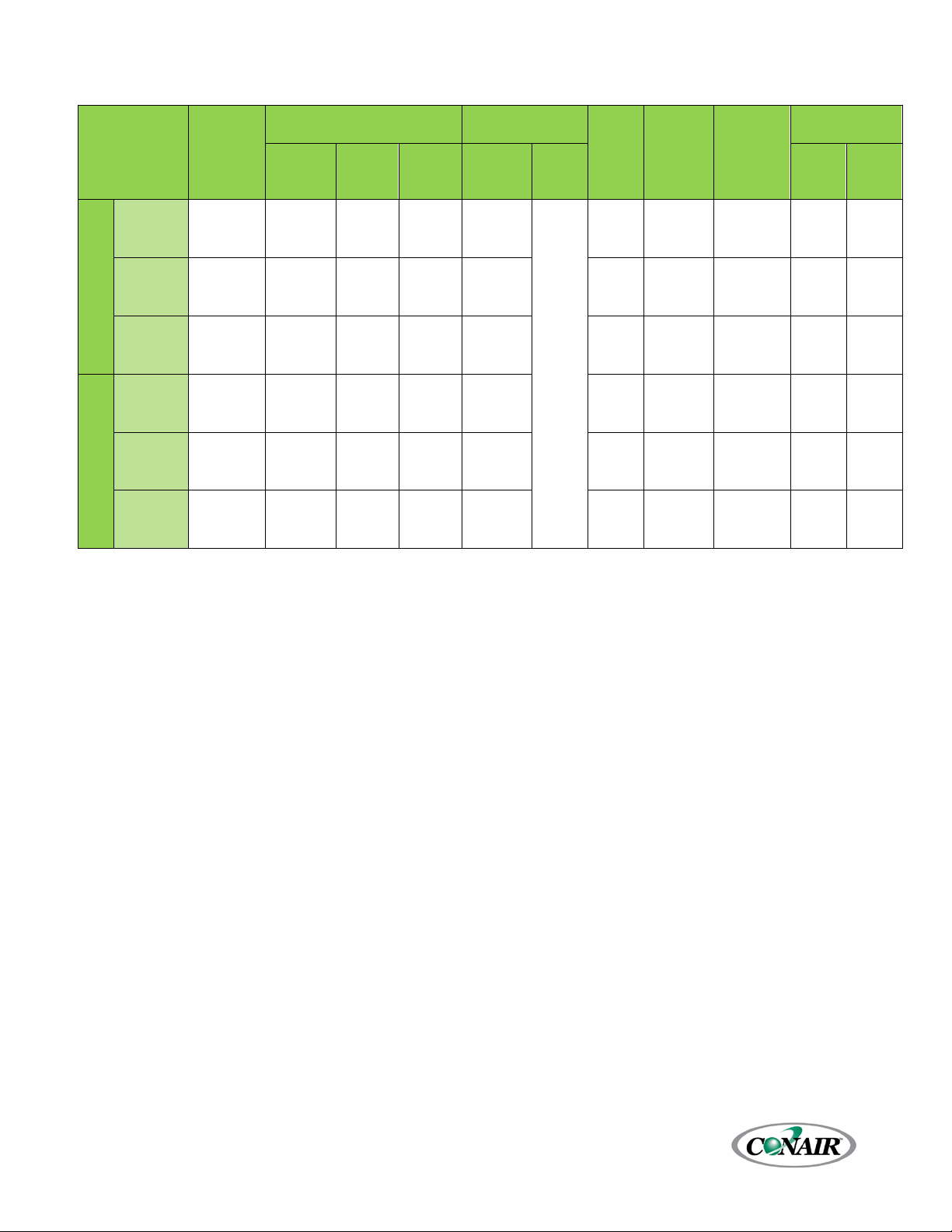
Figure 1 – Standard Flow Chiller Coolant Circuit Pressure Drop (10 through 30 Ton Single-Circuit Chillers) ............... 11
Figure 2 – Standard Flow Chiller Coolant Circuit Pressure Drop (40 through 80 Ton Single-Circuit Chillers) ............... 12
Figure 3 – Standard Flow Chiller Coolant Circuit Pressure Drop (20 through 160 ton Dual-Circuit Chillers) ................. 13
Figure 4 – Standard Flow Chiller Coolant Circuit Pressure Drop (80 through 160 ton Dual-Circuit Chillers) ................. 14
Figure 5 – High Flow Chiller Coolant Circuit Pressure Drop (10 through 25 ton Single-Circuit Chillers) ......................... 15
Figure 6 – High Flow Chiller Coolant Pressure Drop (30 through 50 ton Single-Circuit Chillers) ....................................... 16
Figure 7 – High Flow Chiller Coolant Pressure Drop (20 through 50 ton Dual-Circuit Chillers) .......................................... 17
Figure 8 – High Flow Chiller Coolant Pressure Drop (60 through 100 ton Dual-Circuit Chillers) ........................................ 18
Figure 9 – Condenser Water Circuit Pressure Drop (10 through 30 ton Single-Circuit Chillers) ......................................... 19
Figure 10 – Condenser Water Circuit Pressure Drop (40 through 80 ton Single-Circuit Chillers) ....................................... 20
Figure 11 – Condenser Water Circuit Pressure Drop (20 through 60 ton Dual-Circuit Chillers) .......................................... 21
Figure 12 – Condenser Water Circuit Pressure Drop (80 through 160 ton Dual-Circuit Chillers) ....................................... 22
Installation - Remote Air-Cooled Condenser ................................................................................................................ 23
Location ....................................................................................................................................................................................................................... 23
Mounted Legs and Lifting (10 ton Single-Circuit and 20-ton Dual-Circuit Units) ......................................................................... 24
Mounted Legs and Lifting (all except 10 ton Single-Circuit and 20-ton Dual-Circuit Units)..................................................... 25
Interconnecting Refrigerant Piping .................................................................................................................................................................. 26
Refrigeration Piping Design ................................................................................................................................................................................ 26
Figure 13 – Condenser Located with No Elevation Difference .......................................................................................................... 27
Figure 14 – Condenser Located above Chiller Unit................................................................................................................................ 27
Figure 15 - Condenser Located Below Chiller Unit ................................................................................................................................ 28
Determining Equivalent Line Length ................................................................................................................................................................ 28
Table 6 – Equivalent Lengths of Fittings ..................................................................................................................................................... 29
Liquid Line Sizing ..................................................................................................................................................................................................... 29
Table 7 – Liquid Line Sizes for R410A .......................................................................................................................................................... 30
Corporate Office: 724.584.5500 Instant Access 24/7 (Parts and Service): 800.458.1960 Parts and Service: 814.437.6861
Page 5

Discharge (Hot Gas) Line Sizing ......................................................................................................................................................................... 32
Figure 16 – Vertical Riser Traps ...................................................................................................................................................................... 32
Figure 17 - Double Discharge Riser.............................................................................................................................................................. 33
Table 8 – Discharge Line Sizes for Chiller (inches OD) ......................................................................................................................... 33
Table 9 - Upflow Discharge Line Sizes for R410A (inches OD) .......................................................................................................... 34
Calculating System Refrigerant and Oil Charge .......................................................................................................................................... 34
Table 10 – Combined Chiller and Remote Condenser Summer Refrigerant Charge ............................................................... 34
Table 11 - Field Piping R-410A Refrigerant Charge per 100 Feet of Run (Lbs.) ......................................................................... 34
Oil Charge Determination .................................................................................................................................................................................... 35
Setting Condenser Fan Controls ........................................................................................................................................................................ 35
Table 12 - Condenser Fan Pressure Settings (psig) ............................................................................................................................... 35
Installation - Electrical ...................................................................................................................................................... 36
Table 13 – ESEW & ESER Single-Circuit Chiller Electrical Data (60 Hz) .......................................................................................... 37
Table 14 – ESEW & ESER Single-Circuit Chiller with Standard Flow Pump Set Electrical Data (60 Hz) ............................. 38
Table 15 – ESEW & ESER Single-Circuit Chiller with High Flow Pump Set 1 Electrical Data (60 Hz) .................................. 39
Table 16 – ESEW & ESER Single-Circuit Chiller with High Flow Pump Set 2 Electrical Data (60 Hz) .................................. Error! Book
Table 17 – ESEW & ESER Dual-Circuit Chiller Electrical Data (60 Hz) ............................................................................................. 40
Table 18 – ESEW & ESER Dual-Circuit Chiller with Standard Flow Pump Set Electrical Data (60 Hz) ................................ 41
Table 19 – ESEW & ESER Dual-Circuit Chiller with High Flow Pump Set 1 Electrical Data (60 Hz) ..................................... 42
Table 20 – ESEW & ESER Dual-Circuit Chiller with High Flow Pump Set 2 Electrical Data (60 Hz) ..................................... Error! Book
Table 21 – Single-Circuit Remote Condenser Electrical Data (60 Hz) ............................................................................................. 43
Table 22 – Dual-Circuit Remote Condenser Electrical Data (60 Hz) ................................................................................................ 44
General Control Operation ............................................................................................................................................... 45
System Initialization ................................................................................................................................................................................................ 45
Figure 18 – Start-Up Splash Screen .............................................................................................................................................................. 45
Home - System Overview ................................................................................................................................................. 46
System Overview ...................................................................................................................................................................................................... 46
Figure 19 – ESEW System Overview ............................................................................................................................................................. 46
Figure 20 – ESER System Overview ............................................................................................................................................................... 46
Table 23 – System Overview Functions ....................................................................................................................................................... 46
Home – Full Screen ............................................................................................................................................................ 47
Figure 21 – Full Screen ...................................................................................................................................................................................... 47
Warnings ..................................................................................................................................................................................................................... 47
Figure 22 – Warning Screen ............................................................................................................................................................................ 47
Home – Pump Control (Optional) ................................................................................................................................... 48
Pump Control Screen (Optional) ....................................................................................................................................................................... 48
Figure 23 – Pump Control Screen ................................................................................................................................................................. 48
Pump VFD Control Screen (Optional) .............................................................................................................................................................. 48
Figure 24 – Pump VFD Control Screen ....................................................................................................................................................... 48
Menu 1 - Overview ............................................................................................................................................................ 49
Figure 25 – Menu 1 Screen .............................................................................................................................................................................. 49
Table 24 – Menu 1 Functions .......................................................................................................................................................................... 50
Menu 1 - Alarms................................................................................................................................................................. 51
Alarms Active ............................................................................................................................................................................................................. 51
Figure 26 – HMI Alarm Handler ..................................................................................................................................................................... 51
Alarm History ............................................................................................................................................................................................................. 51
Corporate Office: 724.584.5500 Instant Access 24/7 (Parts and Service): 800.458.1960 Parts and Service: 814.437.6861
Page 6

Figure 27 – Alarm History ................................................................................................................................................................................. 51
Alarm Setup ............................................................................................................................................................................................................... 52
Figure 28 – Alarm Setup ................................................................................................................................................................................... 52
Alarm Glycol ............................................................................................................................................................................................................... 52
Figure 29 – Alarm Setup ................................................................................................................................................................................... 52
Menu 1 – Metric Units/Imperial Units ............................................................................................................................ 53
Menu 1 - Compressor Data .............................................................................................................................................. 53
Compressor Data Screen ...................................................................................................................................................................................... 53
Figure 30 – Circuit Data Screen (Water-Cooled Condenser Chiller) ................................................................................................ 53
Figure 31 – Circuit Data Screen (Remote Air-Cooled Condenser Chiller) ..................................................................................... 54
Compressor Data Screen – Interlocks .............................................................................................................................................................. 54
Figure 32 – Interlocks ......................................................................................................................................................................................... 54
Figure 33 – Critical Interlocks .......................................................................................................................................................................... 55
Figure 34 – Refrigeration Interlocks ............................................................................................................................................................. 55
Menu 1 – Modbus/BAS ..................................................................................................................................................... 56
Modbus RTU/BAS Setup Screen ........................................................................................................................................................................ 56
Figure 35 – Modbus Setup Screen ................................................................................................................................................................ 56
Figure 36 – Modbus Word Data Screen ..................................................................................................................................................... 56
Figure 37 – Modbus Bit Data Screen ........................................................................................................................................................... 56
Menu 1 – EXV1 Expansion Valve Setup .......................................................................................................................... 57
EXV1 Expansion Valve Setup Screen ................................................................................................................................................................ 57
Figure 38 – EXV1 Expansion Valve Setup Screen .................................................................................................................................... 57
Table 25 – EXV1 Setup Parameters............................................................................................................................................................... 57
Menu 1 – EXV2 Hot Gas Bypass Setup ............................................................................................................................ 58
EXV2 Hot Gas Bypass Setup Screen (Optional)............................................................................................................................................ 58
Figure 39 – EXV2 Hot Gas Bypass Screen .................................................................................................................................................. 58
Table 26 – EXV2 Setup Parameters............................................................................................................................................................... 58
Menu 1 – Water Regulating Valve (WRV) Setup .......................................................................................................... 59
WRV Water Regulating Valve Setup Screen ................................................................................................................................................. 59
Figure 40 – WRV Setup Screen....................................................................................................................................................................... 59
Table 27 – WRV Setup Parameters ............................................................................................................................................................... 59
Menu 1 – Compressor Staging/PID ................................................................................................................................. 60
Compressor Staging Setup Screen ................................................................................................................................................................... 60
Figure 41 – Compressor Staging Setup Screen ....................................................................................................................................... 60
Table 28 – Compressor Staging Setup Parameters ................................................................................................................................ 60
Compressor Staging Graph Screen .................................................................................................................................................................. 61
Figure 42 – Compressor Staging Graph Screen ...................................................................................................................................... 61
Table 29 – Compressor Staging Graph Parameters ............................................................................................................................... 61
Compressor Staging Local Screen .................................................................................................................................................................... 62
Figure 43 – Compressor Staging Local Screen ........................................................................................................................................ 62
Table 30 – Compressor Staging Local Parameters ................................................................................................................................. 62
Menu 1 – Inputs/Outputs ................................................................................................................................................. 63
Inputs / Outputs Screens ...................................................................................................................................................................................... 63
Figure 44 – Digital Inputs Screen .................................................................................................................................................................. 63
Figure 45 – Digital Outputs Screen .............................................................................................................................................................. 63
Figure 46 – Analog Inputs Screen ................................................................................................................................................................. 63
Corporate Office: 724.584.5500 Instant Access 24/7 (Parts and Service): 800.458.1960 Parts and Service: 814.437.6861
Page 7

Figure 47 – Analog Outputs Screen ............................................................................................................................................................. 63
Menu 1 – Temperature Offsets ........................................................................................................................................ 64
RTD Temperature Offset Adjustment .............................................................................................................................................................. 64
Figure 48 – RTD Temperature Offsets Screen .......................................................................................................................................... 64
Menu 1 – Process Control ................................................................................................................................................. 65
Leaving/Entering Sensor Selection ................................................................................................................................................................... 65
Figure 49 – Process Control Screen .............................................................................................................................................................. 65
Menu 1 – Pumps Setup ..................................................................................................................................................... 66
Pump Setup Screen ................................................................................................................................................................................................. 66
Figure 50 – Pump Setup Screen ..................................................................................................................................................................... 66
Table 31 – Pump Setup Parameters ............................................................................................................................................................. 66
Menu 1 – Tank Setup ......................................................................................................................................................... 67
Tank Setup Screen ................................................................................................................................................................................................... 67
Figure 51 – Tank Setup Screen ....................................................................................................................................................................... 67
Menu 1 – Counters ............................................................................................................................................................. 68
Counters Screens ..................................................................................................................................................................................................... 68
Figure 52 – Counters 1 Screen ....................................................................................................................................................................... 68
Figure 53 – Counters 2 Screen ....................................................................................................................................................................... 68
Figure 54 – Counters 3 Screen ....................................................................................................................................................................... 68
Menu 2 - Overview ............................................................................................................................................................ 69
Figure 55 – Menu 2 ............................................................................................................................................................................................. 69
Table 32 – Menu 2 Functions .......................................................................................................................................................................... 69
Menu 2 – Hardware Options Selected ............................................................................................................................ 70
Hardware Options Screen .................................................................................................................................................................................... 70
Figure 56 – Hardware Options Screen ........................................................................................................................................................ 70
Menu 2 - Date/Time .......................................................................................................................................................... 71
Menu 2 – System Menu .................................................................................................................................................... 71
Menu 2 – Defaults .............................................................................................................................................................. 71
Figure 57 – Restore Factory Settings ........................................................................................................................................................... 71
Figure 58 – Factory Settings Restored ........................................................................................................................................................ 72
Menu 2 – Remote Setpoint Setup ................................................................................................................................... 72
Figure 59 – Remote Setpoint Setup Screen .............................................................................................................................................. 72
Menu 2 – Remove SD Storage ......................................................................................................................................... 73
Menu 2 – Trending ............................................................................................................................................................ 73
Figure 60 – Trending Screen ........................................................................................................................................................................... 73
Menu 2 – Remote Mode ................................................................................................................................................... 73
Menu 2 – PLC Link Setup .................................................................................................................................................. 74
PLC Link (Master/Slave) Setup Screen ............................................................................................................................................................. 74
Figure 61 – PLC Link Setup Screen ............................................................................................................................................................... 74
Figure 62 – PLC Link Word Data Screen ..................................................................................................................................................... 74
Figure 63 – PLC Link Bit Data Screen ........................................................................................................................................................... 74
Menu 2 – Touch Calibration ............................................................................................................................................. 75
Corporate Office: 724.584.5500 Instant Access 24/7 (Parts and Service): 800.458.1960 Parts and Service: 814.437.6861
Page 8

Start-Up ............................................................................................................................................................................... 75
Step 1 - Connect Main Power ............................................................................................................................................................................. 75
Step 2 - Fill Coolant Circuit .................................................................................................................................................................................. 76
System Fill Water Chemistry Requirements .............................................................................................................................................. 76
Table 33 – Fill Water Chemistry Requirements ........................................................................................................................................ 77
Table 34 - Recommended Glycol Solutions .............................................................................................................................................. 77
Step 3 - Check Condenser .................................................................................................................................................................................... 77
Water-Cooled Condenser Check ................................................................................................................................................................... 77
Remote Air-Cooled Condenser Check ........................................................................................................................................................ 77
Step 4 – Check Refrigerant Valves .................................................................................................................................................................... 77
Step 5 – Verify Freezestat Setting ..................................................................................................................................................................... 78
Step 6 – Turn On Control Power ........................................................................................................................................................................ 78
Step 7 – Establish Coolant Flow ......................................................................................................................................................................... 78
Step 8 – Intial Unit Operation ............................................................................................................................................................................. 78
Low-Ambient Start-Up (Remote Condensers) ......................................................................................................................................... 78
Preventive Maintenance ................................................................................................................................................... 79
Once a Week ............................................................................................................................................................................................................. 79
Once a Month ........................................................................................................................................................................................................... 80
Once Every Three Months .................................................................................................................................................................................... 80
Once a Year ................................................................................................................................................................................................................ 80
Cleaning the Operator Interface ...................................................................................................................................... 81
General Troubleshooting .................................................................................................................................................. 82
Preventive Maintenance Checklist .................................................................................................................................. 83
Drawings ............................................................................................................................................................................. 83
Warranty Information ....................................................................................................................................................... 84
Corporate Office: 724.584.5500 Instant Access 24/7 (Parts and Service): 800.458.1960 Parts and Service: 814.437.6861
Page 9

Page Intentionally Blank
Corporate Office: 724.584.5500 Instant Access 24/7 (Parts and Service): 800.458.1960 Parts and Service: 814.437.6861
Page 10

Foreword
The central chiller contains on or more refrigeration
circuits intended to chiller or cool a process fluid. As
an option, a process fluid reservoir and pumping
system is available to create a complete packaged
chiller system.
The intent of this manual is to serve as a guide for
placing our central chiller in service and operating
and maintaining it properly. Improper installation
can lead to poor equipment performance or severe
equipment damage. Failure to follow the installation
instructions may result in damage not covered by
your warranty. It is extremely important that a
qualified refrigeration installation contractor perform
all installation line sizing and piping. Please supply
these instructions to your authorized refrigeration
contractor. This manual is for our standard product
line with supplements as required to accommodate
any special items provided for a specific application.
The written information contained in this manual, as
well as various drawings, are intended to be general
in nature. Unit specific drawings are included with
the equipment for troubleshooting and servicing of
the unit. Additional copies of drawings are available
upon request. We strive to maintain an accurate
record of all equipment during the course of its
useful life.
Due to the ever-changing nature of applicable
codes, ordinances, and other local laws pertaining to
the use and operation of this equipment we do not
reference them in this manual. There is no substitute
for common sense and good operating practices
when placing any mechanical equipment into
operation. We encourage all personnel to familiarize
themselves with this manual's contents. Failure to do
so may unnecessarily prolong equipment down time.
The chiller uses chemical refrigerants for heat
transfer purposes. This chemical is sealed and tested
in a pressurized system containing ASME coded
vessels; however, a system failure will release it.
Refrigerant gas can cause toxic fumes if exposed to
fire. Place these units in a well-ventilated area,
especially if open flames are present.
Failure to follow these instructions could result in a
hazardous condition. The standard refrigerant used
in these units is a hydro fluorocarbon (HFC) trade
named R-410A. We strongly recommend a
refrigerant management program be implemented
which includes a survey of all equipment to
document the type and quantity of refrigerant in
each machine. In addition, we recommend only
licensed and EPA certified service technicians work
on our refrigeration circuits. Follow good piping
practices and the information in this manual to
ensure successful installation and operation of this
equipment. We are not responsible for liabilities
created by substandard piping methods and
installation practices external to the chiller.
We trust your equipment will have a long and useful
life. If you should have any questions, please contact
the Conair Service Department specifying the serial
number and model number of the unit as indicated
on the nameplate.
Corporate Office: 724.584.5500 Instant Access 24/7 (Parts and Service): 800.458.1960 Parts and Service: 814.437.6861
1
Page 11
General Warning
High Voltage Warning
Sharp Element Warning
Hot Surface Warning
Flammable Material Warning
Explosive Material Warning
General Mandatory Action
Wear Eye Protection
Wear Protection Gloves
Wear Ear Protection
Disconnect Before Carrying Out Maintenance or
Connect an Earth Terminal to Ground
WARNING: Any use or misuse of this equipment
harm.
WARNING: Vent all refrigerant relief valves in
displace oxygen and cause suffocation.
WARNING: This equipment contains hazardous
WARNING: This equipment contains refrigerant
property damage.
WARNING: This equipment may contain fan
in place.
WARNING: The exposed surfaces of motors,
CAUTION: Disconnect and lock out incoming
opening access panels for repair or maintenance.
CAUTION: Wear eye protection when installing,
protect against any sparks, debris, or fluid leaks.
CAUTION: The chiller will exceed 70 dBA sound
chiller.
CAUTION: Wear protective gloves when
or fluid leaks.
Safety Guidelines
Observe all safety precautions during installation,
start-up, and service of this equipment. The
following is a list of symbols used in this manual and
their meaning.
outside of the design intent may cause injury or
accordance to ANSI/ASHRAE Standard 15, Safety
Code for Mechanical Refrigeration. This
equipment should be located within a wellventilated area. Inhalation of refrigerant can be
hazardous to your health and the accumulation
of refrigerant within an enclosed space can
voltages that can cause severe injury or death.
under pressure. Accidental release of refrigerant
under pressure can cause personal injury and or
blades or other sharp edges. Make sure all fan
guards and other protective shields are securely
Repair
Only qualified personnel should install, start-up, and
service this equipment. When working on this
equipment, observe precautions in literature, and on
tags, stickers, and labels located on the equipment.
Corporate Office: 724.584.5500 Instant Access 24/7 (Parts and Service): 800.458.1960 Parts and Service: 814.437.6861
2
refrigerant piping, and other fluid circuit
components can be very hot and can cause burns
if touched with unprotected hands.
power before installing, servicing, or
maintaining the equipment. Connecting power to
the main terminal block energizes the entire
electric circuitry of the unit. A power supply
provides 24 VDC control power. Electric power at
the main disconnect should be shut off before
maintaining, or repairing the equipment to
pressure at 1 meter distance and 1 meter
elevation when operating. Wear ear protection
as required for personnel comfort when
operating or working in close proximity to the
installing, maintaining, or repairing the
equipment to protect against any sparks, debris,
Page 12

ESEW-
ESEW-
ESEW-
ESEW-
ESEW-
ESEW-
ESEW-
ESEW-
ESEW-
010S
015S
020S
025S
030S
040S
050S
060S
080S
General
Cooling Capacity tons
1
Set Point Range °F
Process In/Out (in.)-Standard
3 3 4
Process In/Out (in.)-High Flow
4 4
Condenser Water In/Out (in.)
3 4 4
Refrigerant Charge (lbs of
R410A)
70 80
Min Unloaded Capacity ton
with HGBP Option ton
A - Length inches {mm}
68 {1727}
68 {1727}
68 {1727}
68 {1727}
72 {1829}
100 {2540}
100 {2540}
100 {2540}
105 {2667}
B - Width inches {mm}
24 {610}
24 {610}
24 {610}
24 {610}
24 {610}
24 {610}
30 {762}
30 {762}
30 {762}
C- Height inches {mm}
69 {1753}
69 {1753}
69 {1753}
69 {1753}
69 {1753}
69 {1753}
69 {1753}
69 {1753}
69 {1753}
Ship Weight lbs {kg}
1200 {544}
1300 {590}
1400 {635}
1500 {680}
1600 {726}
1800 {816}
2000 {907}
2200 {998}
2400 {1089}
Operating Weight lbs {kg}
1400 {635}
1500 {680}
1600 {726}
1700 {771}
1800 {816}
2000 {907}
2200 {998}
2400 {1089}
2600 {1179}
MCA @ 460/3/60 amps
2
22
34
42
53
62
71
86
124
165
Reservoir Capacity gal {l}
275 {1041}
275 {1041}
275 {1041}
275 {1041}
275 {1041}
275 {1041}
275 {1041}
450 {1703}
450 {1703}
(Process/Chiller)
5D/1.5A
5D/1.5A
5D/1.5A
5D/1.5A
7.5D/2A
10D/2A
10D/3A
10D/3A
15D/3A
Process Connection Size inch
1½
1½ 2 2
2½
2½ 3 3
4
D - Length inches {mm}
84 {2134}
84 {2134}
84 {2134}
96 {2438}
96 {2438}
96 {2438}
96 {2438}
108 {2743}
108 {2743}
E - Width inches {mm}
72 {1829}
72 {1829}
76 {1930}
76 {1930}
76 {1930}
92 {2337}
92 {2337}
95 {2413}
100 {2540}
F - Height inches {mm}
75 {1905}
75 {1905}
75 {1905}
75 {1905}
75 {1905}
75 {1905}
75 {1905}
75 {1905}
75 {1905}
Ship Weight lbs {kg}
Operating Weight lbs {kg}
MCA @ 460/3/60 amps
2
Reservoir Capacity gal {l}
400 {1514}
400 {1514}
400 {1514}
400 {1514}
400 {1514}
400 {1514}
400 {1514}
650 {2461}
650 {2461}
Pump Models
(Process/Chiller)
5D/1.5A
7.5D/1.5A
10D/1.5A
10D/1.5A
10D/2A
15D/2A
15D/3A
20D/3A
25D/3A
Process Connection Size
inches
2
2½
2½ 3 3 4 4 4 6
D - Length inches {mm}
84 {2134}
84 {2134}
84 {2134}
84 {2134}
120 {3048}
132 {3353}
132 {3353}
132 {3353}
132 {3353}
E - Width inches {mm}
72 {1829}
72 {1829}
72 {1829}
76 {1930}
76 {1930}
92 {2337}
92 {2337}
92 {2337}
92 {2337}
F - Height inches {mm}
76 {1930}
76 {1930}
76 {1930}
76 {1930}
76 {1930}
76 {1930}
76 {1930}
76 {1930}
76 {1930}
Operating Weight lbs {kg}
MCA @ 460/3/60 amps
2
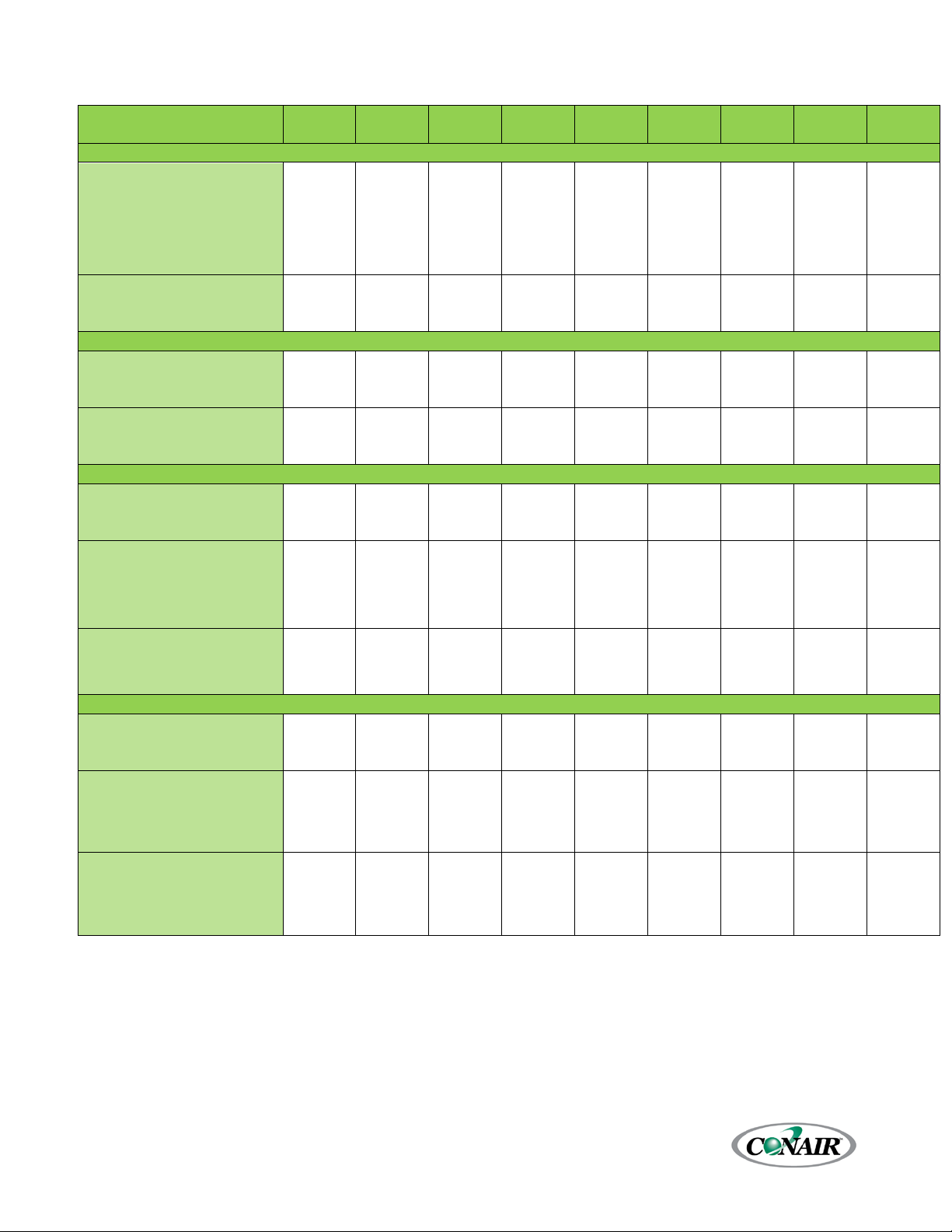
General Data
Table 1 – ESEW Series Single-Circuit Water-Cooled Condenser Chiller General Data (60 Hz)
Model
10.9 16.1 22.1 27.3 32.6 42.2
20 to 80 20 to 80 20 to 80 20 to 80 20 to 80 20 to 80
1½ 1½ 2 2 2½ 2½
2 2½ 2½ 3 3 4
1½ 2 2 2½ 2½ 3
10 30 30 35 40 50
5.5 8.1 11.1 13.7 16.2 21.0
2.7 4.0 5.5 6.8 8.1 10.5
53.3
20 to 80
25.9
13.0
Dimensions, Weights, Amps (Chiller Only)
Dimensions, Weights, Amps (Chiller with Standard Flow Reservoir Option , 10°F ∆T Process, 10°F ∆T Chiller)
Pump Models
68.4
20 to 80
33.9
17.0
86.2
20 to 80
N/A
100
42.6
21.3
2600 {1179} 2700 {1225} 2900 {1315} 3200 {1451} 3900 {1769} 4100 {1860} 4700 {2132} 5100 {2313} 5400 {2449}
4900 {2223} 5000 {2268} 5100 {2313} 5500 {2495} 6200 {2812} 6400 {2903} 7000 {3175} 7400 {3357} 7800 {3538}
32 43 50 62 75 86
104
Dimensions, Weights, Amps (Chiller with High Flow Reservoir Option 1, 5°F ∆T Process, 10°F ∆T Chiller)
Ship Weight lbs {kg}
1
Cooling capacity when cooling water with 50°F {10°C} set point, 60°F {16°C} return, 85°F {29°C} condenser water, R-410A
refrigerant.
2
MCA is Minimum Circuit Amps (for wire sizing), complie with NEC, Section 430-24.
2800 {1270} 2900 {1315} 3100 {1406} 3400 {1542} 4100 {1860} 4300 {1950} 4900 {2223} 5350 {2427} 5650 {2563}
5960 {2699} 6050 {2744} 6150 {2790} 6550 {2971} 7250 {3289} 7450 {3379} 8050 {3651} 9050 {4105} 9450 {4286}
32 46 57 68 78 91
109
Corporate Office: 724.584.5500 Instant Access 24/7 (Parts and Service): 800.458.1960 Parts and Service: 814.437.6861
3
141
153
188
201
Page 13
ESEW-
ESEW-
ESEW-
ESEW-
ESEW-
ESEW-
ESEW-
ESEW-
ESEW-
020D
030D
040D
050D
060D
080D
0100D
0120D
0160D
General
Cooling Capacity tons
1
Set Point Range °F
Process In/Out (in.)-Standard
Process In/Out (in.)-High Flow
Condenser Water In/Out
inches
Refrig Charge/Cir (lbs of R410A)
Mini Unloaded Capacity ton
Dimensions, Weights, Amps (Chiller Only)
A - Length inches {mm}
75 {1905}
75 {1905}
80 {2032}
80 {2032}
85 {2159}
115 {2921}
115 {2921}
118 {2997}
125 {3175}
B - Width inches {mm}
56 {1422}
56 {1422}
56 {1422}
56 {1422}
56 {1422}
56 {1422}
56 {1422}
56 {1422}
56 {1422}
C- Height inches {mm}
69 {1753}
69 {1753}
69 {1753}
69 {1753}
69 {1753}}
69 {1753}
69 {1753}
69 {1753}
69 {1753}
Ship Weight lbs {kg}
2500 {1134}
2600 {1179}
2800 {1270}
3000 {1361}
3200 {1451}
3600 {1633}
4000 {1814}
4400 {1996}
4800 {2177}
Operating Weight lbs {kg}
2700 {1225}
2800 {1270}
3000 {1361}
3200 {1451}
3400 {1542}
3800 {1724}
4200 {1905}
4600 {2087}
5000 {2268}
MCA @ 460/3/60 amps
2
42
63
76
99
115
131
161
232
311
Dimensions, Weights, Amps (Chiller with Standard Flow Reservoir Option , 10°F ∆T Process, 10°F ∆T Chiller)
Reservoir Size gal {l}
Pump Models (Process/Chiller)
Process Connection Size inch
78 {1981}
78 {1981}
78 {1981}
90 {2286}
90 {2286}
1053
1103
1103
1103
F - Height inches {mm}
Ship Weight lbs {kg}
10450
{4740}
MCA @ 460/3/60 amps
2
Dimensions, Weights, Amps (Chiller with High Flow Reservoir Option 1, 5°F ∆T Process, 10°F ∆T Chiller)
Reservoir Size gal {l}
Pump Models (Process/Chiller)
10D/1.5A
Process Connection Size inch
78 {1981}
78 {1981}
78 {1981}
90 {2286}
90 {2286}
1053
{26746}
1103
{28016}
1103
{28016}
1103
{28016}
F - Height inches {mm}
76 {1930}
76 {1930}
76 {1930}}
76 {1930}
76 {1930}
90 {2286}
90 {2286}
90 {2286}
Operating Weight lbs {kg}
7450 {3379}
7650 {3470}
7750 {3515}
8050 {3651}
9350 {4241}
9500 {4332}
11000
11400
11800
MCA @ 460/3/60 amps
2
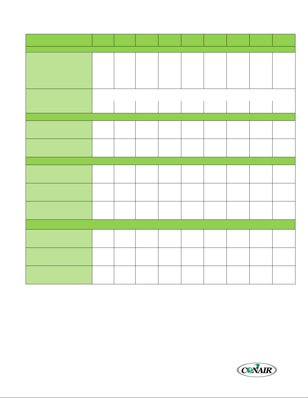
Table 2 – ESEW Series Dual-Circuit Water-Cooled Condenser Chiller General Data (60 Hz)
21.7 32.1 44.3 54.7 65.2 84.5 106.7 136.9 172.5
20 to 80 20 to 80 20 to 80 20 to 80 20 to 80 20 to 80 20 to 80 20 to 80 20 to 80
2 2½ 2½ 3 3 4 4 4 6
2½ 3 4 4 4 6 6 6 N/A
2 2½ 3 3 4 4 4 6 6
10 30 30 35 40 50 70 80 100
5.5 8.0 11.1 13.7 16.2 20.9 25.9 33.9 42.6
with HGBP Option ton
2.7 4.0 5.5 6.8 8.1 10.5 13.0 16.9 21.3
275 {1041} 275 {1041} 275 {1041} 275 {1041} 450 {1703} 450 {1703} 700 {2650} 700 {2650} 1000 {3785}
5D/1.5A 7.5D/2A 10D/2A 10D/3A 10D/3A 15D/3A 15D/5A 20D/7.5F 25D/10E
2 2½ 2½ 3 3 4 4 4 6
D - Length inches {mm}
E - Width inches {mm}
108 {2743} 108 {2743} 108 {2743} 120 {3048} 132 {3353} 132 {3353} 132 {3353} 144 {3658} 144 {3658}
{26746}
{28016}
{28016}
75 {1905} 75 {1905} 75 {1905} 75 {1905} 75 {1905}} 75 {1905} 75 {1905} 75 {1905} 90 {2286}
4100 {1860} 4300 {1950} 4400 {1996} 4700 {2132} 5400 {2449} 5600 {2540} 6200 {2812} 6600 {2994} 7000 {3175}
Operating Weight lbs {kg}
6400 {2903} 6600 {2994} 6700 {3039} 7000 {3175} 7700 {3493} 7900 {3583} 8500 {3856} 8900 {4037}
51 76 93 117 133 154 187 269 356
400 {1514} 400 {1514} 400 {1514} 400 {1514} 650 {2461} 650 {2461} 1000 {3785} 1000 {3785} 1000 {3785}
10D/2A 15D/2A 15D/3A 20D/3A 25D/3A 30D/5A 40D/7.5F 40D/10E
2½ 3 4 4 4 6 6 6 6
D - Length inches {mm}
108 {2743} 108 {2743} 108 {2743} 120 {3048} 132 {3353} 132 {3353} 144 {3658} 144 {3658} 144 {3658}
E - Width inches {mm}
Ship Weight lbs {kg}
1
Cooling capacity when cooling water with 50°F {10°C} set point, 60°F {16°C} return, 85°F {29°C} condenser water, R-410A
refrigerant.
2
MCA is Minimum Circuit Amps (for wire sizing), complies with NEC, Section 430-24
3
To keep the shipping dimensions within a 102” width for standard flatbed shipping, the condenser inlet manifold is removed
for shipment.
4300 {1950} 4500 {2041} 4600 {2087} 4900 {2223} 5650 {2563} 5850 {2654} 6500 {2948} 6900 {3130} 7300 {3311}
{4990}
{5171}
59 79 98 122 145 168 207 294 375
Corporate Office: 724.584.5500 Instant Access 24/7 (Parts and Service): 800.458.1960 Parts and Service: 814.437.6861
4
{28016}
90 {2286}
{5352}
Page 14
ESER-
ESER-
ESER-
ESER-
ESER-
ESER-
ESER-
ESER-
ESER-
010S
015S
020S
025S
030S
040S
050S
060S
080S
General
Cooling Capacity tons
1
Set Point Range °F
Process In/Out (in.)-Standard
Process In/Out (in.)-High Flow
Refrigerant Discharge Line inch
Refrigerant Liquid Line inch
Refrigerant Charge (lbs of
R410A)
with HGBP Option ton
A - Length inches {mm}
68 {1727}
68 {1727}
68 {1727}
68 {1727}
72 {1829}
102 {2591}
102 {2591}
102 {2591}
105 {2667}
B - Width inches {mm}
24 {610}
24 {610}
24 {610}
24 {610}
24 {610}
24 {610}
30 {762}
30 {762}
30 {762}
C- Height inches {mm}
69 {1753}
69 {1753}
69 {1753}
69 {1753}
69 {1753}
69 {1753}
69 {1753}
69 {1753}
69 {1753}
Ship Weight lbs {kg}
1200 {544}
1300 {590}
1400 {635}
1500 {680}
1600 {726}
1800 {816}
2000 {907}
2200 {998}
2400 {1089}
Operating Weight lbs {kg}
1300 {590}
1400 {635}
1500 {680}
1600 {726}
1700 {771}
1900 {862}
2100 {953}
2300 {1043}
2500 {1134}
MCA @ 460/3/60 amps
2
22
34
42
53
62
71
86
124
165
Reservoir Capacity gal {l}
275 {1041}
275 {1041}
275 {1041}
275 {1041}
275 {1041}
275 {1041}
275 {1041}
450 {1703}
450 {1703}
Pump Models (Process/Chiller)
5D/1.5A
5D/1.5A
5D/1.5A
5D/1.5A
7.5D/2A
10D/2A
10D/3A
10D/3A
15D/3A
Process Connection Size inch
1½
1½ 2 2
2½
2½ 3 3
4
D - Length inches {mm}
84 {2134}
84 {2134}
84 {2134}
96 {2438}
96 {2438}
96 {2438}
96 {2438}
108 {2743}
108 {2743}
E - Width inches {mm}
64 {1626}
64 {1626}
64 {1626}
76 {1930}
76 {1930}
92 {2337}
92 {2337}
96 {2438}
98 {2489}
F - Height inches {mm}
75 {1905}
75 {1905}
75 {1905}
75 {1905}
75 {1905}
75 {1905}
75 {1905}
75 {1905}
75 {1905}
Ship Weight lbs {kg}
Operating Weight lbs {kg}
MCA @ 460/3/60 amps
2
Reservoir Capacity gal {l}
400 {1514}
400 {1514}
400 {1514}
400 {1514}
400 {1514}
400 {1514}
400 {1514}
650 {2460}
650 {2460}
Pump Models (Process/Chiller)
5D/1.5A
7.5D/1.5A
10D/1.5A
10D/1.5A
10D/2A
15D/2A
15D/3A
20D/3A
25D/3A
Process Connection Size inch
2
2½
2½ 3 3 4 4 4 6
D - Length inches {mm}
84 {2134}
84 {2134}
84 {2134}
96 {2438}
96 {2438}
96 {2438}
96 {2438}
108 {2743}
108 {2743}
E - Width inches {mm}
64 {1626}
64 {1626}
64 {1626}
76 {1930}
92 {2337}
92 {2337}
92 {2337}
96 {2438}
98 {2489}
F - Height inches {mm}
76 {1930}
76 {1930}
76 {1930}
76 {1930}
76 {1930}
76 {1930}
76 {1930}
76 {1930}
76 {1930}
Ship Weight lbs {kg}
Operating Weight lbs {kg}
MCA @ 460/3/60 amps
2
Table 3 – ESER Series Single-Circuit Remote Air-Cooled Condenser Chiller General Data (60 Hz)
10 14.9 20.4 25.2
20 to 80 20 to 80 20 to 80 20 to 80
1½ 1½ 2 2
2 2½ 2½ 3
⅞ 1⅛ 1⅛ 1⅜
⅝ ⅞ ⅞ 1⅛
30.1 38.9 48.9 63.6 78.7
20 to 80 20 to 80 20 to 80 20 to 80 20 to 80
2½ 2½ 3 3 4
3 4 4 4 N/A
1⅜ 1⅝ 1⅝ 1⅝ 2⅛
1⅛ 1⅛ 1⅛ 1⅜ 1⅝
Varies based on refrigerant system piping
Min Unloaded Capacity ton
5.0 7.4 10.0 12.5
2.5 3.7 5.0 6.2
14.8 19.1 23.6 30.9 38.5
7.4 9.6 11.8 15.5 19.3
Dimensions, Weights, Amps (Chiller Only)
Dimensions, Weights, Amps (Chiller with Standard Flow Reservoir Option , 10°F ∆T Process, 10°F ∆T Chiller)
2600 {1179} 2700 {1225} 2900 {1315} 3200 {1451} 3900 {1769}
4900 {2223} 5000 {2268} 5100 {2313} 5500 {2495} 6200 {2812} 6400 {2903} 7000 {3175} 7400 {3357} 7800 {3538}
32 43 50 62
4100 {1860} 4700 {2132} 5100 {2313} 5400 {2449}
75 86 104 141 188
Dimensions, Weights, Amps (Chiller with High Flow Reservoir Option 1, 5°F ∆T Process, 10°F ∆T Chiller)
2800 {1270} 2900 {1315} 3100 {1406} 3400 {1542} 4100 {1860} 4300 {1950} 4900 {2223} 5350 {2427} 5650 {2563}
5950 {2699} 6050 {2744} 6150 {2790} 6550 {2971} 7250 {3289} 7450 {3379} 8050 {3651} 9050 {4105} 9450 {4286}
1
Cooling capacity when cooling water with 50°F {10°C} set point, 60°F {16°C} return, 95°F {35°C} condenser air, R-410A
refrigerant.
2
MCA is Minimum Circuit Amps (for wire sizing).
32 46 57 68
78 91 109 153 201
Corporate Office: 724.584.5500 Instant Access 24/7 (Parts and Service): 800.458.1960 Parts and Service: 814.437.6861
5
Page 15

ESER-
ESER-
ESER-
ESER-
ESER-
ESER-
ESER-
ESER-
ESER-
020D
030D
040D
050D
060D
080D
0100D
0120D
0160D
General
Cooling Capacity tons
1
Set Point Range °F
Process In/Out (in.)-Standard
Process In/Out (in.)-High Flow
Refrig Discharge Line/Circuit
inches
Refrig Liquid Line/Circuit
inches
R410A)
Min Unloaded Capacity ton
with HGBP Option ton
A - Length inches {mm}
75 {1905}
75 {1905}
80 {2032}
80 {2032}
89 {2261}
105 {2667}
105 {2667}
110 {2794}
125 {3175}
B - Width inches {mm}
48 {1219}
48 {1219}
48 {1219}
48 {1219}
48 {1219}
48 {1219}
48 {1219}
48 {1219}
52 {1321}
C- Height inches {mm}
69 {1753}
69 {1753}
69 {1753}
69 {1753}
69 {1753}
69 {1753}
69 {1753}
69 {1753}
69 {1753}
Ship Weight lbs {kg}
2500 {1134}
2600 {1179}
2800 {1270}
3000 {1361}
3200 {1451}
3600 {1633}
4000 {1814}
4400 {1996}
4800 {2177}
Operating Weight lbs {kg}
2700 {1225}
2800 {1270}
3000 {1361}
3200 {1451}
3400 {1542}
3800 {1724}
4200 {1905}
4600 {2087}
5000 {2268}
MCA @ 460/3/60 amps
2
42
63
76
99
115
131
161
232
311
Reservoir Size gal {l}
275 [1041}
275 {1041}
275 {1041}
275 {1041}
450 {1703}
450 {1703}
700 {2650}
700 {2650}
1000 {3785}
Pump Models
(Process/Chiller)
5D/1.5A
7.5D/2A
10D/2A
10D/3A
10D/3A
15D/3A
15D/5A
20D/7.5F
20D/10E
Process Connection Size inch
6
D - Length inches {mm}
108 {2743}
108 {2743}
108 {2743}
120 {3048}
132 {3353}
132 {3353}
132 {3353}
144 {3658}
144 {3658}
E - Width inches {mm}
74 {1880}
74 {1880}
74 {1880}
74 {1880}
74 {1880}
92 {2337}
102 {2591}
102 {2591}
102 {2591}
F - Height inches {mm}
75 {1905}
75 {1905}
75 {1905}
75 {1905}
75 {1905}
75 {1905}
75 {1905}
75 {1905}
75 {1905}
Ship Weight lbs {kg}
6800 {3084}
Operating Weight lbs {kg}
9100 {4128}
MCA @ 460/3/60 amps
2
356
400 {1514}
400 {1514}
400 {1514}
400 {1514}
650 {2461}
650 {2461}
1000 {3785}
1000 {3785}
1000 {3785}
Pump Models
(Process/Chiller)
10D/1.5A
10D/2A
15D/2A
15D/3A
20D/3A
25D/3A
30D/5A
40D/7.5F
40D/10E
D - Length inches {mm}
108 {2743}
108 {2743}
108 {2743}
120 {3048}
132 {3353}
132 {3353}
132 {3353}
144 {3658}
144 {3658}
E - Width inches {mm}
74 {1880}
74 {1880}
74 {1880}
74 {1880}
74 {1880}
92 {2337}
102 {2591}
102 {2591}
102 {2591}
F - Height inches {mm}
76 {1930}
76 {1930}
76 {1930}
76 {1930}
76 {1930}
90 {2286}
90 {2286}
90 {2286}
90 {2286}
Operating Weight lbs {kg}
7250 {3289}
7350 {3334}
7450 {3379}
7850 {3561}
9150 {4150}
9350 {4241}
10800
11200
11160
MCA @ 460/3/60 amps
2
Table 4 – ESER Series Dual-Circuit Remote Air-Cooled Condenser Chiller General Data (60 Hz)
20.4 29.9 40.7 50.5 60.2 77.8 97.7 127.2 157.5
20 to 80 20 to 80 20 to 80 20 to 80 20 to 80 20 to 80 20 to 80 20 to 80 20 to 80
2 2½ 2½ 3 3 4 4 4 6
2½ 3 4 4 4 6 6 6 N/A
⅞ 1⅛ 1⅛ 1⅜ 1⅜ 1⅝ 1⅝ 1⅝ 2⅛
⅝ ⅞ ⅞ 1⅛ 1⅛ 1⅛ 1⅛ 1⅜ 1⅝
Refrig Charge/Cir (lbs of
Varies based on refrigeration system piping
5.0 7.3 10.0 12.5 14.7 19.1 23.6 30.9 38.5
2.5 3.7 5.0 6.2 7.4 9.6 11.8 15.5 19.3
Dimensions, Weights, Amps (Chiller Only)
Dimensions, Weights, Amps (Chiller with Standard Flow Reservoir Option , 10°F ∆T Process, 10°F ∆T Chiller)
2 2½ 2½ 3 3 4 4 4
3900 {1769} 4000 {1814} 4200 {1905} 4500 {2041} 5200 {2359} 5400 {2449} 6000 {2722} 6400 {2903}
6200 {2812} 6300 {2858} 6400 {2903} 6800 {3084} 7500 {3402} 7700 {3493} 8300 {3765} 8700 {3946}
51 76 93 117 133 154 187 269
Dimensions, Weights, Amps (Chiller with High Flow Reservoir Option 1, 5°F ∆T Process, 10°F ∆T Chiller)
Reservoir Size gal {l}
Process Connection Size inch
Ship Weight lbs {kg}
1
Cooling capacity when cooling water with 50°F{10°C} set point, 60°F {16°C} return, 95°F {35°C} condenser air, R-410A
refrigerant.
2
MCA is Minimum Circuit Amps (for wire sizing), complies with NEC, Section 430-24.
Corporate Office: 724.584.5500 Instant Access 24/7 (Parts and Service): 800.458.1960 Parts and Service: 814.437.6861
2½ 3 4 4 4 6 6 6 6
4100 {1860} 4200 {1905} 4400 {1996} 4700 {2132} 5450 {2472} 5650 {2563} 6300 {2858} 6700 {3039} 7100 {3221}
{4899}
{5080}
{5262}
59 79 98 122 145 168 207 294 375
6
Page 16
Chiller
Dimensions inches {mm}
Weights lbs {kg}
Total
Sound
MCA @
Refrig Lines
(in)
Inlet
Circuit
Outlet
Circuit
KCM014
Operating weight varies base on system refrigeration charge
and operating conditions
14,400
53
KCL023
24,000
63
KCL030
22,600
63
KCL037
20,600
63
KCL045
33,900
64
KCL056
30,900
64
KCL068
42,400
65
KCL095
51,800
66
KCL110
62,100
67
KCM034
28,400
55
KCL047
47,900
65
KCL060
45,200
65
KCL074
41,200
65
KCL090
67,800
67
KCL112
61,800
67
KCL137
84,800
68
KCL190
103,500
69
KCL224
124,200
70
Table 5 – Remote Air-Cooled Condenser General Data (60 Hz)
Model
Single-Circuit
Dual-Circuit
1
One condenser is required per chiller; dual-circuit chillers use one remote condenser that has two refrigeration circuits.
2
Sound pressure level at 30 feet.
3
MCA is Minimum Circuit Amps (for wire sizing) as provided by the remote condenser manufacturer.
Model
Used
1
With
ESER-010S 83 {2108} 43 {1092} 48 {1219} 415 {188}
ESER-015S 113 {2870} 45 {1143} 54 {1372} 670 {304}
ESER-020S 113 {2870} 45 {1143} 54 {1372} 720 {327}
ESER-025S 113 {2870} 45 {1143} 54 {1372} 800 {363}
ESER-030S 168 {4267} 45 {1143} 54 {1372} 1075 {488}
ESER-040S 168 {4267} 45 {1143} 54 {1372} 1200 {544}
ESER-050S 223 {5664} 45 {1143} 54 {1372} 1475 {669}
ESER-060S 278 {7061} 45 {1143} 54 {1372} 1950 {885}
ESER-080S 333 {8458} 45 {1143} 54 {1372} 2300 {1043}
ESER-020D 83 {2108} 83 {2108} 48 {1219} 830 {376}
ESER-030D 113 {2870} 87 {2210} 54 {1372} 1275 {578}
ESER-040D 113 {2870} 87 {2210} 54 {1372} 1350 {612}
ESER-050D 113 {2870} 87 {2210} 54 {1372} 1525 {692}
ESER-060D 168 {4267} 87 {2210} 54 {1372} 2050 {930}
ESER-080D 168 {4267} 87 {2210} 54 {1372} 2275 {1032}
ESER-0100D 223 {5664} 87 {2210} 54 {1372} 2800 {1270}
ESER-0120D 278 {7061} 87 {2210} 54 {1372} 3700 {1678}
ESER-0160D 333 {8458} 87 {2210} 54 {1372} 4400 {1996}
L W H Ship Oper
Air
Flow
(cfm)
Pressure
Level
(dBA)2
460/3/60
(amps)
2.6
7.0
7.0
7.0
10.1
10.1
16.0
16.0
21.0
4.9
16.0
16.0
16.0
21.0
21.0
24.8
36.0
46.0
3
Per
1⅜ 1⅛
2⅛ 1⅜
2⅛ 1⅝
2⅛ 1⅝
2⅝ 1⅝
2⅝ 2⅛
2⅝ 2⅛
3⅛ 2⅝
3⅛ 2⅝
1⅝ 1⅛
2⅛ 1⅜
2⅛ 1⅝
2⅛ 1⅝
2⅝ 1⅝
2⅝ 2⅛
2⅝ 2⅛
3⅛ 2⅝
3⅛ 2⅝
Per
Corporate Office: 724.584.5500 Instant Access 24/7 (Parts and Service): 800.458.1960 Parts and Service: 814.437.6861
7
Page 17

Pre-Installation
Receiving Inspection
When the unit arrives, verify it is the correct unit by
comparing the information that appears on the unit
nameplate with that which appears on the order
acknowledgement and shipping papers. Inspect the
equipment condition for any visible damage and
verify all items shown on the bill of lading are
present. If damage is evident, properly document it
on the delivery receipt and clearly mark any item
with damage as “unit damage” and notify the carrier.
In addition, make note of the specific damage and
notify Conair’s Service Department.
Shipping damage is the responsibility of the carrier.
To protect against possible loss due to damage
incurred during shipping and to expedite payment
for damages, it is important to follow proper
procedures and keep records. Photographs of
damaged equipment are excellent documentation
for your records.
Start unpacking the unit, inspect for concealed
damages, and take photos of any damages found.
Once received, equipment owners have the
responsibility to provide reasonable evidence that
the damage did not occur after delivery. Photos of
the equipment damage while the equipment is still
partially packed will help in this regard. Refrigerant
lines can be susceptible to damage in transit. Check
for broken lines, oil leaks, damaged controls, or any
other major component torn loose from its
mounting point.
Record any signs of concealed damage and file a
shipping damage claim immediately with the
shipping company. Most carriers require concealed
damages be reported within 15 days of receipt of
the equipment. In addition to notifying the carrier,
notify Conair’s Service Department.
Water-cooled chillers ship with a full refrigerant
charge while remote condenser chillers ship with a
nitrogen holding charge. Remote air-cooled
condensers ship separately with a 350-psi dry
nitrogen gas charge. Check the remote condenser
for signs of leaks prior to rigging. This will ensure no
coil damage has occurred after the unit left the
Corporate Office: 724.584.5500 Instant Access 24/7 (Parts and Service): 800.458.1960 Parts and Service: 814.437.6861
factory. The condenser ships with the legs removed.
Mount the legs to the condenser using the provided
nuts, bolts, and washers.
Unit Storage
If the chiller is stored prior to installation, it is
important to protect it from damage. Blow out any
water or fluid from the evaporator and water-cooled
condenser circuits to protect the unit from damage
from freezing. Close any open refrigerant valves.
Cover the equipment to keep dirt and debris from
accumulating on it. Units charged with refrigerant
should not be stored in areas warmer than
145°F (62.8°C).
8
Page 18

Installation - Chiller Mechanical
Unit Location
The chiller is available in many different
configurations to meet various environments. Please
refer to the proposal and order acknowledgement
for this equipment to verify the specific
environmental design conditions for your chiller.
Allow a minimum of 48 inches (1219mm) of
clearance between the remote condenser and any
walls or obstructions. For installations with multiple
condensers, allow a minimum of 96 inches (2438mm)
between condensers placed side-by-side or 48
inches (1219mm) for condensers placed end-to-end.
In all cases, install the equipment on a rigid surface
suitable to support the full operating weight of the
unit. Level all equipment to ensure proper operation.
When installed the equipment must be level within
¼ inch over its length and width.
Serviceability is an important factor to consider when
deciding on the location of the chiller. Do not
compromise this feature by locating it in an
inaccessible area. When locating the chiller it is
important to consider accessibility to the
components to allow for proper maintenance and
servicing of the unit. In general, allow a minimum of
36 inches (914mm) of clearance around all sides and
above the unit. There should be no piping or conduit
located over the unit. This will ensure easy access
with an overhead crane or lift for heavier
components should they need to be replaced or
serviced.
Proper ventilation is another important
consideration when locating the unit. Locate the unit
is an area that will not rise above 110°F (43.3°C).
In addition, ensure the condenser and evaporator
refrigerant pressure relief valves can vent in
accordance with all local and national codes.
Rigging
The chiller has a structural steel frame with forklift
slots to facilitate easy movement and positioning.
Follow proper rigging methods to prevent damage
to components. Avoid impact loading caused by
Corporate Office: 724.584.5500 Instant Access 24/7 (Parts and Service): 800.458.1960 Parts and Service: 814.437.6861
sudden jerking when lifting or lowering the chiller.
Use pads where abrasive surface contact may occur.
Use the frame supporting the unit for positioning it
with a crane or a forklift.
Chilled Water Piping
Proper insulation of chilled water piping is crucial to
prevent condensation. The formation of
condensation on chiller water piping, the state
change of the water from gas to liquid, adds a
substantial heat load to the system and becomes an
additional burden for the chiller.
The importance of properly sized piping between
the chiller and process cannot be overemphasized.
Reference the current edition of the ASHRAE
Fundamentals Handbook or other suitable design
guide for proper pipe sizing. In general, run full size
piping out to the process and then reduce the pipe
size to match the connections on the process
equipment. One of the most common causes of
unsatisfactory chiller performance is poor piping
system design. Avoid long lengths of hoses, quick
disconnect fittings, and manifolds wherever possible
as they offer high resistance to water flow. When
manifolds are required, install them as close to the
use point as possible. Provide flow-balancing valves
at each machine to assure adequate water
distribution in the entire system.
Condenser Water Piping
(Water-Cooled Condenser Chillers Only)
The performance of a condenser is dependent on
maintaining the proper flow and temperature of
water through the heat exchanger. Insufficient water
flow or high condenser water supply temperature
will result in the reduction of cooling capacity of the
chiller. Extreme conditions will eventually result in
the chiller shutting down due to high refrigerant
pressure. Allowing the condenser to plug up from
contaminants in the condenser water stream
adversely affects performance. In order to reduce
maintenance costs and chiller downtime, a water
treatment program is highly recommended for the
condenser cooling water. Contact our Customer
Service Department for assistance in the proper
procedure for cleaning out any plugged condenser.
9
Page 19

The nominal chiller design is for 85°F (38.6°C)
condenser cooling water supply. Under normal
operation under full load there will be about a 10°F
(4.5°C) rise through the condenser resulting in 95°F
(43.1°C) exiting water temperature from the
condenser. To ensure proper water flow through the
condenser, the condenser water pump should
provide at least 25 psi (1.7 bar).
Each condenser has a two-way condenser waterregulating valve. Under varying loads and condenser
inlet water temperatures the amount of cooling
water needed varies. The condenser waterregulating valve controls the amount of water
allowed to pass through the condenser in order to
maintain proper refrigeration pressures in the circuit.
To prevent damage to the condenser or regulating
valve, the condenser water pressure should not
exceed 150 psig (10.3 bar). The condenser water-
Mount the sensor in a ½” NPT coupling in a
minimum pipe size of 3”. The probe sheath is ¼” OD
x 3” in length and is equipped with a ½” NPT male
fitting for direct mounting in a coupling. The sensor
is to be direct immersion for the most accurate
reading and quickest response time. If direct
immersion mounting is not possible, mount the
sensor inside a thermowell to aid in maintenance
and or repair of the sensor if opening of the process
piping is not possible. Use a suitable heat transfer
compound with a thermowell. The sensor is
equipped with a NEMA-4 sensor head with an
integral temperature transmitter. Wiring must be
field provided from the sensor head to the chiller
electrical enclosure and landed at the designated
terminal blocks within the enclosure. Please see the
chiller electrical schematic provided for further
detail.
regulating valve controls the condenser water flow in
order to maintain the pressure set point. The chiller
load, condenser-water inlet temperature, and
pressure set point determine the actual flow.
Water Pressure Gauges
It is highly recommended to install pressure gauges
or taps in the inlet and outlet of both the condenser
and evaporator chilled water piping. The ability to
read the pressure drop across the chiller is important
and will aid in preventive maintenance and in
troubleshooting the chiller performance.
Master Temperature Sensor
This section only applies to installations where
multiple chillers are in a common system where one
chiller will be the master with the other chillers
serving as slaves. In those situations, a field-installed
master fluid-temperature sensor is required to be
field installed in the common chilled water supply
and return piping. The sensor ships loose from the
factory. The supply sensor should be installed
downstream of all individual chilled water supply
streams. Position the sensor to read the mixed
supply temperature. The supply sensor will normally
be the control sensor for the chilled water set point
and will determine the loading/unloading of the
compressors of the system.
Corporate Office: 724.584.5500 Instant Access 24/7 (Parts and Service): 800.458.1960 Parts and Service: 814.437.6861
10
Page 20
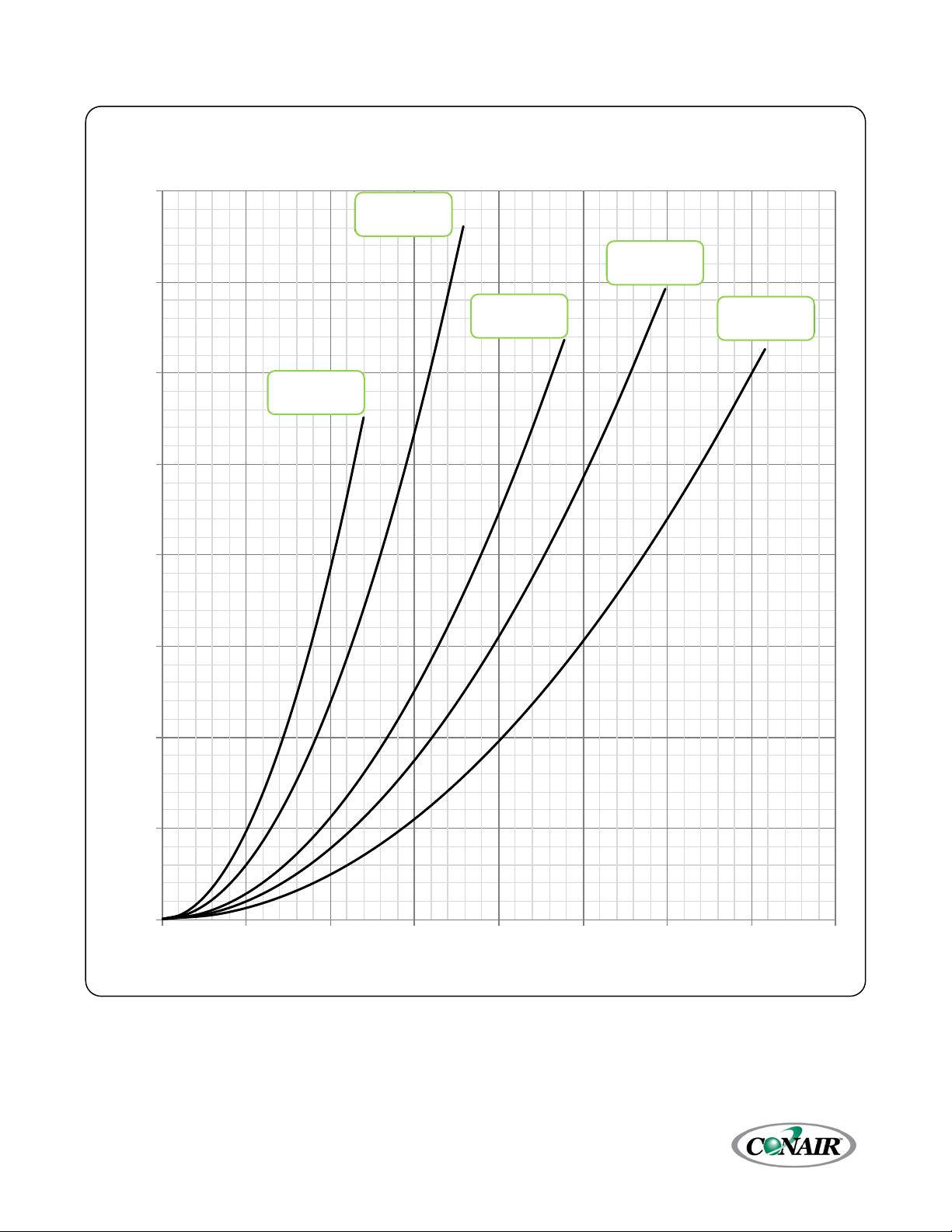
0
5
10
15
20
25
30
35
40
0 20 40 60 80 100 120 140 160
Pressure Loss (psi)
Flow (gpm)
Standard Flow Chiller Coolant Circuit Pressure Drop
(Water at 50°F)
TSEW15S
& T SER15S
TSEW20S
& T SER20S
TSEW25S
& T SER25S
TSEW30S
& T SER30S
TSEW10S
& T SER10S
Figure 1 – Standard Flow Chiller Coolant Circuit Pressure Drop (10 through 30 Ton Single-Circuit Chillers)
ESEW-015S
ESER-015S
ESEW-025S
ESER-025S
ESEW-020S
ESER-020S
ESEW-010S
ESER-010S
ESEW-030S
ESER-030S
Corporate Office: 724.584.5500 Instant Access 24/7 (Parts and Service): 800.458.1960 Parts and Service: 814.437.6861
11
Page 21
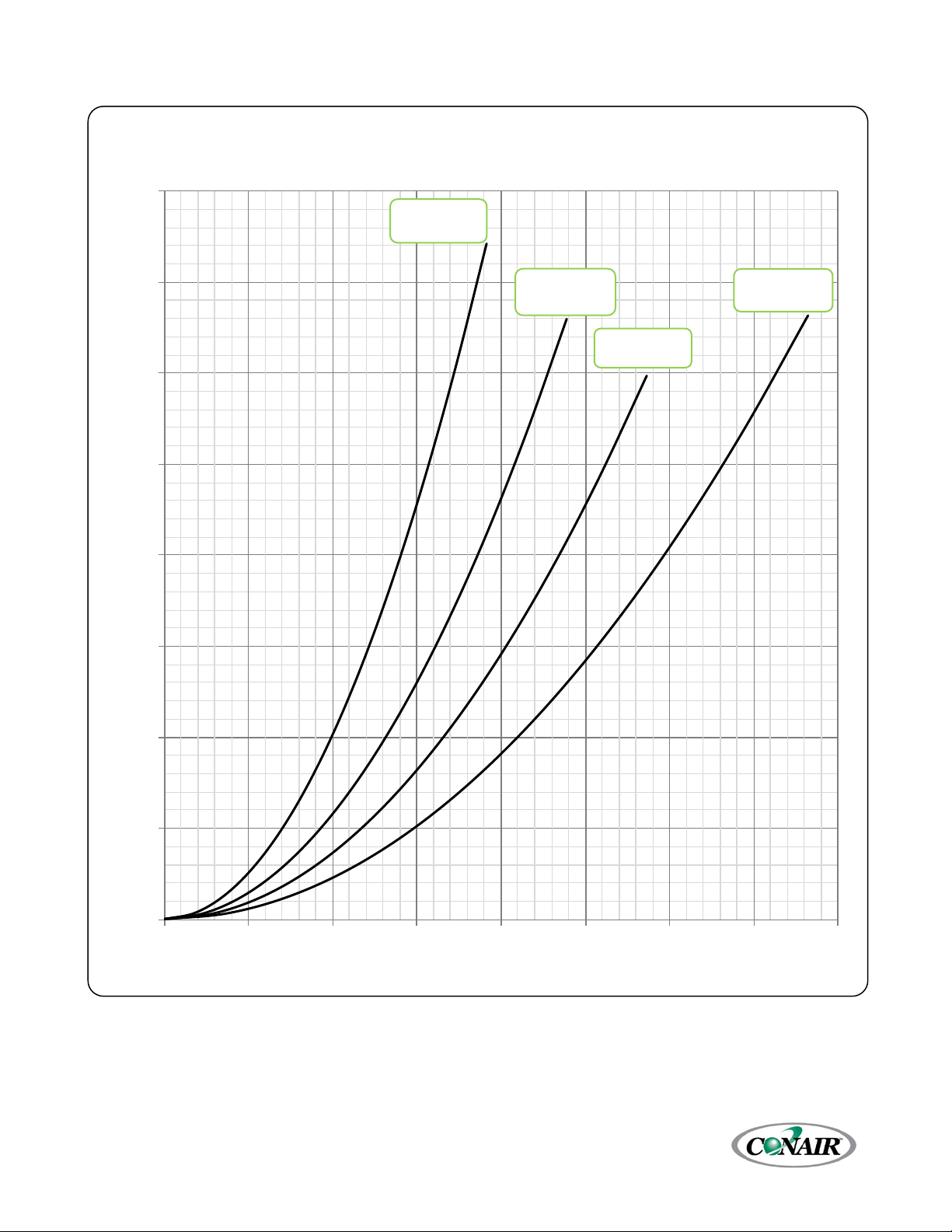
0
5
10
15
20
25
30
35
40
0 50 100 150 200 250 300 350 400
Pressure Loss (psi)
Flow (gpm)
Standard Flow Chiller Coolant Circuit Pressure Drop
(Water at 50°F)
TSEW50S
& T SER50S
TSEW60S
& T SER60S
TSEW80S
& T SER80S
TSEW40S
& T SER40S
ESEW-060S
ESER-060S
Figure 2 – Standard Flow Chiller Coolant Circuit Pressure Drop (40 through 80 Ton Single-Circuit Chillers)
ESEW-040S
ESER-040S
ESEW-050S
ESER-050S
ESEW-080S
ESER-080S
Corporate Office: 724.584.5500 Instant Access 24/7 (Parts and Service): 800.458.1960 Parts and Service: 814.437.6861
12
Page 22
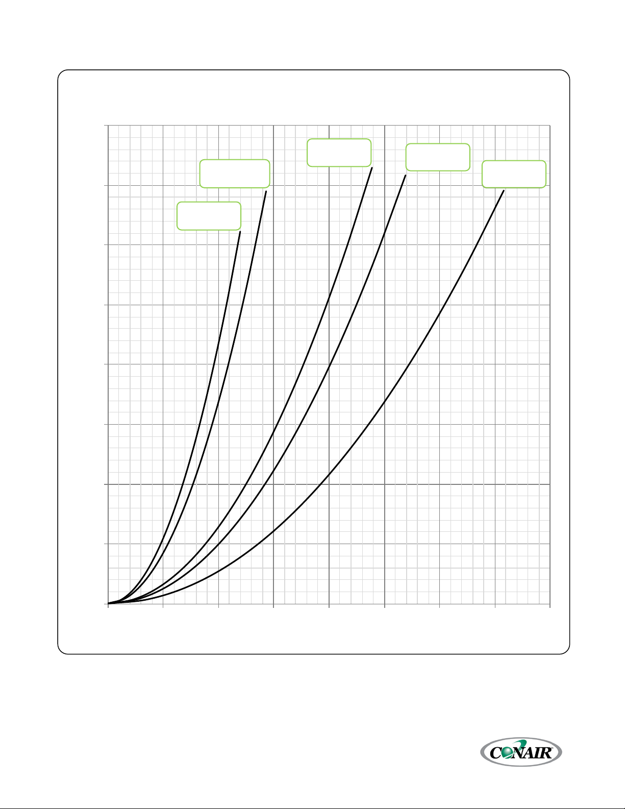
0
5
10
15
20
25
30
35
40
0 40 80 120 160 200 240 280 320
Pressure Loss (psi)
Flow (gpm)
Standard Flow Chiller Coolant Circuit Pressure Drop
(Water at 50°F)
TSEW30D
& T SER30D
TSEW40D
& T SER40D
TSEW50D
& T SER50D
TSEW60D
& T SER60D
TSEW20D
& T SER20D
ESEW-060D
Figure 3 – Standard Flow Chiller Coolant Circuit Pressure Drop (20 through 160 ton Dual-Circuit Chillers)
ESEW-040D
ESER-040D
ESEW-030D
ESER-030D
ESEW-020D
ESER-020D
ESEW-050D
ESER-050D
ESER-060D
Corporate Office: 724.584.5500 Instant Access 24/7 (Parts and Service): 800.458.1960 Parts and Service: 814.437.6861
13
Page 23
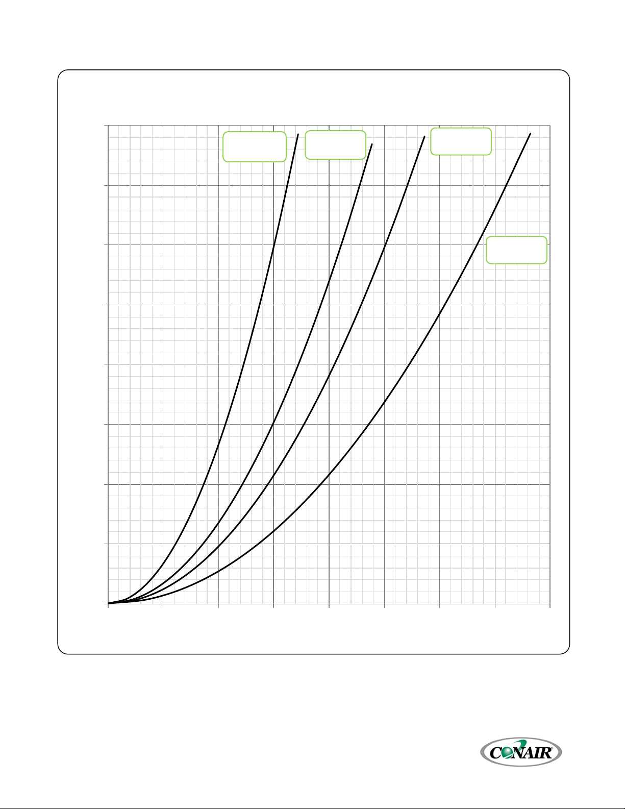
0
5
10
15
20
25
30
35
40
0 100 200 300 400 500 600 700 800
Pressure Loss (psi)
Flow (gpm)
Standard Flow Chiller Coolant Circuit Pressure Drop
(Water at 50°F)
TSEW100D
& T SER100D
TSEW120D
& T SER120D
TSEW160D
& T SER160D
TSEW80D &
TSER80D
Figure 4 – Standard Flow Chiller Coolant Circuit Pressure Drop (80 through 160 ton Dual-Circuit Chillers)
ESEW-080D
ESER-080D
ESEW-0100D
ESER-0100D
ESEW-0120D
ESER-0120D
ESEW-0160D
ESER-0160D
Corporate Office: 724.584.5500 Instant Access 24/7 (Parts and Service): 800.458.1960 Parts and Service: 814.437.6861
14
Page 24
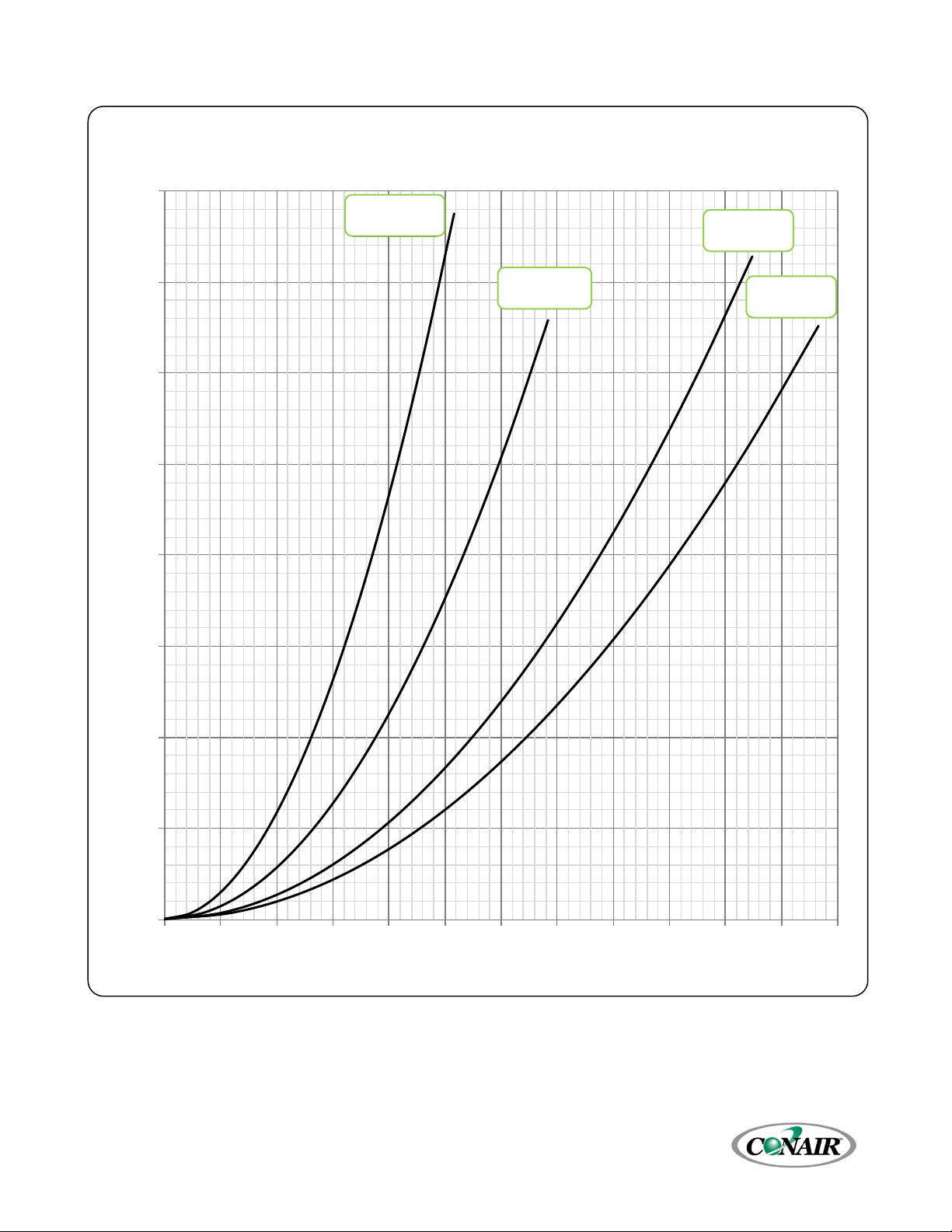
0
5
10
15
20
25
30
35
40
0 20 40 60 80 100 120 140 160 180 200 220 240
Pressure Loss (psi)
Flow (gpm)
High Flow Chiller Coolant Circuit Pressure Drop
(Water at 50°F)
TSEW15S &
TSER15S
TSEW20S &
TSER20S
TSEW25S &
TSER25S
TSEW10S &
TSER10S
Figure 5 – High Flow Chiller Coolant Circuit Pressure Drop (10 through 25 ton Single-Circuit Chillers)
ESEW-010S
ESER-010S
ESEW-015S
ESER-015S
ESEW-020S
ESER-020S
ESEW-025S
ESER-025S
Corporate Office: 724.584.5500 Instant Access 24/7 (Parts and Service): 800.458.1960 Parts and Service: 814.437.6861
15
Page 25

0
5
10
15
20
25
30
35
40
0 50 100 150 200 250 300 350 400 450
Pressure Loss (psi)
Flow (gpm)
High Flow Chiller Coolant Circuit Pressure Drop
(Water at 50°F)
TSEW50S
& T SER50S
TSEW40S
& T SER40S
TSEW30S
& T SER30S
Figure 6 – High Flow Chiller Coolant Pressure Drop (30 through 50 ton Single-Circuit Chillers)
ESEW-030S
ESER-030S
ESEW-040S
ESEW-050S
ESER-050S
ESER-040S
Corporate Office: 724.584.5500 Instant Access 24/7 (Parts and Service): 800.458.1960 Parts and Service: 814.437.6861
16
Page 26
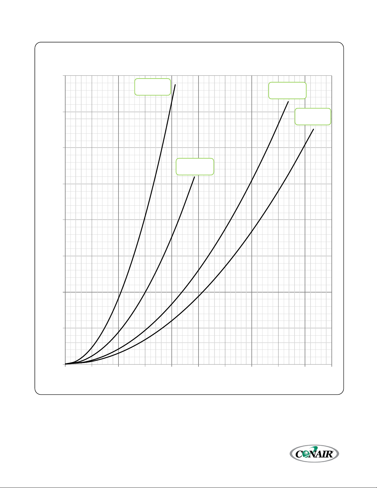
0
5
10
15
20
25
30
35
40
0 50 100 150 200 250 300 350 400 450 500
Pressure Loss (psi)
Flow (gpm)
High Flow Chiller Coolant Circuit Pressure Drop
(Water at 50°F)
TSEW30D
& T SER30D
TSEW40D
& T SER40D
TSEW50D
& T SER50D
TSEW20D
& T SER20D
Figure 7 – High Flow Chiller Coolant Pressure Drop (20 through 50 ton Dual-Circuit Chillers)
ESEW-020D
ESER-020D
ESEW-030D
ESER-030D
ESEW-040D
ESER-040D
ESEW-050D
ESER-050D
Corporate Office: 724.584.5500 Instant Access 24/7 (Parts and Service): 800.458.1960 Parts and Service: 814.437.6861
17
Page 27
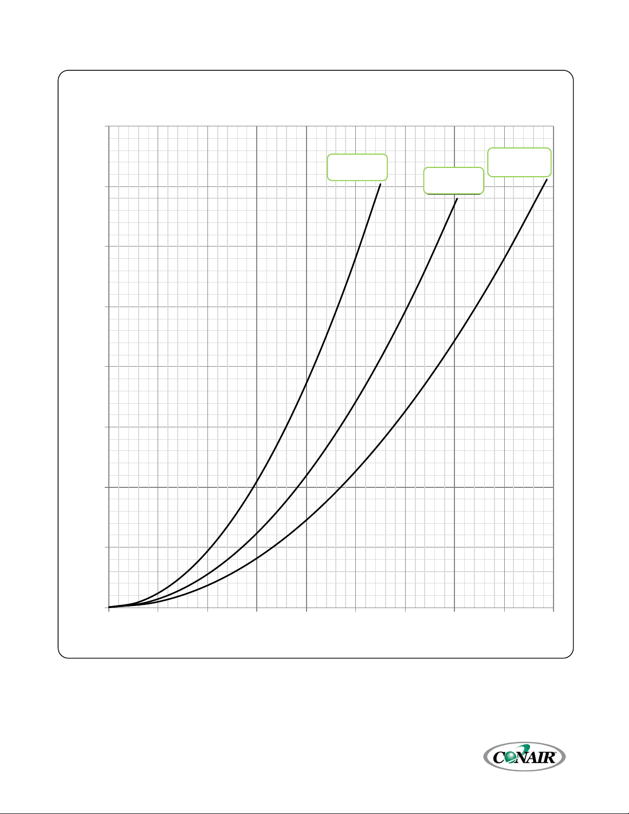
0
5
10
15
20
25
30
35
40
0 100 200 300 400 500 600 700 800 900
Pressure Loss (psi)
Flow (gpm)
High Flow Chiller Coolant Circuit Pressure Drop
(Water at 50°F)
TSEW100D
& T SER100D
TSEW80D
& T SER80D
TSEW60D
& T SER60D
ESER-060D
ESER-080D
Figure 8 – High Flow Chiller Coolant Pressure Drop (60 through 100 ton Dual-Circuit Chillers)
ESEW-060D
ESEW-080D
ESEW-0100D
ESER-0100D
Corporate Office: 724.584.5500 Instant Access 24/7 (Parts and Service): 800.458.1960 Parts and Service: 814.437.6861
18
Page 28
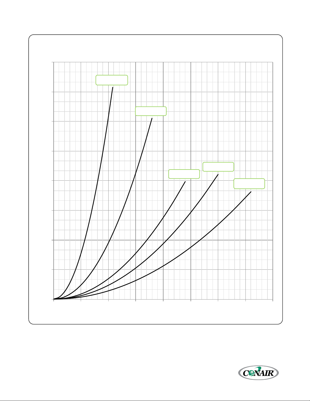
0
3
6
9
12
15
18
21
24
0 25 50 75 100 125 150 175 200
Pressure Loss (psi)
Flow (gpm)
Condenser Water Circuit Pressure Drop
(Water at 85°F with Condenser Water Regulating Valve 100% Open)
TSEW10S
TSEW15S
TSEW20S
TSEW25S
TSEW30S
Figure 9 – Condenser Water Circuit Pressure Drop (10 through 30 ton Single-Circuit Chillers)
ESEW-010S
ESEW-015S
ESEW-020S
ESEW-025S
ESEW-030S
Corporate Office: 724.584.5500 Instant Access 24/7 (Parts and Service): 800.458.1960 Parts and Service: 814.437.6861
19
Page 29
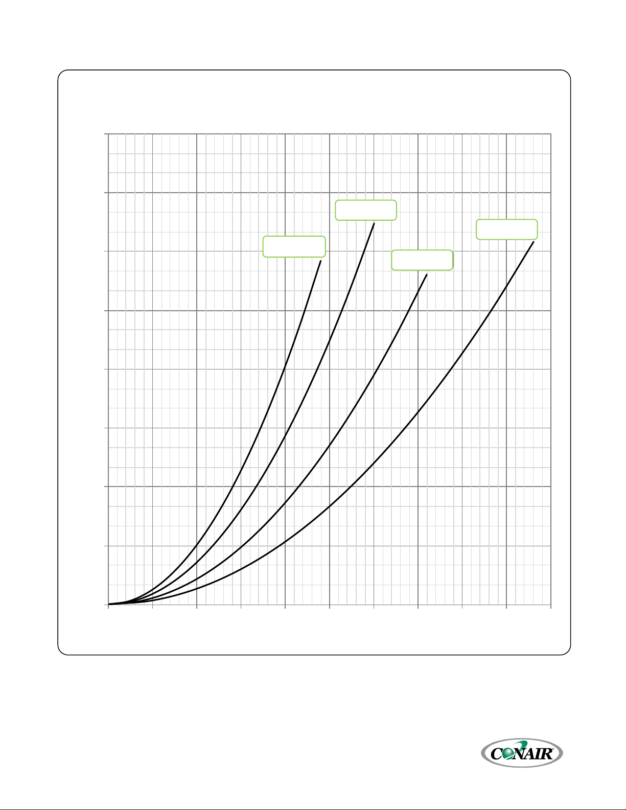
0
3
6
9
12
15
18
21
24
0 50 100 150 200 250 300 350 400 450 500
Pressure Loss (psi)
Flow (gpm)
Condenser Water Cicuit Pressure Drop
(Water at 85°F with Condenser Water Regulating Valve 100% Open)
TSEW40S
TSEW50S
TSEW60S
TSEW80S
Figure 10 – Condenser Water Circuit Pressure Drop (40 through 80 ton Single-Circuit Chillers)
ESEW-050S
ESEW-040S
ESEW-060S
ESEW-080S
Corporate Office: 724.584.5500 Instant Access 24/7 (Parts and Service): 800.458.1960 Parts and Service: 814.437.6861
20
Page 30

0
3
6
9
12
15
18
21
24
0 50 100 150 200 250 300 350 400
Pressure Loss (psi)
Flow (gpm)
Condenser Water Circuit Pressure Drop
(Water at 85°F with Condenser Water Regulating Valve 100% Open)
TSEW20D
TSEW30D
TSEW40D
TSEW50D
TSEW60D
Figure 11 – Condenser Water Circuit Pressure Drop (20 through 60 ton Dual-Circuit Chillers)
ESEW-030D
ESEW-020D
ESEW-040D
ESEW-050D
ESEW-060D
Corporate Office: 724.584.5500 Instant Access 24/7 (Parts and Service): 800.458.1960 Parts and Service: 814.437.6861
21
Page 31

0
3
6
9
12
15
18
21
24
0 100 200 300 400 500 600 700 800 900 1000
Pressure Loss (psi)
Flow (gpm)
Condenser Water Circuit Pressure Drop
(Water at 85°F with Condenser Water Regulating valve 100% Open)
TSEW80D
TSEW100D
TSEW120D
TSEW160D
Figure 12 – Condenser Water Circuit Pressure Drop (80 through 160 ton Dual-Circuit Chillers)
ESEW-080D
ESEW-0100D
ESEW-0120D
ESEW-0160D
Corporate Office: 724.584.5500 Instant Access 24/7 (Parts and Service): 800.458.1960 Parts and Service: 814.437.6861
22
Page 32

Installation - Remote AirCooled Condenser
The remote condenser usually ships separately and
from a different location than the chiller.
Location
Chillers with a remote air-cooled condenser use a
separate remote air-cooled condenser. The
condenser is for outdoor use. A primary concern
when designing your unit was serviceability;
therefore, the condenser should be located in an
accessible area. Install the unit on a firm, level base
no closer than their width from walls or other
condensers. Avoid locations near exhaust fans,
plumbing vents, flues, or chimneys. Fasten the
mounting legs at their base to the steel or concrete
of the supporting structure. For units mounted on a
roof structure, the steel support base holding the
condenser should be elevated above the roof and
attached to the building.
Avoid areas that can create a “micro-climate” such as
an alcove with east, north, and west walls that can be
significantly warmer than surrounding areas. The
condenser needs to have unrestricted airways so it
can easily move cool air in and heated air away.
Consider locating the condenser where fan noise
and vibration transmission into nearby workspaces is
unlikely.
Allow a minimum of the width of the remote
condenser in clearance between the remote
condenser and any walls or obstructions. For
installations with multiple condensers, allow a
minimum of the width of the largest remote
condenser between condensers.
Corporate Office: 724.584.5500 Instant Access 24/7 (Parts and Service): 800.458.1960 Parts and Service: 814.437.6861
23
Page 33

Mounted Legs and Lifting (10 ton Single-Circuit and 20-ton Dual-Circuit Units)
The unit ships on its side with the legs removed to reduce shipping dimensions and provide more protection to
the coil from possible damaged caused by impact loading over rough roads and transit conditions. Follow the
below for mounting of the legs and lifting into position.
Use only qualified persons using the proper equipment when lifting and positioning the condenser. Lifting
brackets or holes are at the corners for attaching lifting slings. Use spreader bars when lifting to apply the lifting
force vertically.
Corporate Office: 724.584.5500 Instant Access 24/7 (Parts and Service): 800.458.1960 Parts and Service: 814.437.6861
24
Page 34

Mounted Legs and Lifting (all except 10 ton Single-Circuit and 20-ton Dual-Circuit Units)
The unit ships on its side with the legs removed to reduce shipping dimensions and provide more protection to
the coil from possible damaged caused by impact loading over rough roads and transit conditions. Follow the
below for mounting of the legs and lifting into position.
Use only qualified persons using the proper equipment when lifting and positioning the condenser. Lifting
brackets or holes are at the corners for attaching lifting slings. Use spreader bars when lifting to apply the lifting
force vertically.
Corporate Office: 724.584.5500 Instant Access 24/7 (Parts and Service): 800.458.1960 Parts and Service: 814.437.6861
25
Page 35

Note: Use refrigerant grade copper tubing ASTM
ODS or smaller.
Note: Do not use soft solders. For copper-to-
WARNING: The POE oil contained within the
tubing.
Interconnecting Refrigerant Piping
The chiller and remote condenser ship with a
nitrogen holding charge. Evacuation of this charge is
required before charging with refrigerant. The chiller
is for use only with the air-cooled condenser
provided with the unit. The following section covers
the required piping between the chiller and the
provided air-cooled condenser.
The chiller may consist of multiple evaporators,
compressors, liquid line solenoid valves, expansion
valves, sight glasses, filter driers, and receivers. The
discharge and liquid lines leaving the chiller have
caps. These line sizes do not necessarily reflect the
actual line sizes required for the piping between the
chiller and the air-cooled condenser. The installing
contractor need only provide the interconnecting
piping between the chiller and the air-cooled
condenser.
Refrigerant piping size and piping design have a
significant effect on system performance and
reliability. Refer to the Refrigeration Line Sizing
section of this manual to ensure the refrigerant
piping and runs are proper. All piping should
conform to the applicable local and state codes.
B280 only and isolate the refrigeration lines
from building structures to prevent transfer of
vibration. All copper tubing must have a pressure
rating suitable for R-410A: tubing that is ¾” OD
or larger must be Type K rigid tubing. ACR
annealed tubing coil may be used for sizes ⅝”
Do not use a saw to remove end caps. This might
allow copper chips to contaminate the system. Use a
tube cutter or heat to remove the caps. When
sweating copper joints it is important to evacuate all
refrigerant present if any and flow dry nitrogen
through the system. This prevents the formation of
toxic gases, corrosive acids, and the formation of
scale within the copper tube.
copper joints use a copper-phosphorus braze
alloy (BCuP per the American Welding Society)
with 5% (BCuP-3) to 15% (BCuP-5) silver
content. Only use a high silver content brazing
alloy (BAg per AWS) for copper-to-brass or
copper-to-steel joints such as a 45% (BAg-5)
silver content. Only use oxy-acetylene brazing.
compressor is hygroscopic and has the ability to
absorb water vapor from the atmosphere. Take
necessary steps to prevent an open system from
exposure to the atmosphere for extended periods
while installing the interconnecting refrigerant
Refrigeration Piping Design
The system is configurable in any of the
arrangements as shown in Figure 13, Figure 14, and
Figure 15. The configuration and its associated
elevation, along with the total distance between the
chiller and the air-cooled condenser are important
factors in determining the liquid line and discharge
line sizes. This will also affect the field refrigerant
charges. Consequently, it is important to adhere to
certain physical limitations to ensure the system
operates as designed.
General design considerations are:
1. The total distance between the chiller and the
air-cooled condenser must not exceed 200
actual feet (70.0 m) or 300 equivalent feet
(91.4 m). Keep the distance as short as possible.
2. Liquid line risers must not exceed 15 feet (4.6 m)
in height from the condenser liquid line
connection.
3. Discharge line risers cannot exceed an elevation
difference greater than 100 actual feet (30.5 m)
without a minimum of 2% efficiency decrease.
4. To form a proper liquid seal at the condenser,
immediately drop at least 15 inches (38.1 cm)
down from the liquid outlet before routing the
piping to the chiller. Make the drop leg before
any bends or angles connecting to the
remainder of the liquid connection piping.
Corporate Office: 724.584.5500 Instant Access 24/7 (Parts and Service): 800.458.1960 Parts and Service: 814.437.6861
26
Page 36

Condenser Width
To be same as
condenser width
Chiller
15" minimum at liquid
exit from condenser.
W W
Chiller
Locate condenser so
condenser liquid turns
down right away.
Figure 13 – Condenser Located with No Elevation Difference
Figure 14 – Condenser Located above Chiller Unit
Corporate Office: 724.584.5500 Instant Access 24/7 (Parts and Service): 800.458.1960 Parts and Service: 814.437.6861
27
Page 37

Note: Liquid line sizing for each chiller capacity is in Table 7. These line sizes are listed per circuit and apply where
ASHRAE Refrigeration Handbook or other suitable design guide.
Note: When calculating the equivalent length, do
piping must be considered.
Chiller
10' MAX
Figure 15 - Condenser Located Below Chiller Unit
leaving water temperature (LWT) is 40°F or higher. For applications where the LWT is below 40°F, size lines using the
Determining Equivalent Line Length
To determine the appropriate size for field installed
liquid and discharge lines, it is first necessary to
establish the equivalent length of pipe for each line.
The equivalent length is the approximate friction loss
from the combined linear run of pipe and the
equivalent feet of elbows, valves, and other
components in the refrigeration piping. The sum
total is the equivalent length of pipe that would have
the same pressure loss. See the ASHRAE
Refrigeration Handbook for more information.
Follow these steps when calculating line size:
1. Start with an initial approximation of equivalent
length by assuming that the equivalent length of
pipe is 1.5 times the actual pipe length.
2. Determine approximate line sizes by referring to
Table 7 for liquid lines, Table 8 and Table 9 for
the discharge lines.
3. Check the line size by calculating the actual
equivalent length using the equivalent lengths
as shown in Table 6.
not include piping of the chiller unit. Only field
Corporate Office: 724.584.5500 Instant Access 24/7 (Parts and Service): 800.458.1960 Parts and Service: 814.437.6861
28
Page 38

Elbow
Standard
Elbow 90°
Radius
⅞
2.0
1.4
3.2
0.9
1.6
1⅛
2.6
1.7
4.1
1.3
2.1
1⅝
2⅛
5.0
3.3
8.2
2.6
4.5
2⅝
6.0
4.1
10.0
3.2
5.2
3⅛
7.5
5.0
12.0
4.0
6.4
4⅛
10.0
6.7
17.0
5.2
8.5
Table 6 – Equivalent Lengths of Fittings
Line
Size
OD
inches
1⅜ 3.3 2.3 5.6 1.7 3.0
3⅝ 9.0 5.9 15.0 4.7 7.3
Equivalent Lengths of Refrigerant Pipe (feet)
90°
4.0 2.6 6.3 2.1 3.4
Long
Elbow 90°
Street
Elbow 45°
Standard
Elbow 45°
Street
Liquid Line Sizing
The liquid line diameter should be as small as
possible while maintaining acceptable pressure drop.
This is necessary to minimize refrigerant charge. The
total length between the chiller unit and the aircooled condenser must not exceed 200 actual feet
(70.0 m) or 300 equivalent feet (91.4 m).
Liquid line risers in the system will require an
additional 0.5 psig pressure drop per foot of vertical
rise. When it is necessary to have a liquid line riser,
make the vertical run immediately after the
condenser before any additional restrictions. The
liquid line risers must not exceed 10 feet (3.0 m) in
height from the condenser liquid line connection
(see Figure 15). The liquid line does not require
pitching. Install a pressure tap valve at the condenser
to facilitate measuring pressure for service.
Liquid lines do not typically require insulation.
However, if exposing the lines to solar heat gain or
temperatures exceeding 110 °F (43.3°C), there is a
negative effect on sub-cooling. In these situations,
insulate the liquid lines.
Corporate Office: 724.584.5500 Instant Access 24/7 (Parts and Service): 800.458.1960 Parts and Service: 814.437.6861
29
Page 39

10 Ton Circuit (R410A)
15 Ton Circuit (R410A)
Liquid Line Size (Inch OD)
Liquid Line Size (Inch OD)
Horizontal
Downflow
Horizontal
Downflow
25 ⅝ ⅝ ⅝ ¾
25 ⅞ ⅞ ⅞ ⅞
50 ⅝ ⅝ ¾ ¾
50 ⅞ ⅞ ⅞ ⅞
75 ⅝ ⅝ ¾ ¾
75 ⅞ ⅞ ⅞ ⅞
100 ⅝ ¾ ¾ ¾
100 ⅞ ⅞ ⅞ 1⅛
125 ¾ ¾ ¾ ⅞
125 ⅞ ⅞ ⅞ 1⅛
150 ¾ ¾ ¾ ⅞
150 ⅞ ⅞ ⅞ 1⅛
175 ¾ ¾ ¾ ⅞
175 ⅞ ⅞ ⅞ 1⅛
200 ¾ ¾ ¾ ⅞
200 ⅞ ⅞ ⅞ 1⅛
225 ¾ ¾ ¾ ⅞
225 ⅞ ⅞ ⅞ 1⅜
250 ¾ ¾ ¾ ⅞
250 ⅞ ⅞ ⅞ 1⅜
275 ¾ ¾ ¾ 1⅛
275 ⅞ ⅞ ⅞ 1⅜
300 ⅞ ⅞ ⅞ 1⅛
300 ⅞ ⅞ ⅞ 1⅜
20 Ton Circuit (R410A)
25 Ton Circuit (R410A)
Liquid Line Size (Inch OD)
Liquid Line Size (Inch OD)
Horizontal
Downflow
Horizontal
Downflow
25
25
50 ⅞ ⅞ ⅞ 1⅛
50
1⅛
1⅛
1⅛
1⅛
75 ⅞ ⅞ ⅞ 1⅛
75
1⅛
1⅛
1⅛
1⅛
100 ⅞ ⅞
1⅛
1⅛
100
1⅛
1⅛
1⅛
1⅜
125 ⅞ ⅞
1⅛
1⅛
125
1⅛
1⅛
1⅛
1⅜
150 ⅞ 1⅛
1⅛
1⅜
150
1⅛
1⅛
1⅛
1⅜
175 ⅞ 1⅛
1⅛
1⅜
175
1⅛
1⅛
1⅛
1⅜
200
1⅛
1⅛
1⅛
1⅜
200
1⅛
1⅛
1⅛
1⅜
225
1⅛
1⅛
1⅛
1⅜
225
1⅛
1⅛
1⅜
1⅜
250
1⅛
1⅛
1⅛
1⅜
250
1⅛
1⅛
1⅜
1⅜
275
1⅛
1⅛
1⅛
1⅜
275
1⅛
1⅛
1⅜
1⅜
300
1⅛
1⅛
1⅛
1⅜
300
1⅛
1⅛
1⅜
1⅜
Table 7 – Liquid Line Sizes for R410A
Total
Equivalent
Length (ft)
Total
Equivalent
Length (ft)
or
or
⅞ ⅞ ⅞ 1⅛
Upflow
1 to 5 ft
Upflow
1 to 5 ft
Upflow
6 to 10 ft
Upflow
6 to 10 ft
Upflow
11 to 15 ft
Upflow
11 to 15 ft
Total
Equivalent
Length (ft)
Total
Equivalent
Length (ft)
or
or
1⅛ 1⅛ 1⅛ 1⅛
Upflow
1 to 5 ft
Upflow
1 to 5 ft
Upflow
6 to 10 ft
Upflow
6 to 10 ft
Upflow
11 to 15 ft
Upflow
11 to 15 ft
Corporate Office: 724.584.5500 Instant Access 24/7 (Parts and Service): 800.458.1960 Parts and Service: 814.437.6861
30
Page 40

30 Ton Circuit (R410A)
40 Ton Circuit (R410A)
Liquid Line Size (Inch OD)
Liquid Line Size (Inch OD)
Horizontal
Downflow
Horizontal
Downflow
25
1⅛
1⅛
1⅛
1⅛
25
1⅛
1⅛
1⅛
1⅛
50
1⅛
1⅛
1⅛
1⅛
50
1⅛
1⅛
1⅛
1⅜
75
1⅛
1⅛
1⅛
1⅛
75
1⅛
1⅛
1⅛
1⅜
100
1⅛
1⅛
1⅛
1⅛
100
1⅛
1⅛
1⅜
1⅜
125
1⅛
1⅛
1⅛
1⅛
125
1⅛
1⅛
1⅜
1⅜
150
1⅛
1⅛
1⅛
1⅛
150
1⅛
1⅜
1⅜
1⅝
175
1⅛
1⅛
1⅛
1⅛
175
1⅛
1⅜
1⅜
1⅝
200
1⅛
1⅛
1⅛
1⅛
200
1⅜
1⅜
1⅜
1⅝
225
1⅛
1⅛
1⅛
1⅛
225
1⅜
1⅜
1⅜
1⅝
250
1⅛
1⅛
1⅛
1⅛
250
1⅜
1⅜
1⅝
2⅛
275
1⅛
1⅛
1⅛
1⅛
275
1⅜
1⅜
1⅝
2⅛
300
1⅛
1⅛
1⅛
1⅜
300
1⅜
1⅜
1⅝
2⅛
50 Ton Circuit (R410A)
60 Ton Circuit (R410A)
Liquid Line Size (Inch OD)
Liquid Line Size (Inch OD)
Horizontal
Downflow
Horizontal
Downflow
25
25
50
1⅛
1⅛
1⅛
1⅜
50
1⅛
1⅛
1⅜
1⅝
75
1⅛
1⅛
1⅜
1⅝
75
1⅛
1⅜
1⅜
1⅝
100
1⅛
1⅛
1⅜
1⅝
100
1⅜
1⅜
1⅜
1⅝
125
1⅛
1⅜
1⅜
1⅝
125
1⅜
1⅜
1⅝
2⅛
150
1⅜
1⅜
1⅜
1⅝
150
1⅜
1⅜
1⅝
2⅛
175
1⅜
1⅜
1⅝
2⅛
175
1⅜
1⅜
1⅝
2⅛
200
1⅜
1⅜
1⅝
2⅛
200
1⅜
1⅝
1⅝
2⅛
225
1⅜
1⅜
1⅝
2⅛
225
1⅜
1⅝
1⅝
2⅛
250
1⅜
1⅜
1⅝
2⅛
250
1⅜
1⅝
1⅝
2⅛
275
1⅜
1⅝
1⅝
2⅛
275
1⅝
1⅝
2⅛
2⅛
300
1⅜
1⅝
1⅝
2⅛
300
1⅝
1⅝
2⅛
2⅛
Table 7 – Liquid Line Sizes for R410A (continued)
Total
Equivalent
Length (ft)
Total
Equivalent
Length (ft)
or
or
1⅛ 1⅛ 1⅛ 1⅜
Upflow
1 to 5 ft
Upflow
1 to 5 ft
Upflow
6 to 10 ft
Upflow
6 to 10 ft
Upflow
11 to 15 ft
Upflow
11 to 15 ft
Total
Equivalent
Length (ft)
Total
Equivalent
Length (ft)
or
or
1⅛ 1⅛ 1⅜ 1⅝
Upflow
1 to 5 ft
Upflow
1 to 5 ft
Upflow
6 to 10 ft
Upflow
6 to 10 ft
Upflow
11 to 15 ft
Upflow
11 to 15 ft
Corporate Office: 724.584.5500 Instant Access 24/7 (Parts and Service): 800.458.1960 Parts and Service: 814.437.6861
31
Page 41

80 Ton Circuit (R410A)
Liquid Line Size (Inch OD)
Horizontal
Downflow
Upflow
ft
25
1⅛
1⅜
1⅜
1⅝
50
1⅛
1⅜
1⅜
1⅝
75
1⅜
1⅜
1⅝
2⅛
100
1⅜
1⅜
1⅝
2⅛
125
1⅜
1⅝
1⅝
2⅛
150
1⅜
1⅝
1⅝
2⅛
175
1⅝
1⅝
2⅛
2⅛
200
1⅝
1⅝
2⅛
2⅛
225
1⅝
1⅝
2⅛
2⅝
250
1⅝
1⅝
2⅛
2⅝
275
1⅝
2⅛
2⅛
2⅝
300
1⅝
2⅛
2⅛
2⅝
FROM
CHILLER
15'
TO
CONDENSER
TRAP &
REVERSE
TRAP
(4 LR STREET ELS)
REVERSE
TRAP
(3 LR STREET ELS)
REVERSE
TRAP
(3 LR STREET ELS)
VERTICLE UPFLOW
DISCHARGE RISER
Table 7 – Liquid Line Sizes for R410A (continued)
Total
Equivalent
Length
(ft)
or
Upflow
1 to 5 ft
Upflow
6 to 10 ft
11 to 15
Figure 16 – Vertical Riser Traps
Discharge (Hot Gas) Line Sizing
The discharge line sizes depend on the velocity
needed to obtain sufficient oil return. It is very
important to minimize line length and restrictions to
reduce pressure drop and maximize capacity.
Upflow hot gas risers need to have a trap at the
bottom and reverse trap at the top. In addition, a
trap and reverse trap arrangement needs to be
spaced every 15 feet (4.6 m) in the rise for oil
management (see Figure 16).
The discharge lines should pitch downward, in the
direction of the hot gas flow, at the rate of ½ inch
per each 10 foot (1.27 cm per 3.05 m) of horizontal
run. If the chiller unit is below the condenser, loop
the discharge line to at least 1 inch (2.54 cm) above
the top of the condenser. Install a pressure tap valve
at the condenser to facilitate measuring pressure for
service. Take careful consideration in the design of
the discharge gas riser.
Corporate Office: 724.584.5500 Instant Access 24/7 (Parts and Service): 800.458.1960 Parts and Service: 814.437.6861
All chillers have unloading capabilities. The chiller
uses tandem compressors with one circuit per
tandem set. Unloading will cycle off one of the
compressors. This is not enough to cause problems
with oil return from the remote condenser. Check
the oil-level sight glass in the compressor if there is
a concern there may be oil in the piping.
On chillers equipment with the optional hot gas
bypass capacity control the gas in the upflow
discharge lines may have problems moving the oil
against gravity when completely unloaded. For those
systems only, see Figure 17 and Table 9 for double
riser constructions.
32
Page 42

Note: Discharge line sizing shown in Table 8 and Table 9 are listed per circuit and applies where leaving water
Handbook or other suitable design guide.
25
50
75
100
125
150
175
200
225
250
275
300
10 ⅞ ⅞ ⅞ ⅞ ⅞ ⅞ ⅞ 1⅛
1⅛
1⅛
1⅛
1⅛
15 ⅞ ⅞
1⅛
1⅛
1⅛
1⅛
1⅛
1⅛
1⅛
1⅛
1⅜
1⅜
20 ⅞ 1⅛
1⅛
1⅜
1⅜
1⅜
1⅜
1⅜
1⅜
1⅜
1⅝
1⅝
25
1⅛
1⅛
1⅛
1⅛
1⅜
1⅜
1⅜
1⅜
1⅜
1⅜
1⅝
1⅝
30
1⅛
1⅛
1⅛
1⅜
1⅜
1⅜
1⅜
1⅜
1⅜
1⅝
1⅝
1⅝
40
1⅝
1⅝
1⅝
1⅝
1⅝
1⅝
2⅛
2⅛
2⅛
2⅛
2⅛
2⅛
50
1⅝
1⅝
1⅝
1⅝
1⅝
2⅛
2⅛
2⅛
2⅛
2⅛
2⅛
2⅛
60
1⅝
1⅝
1⅝
2⅛
2⅛
2⅛
2⅛
2⅛
2⅛
2⅛
2⅛
2⅛
80
1⅝
1⅝
2⅛
2⅛
2⅛
2⅛
2⅛
2⅛
2⅝
2⅝
2⅝
2⅝
A
B
REDUCING
TEE
FROM
CHILLER
PITCH TO
CONDENSER
45 DEGREE
STREET ELBOWS
90 DEGREE
STREET ELBOWS
Figure 17 - Double Discharge Riser
temperature (LWT) is 40°F or higher. For applications where LWT is below 40°F, size lines using the ASHRAE Refrigeration
Table 8 – Discharge Line Sizes for Chiller (inches OD)
Circuit
Tons
Total Equivalent Length (ft)
Corporate Office: 724.584.5500 Instant Access 24/7 (Parts and Service): 800.458.1960 Parts and Service: 814.437.6861
33
Page 43

25
50
75
100
125
150
175
200
225
250
275
300
A - ⅜
A - ⅜
A - ⅜
A - ⅜
A - ⅜
A - ⅜
A - ⅜
A - ⅜
A - ⅜
A - ⅜
A - ⅜
A - ⅜
B - ¾
B - ¾
B - ¾
B - ¾
B - ¾
B - ¾
B - ¾
B - ⅞
B - ⅞
B - ⅞
B - ⅞
B - ⅞
A - ⅜
A - ⅜
A - ⅜
A - ⅜
A - ⅜
A - ⅜
A - ⅜
A - ⅜
A - ⅜
A - ⅜
A - ½
A - ½
B - ¾
B - ¾
B - ⅞
B - ⅞
B - ⅞
B - ⅞
B - ⅞
B - ⅞
B - ⅞
B - ⅞
B - 1⅛
B - 1⅛
A - ⅜
A - ⅜
A - ⅜
A - ½
A - ½
A - ½
A - ½
A - ½
A - ½
A - ½
A - ⅝
A - ⅝
B - ¾
B - ⅞
B - ⅞
B - 1⅛
B - 1⅛
B - 1⅛
B - 1⅛
B - 1⅛
B - 1⅛
B - 1⅛
B - 1⅜
B - 1⅜
A - ⅜
A - ⅜
A - ⅜
A - ½
A - ½
A - ½
A - ½
A - ½
A - ½
A - ½
A - ⅝
A - ⅝
B - ⅞
B - ⅞
B - ⅞
B - 1⅛
B - 1⅛
B - 1⅛
B - 1⅛
B - 1⅛
B - 1⅛
B - 1⅛
B - 1⅜
B - 1⅜
A - ½
A - ½
A - ½
A - ¾
A - ¾
A - ¾
A - ¾
A - ¾
A - ¾
A - ¾
A - ¾
A - ¾
B - ⅞
B - ⅞
B - ⅞
B - 1⅛
B - 1⅛
B - 1⅛
B - 1⅛
B - 1⅛
B - 1⅛
B - 1⅜
B - 1⅜
B - 1⅜
A - ¾
A - ¾
A - ¾
A - ¾
A - ¾
A - ¾
A - ¾
A - ¾
A - ¾
A - ¾
A - ¾
A - ¾
B - 1⅜
B - 1⅜
B - 1⅜
B - 1⅜
B - 1⅜
B - 1⅜
B - 1⅝
B - 1⅝
B - 1⅝
B - 1⅝
B - 1⅝
B - 1⅝
A - ¾
A - ¾
A - ¾
A - ¾
A - ¾
A - ¾
A - ¾
A - ¾
A - ¾
A - ¾
A - ¾
A - ¾
B - 1⅜
B - 1⅜
B - 1⅜
B - 1⅜
B - 1⅜
B - 1⅝
B - 1⅝
B - 1⅝
B - 1⅝
B - 1⅝
B - 1⅝
B - 1⅝
A - ¾
A - ¾
A - ⅞
A - ⅞
A - ⅞
A - ⅞
A - ⅞
A - ⅞
A - ⅞
A - ⅞
A - ⅞
A - ⅞
B - 1⅜
B - 1⅜
B - 1⅝
B - 1⅝
B - 1⅝
B - 1⅝
B - 1⅝
B - 1⅝
B - 1⅝
B - 1⅝
B - 1⅝
B - 1⅝
A - ¾
A - ¾
A - ⅞
A - ⅞
A - ⅞
A - ⅞
A - ⅞
A - ⅞
A - ⅞
A - ⅞
A - ⅞
A - ⅞
B - 1⅜
B - 1⅜
B - 1⅝
B - 1⅝
B - 1⅝
B - 1⅝
B - 1⅝
B - 1⅝
B - 2⅛
B - 2⅛
B - 2⅛
B - 2⅛
Refrigeration Circuit Capacity (tons)
10
15
20
25
30
40
50
60
80
Single-Circuit Chillers
15.3
22.2
30.2
37.2
44.3
59.4
79.6
109.0
136.1
Dual-Circuit Chillers
17.3
24.7
30.2
37.2
43.8
59.4
79.6
108.5
136.1
Line Size OD (inches)
⅜ ½ ⅝ ¾ ⅞
1⅛
1⅜
1⅝
2⅛
2⅝
Discharge Line
0.4
0.7
1.1
1.6
2.2
3.6
5.6
7.9
13.9
21.4
Liquid Line
3.7
6.8
11.0
16.4
22.8
36.7
57.4
81.2
142.1
219.5
Table 9 - Upflow Discharge Line Sizes for R410A (inches OD)
Circuit
Tons
10
15
20
25
30
40
50
60
80
Total Equivalent Length (ft)
Calculating System Refrigerant and Oil Charge
To determine the approximate charge, first refer to Table 10 and establish the required charge for the condenser
and chiller. Values given in Table 10 are per circuit. Then refer to Table 11 to determine the charge required for
the field-installed piping per circuit. The approximate charge per circuit is therefore the sum of the values from
Table 10 and Table 11.
Table 10 – Combined Chiller and Remote Condenser Summer Refrigerant Charge
Refrigerant Charge (Lbs. of R-410A)
Table 11 - Field Piping R-410A Refrigerant Charge per 100 Feet of Run (Lbs.)
Corporate Office: 724.584.5500 Instant Access 24/7 (Parts and Service): 800.458.1960 Parts and Service: 814.437.6861
34
Page 44

Stage
Number
Number of Fan Stages
1 2 3 4 5
6
Max Speed
410
410
410
410
410
410
Min Speed
320
320
320
320
320
320
Fan On
365
365
365
365
365
Fan Off
330
330
330
330
330
Fan On
375
375
375
375
Fan Off
340
340
340
340
Fan On
385
385
385
Fan Off
350
350
350
Fan On
395
395
Fan Off
360
360
405
370
Oil Charge Determination
The chiller is factory charged with the amount of oil
required by the chiller only and not the total system.
The amount of oil required is dependent upon the
amount of refrigerant added to the system for the
field-installed piping. Use the following to determine
the amount of oil needed for the system.
Pints of Oil = Pounds of refrigerant added to the
system / 100
Check the oil level after the chiller has run for 15
minutes.
Setting Condenser Fan Controls
Depending on the number of condenser fans
present there will be different fan cycling pressure
control setting requirements. It is important that
these settings be correct in order to maintain proper
capacity control and operation of the system. Each
refrigerant circuit has a separate head-pressure
control circuit. Refer to Table 12 for the proper
pressure settings.
Table 12 - Condenser Fan Pressure Settings (psig)
Setting
Stage 1
Stage 2
Stage 3
Stage 4
Stage 5
Stage 6
Note: Dual circuit condensers have two separate head-pressure
controls circuits.
Corporate Office: 724.584.5500 Instant Access 24/7 (Parts and Service): 800.458.1960 Parts and Service: 814.437.6861
35
Page 45

WARNING: This equipment contains hazardous
WARNING: This equipment contains refrigerant
property damage.
WARNING: This equipment may contain fan
in place.
WARNING: The exposed surfaces of motors,
if touched with unprotected hands.
CAUTION: Disconnect and lock out incoming
opening access panels for repair or maintenance.
CAUTION: Wear eye protection when installing,
CAUTION: Wear protective gloves when
or fluid leaks.
CAUTION: Ground the unit properly in
CAUTION: The unit requires the main power to
Installation - Electrical
All wiring must comply with local codes and the
National Electric Code. Minimum Circuit Amps (MCA)
and other unit electrical data are on the unit
nameplate. A unit specific electrical schematic ships
with the unit. Measure each leg of the main power
supply voltage at the main power source. Voltage
must be within the voltage utilization range given on
the drawings included with the unit. If the measured
voltage on any leg is not within the specified range,
notify the supplier and correct before operating the
unit. Voltage imbalance must not exceed 2%.
Excessive voltage imbalance between the phases of a
three-phase system can cause motors to overheat
and eventually fail. Voltage imbalance is determined
using the following calculations:
% Imbalance = (Vavg – Vx) x 100 / Vavg
Vavg = (V1 + V2 + V3) / 3
Vx = phase with greatest difference from Vavg
There is a terminal block for main power connection
to the main power source. The main power source
should be connected to the terminal block through
an appropriate disconnect switch. There is a separate
lug in the main control panel for grounding the unit.
Check the electrical phase sequence at installation
and prior to start-up. Operation of the compressor
with incorrect electrical phase sequencing will result
in mechanical damage to the compressors. Check
the phasing with a phase sequence meter prior to
applying power. The proper sequence should read
“ABC” on the meter. If the meter reads “CBA”, open
the main power disconnect and switch two line leads
on the line power terminal blocks (or the unit
mounted disconnect). Do not interchange any load
leads that are from the unit contactors or the motor
terminals.
voltages that can cause severe injury or death.
under pressure. Accidental release of refrigerant
under pressure can cause personal injury and or
blades or other sharp edges. Make sure all fan
guards and other protective shields are securely
refrigerant piping, and other fluid circuit
components can be very hot and can cause burns
power before installing, servicing, or
maintaining the equipment. Connecting power to
the main terminal block energizes the entire
electric circuitry of the unit. A power supply
provides 24 VDC control power. Electric power at
the main disconnect should be shut off before
maintaining, or repairing the equipment to
protect against any sparks, debris, or fluid leaks.
installing, maintaining, or repairing the
equipment to protect against any sparks, debris,
compliance with local and national codes.
remain connected during off-hours to energize
the compressor’s crankcase heater. Disconnect
main power only when servicing the chiller. The
crankcase heater should remain on when the
compressor is off to ensure liquid refrigerant
does not accumulate in the compressor
crankcase. Connect main power at least 24 hours
prior to initial start-up.
Corporate Office: 724.584.5500 Instant Access 24/7 (Parts and Service): 800.458.1960 Parts and Service: 814.437.6861
36
Page 46

Main Power (3-phase, 60 Hz)
Compressors
Chiller
Allowable
RLA1 LRA
2
Min
Max
(each)
(each)
208
187
253 2 19.0
123
43
60
230
187
253 2 19.0
123
43
70
460
414
508 2 9.7
62
22
35
575
518
632 2 7.4
50
18
25
208
187
253 2 29.5
195
67
110
230
187
253 2 29.5
195
67
110
460
414
508 2 14.7
95
34
50
575
518
632 2 12.2
80
29
45
208
187
253 2 33.3
239
76
125
230
187
253 2 33.3
239
76
125
460
414
508 2 17.9
125
42
60
575
518
632 2 12.8
80
30
45
208
187
253 2 51.3
300
117
175
230
187
253 2 51.3
300
117
175
460
414
508 2 23.1
150
53
80
575
518
632 2 19.9
109
46
70
208
187
253 2 55.8
340
127
200
230
187
253 2 55.8
340
127
200
460
414
508 2 26.9
173
62
100
575
518
632 2 23.7
132
55
80
208
187
253 2 72.4
538
164
250
230
187
253 2 72.4
538
164
250
460
414
508 2 30.8
229
71
110
575
518
632 2 25.0
180
58
90
208
187
253 2 85.3
605
193
300
230
187
253 2 85.3
605
193
300
460
414
508 2 37.8
320
86
125
575
518
632 2 34.6
250
79
125
208
187
253 2 109.6
599
248
400
230
187
253 2 109.6
599
248
400
460
414
508 2 54.5
310
124
200
575
518
632 2 49.4
239
112
175
208
187
253 2 N/A
N/A
N/A
N/A
230
187
253 2 N/A
N/A
N/A
N/A
460
414
508 2 73.0
368
165
250
575
518
632 2 N/A
N/A
N/A
N/A
Table 13 – ESEW & ESER Single-Circuit Chiller Electrical Data (60 Hz)
Model
ESEW-010S
& ESER-010S
ESEW-015S
& ESER-015S
ESEW-020S
& ESER-020S
ESEW-025S
& ESER-025S
ESEW-030S
& ESER-030S
ESEW-040S
& ESER-040S
Rated
Qty
MCA
3
MOPD
4
ESEW-050S
& ESER-050S
ESEW-060S
& ESER-060S
ESEW-080S
& ESER-080S
1
RLA is Rated Load Amps.
2
LRA is Locked Rotor Amps.
3
MCA is Minimum Circuit Amps (for wire sizing), complies with NEC, Section 430-24.
4
MOPD is Maximum Over-current Protection Device, complies with NEC, Section 430-53.
Corporate Office: 724.584.5500 Instant Access 24/7 (Parts and Service): 800.458.1960 Parts and Service: 814.437.6861
37
Page 47

Main Power
(3-phase, 60 Hz)
Process
Pump
Min
Max
(ea)
(ea)
Qty
FLA3 Qty
FLA
3
208
187
253 2 19.0
123 1 16.6 1 5.3
65
80
230
187
253 2 19.0
123 1 15.0 1 4.8
63
80
460
414
508 2 9.7
62 1 7.5 1 2.4
32
40
575
518
632 2 7.4
50 1 6.0 1 1.9
25
30
208
187
253 2 29.5
195 1 16.6 1 5.3
88
110
230
187
253 2 29.5
195 1 15.0 1 4.8
86
110
460
414
508 2 14.7
95 1 7.5 1 2.4
43
50
575
518
632 2 12.2
80 1 6.0 1 1.9
35
45
208
187
253 2 33.3
239 1 16.6 1 5.3
97
125
230
187
253 2 33.3
239 1 15.0 1 4.8
95
125
460
414
508 2 17.9
125 1 7.5 1 2.4
50
60
575
518
632 2 12.8
80 1 6.0 1 1.9
37
50
208
187
253 2 51.3
300 1 16.6 1 5.3
137
175
230
187
253 2 51.3
300 1 15.0 1 4.8
135
175
460
414
508 2 23.1
150 1 7.5 1 2.4
62
80
575
518
632 2 19.9
109 1 6.0 1 1.9
53
70
208
187
253 2 55.8
340 1 24.3 1 6.6
157
200
230
187
253 2 55.8
340 1 22.0 1 6.0
154
200
460
414
508 2 26.9
173 1 11.0 1 3.0
75
100
575
518
632 2 23.7
132 1 8.8 1 2.4
65
80
208
187
253 2 72.4
538 1 31.0 1 6.6
200
250
230
187
253 2 72.4
538 1 28.0 1 6.0
197
250
460
414
508 2 30.8
229 1 14.0 1 3.0
86
110
575
518
632 2 25.0
180 1 11.2 1 2.4
70
90
208
187
253 2 85.3
605 1 31.0 1 10.0
233
300
230
187
253 2 85.3
605 1 28.0 1 9.0
229
300
460
414
508 2 37.8
320 1 14.0 1 4.5
104
125
575
518
632 2 34.6
250 1 11.2 1 3.6
93
125
208
187
253 2 109.6
599 1 31.0 1 10.0
288
350
230
187
253 2 109.6
599 1 28.0 1 9.0
284
350
460
414
508 2 54.5
310 1 14.0 1 4.5
141
175
575
518
632 2 49.4
239 1 11.2 1 3.6
126
175
208
187
253 2 N/A
N/A
N/A
N/A
N/A
N/A
N/A
N/A
230
187
253 2 N/A
N/A
N/A
N/A
N/A
N/A
N/A
N/A
460
414
508 2 73.0
368 1 19.0 1 4.5
188
250
575
518
632 2 N/A
N/A
N/A
N/A
N/A
N/A
N/A
N/A
Table 14 – ESEW & ESER Single-Circuit Chiller with Standard Flow Pump Set Electrical Data (60 Hz)
Compressors Pumps Chiller
Model
ESEW-010S
& ESER-010S
ESEW-015S
& ESER-015S
ESEW-020S
& ESER-020S
ESEW-025S
& ESER-025S
Rated
Allowable
Qty
RLA1 LRA
2
Chiller Pump
MCA
4
MOPD
5
ESEW-030S
& ESER-030S
ESEW-040S
& ESER-040S
ESEW-050S
& ESER-050S
ESEW-060S
& ESER-060S
ESEW-080S
& ESER-080S
1
RLA is Rated Load Amps.
2
LRA is Locked Rotor Amps.
3
FLA is Full Load Amps.
4
MCA is Minimum Circuit Amps (for wire sizing), complies with NEC, Section 430-24.
5
MOPD is Maximum Over-current Protection Device, complies with NEC, Section 430-53.
Corporate Office: 724.584.5500 Instant Access 24/7 (Parts and Service): 800.458.1960 Parts and Service: 814.437.6861
38
Page 48

Main Power
(3-phase, 60 Hz)
Process
Pump
Min
Max
(ea)
(ea)
Qty
FLA3 Qty
FLA
3
208
187
253 2 19.0
123 1 16.6 1 5.3
65
80
230
187
253 2 19.0
123 1 15.0 1 4.8
63
80
460
414
508 2 9.7
62 1 7.5 1 2.4
32
40
575
518
632 2 7.4
50 1 6.0 1 1.9
25
30
208
187
253 2 29.5
195 1 24.3 1 5.3
96
125
230
187
253 2 29.5
195 1 22.0 1 4.8
93
110
460
414
508 2 14.7
95 1 11.0 1 2.4
46
60
575
518
632 2 12.2
80 1 8.8 1 1.9
38
50
208
187
253 2 33.3
239 1 31.0 1 5.3
111
125
230
187
253 2 33.3
239 1 28.0 1 4.8
108
125
460
414
508 2 17.9
125 1 14.0 1 2.4
57
70
575
518
632 2 12.8
80 1 11.2 1 1.9
42
50
208
187
253 2 51.3
300 1 31.0 1 5.3
152
200
230
187
253 2 51.3
300 1 28.0 1 4.8
148
200
460
414
508 2 23.1
150 1 14.0 1 2.4
68
90
575
518
632 2 19.9
109 1 11.2 1 1.9
58
70
208
187
253 2 55.8
340 1 31.0 1 6.6
163
200
230
187
253 2 55.8
340 1 28.0 1 6.0
160
200
460
414
508 2 26.9
173 1 14.0 1 3.0
78
100
575
518
632 2 23.7
132 1 11.2 1 2.4
67
90
208
187
253 2 72.4
538 1 42.0 1 6.6
212
250
230
187
253 2 72.4
538 1 38.0 1 6.0
207
250
460
414
508 2 30.8
229 1 19.0 1 3.0
91
110
575
518
632 2 25.0
180 1 15.2 1 2.4
74
90
208
187
253 2 85.3
605 1 42.0 1 10.0
244
300
230
187
253 2 85.3
605 1 38.0 1 9.0
239
300
460
414
508 2 37.8
320 1 19.0 1 4.5
109
125
575
518
632 2 34.6
250 1 15.2 1 3.6
97
125
208
187
253 2 109.6
599 1 57.5 1 10.0
314
400
230
187
253 2 109.6
599 1 52.0 1 9.0
308
400
460
414
508 2 54.5
310 1 26.0 1 4.5
153
200
575
518
632 2 49.4
239 1 20.8 1 3.6
136
175
208
187
253 2 N/A
N/A
N/A
N/A
N/A
N/A
N/A
N/A
230
187
253 2 N/A
N/A
N/A
N/A
N/A
N/A
N/A
N/A
460
414
508 2 73.0
368 1 32.0 1 4.5
201
250
575
518
632 2 N/A
N/A
N/A
N/A
N/A
N/A
N/A
N/A
Table 15 – ESEW & ESER Single-Circuit Chiller with High Flow Pump Set 1 Electrical Data (60 Hz)
Compressors Pumps Chiller
Model
ESEW-010S
& ESER-010S
ESEW-015S
& ESER-015S
ESEW-020S
& ESER-020S
ESEW-025S
& ESER-025S
ESEW-030S
& ESER-030S
Rated
Allowable
Qty
RLA1 LRA
2
Chiller Pump
MCA
4
MOPD
5
ESEW-040S
& ESER-040S
ESEW-050S
& ESER-050S
ESEW-060S
& ESER-060S
ESEW-080S
& ESER-080S
1
RLA is Rated Load Amps.
2
LRA is Locked Rotor Amps.
3
FLA is Full Load Amps.
4
MCA is Minimum Circuit Amps (for wire sizing), complies with NEC, Section 430-24.
5
MOPD is Maximum Over-current Protection Device, complies with NEC, Section 430-53.
Corporate Office: 724.584.5500 Instant Access 24/7 (Parts and Service): 800.458.1960 Parts and Service: 814.437.6861
39
Page 49

Main Power (3-phase, 60 Hz)
Compressors
Chiller
Allowable
RLA1 LRA
2
Min
Max
(each)
(each)
208
187
253 4 19.0
123
81
100
230
187
253 4 19.0
123
81
100
460
414
508 4 9.7
62
42
50
575
518
632 4 7.4
50
32
35
208
187
253 4 29.5
195
126
150
230
187
253 4 29.5
195
126
150
460
414
508 4 14.7
95
63
70
575
518
632 4 12.2
80
52
60
208
187
253 4 33.3
239
142
175
230
187
253 4 33.3
239
142
175
460
414
508 4 17.9
125
76
90
575
518
632 4 12.8
80
55
60
208
187
253 4 51.3
300
219
250
230
187
253 4 51.3
300
219
250
460
414
508 4 23.1
150
99
110
575
518
632 4 19.9
109
85
100
208
187
253 4 55.8
340
238
250
230
187
253 4 55.8
340
238
250
460
414
508 4 26.9
173
115
125
575
518
632 4 23.7
132
101
110
208
187
253 4 72.4
538
308
350
230
187
253 4 72.4
538
308
350
460
414
508 4 30.8
229
131
150
575
518
632 4 25.0
180
107
125
208
187
253 4 85.3
605
363
400
230
187
253 4 85.3
605
363
400
460
414
508 4 37.8
320
161
175
575
518
632 4 34.6
250
148
175
208
187
253 4 109.6
599
466
500
230
187
253 4 109.6
599
466
500
460
414
508 4 54.5
310
232
250
575
518
632 4 49.4
239
210
250
208
187
253 4 N/A
N/A
N/A
N/A
230
187
253 4 N/A
N/A
N/A
N/A
460
414
508 4 73.0
368
311
350
575
518
632 4 N/A
N/A
N/A
N/A
Table 17 – ESEW & ESER Dual-Circuit Chiller Electrical Data (60 Hz)
Model
ESEW-020D &
ESER-020D
ESEW-030D &
ESER-030D
ESEW-040D &
ESER-040D
ESEW-050D &
ESER-050D
ESEW-060D &
ESER-060D
ESEW-080D &
ESER-080D
Rated
Qty
MCA
3
MOPD
4
ESEW-0100D
& ESER-0100D
ESEW-0120D
& ESER-0120D
ESEW-0160D
& ESER-0160D
1
RLA is Rated Load Amps.
2
LRA is Locked Rotor Amps.
3
MCA is Minimum Circuit Amps (for wire sizing), complies with NEC, Section 430-24.
4
MOPD is Maximum Over-current Protection Device, complies with NEC, Section 430-53.
Corporate Office: 724.584.5500 Instant Access 24/7 (Parts and Service): 800.458.1960 Parts and Service: 814.437.6861
40
Page 50

Main Power
(3-phase, 60 Hz)
Process
Pump
Min
Max
(ea)
(ea)
Qty
FLA3 Qty
FLA
3
208
187
253 4 19.0
123 1 16.6 1 5.3
103
110
230
187
253 4 19.0
123 1 15.0 1 4.8
101
110
460
414
508 4 9.7
62 1 7.5 1 2.4
51
60
575
518
632 4 7.4
50 1 6.1 1 2.4
40
45
208
187
253 4 29.5
195 1 24.3 1 6.6
156
175
230
187
253 4 29.5
195 1 22.0 1 6.0
153
175
460
414
508 4 14.7
95 1 11.0 1 3.0
76
90
575
518
632 4 12.2
80 1 9.0 1 2.7
64
70
208
187
253 4 33.3
239 1 31.0 1 6.6
179
200
230
187
253 4 33.3
239 1 28.0 1 6.0
176
200
460
414
508 4 17.9
125 1 14.0 1 3.0
93
110
575
518
632 4 12.8
80 1 11.0 1 2.7
68
80
208
187
253 4 51.3
300 1 31.0 1 10.0
259
300
230
187
253 4 51.3
300 1 28.0 1 9.0
255
300
460
414
508 4 23.1
150 1 14.0 1 4.5
117
125
575
518
632 4 19.9
109 1 11.0 1 3.9
99
110
208
187
253 4 55.8
340 1 31.0 1 10.0
278
300
230
187
253 4 55.8
340 1 28.0 1 9.0
274
300
460
414
508 4 26.9
173 1 14.0 1 4.5
133
150
575
518
632 4 23.7
132 1 11.2 1 3.6
116
125
208
187
253 4 72.4
538 1 42.0 1 10.0
360
400
230
187
253 4 72.4
538 1 38.0 1 9.0
355
400
460
414
508 4 30.8
229 1 19.0 1 4.5
154
175
575
518
632 4 25.0
180 1 17.0 1 3.9
127
150
208
187
253 4 85.3
605 1 42.0 1 16.6
421
500
230
187
253 4 85.3
605 1 38.0 1 15.0
416
500
460
414
508 4 37.8
320 1 19.0 1 7.5
187
225
575
518
632 4 34.6
250 1 17.0 1 6.1
170
200
208
187
253 4 109.6
599 1 57.5 1 24.3
548
600
230
187
253 4 109.6
599 1 52.0 1 22.0
540
600
460
414
508 4 54.5
310 1 26.0 1 11.0
269
300
575
518
632 4 49.4
239 1 22.0 1 6.1
238
250
208
187
253 4 N/A
N/A
N/A
N/A
N/A
N/A
N/A
N/A
230
187
253 4 N/A
N/A
N/A
N/A
N/A
N/A
N/A
N/A
460
414
508 4 73.0
368 1 32.0 1 14.0
356
400
575
518
632 4 N/A
N/A
N/A
N/A
N/A
N/A
N/A
N/A
Table 18 – ESEW & ESER Dual-Circuit Chiller with Standard Flow Pump Set Electrical Data (60 Hz)
Compressors Pumps Chiller
Model
ESEW-020D &
ESER-020D
ESEW-030D &
ESER-030D
ESEW-040D &
ESER-040D
ESEW-050D &
ESER-050D
ESEW-060D &
ESER-060D
Rated
Allowable
Qty
RLA1 LRA
2
Chiller Pump
MCA4 MOPD
5
ESEW-080D &
ESER-080D
ESEW-0100D
& ESER-0100D
ESEW-0120D
& ESER-0120D
ESEW-0160D
& ESER-0160D
1
RLA is Rated Load Amps.
2
LRA is Locked Rotor Amps.
3
FLA is Full Load Amps.
4
MCA is Minimum Circuit Amps (for wire sizing), complies with NEC, Section 430-24.
5
MOPD is Maximum Over-current Protection Device, complies with NEC, Section 430-53.
Corporate Office: 724.584.5500 Instant Access 24/7 (Parts and Service): 800.458.1960 Parts and Service: 814.437.6861
41
Page 51

Main Power
(3-phase, 60 Hz)
Process
Pump
Min
Max
(ea)
(ea)
Qty
FLA3 Qty
FLA
3
208
187
253 4 19.0
123 1 31.0 1 5.3
120
125
230
187
253 4 19.0
123 1 28.0 1 4.8
116
125
460
414
508 4 9.7
62 1 14.0 1 2.4
59
60
575
518
632 4 7.4
50 1 6.1 1 2.4
40
45
208
187
253 4 29.5
195 1 31.0 1 6.6
163
175
230
187
253 4 29.5
195 1 28.0 1 6.0
159
175
460
414
508 4 14.7
95 1 14.0 1 3.0
79
90
575
518
632 4 12.2
80 1 9.0 1 2.7
64
70
208
187
253 4 33.3
239 1 42.0 1 6.6
192
200
230
187
253 4 33.3
239 1 38.0 1 6.0
187
200
460
414
508 4 17.9
125 1 19.0 1 3.0
98
110
575
518
632 4 12.8
80 1 11.0 1 2.7
68
80
208
187
253 4 51.3
300 1 42.0 1 10.0
270
300
230
187
253 4 51.3
300 1 38.0 1 9.0
265
300
460
414
508 4 23.1
150 1 19.0 1 4.5
122
125
575
518
632 4 19.9
109 1 11.0 1 3.9
99
110
208
187
253 4 55.8
340 1 57.5 1 10.0
305
350
230
187
253 4 55.8
340 1 52.0 1 9.0
298
300
460
414
508 4 26.9
173 1 26.0 1 4.5
145
150
575
518
632 4 23.7
132 1 11.0 1 4.5
116
125
208
187
253 4 72.4
538 1 70.8 1 10.0
388
450
230
187
253 4 72.4
538 1 64.0 1 9.0
381
450
460
414
508 4 30.8
229 1 32.0 1 4.5
168
175
575
518
632 4 25.0
180 1 17.0 1 3.9
127
150
208
187
253 4 85.3
605 1 86.3 1 16.6
466
500
230
187
253 4 85.3
605 1 78.0 1 15.0
456
500
460
414
508 4 37.8
320 1 39.0 1 7.5
207
225
575
518
632 4 34.6
250 1 17.0 1 6.1
170
200
208
187
253 4 109.6
599
1
112.8
1
24.3
604
600
230
187
253 4 109.6
599
1
102.0
1
22.0
590
600
460
414
508 4 54.5
310 1 51.0 1 11.0
294
300
575
518
632 4 49.4
239 1 22.0 1 6.1
238
250
208
187
253 4 N/A
N/A
N/A
N/A
N/A
N/A
N/A
N/A
230
187
253 4 N/A
N/A
N/A
N/A
N/A
N/A
N/A
N/A
460
414
508 4 73.0
368 1 51.0 1 14.0
375
400
575
518
632 4 N/A
N/A
N/A
N/A
N/A
N/A
N/A
N/A
Table 19 – ESEW & ESER Dual-Circuit Chiller with High Flow Pump Electrical Data (60 Hz)
Compressors Pumps Chiller
Model
ESEW-020D &
ESER-020D
ESEW-030D &
ESER-030D
ESEW-040D &
ESER-040D
ESEW-050D &
ESER-050D
ESEW-060D &
ESER-060D
Rated
Allowable
Qty
RLA1 LRA
2
Chiller Pump
MCA4 MOPD
5
ESEW-080D &
ESER-080D
ESEW-0100D
& ESER-0100D
ESEW-0120D
& ESER-0120D
ESEW-0160D
& ESER-0160D
1
RLA is Rated Load Amps.
2
LRA is Locked Rotor Amps.
3
FLA is Full Load Amps.
4
MCA is Minimum Circuit Amps (for wire sizing), complies with NEC, Section 430-24.
5
MOPD is Maximum Over-current Protection Device, complies with NEC, Section 430-53.
Corporate Office: 724.584.5500 Instant Access 24/7 (Parts and Service): 800.458.1960 Parts and Service: 814.437.6861
42
Page 52

Main Power
(3-phase, 60 Hz)
Variable-Speed Fan
(1-phase)
Constant Speed Fans
(3-phase)
Allowable
Motor
FLA
1
Motor
FLA1 Min
Max
(hp)
Each
(hp)
Each
208
187
253 1 ½
3.6 1 ¾
2.3
4.6
5.2
15
230
187
253 1 ½
3.6 1 ¾
2.3
4.6
5.2
15
460
414
508 1 ½
1.7 1 ¾
1.2
2.3
2.6
15
1.8
2.0
15
13.2
16.0
20
230
187
253 1 ½
3.6 1 2
6.6
13.2
16.0
20
460
414
508 1 ½
1.7 1 2
3.1
6.2
7.0
15
5.0
5.6
15
13.2
16.0
20
230
187
253 1 ½
3.6 1 2
6.6
13.2
16.0
20
460
414
508 1 ½
1.7 1 2
3.1
6.2
7.0
15
575
518
632 1 ½
1.4 1 2
2.5
5.0
5.6
15
208
187
253 1 ½
3.6 1 2
6.6
13.2
16.0
20
230
187
253 1 ½
3.6 1 2
6.6
13.2
16.0
20
460
414
508 1 ½
1.7 1 2
3.1
6.2
7.0
15
5.0
5.6
15
19.8
21.5
25
230
187
253 1 ½
3.6 2 2
6.6
19.8
21.5
25
460
414
508 1 ½
1.7 2 2
3.1
9.3
10.1
15
7.5
8.1
15
19.8
21.5
25
230
187
253 1 ½
3.6 2 2
6.6
19.8
21.5
25
460
414
508 1 ½
1.7 2 2
3.1
9.3
10.1
15
575
518
632 1 ½
1.4 2 2
2.5
7.5
8.1
15
208
187
253 1 ½
3.6 3 2
6.6
26.4
31.0
35
230
187
253 1 ½
3.6 3 2
6.6
26.4
31.0
35
460
414
508 1 ½
1.7 3 2
3.1
12.4
16.0
20
10.0
10.6
15
33.0
41.0
45
230
187
253 1 ½
3.6 4 2
6.6
33.0
41.0
45
460
414
508 1 ½
1.7 4 2
3.1
15.5
16.0
20
12.5
16.0
20
39.6
46.0
50
230
187
253 1 ½
3.6 5 2
6.6
39.6
46.0
50
460
414
508 1 ½
1.7 5 2
3.1
18.6
21.0
25
575
518
632 1 ½
1.4 5 2
2.5
15.0
16.0
20
Table 21 – Single-Circuit Remote Condenser Electrical Data (60 Hz)
Model
KCM014
KCL023
KCL030
KCL037
KCL045
Rated
575 518 632 1 ½ 1.4 1 ¾ 0.9
208 187 253 1 ½ 3.6 1 2 6.6
575 518 632 1 ½ 1.4 1 2 2.5
208 187 253 1 ½ 3.6 1 2 6.6
575 518 632 1 ½ 1.4 1 2 2.5
208 187 253 1 ½ 3.6 2 2 6.6
575 518 632 1 ½ 1.4 2 2 2.5
208 187 253 1 ½ 3.6 2 2 6.6
Qty
Qty
Total
FLA
MCA3 MOP
2
4
KCL056
KCL068
575 518 632 1 ½ 1.4 3 2 2.5
208 187 253 1 ½ 3.6 4 2 6.6
KCL095
575 518 632 1 ½ 1.4 4 2 2.5
208 187 253 1 ½ 3.6 5 2 6.6
KCL110
1
FLA is Full Load Amps.
2
Total FLA as provided by the remote condenser manufacture.
3
MCA is Minimum Circuit Amps (for wire sizing) as provided by the remote condenser manufacturer.
4
MOP is Maximum Over-current Protection as provided by the remote condenser manufacturer.
Corporate Office: 724.584.5500 Instant Access 24/7 (Parts and Service): 800.458.1960 Parts and Service: 814.437.6861
43
Page 53

Main Power
(3-phase, 60 Hz)
Variable-Speed Fan
(1-phase)
Constant Speed Fans
(3-phase)
Allowable
Motor
FLA
1
Motor
FLA1 Min
Max
(hp)
Each
(hp)
Each
208
187
253 2 ½
3.6 2 ¾
2.3
9.2
9.8
15
230
187
253 2 ½
3.6 2 ¾
2.3
9.2
9.8
15
460
414
508 2 ½
1.7 2 ¾
1.2
4.6
4.9
15
3.6
3.8
15
26.4
31.0
35
230
187
253 2 ½
3.6 2 2
6.6
26.4
31.0
35
460
414
508 2 ½
1.7 2 2
3.1
12.4
16.0
20
10.0
10.6
15
26.4
31.0
35
230
187
253 2 ½
3.6 2 2
6.6
26.4
31.0
35
460
414
508 2 ½
1.7 2 2
3.1
12.4
16.0
20
575
518
632 2 ½
1.4 2 2
2.5
10.0
10.6
15
208
187
253 2 ½
3.6 2 2
6.6
26.4
31.0
35
230
187
253 2 ½
3.6 2 2
6.6
26.4
31.0
35
460
414
508 2 ½
1.7 2 2
3.1
12.4
16.0
20
10.0
10.6
15
39.6
46.0
50
230
187
253 2 ½
3.6 4 2
6.6
39.6
46.0
50
460
414
508 2 ½
1.7 4 2
3.1
18.6
21.0
25
15.0
16.0
20
39.6
46.0
50
230
187
253 2 ½
3.6 4 2
6.6
39.6
46.0
50
460
414
508 2 ½
1.7 4 2
3.1
18.6
21.0
25
575
518
632 2 ½
1.4 4 2
2.5
15.0
16.0
20
208
187
253 2 ½
3.6 6 2
6.6
52.8
61.0
70
230
187
253 2 ½
3.6 6 2
6.6
52.8
61.0
70
460
414
508 2 ½
1.7 6 2
3.1
24.8
31.0
35
20.0
21.0
25
66.0
81.0
90
230
187
253 2 ½
3.6 8 2
6.6
66.0
81.0
90
460
414
508 2 ½
1.7 8 2
3.1
31.0
36.0
40
25.0
31.0
35
79.2
91.0
100
230
187
253 2 ½
3.6
10 2 6.6
79.2
91.0
100
460
414
508 2 ½
1.7
10 2 3.1
37.2
46.0
50
575
518
632 2 ½
1.4
10 2 2.5
30.0
36.0
40
Table 22 – Dual-Circuit Remote Condenser Electrical Data (60 Hz)
Model
KCM034
KCL047
KCL060
KCL074
KCL090
Rated
575 518 632 2 ½ 1.4 2 ¾ 0.9
208 187 253 2 ½ 3.6 2 2 6.6
575 518 632 2 ½ 1.4 2 2 2.5
208 187 253 2 ½ 3.6 2 2 6.6
575 518 632 2 ½ 1.4 2 2 2.5
208 187 253 2 ½ 3.6 4 2 6.6
575 518 632 2 ½ 1.4 4 2 2.5
208 187 253 2 ½ 3.6 4 2 6.6
Qty
Qty
Total
FLA
MCA3 MOP
2
4
KCL112
KCL137
575 518 632 2 ½ 1.4 6 2 2.5
208 187 253 2 ½ 3.6 8 2 6.6
KCL190
575 518 632 2 ½ 1.4 8 2 2.5
208 187 253 2 ½ 3.6 10 2 6.6
KCL224
1
FLA is Full Load Amps.
2
Total FLA as provided by the remote condenser manufacture.
3
MCA is Minimum Circuit Amps (for wire sizing) as provided by the remote condenser manufacturer.
4
MOP is Maximum Over-current Protection as provided by the remote condenser manufacturer.
Corporate Office: 724.584.5500 Instant Access 24/7 (Parts and Service): 800.458.1960 Parts and Service: 814.437.6861
44
Page 54

General Control Operation
System Initialization
Upon power-up, the first screen to appear is the Start-Up Screen as shown in Figure 18. This screen will display
while the Programmable Logic Controller (PLC) and Human Machine Interface (HMI) establish communications.
The PLC/HMI version is located in the lower right hand corner of the screen.
Figure 18 – Start-Up Splash Screen
Once the control communication system has established, the HMI screen automatically switches to the Home
Screen as shown in Figure 19 for water-cooled condenser chillers and Figure 20 for remote air-cooled condenser
chillers.
Corporate Office: 724.584.5500 Instant Access 24/7 (Parts and Service): 800.458.1960 Parts and Service: 814.437.6861
45
Page 55

Figure 19 – ESEW System Overview
Figure 20 – ESER System Overview
Function
Description
Screen Reference
Circuit Status
Informs the operator of the chiller operation state as well as the status of the
None
Messaging
Touching the Alarm Messaging banner will display the currently active alarms.
Modify the Setpoint by touching the current Setpoint on the HMI. An authorized
security level password is required to enter a new Setpoint.
None
The chiller can be set to control entering or leaving water temperatures. A “(PV)”
mainly for systems with a smaller system fluid volume.
None
Menu Button
Changes to the Menu 1 screen
Figure 25
Full Screen
Display Mode
Will display only the Setpoint and process temperature in a large visible font
A listing of active and prior alarm history
Figure 26, Figure 27,
Detail
Additional circuit related information
Multiple
Pumps
Pump Control (Optional)
Figure 23, Figure 24
Warning
A listing of all active warnings
Figure 22
Pressing START will start this chiller as well as any other networked chillers
Pressing the STOP button will stop all chillers.
None
Home - System Overview
System Overview
The System Overview Screen (Home Screen) provides an overall synopsis of the chiller system. It also provides
quick links to other views as well as additional information.
Table 23 – System Overview Functions
Messaging
Alarm
Setpoint
Process Indicator
(PV)
Alarms
circuits(s)
Provides information about any warnings or alarms which may have occurred.
appears after the temperature used for temperature control. As standard the
systems is set for leaving water temperature control, which is suitable for systems
with a large system volume and a buffer tank. Return water temperature control is
None
Figure 21
Figure 28, Figure 29
Start / Stop
attached to this system if they exist. The Start button will disappear at this point.
Corporate Office: 724.584.5500 Instant Access 24/7 (Parts and Service): 800.458.1960 Parts and Service: 814.437.6861
46
Page 56

Home – Full Screen
The Full Screen (Figure 21) provides a simplified view of the ESE Chiller. The SETPOINT and PROCESS temperatures
appear in a large font easily seen from a distance, providing a “quick glance” look to validate proper operation.
Figure 21 – Full Screen
Warnings
The Warning Screen (Figure 22) provides a view of any warnings that currently exist within the system. Warnings
that are left unresolved will typically result in a fault after some time.
Figure 22 – Warning Screen
Corporate Office: 724.584.5500 Instant Access 24/7 (Parts and Service): 800.458.1960 Parts and Service: 814.437.6861
47
Page 57

Home – Pump Control (Optional)
Pump Control Screen (Optional)
The Pump Control Screen (Figure 23) displays pertinent pump status information for a system with integral pump
controls. The Pump Control Screen also provides the ability to change mode selection.
Figure 23 – Pump Control Screen
Pump VFD Control Screen (Optional)
The Pump VFD Screen (Figure 24) displays pertinent pump VFD status information for system with integral pump
controls with pump VFDs. The Pump VFD Screen also provides the ability to change mode selection.
Figure 24 – Pump VFD Control Screen
Corporate Office: 724.584.5500 Instant Access 24/7 (Parts and Service): 800.458.1960 Parts and Service: 814.437.6861
48
Page 58

Menu 1 - Overview
Menu 1 (Figure 25) provides a common location for most adjustments and settings. Descriptions of each section
are in detail within this manual. Access to some of the parameters is password protected. The main user-level
password is 9999 used for gaining access to changing the main system set point and various other warning and
alarm settings. A few higher-level areas require a high-level user password that is 7720. If you are attempting to
access an area where neither of these passwords is accepted you main require a technician level password. For
access to these areas of the program, you will need to contact our Customer Service Department for assistance.
Figure 25 – Menu 1 Screen
Corporate Office: 724.584.5500 Instant Access 24/7 (Parts and Service): 800.458.1960 Parts and Service: 814.437.6861
49
Page 59

Function
Description
Screen Reference
A listing of all active, history, and frequency of system alarms.
Figure 26, Figure 27,
Figure 28, Figure 29
Imperial or Metric units can be selected directly from this screen. Touch the
UNITS button to toggle the selection between Imperial or Metric units
N/A
Compressor Data
Additional compressor related information
Figure 30, Figure 31
Default Modbus Settings: Baud-19200, Data Length-8, Parity-Odd, Stop Bits-1
Figure 37
EXV1 Expansion
Valve Setup
Electric Expansion Valve Setup (Superheat Control)
Figure 38
EXV2 Hot Gas
Bypass Setup
Hot Gas Bypass Setup (Load Balance Valve) (Optional)
Figure 39
Water Regulating
Valve Setup
Water Regulating Valve Setup (Discharge Pressure Control) ESEW Only
Figure 40
Compressor
Staging
Compressor staging options and stage order setup
Figure 41, Figure 42
The Input / Output screens provide the status of all digital inputs, outputs, and
Figure 43, Figure 44,
Temperature Offset
RTD Temperature Sensor Offset Adjustment
Figure 48
Process Control
Process related setting options such as entering or leaving fluid temperature
Figure 49
Pump Setup
Pump Configuration and Setup
Figure 50
Tank Setup
Tank System Setup
Figure 51
System Counters
Figure 52, Figure 53,
Figure 54
Table 24 – Menu 1 Functions
Alarms
Units
Modbus Setup
Input / Output
Counters
Modbus RTU (Building Automation System) Setup
analog inputs.
Figure 35, Figure 36,
Figure 45, Figure 46,
Figure 47
Corporate Office: 724.584.5500 Instant Access 24/7 (Parts and Service): 800.458.1960 Parts and Service: 814.437.6861
50
Page 60

Menu 1 - Alarms
Alarms Active
When a critical system fault occurs, the controller activates the HMI alarm handler (Figure 26). This forces the
alarm screen to appear and will display the current faults. To silence this alarm, press the ALARM SILENT button. If
multiple alarms are active at once, use the DOWN and UP buttons to view all alarms. When no alarms are active,
the white portion of the display will be blank.
All alarms must be resolved and reset using the RESET ALARM button.
Figure 26 – HMI Alarm Handler
Alarm History
Alarm History (Figure 27) displays a history of previously active alarms.
Figure 27 – Alarm History
Corporate Office: 724.584.5500 Instant Access 24/7 (Parts and Service): 800.458.1960 Parts and Service: 814.437.6861
51
Page 61

Alarm Setup
Alarm set points and timers are modifiable on the Alarm Setup Screen (Figure 28).
Figure 28 – Alarm Setup
Alarm Glycol
If the Chiller Setpoint goes below 45°F {7°C}, the Glycol Warning Screen will appear as in Figure 29. The amount of
antifreeze will vary depending on the actual desired operating conditions and should be enough to provide freeze
protection to temperatures 15°F {-9°C} colder than the coldest temperature anticipated. Use only antifreeze
solutions designed for heat exchanger duty. Do not use automotive antifreeze due to the potential for fouling that
can occur once its relatively short-lived inhibitors break down. Verify the proper Glycol solution is used and
“Accept” the Warning.
Figure 29 – Alarm Setup
Corporate Office: 724.584.5500 Instant Access 24/7 (Parts and Service): 800.458.1960 Parts and Service: 814.437.6861
52
Page 62

Menu 1 – Metric Units/Imperial Units
All units of measures within all menus and screens can be changed from Metric to Imperial and back again using
this button. The units of measure indicated on this button are the active units.
Menu 1 - Compressor Data
Compressor Data Screen
The Compressor Data Screen (Figure 30 and Figure 31) is accessible directly from Menu 1 (Figure 25) or by
touching the requested circuit on the Home Screen (Figure 19 or Figure 20). This screen provides additional
information relative to the particular circuit.
Figure 30 – Circuit Data Screen (Water-Cooled Condenser Chiller)
Corporate Office: 724.584.5500 Instant Access 24/7 (Parts and Service): 800.458.1960 Parts and Service: 814.437.6861
53
Page 63

Figure 31 – Circuit Data Screen (Remote Air-Cooled Condenser Chiller)
Compressor Data Screen – Interlocks
Touching the INTERLOCK button on the bottom of the Compressor Data Screen (Figure 30 or Figure 31) will
display the Interlock Screen shown in Figure 32. If the compressor is not starting, the reason for the fault will
clearly be visible on this screen.
Figure 32 – Interlocks
There are two active buttons on the Interlocks Screen (indicated by the “TOUCH” text) which presents an even
deeper view of the interlocks. The Critical Interlocks Screen (Figure 33) appears by touching the “critical status”
text on the Interlocks Screen (Figure 32). A critical interlock fault will shut down the entire system and must be
resolved prior to restarting the system. The Refrigeration Faults Screen (Figure 34) appears by touching the
“refrigeration status” text on the Interlocks Screen (Figure 32). A refrigeration fault will just shut down that
particular circuit and will not shut down any other circuits unless faults are present on those circuits as well.
Corporate Office: 724.584.5500 Instant Access 24/7 (Parts and Service): 800.458.1960 Parts and Service: 814.437.6861
54
Page 64

Figure 33 – Critical Interlocks
Figure 34 – Refrigeration Interlocks
Corporate Office: 724.584.5500 Instant Access 24/7 (Parts and Service): 800.458.1960 Parts and Service: 814.437.6861
55
Page 65

Figure 36 – Modbus Word Data Screen
Figure 37 – Modbus Bit Data Screen
Menu 1 – Modbus/BAS
Modbus RTU/BAS Setup Screen
This Modbus BAS Setup Screen (Figure 35) can enable or disable the Modbus RTU capability. It also displays the
current Modbus data and its associated Modbus registers as shown in the following figures.
Default Modbus Settings: Baud-19200, Data Length-8, Parity-Odd, Stop Bits-1. The display of the Modbus data
makes it quick and easy to verify data points between the chiller and the system to which it is connected.
Figure 35 – Modbus Setup Screen
Corporate Office: 724.584.5500 Instant Access 24/7 (Parts and Service): 800.458.1960 Parts and Service: 814.437.6861
56
Page 66

Default
Value
In Auto Mode, the control system adjusts the valve to maintain discharge pressure
the valve to a fixed position and holds it there for service diagnostic purposes.
AUTO MODE
Minimum Position
The minimum percent the expansion valve will go to.
5%
Maximum Position
The maximum percent the expansion valve will go to.
100%
Start Percent
This sets the valve to a pre-start position for a given period.
50%
percent open position.
The valve meters the amount of refrigerant into the evaporator in the precise
Only a trained refrigeration service technician should adjust this valve.
10.0
The EXV behaves as a high limit suction pressure regulator when the suction
below the maximum limit or if the superheat becomes dangerously low.
150 PSI
Kp
Proportional PID value
20
Ti
Integral PID value
1000
Td
Derivative PID value
0
Menu 1 – EXV1 Expansion Valve Setup
EXV1 Expansion Valve Setup Screen
Figure 38 – EXV1 Expansion Valve Setup Screen
Table 25 – EXV1 Setup Parameters
Menu Item Description
Mode Control
Startup Position Delay
Superheat Setpoint
(Superheat Mode)
MOP Mode Setpoint
(Suction Pressure
Mode)
(Super Heat Mode or Suction Pressure Mode). In manual mode, the system drives
This is the delay time from compressor startup to hold the valve at the startup
quantity in order to maintain superheat. The difference between the saturated
suction temperature and the suction line temperature is the superheat. The
superheat is factory set for 10°F and should never exceed 15°F or go below 4°F.
pressure rises above a preset suction pressure. The valve regulates to maintain
suction pressure instead of superheat. The suction pressure set point is factory set
to allow the compressor to run at the highest allowable suction pressure. The valve
control automatically reverts to superheat control if the suction pressure falls
30 sec.
Corporate Office: 724.584.5500 Instant Access 24/7 (Parts and Service): 800.458.1960 Parts and Service: 814.437.6861
57
Page 67

Default
Value
OFF: The valve will always be closed (zero output)
AUTO
Minimum Position
The minimum percent the valve will go to.
0%
Maximum Position
The maximum percent the valve will go to.
100%
Kp
Proportional PID value
1000
Ti
Integral PID value
500
Td
Derivative PID value
0
Menu 1 – EXV2 Hot Gas Bypass Setup
EXV2 Hot Gas Bypass Setup Screen (Optional)
Figure 39 – EXV2 Hot Gas Bypass Screen
Table 26 – EXV2 Setup Parameters
Menu Item Description
AUTO-LAST COMP ONLY: The valve will only respond relative to the demand PID
Mode Selection
when operating with the last compressor running.
AUTO-ALWAYS ON: The valve will always respond relative to the demand PID
regardless of how many compressors are running.
MANUAL MODE: The manual mode value percent will be the output to the valve.
ALWAYS ON
Corporate Office: 724.584.5500 Instant Access 24/7 (Parts and Service): 800.458.1960 Parts and Service: 814.437.6861
58
Page 68

Default
Value
manual mode, the manual mode value is the output to the valve at all times.
Discharge Setpoint
Discharge Setpoint Value
340 PSIG
Low Temp Setpoint
Low temp setpoint relating to low percent setpoint – (During the start sequence)
45°F {7°C}
High Temp Setpoint
High temp setpoint relating to high percent setpoint – (During the start sequence)
85°F {29°C}
The low percent value during startup if the condenser water temperature is at or
below the low temp setpoint
20%
The high percent value during startup if the condenser water temperature is at or
above the high temp setpoint
50%
Kp
Proportional PID value
20
Ti
Integral PID value
1000
Td
Derivative PID value
50
Menu 1 – Water Regulating Valve (WRV) Setup
WRV Water Regulating Valve Setup Screen
An electric condenser water-regulating valve is standard on all chillers with a water-cooled condenser. The valve is
a butterfly type valve with a modulating actuator and is located in the condenser water piping at the outlet of the
condenser. The chiller PLC controls the valve actuator using a high-side refrigerant pressure signal from a pressure
transducer. The valve regulates the flow of water through the condenser in order to maintain the discharge
pressure set point.
Figure 40 – WRV Setup Screen
Table 27 – WRV Setup Parameters
Menu Item Description
Mode
Low Percent Setpoint
High Percent Setpoint
In Auto Mode, the control system adjusts the valve for optimum performance. In
AUTOMATIC
Corporate Office: 724.584.5500 Instant Access 24/7 (Parts and Service): 800.458.1960 Parts and Service: 814.437.6861
59
Page 69

Default
Value
compressors.
This is the minimum delay duration between stages on multiple compressors. This
newly staged compressor to properly influence the system.
60
Kp
Proportional PID value
3
Ti
Integral PID value
1000
Td
Derivative PID value
0
This is the differential below set point the current process value is allowed to go to
before staging off all the compressors.
5°F {-15°C}
Menu 1 – Compressor Staging/PID
Compressor Staging Setup Screen
Figure 41 – Compressor Staging Setup Screen
Table 28 – Compressor Staging Setup Parameters
Menu Item Description
Staging Mode
Stage to Stage Delay
Destage ΔT
In Auto Mode, the control system adjusts the number of staged compressors
relative to the demand and available compressors. In manual mode, the number of
staged compressors depends on the Manual Mode Value relative to available
time delay temporarily halts the demand percent from calculating allowing the
AUTOMATIC
Touching the Graph button will display the Staging Graph Screen as shown in Figure 42. Touching the local
staging button will display the Compressor Staging Local Screen as shown in Figure 43.
Corporate Office: 724.584.5500 Instant Access 24/7 (Parts and Service): 800.458.1960 Parts and Service: 814.437.6861
60
Page 70

Default
staged compressor to properly influence the system.
Compressor Staging Graph Screen
The Staging Graph Screen (Figure 42) depicts the process value versus the process setpoint. As the process value
increases above the setpoint, the system demand will increase. This increase in system demand will stage
compressors on as needed to maintain setpoint. As the process value decreases, compressors will de-stage trying
to maintain process setpoint. If the process value reaches the stage off value, then all compressors will de-stage.
The system demand is calculated by dividing the number of active compressors by the total number of
compressors available.
Figure 42 – Compressor Staging Graph Screen
Table 29 – Compressor Staging Graph Parameters
Menu Item Description
The minimum delay duration between staging on multiple compressors. This time
Stage to Stage Delay
delay temporarily halts the demand percent from calculating allowing the newly
Value
60
Corporate Office: 724.584.5500 Instant Access 24/7 (Parts and Service): 800.458.1960 Parts and Service: 814.437.6861
61
Page 71

Default
Value
Manual Trigger will immediately recalculate the stage order instead of waiting for
the automatic trigger to occur.
None
Manual OFF/ON
Allows the ability to manually activate a compressor for testing purposes
OFF
Automatic: calculates the stage order by the AUTO STAGE HOURS parameter
Manual: Manually enter the stage order
AUTOMATIC
Auto Stage Hours
The number of run hours before recalculating the stage order
24 HOURS
stage
Local
Compressor Staging Local Screen
The Compressor Staging Local Screen (Figure 43) depicts the stage order of the local chiller. The stage order will
auto calculate based off of the hours entered in the auto stage hours parameter. The intent is to run the
compressors with the least amount of hours first to help equalize the run hours of all the compressors.
Figure 43 – Compressor Staging Local Screen
Table 30 – Compressor Staging Local Parameters
Menu Item Description
Manual Trigger
Stage Mode
Minutes Until Auto
Compressors requested
Minutes remaining until the stage calculation occurs None
The number of compressor requested by the master control from this chiller None
Corporate Office: 724.584.5500 Instant Access 24/7 (Parts and Service): 800.458.1960 Parts and Service: 814.437.6861
62
Page 72

Figure 44 – Digital Inputs Screen
Figure 45 – Digital Outputs Screen
Menu 1 – Inputs/Outputs
Inputs / Outputs Screens
The Inputs/Outputs screens provide the status of all digital inputs, digital outputs, analog inputs and outputs. X’s
are discrete inputs and Y’s are discrete outputs. When the PLC input LED is illuminated (ON), the corresponding
input or output is on. The inputs and outputs numbers are hex base numbering system. The following screens
show a full complement of inputs and outputs.
Note: Your screen may differ depending on machine type and options.
Figure 46 – Analog Inputs Screen
Figure 47 – Analog Outputs Screen
Corporate Office: 724.584.5500 Instant Access 24/7 (Parts and Service): 800.458.1960 Parts and Service: 814.437.6861
63
Page 73

Menu 1 – Temperature Offsets
RTD Temperature Offset Adjustment
The Entering Water RTD and LWT Manifold RTD (Dual Circuits or Master/Slave Systems only) are adjustable. To
change, enter a temperature offset into the RTD Temperature Offset Screen. Only change the offset if there is a
discrepancy between the sensor reading and the actual temperature.
Figure 48 – RTD Temperature Offsets Screen
Corporate Office: 724.584.5500 Instant Access 24/7 (Parts and Service): 800.458.1960 Parts and Service: 814.437.6861
64
Page 74

Menu 1 – Process Control
Leaving/Entering Sensor Selection
There are two selections for the temperature control mode, Leaving Water Control or Entering Water Control. To
make a change from the current selection, simply press the mode of operation button. This will toggle between
the two options (Master Only).
If an external leaving water temperature is used the RTD sensors must be enabled. Typically, a Manifold RTD
temperature sensor is used when a combination leaving water temperature is being controlled, i.e. Master/Slave
or Dual Circuits.
Figure 49 – Process Control Screen
Corporate Office: 724.584.5500 Instant Access 24/7 (Parts and Service): 800.458.1960 Parts and Service: 814.437.6861
65
Page 75

Default
Value
AUTOMATIC: Allows for automatic timer enable of the pumps.
MANUAL: Requires manual enable of the pumps.
AUTOMATIC
Recirc On Delay
Delay duration before the Recirc Pump starts.
3 sec
Recirc Off Delay
Delay duration before stopping the Recirc Pump after initiation of a system stop.
60 sec
Process On Delay
Delay duration before the Process Pump starts.
30 sec
Process Off Delay
Delay duration before stopping the Process Pump after initiation of a system stop.
120 sec
VFD Pressure Setpoint
P1 Pump Pressure Setpoint (VFD OPTION ONLY)
50 PSI
Kp
Proportional PID value
100
Ti
Integral PID value
50
Td
Derivative PID value
1
Menu 1 – Pumps Setup
Pump Setup Screen
Figure 50 – Pump Setup Screen
Table 31 – Pump Setup Parameters
Menu Item Description
Mode
Corporate Office: 724.584.5500 Instant Access 24/7 (Parts and Service): 800.458.1960 Parts and Service: 814.437.6861
66
Page 76

Menu 1 – Tank Setup
Tank Setup Screen
The Tank Setup Screen (Figure 51) displays tank options, inputs and outputs. The tank ENABLE/DISABLE option is
located in the lower right hand corner of the screen. Touch this button to toggle its state. If the tank mid/high
sensors are enabled their status will be indicated. If the mid level sensor has been off for over 10 seconds, that
tank water makeup valve will energize. Once the high-level water level sensor has activated, the water makeup
valve will de-energize.
Figure 51 – Tank Setup Screen
Corporate Office: 724.584.5500 Instant Access 24/7 (Parts and Service): 800.458.1960 Parts and Service: 814.437.6861
67
Page 77

Figure 52 – Counters 1 Screen
Figure 53 – Counters 2 Screen
Menu 1 – Counters
Counters Screens
Once powered up, the control system keeps track of certain inputs and outputs. Every time an input or output is
activated a counter will record this state change. This is useful in troubleshooting the system. Also recorded are
minimum and maximum pressure levels. Once the system is powered down, these counters will reset.
Figure 54 – Counters 3 Screen
Corporate Office: 724.584.5500 Instant Access 24/7 (Parts and Service): 800.458.1960 Parts and Service: 814.437.6861
68
Page 78

Function
Description
Screen Reference
Selected
Date/Time
Date and Time for the HMI (Used for logging alarms)
N/A
Display the HMI system menu. (To be used by an authorized service technician
only)
N/A
Provides the ability to restore the control system back to factory defaults in the
unexpectedly.
Figure 57, Figure
System Selection
Water or air cooled system selection
N/A
Single / Dual
System Selection
Single or dual circuit system selection
N/A
Remote Setpoint
Setup
Configuration of analog Input used for system setpoint
Figure 59
removing any SD card from the HMI.
Graphical display of critical process values
Figure 60
Remote Mode
Touch this button to enable or disable external digital remote START/STOP.
N/A
62, Figure 63
Touch Screen Calibration Settings
(To be used by an authorized service technician only)
N/A
Menu 2 - Overview
Figure 55 – Menu 2
Table 32 – Menu 2 Functions
Hardware Options
System Menu
Defaults
Remove SD Storage
Trending
PLC Link Setup
Touch Calibration
Displays the current Hardware configuration
case that an unknown setting occurred and the system now behaves
Used to properly close the trend file for SD removal. Press this button prior to
Master/Slave Setup
Figure 56
58
N/A
Figure 61, Figure
Corporate Office: 724.584.5500 Instant Access 24/7 (Parts and Service): 800.458.1960 Parts and Service: 814.437.6861
69
Page 79

Menu 2 – Hardware Options Selected
Hardware Options Screen
The Hardware Options Screen (Figure 56) shows an overall status view of the current hardware options enabled.
This is a read only screen. Make all adjustments on their appropriate screens.
Figure 56 – Hardware Options Screen
Corporate Office: 724.584.5500 Instant Access 24/7 (Parts and Service): 800.458.1960 Parts and Service: 814.437.6861
70
Page 80

Menu 2 - Date/Time
The Date/Time screen is where the system date and time is set. The system date and time stamps any alarms.
Menu 2 – System Menu
This menu is part of the HMI manufacturer’s firmware and is for high-level setup of the HMI hardware. This menu
is password protected to prevent unintended adjustments that may impair proper functioning of the system. This
menu is for use only by qualified service technicians. Please contact our Customer Service Department for
assistance as needed to access this area of the system program.
Menu 2 – Defaults
WARNING
The Default Settings screen provides the ability to restore the control system back to factory defaults in the case
that an unknown setting modification occurred and the system now behaves unexpectedly.
Touching “YES” on Figure 57 will restore all the system parameters to a factory stable state and indicate that the
process has finished as shown in Figure 58.
Figure 57 – Restore Factory Settings
Corporate Office: 724.584.5500 Instant Access 24/7 (Parts and Service): 800.458.1960 Parts and Service: 814.437.6861
71
Page 81

Figure 58 – Factory Settings Restored
Menu 2 – Remote Setpoint Setup
When the remote setpoint option is enabled, an incoming 4-20mA signal controls the setpoint of the master
chiller. The 4- 20mA signal will span from the MINIMUM SETPOINT to the MAXIMUM SETPOINT as defined in
Figure 59.
Figure 59 – Remote Setpoint Setup Screen
Corporate Office: 724.584.5500 Instant Access 24/7 (Parts and Service): 800.458.1960 Parts and Service: 814.437.6861
72
Page 82

Menu 2 – Remove SD Storage
This is an optional feature and is only active if programmed as such from the factory. This feature allows data
logging to an SD storage card. When activated data is automatically data logged to the SD storage card. When
the SD storage feature is active, this function stops writing data to the SD storage card to allow for safe removal.
Activating the ability to write to a removable SD storage device requires a new control program from the factory.
When active the controller requires a SD storage card be present at time of start-up and will not allow the chiller
to start if not present. If you need to activate this feature, please contact our Customer Service Department for
assistance.
Menu 2 – Trending
The trending screen (Figure 60) displays the setpoint temperature, process temperature, expansion valve, and
optional hot gas bypass valve (if present) resisters for easy analysis of the system operation. Trending is always
enabled and always running.
Figure 60 – Trending Screen
Menu 2 – Remote Mode
The Remote Mode toggle indicates if the chiller is set to use a remote contact closure for remote start/stop. When
active, the Remote Mode toggle will indicate Remote Mode Enabled and when not active it will indicate Remote
Mode Disabled.
Corporate Office: 724.584.5500 Instant Access 24/7 (Parts and Service): 800.458.1960 Parts and Service: 814.437.6861
73
Page 83

Menu 2 – PLC Link Setup
PLC Link (Master/Slave) Setup Screen
This screen can enable or disable the Master/Slave Capability. It also displays the current linked data. Each chiller is
capable of being a Master or a Slave. To do this, toggle the MASTER MODE to SLAVE MODE.
Figure 61 – PLC Link Setup Screen
Figure 62 – PLC Link Word Data Screen
Figure 63 – PLC Link Bit Data Screen
Corporate Office: 724.584.5500 Instant Access 24/7 (Parts and Service): 800.458.1960 Parts and Service: 814.437.6861
74
Page 84

WARNING: This equipment contains hazardous
WARNING: This equipment contains refrigerant
property damage.
WARNING: This equipment may contain fan
in place.
WARNING: The exposed surfaces of motors,
if touched with unprotected hands.
CAUTION: Disconnect and lock out incoming
opening access panels for repair or maintenance.
CAUTION: Wear eye protection when installing,
protect against any sparks, debris, or fluid leaks.
CAUTION: Wear protective gloves when
or fluid leaks.
CAUTION: Ground the unit properly in
CAUTION: The unit requires the main power to
prior to initial start-up.
Menu 2 – Touch Calibration
This is a firmware menu provided by the HMI
manufacturer to allow the touch sensitivity and
operation to be fine-tuned. HMI calibration occurs at
the factory prior to shipment. This menu is password
protected to prevent unintended adjustments that
may impair proper functioning of the system. This
menu is for use only by qualified service technicians.
Please contact our Customer Service Department for
assistance as needed to access this area of the
system program.
Start-Up
Every unit is factory set to deliver chilled water in
accordance with the standard operating
specifications for that particular chiller. Due to
variables involved with different applications and
different installations, minor adjustments may be
required during the initial start-up to ensure proper
operation.
We strongly recommend the following start-up
procedure be performed by a qualified experienced
refrigeration technician and must be followed in
sequence. If trouble is encountered the fault can
usually be traced to one of the control or safety
devices. This outline serves as a checklist for the
initial start-up and for subsequent start-ups if the
chiller is out of service for a prolonged time.
voltages that can cause severe injury or death.
under pressure. Accidental release of refrigerant
under pressure can cause personal injury and or
blades or other sharp edges. Make sure all fan
guards and other protective shields are securely
refrigerant piping, and other fluid circuit
components can be very hot and can cause burns
power before installing, servicing, or
maintaining the equipment. Connecting power to
the main terminal block energizes the entire
electric circuitry of the unit. A power supply
provides 24 VDC control power. Electric power at
the main disconnect should be shut off before
maintaining, or repairing the equipment to
installing, maintaining, or repairing the
equipment to protect against any sparks, debris,
compliance with local and national codes.
remain connected during off-hours to energize
the compressor’s crankcase heater. Disconnect
main power only when servicing the chiller. The
crankcase heater should remain on when the
compressor is off to ensure liquid refrigerant
does not accumulate in the compressor
crankcase. Connect main power at least 24 hours
Step 1 - Connect Main Power
Connect main power properly ensuring it matches
the voltage shown on the nameplate of the unit.
Check the electrical phase sequence prior to startup. Operation of the compressor with incorrect
electrical phase sequencing will result in mechanical
damage to the compressors. Check the phasing with
a phase sequence meter prior to applying power.
The proper sequence should read “ABC” on the
meter. If the meter reads “CBA”, open the main
power disconnect and switch two line leads on the
line power terminal blocks (or the unit mounted
disconnect). All components requiring electric power
are in-phase at the factory. Do not interchange any
load leads that are from the unit contactors or the
motor terminals. After making proper power
connection and grounding, turn the main power on.
Corporate Office: 724.584.5500 Instant Access 24/7 (Parts and Service): 800.458.1960 Parts and Service: 814.437.6861
75
Page 85

Step 2 - Fill Coolant Circuit
Check to make sure all process chilled-water piping
connections are secure. Fill the chilled water
reservoir with the proper water or water/glycol
solution following the guidelines shown below.
When using a glycol solution only use glycol with a
corrosion inhibitor. See Table 34 for recommended
glycol solutions.
System Fill Water Chemistry Requirements
Water is a unique molecule whose properties make it
ideal for heat transfer applications. It is safe: nonflammable and non-poisonous. It is easy to handle,
widely available and inexpensive in most
industrialized areas. It is capable of absorbing more
heat per unit mass than almost any other material.
Water also has properties that need to be within
limits to avoid unwanted side effects. Water is a
“universal solvent” because it can dissolve many
solid substances to some extent and absorb gases.
As a result, water can cause the corrosion of metals
used in a cooling system. Often water is in an open
system (exposed to air) that concentrates the ions as
water evaporates as in a cooling tower. When the
concentration exceeds the solubility of some
minerals, scale forms. The life giving properties of
water can also encourage biological growth that can
foul heat transfer surfaces.
Sometimes the source of the water can be the cause
of some of the problems. Anyone living in an area
with extremely hard water that has caused scale
build up can attest to that. Source waters available
for make-up use have an almost unlimited chemistry
variation.
To avoid the unwanted side effects associated with
water cooling, proper chemical treatment and
preventive maintenance is required for continuous
plant productivity.
Unwanted Side Effects of Improper Water Quality
• Corrosion
• Scale
• Fouling
• Biological Contamination
• Electrical Conductivity
• pH
• Alkalinity
• Total Hardness
• Dissolved gases
Some of the water chemistry properties can combine
to cause the unwanted side effects. Some of the
levels are temperature dependent (i.e. dissolved
gases).
Our chiller construction minimizes the potential for
corrosion by using stainless steel brazed plate
evaporators. The stainless steel resists corrosion but
is not immune to it. All heat exchangers are
susceptible to fouling that may coat the heat transfer
surfaces. Coating of these surfaces reduces the heat
transfer surface, increases the fluid velocities and
pressure drops through the heat exchanger. All of
these effects reduce the heat transfer and affect the
productivity of the plant. This is just as true with shell
and tube heat exchangers.
Chilled cooling water systems, at their simplest, have
two main heat exchangers: the evaporator that
absorbs the heat from the process and the
condenser that removes the heat from the chiller.
The chiller is only part of the entire cooling system.
The system requires proper design following sound
engineering practice and satisfying local and
industry standards. Improperly designed or installed
systems may cause unsatisfactory operation and/or
system failure.
The complex nature of water chemistry requires a
specialist to evaluate and implement appropriate
sensing, measurement and treatment needed for
satisfactory performance and life. The
recommendations of the specialist may include
filtration, monitoring, treatment and control devices.
With the ever-changing regulations on water usage
and treatment chemicals, the information is usually
up to date when a specialist in the industry is
involved. Table 33 – Fill Water Chemistry
Requirements shows the list of water characteristics
and quality limitations.
Cooling Water Chemistry Properties
Corporate Office: 724.584.5500 Instant Access 24/7 (Parts and Service): 800.458.1960 Parts and Service: 814.437.6861
76
Page 86

Water Characteristic
Quality Limitation
Alkalinity (HCO
3
-
)
70-300 ppm
Aluminum (Al)
Less than 0.2 ppm
Ammonium (NH3)
Less than 2 ppm
Chlorides (Cl-)
Less than 300 ppm
Electrical Conductivity
10-500µS/cm
Free (aggressive) Carbon
Dioxide (CO2)†
Free Chlorine(Cl2)
Less than 1 PPM
HCO
3
-
/SO
4
2-
Greater than 1.0
Hydrogen Sulfide (H2S)*
Iron (Fe)
Less than 0.2 ppm
Manganese (Mn)
Less than 0.1 ppm
Nitrate (NO3)
Less than 100 ppm
pH
7.5-9.0
Sulfate (SO
4
2-
)
Less than 70 ppm
Total Hardness (dH)k
4.0-8.5
Chilled Water
Temperature
Percent Glycol
By Volume
50°F (10°C)
Not required
45°F (7.2°C)
5 %
40°F (4.4°C)
10 %
35°F (1.7°C)
15 %
30°F (-1.1°C)
20 %
25°F (-3.9°C)
25 %
20°F (-6.7°C)
30 %
CAUTION: When your application requires the
leaks or premature pump failures.
WARNING: Ethylene Glycol is flammable at
flames or other possible ignition sources.
CAUTION: Do not operate the unit with the
cause serious compressor damage.
Table 33 – Fill Water Chemistry Requirements
* Sulfides in the water quickly oxidize when exposed to air;
therefore ensure agitation does not occur when taking a water
sample. Unless tested immediately at the site, the sample will
require stabilization with a few drops of one Molar zinc acetate
solution, allowing accurate sulfide determination up to 24 hours
after sampling. A low pH and high alkalinity cause system
problems, even when both values are within the range shown. The
term pH refers to the acidity, basicity, or neutrality of the water
supply. Below 7.0, water is acidic. Neutral water contains a pH of
7.0.
† Dissolved carbon dioxide calculation is from the pH and total
alkalinity values shown below or measured on the site using a test
kit.
Dissolved Carbon Dioxide, PPM = TA x 2
Total Alkalinity, PPM as CaCO
3
Table 34 - Recommended Glycol Solutions
Less than 5 ppm
Less than 0.05 ppm
[(6.3-pH)/0.3]
where TA =
use of glycol, use industrial grade glycol
specifically designed for heat transfer systems
and equipment. Never use glycol designed for
automotive applications. Automotive glycols
typically have additives engineered to benefit
the materials and conditions found in an
automotive engine; however, these additives can
gel and foul heat exchange surfaces and result in
loss of performance or even failure of the chiller.
In addition, these additives can react with the
materials of the pump shaft seals resulting in
higher temperatures in a vapor state. Carefully
handle this material and keep away from open
Step 3 - Check Condenser
There are two possible types of condensers present
in the chiller: water-cooled, and remote air-cooled. It
is important to verify the chiller will have adequate
condenser cooling for proper chiller operation.
Water-Cooled Condenser Check
Check the condenser water lines to make sure all
connections are secure. Make sure sufficient
condenser water flow and pressure are available, the
condenser water supply is turned on, and all shut-off
valves are opened. The electronic water regulating
valves ship in the closed position and open after
enabling the circuit.
Remote Air-Cooled Condenser Check
Check the refrigerant lines to make sure all
connections are secure and that a proper evacuation
of the chiller, the field piping, and the remote
condenser has occured. Verify the refrigeration
piping has been installed as descibed in the
installation section of this manual. Check the remote
condenser main power and control wiring to ensure
all connections are secure.
Step 4 – Check Refrigerant Valves
During shipment or installation it is possibe valves
where closed. Verify that all refrigerant valves are
open.
compressor, oil line, or liquid line service valves
“CLOSED”. Failure to have these “OPEN” may
Corporate Office: 724.584.5500 Instant Access 24/7 (Parts and Service): 800.458.1960 Parts and Service: 814.437.6861
77
Page 87

CAUTION: The manufacturer’s warranty does not
that the Freezestat is set properly.
WARNING: During normal operation, enable all
circuit’s evaporator.
WARNING: Under no circumstance should the
damage, severe personal injury or death.
Step 5 – Verify Freezestat Setting
Make sure the Freezestat is set appropriately for the
operating conditions of the chiller. The Freezestat is
in a password-protected menu of the chiller
controller. Refer to the controller operation section
for instruction on how to access this menu. It should
be set at 10°F
{-12°C} below the minimum chilled
water temperature setting that the chiller will
operate. Be sure the coolant solution has sufficient
freeze protection (glycol) to handle at least 5°F
{-15°C} below the Freezestat setting. All chillers ship
with the Freezestat set at 45°F
protect against a possible freeze-up if no glycol is
present in the coolant. Once the proper glycol
solution is present, adjust the Freezestat to the
appropriate setting.
cover the evaporator from freezing. It is vital
Step 6 – Turn On Control Power
Turn on the control power by touching the operator
interface. The panel displays should illuminate.
Due to extreme temperatures during shipment the
High Refrigerant Pressure switch may have tripped. If
this is the case, disconnect the main power and reset
the High Refrigerant Pressure by depressing the
manual reset button located on the switch.
Reconnect the main power and turn the control
power on by pressing the Power button. Clear the
alarm condition by pressing the Alarm Reset button.
Step 7 – Establish Coolant Flow
Establish flow through the evaporator(s). Set process
water flow through the evaporator(s). If a flow meter
is not available, run the chiller fully loaded and
balance the flow until a 10°F
established. A water temperature rise of 5°F
or less will result in a significant increase in flow
beyond the recommended rate and may damage the
evaporators and create excessive pressure drops that
influence the overall efficiency of the system.
Note: The compressors will not start as long as the flow switch
is open. There must be a positive flow through the
evaporator(s) before the compressor(s) can operate.
Corporate Office: 724.584.5500 Instant Access 24/7 (Parts and Service): 800.458.1960 Parts and Service: 814.437.6861
{-12°C} rise is
{7.2°C}. This is to
{-15°C}
Step 8 – Intial Unit Operation
Enter the desired leaving fluid temperature on the
control panel. Unless otherwise specified, the chiller
is factory set to deliver coolant at 50°F
to the desired operating temperature. The chiller
should now be controlling to the selected
temperature. Please note that if there is insufficient
load the compressor may cycle on and off causing
swings in temperature.
circuits. Failure to heed this warning may lead to
evaporator freeze-up. When shutting down a
circuit for servicing, shut off water to that
High Refrigerant Pressure or the Low Compressor
Pressure switch be deactivated. Failure to heed
this warning can cause serious compressor
Starting a compressor is only possible if its cycle
time has expired, its liquid line solenoid valve is open
and meeting all of its safeties. The time to
completion displays on the screen. Once the
compressor starts, it will operate fully unloaded for
two minutes. If the demand requires additional
loading after the two minutes has expired, the
compressor will load accordingly. This sequence is to
improve the compressor’s liquid refrigerant handling
capability during start-up.
Low-Ambient Start-Up (Remote Condensers)
When a chiller system with an outdoor remote aircooled condenser stops, the temperature of the
refrigerant in the condenser will cool to the ambient
temperatures. The cooler the refrigerant gets, the
lower the refrigerant pressure will be. The chiller has
a low refrigerant pressure safety to protect the chiller
from damage due to the refrigerant pressure being
too low for proper operation. When starting a chiller
that has been off for an extended period the
refrigerant pressure in the system will often times be
lower than the set point of the low refrigerant
pressure alarm.
To allow for cold weather start-up of a remote
condenser system there is a low-low refrigerant
pressure safety that is set below the normal low
refrigeration pressure alarm. This low-low pressure
78
{10°C}. Adjust
Page 88

CAUTION: A clear sight glass alone does not
may result in overcharging the circuit.
safety is the absolute lowest pressure allowed for
operation. At start-up, the control system ignores
the low refrigerant pressure alarm for a period of 2
minutes to allow the system to build pressure. After
2 minutes, the control system returns to normal
operation and used the higher set point of the
standard low refrigerant pressure alarm.
In most cases, the 2-minute time delay for the low
refrigerant pressure will be sufficient to allow the
compressor(s) to build up the system refrigerant
pressure. In extreme conditions with -10°F
{-12°C} or
cooler ambient air and/or additional cooling effect
due to wind, the chiller may experience a low
refrigerant pressure alarm after the initial 2-minute
bypass time has expired. Under these conditions,
multiple starts may be required to build the
refrigerant pressure.
Operate the system for approximately 30 minutes.
Check the liquid line sight glasses. The refrigerant
flow past the sight glasses should be clear. Bubbles
in the refrigerant indicate either low refrigerant
charge or excessive pressure drop in the liquid line.
An indication of a shortage of refrigerant is if
operating pressures are low and sub-cooling is low.
Normal sub-cooling ranges from 10°F
{-6°C}. If the sub-cooling is not within this range,
{-12°C} to 20°F
check the superheat and adjust if required. The
superheat should be approximately 10°F
{-12°C}.
Since the unit is factory charged, adding or removing
refrigerant charge should not be necessary. If the
refrigerant pressure, sight glass, superheat, and subcooling readings indicate a refrigerant shortage, gascharge refrigerant into each circuit, as required. With
the unit running, add refrigerant vapor by
connecting the charging line to the suction service
valve and slowly charging through the backseat port
until operating conditions become normal.
mean that the system is properly charged. Also,
check system superheat, sub-cooling, and unit
operating pressures. If both suction and
discharge pressures are low but sub-cooling is
normal, a problem other than refrigerant
shortage exists. Do not add refrigerant, as this
Once proper flow and temperature are achieved,
press the Stop button. The unit is now ready to be
placed into service.
Preventive Maintenance
Once your chiller is in service, follow the
maintenance procedures as closely as possible. The
importance of a properly established preventive
maintenance program cannot be overemphasized.
Taking the time to follow these simple procedures
will result in substantially reduced downtime,
reduced repair costs, and an extended useful lifetime
for the chiller. Any monetary costs of implementing
these procedures will usually more than pay for
itself.
To make this as simple as possible, we recommend
the use of a checklist of the recommended service
operations and the times performed. At the end of
this manual, you will find a checklist to use for this
purpose. Please notice that there are locations for
logging the voltage readings, amperages, etc. With
this information, maintenance personnel may be
able to correct a potential problem before it causes
any downtime. For best results, take all readings with
a full heat load from process, preferably with similar
operating conditions each time. The following is a
list of suggested periodic maintenance.
Once a Week
1. Check to make sure that the To Process
temperature is reasonably close to the Set Point
temperature. If the temperature stays more than
5°F away from the set point, there may be a
problem with the chiller. If this is the case, refer
to the Troubleshooting Chart or contact our
Customer Service Department.
2. Check the chiller and/or process pump discharge
pressures. Investigate further if the pressure
starts to stray away from the normal operating
pressure.
3. Check the suction and discharge refrigerant
pressure at the compressor.
Corporate Office: 724.584.5500 Instant Access 24/7 (Parts and Service): 800.458.1960 Parts and Service: 814.437.6861
79
Page 89

4. Check each refrigerant sight glass for air bubbles
or moisture indication. Bubbles in the refrigerant
indicate either low refrigerant charge or
excessive pressure drop in the liquid line. If the
sight glass indicates that there is a refrigeration
problem, have the unit serviced as soon as
possible.
Once a Month
Repeat items 1 through 4 listed above and continue
with the following.
5. With the main disconnect shut off and locked
out, check the condition of electrical connections
at all contactors, starters and controls. Check for
loose or frayed wires.
6. Check the incoming voltage to make sure it is
within 10% of the design voltage for the chiller.
7. Check the amp draws to each leg of the
compressor(s) to confirm that it is drawing the
proper current.
8. Check the system superheat and sub-cooling.
Normal superheat is approximately 10°F;
however, it may be high but not more than 15°F.
Normal sub-cooling ranges from 10°F to 20°F.
11. (Remote Air-Cooled Condenser Chillers Only)
Check the condition of the air coils of the
remote condensers for dirt and debris. If the
coils are dirty or clogged, use a compressed air
source to blow the contaminants out of the air
coil. To clean, rinse thoroughly with water. Mild
detergent can be used to remove smoke and or
grease stains.
12. Have a qualified refrigeration technician inspect
the operation of the entire unit to ensure
everything is operating properly.
Once Every Three Months
Repeat items 1 through 8 listed above and continue
with the following.
9. Check the evaporator Y-strainer and clean if
necessary. The Y-strainer is located between the
return connection and the evaporator. This may
require more frequent cleaning if contaminants
can easily get into the system.
Once a Year
Repeat items 1 through 9 listed above and continue
with the following.
10. (Water-Cooled Condenser Chillers Only) Check
the condition of the condenser water for algae,
scale, or other contamination. If needed, rod out
the tubes and back flush condensers before
reconnecting pipes.
Corporate Office: 724.584.5500 Instant Access 24/7 (Parts and Service): 800.458.1960 Parts and Service: 814.437.6861
80
Page 90

Problem
Possible Cause
Remedy
Three-phase power monitor tripped
Check correct phasing of incoming power
Compressor overload
Check supply voltage, amperage of each leg,
contactor and wiring, overload set point
Compressor contactor
Replace if faulty
PLC output card
Replace if faulty
Compressor failure
Contact Conair’s Service Department for
assistance
Low refrigerant charge
Contact refrigeration service technician
Refrigerant leak
Contact refrigeration service technician
closed
Low refrigerant pressure sensor
Replace if faulty
PLC input card
Replace if faulty
Fouled evaporator flow
Clean evaporator inlet strainer. If the
replace if necessary.
Low evaporator flow
Check evaporator pumping system
Plugged condenser
Clean condenser
Insufficient condenser water flow (ESEW only)
Make sure chiller is installed in accordance
with recommendations in this manual
High condenser water temperature (ESEW only)
Maximum temperature is 95°F
Condenser water regulating valve (ESEW only)
Replace if faulty
Compressor discharge service valve is fully or partially
closed
Open valve all the way
Refrigerant circuit overcharged
Contact refrigeration service technician
High refrigerant pressure sensor
Replace if faulty
PLC input card
Replace if faulty
Low flow through evaporator
Adjust flow to proper level
Temperature sensor
Replace if faulty
Cleaning the Operator Interface
Use of abrasive cleaners or solvents may damage the
window. Do not scrub or use brushes. To clean the
display window:
1. Disconnect power from the terminal at the
power source.
2. Using a clean sponge or a soft cloth, clean the
display with a mild soap or detergent. If paint or
General Troubleshooting
Compressor will not
start
grease splash is present, remove before drying
by rubbing lightly with isopropyl alcohol.
Afterward, provide a final wash using a mild
soap or detergent solution. Rinse with clean
water.
3. Dry the display with a chamois or moist cellulose
sponge to avoid water spots.
Compressor suction service valve partially or fully
Low refrigerant
pressure
High refrigerant
pressure
Freezestat
Corporate Office: 724.584.5500 Instant Access 24/7 (Parts and Service): 800.458.1960 Parts and Service: 814.437.6861
Freezestat control Check for proper setting and replace if faulty
Open valve all the way
evaporator is plugged, clean if possible or
81
Page 91

PLC input card
Replace if faulty
Evaporator Y-strainer clogged or dirty
Clean Y-strainer
process load
Coolant flow outside of normal operating range
Adjust flow to proper level
Insufficient condenser cooling
See high refrigerant pressure
Refrigeration circuit problem
Contact refrigeration service technician
Temperature sensor
Replace if faulty
PLC input card
Replace if faulty
Low coolant flow through evaporators
Adjust flow to proper level
process load
Temperature sensor
Replace if faulty
PLC input card
Replace if faulty
Insufficient cooling
(temperature
continues to rise
above set point)
Process load too high Check to make sure chiller is properly sized for
Erratic temperature
control
Overloading of chiller capacity Check to make sure chiller is properly sized for
Page 92

Week Number
1 2 3 4 5 6 7 8 9
10
11
12
Date
Temperature Control
Pump Discharge Pressure
Refrigerant Suction Pressure #1
Refrigerant Suction Pressure #2
Refrigerant Discharge Pressure #1
Refrigerant Discharge Pressure #2
Refrigerant Sight Glass #1
Refrigerant Sight Glass #2
Check and clean evaporator Y-strainer
Electrical Connections
Incoming Voltage
Compressor #1 L1 Amps
Compressor #1 L2 Amps
Compressor #1 L3 Amps
Compressor #2 L1 Amps
Compressor #2 L2 Amps
Compressor #2 L3 Amps
Compressor #3 L1 Amps
Compressor #3 L2 Amps
Compressor #3 L3 Amps
Compressor #4 L1 Amps
Compressor #4 L2 Amps
Compressor #4 L3 Amps
Refrigerant Circuit #1 Superheat
Refrigerant Circuit #2 Superheat
Refrigerant Circuit #1 Sub-cooling
Refrigerant Circuit #2 Sub-cooling
*Oil Level Check #1
*Oil Level Check #2
*Oil Analysis #1
*Oil Analysis #2
Preventive Maintenance Checklist
The following is a sample of a typical dual-circuit chiller checklist.
Maintenance Activity
* Once a year
Drawings
We have prepared a custom set of drawings for your unit and placed them inside the control panel prior to
shipment. Please refer to these drawings when troubleshooting, servicing, and installing the unit. If you cannot
find these drawings or wish to have additional copies sent, please contact our Customer Service Department and
reference the serial number of your unit.
Page 93

We’re Here to Help
Conair has made the largest investment in customer support in the plastics industry. Our service experts are
available to help with any problem you might have installing and operating your equipment. Your Conair sales
representative also can help analyze the nature of your problem, assuring that it did not result from
misapplication or improper use.
How to Contact Customer Service
To contact Customer Service personnel, call:
NOTE: Normal operating hours are 8:00 am - 5:00 pm (EST). After hours emergency
service is available at the same phone number.
From outside the United States, call: 814-437-6861
You can commission Conair service personnel to provide on-site service by contacting the Customer Service
Department. Standard rates include an on-site hourly rate, with a one-day minimum plus expenses.
Before You Call...
If you do have a problem, please complete the following checklist before calling Conair:
Make sure you have all model, control type from the serial tag, and parts list numbers for your particular
equipment. Service personnel will need this information to assist you.
Make sure power is supplied to the equipment.
Make sure that all connectors and wires within and between control systems and related components
have been installed correctly.
Check the troubleshooting guide of this manual for a solution.
Thoroughly examine the instruction manual(s) for associated equipment, especially controls. Each manual
may have its own troubleshooting guide to help you.
Check that the equipment has been operated as described in this manual.
Check accompanying schematic drawings for information on special considerations.
Page 94

Equipment Guarantee
Conair guarantees the machinery and equipment on this order, for a period as defined in the quotation from date
of shipment, against defects in material and workmanship under the normal use and service for which it was
recommended (except for parts that are typically replaced after normal usage, such as filters, liner plates, etc.).
Conair’s guarantee is limited to replacing, at our option, the part or parts determined by us to be defective after
examination. The customer assumes the cost of transportation of the part or parts to and from the factory.
Performance Warranty
Conair warrants that this equipment will perform at or above the ratings stated in specific quotations covering the
equipment or as detailed in engineering specifications, provided the equipment is applied, installed, operated and
maintained in the recommended manner as outlined in our quotation or specifications.
Should performance not meet warranted levels, Conair at its discretion will
exercise one of the following options:
• Inspect the equipment and perform alterations or adjustments to satisfy performance claims. (Charges for
such inspections and corrections will be waived unless failure to meet warranty is due to misapplication,
improper installation, poor maintenance practices or improper operation.)
• Replace the original equipment with other Conair equipment that will meet original performance claims at no
extra cost to the customer.
• Refund the invoiced cost to the customer. Credit is subject to prior notice by the customer at which time a
Return Goods Authorization Number (RGA) will be issued by Conair’s Service Department. Returned
equipment must be well crated and in proper operating condition, including all parts. Returns must be
prepaid.
Purchaser must notify Conair in writing of any claim and provide a customer receipt and other evidence that a
claim is being made.
Warranty Limitations
Except for the Equipment Guarantee and Performance Warranty stated above, Conair disclaims all other
warranties with respect to the equipment, express or implied, arising by operation of law, course of
dealing, usage of trade or otherwise, including but not limited to the implied warranties of merchantability
and fitness for a particular purpose.
 Loading...