

Page 1
USER GUIDE
UGH041-0718
www.conairgroup.com
EP2 Series Portable Chillers
Portable and Remote Condenser Chillers 4 to 43 Tons
Corporate Office: 724.584.5500 Instant Access 24/7 (Parts and Service): 800.458.1960 Parts and Service: 814.437.6861
Page 2

DISCLAIMER: Conair shall not be liable for errors contained in this User Guide or for incidental, consequential
Copyright 2018 l Conair l All rights reserved
Please record your equipment’s
model and serial number(s) and
the date you received it in the
spaces provided.
It’s a good idea to record the model and serial number(s) of your equipment and the date you
received it in the User Guide. Our service department uses this information, along with the manual
number, to provide help for the specific equipment you installed.
Please keep this User Guide and all manuals, engineering prints and parts lists together for
documentation of your equipment.
Date:
Manual Number: UGH041-0718
Serial Number(s):
Model Number(s)
damages in connection with the furnishing, performance or use of this information. Conair makes no warranty
of any kind with regard to this information, including, but not limited to the implied warranties of
merchantability and fitness for a particular purpose.
Page 3

Table of Contents
Foreword .................................................................................................................................................................................................................. 1
Safety Guidelines .................................................................................................................................................................................................. 1
Pre-Installation ....................................................................................................................................................................................................... 2
Receiving Inspection ....................................................................................................................................................................................... 2
Unit Storage ........................................................................................................................................................................................................ 3
Installation - Chiller .............................................................................................................................................................................................. 3
Foundation .......................................................................................................................................................................................................... 3
Unit Location ...................................................................................................................................................................................................... 3
Rigging ................................................................................................................................................................................................................. 3
Chilled Process Fluid Piping ......................................................................................................................................................................... 3
Figure 1 – Recommended Overhead Piping ..................................................................................................................................... 3
Condenser Water Piping................................................................................................................................................................................ 3
Installation – Remote Condenser ................................................................................................................................................................... 4
Location ................................................................................................................................................................................................................ 4
Lifting ............................................................................................................................................................................................................... 4
Mounting Legs .................................................................................................................................................................................................. 4
Figure 2 - Mounting Remote Condenser Legs ................................................................................................................................ 5
Interconnecting Refrigerant Piping ........................................................................................................................................................... 5
Refrigeration Piping Design ......................................................................................................................................................................... 5
Figure 3 – Condenser Located at Chiller Level ................................................................................................................................. 6
Figure 4 – Condenser Located Above Chiller Unit ......................................................................................................................... 6
Figure 5 - Condenser Located Below Chiller Unit ........................................................................................................................... 6
Determining Equivalent Line Length ........................................................................................................................................................ 6
Table 1 – Equivalent Lengths of Elbows ............................................................................................................................................. 6
Liquid Line Sizing .............................................................................................................................................................................................. 6
Table 2 – Liquid Line Sizes for R410A .................................................................................................................................................. 7
Discharge (Hot Gas) Line Sizing .................................................................................................................................................................. 9
Figure 6 – Vertical Riser Traps ................................................................................................................................................................ 9
Figure 7 - Double Discharge Riser ........................................................................................................................................................ 9
Table 3 - Horizontal or Downflow Discharge Line Sizes for R410A (inches OD).............................................................. 10
Table 4 - Upflow Discharge Line Sizes for R410A (inches OD) ................................................................................................ 10
Calculating Refrigerant and Oil Charge ................................................................................................................................................. 11
Table 5 – Chiller & Condenser Refrigerant Charge ...................................................................................................................... 11
Table 6 - Field Piping R-410A Refrigerant Charges ..................................................................................................................... 11
Oil Charge Determination ........................................................................................................................................................................... 11
Setting Condenser Fan Controls............................................................................................................................................................... 11
Table 7 - Condenser Fan Pressure Settings (psig) ........................................................................................................................ 11
Installation - Electrical ....................................................................................................................................................................................... 12
Standard Controller Operation ...................................................................................................................................................................... 13
Table 8 - Operating Buttons ................................................................................................................................................................. 13
Table 9 - Temperature Displays ........................................................................................................................................................... 14
Table 10 - Operating Lights .................................................................................................................................................................. 14
Program Menu................................................................................................................................................................................................. 15
Table 11 - Controller Program Menu ................................................................................................................................................ 16
Table 12 – Controller Control Fault Logic ........................................................................................................................................ 17
SPI Communications (Optional) ............................................................................................................................................................... 17
Page 4

Table 13 - SPI Parameters ...................................................................................................................................................................... 18
Modbus RTU (Optional) ............................................................................................................................................................................... 18
Table 14 – Standard Controller Modbus RTU Option Parameters......................................................................................... 18
Optional PLC Operation ................................................................................................................................................................................... 20
System Initialization....................................................................................................................................................................................... 20
Figure 8 – Start-Up Splash Screen ...................................................................................................................................................... 20
Home - System Overview ............................................................................................................................................................................ 20
Figure 9 – Chiller System Overview .................................................................................................................................................... 20
Table 15 – System Overview Functions ............................................................................................................................................ 21
Home – Full Screen ........................................................................................................................................................................................ 21
Figure 10 – Full Screen ............................................................................................................................................................................ 21
Menu 1 - Overview ........................................................................................................................................................................................ 21
Figure 11 – Menu 1 Screen .................................................................................................................................................................... 21
Menu 1 - Alarms Active ............................................................................................................................................................................... 22
Figure 12 – HMI Alarm Handler ........................................................................................................................................................... 22
Alarm Setup ...................................................................................................................................................................................................... 22
Figure 13 – Alarm Setup ......................................................................................................................................................................... 22
Menu 1 – Circuit Details Screen ................................................................................................................................................................ 22
Figure 14 – Circuit Details Screen ....................................................................................................................................................... 22
Circuit Details Screen – Interlocks ............................................................................................................................................................ 22
Figure 15 – Interlocks 1 Screen ............................................................................................................................................................ 22
Figure 16 – Interlocks 2 Screen ............................................................................................................................................................ 23
Menu 2 – Overview ........................................................................................................................................................................................ 23
Figure 17 – Menu 2 ................................................................................................................................................................................... 23
Menu 2 – Default ............................................................................................................................................................................................ 23
Figure 18 – Restore Factory Settings ................................................................................................................................................. 23
Figure 19 – Factory Settings Restored .............................................................................................................................................. 23
Menu 2 – Trending ........................................................................................................................................................................................ 24
Figure 20 – Trending Screen ................................................................................................................................................................. 24
Menu 2 – Logging .......................................................................................................................................................................................... 24
Figure 21 – Logging .................................................................................................................................................................................. 24
Modbus RTU (Optional) ............................................................................................................................................................................... 25
Table 16 – PLC Controller Modbus RTU Parameters ................................................................................................................... 25
Start-Up .................................................................................................................................................................................................................. 28
Step 1 - Connect Main Power ................................................................................................................................................................... 29
Step 2 - Fill Coolant Circuit ......................................................................................................................................................................... 29
System Fill Water Chemistry Requirements .................................................................................................................................... 29
Table 17 – Fill Water Chemistry Requirements .............................................................................................................................. 30
Table 18 - Recommended Glycol Solutions .................................................................................................................................... 30
Step 3 - Check Condenser .......................................................................................................................................................................... 30
Integral Air-Cooled Condenser Check .............................................................................................................................................. 30
Water-Cooled Condenser Check ......................................................................................................................................................... 30
Remote Air-Cooled Condenser Check .............................................................................................................................................. 30
Step 4 – Check Refrigerant Valves ........................................................................................................................................................... 30
Step 5 – Verify Freezestat Setting ............................................................................................................................................................ 30
Step 6 – Turn On Control Power .............................................................................................................................................................. 31
Step 7 – Establish Coolant Flow ................................................................................................................................................................ 31
Step 8 – Intial Unit Operation .................................................................................................................................................................... 31
Preventive Maintenance ................................................................................................................................................................................... 32
Once a Week .................................................................................................................................................................................................... 32
Page 5

Once a Month .................................................................................................................................................................................................. 32
Every Three Months ....................................................................................................................................................................................... 32
Preventive Maintenance Checklist ............................................................................................................................................................... 33
General Troubleshooting ................................................................................................................................................................................. 34
Drawings................................................................................................................................................................................................................. 35
Page 6

Page Intentionally Blank
Page 7
General Warning
Electricity Warning
Sharp Element Warning
Hot Surface Warning
Flammable Material Warning
Explosive Material Warning
General Mandatory Action
Wear Eye Protection
Wear Protective Gloves
Wear Ear Protection
Disconnect Before Carrying Out Maintenance or
Connect an Earth Terminal to Ground
Foreword
The portable chiller is a packaged unit that typically
includes a refrigeration circuit, coolant reservoir, and
pumping system in a cabinet. The purpose is to
provide cooling water or coolant.
This manual is to serve as a guide for installing,
operating, and maintaining the equipment. Improper
installation, operation, and maintenance can lead to
poor performance and/or equipment damage. Use
qualified installers and service technicians for all
installation and maintenance of this equipment.
This manual is for our standard product. The
information in this manual is general in nature. Unitspecific drawings and supplemental documents are
included with the equipment as needed. Additional
copies of documents are available upon request.
Due to the ever-changing nature of applicable
codes, ordinances, and other local laws pertaining to
the use and operation of this equipment, we do not
reference them in this manual.
The equipment uses a hydro fluorocarbon (HFC),
trade named R-410A, as a chemical refrigerant for
heat transfer purposes. This chemical is sealed and
tested in a pressurized system containing ASME
coded vessels; however, a system failure will release
it. Refrigerant gas can cause toxic fumes if exposed
to fire. Place these units in a well-ventilated area,
especially if open flames are present. Failure to
follow these instructions could result in a hazardous
condition. We recommend the use of a refrigerant
management program to document the type and
quantity of refrigerant in the equipment. In addition,
we recommend only licensed and EPA certified
service technicians work on our refrigeration circuits.
Safety Guidelines
Observe all safety precautions during installation,
start-up, and service of this equipment. The
following is a list of symbols used in this manual and
their meaning.
Repair
1
Page 8
WARNING: Any use or misuse of this equipment
WARNING: Vent all refrigerant relief valves in
oxygen and cause suffocation.
WARNING: This equipment contains hazardous
WARNING: This equipment contains refrigerant under
damage.
WARNING: This equipment may contain fan blades or
protective shields are securely in place.
WARNING: The exposed surfaces of motors, refrigerant
hands.
CAUTION: Disconnect and lock out incoming power
maintenance.
CAUTION: Wear eye protection when installing,
against any sparks, debris, or fluid leaks.
CAUTION: The equipment will exceed 70 dBA sound
proximity to the chiller.
CAUTION: Wear protective gloves when installing,
against any sparks, debris, or fluid leaks.
Only qualified personnel should install, start-up, and
service this equipment. When working on this
equipment, observe precautions in this manual as
well as tags, stickers, and labels on the equipment.
outside of the design intent may cause injury or harm.
accordance to ANSI/ASHRAE Standard 15, Safety Code
for Mechanical Refrigeration. Locate this equipment in
a well-ventilated area. Inhalation of refrigerant can be
hazardous to your health and the accumulation of
refrigerant within an enclosed space can displace
voltages that can cause severe injury or death.
pressure. Accidental release of refrigerant under
pressure can cause personal injury and or property
other sharp edges. Make sure all fan guards and other
piping, and other fluid circuit components can be very
hot and can cause burns if touched with unprotected
before installing, servicing, or maintaining the
equipment. Connecting power to the main terminal
block energizes the entire electric circuitry of the unit.
Shut off the electric power at the main disconnect
before opening access panels for repair or
maintaining, or repairing the equipment to protect
pressure at 1 meter distance and 1 meter elevation
when operating. Wear ear protection as required for
personal comfort when operating or working in close
maintaining, or repairing the equipment to protect
Pre-Installation
Receiving Inspection
When the unit arrives, verify the information on the
unit nameplate agrees with the order
acknowledgement and shipping papers. Inspect the
equipment for any visible damage and verify all
items shown on the bill of lading are present. If
damage is evident, document it on the delivery
receipt by clearly marking any item with damage as
“unit damage” and notify the carrier. Do not install
damaged equipment without getting the equipment
repaired.
Shipping damage is the responsibility of the carrier.
To protect against possible loss due to damage
incurred during shipping and to expedite payment
for damages, it is important to follow proper
procedures and keep records. Photographs of
damaged equipment are excellent documentation
for your records.
Start unpacking the unit, inspect for concealed
damage, and take photos of any damage found.
Once received, equipment owners have the
responsibility to provide reasonable evidence that
the damage did not occur after delivery. Photos of
the equipment damage while the equipment is still
partially packed will help in this regard. Refrigerant
lines can be susceptible to damage in transit. Check
for broken lines, oil leaks, damaged controls, or any
other major component torn loose from its
mounting point.
Record any signs of concealed damage and file a
shipping damage claim immediately with the
shipping company. Most carriers require concealed
damages be reported within 15 days of receipt of
the equipment.
Chillers with an integral water-cooled or air-cooled
condenser ship with a full refrigerant charge. Chillers
designed for use with a remote air-cooled condenser
and the remote condensers themselves ship with a
nitrogen holding charge. Check the remote
condenser for signs of leaks prior to rigging. This will
ensure no coil damage has occurred after the unit
left the factory. The condenser ships with the legs
removed. Mount the legs to the condenser using the
provided nuts, bolts, and washers.
2
Page 9
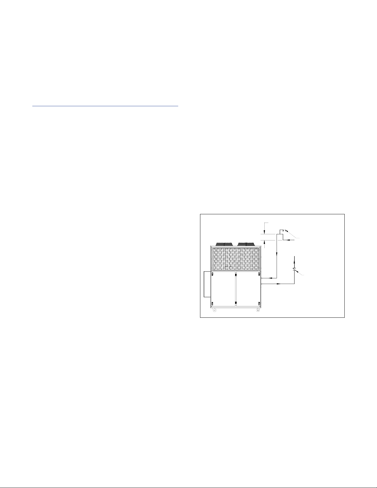
NOTE:
If piping is above chiller and exceeds 90 feet in total
length, install an inverted P-trap and vacuum break
valve in return line and add a check valve to the
supply line.
Check valve
1/2 inch vacum break valve
12 inches above highest
point in piping system
12 inches above highest point
in the piping system
½ inch vacuum
break valve
Check valve
Unit Storage
When storing the unit it is important to protect it
from damage. Blow out any water from the unit;
cover it to keep dirt and debris from accumulating or
getting in, and store in an indoor sheltered area that
does not exceed 145°F.
Installation - Chiller
Foundation
Install the chiller on a rigid, non-warping mounting
pad, concrete foundation, or level floor suitable to
support the full operating weight of the equipment.
When installed the equipment must be level within
¼ inch over its length and width.
Unit Location
The unit is available in many different configurations
for various environments. Refer to the proposal and
order acknowledgement document for the
equipment to verify the specific design conditions in
which it can operate.
To ensure proper airflow and clearance space for
proper operation and maintenance allow a minimum
of 36 inches of clearance between the sides of the
equipment and any walls or obstructions. Avoid
locating piping or conduit over the unit to ensure
easy access with an overhead crane or lift to lift out
heavier components during replacement or service.
In addition, ensure the condenser and evaporator
refrigerant pressure relief valves can vent in
accordance with all local and national codes.
Air-cooled chillers use the surrounding air for
cooling the condenser and require free passage of
air in and out of the chiller and provision for remove
of the warm air from the area.
Rigging
The chiller has a frame to facilitate easy movement
and positioning with a crane or forklift. Follow
proper rigging methods to prevent damage to
components. Avoid impact loading caused by
sudden jerking when lifting or lowering the chiller.
Use pads where abrasive surface contact may occur.
Chilled Process Fluid Piping
Proper insulation of chilled process fluid piping is
crucial to prevent condensation. The formation of
condensation adds a substantial heat load to the
chiller.
The importance of properly sized piping cannot be
overemphasized. See the ASHRAE Handbook or
other suitable design guide for proper pipe sizing. In
general, run full size piping out to the process and
reduce pipe size at connections as needed. One of
the most common causes of unsatisfactory chiller
performance is poor piping system design. Avoid
long lengths of hoses, quick disconnect fittings, and
manifolds wherever possible as they offer high
resistance to water flow. When manifolds are
required, install them as close to the use point as
possible. Provide flow-balancing valves at each
machine to assure adequate water distribution in the
entire system. Typically, when piping is overhead
with a total run length over 90 feet there should be a
valve in the supply line and an inverted P trap with a
vacuum break valve installed as shown in Figure 1.
Figure 1 – Recommended Overhead Piping
All standard portable chillers include an internal
coolant pump and reservoir. Nominal coolant flow
rates assume a 10°F rise across the evaporator at
50°F set point and 85°F entering condenser water for
water-cooled chillers or 95°F entering air for integral
air-cooled or remote air-cooled condenser chillers.
Condenser Water Piping
(Water-Cooled Condenser Chillers Only)
The performance of a water-cooled condenser is
dependent on the flow and temperature of the
cooling water used. Insufficient cooling of the
condenser will result in the reduction of cooling
capacity of the chiller and under extreme conditions
may result in the chiller shutting down due to high
3
Page 10

refrigerant pressure. Allowing the condenser to plug
up from contaminants in the condenser water
stream adversely affects performance. In order to
reduce maintenance costs and chiller downtime, a
water treatment program is highly recommended for
the condenser cooling water. Contact our Customer
Service Department for assistance in the proper
procedure for cleaning out any plugged condenser.
The nominal water-cooled condenser is designed for
85°F condenser cooling water supply. Under normal
operation there will be about a 10°F rise through the
condenser resulting in 95°F exiting water. To ensure
proper water flow through the condenser, ensure the
condenser water pump provides at least 25 psi or
water at a flow rate of 3 gpm per ton of chiller
capacity.
Each condenser has a two-way condenser waterregulating valve. The condenser water-regulating
valve controls the amount of water allowed to pass
through the condenser in order to maintain proper
refrigeration pressures in the circuit.
To prevent damage to the condenser and/or waterregulating valve, the water pressure should not
exceed 150 psig.
Installation – Remote Condenser
Chillers designed for use with a remote air-cooled
condenser include a factory-selected remote
condenser. The remote air-cooled condenser
typically ships separately from a different location
than the chiller.
Location
The remote air-cooled condenser is for outdoor use.
Locate the remote condenser in an accessible area.
The vertical air discharge must be unobstructed. The
vertical air discharge must be unobstructed. Allow a
minimum of 48 inches of clearance between the
sides and ends of the condenser and any walls or
obstructions. For installations with multiple
condensers, allow a minimum of 96 inches between
condensers placed side-by-side or 48 inches for
condensers placed end-to-end.
When locating the condenser it is important to
consider access to the components to allow for
proper maintenance and servicing of the unit. Avoid
locating piping or conduit over the unit to ensure
easy access with an overhead crane or lift to lift out
heavier components during replacement or service.
Proper ventilation is another important
consideration when locating the condenser. In
general, locate the unit in an area that will not rise
above 110°F.
Install the unit on a firm, level base no closer than its
width from walls or other condensers. Avoid
locations near exhaust fans, plumbing vents, flues, or
chimneys. Fasten the mounting legs at their base to
the steel or concrete of the supporting structure. For
units mounted on a roof structure, the steel support
base holding the condenser should be elevated
above the roof and attached to the building.
Avoid areas that can create a “micro-climate” such as
an alcove with east, north, and west walls that can be
significantly warmer than surrounding areas. The
condenser needs to have unrestricted airways so it
can easily move cool air in and heated air away.
Consider locating the condenser where fan noise
and vibration transmission into nearby workspaces is
unlikely.
The unit ships on its side with the legs removed to
reduce shipping dimensions and provide more
protection to the coil from possible damage caused
by impact loading over rough roads and transit
conditions.
Lifting
Use only qualified personnel using the proper
equipment when lifting and positioning the
condenser. Lifting brackets or holes are at the
corners for attaching lifting slings. Use spreader bars
when lifting to apply the lifting force vertically.
Under no circumstances use the coil headers or
return bends in the lifting or moving of the
condenser.
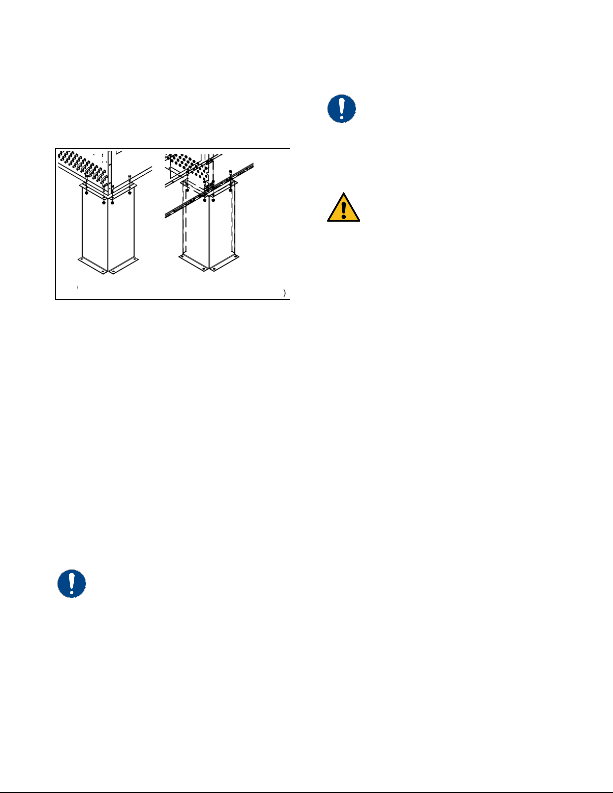
Mounting Legs
Assemble the corner legs to the bottom flanges on
the unit side panels and end panels using the
hardware provided and the matching mounting
hole-patterns. All corner legs are the same. For units
that are longer than three fans, assemble the center
leg. Remove two bolts from the bottom flange of the
unit side panels that match the hole-pattern on the
4
Page 11
CAUTION: Only use refrigerant grade copper tubing
for sizes 5/8” ODS or smaller.
CAUTION: Do not use soft solders. For copper-to-
brazing.
WARNING: The POE oil contained within the
installing the interconnecting refrigerant tubing.
Center Leg
(Right-hand Side Facing Header)
top flanges of both legs. Attached the center legs
using the hardware provide at the center-divider
panel location. Replace the bolts removed from the
side panels to secure the leg assembly to the bottom
flanges of the condenser side panels.
Figure 2 - Mounting Remote Condenser Legs
Interconnecting Refrigerant Piping
The chiller and remote condenser ship with a
nitrogen holding charge. Evacuation of this charge is
required before charging with refrigerant. The chiller
is for use only with the air-cooled condenser
provided with the unit. The following section covers
the required piping between the chiller and the
provided air-cooled condenser.
The discharge and liquid lines leaving the chiller
have caps. These line sizes do not necessarily reflect
the actual line sizes required for the piping between
the chiller and the air-cooled condenser.
Refrigerant piping size and piping design have a
significant impact on system performance and
reliability. All piping should conform to the
applicable local and state codes.
ASTM B280 and isolate the refrigeration lines from
building structures to prevent transfer of vibration. All
copper tubing must have a pressure rating suitable for
R-410A: tubing that is 3/4” OD or larger must be Type
K rigid tubing. ACR annealed tubing coil may be used
Do not use a saw to remove end caps. This might
allow copper chips to contaminate the system. Use a
tube cutter or heat to remove the caps. When
sweating copper joints it is important to evacuate all
refrigerant present and flow dry nitrogen through
the system. This prevents the formation of toxic
gases, corrosive acids, and scale.
copper joints use a copper-phosphorus braze alloy
(BCuP per the American Welding Society) with 5%
(BCuP-3) to 15% (BCuP-5) silver content. Only use a
high silver content brazing alloy (BAg per AWS) for
copper-to-brass or copper-to-steel joints such as a
45% (BAg-5) silver content. Only use oxy-acetylene
compressor is hygroscopic and has the ability to
absorb water vapor from the atmosphere. Take
necessary steps to prevent an open system from
exposure to the atmosphere for extended periods while
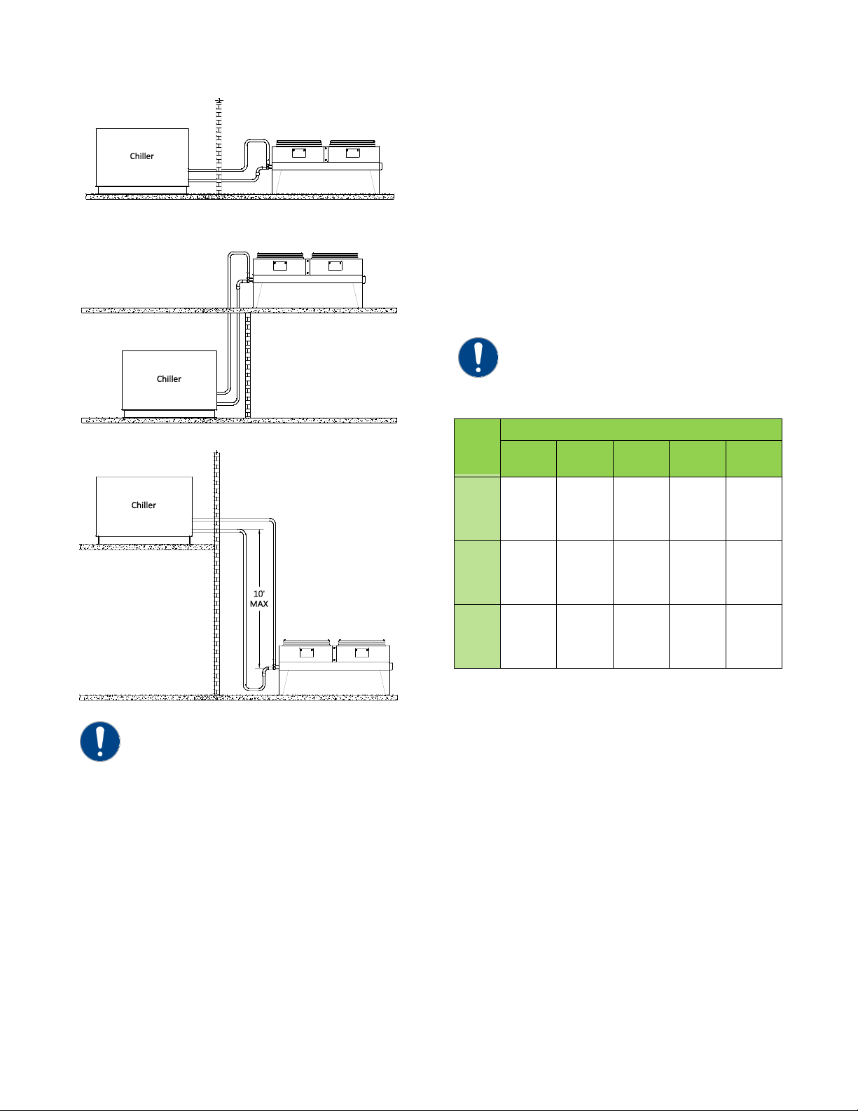
Refrigeration Piping Design
The system is configurable in any of the
arrangements as shown in Figure 3, Figure 4, and
Figure 5. The configuration and its associated
elevation, along with the total distance between the
chiller and the air-cooled condenser are important
factors in determining the liquid line and discharge
line sizes. This will also affect the field refrigerant
charges. Consequently, it is important to adhere to
certain physical limitations to ensure the system
operates as designed.
General design considerations are:
1. The total distance between the chiller and the
air-cooled condenser must not exceed 200
actual feet or 300 equivalent feet. Keep the
distance as short as possible.
2. Liquid line risers must not exceed 15 feet in
height from the condenser liquid line
connection.
3. Discharge line risers cannot exceed an elevation
difference greater than 100 actual feet without a
minimum of 2% efficiency decrease.
4. To form a proper liquid seal at the condenser,
immediately drop at least 15 inches down from
the liquid outlet before routing the piping to the
chiller. Make the drop leg before any bends or
angles connecting to the remainder of the liquid
connection piping.
5
Page 12
Caution: Liquid line sizing for each chiller capacity is
Handbook or other suitable design guide.
CAUTION: When calculating the equivalent length, do
must be considered.
Line
Size OD
Equivalent Lengths of Refrigerant Pipe (feet)
90°
Standard
90°Long
Radius
90°
Street
45°
Standard
45°
Street ⅞ 2.0
1.4
3.2
0.9
1.6
1⅛
2.6
1.7
4.1
1.3
2.1
1⅜
3.3
2.3
5.6
1.7
3.0
1⅝
4.0
2.6
6.3
2.1
3.4
2⅛
5.0
3.3
8.2
2.6
4.5
2⅝
6.0
4.1
10.0
3.2
5.2
3⅛
7.5
5.0
12.0
4.0
6.4
3⅝
9.0
5.9
15.0
4.7
7.3
4⅛
10.0
6.7
17.0
5.2
8.5
Figure 3 – Condenser Located at Chiller Level
Figure 4 – Condenser Located Above Chiller Unit
Figure 5 - Condenser Located Below Chiller Unit
the same pressure loss. See the ASHRAE
Refrigeration Handbook for more information.
Follow these steps when calculating line size:
1. Start with an initial approximation of equivalent
length by assuming that the equivalent length of
pipe is 1.5 times the actual pipe length.
2. Determine approximate line sizes by referring to
Table 2 for liquid lines, Table 3 and Table 4 for
the discharge lines.
3. Check the line size by calculating the actual
equivalent length using the equivalent lengths
as shown in Table 1.
not include piping of the chiller unit. Only field piping
Table 1 – Equivalent Lengths of Elbows
(in)
shown in Table 2. These line sizes are listed per circuit
and apply where leaving water temperature (LWT) is
40°F or higher. For applications where the LWT is
below 40°F, size lines using the ASHRAE Refrigeration
Determining Equivalent Line Length
To determine the appropriate size for field installed
liquid and discharge lines, it is first necessary to
establish the equivalent length of pipe for each line.
The equivalent length is the approximate friction loss
from the combined linear run of pipe and the
equivalent feet of elbows, valves, and other
components in the refrigeration piping. The sum
total is the equivalent length of pipe that would have
Liquid Line Sizing
The liquid line diameter should be as small as
possible while maintaining acceptable pressure drop.
This is necessary to minimize refrigerant charge. The
total length between the chiller unit and the aircooled condenser must not exceed 200 actual feet
or 300 equivalent feet. It is best to pipe the liquid
line so that there is an immediate drop of at least 15
inches at the condenser outlets to make a liquid seal.
Liquid line risers in the system will require an
additional 0.5 psig pressure drop per foot of vertical
rise. When it is necessary to have a liquid line riser,
make the vertical run immediately after the
condenser before any additional restrictions. The
liquid line risers must not exceed 10 feet in height
from the condenser liquid line connection. The liquid
line does not require pitching. Install a pressure tap
6
Page 13

5 Ton Circuit (R410A) Liquid Line Size (Inch OD)
7½ Ton Circuit (R410A) Liquid Line Size (Inch OD)
Up Flow (Feet of Run)
Up Flow (Feet of Run)
0 to 5
6 to 10
11 to 15
0 to 5
6 to 10
11 to 15
25
1/2
1/2
1/2
1/2
25
5/8
5/8
5/8
5/8
50
1/2
1/2
1/2
5/8
50
5/8
5/8
5/8
5/8
75
1/2
1/2
1/2
5/8
75
5/8
5/8
5/8
3/4
100
1/2
1/2
5/8
5/8
100
5/8
5/8
5/8
3/4
125
1/2
1/2
5/8
3/4
125
5/8
5/8
3/4
3/4
150
1/2
5/8
5/8
3/4
150
5/8
5/8
3/4
7/8
175
5/8
5/8
5/8
3/4
175
5/8
5/8
3/4
7/8
200
5/8
5/8
5/8
3/4
200
5/8
3/4
3/4
7/8
225
5/8
5/8
5/8
3/4
225
5/8
3/4
3/4
7/8
250
5/8
5/8
5/8
3/4
250
5/8
3/4
3/4
7/8
275
5/8
5/8
3/4
3/4
275
3/4
3/4
3/4
7/8
300
5/8
5/8
3/4
7/8
300
3/4
3/4
3/4
7/8
10 Ton Circuit (R410A) Liquid Line Size (Inch OD)
15 Ton Circuit (R410A) Liquid Line Size (Inch OD)
Equivalent
Horizontal or
Up Flow (Feet of Run)
Equivalent
Horizontal or
Up Flow (Feet of Run)
0 to 5
6 to 10
11 to 15
0 to 5
6 to 10
11 to 15
25
3/4
3/4
3/4
3/4
25
7/8
7/8
7/8
7/8
50
3/4
3/4
3/4
3/4
50
7/8
7/8
7/8
7/8
75
3/4
3/4
3/4
3/4
75
7/8
7/8
7/8
7/8
100
3/4
3/4
3/4
7/8
100
7/8
7/8
7/8
1 1/8
125
3/4
3/4
3/4
7/8
125
7/8
7/8
7/8
1 1/8
150
3/4
3/4
3/4
7/8
150
7/8
7/8
7/8
1 1/8
175
3/4
3/4
3/4
7/8
175
7/8
7/8
7/8
1 1/8
200
3/4
3/4
7/8
1 1/8
200
7/8
7/8
1 1/8
1 1/8
225
3/4
3/4
7/8
1 1/8
225
7/8
7/8
1 1/8
1 1/8
250
3/4
3/4
7/8
1 1/8
250
7/8
7/8
1 1/8
1 1/8
275
3/4
3/4
7/8
1 1/8
275
7/8
7/8
1 1/8
1 1/8
300
3/4
7/8
7/8
1 1/8
300
7/8
7/8
1 1/8
1 1/8
valve at the condenser to facilitate measuring
pressure for service.
Liquid lines do not typically require insulation.
However, if exposing the lines to solar heat gain or
temperatures exceeding 110 °F, there is a negative
Table 2 – Liquid Line Sizes for R410A
Equivalent
Length (Ft)
Horizontal or
Down Flow
effect on sub-cooling. In these situations, insulate
the liquid lines.
Equivalent
Length (Ft)
Horizontal or
Down Flow
Length (Ft)
Down Flow
Length (Ft)
Down Flow
7
Page 14

20 Ton Circuit (R410A) Liquid Line Size (Inch OD)
25 Ton Circuit (R410A) Liquid Line Size (Inch OD)
Equivalent
Horizontal or
Up Flow (Feet of Run)
Equivalent
Horizontal or
Up Flow (Feet of Run)
0 to 5
6 to 10
11 to 15
0 to 5
6 to 10
11 to 15
25
1 1/8
1 1/8
1 1/8
1 1/8
25
1 1/8
1 1/8
1 1/8
1 1/8
50
1 1/8
1 1/8
1 1/8
1 1/8
50
1 1/8
1 1/8
1 1/8
1 1/8
75
1 1/8
1 1/8
1 1/8
1 1/8
75
1 1/8
1 1/8
1 1/8
1 1/8
100
1 1/8
1 1/8
1 1/8
1 1/8
100
1 1/8
1 1/8
1 1/8
1 1/8
125
1 1/8
1 1/8
1 1/8
1 1/8
125
1 1/8
1 1/8
1 1/8
1 1/8
150
1 1/8
1 1/8
1 1/8
1 1/8
150
1 1/8
1 1/8
1 1/8
1 3/8
175
1 1/8
1 1/8
1 1/8
1 1/8
175
1 1/8
1 1/8
1 1/8
1 3/8
200
1 1/8
1 1/8
1 1/8
1 3/8
200
1 1/8
1 1/8
1 1/8
1 3/8
225
1 1/8
1 1/8
1 1/8
1 3/8
225
1 1/8
1 1/8
1 1/8
1 3/8
250
1 1/8
1 1/8
1 1/8
1 3/8
250
1 1/8
1 1/8
1 1/8
1 3/8
275
1 1/8
1 1/8
1 1/8
1 3/8
275
1 1/8
1 1/8
1 1/8
1 3/8
300
1 1/8
1 1/8
1 1/8
1 3/8
300
1 1/8
1 1/8
1 3/8
1 3/8
30 Ton Circuit (R410A) Liquid Line Size (Inch OD)
35 Ton Circuit (R410A) Liquid Line Size (Inch OD)
Equivalent
Horizontal or
Up Flow (Feet of Run)
Equivalent
Horizontal or
Up Flow (Feet of Run)
0 to 5
6 to 10
11 to 15
0 to 5
6 to 10
11 to 15
25
1 1/8
1 1/8
1 1/8
1 1/8
25
1 3/8
1 3/8
1 3/8
1 3/8
50
1 1/8
1 1/8
1 1/8
1 1/8
50
1 3/8
1 3/8
1 3/8
1 3/8
75
1 1/8
1 1/8
1 1/8
1 1/8
75
1 3/8
1 3/8
1 3/8
1 3/8
100
1 1/8
1 1/8
1 1/8
1 3/8
100
1 3/8
1 3/8
1 3/8
1 3/8
125
1 1/8
1 1/8
1 1/8
1 3/8
125
1 3/8
1 3/8
1 3/8
1 3/8
150
1 1/8
1 1/8
1 1/8
1 3/8
150
1 3/8
1 3/8
1 3/8
1 3/8
175
1 1/8
1 1/8
1 1/8
1 3/8
175
1 3/8
1 3/8
1 3/8
1 3/8
200
1 1/8
1 1/8
1 1/8
1 3/8
200
1 3/8
1 3/8
1 3/8
1 5/8
225
1 1/8
1 1/8
1 3/8
1 3/8
225
1 3/8
1 3/8
1 3/8
1 5/8
250
1 1/8
1 1/8
1 3/8
1 5/8
250
1 3/8
1 3/8
1 3/8
1 5/8
275
1 1/8
1 1/8
1 3/8
1 5/8
275
1 3/8
1 3/8
1 3/8
1 5/8
300
1 1/8
1 1/8
1 3/8
1 5/8
300
1 3/8
1 3/8
1 3/8
1 5/8
Table 2 – Liquid Line Sizes for R410A (continued)
Length (Ft)
Length (Ft)
Down Flow
Down Flow
Length (Ft)
Length (Ft)
Down Flow
Down Flow
8
Page 15

40 Ton Circuit (R410A) Liquid Line Size (Inch OD)
Equivalent
Horizontal or
Up Flow (Feet of Run)
0 to 5
6 to 10
11 to 15
25
1 3/8
1 3/8
1 3/8
1 3/8
50
1 3/8
1 3/8
1 3/8
1 3/8
75
1 3/8
1 3/8
1 3/8
1 3/8
100
1 3/8
1 3/8
1 3/8
1 3/8
125
1 3/8
1 3/8
1 3/8
1 3/8
150
1 3/8
1 3/8
1 3/8
1 5/8
175
1 3/8
1 3/8
1 3/8
1 5/8
200
1 3/8
1 3/8
1 3/8
1 5/8
225
1 3/8
1 3/8
1 3/8
1 5/8
250
1 3/8
1 3/8
1 3/8
1 5/8
275
1 3/8
1 3/8
1 3/8
1 5/8
300
1 3/8
1 3/8
1 3/8
1 5/8
Note: Discharge line sizing shown in Table 3and Table
guide.
Table 2 – Liquid Line Sizes for R410A (continued)
Length (Ft)
Down Flow
Discharge (Hot Gas) Line Sizing
The discharge line sizes depend on the velocity
needed to obtain sufficient oil return. It is very
important to minimize line length and restrictions to
reduce pressure drop and maximize capacity.
Upflow hot gas risers need to have a trap at the
bottom and reverse trap at the top. In addition, a
trap and reverse trap arrangement needs to be
spaced every 15 feet in the rise for oil management
(see Figure 6).
The discharge lines should pitch downward, in the
direction of the hot gas flow, at the rate of ½ inch
per each 10 foot of horizontal run. If the chiller unit
is below the condenser, loop the discharge line to at
least 1 inch above the top of the condenser. Install a
pressure tap valve at the condenser to facilitate
measuring pressure for service. Take careful
consideration in the design of the discharge gas
riser.
Check the oil-level sight glass in the compressor to
ensure it is at the appropriate level to verify there is
no trapping of oil in the piping. The chiller is
equipped with hot-gas bypass capacity control and
the gas in the upflow discharge lines may have
problems moving the oil against gravity when
completely unloaded if a single rise system is used.
We recommend a double riser system to ensure
proper oil return under low load operation. See
Figure 7 and Table 4 for double riser constructions.
Figure 6 – Vertical Riser Traps
Figure 7 - Double Discharge Riser
4 are listed per circuit and apply where leaving water
temperature (LWT) is 40°F or higher. For applications
where LWT is below 40°F, size lines using the ASHRAE
Refrigeration Handbook or other suitable design
9
Page 16

Total Equivalent Length (Ft)
25
50
75
100
125
150
175
200
225
250
275
300 5 5/8
5/8
5/8
5/8
3/4
3/4
3/4
3/4
3/4
3/4
3/4
7/8
7.5
7/8
7/8
7/8
7/8
7/8
7/8
7/8
7/8
7/8
7/8
7/8
7/8
10
7/8
7/8
7/8
7/8
7/8
7/8
7/8
1 1/8
1 1/8
1 1/8
1 1/8
1 1/8
15
7/8
7/8
1 1/8
1 1/8
1 1/8
1 1/8
1 1/8
1 1/8
1 1/8
1 1/8
1 3/8
1 3/8
20
7/8
1 1/8
1 1/8
1 3/8
1 3/8
1 3/8
1 3/8
1 3/8
1 3/8
1 3/8
1 5/8
1 5/8
25
1 1/8
1 1/8
1 1/8
1 3/8
1 3/8
1 3/8
1 3/8
1 3/8
1 3/8
1 3/8
1 5/8
1 5/8
30
1 1/8
1 1/8
1 1/8
1 3/8
1 3/8
1 3/8
1 3/8
1 3/8
1 3/8
1 5/8
1 5/8
1 5/8
35
1 3/8
1 3/8
1 3/8
1 5/8
1 5/8
1 5/8
1 5/8
2 1/8
2 1/8
2 1/8
2 1/8
2 1/8
40
1 5/8
1 5/8
1 5/8
1 5/8
1 5/8
1 5/8
2 1/8
2 1/8
2 1/8
2 1/8
2 1/8
2 1/8
Total Equivalent Length (Ft)
25
50
75
100
125
150
175
200
225
250
275
300
A – 3/8
A – 3/8
A – 3/8
A – 3/8
A – 3/8
A – 3/8
A – 3/8
A – 3/8
A – 3/8
A – 3/8
A – 3/8
A – 3/8
B – 1/2
B – 1/2
B – 1/2
B – 1/2
B – 5/8
B – 5/8
B – 5/8
B – 5/8
B – 5/8
B – 5/8
B – 5/8
B – 3/4
A – 3/8
A – 3/8
A – 3/8
A – 3/8
A – 3/8
A – 3/8
A – 3/8
A – 3/8
A – 3/8
A – 3/8
A – 3/8
A – 3/8
B – 3/4
B – 3/4
B – 3/4
B – 3/4
B – 3/4
B – 3/4
B – 3/4
B – 3/4
B – 3/4
B – 3/4
B – 3/4
B – 3/4
A – 3/8
A – 3/8
A – 3/8
A – 3/8
A – 3/8
A – 3/8
A – 3/8
A – 3/8
A – 3/8
A – 3/8
A – 3/8
A – 3/8
B – 3/4
B – 3/4
B – 3/4
B – 3/4
B – 3/4
B – 3/4
B – 3/4
B – 7/8
B – 7/8
B – 7/8
B – 7/8
B – 7/8
A – 3/8
A – 3/8
A – 3/8
A – 3/8
A – 3/8
A – 3/8
A – 3/8
A – 3/8
A – 3/8
A – 3/8
A – 1/2
A – 1/2
B – 3/4
B – 3/4
B – 7/8
B – 7/8
B – 7/8
B – 7/8
B – 7/8
B – 7/8
B – 7/8
B – 7/8
B – 1 1/8
B – 1 1/8
A – 3/8
A – 3/8
A – 3/8
A – 1/2
A – 1/2
A – 1/2
A – 1/2
A – 1/2
A – 1/2
A – 1/2
A – 5/8
A – 5/8
B – 3/4
B – 7/8
B – 7/8
B – 1 1/8
B – 1 1/8
B – 1 1/8
B – 1 1/8
B – 1 1/8
B – 1 1/8
B – 1 1/8
B – 1 3/8
B – 1 3/8
A – 3/8
A – 3/8
A – 3/8
A – 1/2
A – 1/2
A – 1/2
A – 1/2
A – 1/2
A – 1/2
A – 1/2
A – 5/8
A – 5/8
B – 7/8
B – 7/8
B – 7/8
B – 1 1/8
B – 1 1/8
B – 1 1/8
B – 1 1/8
B – 1 1/8
B – 1 1/8
B – 1 1/8
B – 1 3/8
B – 1 3/8
A – 1/2
A – 1/2
A – 1/2
A – 3/4
A – 3/4
A – 3/4
A – 3/4
A – 3/4
A – 3/4
A – 3/4
A – 3/4
A – 3/4
B – 7/8
B – 7/8
B – 7/8
B – 1 1/8
B – 1 1/8
B – 1 1/8
B – 1 1/8
B – 1 1/8
B – 1 1/8
B – 1 3/8
B – 1 3/8
B – 1 3/8
A – 3/4
A – 3/4
A – 3/4
A – 3/4
A – 3/4
A – 3/4
A – 3/4
A – 3/4
A – 3/4
A – 3/4
A – 3/4
A – 3/4
B – 1 1/8
B – 1 1/8
B – 1 1/8
B – 1 3/8
B – 1 3/8
B – 1 3/8
B – 1 3/8
B – 1 5/8
B – 1 5/8
B – 1 5/8
B – 1 5/8
B – 1 5/8
A – 3/4
A – 3/4
A – 3/4
A – 3/4
A – 3/4
A – 3/4
A – 3/4
A – 3/4
A – 3/4
A – 3/4
A – 3/4
A – 3/4
B – 1 3/8
B – 1 3/8
B – 1 3/8
B – 1 3/8
B – 1 3/8
B – 1 3/8
B – 1 5/8
B – 1 5/8
B – 1 5/8
B – 1 5/8
B – 1 5/8
B – 1 5/8
Table 3 - Horizontal or Downflow Discharge Line Sizes for R410A (inches OD)
Circuit
Tons
Table 4 - Upflow Discharge Line Sizes for R410A (inches OD)
Circuit
Tons
5
7.5
10
15
20
25
30
35
40
10
Page 17

Total Combined Chiller and Condenser
R410A) 5 7.6
7.5
11.1
10
15.3
15
22.2
20
30.2
25
37.2
30
44.3
35
51.9
40
59.4
Line Size OD
Lbs of R410A per 100 Foot of Line Length
Discharge Line
Liquid Line
3/8
0.4
3.7
1/2
0.7
6.8
5/8
1.1
11
3/4
1.6
16.4
7/8
2.2
22.8
1 1/8
3.6
36.7
1 3/8
5.6
57.4
1 5/8
7.9
81.2
2 1/8
13.9
142.1
2 5/8
21.4
219.5
Number of Fan Stages
1 2 3
4
Max Speed
410
410
410
410
Min Speed
320
320
320
320
Fan On
400
400
370
Fan Off
340
340
305
Fan On
435
385
Fan Off
375
325
Fan On
400
Fan Off
340
Calculating Refrigerant and Oil Charge
To determine the approximate charge, first refer to
Table 12 and establish the required charge for the
condenser and chiller. Then refer to Table 13 to
determine the charge required for the field-installed
piping per circuit. The approximate charge per circuit
is therefore the sum of the values from Table 12 and
Table 13.
Table 5 – Chiller & Condenser Refrigerant Charge
Circuit Capacity
(tons)
Summertime Refrigerant Charge (lbs of
Oil level should be checked after the chiller has run
for 15 minutes.
Setting Condenser Fan Controls
Depending on the number of condenser fans
present there will be different fan cycling pressure
control setting requirements. It is important that
these settings be correct in order to maintain proper
capacity control and operation of the system. Each
refrigerant circuit has a separate head-pressure
control circuit. Refer to Table 7 for the proper
pressure settings.
Table 7 - Condenser Fan Pressure Settings (psig)
Stage
Number
Stage 1
Stage 2
Stage 3
Setting
Table 6 - Field Piping R-410A Refrigerant Charges
(inches)
Oil Charge Determination
The chiller is factory charged with the amount of oil
required by the chiller only and not the total system.
The amount of oil required is dependent upon the
amount of refrigerant added to the system for the
field-installed piping. Use the following to determine
the amount of oil needed for the system.
Pints of Oil = Pounds of refrigerant in system / 100
Stage 4
To do this, open the remote condenser control
panel, remove the cover from the pressure control
module, and make sure everything is set as shown
below.
11
Page 18

WARNING: This equipment contains hazardous
WARNING: This equipment contains refrigerant under
damage.
WARNING: This equipment may contain fan blades or
protective shields are securely in place.
WARNING: The exposed surfaces of motors, refrigerant
hands.
CAUTION: Disconnect and lock out incoming power
maintenance.
CAUTION: Wear eye protection when installing,
against any sparks, debris, or fluid leaks.
CAUTION: Wear protective gloves when installing,
against any sparks, debris, or fluid leaks.
CAUTION: Wire the unit ground in compliance with
CAUTION: The unit requires the main power to remain
24 hours prior to initial startup.
Installation - Electrical
All wiring must comply with local codes and the
National Electric Code. Minimum circuit amps (MCA)
and other unit electrical data are on the unit
nameplate. A unit specific electrical schematic ships
with the unit. Measure each leg of the main power
supply voltage at the main power source. Voltage
must be within the voltage utilization range given on
the drawings included with the unit. If the measured
voltage on any leg is not within the specified range,
notify the supplier and correct before operating the
unit. Voltage imbalance must not exceed two
percent. Excessive voltage imbalance between the
phases of a three-phase system can cause motors to
overheat and eventually fail. Voltage imbalance is
determined using the following calculations:
%Imbalance = (Vavg – Vx) x 100 / Vavg
Vavg = (V1 + V2 + V3) / 3
Vx = phase with greatest difference from Vavg
For example, if the three measured voltages were
442, 460, and 454 volts, the average would be:
(442 + 460 + 454) / 3 = 452
The percentage of imbalance is then:
(452 – 442) x 100 / 452 = 2.2 %
This exceeds the maximum allowable of 2%.
There is a terminal block for main power connection
to the main power source. The main power source
should be connected to the terminal block through
an appropriate disconnect switch. There is a separate
lug in the main control panel for grounding the unit.
Check the electrical phase sequence at installation
and prior to start-up. Operation of the compressor
with incorrect electrical phase sequencing will result
in mechanical damage to the compressors. Check
the phasing with a phase sequence meter prior to
applying power. The proper sequence should read
“ABC” on the meter. If the meter reads “CBA”, open
the main power disconnect and switch two line leads
on the line power terminal blocks (or the unit
mounted disconnect). Do not interchange any load
leads that are from the unit contactors or the motor
terminals.
voltages that can cause severe injury or death.
pressure. Accidental release of refrigerant under
pressure can cause personal injury and or property
other sharp edges. Make sure all fan guards and other
piping, and other fluid circuit components can be very
hot and can cause burns if touched with unprotected
before installing, servicing, or maintaining the
equipment. Connecting power to the main terminal
block energizes the entire electric circuitry of the unit.
Electric power at the main disconnect should be shut
off before opening access panels for repair or
maintaining, or repairing the equipment to protect
maintaining, or repairing the equipment to protect
local and national codes.
connected during off-hours to energize the
compressor’s crankcase heater. Disconnect main
power only when servicing the chiller. The crankcase
heater should remain on when the compressor is off to
ensure liquid refrigerant does not accumulate in the
compressor crankcase. Connect main power at least
12
Page 19

Button
Description of Operation
Start
Depressing the Start button will start the pump and enable the compressor. The compressor (and condenser fans if the
The Start button also performs an “Enter” function while in the programming menu.
Stop
Depressing the Stop button will shut off the compressor, pump, condenser fans (if the chiller is air-cooled), and clear all
also performs a “Cancel” function while in the programming menu.
Alarm Silence /
When an alarm condition is present, the alarm light is on and red. The first Alarm Silence/Reset button press will silence
immediately go into a new alarm state.
Compressor
Press and hold the Compressor Running Hours Button to display the amount of time that each compressor in the system
hours is in units of hundreds so a display value
is not disturbed while displaying the running hours.
Pump Running
Press and hold the Pump Running Hours Button to display the amount of time the pump has run. The running hours
running hours is in units of hundreds so a display value of 10 would mean
running hours.
Standard Controller Operation
The chiller includes a controller to perform all
control functions directly from the front panel. When
Control Power is applied, the controller initiates a
diagnostic test of each indicating light and display
segments by briefly lighting each sequentially. As
part of this initial diagnostic test, the program
revision level displays for a moment. After the initial
diagnostic sequence is completed, the controller is
ready for operation.
Table 8 - Operating Buttons
chiller is air-cooled) will start only if the microprocessor is calling for cooling because the actual To Process temperature
is higher than the Set Point temperature. If the Autostart feature is enabled the Autostart signal will have precedence
over the Start Button. See the
fault signals. If the Autostart feature is enabled and an Autostart signal is present, the Stop button will not stop the
chiller. See the
Alarm Reset
Running Hours
Hours
the alarm horn (optional), open the remote alarm contact (optional), and the alarm light changes from red to yellow. The
alarm horn and/or remote alarm contact remain disabled until a subsequent alarm occurs. A second press of the Alarm
Silence/Reset button resets the state from Alarm to Normal Operation. The High Refrigerant Pressure and Pump
Overload require a mechanical safety manual reset before the control board reset. If the fault is still present, the unit will
has run. The Set Point window will show which compressor’s usage is being displayed (for units with two compressors).
The running hours show in the process display window. Display of running
of 10 would mean 1,000 hours. The running hours show while holding the button. For units with two compressors, the
display will toggle between the two compressors every three seconds. The hours show while holding the button. Control
show in the process display window. Display of
1,000 hours. The running hours will show while holding the button. Control is not disturbed while displaying the pump
Program Menu section for instructions on how to enable or disable the Autostart feature.
Program Menu section for instructions on how to enable or disable the Autostart feature. The Start button
13
Page 20

Button
Description of Operation
Pump Test
With the chiller stopped, pressing this button briefly engages the pump to test its operation. The pump will not run if
second time. The pump will shut down after one minute of operation.
Display/Program
The Display/Program button will change the temperature displayed in the Process screen from Supply to Return. When
Menu section for more detail.
Up
The Up button raises the set point temperature. Pressing the Up button and releasing it increases the set point
various alarms and set point values when the unit in the programming mode.
Down
The Down button decreases the set point temperature. Pressing the Down button and releasing it decreases the set point
adjusts various alarms and set point values when the unit is in the programming mode.
Display
Description of Operation
Set Point
The Set Point display normally shows the set point temperature. A decimal point in the lower right corner of this display
indicates the temperature unit of measure is set to °F, no decimal point indicates the temperature unit of measure is set to
and programming information.
Process
The Process Temperature display normally shows supply temperature. A decimal point in the lower right corner of the
button press. This display also shows alarm codes and programming information.
Light
Description of Operation
Control Power
The Control Power light is green when 24VDC control voltage is present.
Autostart Signal
The Autostart Signal light is green when closed (run), yellow when open (stop), and unlit if this feature is disabled. This
introduce any external voltage to the Autostart contacts, as this will result in damage to the controller.
Pump
The Pump light is solid green when the pump is running and flashes red if the pump motor overload trips.
Hot Gas Bypass
The Hot Gas Bypass light will pulse or light solidly when the chiller is operating at partial load and the hot gas bypass
temperature may begin to drop below the Set Point temperature, eventually cycling off compressor(s).
Compressor #1
The Compressor #1 light is solid green when Compressor #1 is running, flashes red if a compressor overload or fault
chiller rises above the Set Point by an amount
section for instructions on how to adjust PS1 and nS1.
Table 8 – Operating Buttons (continued)
there are any active alarms. The pump shuts down by either pressing the Stop button or pressing the Pump Test button a
the display is set to supply temperature, there will be an orange indicating light in the lower right corner of the Process
temperature display. When the display is set to return temperature, there will be no orange indicating light in the lower
right corner of the Process temperature display. To toggle the process temperature display from supply to return
temperature, press and release the Display/Program button. The display will return to the default Supply temperature
automatically after 5 seconds without a button press. In addition to switching between the supply and return process
temperature displays, the Display/Program button will initiate and navigate through the program menu. See the
temperature by one degree. Pressing the Up button and holding it increases the set point temperature until reaching the
maximum allowable set point temperature. In addition to adjusting the set point temperature, the Up button adjusts
temperature by one degree. Pressing the Down button and holding it decreases the set point temperature until reaching
the minimum allowable set point temperature. In addition to adjusting the set point temperature, the Down button
Table 9 - Temperature Displays
Program
°C. See the Program Menu section to change the temperature scale units of measure. This display also shows alarm codes
display indicates the temperature displayed is the supply temperature, no decimal point indicates the temperature
displayed is the return temperature. To change the display from supply to return temperature, press and release the
Display/Program button. The display will return to the default Supply temperature automatically after 5 seconds without a
Table 10 - Operating Lights
feature allows starting and stopping of the unit by a remote contact closure. From the factory, the Autostart feature is
disabled. See the
valve opens. The light stays on for longer periods of time when the chiller is under smaller loads. If the light stays off the
chiller is under full load. If the light stays on the chiller is fully unloaded. If this condition persists, the To Process
occurs, and is solid red if the controller is attempting to start the compressor before the anti-recycle timer has timed out.
Compressor #1 is enabled when the temperature of the coolant leaving the
equal to the control parameter PS1 (Compressor #1 Positive Spread). PS1 is equal to 2 °F by default. The compressor is
disabled if the temperature of the coolant leaving the chiller drops below the Set Point by an amount equal to the control
parameter nS1 (Compressor #1 Negative Spread). The parameter nS1 is set to 4 °F by default. See the
Program Menu section for instructions on how to enable or disable the Autostart feature. Do not
Program Menu
14
Page 21

Light
Description of Operation
Compressor #2
The Compressor #2 light is solid green when Compressor #2 is running, flashes red if a compressor overload or fault
chiller rises above the Set Point by an amount
section for instructions on how to adjust PS2 and nS2.
Temperature Limit
The Temperature Limit light flashes yellow if a high or low temperature limit warning occurs and flashes red if a high or
Pushing the Alarm Reset
button will reset this alarm.
Electrical Phase
Error
The Electrical Phase Error light flashes red when a line voltage problem exists (loss of phase, phase reversal, or phase
imbalance). This safety stops all compressors and pumps. Pushing the Alarm Reset button will reset this alarm.
Low Flow
The Low Flow light is red if the flow through the chiller is too low. This safety is defeated for 5 seconds after starting the
the safety and restarts the chiller.
Freezestat
The Freezstat light is red if the coolant leaving the chiller drops below the Freezestat Limit (FLS) setting. This safety stops
to adjust FLS.
Reservoir Level
The Low Reservoir Level light is red when the water level in the reservoir drops below the lower limit of the float switch.
coolant level in the reservoir has risen about the lower limit of the float switch.
Compressor
The Compressor Recycle light is yellow when the number of compressor starts per hour exceeds the number allowed. This
yellow whenever there is a wait period before a compressor can start.
High Refrig
The High Refrigerant Pressure light is red when the compressor discharge refrigerant pressure exceeds the setting of the
refrigerant pressure safety.
Low Refrig
The Low Refrigerant Pressure light is red when the compressor suction pressure drops below the setting on the low
Reset button resets the fault if the compressor suction pressure is above the setting of the low refrigerant pressure safety.
Program Mode
The Program Mode LED flashes yellow when the control system is in the programming menu.
Table 10 – Operating Lights (continued)
occurs, and is solid red if the controller is attempting to start the compressor before the anti-recycle timer has timed out.
Compressor #2 is enabled when the temperature of the coolant leaving the
equal to the control parameter PS2 (Compressor #2 Positive Spread). PS2 is equal to 3 °F by default. The compressor is
disabled if the temperature of the coolant leaving the chiller drops below the Set Point by an amount equal to the control
parameter nS2 (Compressor #2 Negative Spread). The parameter nS2 is set to 5 °F by default. See the
low temperature limit safety occurs. A temperature limit safety stops all compressors and pumps.
chiller to allow the pump to establish flow. This safety stops all compressors and pumps. Pressing the Start button resets
all compressors but allows pumps to continue running. Set the Freezestat Limit 10°F above the freezing point of the
coolant in the chiller. The Freezestat is factory set at 38°F. Pressing the Alarm Reset button resets the Freezestat fault if
the coolant temperature has risen 5°F above the Freezestat Limit. See the
Program Menu
Program Menu section for instructions on how
This safety stops all compressors and pumps. Pressing the Alarm Reset button resets the Low Reservoir Level fault if the
Recycle
Pressure
Pressure
limit maximizes compressor life and ensures proper return of oil to the compressor crankcase. This light is illuminated
high refrigerant pressure safety. This safety stops all compressors but allows pumps to continue running. Pressing the
Alarm Reset button resets the fault if the compressor discharge refrigerant pressure is less than the setting of the high
refrigerant pressure safety. This safety stops all compressors but allows pumps to continue running. Pressing the Alarm
Program Menu
The program menu is password protected to prevent
unintended alteration to the program settings and
parameters. The unit must be in a stopped state for
menu access.
To enter the password press and hold the
Display/Program button for 5 seconds. The Program
Mode light flashes yellow, the Set Point display
shows “000”, and the Process display shows “PAS.”
The unit is now ready to have the password entered.
Use the up and down arrows to change the number
to the correct password and press the Start button
to enter. The default password is “000.”
If the password entered is incorrect, the Set Point
displays “no” and the Process display shows "PAS"
for 5 seconds and then waits for another attempt to
enter the correct password. If no activity occurs for 5
seconds, the controller exits the programming mode
and returns to the Stopped state.
Once in the program menu, use the Display/Program
button to scroll through the different adjustable
parameter as shown in Table 11.
To change an item, press the Display/Program
button until the item code displays in the Process
display. Pressing the Alarm Reset button and
Display/Program button at the same time reverses
the direction the Display/Program button indexes
through the menu items. Once the desired menu
item code shows in the Process display, use the Up
and Down arrow buttons to adjust the value shown
15
Page 22

Default
Value
Alarm delay for high deviation alarm
AdH
30
0 to 60 minutes (10 to 60 minutes on program versions prior to version 1.33)
Alarm delay for low deviation
AdL
30
0 to 60 minutes (10 to 60 minutes on program versions prior to version 1.33)
Alarm deviation alarm delay after
start
Alarm output
AdO
DI S
Disabled (DI S ) or Enabled (EnA) on program versions 1.33 and later only
Autostart enable
AS E
EnA
Disabled (DI S ) or Enabled (EnA)
Brownout monitor
br n
EnA
Disabled (DI S ) or Enabled (EnA)
Communications Baud Rate
1
bAU
96
12 to 96
Communications Modbus ID
1
id
1
1 to 247
Communications SPI Address
1
SPA
32
32 to 63
Communications type
1
C Ot
OF F
OFF, Retransmit (r Et ), SPI (SPI ), ModBus (bUS ), Handheld Remote (Ha n )
Compressor 1 negative spread
nS1
4
1 to 10
Compressor 1 positive spread
PS1
2
1 to 10
Compressor 2 enabled
C O2
DI S
Disabled (DI S ) or Enabled (EnA)
Compressor 2 negative spread
nS2
5
1 to 10
Compressor 2 positive spread
PS2
3
1 to 10
Derivative
dEr
3
0 to 200
Display units
Un t
F
F to C
Freezestat limit
FSL
40
-50 to 40
High deviation alarm limit
HI d
10
5 to 100 degrees about set point
Integral
I nt
25
1 to 800
Low deviation alarm limit
Lod
10
5 to 100 degrees below set point
Panel temperature alarm
PAe
EnA
Disabled (DI S ) or Enabled (EnA)
Panel temperature readout
Pt e
-
Display only
Proportional band
bnd
8
1 to 300
Remote Setpoint High limit
1
r SH
65
Between r SL and 999
Remote Setpoint Low limit
1
r SL
20
Between -99 and r SH
Remote Setpoint Enable
1
r SE
DI S
Disabled (DI S ) or Enabled (EnA)
Retransmit Range High
1
r EH
150
Between 999 and r EL
Retransmit Range Low
1
r EL
0
Between -99 and r EH
User High Safety limit
HS U
140
Between factory low and high limits
User Low Safety limit
LSU
10
Between factory low and high limits
User password
UP A
000
0 to 999
in the Set Point display until the desired value shows.
Press the Start button to enter the new value. Press
the Stop button to cancel and revert to the previous
value.
There is a Master Reset function to restore all User
menu parameters to their factory default values. The
unit must be in a stopped state for this function to
work. To initiate a Master Reset press and hold the
Table 11 - Controller Program Menu
Item Name Item Code
ADS 30
0 to 30 minutes on program version 1.33 and later only
Alarm Silence/Reset button and Stop button
simultaneously for 10 consecutive seconds until
“PRG” shows on the Set Point display and "RSt"
shows on the Process display. Release all buttons
and press the Start button within 10 seconds. Failure
to push the Start button within 10 seconds aborts
the Master Reset.
Range
1
Optional, requires additional hardware to be functional.
16
Page 23

Component Shut-Off
Required Resets
Pump
Compressor
Panel
2
Sensor
3
Low Reservoir Level
Reservoir Level Light flashes red
Yes
Yes
Yes
Yes
Temperature Limit Safety
Set Point and Process Displays Flash, Temperature
Limit Light flashes red
Temperature Limit Warning
Temperature Limit Light flashes yellow
No
No
Yes
No
Pump Motor Overload
Pump Light flashes red
Yes
Yes
Yes
Yes
Compressor Motor Overload
Compressor Light flashes red
No
Yes
Yes
No
High Refrigerant Pressure
High Refrig Pressure Light flashes red
No
Yes
Yes
Yes
Low Refrigerant Pressure
Low Refrig Pressure Light flashes red
No
Yes
Yes
No
Low Evaporator Temperature
Freezestat Light flashes red
No
Yes
Yes
No
Supply Probe Fault Hi
Set Point Display shows
, Process Display shows
E Hi
Supply Probe Fault Lo
Set Point Display shows
, Process Display shows
ELo
Return Probe Fault Hi
Set Point Display shows
, Process Display shows
E Hi
Return Probe Fault Lo
Set Point Display shows
, Process Display shows
ELo
Freezestat Probe Fault Hi
Set Point Display shows
, Process Display shows
E Hi
Freezestat Probe Fault Lo
Set Point Display shows
, Process Display shows
ELo
Brownout
Set Point Display shows
, Process Display shows
Out
3-Phase Power Error
Electrical Phase Error list flashes red
Yes
Yes
Yes
No
Low Flow
Low Flow Light flashes red
Yes
Yes
No
No
Table 12 – Controller Control Fault Logic
1
Fault
Alarm Indication
Yes Yes Yes No
PRS
PRS
PRR
PRR
PRF
PRF
Br n
1
Activates the alarm horn (optional) and closes the alarm contact (optional) if these options have been purchased.
2
Alarm Silence/Reset button on control panel must be pressed.
3
Safety control device must be manually reset before the controller can be reset.
Yes Yes Yes No
Yes Yes Yes No
Yes Yes Yes No
Yes Yes Yes No
Yes Yes Yes No
Yes Yes Yes No
Yes Yes Yes No
SPI Communications (Optional)
Several years ago, a number of members of The
Plastics Industry Association developed a standard
for various pieces of plastic processing equipment to
communicate. They chose to adopt the Serial
Peripheral Interface bus (SPI bus). To allow our unit
to operate as a slave unit in a plastic processing
system using this protocol, we offer an option that
includes an expansion module for the control board
and a RS-485 communication port on the unit. The
communication hardware firmware is SPI 3.01
standard compliant.
Units ordered with this option will have this feature
activated at the factory. Use the program menu
Communication Type function as shown in Table 11
to activate or deactivate this feature. In addition to
activating the communication type a baud rate and
SPI address must be set. These are set using the
Communication Baud Rate and SPI Address
functions as shown in Table 13.
If multiple pieces of equipment are going to be on
the same SPI communications network, the base
addresses of each machine has to be unique. The
communication baud rate may also need
adjustment.
17
Page 24

Command
Poll
Select
Description
Echo
20 20
20 21
This is the controller integrity command used to accept and retain data and provide it
in response to a poll inquiry. This is an open 4-byte ASCII format with ASCII units.
Version
20 22
This is the controller version command used to provide a version number following
level. This is in an open 4-byte ASCII format with ASCII units.
Setpoint Process
Temperature
20 30
20 31
This is the temperature target for the supply coolant leaving the chiller. This is a
numeric format in °F.
Alarm, High Temperature
Deviation
20 32
20 33
This is the value in conjunction with the process setpoint that determines the high
alarm temperature. This value must always be positive. This is a numeric format in °F.
Alarm, Low Temperature
Deviation
20 34
20 35
This is the value in conjunction with the process setpoint that determines the low alarm
temperature. This value must always be positive. This is a numeric format in °F.
Status, Process
20 40
This is the process status in a 16 bit format as follows:
5 = The controller has exceeded its below setpoint deviation
Status, Machine 1
This is the machine status in a 16 bit format as follows:
5 = The controller has exceeded its below setpoint deviation
Status, Machine 2
This is the machine status in a 16 bit format as follows:
4 = An alarm affecting the machine operation has occurred
Mode, Machine
20 48
20 40
This is the machine mode in two 8-bit bytes. When polling 20 48 bit 0 indicates the
off when low), 20 40 bit 1 is used to recognized the alarm condition
Temperature, To Process
(Supply)
20 70
Returns the process supply temperature.
This is a numeric format in °F.
Temperature, To Process
(Return)
20 72
Returns the process return temperature.
This is a numeric format in °F.
Register
Description
Read/Write
Format
Notes
Integer
0 = Off, 1 = Stop, 2 = Run, 3 = Run Fault 2,
9 = Master Reset
4007
Derivative
R/W
Integer
4008
Integral
R/W
Integer
Table 13 - SPI Parameters
format: AABB, where AA = SPI assigned version level, BB = vendor assigned version
0 = Controlling
1 = An alarm is present
2 = An alarm affecting the process has occurred (high or low temperature deviation)
3 = An alarm affecting the machine has occurred (probe fault or pump fault)
4 = The controller has exceeded its over setpoint deviation
20 42
0 = Controlling
1 = An alarm is present
2 = An alarm affecting the process has occurred (high or low temperature deviation)
3 = An alarm affecting the machine operation has occurred (probe fault or pump fault)
4 = The controller has exceeded its over setpoint deviation
20 44
0 = Controlling
1 = An alarm is present
2 = An alarm affecting the process has occurred (high or low temperature deviation)
3 = A sensor error has been detected
machine is off. 20 40 bit 0 commands the unit to be turned on or off (on when high or
Modbus RTU (Optional)
This option provides a RS-485 communications port for Modbus RTU communications. See Table 11 for details on
how to enable this feature. Note the ModBus Parity = None, Stop Bits = 1, and default Baud Rate = 9,600.
Table 14 – Standard Controller Modbus RTU Option Parameters
4002 Machine State R
4 = Run Fault 3, 5 = Fault 1, 6 = Factory Menu,
7 = User Menu, 8 = Get User Password,
18
Page 25

Register
Description
Read/Write
Format
Notes
4011
Low Alarm Delay
R
Integer
4012
High Alarm Delay
R
Integer
4013
Temperature Display Units
R
Integer
0 = °F, 1 = °C
4015
Brownout Enabled
R
Integer
0 = Disabled, 1 = Enabled
4024
Remote Setpoint Enabled
R
Integer
0 = Disabled, 1 = Enabled
4025
Autostart Enabled
R
Integer
0 = Disabled, 1 = Enabled
4027
Communication BAUD Rate
R/W
Integer
0 = 1200, 1 = 2400, 2 = 4800, 3 = 9600
4028
MODBUS Identification
R/W
Integer
4030
SPI Communications Address
R/W
Integer
4033
Compressor 2 Enabled
R
Integer
0 = Disabled, 1 = Enabled
4038
Hot Gas Bypass PID Output
R
Integer
-100 to 100 PID algorithm output
4039
MODBUS Command
R/W
Integer
0 = Do Nothing, 1 = Start, 2 = Stop
8000
Freezestat Temperature (°C)
R
Floating Point
Error Hi = 9.9E05, Error Low = -9.9E05
8002
Supply Fluid Temperature (°C)
R
Floating Point
Error Hi = 9.9E05, Error Low = -9.9E05
8004
Return Fluid Temperature (°C)
R
Floating Point
Error Hi = 9.9E05, Error Low = -9.9E05
8010
Low Temperature Deviation (°C)
R/W
Floating Point
8012
High Temperature Deviation (°C)
R/W
Floating Point
8014
Low Setpoint Limit Temperature (°C)
R
Floating Point
8016
High Setpoint Limit Temperature (°C)
R
Floating Point
8018
Supply Temperature Retransmit Range Low (°C)
R
Floating Point
8020
Supply Temperature Retransmit Range High (°C)
R
Floating Point
8022
Low Temperature Safety – User Set (°C)
R/W
Floating Point
8024
High Temperature Safety – User Set (°C)
R/W
Floating Point
8026
Proportional Band (°C)
R/W
Floating Point
8052
Pump Running Hours
R
Floating Point
8054
Setpoint Temperature (°C)
R/W
Floating Point
8056
Low Temperature Safety – Factory Set (°C)
R
Floating Point
8058
High Temperature Safety – Factory Set (°C)
R
Floating Point
8060
Negative Compressor 1 Spread (°C)
R
Floating Point
8062
Negative Compressor 2 Spread (°C)
R
Floating Point
8064
Positive Compressor 1 Spread (°C)
R
Floating Point
8066
Positive Compressor 2 Spread (°C)
R
Floating Point
8068
Freezestat Limit Temperature (°C)
R
Floating Point
8070
Supply Temperature Input Offset
R
Floating Point
8072
Return Temperature Input Offset
R
Floating Point
8074
Remote Setpoint Temperature Input Offset
R
Floating Point
8078
Freezestat Temperature Input Offset
R
Floating Point
8080
Remote Setpoint Limit Temperature (°C)
R
Floating Point
8082
Remote Setpoint High Temperature Limit (°C)
R
Floating Point
8110
Compressor 1 Running Hours
R
Floating Point
8112
Compressor 2 Running Hours
R
Floating Point
Table 14 – Standard Controller Modbus RTU Option Parameters (continued)
Note: All temperatures are in °C regardless of unit display configuration.
19
Page 26

Optional PLC Operation
As an option on fixed-speed compressor chillers
(standard on units with the variable-speed
compressor option), there is a Programmable Logic
Controller (PLC) and touch-screen operator interface
display (this is standard control for chillers with the
variable-speed compressor option). There are a
number of different screens for each option and
configuration to allow for extensive monitoring and
control of various aspects of the chiller operation.
Due to the vast number of screens and variations
possible, we have not attempted to capture all
possible screens in this manual and instead have
included some of main screens with some general
comments. We are confident you will find the menus
and items are straightforward and easy to
understand and use.
Some screens are password protected to prevent
unintended changes. There are two levels of
passwords:
User Level Password = 9999
Technician Level Password = 7720
When navigating to a screen any areas that are user
adjustable appear in a slightly different color or are
sunken. Touching one of these areas brings up a
keypad. Use the keypad to enter the appropriate
password as shown above.
In most cases, the user-level password is sufficient
because it allows access to the most common
functions; however, there are a few screens
protected with a technician-level password. We
strongly recommend you refrain from making
changes in the technician-level menus unless you
fully understand the impact as it may lead to
improper or poor performance of the chiller. Please
consult our Customer Service department for
assistance if you have any question about the impact
of any changes before you make them.
If you suspect changes were made to parameters
that caused poor or improper performance, there is
a master reset function on Menu 2, which will allow
you to restore the unit to factory default settings.
When this is done you will need to follow the onscreen prompts to reconfigure the chiller based on
the options present. For assistance with this process
please contact the Customer Service Department
and have the unit Serial Number ready for reference
so they can pull up the details of your unit.
System Initialization
Upon power-up, the first screen to appear is the
Start-Up Screen as shown in Figure 8. This screen will
display while the Programmable Logic Controller
(PLC) and Human Machine Interface (HMI) establish
communications. The PLC/HMI version shows on the
screen.
Figure 8 – Start-Up Splash Screen
Once the control communication system is
established, the HMI screen automatically switches
to the Home Screen as shown in Figure 9.
Home - System Overview
This screen provides an overall synopsis of the chiller
system, quick links to other views, as well as other
additional information.
Figure 9 – Chiller System Overview
Note: This is an example of a chiller with the most extensive set of
options; your screen may appear slightly differently based on your
actual chiller configuration.
20
Page 27

Screen
Reference
Informs the operator of the
circuit
None
Provides information about any
occurred.
None
Modify the Setpoint by touching the
required to enter a new Setpoint.
None
Menu
Button
Changes to the Menu 1 screen
Figure 11
Figure 17
Will display only the Setpoint and
font
A listing of active and prior alarm
history
Figure 12
Figure 13
Detail
Additional circuit related information
Figure 14
Pressing the Start button will start the
stop all chillers.
None
When power is applied, you will see the main screen
similar to the above. From the main screen, you can
navigate to other screes and menus, each of which
may have several sub-screens or menus depending
on your chiller’s configuration. The menu and screen
buttons are located at the bottom of all screens.
Touch any one of these to navigate to that menu or
screen.
Table 15 – System Overview Functions
Function Description
Comp(s) ON
Alarm
Messaging
Setpoint
Full Screen
Display
Alarms
Start / Stop
compressors in operation in each
warnings or alarms which may have
current Setpoint on the HMI. An
authorized security level password is
process temperature in a large visible
chiller as well as any other networked
chillers attached to this system. The
Start button will disappear at this
point. Pressing the Stop button will
Figure 10
Figure 10 – Full Screen
Menu 1 - Overview
The Menu 1 Screen (Figure 11) contains a central
menu of menu links to most common adjustment
and setting screens. Some parameters are password
protected. The main user-level password is 9999
used for gaining access to changing the main system
set point and various other warning and alarm
settings. A few higher-level areas require a high-level
user password that is 7720. If you are attempting to
access an area where neither of these passwords is
accepted, you may require a technician level
password. For access to these areas of the program,
contact our Customer Service Department for
assistance.
Figure 11 – Menu 1 Screen
Home – Full Screen
The Full Screen (Figure 10 ) provides a simplified
view of the chiller. The SETPOINT and PROCESS
temperatures appear in a large font easily seen from
a distance, providing a “quick glance” look to
validate proper operation.
To return to the Home screen simply touch the
Home button. Some screens have links to subscreens or menus but all have a Home button to
allow you to return to the Home screen.
21
Page 28

Menu 1 - Alarms Active
When a critical system fault occurs, the controller
activates the HMI alarm handler (Figure 12). This
forces the alarm screen to appear and will display
the current faults. To silence this alarm, press the
ALARM SILENCE button. If multiple alarms are active
at once, use the DOWN and UP buttons to view all
alarms. When no alarms are active, the white portion
of the display will be blank. All alarms must be
resolved and reset using the RESET ALARM button.
Figure 12 – HMI Alarm Handler
Note: The above shows there are no alarms; if an alarm condition
were present, it would appear in this window.
Alarm Setup
Alarm set points and timers are modifiable on this
screen.
Figure 13 – Alarm Setup
Menu 1 – Circuit Details Screen
To access the Circuit Details Screen (Figure 14) use
Menu 1 (Figure 11) or touch the option Details on
the Home Screen (Figure 9). This screen provides
additional information relative to the circuit.
Figure 14 – Circuit Details Screen
In the process of navigating through the various
screens, you will find various menu and screen
buttons appear at the bottom of the screen to allow
quick access to related screens or menus. In all cases,
there is a Home button to allow for quick and easy
access to the main Home screen.
Circuit Details Screen – Interlocks
Touching the I-LOCK button on the bottom of the
Circuit Detail Screen (Figure 14) displays the
Interlock Screen shown in Figure 15. If the
compressor is not starting, the reason for the fault
will clearly be visible on this screen. On the right side
of the screen, you will find the critical interlock fault.
A critical interlock fault shuts down the entire system
and must be resolved prior to a restart.
Figure 15 – Interlocks 1 Screen
22
Page 29

CAUTION: The Defaults screen provides the ability to
the system now behaves unexpectedly.
Touching the I-LOCK 2 button opens the next
Interlocks Screen (Figure 16).
Figure 16 – Interlocks 2 Screen
Menu 2 – Overview
To access the Menu 2 Screen (Figure 17) use the
button related on the Menu 1 Screen (Figure 11).
Figure 17 – Menu 2
Menu 2 – Default
restore the control system back to factory defaults in the
case that an unknown setting modification occurred and
Touching “LOAD” on Figure 18 will restore all the
system parameters to a factory stable state and
indicate that the process has finished as shown in
Figure 19.
Figure 18 – Restore Factory Settings
Figure 19 – Factory Settings Restored
23
Page 30

Menu 2 – Trending
The trending screen (Figure 20) displays the setpoint
temperature, process temperature, expansion valve,
and optional hot gas bypass valve (if present)
resisters for easy analysis of the system operation.
Trending is always enabled and always running.
Figure 20 – Trending Screen
Menu 2 – Logging
The HMI is constantly logging key registers internal
to the HMI. In the event that the data and/or alarm
logs would need to be analyzed, the data can be
exported to an external thumb drive.
Data is logged every two seconds in a FIFO
methodology. A total of 24 hours is maintained.
Figure 21 – Logging
24
Page 31

Modbus Register
Data Format
Data
Access Level
Description
3009
BOOL
Write
Modbus Start
3010
BOOL
Write
Modbus Stop
30001
WORD
Read
SYSTEM STATUS
BOOL
Bit 0
Read
System Running
BOOL
Bit 1
Read
Remote Mode
BOOL
Bit 2
Read
Compressor 1 Enable
BOOL
Bit 3
Read
Compressor 2 Enable
BOOL
Bit 4
Read
Compressor 3 Enable
BOOL
Bit 5
Read
Water Pump 1 Enable
BOOL
Bit 6
Read
Water Pump 2 Enable
BOOL
Bit 7
Read
Fan 1 Enable
BOOL
Bit 8
Read
Fan 2 Enable
BOOL
Bit 9
Read
Fan 3 Enable
BOOL
Bit 10
Read
Fan 4 Enable
BOOL
Bit 11
Read
Fan 5 Enable
BOOL
Bit 12
Read
Fan 6 Enable
BOOL
Bit 13
Read
Monitor High/Low
BOOL
Bit 14
Read
NQV Option Enable
BOOL
Bit 15
Read
System Stopping
30002
WORD
Read
SYSTEM ALARMS/WARNINGS
BOOL
Bit 0
Read
Water Pump 1 Overload Alarm
BOOL
Bit 1
Read
Tank Low Level Alarm
BOOL
Bit 2
Read
Pump 1 Flow Alarm
BOOL
Bit 3
Read
Freezestat Alarm
BOOL
Bit 4
Read
High Supply Water
BOOL
Bit 5
Read
Supply Water Sensor Alarm
BOOL
Bit 6
Read
Evaporator Leaving Water Temperature Sensor Alarm
BOOL
Bit 7
Read
High High Supply Water
BOOL
Bit 8
Read
Low Supply Water Warning
BOOL
Bit 9
Read
Low Low Supply Water Alarm
BOOL
Bit 10
Read
High Refrigerant Pressure Alarm
BOOL
Bit 11
Read
Low Refrigerant Pressure Alarm
BOOL
Bit 12
Read
Modbus Fault
BOOL
Bit 13
Read
Water Pump 2 Overload
BOOL
Bit 14
Read
Fan 1 Overload Alarm
BOOL
Bit 15
Read
Fan 2 Overload Alarm
Modbus RTU (Optional)
As an option, the PLC controller is available with a Modbus output on the PLC. The Modbus default set up uses a
Baud Rate of 57,600, Data Length of 8 bits, Odd Parity, and Stop Bit of 1, Com Port 1.
Table 16 – PLC Controller Modbus RTU Parameters
25
Page 32

Modbus Register
Data Format
Data
Access Level
Description
30003
WORD
Read
SYSTEM ALARMS/WARNINGS
BOOL
Bit 0
Read
Return Water High
BOOL
Bit 1
Read
Return Water High High
BOOL
Bit 2
Read
Suction Pressure Sensor Alarm
BOOL
Bit 3
Read
Discharge Pressure Sensor Alarm
BOOL
Bit 4
Read
Suction Temperature Sensor Alarm
BOOL
Bit 5
Read
Discharge Temperature Sensor Alarm
BOOL
Bit 6
Read
Fan 3 Overload Alarm
BOOL
Bit 7
Read
Fan 4 Overload Alarm
BOOL
Bit 8
Read
Fan 5 Overload Alarm
BOOL
Bit 9
Read
Fan 6 Overload Alarm
BOOL
Bit 10
Read
Return Water Sensor
BOOL
Bit 11
Read
Phase Loss BOOL
Bit 12
Read
Compressor 1 Fault
BOOL
Bit 13
Read
Low Low Pressure Alarm
BOOL
Bit 14
Read
System Stopping
BOOL
Bit 15
Read
System Starting
30004
WORD
Read
SYSTEM ALARMS/WARNINGS
BOOL
Bit 0
Read
PLC Battery Alarm
BOOL
Bit 1
Read
Discharge Pressure Soft Alarm
BOOL
Bit 2
Read
Compressor 2 Fault
BOOL
Bit 3
Read
Compressor 3 Fault
BOOL
Bit 4
Read
Not used BOOL
Bit 5
Read
Not used BOOL
Bit 6
Read
Not used BOOL
Bit 7
Read
Not used
BOOL
Bit 8
Read
Not used BOOL
Bit 9
Read
Not used
BOOL
Bit 10
Read
Not used BOOL
Bit 11
Read
Not used BOOL
Bit 12
Read
Not used BOOL
Bit 13
Read
Not used
BOOL
Bit 14
Read
Not used BOOL
Bit 15
Read
Not used
Table 16 – PLC Controller Modbus RTU Parameters (continued)
26
Page 33

Modbus Register
Data Format
Data
Access Level
Description
30005
WORD
Read
PLC INPUT STATUS
BOOL
Bit 0
Read
PLC Input 0
BOOL
Bit 1
Read
PLC Input 1
BOOL
Bit 2
Read
PLC Input 2
BOOL
Bit 3
Read
PLC Input 3
BOOL
Bit 4
Read
PLC Input 4
BOOL
Bit 5
Read
PLC Input 5
BOOL
Bit 6
Read
PLC Input 6
BOOL
Bit 7
Read
PLC Input 7
BOOL
Bit 8
Read
PLC Input 8
BOOL
Bit 9
Read
PLC Input 9
BOOL
Bit 10
Read
PLC Input 10
BOOL
Bit 11
Read
PLC Input 11
BOOL
Bit 12
Read
PLC Input 12
BOOL
Bit 13
Read
PLC Input 13
BOOL
Bit 14
Read
PLC Input 14
BOOL
Bit 15
Read
PLC Input 15
30006
WORD
Read
PLC OUTPUT STATUS
BOOL
Bit 0
Read
PLC Output 0
BOOL
Bit 1
Read
PLC Output 1
BOOL
Bit 2
Read
PLC Output 2
BOOL
Bit 3
Read
PLC Output 3
BOOL
Bit 4
Read
PLC Output 4
BOOL
Bit 5
Read
PLC Output 5
BOOL
Bit 6
Read
PLC Output 6
BOOL
Bit 7
Read
PLC Output 7
BOOL
Bit 8
Read
PLC Output 8
BOOL
Bit 9
Read
PLC Output 9
BOOL
Bit 10
Read
PLC Output A
BOOL
Bit 11
Read
PLC Output B
BOOL
Bit 12
Read
PLC Output C
BOOL
Bit 13
Read
PLC Output D
BOOL
Bit 14
Read
Not used
BOOL
Bit 15
Read
Not used
32001
INTEGER
Read
Supply Water Temperature
32002
INTEGER
Read
Return Water Temperature
32003
INTEGER
Read
Set Point Water Temperature
32004
INTEGER
Read
Compressor 1 Running Hours
32005
INTEGER
Read
Compressor 2 Running Hours
32006
INTEGER
Read
Compressor 3 Running Hours
32007
INTEGER
Read
Evaporator Leaving Water Temperature
Table 16 – PLC Controller Modbus RTU Parameters (continued)
27
Page 34

Modbus Register
Data Format
Data
Access Level
Description
32008
INTEGER
Read
Suction Temperature
32009
INTEGER
Read
Discharge Temperature
32010
INTEGER
Read
Suction Pressure
32011
INTEGER
Read
Discharge Pressure
32012
INTEGER
Read
Compressor 1 Anti-Cycle Time
32013
INTEGER
Read
Compressor 2 Anti-Cycle Time
32014
INTEGER
Read
Compressor 3 Anti-Cycle Time
32015
INTEGER
Read
Superheat
32016
INTEGER
Read
PLC Version
32017
INTEGER
Read
Electronic Expansion Valve Percent
32018
INTEGER
Read
Variable-Speed Drive Speed Feedback
32019
INTEGER
Read
Hot Gas Bypass Valve Percent
40001
BOOL
Write
Set Point Temperature Setpoint (x 10, ie. 50.0° = 505)
WARNING: This equipment contains hazardous
WARNING: This equipment contains refrigerant under
damage.
WARNING: This equipment may contain fan blades or
protective shields are securely in place.
WARNING: The exposed surfaces of motors, refrigerant
hands.
CAUTION: Disconnect and lock out incoming power
maintenance.
CAUTION: Wear eye protection when installing,
against any sparks, debris, or fluid leaks.
CAUTION: Wear protective gloves when installing,
against any sparks, debris, or fluid leaks.
CAUTION: The unit requires the main power to remain
24 hours prior to initial start-up.
CAUTION: Wire the unit ground in compliance with
Table 16 – PLC Controller Modbus RTU Parameters (continued)
Start-Up
Every unit is factory set to deliver chilled water in
accordance with the standard operating
specifications for that particular chiller. Due to
variables involved with different applications and
different installations, minor adjustments may be
required during the initial start-up to ensure proper
operation. Use a qualified refrigeration technician to
perform the start-up procedure in sequence. The
following serves as a checklist for the initial start-up
and for subsequent start-ups if the chiller is out of
service for a prolonged time.
voltages that can cause severe injury or death.
pressure. Accidental release of refrigerant under
pressure can cause personal injury and or property
other sharp edges. Make sure all fan guards and other
piping, and other fluid circuit components can be very
hot and can cause burns if touched with unprotected
before installing, servicing, or maintaining the
equipment. Connecting power to the main terminal
block energizes the entire electric circuitry of the unit.
Electric power at the main disconnect should be shut
off before opening access panels for repair or
maintaining, or repairing the equipment to protect
maintaining, or repairing the equipment to protect
connected during off-hours to energize the
compressor’s crankcase heater. Disconnect main
power only when servicing the chiller. The crankcase
heater should remain on when the compressor is off to
ensure liquid refrigerant does not accumulate in the
compressor crankcase. Connect main power at least
local and national codes.
28
Page 35

Step 1 - Connect Main Power
Connect main power properly ensuring it matches
the voltage shown on the nameplate of the unit.
Check the electrical phase sequence prior to startup. Operation of the compressor with incorrect
electrical phase sequencing will cause damage to the
compressors. Check the phasing prior to applying
power. The proper sequence is “ABC.” If the phasing
is incorrect, open the main power disconnect and
switch two line leads on the main power terminal
blocks (or the unit mounted disconnect). All
electrical components are in-phase at the factory. Do
not interchange any load leads that are from the unit
contactors or the motor terminals. After making
proper power connection and grounding, turn the
main power on.
Step 2 - Fill Coolant Circuit
Check to make sure all process chilled-water piping
connections are secure. Open the chiller cabinet and
fill the coolant reservoir with the proper water or
water/glycol solution following the guidelines shown
below. When using a glycol solution only use glycol
with a corrosion inhibitor.
System Fill Water Chemistry Requirements
The properties of water make it ideal for heat
transfer applications. It is safe, non-flammable, nonpoisonous, easy to handle, widely available, and
inexpensive in most industrialized areas.
When using water as a heat transfer fluid it is
important to keep it within certain chemistry limits to
avoid unwanted side effects. Water is a “universal
solvent” because it can dissolve many solid
substances and absorb gases. As a result, water can
cause the corrosion of metals used in a cooling
system. Often water is in an open system (exposed
to air) and when the water evaporates, the dissolved
minerals remain in the process fluid. When the
concentration exceeds the solubility of some
minerals, scale forms. The life giving properties of
water can also encourage biological growth that can
foul heat transfer surfaces.
To avoid the unwanted side effects associated with
water cooling, proper chemical treatment and
preventive maintenance is required for continuous
plant productivity.
Unwanted Side Effects of Improper Water Quality
• Corrosion
• Scale
• Fouling
• Biological Contamination
Cooling Water Chemistry Properties
• Electrical Conductivity
• pH
• Alkalinity
• Total Hardness
• Dissolved gases
Chillers at their simplest have two main heat
exchangers: one that absorbs the heat from the
process (evaporator) and one that removes the heat
from the chiller (condenser). All our chillers use
stainless steel brazed plate evaporators. Our aircooled chillers use air to remove heat from the
chiller; however, our water-cooled chillers use either
a tube-in-tube or shell-in-tube condenser which has
copper refrigerant tubes and a steel shell. These, as
are all heat exchangers, are susceptible to fouling of
heat transfer surfaces due to scale or debris. Fouling
of these surfaces reduces the heat-transfer surface
area while increasing the fluid velocities and
pressure drop through the heat exchanger. All of
these effects reduce the heat transfer and affect the
efficiency of the chiller.
The complex nature of water chemistry requires a
specialist to evaluate and implement appropriate
sensing, measurement and treatment needed for
satisfactory performance and life. The
recommendations of the specialist may include
filtration, monitoring, treatment and control devices.
With the ever-changing regulations on water usage
and treatment chemicals, the information is usually
up-to-date when a specialist in the industry is
involved. Table 17 shows the list of water
characteristics and quality limitations.
29
Page 36

Water Characteristic
Quality Limitation
Alkalinity (HCO
3
-
)
70-300 ppm
Aluminum (Al)
Less than 0.2 ppm
Ammonium (NH3)
Less than 2 ppm
Chlorides (Cl-)
Less than 300 ppm
Electrical Conductivity
10-500µS/cm
Free (aggressive) Carbon Dioxide (CO2)†
Less than 5 ppm
Free Chlorine(Cl2)
Less than 1 PPM
HCO
3
-
/SO
4
2-
Greater than 1.0
Hydrogen Sulfide (H2S)
Less than 0.05 ppm
Iron (Fe)
Less than 0.2 ppm
Manganese (Mn)
Less than 0.1 ppm
Nitrate (NO3)
Less than 100 ppm
pH
7.5-9.0
Sulfate (SO
4
2-
)
Less than 70 ppm
Total Hardness (dH)k
4.0-8.5
Chilled Water Temperature
Percent Glycol By Volume
50°F (10°C)
Not required
45°F (7.2°C)
5 %
40°F (4.4°C)
10 %
35°F (1.7°C)
15 %
30°F (-1.1°C)
20 %
25°F (-3.9°C)
25 %
20°F (-6.7°C)
30 %
CAUTION: When your application requires the use of
resulting in leaks or premature pump failures.
WARNING: Ethylene Glycol is flammable at higher
possible ignition sources.
CAUTION: Do not operate the unit with the
compressor damage.
Table 17 – Fill Water Chemistry Requirements
† Dissolved carbon dioxide calculation is from the pH and total
alkalinity values shown below or measured on the site using a test
kit. Dissolved Carbon Dioxide, PPM = TA x 2
Total Alkalinity, PPM as CaCO
3
Table 18 - Recommended Glycol Solutions
glycol, use industrial grade glycol specifically designed
for heat transfer systems and equipment. Never use
glycol designed for automotive
applications. Automotive glycols typically have
additives engineered to benefit the materials and
conditions found in an automotive engine; however,
these additives can gel and foul heat exchange
surfaces and result in loss of performance or even
failure of the chiller. In addition, these additives can
react with the materials of the pump shaft seals
temperatures in a vapor state. Carefully handle this
material and keep away from open flames or other
[(6.3-pH)/0.3]
where TA =
Step 3 - Check Condenser
There are three possible types of condenser present
in the chiller: Integral air-cooled, water-cooled, or
remote air-cooled. It is important to verify the chiller
will have adequate condenser cooling for proper
chiller operation.
Integral Air-Cooled Condenser Check
Verify the installation is as described in the
mechanical installation section of this manual. Check
to make sure the chiller condenser is clear of
obstructions and has at least 36 inches of open air
on the air inlet and outlets for proper airflow.
Water-Cooled Condenser Check
Check the condenser water lines to make sure all
connections are secure. Make sure sufficient
condenser water flow and pressure are available and
all shut-off valves are open.
Remote Air-Cooled Condenser Check
Check the refrigerant lines to make sure all
connections are secure and that a proper evacuation
of the chiller, the field piping, and the remote
condenser has occurred. Verify the installation of the
refrigeration piping is as described in the installation
section of this manual. Check the remote condenser
main power and control wiring to ensure all
connections are secure.
Step 4 – Check Refrigerant Valves
During shipment or installation it is possible valves
where closed. Verify that all refrigerant valves are
open.
compressor, oil line, or liquid line service valves
closed. Failure to have these open may cause serious
Step 5 – Verify Freezestat Setting
Make sure the Freezestat setting is appropriate for
the operating conditions of the chiller. The
Freezestat setting is in a password-protected menu
of the chiller controller. It should be set at 10°F
below the minimum chilled water temperature
setting that the chiller will be operating. Reference
Table 18 to be sure the coolant solution has
sufficient freeze protection (glycol) to handle at least
5°F below the Freezestat setting. All chillers ship
from the factory with the Freezestat set at 38°F to
30
Page 37

CAUTION: The manufacturer’s warranty does not
Freezestat is set properly.
WARNING: Never deactivate the High Refrigerant
compressor damage, severe personal injury, or death.
CAUTION: A clear sight glass alone does not mean
this may result in overcharging the circuit.
protect against a possible freeze-up if no glycol is in
the coolant. Once the proper glycol solution is
present, adjust the Freezstat to the appropriate
setting.
cover the evaporator from freezing. It is vital that the
Step 6 – Turn On Control Power
Some chillers may have a control power switch. If
present, turn the control power switch on. If not
present, turning the main power on should turn the
control power on. When the control power is on, the
panel displays are illuminated. Due to extreme
ambient temperatures that may occur during
shipment, the High Refrigerant Pressure switch may
have tripped. If this is the case, disconnect the main
power and reset the High Refrigerant Pressure by
depressing the manual reset button located on the
switch. Reconnect the main power, turn the control
power on, and clear the alarm condition by pressing
the Alarm Reset button.
Step 7 – Establish Coolant Flow
Standard units have an internal pump. To energize
the pump press the Start button. If the unit does not
have an internal pump, energize the external pump
to establish flow through the chiller.
Note: The compressor will not start as long as the flow switch is
open. A positive flow through the evaporator is required before the
compressor can operate.
Set water flow using a discharge throttling valve or
flow control valve (by others). The valve should be
the same size as the To Process connection of the
chiller. Standard chillers require approximately 2.4
gpm/ton of nominal capacity. A significant increase
in flow beyond this in a standard chiller may result in
excessive pressure loss and negatively impact chiller
efficiency and in extreme cases may cause premature
wear or damage of internal components.
Step 8 – Intial Unit Operation
Enter the desired leaving fluid temperature on the
control panel. Unless otherwise specified, the chiller
is factory set to deliver coolant at 50°F. Adjust to the
desired operating temperature. The chiller should
now be controlling to the selected temperature.
Please note that if there is insufficient load the
compressor may cycle on and off causing swings in
temperature.
Note: For chillers with the variable-speed compressor option
operating under low load conditions with the compressor speed at
its minimum, the hot gas system will maintain temperature 1°
below setpoint.
Pressure or the Low Compressor Pressure switch.
Failure to heed this warning can cause serious
Note: For chillers with the variable-speed compressor option there is
an initial startup routine that will run the compressor at a fixed
speed for 2 minutes. After this routine the chiller will actively
manage the system to maintain desired set point.
Operate the system for approximately 30 minutes.
Check the liquid line sight glass. The refrigerant flow
past the sight glass should be clear. Bubbles in the
refrigerant indicate either low refrigerant charge or
excessive pressure drop in the liquid line. Indications
of a shortage of refrigerant are low operating
pressures or subcooling.
Normal subcooling ranges are from 10°F to 20°F. If it
is not, check the superheat and adjust if required.
The superheat should be approximately 10°F. Since
the unit is factory charged, adding or removing
refrigerant charge should not be necessary. If the
operating pressures, sight glass, superheat, and
subcooling readings indicate a refrigerant shortage,
charge refrigerant as required. With the unit running,
add refrigerant vapor by connecting the charging
line to the suction service valve and charging
through the backseat port until operating conditions
become normal.
that the system is properly charged. Also, check
system superheat, sub-cooling, and unit operating
pressures. If both suction and discharge pressures are
low but sub-cooling is normal, a problem other than
refrigerant shortage exists. Do not add refrigerant, as
After achieving proper flows and temperatures, press
the Stop button. The unit is now ready for service.
31
Page 38

Preventive Maintenance
Once your portable chiller is in service, follow the
maintenance procedures shown below as closely as
possible. The importance of a properly established
preventive maintenance program cannot be
overemphasized. Taking the time to follow these
simple procedures will result in substantially reduced
downtime, reduced repair costs, and an extended
useful lifetime for the chiller. Any monetary costs of
implementing these procedures will normally more
than pay for it. The preventive maintenance checklist
in this manual is a great way to log and keep track of
maintenance.
Once a Week
1. (Air-Cooled Units Only) Check the surface of the
air-cooled condenser coil for dirt and debris. To
clean, rinse thoroughly with water and use a
mild detergent to remove smoke and or grease
stains.
2. Check to make sure that the To Process
temperature is reasonably close to the Set Point
temperature. If the temperature stays more than
5°F away from the set point, there may be a
problem with the chiller. If this is the case, refer
to the Troubleshooting Chart or contact the
Customer Service Department.
3. Check the pump discharge pressure on the
gauge on the back panel of the chiller.
Investigate further if the pressure starts to stray
away from the normal operating pressure.
4. Check the coolant level in the reservoir.
Replenish if necessary making sure to take
proper precautions to maintain the appropriate
glycol concentration.
5. Check the coolant circulation pump for leaks in
the seal area. Replace pump seal if necessary.
6. Check the refrigerant sight glass for air bubbles
or moisture indication. If the sight glass indicates
that there is a refrigeration problem, have the
unit serviced as soon as possible.
Once a Month
Repeat items 1 through 6 listed above and continue
with the following
7. With the main disconnect shut off and locked
out, check the condition of electrical connections
at all contactors, starters and controls. Check for
loose or frayed wires.
8. Check the incoming voltage to make sure it is
within 10% of the design voltage for the chiller.
9. Check the amp draws to each leg of the
compressor (fans or blowers on air-cooled units)
and pump to confirm that they are drawing the
proper current.
Every Three Months
Repeat items 1 through 9 listed above and continue
with the following.
10. Units are equipped with a Y-strainer between
the return connection and the evaporator inlet.
Remove and clean the strainer basket if
necessary. This may be required more often if
contaminants can easily get into the coolant.
11. Have a qualified refrigeration technician inspect
the operation of the entire unit to ensure that
everything is operating properly. Have the
condenser cleaned out if necessary.
12. Ensure the variable speed drive remains dustfree and check the heat sink of the drive and
make sure it and the ventilation fan of the drive
are not gathering duct. Gently clean as
necessary.
32
Page 39

Week Number
1 2 3 4 5 6 7 8 9
10
11
12
13
Date Clean Air Coils and Inlet Filters
Temperature Control
Pump Discharge Pressure
Coolant Level
Glycol Concentration
Pump Seal
Refrigerant Sight Glass
Electrical Connections
Incoming Voltage
Compressor #1 L1 Amps
Compressor #1 L2 Amps
Compressor #1 L3 Amps
Compressor #2 L1 Amps
Compressor #2 L2 Amps
Compressor #2 L3 Amps
Pump L1 Amps
Pump L2 Amps
Pump L3 Amps
Fan #1 L1 Amps
Fan #1 L1 Amps
Fan #1 L3 Amps
Fan #2 L1 Amps
Fan #2 L2 Amps
Fan #2 L3 Amps
Fan #3 L1 Amps
Fan #3 L2 Amps
Fan #3 L3 Amps
Clean Y-Strainer
Refrigerant Circuit Check
Refrigerant Suction Pressure
Refrigerant Discharge Pressure
Refrigerant Superheat
Preventive Maintenance Checklist
Maintenance
Activity
33
Page 40

Problem
Possible Cause
Remedy
Compressor will not
Compressor overload
Check supply voltage, amperage of each leg, contactor
and wiring, and overload set point
Compressor contactor
Replace if faulty
Compressor failure
Contact Customer Service for assistance
Pump will not start
Pump overload
Check supply voltage, amperage of each leg, contactor
and wiring, and overload set point
Pump contactor
Replace if faulty
Pump failure
Replace if faulty
Low refrigerant
Low refrigerant charge
Contact refrigeration service technician
Refrigerant leak
Contact refrigeration service technician
Low refrigeration pressure sensor
Check for proper range, replace if faulty
High refrigerant
Dirty air filters (air-cooled units only)
Clean filters
Air flow obstruction (air-cooled units only)
Make sure chiller is installed in accordance with
recommendations in this manual
High ambient air temperature (air-cooled units only)
Ambient temperature must be reduced below 110°F
Condenser fan motor (air-cooled units only)
Replace if faulty
Condenser fan cycling control (air-cooled units only)
Confirm proper operation, replace if faulty
Plugged condenser (water-cooled units only)
Clean out tubes
Insufficient condenser water flow (water-cooled units
only)
Make sure chiller is installed in accordance with the
recommendations of this manual
High condenser water temperature (water-cooled units
only)
Condenser water temperature must be reduced below
100°F
Condenser water regulating valve
Check setting, replace if faulty
Refrigerant circuit overcharged
Contact a refrigeration service technician
High refrigerant pressure sensor
Replace if faulty
Freezestat
Low flow through evaporator
Adjust flow to proper level
Freezestat control module
Check for proper setting (Protected Setting)
Freezestat sensor
Replace if faulty
Low pump discharge
Pump running backwards
Switch 2 legs of the incoming power
Pump pressure gauge
Replace if faulty
Pump failure
Replace if faulty
Excessive flow
Reduce flow
High pump discharge
Closed valves in process piping
Open valves
Obstruction in piping or process
Remove obstruction
Clogged Y-strainer
Clean strainer
Pressure gauge
Replace if faulty
Erratic temperature
Low coolant flow through evaporator
Adjust flow to proper level
Intermittent overloading of chiller capacity
Check to make sure chiller is properly sized for process
load
Hot gas bypass valve
Contact refrigeration service technician
Temperature sensor
Replace if faulty
General Troubleshooting
start
pressure
pressure
pressure
pressure
control
34
Page 41

Problem
Possible Cause
Remedy
Insufficient cooling
Process load too high
Check to make sure chiller is properly sized for process
load
Coolant flow through evaporator too high or low
Adjust flow to proper level
Insufficient condenser cooling
See “High Refrigerant Pressure”
Hot gas bypass valve stuck open
Contact refrigeration service technician
Refrigeration circuit problem
Contact refrigeration service technician
Temperature sensor
Replace if faulty
General Troubleshooting (continued)
(temperature continues
to rise above set point)
Drawings
We have prepared a custom set of drawings for your unit and placed them inside the control panel prior to
shipment. Please refer to these drawings when troubleshooting, servicing, and installing the unit. If you cannot
find these drawings or wish to have additional copies, please contact our Customer Service Department and
reference the serial number of your unit.
35
Page 42

Notes
36
Page 43

We’re Here to Help
Conair has made the largest investment in customer support in the plastics industry. Our service experts are available to
help with any problem you might have installing and operating your equipment. Your Conair sales representative also can
help analyze the nature of your problem, assuring that it did not result from misapplication or improper use.
How to Contact Customer Service
To contact Customer Service personnel, call:
NOTE: Normal operating hours are 8:00 am - 5:00 pm (EST). After hours emergency
service is available at the same phone number.
From outside the United States, call: 814-437-6861
You can commission Conair service personnel to provide on-site service by contacting the Customer Service Department.
Standard rates include an on-site hourly rate, with a one-day minimum plus expenses.
Before You Call...
If you do have a problem, please complete the following checklist before calling Conair:
Make sure you have all model, control type from the serial tag, and parts list numbers for your particular equipment.
Service personnel will need this information to assist you.
Make sure power is supplied to the equipment.
Make sure that all connectors and wires within and between control systems and related components have been
installed correctly.
Check the troubleshooting guide of this manual for a solution.
Thoroughly examine the instruction manual(s) for associated equipment, especially controls. Each manual may have
its own troubleshooting guide to help you.
Check that the equipment has been operated as described in this manual.
Check accompanying schematic drawings for information on special considerations.
Page 44

Equipment Guarantee
Conair guarantees the machinery and equipment on this order, for a period as defined in the quotation from date of
shipment, against defects in material and workmanship under the normal use and service for which it was recommended
(except for parts that are typically replaced after normal usage, such as filters, liner plates, etc.). Conair’s guarantee is
limited to replacing, at our option, the part or parts determined by us to be defective after examination. The customer
assumes the cost of transportation of the part or parts to and from the factory.
Performance Warranty
Conair warrants that this equipment will perform at or above the ratings stated in specific quotations covering the
equipment or as detailed in engineering specifications, provided the equipment is applied, installed, operated and
maintained in the recommended manner as outlined in our quotation or specifications.
Should performance not meet warranted levels, Conair at its discretion will
exercise one of the following options:
• Inspect the equipment and perform alterations or adjustments to satisfy performance claims. (Charges for such
inspections and corrections will be waived unless failure to meet warranty is due to misapplication, improper
installation, poor maintenance practices or improper operation.)
• Replace the original equipment with other Conair equipment that will meet original performance claims at no extra
cost to the customer.
• Refund the invoiced cost to the customer. Credit is subject to prior notice by the customer at which time a Return
Goods Authorization Number (RGA) will be issued by Conair’s Service Department. Returned equipment must be well
crated and in proper operating condition, including all parts. Returns must be prepaid.
Purchaser must notify Conair in writing of any claim and provide a customer receipt and other evidence that a claim is
being made.
Warranty Limitations
Except for the Equipment Guarantee and Performance Warranty stated above, Conair disclaims all other warranties with
respect to the equipment, express or implied, arising by operation of law, course of dealing, usage of trade or otherwise,
including but not limited to the implied warranties of merchantability and fitness for a particular purpose.
 Loading...