

Page 1

RocketLinx ES8108
RocketLinx ES8108F-S
RocketLinx ES8108F-M
Industrial Ethernet Switch
User Guide
2000514 Rev B
Page 2

Copyright Notice
Document Number: 2000514 Revision B
Comtrol and RocketLinx are trademarks of Comtrol Corporation.
Other product names mentioned herein may be trademarks and/or registered trademarks of their respective owners.
Second Edition, July 25, 2011
Copyright © 2009 - 2011. Comtrol Corporation.
All Rights Reserved.
Comtrol Corporation makes no representations or warranties with regard to the contents of this document or to the
suitability of the Comtrol product for any particular purpose. Specifications are subject to change without notice.
Some software or features may not be available at the time of publication. Contact your reseller for current product
information.
Federal Communications Commission (FCC) Statement
This equipment has been tested and found to comply with the limits for a Class A digital device, pursuant to Part 15
of the FCC Rules. These limits are designed to provide reasonable protection against harmful interference when the
equipment is operated in a commercial environment. This equipment generates, uses, and can radiate radio frequency
energy and, if not installed and used in accordance with the instruction manual, may cause harmful interference to
radio communications. Operation of this equipment in a residential area is likely to cause harmful interference in
which case the user will be required to correct the interference at his expense.
The user is cautioned that changes and modifications made to the equipment without approval of the manufacturer
could void the user's authority to operate this equipment.
Page 3

Table of Contents
Introduction .................................................................................................................................................................................5
Product Overview.................................................................................................................................................................5
Features.................................................................................................................................................................................5
Hardware Description..........................................................................................................................................................5
Dimensions......................................................................................................................................................................6
Front Panel ......................................................................................................................................................................7
Bottom View ...................................................................................................................................................................7
LED Indicators................................................................................................................................................................8
Packet Forwarding Ability.................................................. ................................................................................................8
Broadcast Control ...........................................................................................................................................................8
Quality of Service ...........................................................................................................................................................8
IEEE 802.1Q tag based CoS ...........................................................................................................................................9
IEEE 802.1Q Type of Service for IPv4 /IPv6 packet .....................................................................................................9
Hardware Installation...............................................................................................................................................................11
Connecting the Power and Ground..................................................... .............................................................................11
Wiring the Relay Output...................................................................................................................................................12
Enabling the Event Alarm.................................................................................. ...............................................................12
Mounting the RocketLinx ES8108/ES8108F ...................................................................................................................13
Connecting the Ethernet Ports..........................................................................................................................................13
Connecting the Fiber Port (RocketLinx ES8108F).........................................................................................................14
Troubleshooting and Technical Support.................................................................................................................................17
Troubleshooting..................................................................................................................................................................17
Comtrol Support ................................................................................................................................................................17
Index...........................................................................................................................................................................................19
RocketLinx ES8108/ES8108F User Guide: 2000514 Rev. B - 3
Page 4

Table of Contents
4 - RocketLinx ES8108/ES8108F User Guide: 2000514 Rev. B Table of Contents
Page 5

Introduction
Product Overview
The RocketLinx ES8108/ES8108F is an 8-port Fast Ethernet switch that is equipped with a 2.0 Gbps Packet Switch engine
designed to optimize packet forwarding and filtering to fulfill the needs of industrial communications applications. It provides
packet forwarding ability to handle 64 to 1552 packet sizes in 2 priority queues that complies with Quality of Service (QOS)
for the best data forwarding performance.
In addition, for the best network performance both broadcast storm filtering and flow control functions ensure data delivery
without traffic congestion. To avoid interference as well as to extend your network coverage, RocketLinx ES8108F provides
two models, which features two 100Mbps fiber ports with either Multi-Mode 2KM or Single-Mode 30KM transceivers to
achieve stable long distance transmissions.
To perform in hazardous environments, the ES8108/ES8108F switches are equipped with two redundant power inputs, as well
as a wide input voltage range to minimize power interruption. The switches also support a wide temperature operating range of
°C through 70°C. For easy maintenance, ES8108/ES8108F has one alarm relay for the port link event and the power event
-25
to provide an alarm useful for service engineers. With their combination of industrial features, the RocketLinx ES8108/
ES8108F switches deliver superior, reliable performance even in the most demanding environments.
RocketLinx ES8108/ES8108F requires no user setup and immediately starts operating as soon as you power it up.
Features
The RocketLinx ES8108/ES8108F family has the following features:
• RocketLinx ES8108 has eight 10/100BASE-TX ports
• RocketLinx ES8108F has six 10/100BASE-TX ports and two 100BASE-FX (Multi-Mode or Single-Mode) ports
• Compact size with full power redundancy
• Supports Store-and-Forward switching architecture
• QoS for packet forwarding precedence
• Broadcast storm packet filtering
• Port and power event alarm
• IP31 aluminum alloy enclosure
• DIN rail or wall mount
• Dual power input 12 to 48VDC
• Compliance with IEEE Hi-Pot Testing
• Operating temperature -25
° to 70°C
Hardware Description
This subsection discusses the following information:
• Dimensions
• Front Panel
• Bottom View
• LED Indicators
on Page 6
on Page 7
on Page 7
on Page 8
Introduction RocketLinx ES8108/ES8108F User Guide: 2000514 Rev. B - 5
Page 6

Introduction
Dimensions
The RocketLinx ES8108/ES8108F dimensions are 149 mm (H) x 66 mm (W) x 99 mm (D).
6 - RocketLinx ES8108/ES8108F User Guide: 2000514 Rev. B Dimensions
Page 7

Front Panel
The RocketLinx ES8108/ES8108F front panels are illustrated below.
Introduction
Bottom View
The bottom view of the RocketLinx ES8108/ES8108Fconsists of one 6-pin removable terminal block connector for two DC
power inputs and an event alarm output. There is one 9-pin DIP switch on the bottom for alarm control of port or power event
selection.
Front Panel RocketLinx ES8108/ES8108F User Guide: 2000514 Rev. B - 7
Page 8
Introduction
LED Indicators
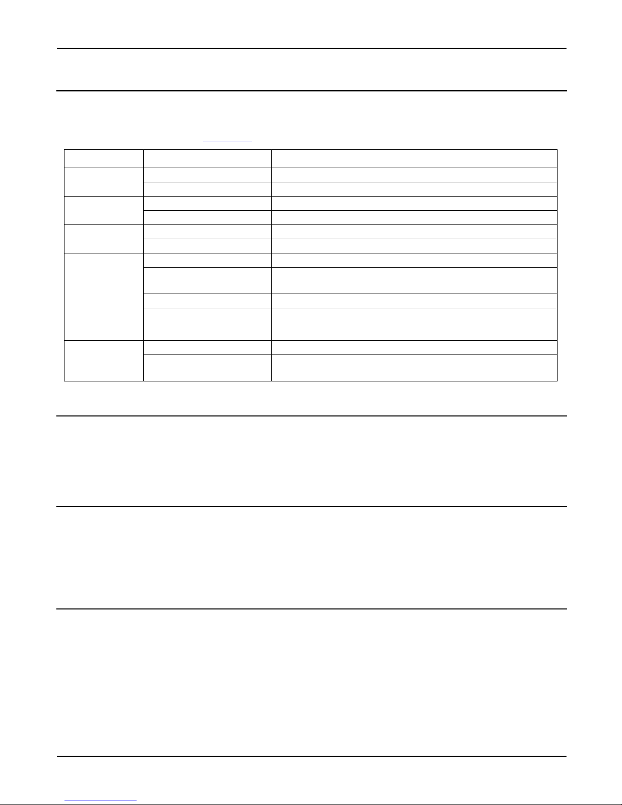
There are system diagnostic LEDs and Ethernet Port LEDs located on the front panel of the RocketLinx ES8108/ES8108F.
The LED indicators provide administrators with real-time system status. The following table describes the function of each
LED indicator Refer to the figure in Front Panel
LED Status Description
PWR1
PWR2
Alm
Port 1- 8
(RocketLinx
ES8108)
Port 1- 6
(RocketLinx
ES8108F)
Fiber port #7, #8
(RocketLinx
ES8108F)
Green on Power is on.
Off No power is being supplied.
Green on Power is on.
Off No power is being supplied.
Red on Port link down or power failure event occurred.
Off No event.
Link (Green on) A network device is detected and linked up.
Activity (Green blinks)
Speed (Yellow on/ 100Mbps) A network device is detected and link established at 100Mbps.
Speed (Yellow off) A network device is detected and link established at 10Mbps.
100Mbps Link (Green on) The port is operating in full-duplex mode.
100Mbps Activity (Green
Blinks)
on Page 7 for LED locations.
The port is transmitting or receiving packets from the connected
device.
The port is transmitting or receiving packets from the connected
device.
Packet Forwarding Ability
The RocketLinx ES8108/ES8108F features a packet filtering function for broadcast packet control protection and Quality of
Service (QoS). Both features can provide higher performance in a crowded network through traffic filtering and prioritization.
This subsection will introduce the principles of traffic control and forwarding precedence, including Broadcast control and
Quality of Service.
Broadcast Control
The RocketLinx ES8108/ES8108F begins to drop broadcast packets with DA (destination address) equal to
FF:FF:FF:FF:FF:FF if the received broadcast packets are more than the threshold – 198 packets/ per second at 100Mbps or 19
packets / per second at 10Mbps link speed.
All ports are enabled with this function by default to provide better network performance and prevent congestion caused by the
flooding of broadcast packets.
Quality of Service
The RocketLinx ES8108/ES8108F supports the frame type priority function, where high priority packets will be queued to a
high priority queue to share more bandwidth. The ratio of bandwidth of the high priority to the low priority queue is 8:1. After
8 high priority packets are processed, then 1 low priority packet is processed.
Both the RocketLinx ES8108 and RocketLinx ES8108F can examine the specific bits of VLAN Tag and TCP/IP TOS of IPv4
and IPv6.
8 - RocketLinx ES8108/ES8108F User Guide: 2000514 Rev. B LED Indicators
Page 9

Introduction
IPv4 Frame Format
IEEE 802.1Q tag based CoS
The RocketLinx ES8108/ES8108F checks the 3 bits of the priority field carried by a VLAN tag and maps it to the
corresponding priority. A packet with a priority field ranging from 0 to 3 will be treated as a low priority packet, and will be
stored in a low priority queue. A packet with a priority field ranging from 4 to 7 will be treated as a high priority packet, and
will be stored in the high priority queue.
IEEE 802.1Q Type of Service for IPv4 /IPv6 packet
The RocketLinx ES8108/ES8108F also provides the IP layer CoS (Class of Service) function by recognizing the priority octet
and mapping it to the corresponding priority. For an IPv4 packet, it is embedded in the TOS (Type of Service) Octet.
IEEE 802.1Q tag based CoS RocketLinx ES8108/ES8108F User Guide: 2000514 Rev. B - 9
Page 10

Introduction
IPv6 Frame Format
For an IPv6 data packet, the Traffic Class Octet is used to differentiate the Class of Service. When this function is enabled, the
RocketLinx ES8108/ES8108F will automatically recognize the IP version and capture either the TOS field (IPv4) or Traffic
Class field (IPv6) and distribute the packet into the High or Low Queue.
10 - RocketLinx ES8108/ES8108F User Guide: 2000514 Rev. B IEEE 802.1Q Type of Service for IPv4 /IPv6 packet
Page 11

Hardware Installation
Note: Do not connect to AC line - Neutral.
You can use the following subsections to install the RocketLinx ES8108/ES8108F:
• Connecting the Power and Ground
• Wiring the Relay Output on Page 12
• Enabling the Event Alarm
• Mounting the RocketLinx ES8108/ES8108F
• Connecting the Ethernet Ports
• Connecting the Fiber Port (RocketLinx ES8108F)
Connecting the Power and Ground
Use the following procedure to connect the power and the ground.
1. Insert the positive and negative wires (12-24AWG) into V+ and V- contacts.
2. Tighten the wire-clamp screws to prevent the wires from coming loose.
Note: Power should be disconnected from the power supply before connecting it to
the switch. Otherwise, your screwdriver blade can inadvertently short your
terminal connections to the grounded enclosure.
• PWR1 and PWR2 support power redundancy and reverse polarity protection.
• If both power inputs are connected, the RocketLinx ES8108/ES8108F is
powered from the highest connected voltage.
• The RocketLinx ES8108/ES8108F will emit an alarm if the ES8108/ES8108F is no longer receiving power.
• Positive and negative power system inputs are both accepted but PWR1 and PWR2 must apply the same mode.
on Page 12
on Page 13
on Page 13
on Page 14
3. Connect a ground wire between the chassis and earth ground using 12-24AWG wire to ensure that the RocketLinx
ES8108/ES8108F is not damaged by noise or electrical shock.
a. Loosen the earth ground screw (displayed in the previous illustration).
b. Tighten the screw after the earth ground wire is connected.
Hardware Installation RocketLinx ES8108/ES8108F User Guide: 2000514 Rev. B - 11
Page 12

Hardware Installation
Wiring the Relay Output
The RocketLinx ES8108/ES8108F have a built-in alarm-relay for port link and power events notifications. The relay contacts
are normally open and remain open when there is no failure event. The relay contacts will close when there is a failure event to
notify.
The failure events are selectable and enabled using the DIP switch on the ES8108/ES8108F. The relay contacts of RocketLinx
ES8108/ES8108F are rated for a maximum of 1A at 24VDC.
Wiring the alarm relay output is the same as wiring power inputs in Connecting the Power and Ground
.
1. Insert positive and negative wires into V+ and V-.
2. Tighten the wire-clamp screws to prevent the wires from coming loose.
Enabling the Event Alarm
You can use this subsection to configure and enable the event alarm to alert maintenance engineers once a system event has
occurred. The RocketLinx ES8108/ES8108F is equipped with one dry relay output for port link failure or power failure.
On the bottom of the ES8108/ES8108F, there is one 9-pin DIP switch for alarm control. If you connect the alarm (Wiring the
Relay Output on Page 12) and set the DIP switch of the intended Alarm to ON, the relay output forms a short circuit if an alarm
occurs.
Use this table to set the DIP switch for the relay output alarm.
Pin Status Description
On Enables the port link down alarm for the corresponding port.
1-8
Off Disables the port link down alarm on the corresponding port.
On Enables the power failure alarm.
P9
Off Disables the power failure alarm.
12 - RocketLinx ES8108/ES8108F User Guide: 2000514 Rev. B Wiring the Relay Output
Page 13
Hardware Installation
Switch
3 TD+
6 TD-
1 RD+
2 RD-
3 RD+
6 RD-
1 TD+
2 TD-
Router or PC
Switch
3 TD+
6 TD-
1 RD+
2 RD-
3 TD+
6 TD-
1 RD+
2 RD-
Switch
Straight-Through Cabling Crossover Cabling
Mounting the RocketLinx ES8108/ES8108F
You can mount the RocketLinx ES8108/ES8108F on a DIN rail or mounted to the wall. The DIN rail clip is already attached to
the RocketLinx ES8108/ES8108F when packaged.
Note: The RocketLinx ES8108/ES8108F will disperse heat through the metal case during PoE port operation. The
RocketLinx ES8108/ES8108F should be installed and mounted onto a panel which provides good heat dispersion.
You can use this procedure to mount the ES8108/ES8108F on a DIN rail.
1. Insert the upper end of DIN rail clip into the back of DIN rail track from its
upper side.
2. Lightly push the bottom of DIN rail clip into the track.
3. Ensure the DIN rail clip is tightly attached on the track.
4. To remove the RocketLinx ES8108/ES8108F from the track, reverse the steps
above.
To mount the ES8108/ES8108F on the wall:
1. Snap the DIN rail plate into the track.
2. Attach the ES8108/ES8108F to the wall using the mounting screws.
Connecting the Ethernet Ports
You can use the following information to connect standard Ethernet cables between the RocketLinx ES8108/ES8108F 10/
100BASE-TX Ethernet ports and the network nodes. The Fast Ethernet ports support 10BASE-T and 100BASE-TX, full- or
half-duplex modes.
All the Fast Ethernet ports automatically detect the signal from the connected devices to negotiate the link speed and duplex
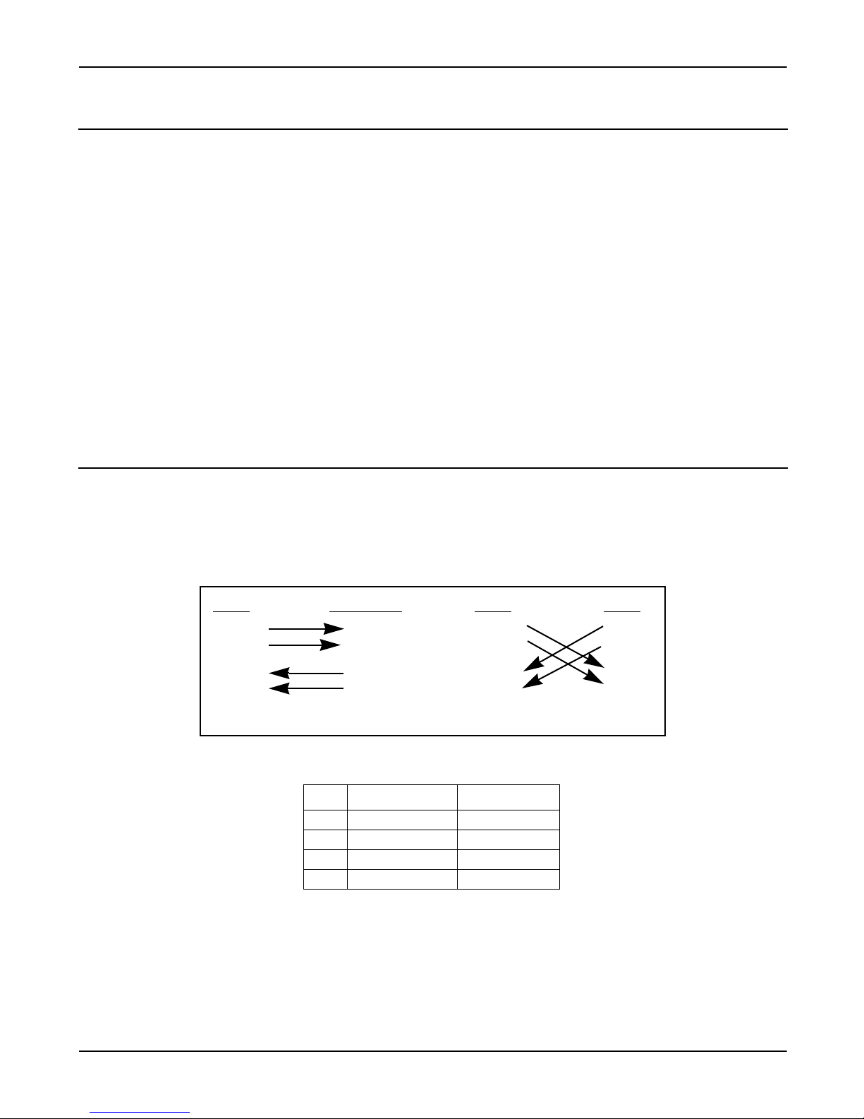
mode. Auto MDI/MDIX allows you to connect another switch, hub, or workstation without changing straight-through or
crossover cables. Crossover cables cross-connect the transmit lines at each end to the received lines at the opposite end.
The Ethernet cables use Pins 1, 2, 3, and 6 of an 8-pin RJ45 connector. The signals of these pins are converted by the automatic
MDIX function, as shown in the following table.
Pin MDIX Signals MDI Signals
1RD+ TD+
2RD- TD-
3TD+ RD+
6TD- RD-
Connect one side of an Ethernet cable into any switch port and connect the other side to your attached device. The LINK/ACT
LED is lit when the cable is correctly connected. Always make sure that the cables between the switches and attached devices
(for example, switch, hub, or workstation) are less than 100 meters (328 feet).
The wiring cable types and maximum cable length are as follows.
• 10BASE-T: 2-pair UTP/STP Category 3, 4, 5 cable, EIA/TIA-568 100-ohm (100 meters)
• 100BASE-TX: 2-pair UTP/STP Category 5 cable, EIA/TIA-568 100-ohm (100 meters)
Mounting the RocketLinx ES8108/ES8108F RocketLinx ES8108/ES8108F User Guide: 2000514 Rev. B - 13
Page 14
Hardware Installation
Caution
This is a Class 1 Laser/LED product.
Do not stare into the Laser/LED beam.
Connecting the Fiber Port (RocketLinx ES8108F)
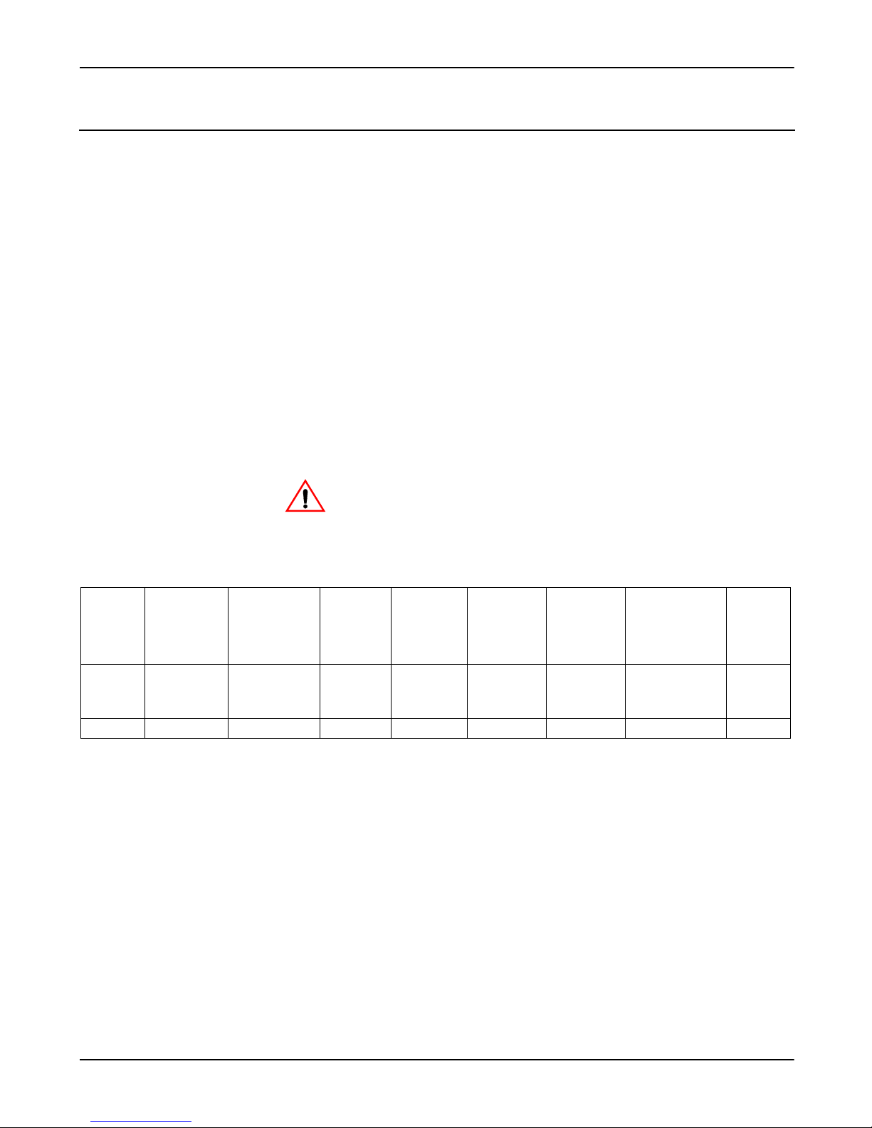
Connect the fiber port on the RocketLinx ES8108F to another fiber Ethernet device using the following information.
A wrong connection will cause the fiber port not to work properly.
The fiber connector is a standard connector or square connector (SC).
Min. Launch
Power –Max.
Receive
Sensitivity
Distance
(km)
2km
Note
(below)
Mode Cable Type Wavelength
Multi
50/125um
62.5/125um
1310nm -20dBm -14dBm -31dBm 0dBm 11dBm
Transmit
Power
(min.)
Transmit
Power
(max.)
Receive
Sensitivity
(max.)
Receive
Sensitivity
(min.)
Single 8-10/125um 1310nm -15dBm -8dBm -34dBm -8dBm 19dBm 30km
Note: In the IEEE standard, it suggests the available transmission distance is 2KM for 62.5/125um fiber optical cable in
1310nm wave length. Actually, the attenuation of Multi-Mode 62.5/125um optical fiber cable is 1.5dBm/km and the
maximum link distance can up to 4 to 5km.
14 - RocketLinx ES8108/ES8108F User Guide: 2000514 Rev. B Connecting the Fiber Port (RocketLinx ES8108F)
Page 15

IEEE organization recommends maximum optical fiber cable distances as defined in the following table.
Hardware Installation
Standard
Data Rate
(Mbps)
Cable T y pe
10BASE-FL 10 850nm, 50/125um or 62.5/125um
Multi-Mode optical fiber cable
100BASE-FX 100 1310nm, 50/125um or 62.5/125um
Multi-Mode optical fiber cable
100BASE-SX 100 850nm, 50/125um or 62.5/125um
Multi-Mode optical fiber cable
1000BASE-SX 1000 850nm, 50/125um
Multi-mode optical fiber cable
850nm, 62.5/125um
Multi-Mode optical fiber cable
1000BASE-LX 1000 1310nm, 50/125um or 62.5/125um
Multi-mode optical fiber cable
1310nm, 9/125um
Single-Mode optical fiber cable
1000BASE-LH 1000 1550nm,9/125um
Single-Mode optical fiber cable
IEEE Standard
Distance
2km
2km
300m
550m
220m
550m
5km
70km
Connecting the Fiber Port (RocketLinx ES8108F) RocketLinx ES8108/ES8108F User Guide: 2000514 Rev. B - 15
Page 16

Hardware Installation
16 - RocketLinx ES8108/ES8108F User Guide: 2000514 Rev. B Connecting the Fiber Port (RocketLinx ES8108F)
Page 17
Troubleshooting and Technical Support
Troubleshooting
If you are having problems, you may want to check the following:
• Make sure you are using the correct DC power supplies (12 to 48VDC). Do not use power supplies with DC output over
48VDC.
• Select Ethernet cables with specifications suitable for your applications to set up your systems.
Ethernet cables are categorized into unshielded twisted-pair (UTP) and shielded twisted-pair (STP) cables.
Category 3, 4, 5, and 6 Ethernet cables are suitable for systems with 10 Mbps transmission speed.
For systems with 100 Mbps transmission speed, Category 5 and 6 Ethernet cables are the only suitable specifications for
this environment.
You also need to make sure that the distance between any two nodes does not exceed 100 meters (328 feet).
•If the Power LEDs go off when the power cord is plugged in, a power failure might have occurred. Check the power
output connection to see if there is any error at the power source. If you still cannot solve the problem, contact Comtrol
Technical Support for assistance.
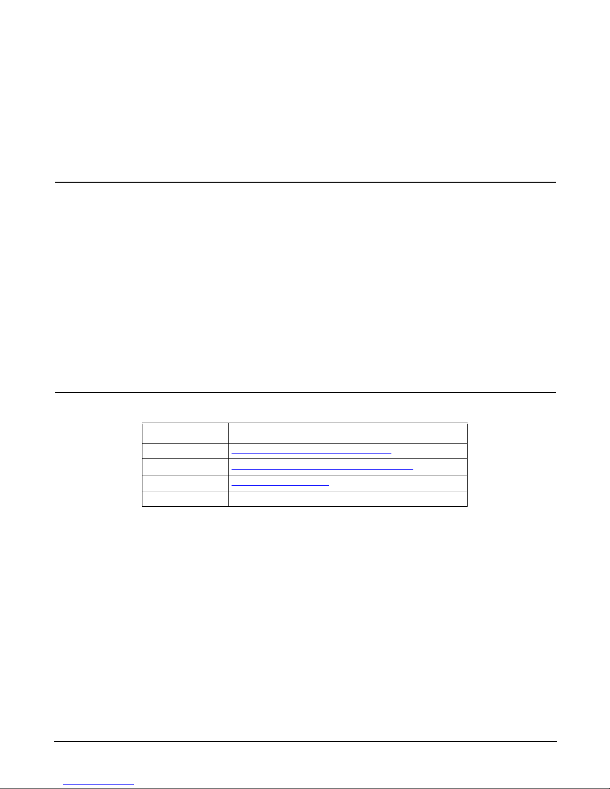
Comtrol Support
You can use one of the following methods to contact Comtrol.
Contact Method Web Address or Phone Number
Support http://www.comtrol.com/pub/en/support
Downloads ftp://ftp.comtrol.com/html/ES8108.htm
Web Sit e http://www.comtrol.com
Phone 763.494.4100
Troubleshooting and Technical Support RocketLinx ES8108/ES8108F User Guide: 2000514 Rev. B - 17
Page 18

Troubleshooting and Technical Support
18 - RocketLinx ES8108/ES8108F User Guide: 2000514 Rev. B Comtrol Support
Page 19

Index
Numerics
100BASE-TX 13
10BASE-T 13
C
cables
Fast Ethernet
D
Downloads 17
E
Ethernet 13
F
Fast Ethernet port
cables
13
H
hardware installat io n 11
13
I
installation
hardware
Phone 17
support 17
technical support 17
Web Site 17
11
P
S
T
W
Index
RocketLinx ES8108/ES8108F User Guide: 2000514 Rev. B - 19
Page 20

Index
20 - RocketLinx ES8108/ES8108F User Guide: 2000514 Rev. B Index
 Loading...