

Page 1

RocketLinx ES7528
Industrial Rack Mount
Managed Switch
24-Port PoE/PoE Plus Ports
4 Combo RJ45/SFP Gigabit Ports
User Guide
2000509 Rev A
Page 2

Copyright Notice
Document Number: 2000509 Rev A
Comtrol and RocketLinx are trademarks of Comtrol Corporation.
Microsoft and Windows are trademarks of Microsoft Corporation.
FireFox is a trademark of Mozilla Foundation.
PuTTY is a copyright of Simon Tatham.
Other product names mentioned herein may be trademarks and/or registered trademarks of their respective owners.
First Edition, February 9, 2011
Copyright © 2010 - 2011. Comtrol Corporation.
All Rights Reserved.
Comtrol Corporation makes no representations or warranties with regard to the contents of this document or to the
suitability of the Comtrol product for any particular purpose. Specifications are subject to change without notice.
Some software or features may not be available at the time of publication. Contact your reseller for current product
information.
Federal Communications Commission (FCC) Statement
This equipment has been tested and found to comply with the limits for a Class A digital device, pursuant to Part 15
of the FCC Rules. These limits are designed to provide reasonable protection against harmful interference when the
equipment is operated in a commercial environment. This equipment generates, uses, and can radiate radio frequency
energy and, if not installed and used in accordance with the instruction manual, may cause harmful interference to
radio communications. Operation of this equipment in a residential area is likely to cause harmful interference in
which case the user will be required to correct the interference at his expense.
The user is cautioned that changes and modifications made to the equipment without approval of the manufacturer
could void the user's authority to operate this equipment.
Page 3

Table of Contents
Introduction .................................................................................................................................................................................7
Overview ...............................................................................................................................................................................7
Major Features.....................................................................................................................................................................7
Hardware Installation.................................................................................................................................................................9
Connect the Power .................................................... ...........................................................................................................9
Mount the RocketLinx ES7528.........................................................................................................................................10
Connect 10/100BASE-TX Ports........................................................................................................................................11
Connect Gigabit Ports (Combo Ports 25-28)...................................................................................................................12
Connect SFP Transceivers (Combo Ports 25-28)............................................................................................................12
Connect the Digital or Relay Output................................................................................................................................12
Panel Layout........ ..................................................................................... ..........................................................................13
Preparation for Management...................................................................................................................................................15
Programming Network Information Using NetVision ...................................................................................................15
Using a Web Interface....................................... .................................................................................................................16
Web Interface................................................................................................................................................................16
Secure Web Interface ....................................................................................................................................................17
Using the Command Line Interface (CLI).......................................................................................................................19
Using the Serial Console...............................................................................................................................................19
Using a Telnet Console .................................................................................................................................................21
Telnet......................................................................................................................................................................21
SSH Client .............................................................................................................................................................21
Feature Configuration...............................................................................................................................................................23
Command Line Interface Introduction............................................................................................................................23
User EXEC Mode .........................................................................................................................................................24
Privileged EXEC Mode ................................................................................................................................................24
Global Configuration Mode ..........................................................................................................................................25
(Port) Interface Configuration.......................................................................................................................................26
(VLAN) Interface Configuration ..................................................................................................................................27
Basic Setting ........................................................................................................................................................................29
Switch Setting ...............................................................................................................................................................29
Admin Password ...........................................................................................................................................................30
IP Configuration............................................................................................................................................................30
Time Setting..................................................................................................................................................................31
Jumbo Frame ................................................................................................................................................................34
DHCP Server Configuration .........................................................................................................................................35
DHCP Leased Entries ...................................................................................................................................................36
DHCP Relay Agent.......................................................................................................................................................37
Backup and Restore ......................................................................................................................................................38
Firmware Upgrade ........................................................................................................................................................39
Factory Defaults.................................................................................................................
System Reboot ..............................................................................................................................................................41
CLI Commands for Basic Setting .................................................................................................................................42
...........................................40
RocketLinx ES7528 Industrial Managed PoE Rack Mount User Guide: 2000509 Rev. A - 3
Page 4

Table of Contents
Port Configuration.............................................................................................................................................................47
Port Control...................................................................................................................................................................47
Port Status .....................................................................................................................................................................49
Rate Control ..................................................................................................................................................................50
Storm Control................................................................................................................................................................51
Port Trunking ................................................................................................................................................................52
Aggregation Setting ...............................................................................................................................................52
Aggregation Status.................................................................................................................................................53
Command Lines for Port Configuration .......................................................................................................................54
Power over Ethernet ................................................................................ ..........................................................................58
Emergency Power Management ...................................................................................................................................58
PoE Control...................................................................................................................................................................58
PD Status Detection ......................................................................................................................................................60
PoE Scheduling .............................................................................................................................................................61
PoE Status .....................................................................................................................................................................61
Command Line for PoE Control .. ................................................................................................................................62
Network Redundancy ........................................................................................................................................................69
RSTP .............................................................................................................................................................................69
RSTP Information .........................................................................................................................................................71
Redundant Ring.............................................................................................................................................................72
Redundant Ring Information ........................................................................................................................................74
Command Lines for RSTP............................................................................................................................................75
VLAN...................................................................................................................................................................................79
VLAN Port Configuration ............................................................................................................................................80
VLAN Configuration ....................................................................................................................................................81
GVRP Configuration.....................................................................................................................................................83
VLAN Table .................................................................................................................................................................84
CLI Commands for the VLAN .....................................................................................................................................85
Traffic Prioritization..........................................................................................................................................................88
QoS Setting ...................................................................................................................................................................89
CoS-Queue Mapping.....................................................................................................................................................90
DSCP-Queue Mapping .................................................................................................................................................91
CLI Commands of the Traffic Prioritization.................................................................................................................92
Multicast Filtering..............................................................................................................................................................95
IGMP Snooping ............................................................................................................................................................96
IGMP Query..................................................................................................................................................................97
Unknown Multicast.......................................................................................................................................................97
GMRP Configuration....................................................................................................................................................98
CLI Commands for Multicast Filtering ........................................................................................................................99
SNMP.................................................................................................................................................................................101
SNMP Configuration .............................................................................................................
SNMP V3 Profile
........................................................................................................................................................102
.....................................101
SNMP Traps................................................................................................................................................................103
CLI Commands for SNMP .........................................................................................................................................104
Security..............................................................................................................................................................................105
Filter Set (Access Control List) ..................................................................................................................................105
MAC Filter (Port Security) ..................................................................................................................................107
IP Filter ................................................................................................................................................................109
Filter Attach .........................................................................................................................................................111
802.1x Configuration ..................................................................................................................................................112
802.1x Port Configuration...........................................................................................................................................113
802.1x Port Status .......................................................................................................................................................114
CLI Commands for Security.......................................................................................................................................115
4 - RocketLinx ES7528 Industrial Managed PoE Rack Mount User Guide: 2000509 Rev. A Table of Contents
Page 5

Table of Contents
Warning.............................................................................................................................................................................117
Fault Relay ..................................................................................................................................................................117
Event Selection ...........................................................................................................................................................120
SysLog Configuration .................................................................................................................................................122
SMTP Configuration...................................................................................................................................................123
CLI Commands for Warnings.....................................................................................................................................124
Monitor and Diag.............................................................................................................................................................127
MAC Address Table ...................................................................................................................................................127
Port Statistics...............................................................................................................................................................128
Port Mirroring .............................................................................................................................................................129
Event Log....................................................................................................................................................................130
Topology Discovery (LLDP) ......................................................................................................................................131
Ping Utility..................................................................................................................................................................132
CLI Commands of the Monitor and Diag ...................................................................................................................133
Device Front Panel...........................................................................................................................................................136
Save to Flash.................................................................... .................................................................................................137
Command Lines for Saving to Flash...........................................................................................................................137
Logout................................................................................................................................................................................137
Command Lines for Logging Out...............................................................................................................................137
Technical Support ...................................................................................................................................................................139
Comtrol SFP Modules......................................................................................................................................................139
Comtrol Private MIB.......................................................................................................................................................139
Comtrol Support ..............................................................................................................................................................139
Index.........................................................................................................................................................................................141
Table of Contents RocketLinx ES7528 Industrial Managed PoE Rack Mount User Guide: 2000509 Rev. A - 5
Page 6

Table of Contents
6 - RocketLinx ES7528 Industrial Managed PoE Rack Mount User Guide: 2000509 Rev. A Table of Contents
Page 7

Introduction
Overview
The RocketLinx ES7528 is a rack mount high-port density managed PoE switch designed exclusively for highly critical PoE
applications such as real-time IP video surveillance with high-resolution quality and evolving wireless communication systems
such as Wimax and 802.11 a/b/g/n access points.
The RocketLinx ES7528 provides a total of 28-ports:
• 24 Fast Ethernet PoE injector ports that can deliver 15.4 Watts (IEEE 802.3af) or 32 Watts (high power PoE IEEE 802.3at)
• 4 gigabit copper/SFP combo uplink Ethernet ports
With network redundancy technology, the RocketLinx ES7528 can aggregate up to twelve Fast Ethernet and two gigabit rings
while providing high-quality data transmission with less than 5ms network recovery time. To ensure traffic switching without
data loss and blocking, the RocketLinx ES7528 provides a 12.8G backplane with an integrated non-blocking switching
function. The RocketLinx ES7528 incorporates LLDP functionality and works with NetVision to allow administrators to
automatically discover devices and efficiently manage the industrial network performance in large-scale surveillance
networks. The RocketLinx ES7528 supports AC and dual 53VDC power inputs that can be aggregated to provide redundancy.
The RocketLinx ES7528 also provides alarm relay output signaling functionality.
The RocketLinx ES7528 provides advanced Layer 2 management features including IGMP Query/Snooping, DHCP, 256
VLAN, QoS, LACP, LPLD, and the corrosion resistant robust design, the RocketLinx ES7528 is a revolutionary solution for
industrial surveillance applications.
Major Features
The RocketLinx ES7528 has the following features:
• 24 10/100BASE-TX and four gigabit copper/SFP combo uplink ports
• 24 ports that support both IEEE 802.3af (compliant 15.4W) and IEEE 802.3at (compliant 32W), including two-event and
LLDP classification
• Flexible-bandwidth and long-distance data transmission by SFP transceivers
• Total power budget of up to 720W
• Operating temperature range of -25° to 65°C
• LPLD (Link Partner Live Detect Function) for reliable PoE connection through active powered device status detection and
auto reset function
• 12.8G Non-Blocking backplane, 16K MAC table for wire speed bidirectional switching
• IEEE 1588 PTP compliance for precise time synchronization
• Network redundancy technology for aggregating up to 12 x 100Mb plus two gigabit rings
• Supports up to 9,216 bytes jumbo frame for secured large file transmission
• IEEE 802.1AB LLDP and optional NetVision software for auto-topology and large network group management
• IGMP Query v1/v2 & snooping v1/v2/v3 for advanced multicast filtering
• Up to 256 VLAN traffic isolation
• Advanced network management features support SNMP, RMON
• Supports DHCP client/server, DHCP Option 82 for automatic IP configuration
• Dual redundant AC and DC power inputs with a wide voltage range
• IP31 rugged metal case with great heat dispersion
Detailed specifications are available for the RocketLinx ES7528 data sheet, which is available on the Comtrol web site
.
Introduction RocketLinx ES7528 Industrial Managed PoE Rack Mount User Guide: 2000509 Rev. A - 7
Page 8

Introduction
8 - RocketLinx ES7528 Industrial Managed PoE Rack Mount User Guide: 2000509 Rev. A Major Features
Page 9
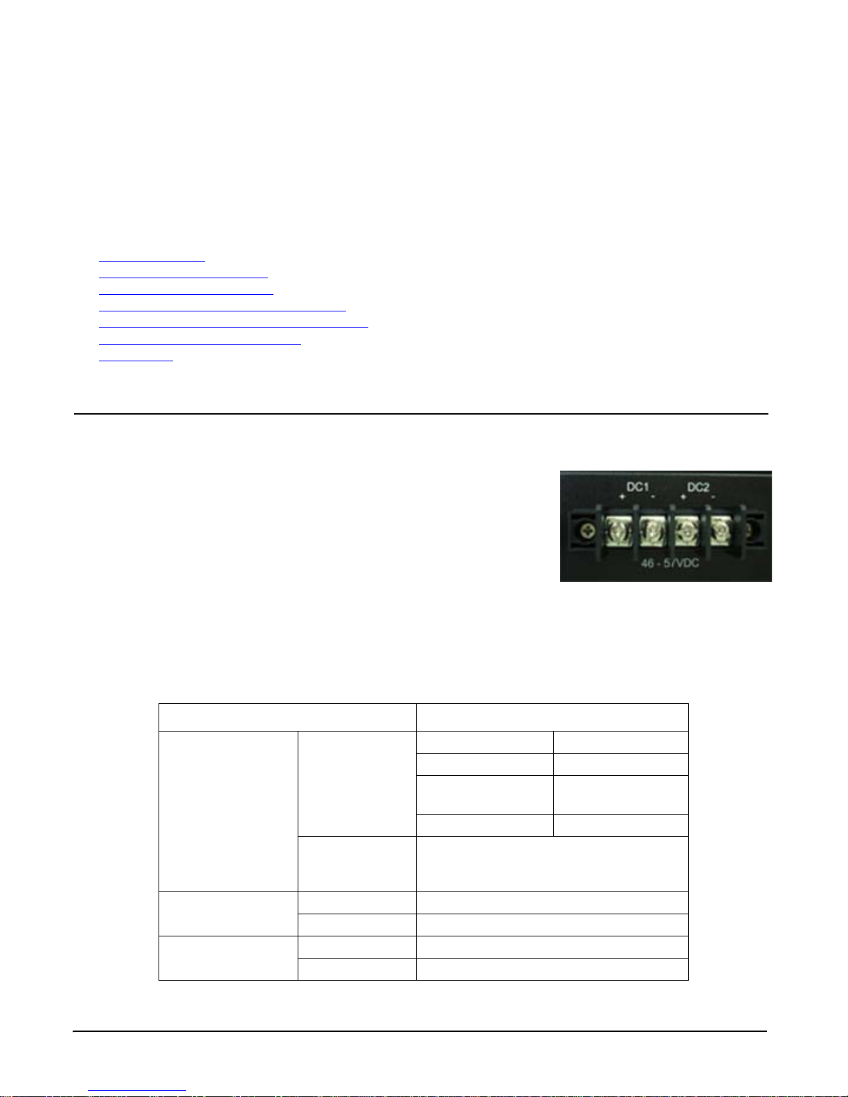
Hardware Installation
Wire: 12 to 22 AWG
DC Input: 53VDC
You can use the following subsections to install the RocketLinx ES7528:
• Connect the Power
• Mount the RocketLinx ES7528 on Page 10
• Connect 10/100BASE-TX Ports
• Connect Gigabit Ports (Combo Ports
• Connect SFP Transceivers (Combo Ports
• Connect the
• Panel Layout
Digital or Relay Output on Page 12
on Page 13
Connect the Power
You can use the following procedure to connect power to the RocketLinx ES7528. The RocketLinx ES7528 is equipped with
both AC and/or DC1/DC2 power inputs.
The RocketLinx ES7528 provides redundant or aggregated power inputs (AC and/or
DC1/2). DC1 and DC2 inputs support reverse polarity protection. The RocketLinx
ES7528 will signal an alarm for loss of power on either DC1 or DC2.
1. Connect the power cord to the AC power input connector.
on Page 11
25-28) on Page 12
25-28) on Page 12
Note: To reach the maximum total power budget, power inputs must be
2. Connect the DC power inputs.
Note: Power should be disconnected from the power supply before connecting it
a. Insert positive and negative wires into V+ and V- contacts.
b. Tighten the wire-clamp screws to prevent the wires from coming loose.
This table provides power supply specifications for the RocketLinx ES7528.
aggregated. Refer to the following table for detailed information.
to the switch. Otherwise, your screwdriver blade can inadvertently short
your terminal connections to the grounded enclosure.
Electrical Specifications Value
802.3af 48VD C (46-57VDC)
802.3at 53VD C (50-57VDC)
Power Input Voltage
PoE Output Voltage
Maximum PoE
Power/Port
DC1/DC2
PSU/AC power
802.3af 44-57VDC
802.3at 50-57VDC
802.3af 15.4W
802.3at 32W
AC and DC1/DC2
aggregated
DC1/DC2 aggregated DC1=DC2†
100-250VAC
47~63Hz
4A
53VDC
8.2A maximum
Hardware Installation RocketLinx ES7528 Industrial Managed PoE Rack Mount User Guide: 2000509 Rev. A - 9
Page 10

Hardware Installation
Temperature: Verify that the rack environment temperature conforms to the specified operating
temperature range. If necessary, refer to the Comtrol web site for operating temperature ranges.
Mechanical Loading: Do not place any equipment on top of the switch. In a high vibration
environment, additional rack mounting protection is necessary.
Grounding: Rack-mounted equipment should be properly grounded. On the back panel of the
RocketLinx ES7528, there is one earth ground screw. Loosen the earth ground screw with a
screwdriver; then tighten the screw after earth ground wire is connected.
Electrical Specifications (cont.) Value
DC1 400W
Power Budget
Total Power Budget
Power Consumption Maximum 28W without PD load
† The RocketLinx ES7528 provides redundant or aggr egated power inputs, depending on the
voltage of the power input. If there are more than two power inputs connected with
different voltages, the RocketLinx ES7528 is powered from the highest connected voltage
(redundant power). If the voltages of power inputs are the same, the total power output is
aggregated.
For example, to reach 700W, you can aggregate the power inputs accordingly:
• AC = 300W and DC1/2=400W
• DC1 = 350W and DC2/ = 350W
DC2 400W
PSU/AC power 300W
Minimum Up to 568W
Maximum Up to 720W
Mount the RocketLinx ES7528
You can use the following procedure to mount the RocketLinx ES7528 into a rack.
1. Attach the brackets to the RocketLinx ES7528 by using the screws provided in the rack mount kit.
2. Mount the RocketLinx ES7528 in a 19-inch rack by using the four rack-mounting screws provided in the kit.
Note: When installing multiple switches in high temperature environments, reserve 0.5U-1U of free space between the
switches. It is important to disperse the heat generated by the RocketLinx ES7528.
10 - RocketLinx ES7528 Industrial Managed PoE Rack Mount User Guide: 2000509 Rev. A Mount the RocketLinx ES7528
Page 11
Hardware Installation
Switch
3 TD+
6 TD-
1 RD+
2 RD-
3 RD+
6 RD-
1 TD+
2 TD-
Router or PC
Switch
3 TD+
6 TD-
1 RD+
2 RD-
3 TD+
6 TD-
1 RD+
2 RD-
Switch
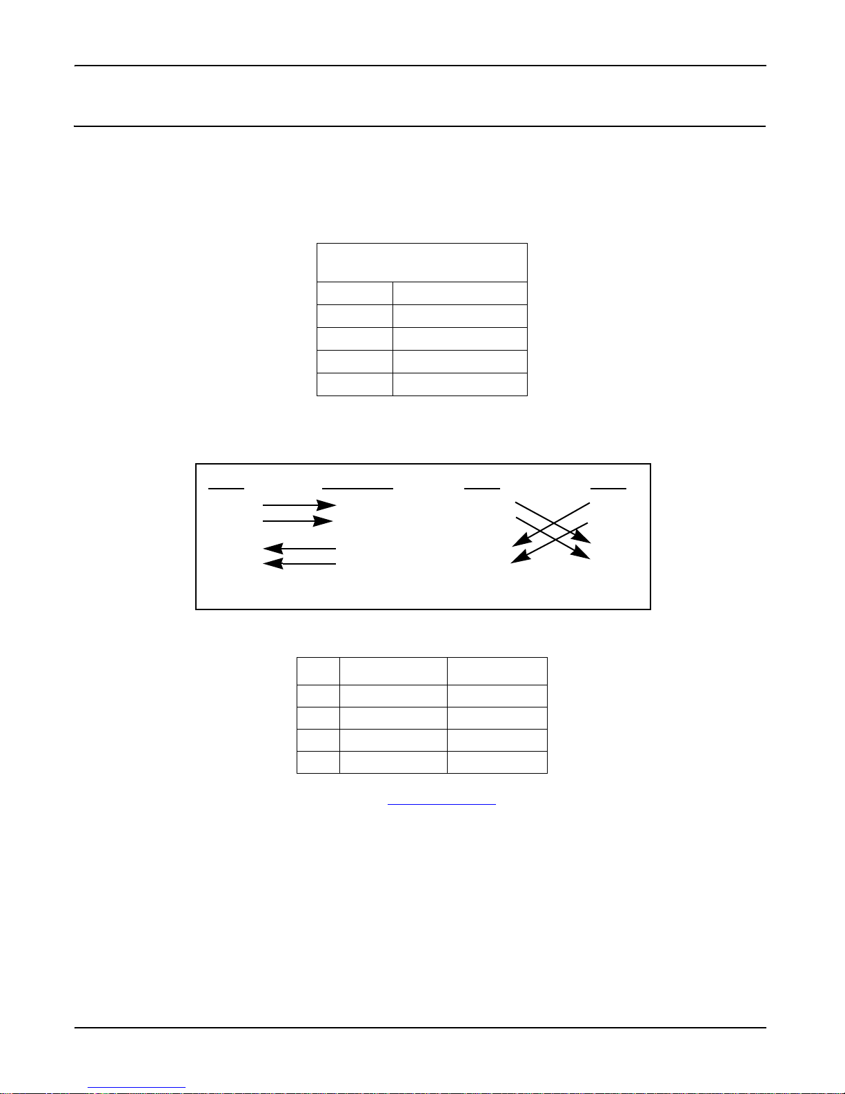
Straight-Through Cabling Crossover Cabling
Connect 10/100BASE-TX Ports
You can use the following information to connect standard Ethernet cables between the RocketLinx ES7528 10/100BASE-TX
Ethernet ports and the network nodes.
Ports 1-24 are Fast Ethernet 10/100BASE-TX ports that are IEEE802.3af (PoE) and IEEE802.3at (PoE Plus) compliant. In
addition to the 10/100BASE-TX port features, the PoE ports can provide 48VDC at 350mA (maximum 15.4W/port) or provide
53VDC at 606mA (maximum 32W/port), auto-sensing and automatic power off when cables are removed. The following table
shows the RJ45 PoE pin-out assignment.
10/100BASE-TX PoE Pin-Out
1 RX + and Vport -
2 RX - and Vport -
3 TX + and Vport +
6 TX - and Vport +
4, 5, 7, 8 NC
The Fast Ethernet ports support 10BASE-T and 100BASE-TX, full- or half-duplex modes. All the Fast Ethernet ports autodetect the signal from connected devices to negotiate the link speed and duplex mode. Auto MDI/MDIX allows you to connect
another switch, hub, or workstation without changing straight-through or crossover cables. Crossover cables cross-connect the
transmit lines at each end to the received lines at the opposite end.
The Ethernet cables use Pins 1, 2, 3, and 6 of an 8-pin RJ45 connector. The signals of these pins are converted by the automatic
MDIX function, as shown in the following table.
Pin Signals MDI Signals
1RD+ TD+
2RD- TD-
3TD+ RD+
6TD- RD-
Connect one side of an Ethernet cable into any switch port and connect the other side to your attached device. The LNK LED
lights up when the cable is correctly connected. Refer to Device Front Panel
on Page 136 for descriptions of each LED
indicator. Always make sure that the cables between the switches and attached devices (for example, switch, hub, or
workstation) are less than 100 meters (328 feet).
The wiring cable types are as follows.
• 1000BASE-TX: 4-pair UTP/STP Category 5 cable, EIA/TIA-568 100-ohm (100m)
• IEEE 802.3af: 4-pair UTP/STP Category 5 cable, EIA/TIA-568 100-ohm (100m)
• IEEE 802.3at: 4-pair UTP/STP Category 5e / 6 cable, EIA/TIA-568 100-ohm (100m)
Connect 10/100BASE-TX Ports RocketLinx ES7528 Industrial Managed PoE Rack Mount User Guide: 2000509 Rev. A - 11
Page 12
Hardware Installation
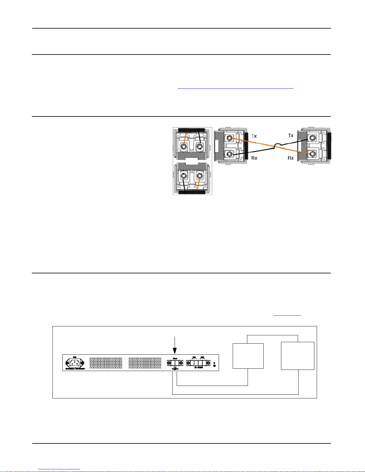
The SFP cage is 2 x1 design.
Digital Output (Relay) 1A/24VDC
Power
Source
Alarm/
PLC Input
-
+
Ground the chassis to earth ground
Wire: 12 to 22 AWG
Connect Gigabit Ports (Combo Ports 25-28)
Connect the appropriate network cables between the RocketLinx ES7528 Combo 1000BASE-TX (gigabit)/SFP ports (Auto
MDI/MDIX) and the network. The RocketLinx ES7528 includes four RJ45 gigabit Ethernet ports (Ports 25-28). The gigabit
Ethernet ports support 10BASE-T, 100BASE-TX, and 1000BASE-TX.
The gigabit ports are combo ports with SFP Ports 25-28. See Connect SFP Transceivers (Combo Ports
about combo port functionality.
25-28) for information
Connect SFP Transceivers (Combo Ports 25-28)
Optionally, connect SFP transceivers. Comtrol
recommends using Comtrol gigabit SFP transceivers.
The RocketLinx ES7528 equips four gigabit SFP ports
combined with gigabit Ethernet ports. The SFP ports
accept standard mini GBIC SFP transceivers that support
1000BASE-SX/LX/LHX/XD/ZX. To ensure system
reliability, Comtrol recommends using a Comtrol
certified gigabit SFP Transceiver. The certified SFP
transceiver includes 1000BASE-SX/LX single/multi
mode range from 550m to 80km.
1. Plug the SFP transceiver into the SFP fiber
transceiver.
2. Connect the transmit channel to the receive channel at each end.
3. Check the direction/angle of the fiber transceiver and the fiber cable.
Note: This is a Class 1 Laser/LED product. Don’t stare at the Laser/LED Beam.
The SFP port does not function until the fiber cable is linked to another active device. The SFP and corresponding RJ45 ports
work in an exclusive mode. Traffic sent or received through the SFP module has priority thus no traffic is sent or received over
the corresponding RJ45 connection. To use the RJ45 connection, remove the corresponding SFP.
Connect the Digital or Relay Output
If desired, connect the Digital or Relay Output. The relay contacts are energized, (open) for normal operation and close for
fault conditions. The fault conditions include:
• Power failure
• Ethernet port link break
• Other pre-defined events, which you can configure in the RocketLinx ES7528 user interface. See Fault Relay
for detailed information.
1. Insert positive and negative wires into V+ and V-.
2. Tighten the wire-clamp screws to prevent the wires from coming loose.
on Page 117
12 - RocketLinx ES7528 Industrial Managed PoE Rack Mount User Guide: 2000509 Rev. A Connect Gigabit Ports (Combo Ports 25-28)
Page 13
Hardware Installation
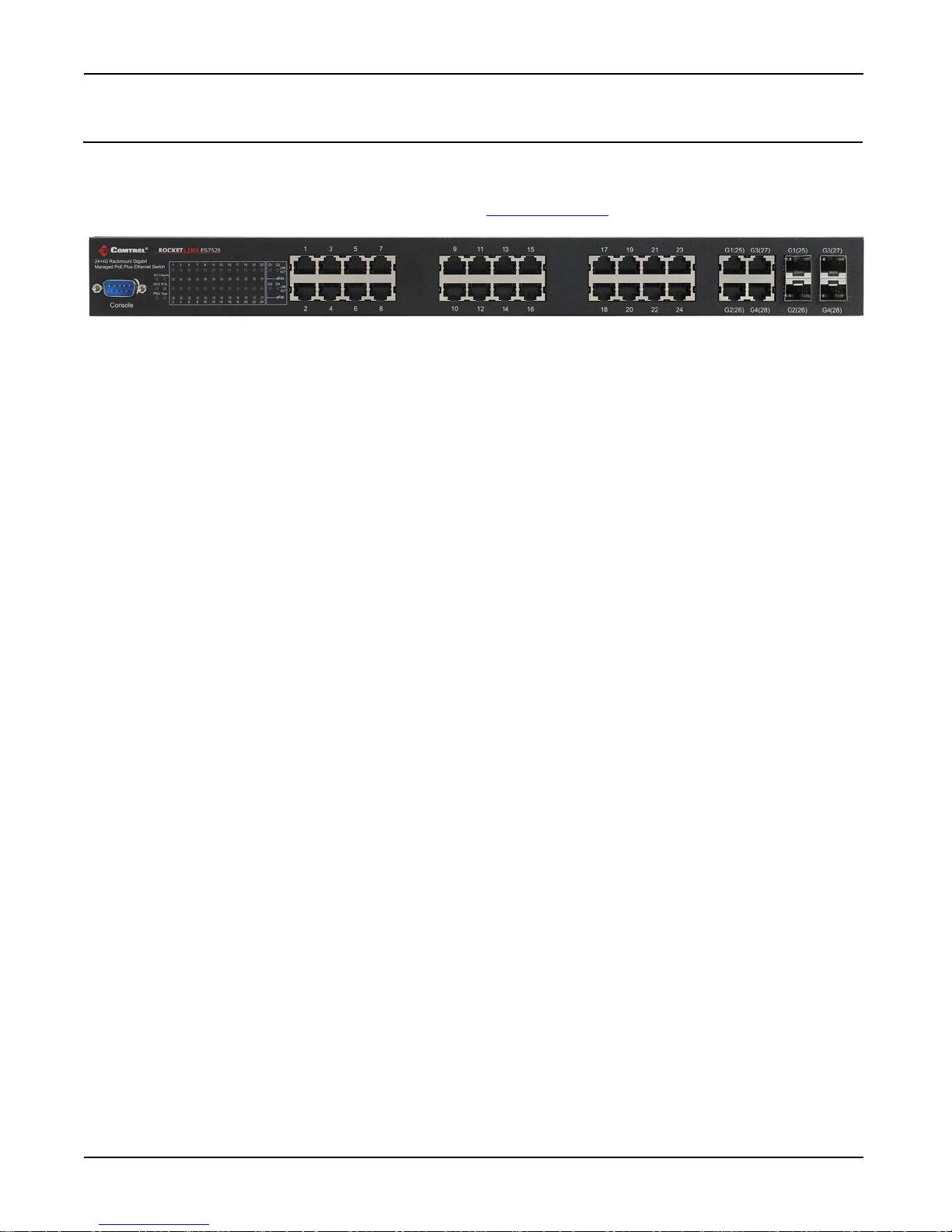
Panel Layout
The front panel includes up to 24 10/100BASE-TX Ethernet ports, four combo gigabit Ethernet ports, SFP slot, RS-232
console port, System / Combo Port LED and 24 PoE LEDs.
The web interface provides a remote view of the LEDs. Refer to Device Front Panel
on Page 136.
Panel Layout RocketLinx ES7528 Industrial Managed PoE Rack Mount User Guide: 2000509 Rev. A - 13
Page 14

Hardware Installation
14 - RocketLinx ES7528 Industrial Managed PoE Rack Mount User Guide: 2000509 Rev. A Panel Layout
Page 15

Preparation for Management
The RocketLinx ES7528 provides both in-band and out-band configuration methods:
• Out-band management means that you configure the RocketLinx ES7528 using the RS-232 console cable and the
Command Line Interface (CLI) to access the RocketLinx ES7528 without attaching an admin PC to the network. You can
also use out-band management, if you lose the network connection to the RocketLinx ES7528.
• In-band management means that you connect remotely using the RocketLinx ES7528 IP address through the network. You
can remotely connect with the RocketLinx ES7528 embedded Java applet web interface or a Telnet console and the CLI.
If you are planning on using in-band management, you need to program the RocketLinx ES7528 IP address to meet your
network requirements. The easiest way to configure the IP address is using a Windows system and NetVision.
The following topics are covered in this section:
• Programming Network Information Using NetVision
• Using a Web Interface on Page 16
• Using the Command Line Interface (CLI)
Programming Network Information Using NetVision
You can use the following recommended procedure to program the network information into the RocketLinx ES7528.
Optionally, you can use the Command Line Interface (CLI), web browser, or telnet to program the network information into
the RocketLinx ES7528. Refer to the following subsections for other configuration methods.
1. If necessary, install the latest version of the Java Runtime Environment
2. Copy NetVision into a host system with a Windows operating system. Make sure that you note the file location. NetVision
is available on the RocketLinx Software and Documentation CD or you can download NetVision from the Comtrol ftp site
3. Start NetVision.
4. Click the Discovery button, after five seconds the RocketLinx ES7528 should be listed.
5. Highlight the RocketLinx ES7528.
6. To configure a static IP address, double-click the IP Address field and enter a desired IP address.
7. Double-click the Netmask field and enter a desired subnet mask.
8. Select the IP Settings --> Modify IP menu item to commit the IP address and Netmask change to the RocketLinx ES7528
switch.
You can use the web interface or the CLI to configure the RocketLinx ES7528 features, go to the appropriate discussion for
your environment:
• Using a Web Interface
• Using the Command Line Interface (CLI)
on Page 16
on Page 19
.
Preparation for Management RocketLinx ES7528 Industrial Managed PoE Rack Mount User Guide: 2000509 Rev. A - 15
Page 16
Preparation for Management
Using a Web Interface
The RocketLinx ES7528 provides HTTP web interface and secured HTTPS web interface (Page 17) for web management.
Web Interface
The RocketLinx ES7528 web management page was developed with Java. It allows you to use any standard web browser,
which is compatible with Java Runtime to configure and communicate with the RocketLinx ES7528 from anywhere on the
network.
If you did not program the IP address for your network using NetVision (Programming Network Information Using NetVision
on Page 15), you need to change your computer IP address to 192.168.250.x (Network Mask: 255.255.0.0). The default IP
address for the RocketLinx ES7528 is 192.168.250.250.
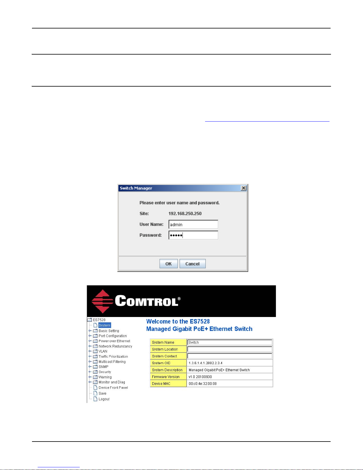
1. Open a command prompt window and ping the IP address for the RocketLinx ES7528 to verify a normal response time.
2. Launch the web browser (Internet Explorer or Mozilla Firefox) on the PC.
3. Type http://192.168.250.250 (or the IP address of the switch).and then press Enter.
4. Click Run if a security warning popup message appears.
5. Enter in user name, the password, and click OK. The default user name and password are both admin.
The Welcome page of the web management interface then appears.
16 - RocketLinx ES7528 Industrial Managed PoE Rack Mount User Guide: 2000509 Rev. A Using a Web Interface
Page 17
Preparation for Management
6. If you have not done so, you can change the RocketLinx ES7528 IP address to meet your network environment.
a. Double-click Basic Setting.
b. Click IP Configuration.
To use static addressing, enter a valid IP add dress, subnet mask and default gateway.
To use DHCP, click Enable in the DHCP Client drop list.
c. Click Apply.
To configure RocketLinx ES7528 features, go to Feature Configuration
on Page 23.
Secure Web Interface
The RocketLinx ES7528 web management page also provides secured management HTTPS login. All the configuration
commands are secure.
If you did not program the IP address for your network using NetVision (Programming Network Information Using NetVision
on Page 15), you need to change your computer IP address to 192.168.250.x (Network Mask: 255.255.0.0). The default IP
address for the RocketLinx ES7528 is 192.168.250.250.
1. Open a command prompt window and ping the IP address for the RocketLinx ES7528 to verify a normal response time.
2. Launch the web browser (Internet Explorer or Mozilla Firefox) on the PC.
3. Type http://192.168.250.250 (or the IP address of the switch).and then press Enter.
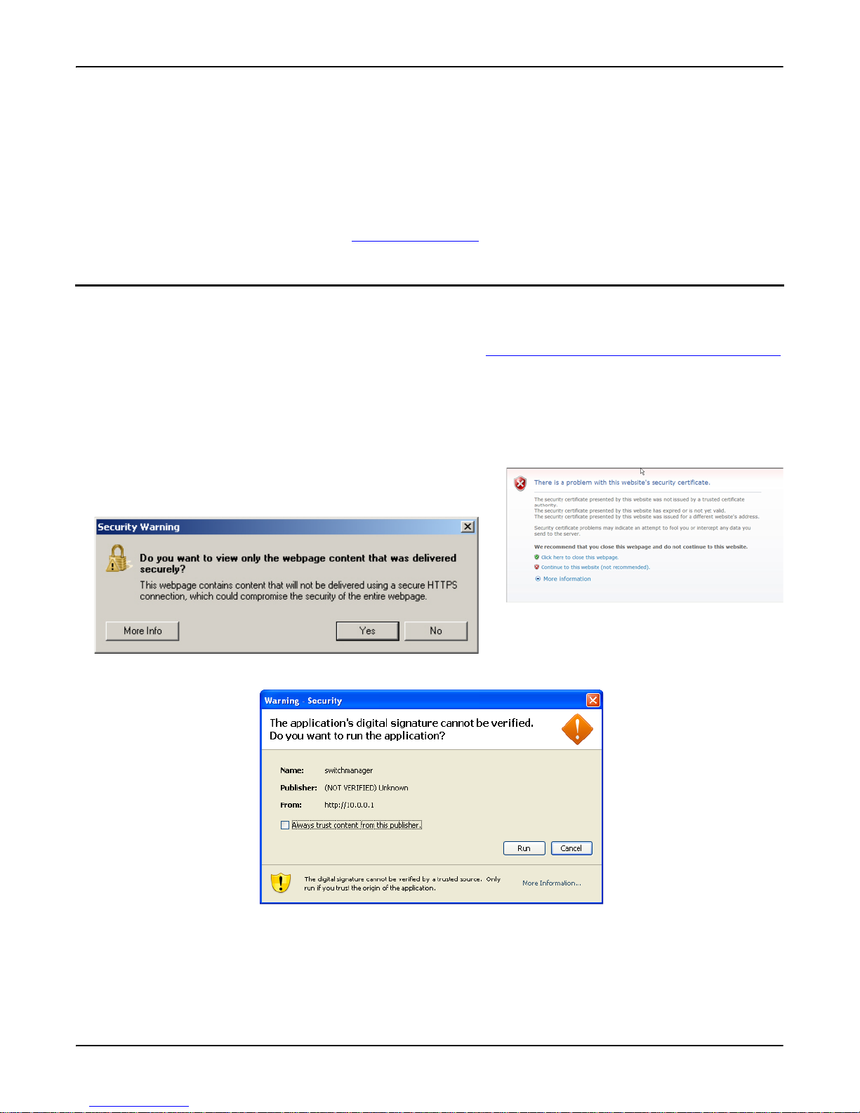
4. Click Continue to the web site (not recommended).
5. Click No when the popup screen appears and requests you to trust the
secured HTTPS connection distributed by the RocketLinx ES7528.
6. Click Run when requested to run the application (IP address).
Secure Web Interface RocketLinx ES7528 Industrial Managed PoE Rack Mount User Guide: 2000509 Rev. A - 17
Page 18
Preparation for Management
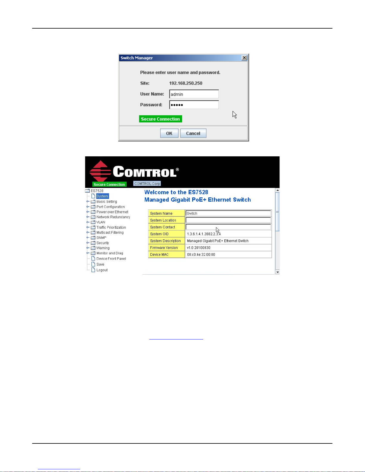
7. Enter the user name and the password. The default user name and password are admin and click OK.
The Welcome page of the web management interface then appears.
8. If you have not done so, you can change the RocketLinx ES7528 IP address to meet your network environment.
a. Double-click Basic Setting.
b. Click IP Configuration.
To use static addressing, enter a valid IP add dress, subnet mask and default gateway.
To use DHCP, click Enable in the DHCP Client drop list.
c. Click Apply.
To configure RocketLinx ES7528 features, go to Feature Configuration
18 - RocketLinx ES7528 Industrial Managed PoE Rack Mount User Guide: 2000509 Rev. A Secure Web Interface
on Page 23.
Page 19
Preparation for Management
Using the Command Line Interface (CLI)
Use the following procedures to access the RocketLinx ES7528 using the CLI:
• Using the Serial Console
• Using a Telnet Console
Using the Serial Console
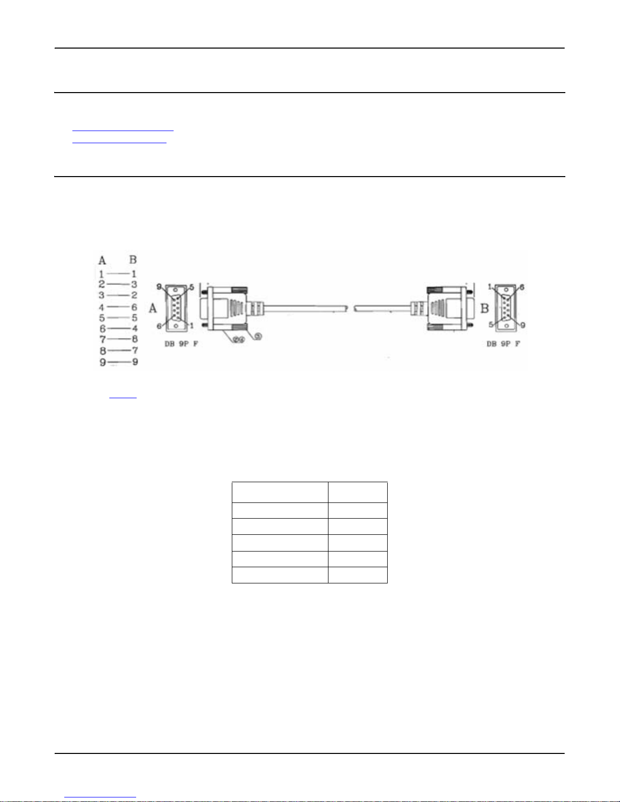
Comtrol provides one RS-232 DB9 console cable with the RocketLinx ES7528.
1. Attach one end of the RS-232 DB9 connector to your PC COM port and connect the other end to the Console port of the
RocketLinx ES7528. If you misplace the cable, you can use this console cable pin assignment or purchase a null-modem
cable.
2. Start a terminal program such as HyperTerminal or the Comtrol Test Terminal program. You can download Test Terminal
from the ftp site
• HyperTerminal
- Go to Start -> Program -> Accessories -> Communications -> HyperTerminal
- Enter a name for the new console connection and click OK.
- Select the appropriate COM port number.
- Set the serial settings.
-Press the Enter key in the Terminal window,
• Test Terminal (WCom2)
- Unzip Test Terminal and execute Wcom2.exe.
-Select Open Port and click the appropriate COM name.
- Click Settings, use the table (above), and then click Ok.
-Press the Enter key in the Terminal window,
After it is connected, you can see the Switch login request.
or locate it on the CD shipped with the RocketLinx ES7528.
Serial Settings Value
Baud Rate 9600
Data bits 8
Parity None
Stop Bit 1
Flow Control None
Using the Command Line Interface (CLI) RocketLinx ES7528 Industrial Managed PoE Rack Mount User Guide: 2000509 Rev. A - 19
Page 20

Preparation for Management
Switch login: admin
Password:
RocketLinx ES7528 (version 1.0-20100930-15:49:56).
Switch>
Switch> enable
Switch# configure terminal
Switch(config)# int vlan1
Switch(config-if)# ip address 192.168.11.252/16
3. Log in to the switch. The default user name is admin, password, admin.
4. If necessary, configure the IP address for your network. The following example shows how to program an IP address of
192.168.11.252 with a Class B subnet mask (255.255.0.0).
Refer to Page 44 for information about additional commands that are available for IP configuration.
To configure RocketLinx ES7528 features with the CLI, go to Feature Configuration
on Page 23.
20 - RocketLinx ES7528 Industrial Managed PoE Rack Mount User Guide: 2000509 Rev. A Using the Serial Console
Page 21
Preparation for Management
Using a Telnet Console
The RocketLinx ES7528 supports a Telnet console or SSH console with the command line interface, which is the same as what
you see using the RS-232 console port. The SSH connection can secure all the configuration commands you send to the
RocketLinx ES7528.
SSH is a client/server architecture while the RocketLinx ES7528 is the SSH server. When you want to make SSH connection
with the RocketLinx ES7528, you should download the SSH client tool first.
Use the appropriate discussion for your environment:
• Telnet
• SSH Client
Telnet
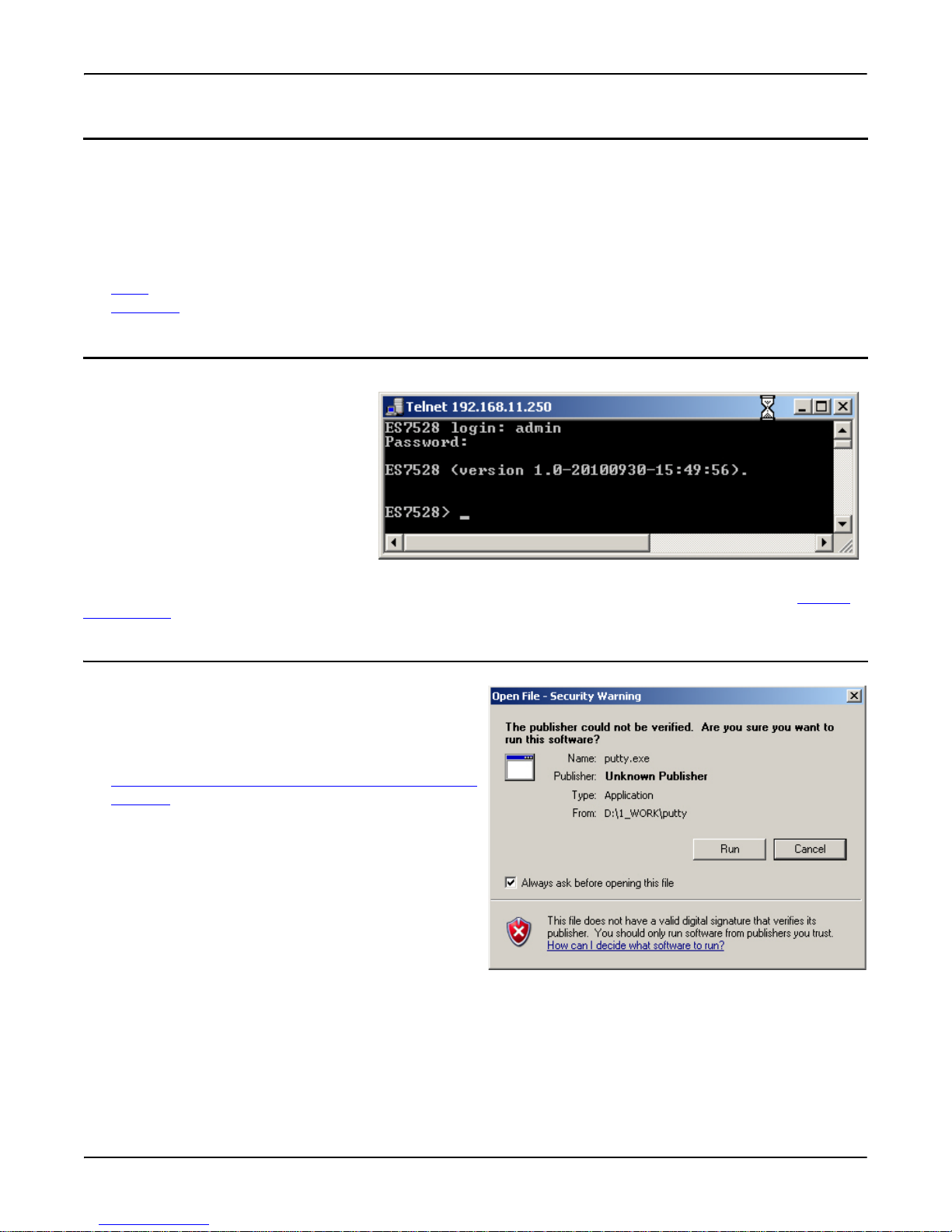
Below are the steps to open Telnet
connection to the switch.
1. Go to Start -> Run -> cmd and then
press Enter.
2. Type Telnet 192.168.250.250 (or the IP
address of the RocketLinx ES7528) and
then press Enter.
3. Enter the Login Name and Password.
The default login name and password
are admin.
All the commands you see in SSH are the
same as the CLI commands you see through the RS-232 console. To configure RocketLinx ES7528 features, go to Feature
Configuration on Page 23.
SSH Client
There are many free, sharewares, trials or charged SSH clients
you can find on the internet. For example, PuTTY is a free and
popular Telnet/SSH client. The following procedures shows
how to login with SSH and PuTTY.
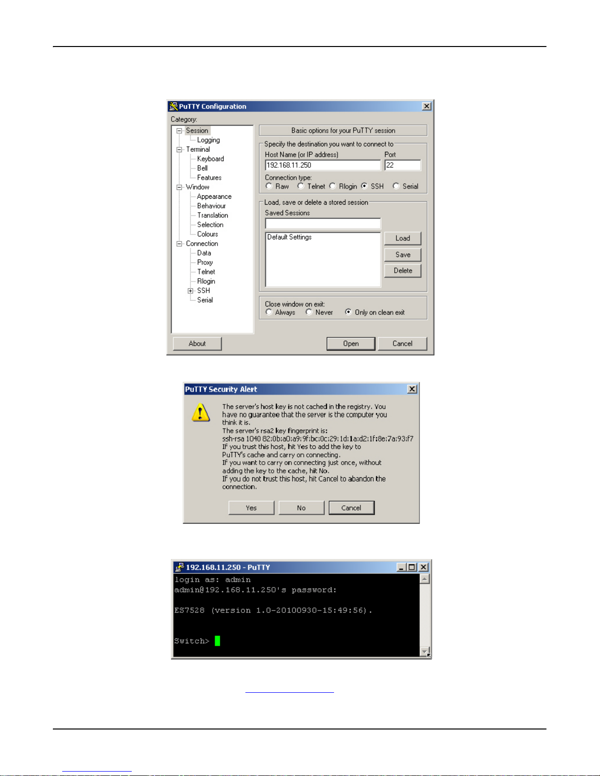
1. Download PuTTY (the Telnet and SSH client itself) from:
http://www.chiark.greenend.org.uk/~sgtatham/putty/download.html
2. Click Run to start PuTTY.
Using a Telnet Console RocketLinx ES7528 Industrial Managed PoE Rack Mount User Guide: 2000509 Rev. A - 21
Page 22
Preparation for Management
3. In the Session configuration, enter the Host Name (IP Address of the RocketLinx ES7528), Port number (default = 22),
click SSH for the protocol, and then click Open to start the SSH session console.
4. After click Open, you will see the cipher information in the popup screen. Click Yes to accept the Security Alert.
After few seconds, the SSH connection to the RocketLinx ES7528 opens.
5. Enter the Login Name and Password. The default login name and password are admin.
All the commands you see in SSH are the same as the CLI commands you see through the RS-232 console.
To configure RocketLinx ES7528 features, go to Feature Configuration
22 - RocketLinx ES7528 Industrial Managed PoE Rack Mount User Guide: 2000509 Rev. A SSH Client
on Page 23.
Page 23

Feature Configuration
This section explains how to configure the RocketLinx ES7528 software features. There are four ways to access the
RocketLinx ES7528. For information about accessing a configuration method, see the appropriate subsections.
• Serial console (Using the Serial Console
• Web browser (Using a Web Interface
• Telnet (Using a Telnet Console
This section discusses the configuring these software features:
• Command Line Interface Introduction
• Basic Setting on Page 29
• Port Configuration
• Power over Ethernet
• Network Redundancy
• VLAN
• Traffic Prioritization
• Multicast Filtering
• SNMP
• Security
• Warning
• Monitor and Diag
• Device Front Panel
• Save to Flash
• Logout
on Page 79
on Page 101
on Page 105
on Page 117
on Page 137
on Page 47
on Page 58
on Page 69
on Page 88
on Page 95
on Page 127
on Page 136
on Page 137
on Page 21)
on Page 19)
on Page 16)
Command Line Interface Introduction
The Command Line Interface (CLI) is the user interface to the RocketLinx ES7528 embedded software. You can view the
system information, show the status, configure the switch, and receive a response back from the system by keying in a
command.
There are several different command modes. Each command mode has its own access ability, available command lines and
uses different command lines to enter and exit. These modes are:
• User EXEC Mode
• Privileged EXEC Mode
• Global Configuration Mode
• (Port) Interface Configuration
• (VLAN) Interface Configuration
Refer to Preparation for Management
on Page 24
on Page 24
on Page 25
on Page 26
on Page 27
on Page 15 on Page to access the CLI.
Feature Configuration RocketLinx ES7528 Industrial Managed PoE Rack Mount User Guide: 2000509 Rev. A - 23
Page 24

Feature Configuration
Switch>
enable Turn on privileged mode command
exit Exit current mode and down to previous mode
list Print command list
ping Send echo messages
quit Exit current mode and down to previous mode
show Show running system information
telnet Open a telnet connection
traceroute Trace route to destination
Switch>enable
Switch#
archive manage archive files
clear Reset functions
clock Configure time-of-day clock
configure Configuration from vty interface
copy Copy from one file to another
debug Debugging functions (see also 'undebug')
disable Turn off privileged mode command
dot1x IEEE 802.1x standard access security control
end End current mode and change to enable mode
exit Exit current mode and down to previous mode
list Print command list
mac MAC interface commands
no Negate a command or set its defaults
pager Terminal pager
ping Send echo messages
quit Exit current mode and down to previous mode
reboot Reboot system
reload copy a default-config file to replace the current one
show Show running system information
telnet Open a telnet connection
terminal Set terminal line parameters
traceroute Trace route to destination
write Write running configuration to memory, network, or terminal
User EXEC Mode
When you login to the
RocketLinx ES7528 with the
CLI, you are in User EXEC
mode. You can ping, telnet
remote device, and show some
basic information.
Type enable to enter next mode,
exit to logout. ? to see the
command list.
Privileged EXEC Mode
Type enable in User EXEC mode, to enter the Privileged EXEC mode. In this mode, the system allows you to view current
configuration, reset default, reload switch, show system information, save configuration, and enter the global configuration
mode.
Type configure terminal to enter next mode, exit to leave. ? to see the command list.
24 - RocketLinx ES7528 Industrial Managed PoE Rack Mount User Guide: 2000509 Rev. A User EXEC Mode
Page 25

Global Configuration Mode
Switch# configure terminal
Switch(config)#
access-list Add an access list entry
administrator Administrator account setting
clock Configure time-of-day clock
default Set a command to its defaults
dot1x IEEE 802.1x standard access security control
end End current mode and change to enable mode
exit Exit current mode and down to previous mode
gmrp GMRP protocol
gvrp GARP VLAN Registration Protocol
hostname Set system's network name
interface Select an interface to configure
ip IP information
lacp Link Aggregation Control Protocol
list Print command list
lldp Link Layer Discovery Protocol
log Logging control
mac Global MAC configuration subcommands
mac-address-table mac address table
mirror Port mirroring
nameserver DNS Server
no Negate a command or set its defaults
ntp Configure NTP
poe Configure Power over Ethernet
ptpd IEEE1588 Precision Timne Protocol
qos Quality of Service (QoS)
redundant-ring Configure redundant ring
relay relay output type information
router Enable a routing process
sfp Small form-factor pluggable
smtp-server SMTP server configuration
snmp-server SNMP server
spanning-tree spanning tree algorithm
system System setting
trunk Trunk group configuration
vlan Virtual LAN
warning-event Warning event selection
write-config Specify config files to write to
Enter configure terminal in privileged EXEC mode. You can then enter global configuration mode. In global configuration
mode, you can configure all the features that the system provides you.
Type interface IFNAME/VLAN to enter interface configuration mode, exit to leave. ? to see the command list.
Available command lists of global configuration mode.
Global Configuration Mode RocketLinx ES7528 Industrial Managed PoE Rack Mount User Guide: 2000509 Rev. A - 25
Feature Configuration
Page 26

Feature Configuration
Switch(config)# interface fa1
Switch(config-if)#
acceptable Configure 802.1Q acceptable frame types of a port
auto-negotiation Enable auto-negotiation state of a given port
description Interface specific description
dot1x IEEE 802.1x standard access security control
duplex Specify duplex mode of operation for a port
end End current mode and change to enable mode
exit Exit current mode and down to previous mode
flowcontrol Set flow-control value for an interface
garp General Attribute Registration Protocol
ingress 802.1Q ingress filtering features
ip Interface Internet Protocol config commands
lacp Link Aggregation Control Protocol
list Print command list
loopback Specify loopback mode of operation for a port
mac MAC interface commands
mdix Enable mdix state of a given port
no Negate a command or set its defaults
poe Configure Power over Ethernet
qos Quality of Service (QoS)
quit Exit current mode and down to previous mode
rate-limit Rate limit configuration
sfp Small form-factor pluggable
shutdown Shutdown the selected interface
spanning-tree spanning-tree protocol
speed Specify the speed of a Fast Ethernet port
storm-control Enables packet flooding rate limiting features
switchport Set switching mode characteristics
(Port) Interface Configuration
Type interface IFNAME in global configuration mode. You can then enter Interface Configuration mode. In this mode, you
can configure port settings.
The port interface name for Fast Ethernet port 1 is fa1, Fast Ethernet 7 is fa7, gigabit Ethernet Port 25 is gi25 gigabit Ethernet
Port 28 is gi28. Type the interface name accordingly, when you want to enter certain interface configuration mode.
Type exit to leave.
Type ? to see the command list
Available command lists of the Port Interface Configuration mode.
26 - RocketLinx ES7528 Industrial Managed PoE Rack Mount User Guide: 2000509 Rev. A (Port) Interface Configuration
Page 27

(VLAN) Interface Configuration
Switch(config)# interface vlan 1
Switch(config-if)#
description Interface specific description
end End current mode and change to enable mode
exit Exit current mode and down to previous mode
ip Interface Internet Protocol config commands
list Print command list
no Negate a command or set its defaults
quit Exit current mode and down to previous mode
shutdown Shutdown the selected interface
Press interface VLAN VLANID in global configuration
mode. You can then enter
VLAN interface configuration
mode. In this mode, you can
configure the settings for the
specific VLAN.
The VLAN interface name of
VLAN 1 is VLAN 1, VLAN 2
is VLAN 2…
Type exit to leave the mode.
Type ? to see the available
command list.
The command lists of the
VLAN interface configuration
mode.
This table is a summary of the five command modes.
Command Mode Main Function Enter and Exit Method Prompt
User EXEC This is the first level of
access.
You can ping, telnet remote
device, and show some basic
information
Privileged EXEC In this mode, the system
allows you to view current
configuration, reset default,
reload switch, show system
information, save
configuration and enter
global configuration mode.
Global
configuration
In global configuration
mode, you can configure all
the features that the system
provides you.
Port Interface
configuration
In this mode, you can
configure port related
settings.
VLAN Interface
Configuration
In this mode, you can
configure settings for
specific VLAN.
(VLAN) Interface Configuration RocketLinx ES7528 Industrial Managed PoE Rack Mount User Guide: 2000509 Rev. A - 27
Enter: Login successfully
Exit: exit to logout.
Next mode: Type enable to enter privileged
EXEC mode.
Enter: Type enable in User EXEC mode.
Exec: Type disable to exit to User EXEC
mode.
Type exit to logout
Next Mode: Type configure terminal to
enter global configuration command.
Enter: Type configure terminal in
privileged EXEC mode
Exit: Type exit or end or press Ctrl-Z to
exit.
Next mode: Type interface IFNAME/
VLAN VID to enter interface configuration
mode
Enter: Type interface IFNAME in global
configuration mode.
Exit: Type exit or Ctrl+Z
nfiguration mode. Type end to privileged
co
EXEC mode.
Enter: Type interface VLAN VID in
global configuration mode.
Exit: Type exit or Ctrl+Z to global
configuration mode. Type end to privileged
EXEC mode.
Feature Configuration
Switch>
Switch#
Switch(config)#
Switch(config-if)#
to global
Switch(config-vlan)#
Page 28
Feature Configuration
Switch(config)# interface (?)
IFNAME Interface's name
vlan Select a vlan to configure
Switch(config)# a?
access-list Add an access list entry
administrator Administrator account setting
arp Set a static ARP entry
Switch# co (tab) (tab)
Switch# configure terminal
Switch(config)# ac (tab)
Switch(config)# access-list
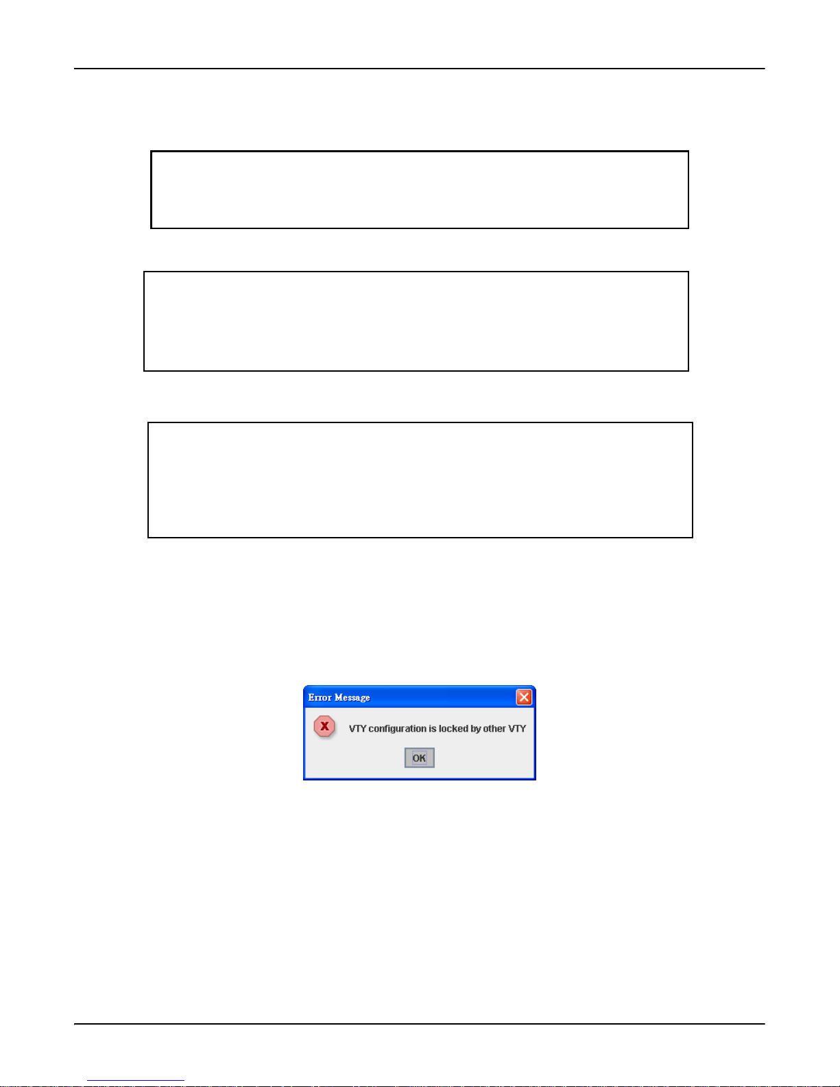
The following are useful commands to save you typing time in typing and to avoid typing errors.
? To see all of the available commands in this mode. It helps you to see the next command you can/should type as well.
(Character)? To see all of the available commands starting with this character.
Tab The tab key helps you to input the command quicker. If there is only one available command in the next, click the tab key
to help finish the typing.
Ctrl+C To stop executing the unfinished command.
Ctrl+S To lock the screen of the terminal. You can’t input any command.
Ctrl+Q To unlock the screen which is locked by Ctrl+S.
Ctrl+Z To exit configuration mode.
An alert message appears when multiple users are attempting to configure the switch. If the administrator is in Configuration
mode, then the web users cannot change settings. The RocketLinx ES7528 allows only one administrator to configure the
switch at a time.
28 - RocketLinx ES7528 Industrial Managed PoE Rack Mount User Guide: 2000509 Rev. A (VLAN) Interface Configuration
Page 29
Basic Setting
Basic Setting
The Basic Setting group provides you to configure switch information, IP address, User name/Password of the system. It also
allows you to do firmware upgrade, backup and restore configuration, reload factory default, and reboot the system. The
following commands are included in this group:
• Switch Setting
• Admin Password
• IP Configuration
• Time Setting
• Jumbo Frame
• DHCP Server Configuration
• Backup and Restore
• Firmware Upgrade
• Factory Defaults
• System Reboot
• CLI Commands for Basic Setting
Switch Setting
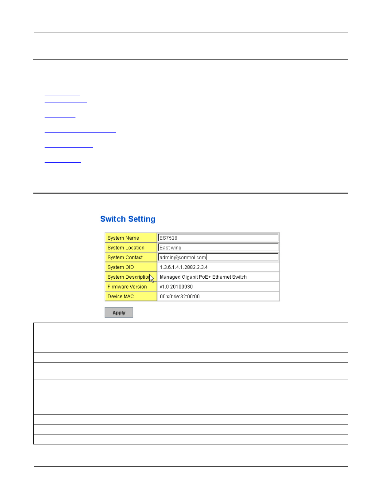
You can assign System name, Location, Contact and view system information.
on Page 29
on Page 30
on Page 30
on Page 31
on Page 34
on Page 35
on Page 38
on Page 39
on Page 40
on Page 41
on Page 42
Switch Setting Description
System Name You can assign a name to the device. You can input up to 64 characters. After you configure the
name, The CLI system selects the first 12 characters as the name in CLI system.
System Location You can specify the switch’s physical location with up to 64 characters.
System Contact You can specify contact people with up to 64 characters by typing the name, mail address or other
information of the administrator.
System OID The SNMP object ID of the switch. You can follow the path to find its private MIB in MIB
browser.
Note: When you attempt to view private MIB, you should first compile private MIB files into
your MIB browser.
System Description Managed Gigabit PoE + Ethernet Switch is the system description of this product.
Firmware Version Displays the firmware version installed in this device.
Device MAC Displays a unique hardware address (MAC address) assigned in the factory.
Basic Setting RocketLinx ES7528 Industrial Managed PoE Rack Mount User Guide: 2000509 Rev. A - 29
Page 30
Admin Password
Switch Setting Description
Apply Click Apply to apply the settings.
Note: You must Save the settings (Page 137), if you want to maintain these settings if the
RocketLinx ES7528 is powered off.
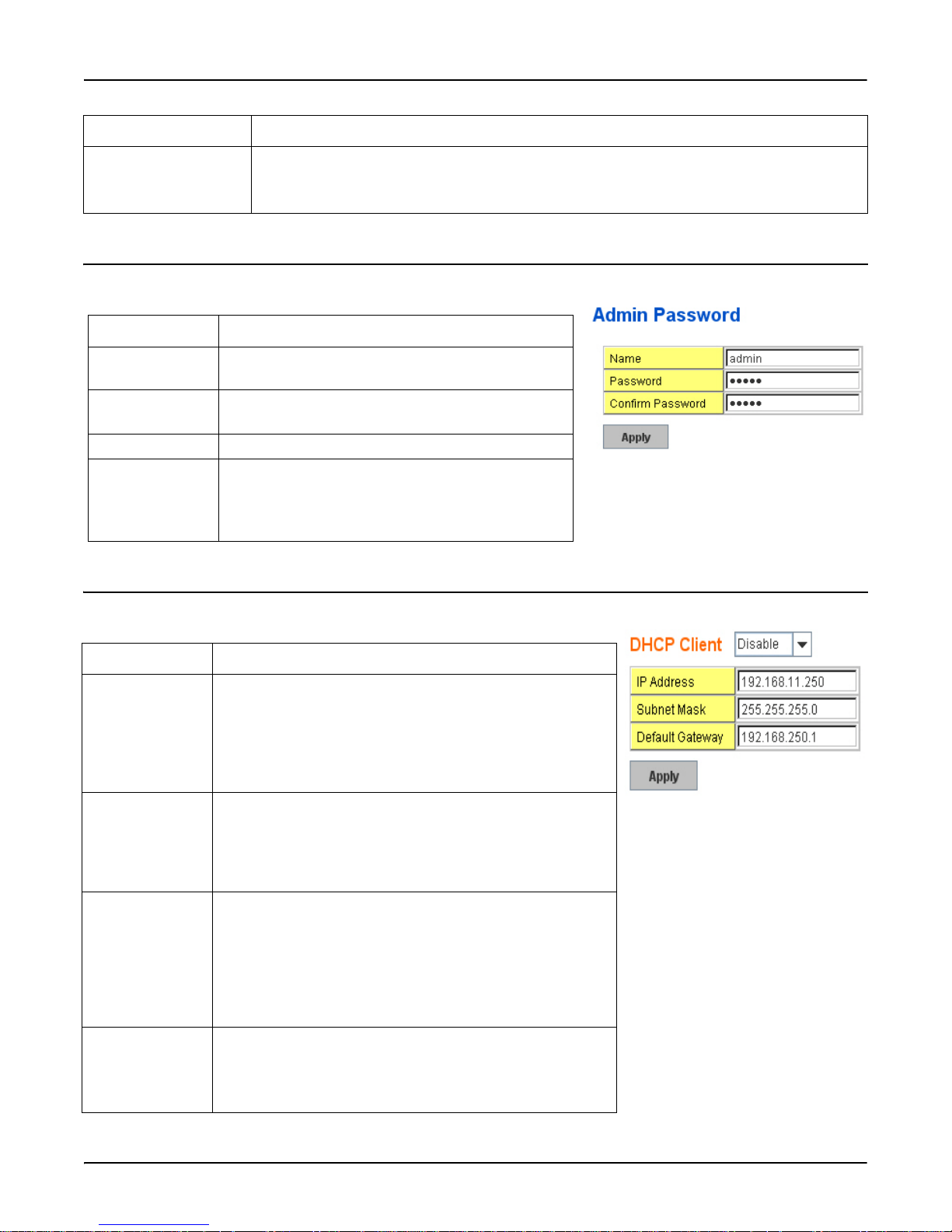
Admin Password
You can change the user name and the password here to enhance security.
Admin Password Description
User name You can enter a new user name here. The default setting
is admin.
Password You can enter a new password here. The default setting
is admin.
Confirm Password You need to type the new password again to confirm it.
Apply Click Apply to apply the settings.
Note: You must Save the settings (Page 137), if you
want to maintain these settings if the
RocketLinx ES7528 is powered off.
IP Configuration
This function allows you to configure the switch’s IP address settings.
IP Configuration Description
DHCP Client You can select to Enable or Disable the DHCP Client function.
When the DHCP Client function is enabled, an IP address is
assigned to the switch from the network’s DHCP server. In this
mode, the default IP address is replaced by the one assigned by
DHCP server. If DHCP Client is disabled, then the IP address
that you specified is used.
IP Address You can assign the IP address reserved by your network for the
RocketLinx ES7528. If the DHCP Client function is enabled,
you do not need to assign an IP address to the RocketLinx
ES7528, because it is overwritten by the DHCP server and displays here. The default IP is 192.168.250.250.
Subnet Mask You can assign the subnet mask for the IP address here. If the
DHCP Client function is enabled, you do not need to assign the
subnet mask. The default Subnet Mask is 255.255.255.0.
Note: In the CLI, the enabled bit of the subnet mask is used to
represent the number displayed in the web management
interface. For example, 8 represents: 255.0.0.0,16
represents: 255.255.0.0, 24 represents: 255.255.255.0.
Default Gateway You can assign the gateway for the switch here. The default
gateway is 192.168.250.1.
Note: In the CLI, use 0.0.0.0/0 to represent the default
gateway.
30 - RocketLinx ES7528 Industrial Managed PoE Rack Mount User Guide: 2000509 Rev. A Admin Password
Page 31
Time Setting
IP Configuration Description
DNS Server The Domain Name System (DNS) is a hierarchical naming
system built on a distributed database for computers, services,
or any resource connected to the Internet or a private network.
It associates various information with domain names assigned
to each of the participating entities. Most importantly, it
translates domain names meaningful into the numerical
identifiers associated with networking equipment for the
purpose of locating and addressing these devices worldwide.
Apply Click Apply to apply the settings.
Note: You must Save the settings (Page 137), if you want to
maintain these settings if the RocketLinx ES7528 is
powered off.
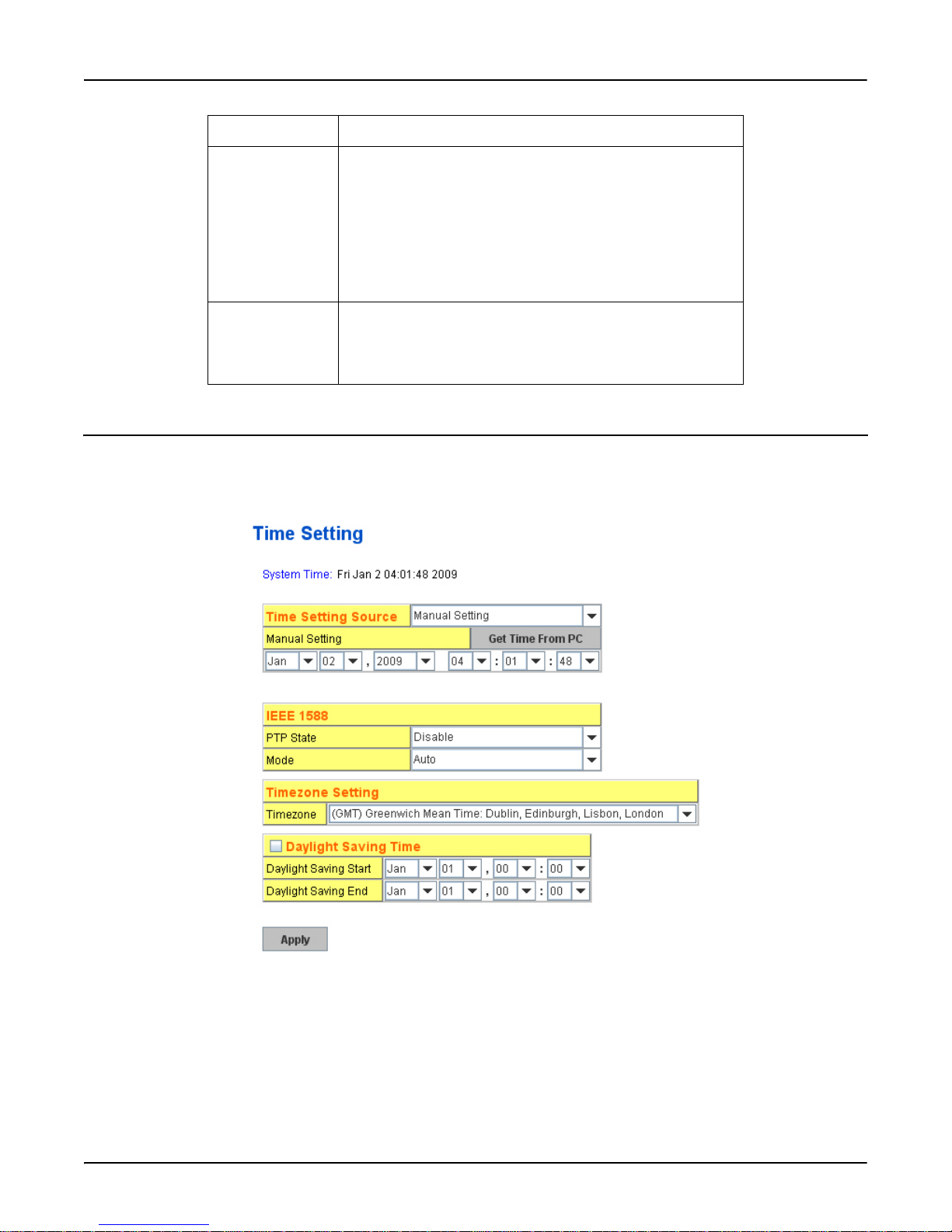
Time Setting
Time Setting allows you to set the time manually or through an NTP server. Network Time Protocol (NTP) is used to
synchronize computer clocks on the internet. You can configure NTP settings here to synchronize the clocks of several
switches on the network.
Time Setting RocketLinx ES7528 Industrial Managed PoE Rack Mount User Guide: 2000509 Rev. A - 31
Page 32

Time Setting
The RocketLinx ES7528 also provides Daylight Saving function.
Time Setting Description
Time Setting Source Manual Setting: Click Manual setting to change time as needed. You can also click the Get Time
from PC button to get PC’s time setting for switch.
NTP client: Select the Time Setting Source so that the NTP client permits the RocketLinx ES7528
to enable the NTP client service. NTP client is automatically enabled if you change Time source to
NTP Client. The system sends a request packet to acquire current time from the NTP server you
assigned.
IEEE 1588 With the Precision Time Protocol IEEE 1588 there is a standard available that makes it possible to
synchronize the clocks of different end devices over a network at speeds faster than one microsecond.
To enable IEEE 1588, select Enable in the PTP Status and choose Auto, Master or Slave Mode.
After the time is synchronized, the system time displays the correct time from the PTP server.
Timezone Setting Select the time zone where the switch is located. The following table lists the time zones for different
locations for your reference. The default time zone is GMT Greenwich Mean Time.
Daylight Saving Time Set to when the Enable Daylight Saving Time start and end, during the Daylight Saving Time, the
device’s time is one hour earlier than the actual time.
Apply Click Apply to apply the settings.
Note: You must Save the settings (Page 137), if you want to maintain these settings if the
RocketLinx ES7528 is powered off.
Switch(config)# clock timezone
01 (GMT-12:00) Eniwetok, Kwajalein
02 (GMT-11:00) Midway Island, Samoa
03 (GMT-10:00) Hawaii
04 (GMT-09:00) Alaska
05 (GMT-08:00) Pacific Time (US & Canada), Tijuana
06 (GMT-07:00) Arizona
07 (GMT-07:00) Mountain Time (US & Canada)
08 (GMT-06:00) Central America
09 (GMT-06:00) Central Time (US & Canada)
10 (GMT-06:00) Mexico City
11 (GMT-06:00) Saskatchewan
12 (GMT-05:00) Bogota, Lima, Quito
13 (GMT-05:00) Eastern Time (US & Canada)
14 (GMT-05:00) Indiana (East)
15 (GMT-04:00) Atlantic Time (Canada)
16 (GMT-04:00) Caracas, La Paz
17 (GMT-04:00) Santiago
18 (GMT-03:00) NewFoundland
19 (GMT-03:00) Brasilia
20 (GMT-03:00) Buenos Aires, Georgetown
21 (GMT-03:00) Greenland
22 (GMT-02:00) Mid-Atlantic
23 (GMT-01:00) Azores
24 (GMT-01:00) Cape Verde Is.
25 (GMT) Casablanca, Monrovia
26 (GMT) Greenwich Mean Time: Dublin, Edinburgh, Lisbon, London
27 (GMT+01:00) Amsterdam, Berlin, Bern, Rome, Stockholm, Vienna
32 - RocketLinx ES7528 Industrial Managed PoE Rack Mount User Guide: 2000509 Rev. A Time Setting
Page 33

28 (GMT+01:00) Belgrade, Bratislava, Budapest, Ljubljana, Prague
29 (GMT+01:00) Brussels, Copenhagen, Madrid, Paris
30 (GMT+01:00) Sarajevo, Skopje, Sofija, Vilnius, Warsaw, Zagreb
31 (GMT+01:00) West Central Africa
32 (GMT+02:00) Athens, Istanbul, Minsk
33 (GMT+02:00) Bucharest
34 (GMT+02:00) Cairo
35 (GMT+02:00) Harare, Pretoria
36 (GMT+02:00) Helsinki, Riga, Tallinn
37 (GMT+02:00) Jerusalem
38 (GMT+03:00) Baghdad
39 (GMT+03:00) Kuwait, Riyadh
40 (GMT+03:00) Moscow, St. Petersburg, Volgograd
41 (GMT+03:00) Nairobi
42 (GMT+03:30) Tehran
43 (GMT+04:00) Abu Dhabi, Muscat
44 (GMT+04:00) Baku, Tbilisi, Yerevan
45 (GMT+04:30) Kabul
46 (GMT+05:00) Ekaterinburg
47 (GMT+05:00) Islamabad, Karachi, Tashkent
48 (GMT+05:30) Calcutta, Chennai, Mumbai, New Delhi
49 (GMT+05:45) Kathmandu
50 (GMT+06:00) Almaty, Novosibirsk
51 (GMT+06:00) Astana, Dhaka
52 (GMT+06:00) Sri Jayawardenepura
53 (GMT+06:30) Rangoon
54 (GMT+07:00) Bangkok, Hanoi, Jakarta
55 (GMT+07:00) Krasnoyarsk
56 (GMT+08:00) Beijing, Chongqing, Hong Kong, Urumqi
57 (GMT+08:00) Irkutsk, Ulaan Bataar
58 (GMT+08:00) Kuala Lumpur, Singapore
59 (GMT+08:00) Perth
60 (GMT+08:00) Taipei
61 (GMT+09:00) Osaka, Sapporo, Tokyo
62 (GMT+09:00) Seoul
63 (GMT+09:00) Yakutsk
64 (GMT+09:30) Adelaide
65 (GMT+09:30) Darwin
66 (GMT+10:00) Brisbane
67 (GMT+10:00) Canberra, Melbourne, Sydney
68 (GMT+10:00) Guam, Port Moresby
69 (GMT+10:00) Hobart
70 (GMT+10:00) Vladivostok
71 (GMT+11:00) Magadan, Solomon Is., New Caledonia
72 (GMT+12:00) Aukland, Wellington
73 (GMT+12:00) Fiji, Kamchatka, Marshall Is.
74 (GMT+13:00) Nuku'alofa
Time Setting
Time Setting RocketLinx ES7528 Industrial Managed PoE Rack Mount User Guide: 2000509 Rev. A - 33
Page 34
Jumbo Frame
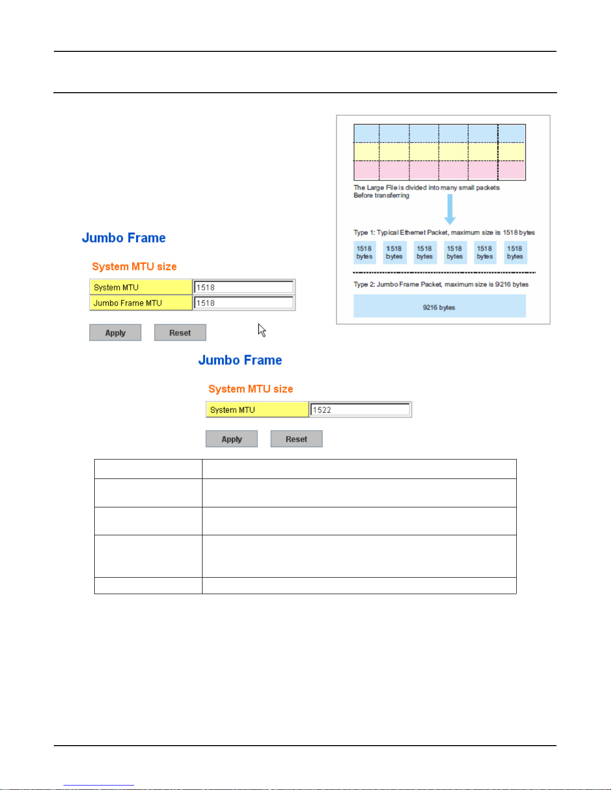
Jumbo Frame
The typical Ethernet frame range is from 64 to 1,518 bytes. This is
sufficient for general usages. However, when users want to transmit
large files, the files may be divided into many small size packets.
When the transmission speed becomes slow, long size Jumbo frame
may solve the issue.
The RocketLinx ES7528 allows you configure the size of the
Maximum Transmission Unit (MTU). The default value is 1,518
bytes. You can increase the MTU size to support jumbo frames on
all interfaces by setting the Jumbo Frame MTU. The maximum
Jumbo Frame size is 9,216 bytes. You can freely change the
available packet size.
Jumbo Frame Description
System MTU Change the MTU size for all Fast Ethernet interfaces on the switch stack. The
range is 1500 to 1546 bytes; the default is 1518 bytes.
Jumbo Frame MTU Change the MTU size for all gigabit Ethernet interfaces on the switch stack.
The range is 1500 to 9216 bytes; the default is 1518 bytes.
Apply Click Apply to apply the settings.
Note: You must Save the settings (Page 137), if you want to maintain these
settings if the RocketLinx ES7528 is powered off.
Reset Click to reset the MTU to the default value.
34 - RocketLinx ES7528 Industrial Managed PoE Rack Mount User Guide: 2000509 Rev. A Jumbo Frame
Page 35
DHCP Server Configuration
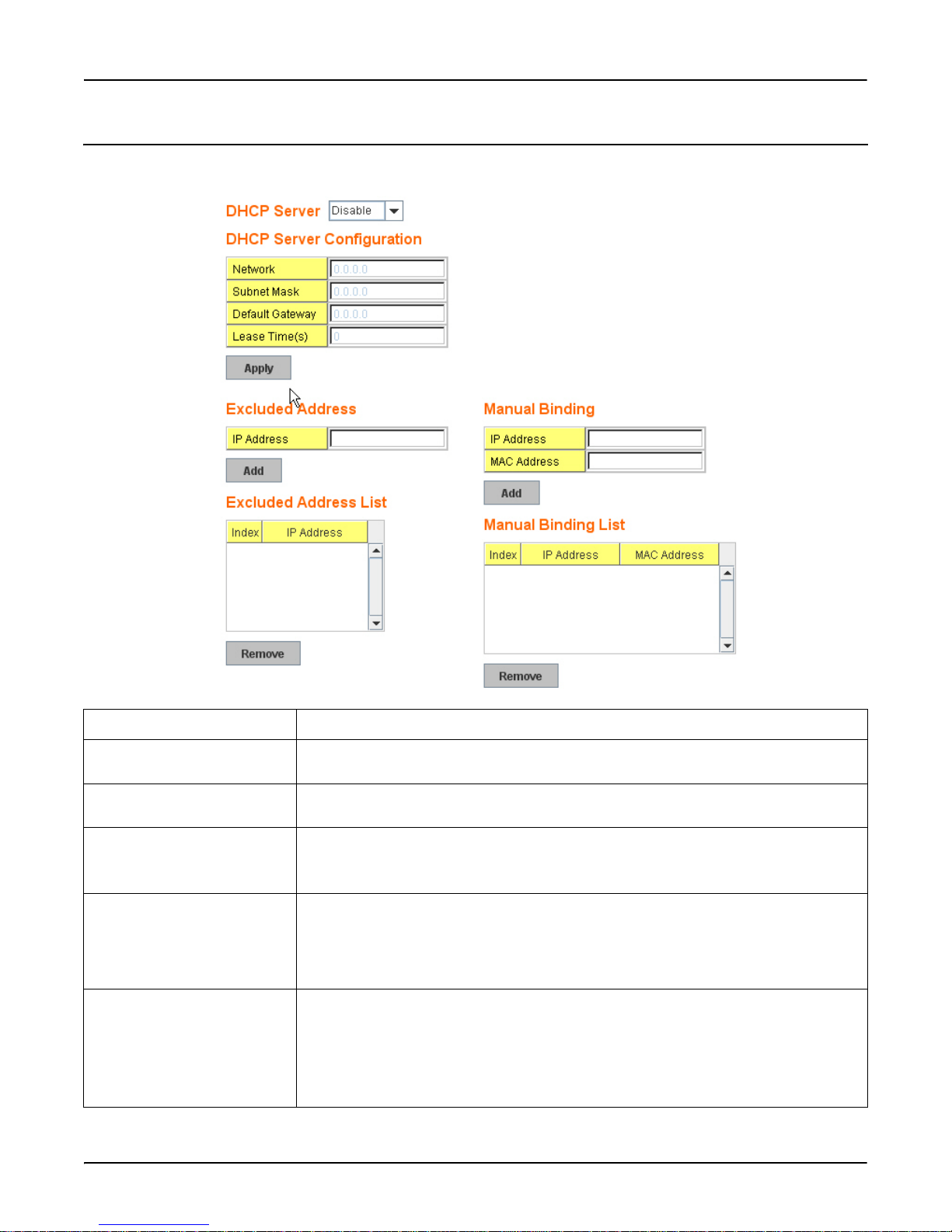
Use this page to configure DHCP server services.
DHCP Server Configuration
DHCP Server Configuration Description
DHCP Server You can select to Enable or Disable the DHCP Server function. The RocketLinx ES7528
assigns a new IP address to link partners.
DHCP Server Configuration After selecting to enable the DHCP Server function, type in the Network IP address for the
DHCP server IP pool, Subnet Mask, Default Gateway address, and Lease Time for client.
Apply Click Apply to apply the settings.
Note: You must Save the settings (Page 137), if you want to maintain these settings if the
RocketLinx ES7528 is powered off.
Excluded Address You can type a specific address into the IP Address field for the DHCP server reserved IP
address.
The IP address that is listed in the Excluded Address List Table is not assigned to the
network device. Add or remove an IP address from the Excluded Address List by
clicking Add or Remove.
Manual Binding The RocketLinx ES7528 provides a MAC address and IP address binding and removing
function. You can type in the specified IP and MAC address, and then click Add to add a
new MAC and IP address binding rule for a specified link partner, like a PLC, or any
device without DHCP client function.
The MAC address format is xxxx.xxxx.xxxx; for example, 00C0.4E33.0001.
To remove from the binding list, just select the rule to remove and click Remove.
DHCP Server Configuration RocketLinx ES7528 Industrial Managed PoE Rack Mount User Guide: 2000509 Rev. A - 35
Page 36
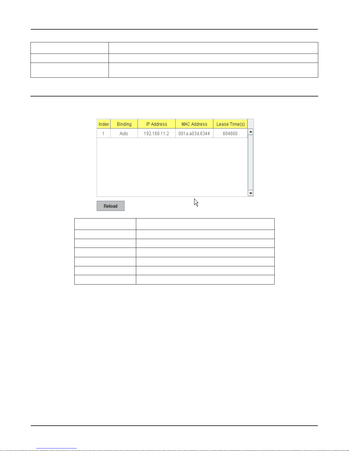
DHCP Leased Entries
DHCP Server Configuration Description
Add Click the appropriate Add button to add an excluded IP address or a manual binding entry.
Remove Click the Remove button to remove selected excluded IP addresses or a manual binding
entry.
DHCP Leased Entries
The RocketLinx ES7528 provides an assigned IP address.
DHCP Leased Entries Description
Index Index of DHCP leased entries.
Binding Manual or auto binding IP addresses and MAC addresses.
IP Address The IP address of the leased entry.
MAC Address The MAC Address of the leased entry.
Lease Time(s) The lease time of the leased entry (in seconds).
Reload Click to reload DHCP leased entries.
36 - RocketLinx ES7528 Industrial Managed PoE Rack Mount User Guide: 2000509 Rev. A DHCP Leased Entries
Page 37
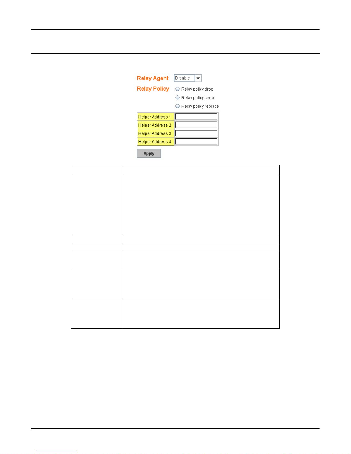
DHCP Relay Agent
This subsection discusses the DHCP Relay Agent.
DHCP Relay Agent Description
Relay Agent You can select to Enable or Disable DHCP relay agent function,
and then select the modification type of option 82 field.
The DHCP Information option referred to as Option 82 is normally
used in environments of large enterprise or metro networks to
provide additional data on the physical attachment of the client.
Option 82 is suggested for use in distributed DHCP server/relay
environments, where relays insert additional information to
identify the client’s attachment point.
Relay policy drop Drops the option 82 field and does not add any option 82 fields.
Relay policy keep Keeps the original option 82 field and forwards it to the server.
Relay policy replace Replaces the existing option 82 field and adds the new option 82
field. (This is the default setting)
Helper Address There are four fields for the DHCP server’s IP address. You can fill
the field with a preferred IP address of the DHCP Server. All the
DHCP packets from client are modified by the policy and forwarded to the DHCP server through the gateway port.
Apply Click Apply to apply the settings.
Note: You must Save the settings (Page 137), if you want to
DHCP Relay Agent
maintain these settings if the RocketLinx ES7528 is
powered off.
DHCP Relay Agent RocketLinx ES7528 Industrial Managed PoE Rack Mount User Guide: 2000509 Rev. A - 37
Page 38
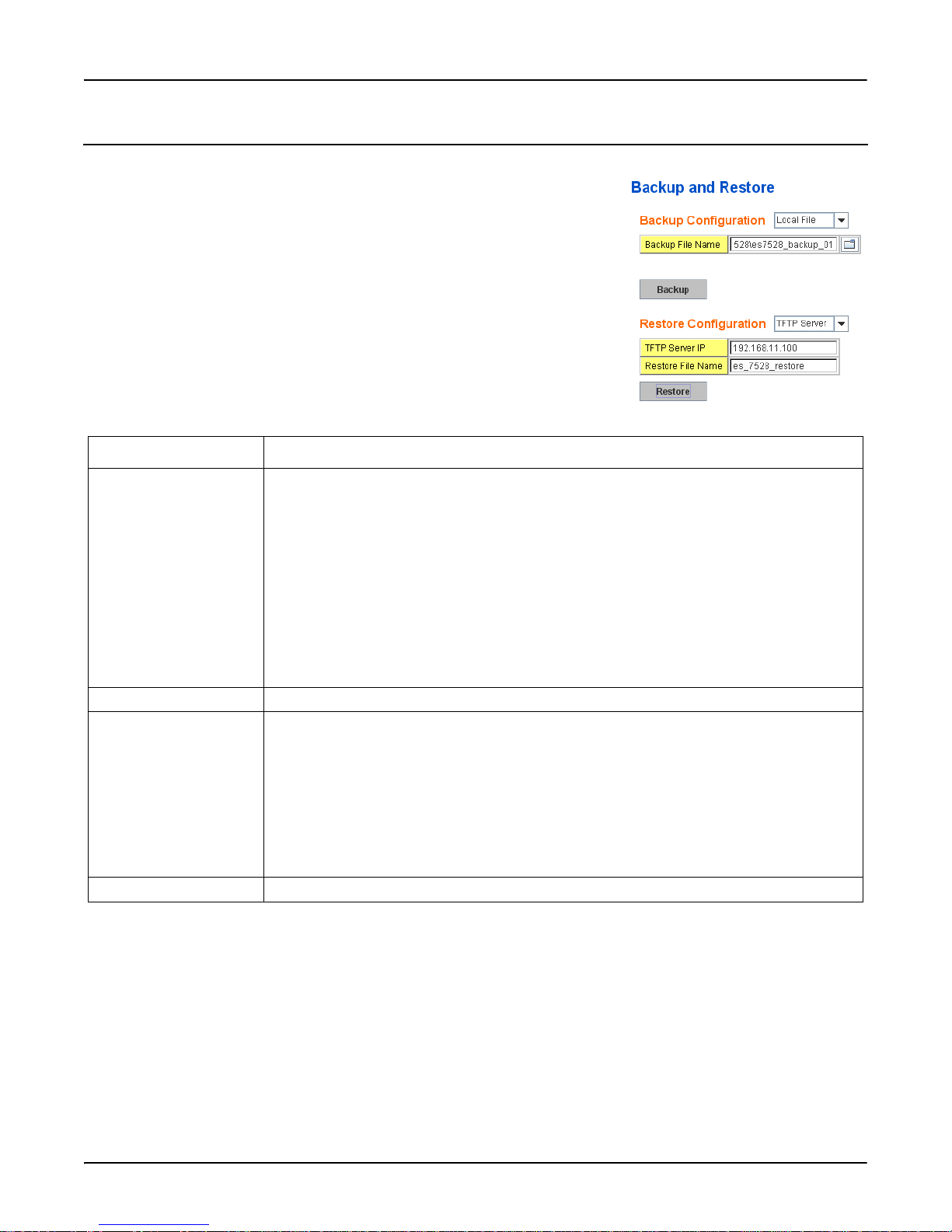
Backup and Restore
Backup and Restore
Use the Backup command to save the current configuration file saved in the switch’s
flash to admin PC or TFTP server. This allows you to go to the Restore command
later to restore the configuration file back to the RocketLinx ES7528. Before you
restore the configuration file, you must place the backup configuration file in the PC
or TFTP server. The switch then downloads this file back to the flash.
The RocketLinx ES7528configuration file is a pure text file. You can open the file
with Word or Notepad. You can also modify the file, add/remove the configuration
settings, and then restore back to the RocketLinx ES7528.
There are two modes to backup/restore the configuration file: Local File mode and
TFTP Server mode. Click the Folder icon to select the target file you want to backup/
restore.
Note: Folders of the path to the target file do not allow you to input space key.
Backup and Restore Description
Backup Configuration • Local File: In this mode, the switch acts as the file server. Browse to the target folder and
then type the file name to backup the configuration. You can also browse to the target
folder and select an existing configuration file to restore the configuration back to the
switch. This mode is only provided by the web UI as the backup and restore functions are
not supported by the CLI.
• TFTP Server: In this mode, the switch acts as TFTP client. Confirm that your TFTP
server is ready, then enter the IP address of TFTP Server and Backup configuration file
name. This mode can be used in both the CLI and web interface.
- TFTP Server IP Address: Enter the IP address of your TFTP Server.
- Backup File Name: Enter the name of the backup file.
Note: Pointing to the wrong file causes the entire configuration to be skipped.
Backup The Backup command can only backup the configuration file to your PC or TFTP server.
Restore Configuration You can select local file or TFTP server to restore startup configuration.
• Local File: The file name of startup configuration file to be uploaded.
Restore File Name: You can enter the configuration file name, or use file chooser to select
the configuration file to be uploaded to the switch.
• TFTP Server: Restore startup configurations via uploadable TFTP Server file.
- TFTP Server IP: The IP address of the TFTP server where your startup configuration
can be uploaded.
- Restore File Name: The file name of startup configuration file to be uploaded.
Restore Click to restore switch startup configurations to switch.
38 - RocketLinx ES7528 Industrial Managed PoE Rack Mount User Guide: 2000509 Rev. A Backup and Restore
Page 39
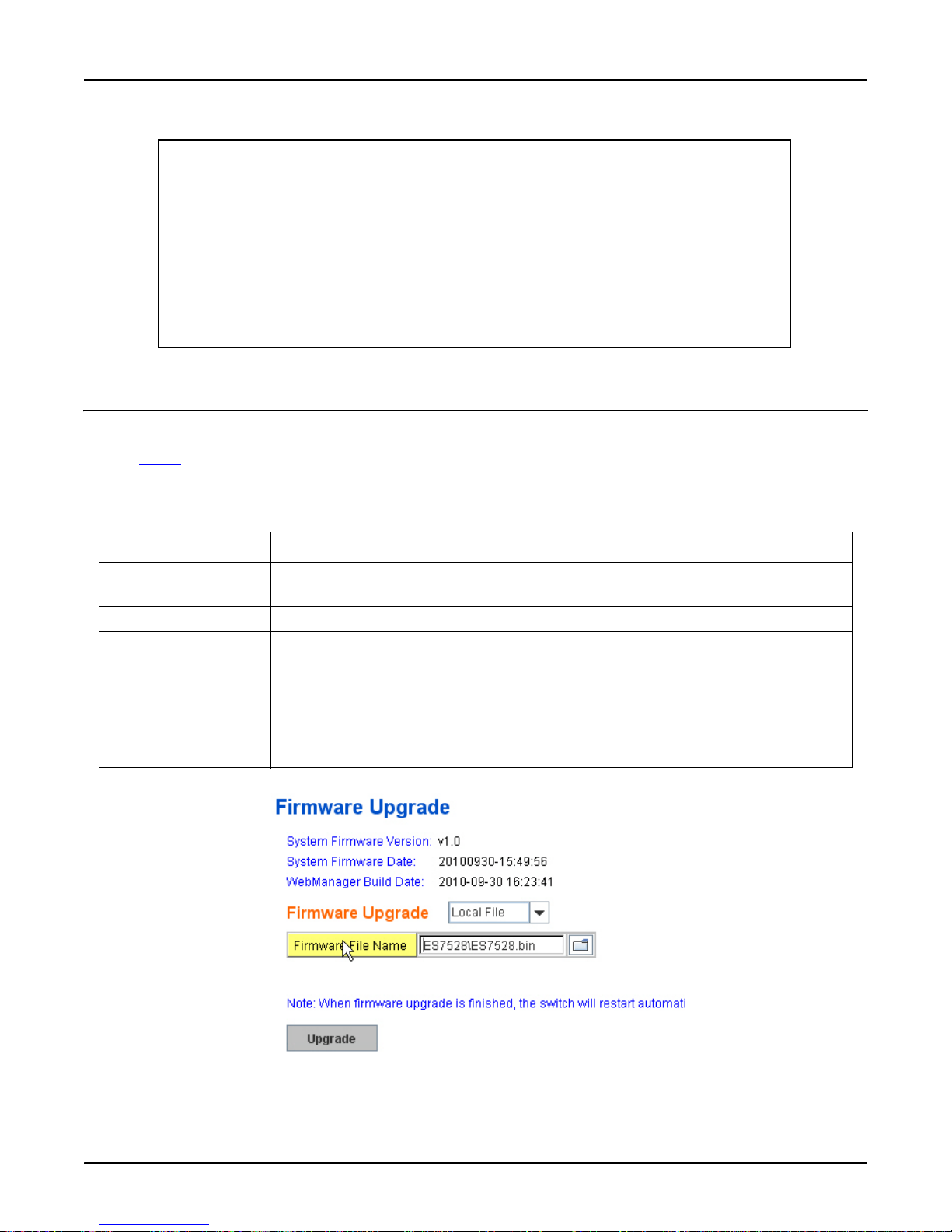
Firmware Upgrade
Technical Tip:
Default Configuration File: The switch provides the default configuration file in the system. You
can use the Reset button on the Factory Default page or the Reload command in the CLI to reset
the system.
Running Configuration File: The CLI allows you to view the latest settings running in the
ES7528. The information shown here are the settings you have set up, but have not yet saved to the
flash. The settings must be saved to the flash in order to work after a power recycle. You can use
show running-config to view it in CLI.
Startup Configuration File: After you saved the running-config to flash, the new settings are
kept an d work after the power is cycled. Use the show startup-config to view it in the CLI. The
Backup command can only backup the configuration file to your PC or TFTP server.
Firmware Upgrade
Use this section to update the RocketLinx ES7528 with the latest firmware. Comtrol provides the latest firmware on the
Comtrol ftp site
Support suggests you use the latest firmware before installing the switch at a customer site.
Note: The system will be automatically rebooted after you finish upgrading firmware. You should alert the attached users
before updating the firmware that network interruption may occur.
. The new firmware may include new features, bug fixes, or other software changes. Comtrol Technical
Firmware Upgrade Description
System Firmware Version The firmware version on the RocketLinx ES7528.
You should check the version number after the switch is rebooted.
System Firmware Date The build date of the firmware on the switch.
Firmware Upgrade Local File
• Upgrade the firmware using a local file.
• Browse to locate the Firmware File Name of the new firmware and click Upgrade.
TFTP Server:
• Upgrade the firmware by uploading the firmware using a TFTP server file.
• TFTP Server IP is the address of the TFTP server where the firmware files is located.
• Firmware File Name, type the file name of the firmware and then click Upgrade.
The following represents a firmware upgrade using local file mode.
Firmware Upgrade RocketLinx ES7528 Industrial Managed PoE Rack Mount User Guide: 2000509 Rev. A - 39
Page 40
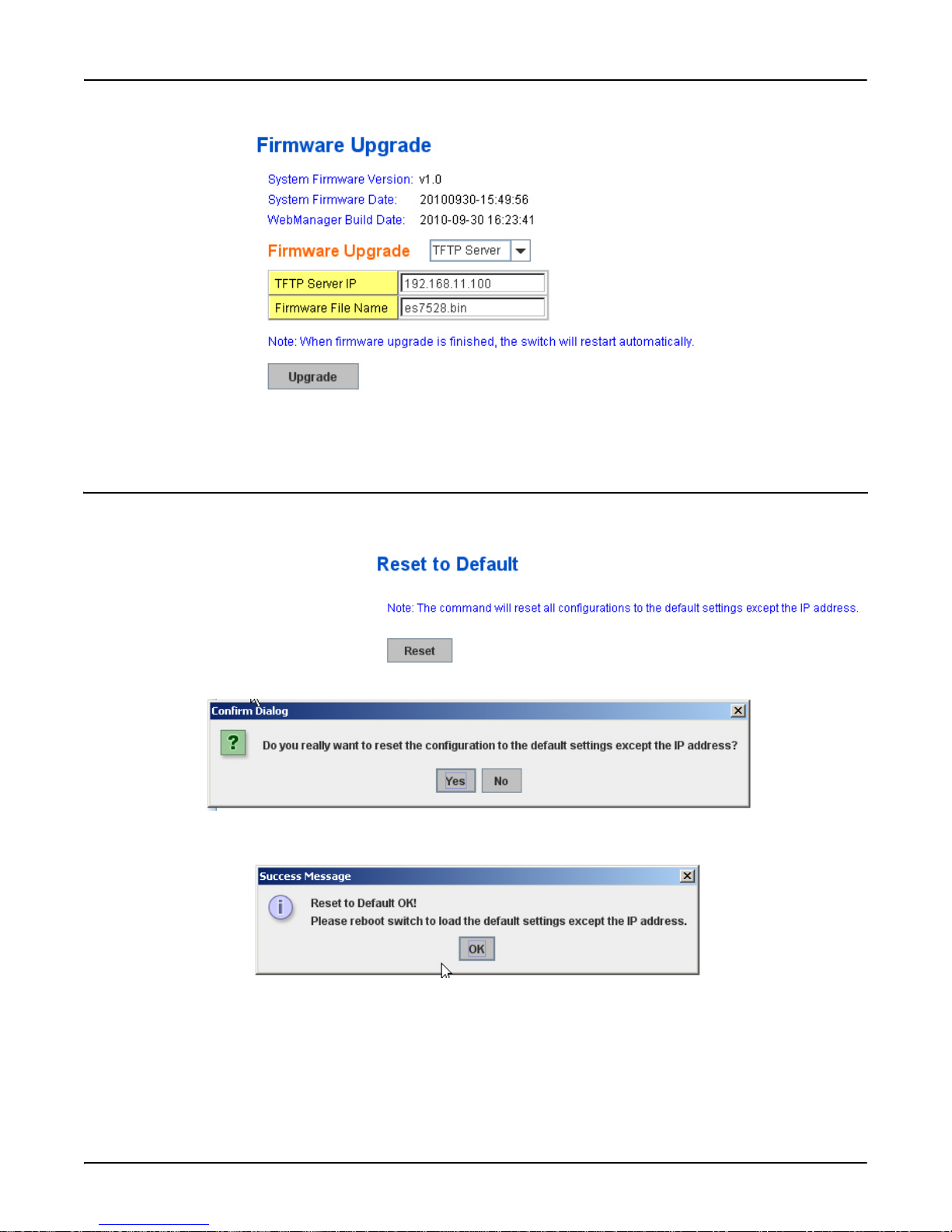
Factory Defaults
This represents a firmware upgrade in TFTP server mode.
After finishing transmitting the firmware, the system copies the firmware file and replace the firmware in the flash. The CLI
show …… until the process is finished.
Factory Defaults
You can reset all the configurations of the switch to default settings.
Click Reset, if you want the ES7528 to reset
all configurations to factory default settings.
The system displays a popup message
window after finishing this command. The
default settings work after rebooting the
RocketLinx ES7528.
Click Yes in the popup alert screen to reset
the configuration to the factory defaults.
The following popup message screen shows you that the RocketLinx ES7528 has been reset to factory defaults. Click OK to
close the screen and then go to the Reboot page to reboot the switch.
Click OK. The system automatically reboots the ES7528.
Note: If you have already configured the IP of your ES7528 to another IP address, when you use this command with the CLI
and web interface, the software does not reset the IP address to the default IP address. The RocketLinx ES7528 IP
address does not change so that you can still connect the switch through the network.
40 - RocketLinx ES7528 Industrial Managed PoE Rack Mount User Guide: 2000509 Rev. A Factory Defaults
Page 41
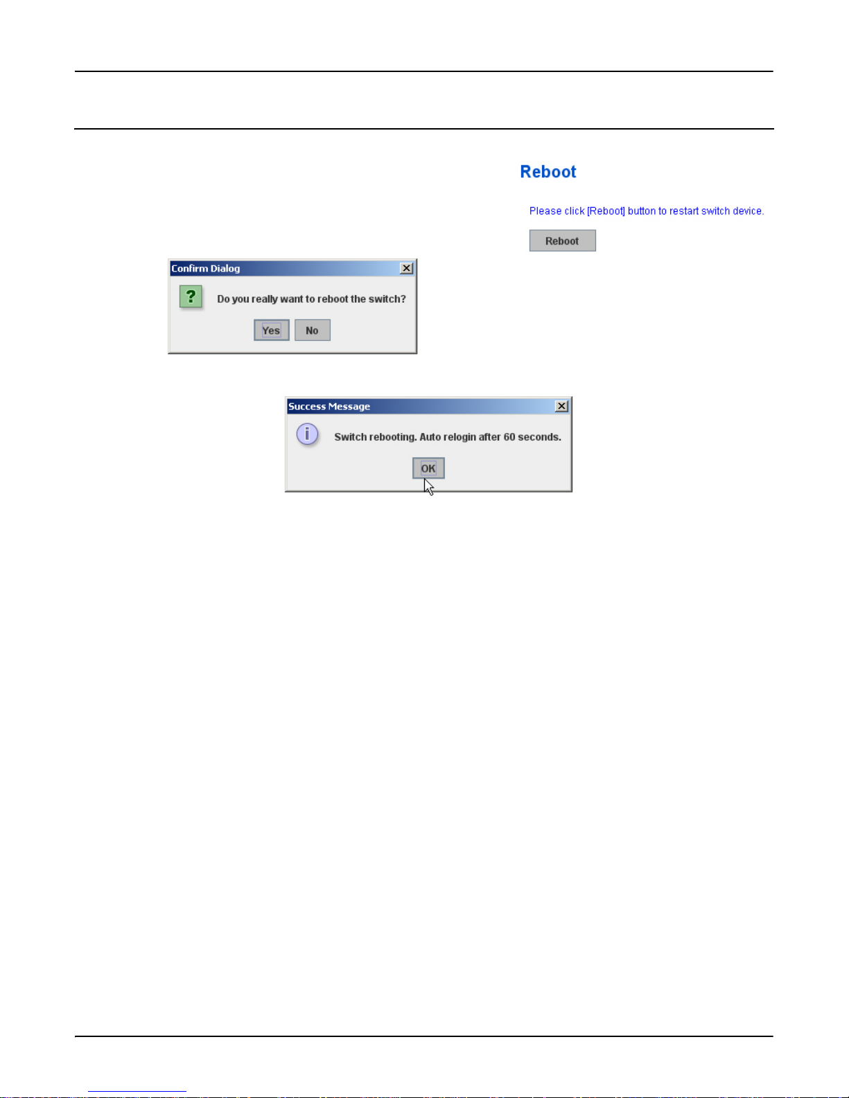
System Reboot
System Reboot allows you to reboot the device. Some of the feature changes
require you to reboot the system. Click Reboot to reboot your device.
Note: Before rebooting, remember to click Save to save your settings.
Otherwise, the settings you are lost when the RocketLinx ES7528 is
powered off.
Click Yes. The switch reboots immediately.
Click Ok so that the RocketLinx ES7528 reboots.
System Reboot
System Reboot RocketLinx ES7528 Industrial Managed PoE Rack Mount User Guide: 2000509 Rev. A - 41
Page 42

CLI Commands for Basic Setting
CLI Commands for Basic Setting
This table provides detailed information about the CLI commands for basic settings.
Feature Command Line
Switch Setting
System Name Switch(config)# hostname
WORD Network name of this system
Switch(config)# hostname ES7528
Switch(config)#
System Location Switch(config)# snmp-server location Minnesota
System Contact Switch(config)# snmp-server contact [email protected]
Display Switch# show snmp-server name
ES7528
Switch# show snmp-server location
Roseville
Switch# show snmp-server contact
[email protected]
Switch> show version
Loader Version : 0.3.0.9
Firmware Version : 1.0-20100930-15:49:56
Hardware Version : 0.1
CPLD Version : 0.1
Switch# show hardware mac
MAC Address: 00C04E320001
Admin Password
User Name and Password Switch(config)# administrator
NAME Administrator account name
Switch(config)# administrator admin
PASSWORD Administrator account password
Switch(config)# administrator admin admin
Change administrator account admin and password admin
success.
Display Switch# show administrator
Administrator account information
name: admin
password: admin
42 - RocketLinx ES7528 Industrial Managed PoE Rack Mount User Guide: 2000509 Rev. A CLI Commands for Basic Setting
Page 43

IP Configuration
CLI Commands for Basic Setting
IP Address/Mask
(192.168.250.250,
255.255.255.0
Note: The enabled bit of the
subnet mask is used to
represent the number
displayed in the web
interface. For example,
8 represents: 255.0.0.0,
Switch(config)# int vlan 1
Switch(config-if)# ip
address
dhcp
Switch(config-if)# ip address 192.168.250.8/24
Switch(config-if)# ip dhcp client
Switch(config-if)# ip dhcp client renew
16 represents:
255.255.0.0,
24
represents:255.255.255.
0.
Gateway Switch(config)# ip route 0.0.0.0/0 192.168.250.254/24
Remove Gateway Switch(config)# no ip route 0.0.0.0/0 192.168.250.254/24
Display Switch# show running-config
………
!
interface vlan1
ip address 192.168.250.8/24
no shutdown
!
ip route 0.0.0.0/0 192.168.250.254/24
!
Time Setting
NTP Server Switch(config)# ntp peer
enable
disable
primary
secondary
Switch(config)# ntp peer primary
IPADDR
Switch(config)# ntp peer primary 192.168.250.250
Time Zone Switch(config)# clock timezone 26
Sun Jan 1 04:13:24 2006 (GMT) Greenwich Mean Time: Dublin,
Edinburgh, Lisbon, London
Note: By typing clock timezone?, you can see the timezone list. Then choose the number
of the timezone you want to select.
IEEE 1588 Switch(config)# ptpd run
<cr>
preferred-clock Preferred Clock
slave Run as slave
CLI Commands for Basic Setting RocketLinx ES7528 Industrial Managed PoE Rack Mount User Guide: 2000509 Rev. A - 43
Page 44

CLI Commands for Basic Setting
Time Setting
Display Switch # sh ntp associations
Network time protocol
Status: Disabled
Primary peer: N/A
Secondary peer: N/A
Switch # show clock
Sun Jan 1 04:14:19 2006 (GMT) Greenwich Mean Time: Dublin,
Edinburgh, Lisbon, London
Switch # show clock timezone
clock timezone (26) (GMT) Greenwich Mean Time: Dublin,
Edinburgh, Lisbon, London
Switch# show ptpd
PTPd is enabled
Mode: Slave
Jumbo Frame
Jumbo Frame Switch(config)# system mtu jumbo
<1500-9216>
Switch(config)# system mtu jumbo 9000
DHCP Server
DHCP Server configuration Enable DHCP Server on RocketLinx ES7528 Switch
Switch#
Switch# configure terminal
Switch(config)# router dhcp
Switch(config-dhcp)# service dhcp
Configure DHCP network address pool
Switch(config-dhcp)#network 50.50.50.0/4 -(network/mask)
Switch(config-dhcp)#default-router 50.50.50.1
Lease time configure Switch(config-dhcp)#lease 300 (300 sec)
DHCP Relay Agent Enable DHCP Relay Agent
Switch#
Switch# configure terminal
Switch(config)# router dhcp
Switch(config-dhcp)# service dhcp
Switch(config-dhcp)# ip dhcp relay information option
Enable DHCP Relay policy
Switch(config-dhcp)# ip dhcp relay information policy
replace
drop Relay Policy
keep Drop/Keep/Replace option 82 field replace
44 - RocketLinx ES7528 Industrial Managed PoE Rack Mount User Guide: 2000509 Rev. A CLI Commands for Basic Setting
Page 45

DHCP Server (cont.)
Show DHCP server information Switch# show ip dhcp server statistics
DHCP Server ON
Address Pool 1
network:192.168.17.0/24
default-router:192.168.17.254
lease time:300
Excluded Address List
IP Address
-------------- (list excluded address)
Manual Binding List
IP Address MAC Address
--------------- -------------(list IP & MAC binding entry)
Leased Address List
IP Address MAC Address Leased Time Remains
--------------- -------------- -------------------(list leased Time remain information for each entry)
CLI Commands for Basic Setting
Backup and Restore
Backup Startup Configuration
file
Switch# copy startup-config tftp: 192.168.250.33/
default.conf
Writing Configuration [OK]
Note: To backup the latest startup configuration file, you should save current settings to
flash first. You can refer to Save to Flash
to the flash.
on Page 137 to see how to save settings
In the example above, 192.168.250.33 is the TFTP server’s IP and default.conf is
name of the configuration file. Your environment may use different IP addresses
or different file name. Type target TFTP server IP or file name in this command.
Restore Configuration Switch# copy tftp: 192.168.250.33/default.conf startup-
config
Show Startup Configuration Switch# show startup-config
Show Running Configuration Switch# show running-config
CLI Commands for Basic Setting RocketLinx ES7528 Industrial Managed PoE Rack Mount User Guide: 2000509 Rev. A - 45
Page 46

CLI Commands for Basic Setting
Firmware Upgrade
Firmware Upgrade Switch# archive download-sw /overwrite tftp 192.168.250.33
ES7528.bin
Firmware upgrading, don't turn off the switch!
Tftping file ES7528.bin
Firmware upgrading
...........................................................
.....................
...........................................................
.....................
...........................
Firmware upgrade success!!
Rebooting.......
Factory Default
Factory Default Switch# reload default-config file
Reload OK!
Switch# reboot
System Reboot
Reboot Switch# reboot
46 - RocketLinx ES7528 Industrial Managed PoE Rack Mount User Guide: 2000509 Rev. A CLI Commands for Basic Setting
Page 47
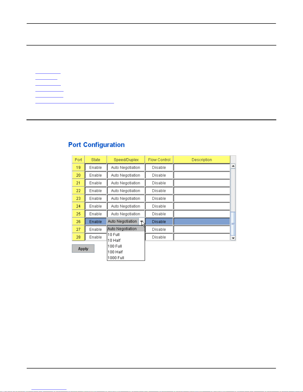
Port Configuration
Port Configuration
Port Configuration group enables you to enable/disable port state, or configure port auto-negotiation, speed, duplex, flow
control, rate limit control, and port aggregation settings. It also allows you to view port status and aggregation information.
The following commands are included in this group:
• Port Control
• Port Status on Page 49
• Rate Control
• Storm Control
• Port Trunking
• Command Lines for Port Configuration
Port Control
Port Control commands allow you to enable/disable port state, or configure the port auto-negotiation, speed, duplex, and flow
control.
on Page 50
on Page 51
on Page 52
on Page 54
Select the port you want to configure and make changes to the port The following table provides information about this page.
Port Configuration RocketLinx ES7528 Industrial Managed PoE Rack Mount User Guide: 2000509 Rev. A - 47
Page 48

Port Control
Technical Tip:
If both ends are not at the same speed, they cannot link with each other. If both ends are not in the
same duplex mode, they are connected by half-duplex mode.
Port Configuration Description
State You can enable or disable the state of this port. Once you click Disable, the
port stops to link to the other end and stops to forward any traffic. The default
setting is Enable which means all the ports are workable when you receive
the RocketLinx ES7528.
Speed/Duplex You can configure port speed and duplex mode of this port. Below are the
selections you can choose:
• Fast Ethernet Port 1~24 (fa1~fa24)
- Auto Negotiation
- 10M full-duplex (10 Full)
- 10M half-duplex (10 Half)
- 100M full-duplex (100 Full)
- 100M half-duplex (100 Half)
- Gigabit Ethernet Port 25~28: (gi25~gi28Auto Negotiation
- 10M full-duplex (10 Full)
- 10M half-duplex (10 Half)
- 100M full-duplex (100 Full)
- 100M half-duplex (100 Half)
- 1000M full-duplex (1000 Full)
Note: The default mode is Auto Negotiation mode.
Flow Control Symmetric means that you need to activate the flow control function of the
remote network device in order to let the flow control of that corresponding
port on the switch to work.
Disable means that you do not need to activate the flow control function of
the remote network device, as the flow control of that corresponding port on
the switch works.
Description Click this field and optionally enter a port description.
Apply Click Apply to apply the settings.
Note: You must Save the settings (Page 137), if you want to maintain these
settings if the RocketLinx ES7528 is powered off.
48 - RocketLinx ES7528 Industrial Managed PoE Rack Mount User Guide: 2000509 Rev. A Port Control
Page 49
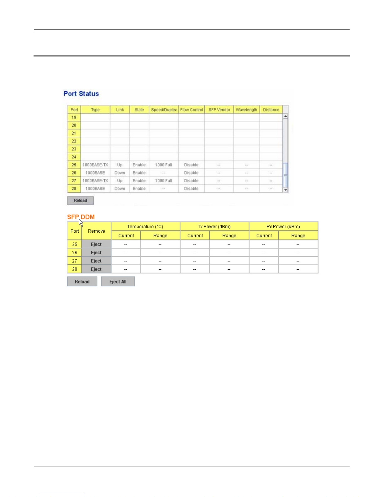
Port Status
Port Status
The Port Status page displays the current port status, including Small Form Factory (SFP) fiber transceiver with Digital
Diagnostic Monitoring (DDM) function that provides real time information of SFP transceiver and allows you to diagnostic
the optical fiber signal received and launched.
Port Status RocketLinx ES7528 Industrial Managed PoE Rack Mount User Guide: 2000509 Rev. A - 49
Page 50
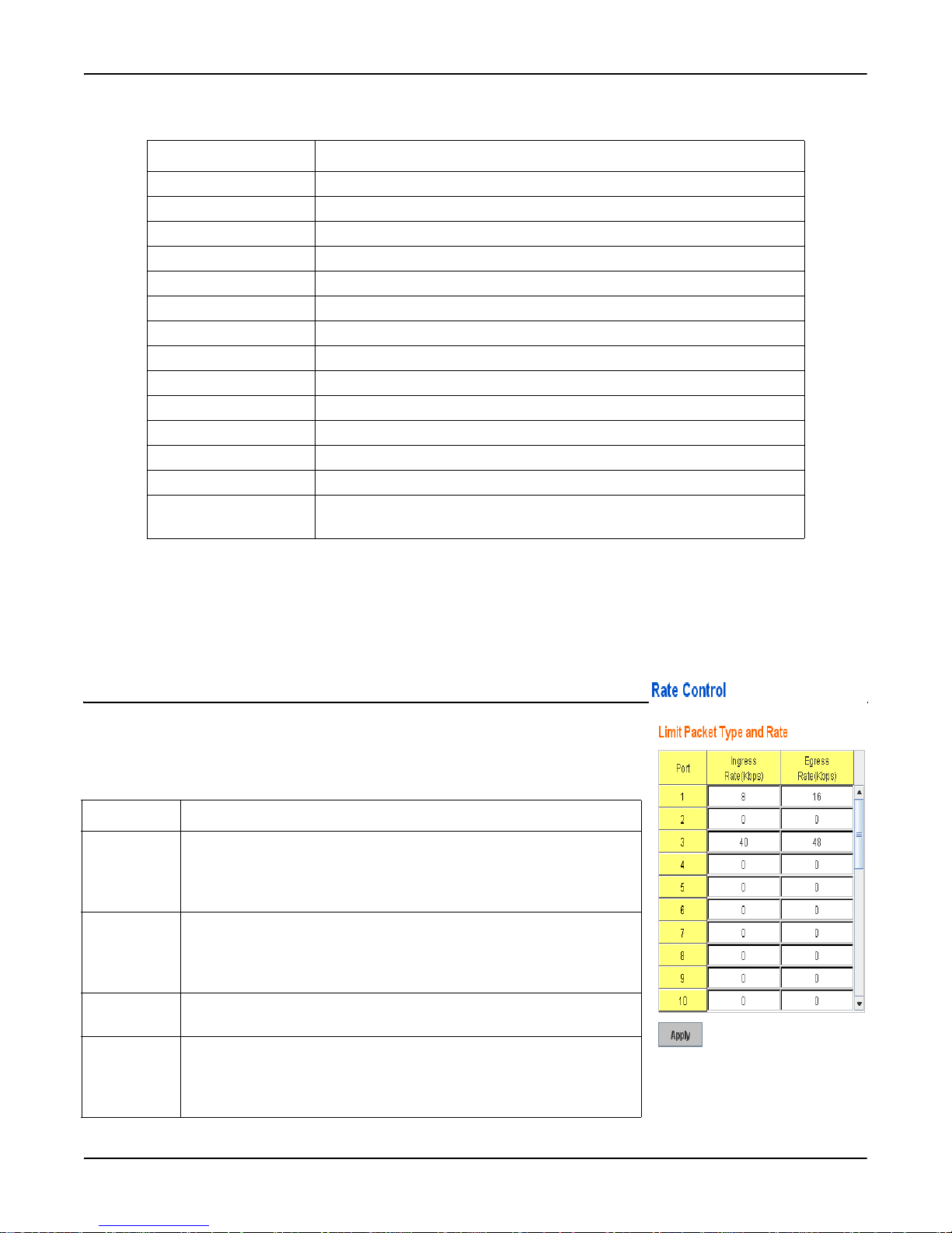
Rate Control
Port Status Description
Port Port interface number.
Type 100BASE-TX -> Fast Ethernet port. 1000BASE-TX -> gigabit Ethernet port.
Link Link status. Up -> Link UP. Down -> Link Down.
State Enable -> State is enabled. Disable -> The port is disable/shutdown.
Speed/Duplex Current working status of the port.
Flow Control The state of the flow control.
SFP Vendor Vendor name of the SFP transceiver that is plugged into the port.
Wavelength The wave length of the SFP transceiver that is plugged into the port.
Distance The distance of the SFP transceiver that is plugged into the port.
Temperature The temperature specific and current detected of DDM SFP transceiver.
Tx Power (dBm) The specification and current transmit power of DDM SFP transceiver.
Rx Power (dBm) The specification and current received power of DDM SFP transceiver.
Reload Click to reload the port status.
Eject/Eject All Eject the DDM SFP transceiver. You can eject one port or eject all by click-
ing Eject All.
Note: Most of the SFP transceivers provide vendor information which allows the RocketLinx ES7528 to read it. The user
interface can display vendor name, wave length, and distance of all Comtrol SFP transceiver models. If you see
Unknown info, it may mean that the vendor does not provide their information or tha t the information of their
transceiver cannot be read.
If the plugged DDM SFP transceiver is not certified by Comtrol, the DDM function is not supported, but the
communication is not disabled.
Rate Control
Rate limiting is a form of flow control used to enforce a strict bandwidth limit at a port.
You can program separate transmit (Egress Rule) and receive (Ingress Rule) rate limits at
each port, and even apply the limit to certain packet types as described below. You can
increment the volume step by 64Kbps in the blank.
Rate Control Description
Limit Packet
Type
Bandwidth The ports support port ingress and egress rate control. For example,
Ingress Ingress rate in Kbps, the rate range is from 1000 Kbps to 1000000 Kbps
Egress Egress rate in Kbps, the rate range is from 1000 Kbps to 1000000 Kbps
The packet types all types of packets, broadcast/multicast/unknown
unicast packets, broadcast/multicast packets, and broadcast packets
only.The ingress rate supports all types of packets. The egress rate
supports all types of packets.
assume that Port 1 is 10000 Kbps, you can set it's effective egress rate at
2000 Kbps, ingress rate is 1000 Kbps. The switch performs the ingress
rate by packet counter to meet the specified rate.
and zero means no limit. The default value is no-limit.
and zero means no limit. The default value is no-limit. Egress rate limiting has an effect on all types of packets, including unicast, multicast, and
broadcast packets.
50 - RocketLinx ES7528 Industrial Managed PoE Rack Mount User Guide: 2000509 Rev. A Rate Control
Page 51
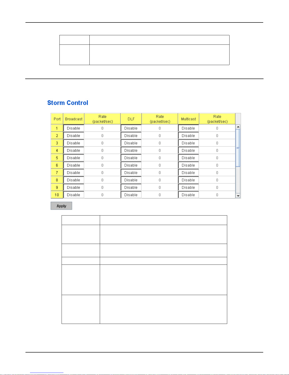
Storm Control
Rate Control Description
Apply Click Apply to apply the settings.
Note: You must Save the settings (Page 137), if you want to maintain
these settings if the RocketLinx ES7528 is powered off.
Storm Control
The Storm Control is similar to Rate Control. Rate Control filters all the traffic over the threshold you input by the user
interface. Storm Control allows you to define the rate for specific Packet Types.
Storm Control Description
Broadcast To enable or disable broadcast storm control on this port.
Choose Enable/Disable to enable or disable the storm control of
specific port.
DLF To enable or disable destination lookup failure storm control on
this port.
Multicast To enable or disable multicast storm control on this port.
Rate (packet/sec) These columns allow you to manually assign the limit rate of the
port. The unit is packets per second. The limit range is from 1 to
262143 packet/sec, zero means no limit. The maximum available
value of Fast Ethernet interface is 148810, this is the maximum
packet number of the 100M throughput.
Apply Click Apply to apply the settings. It may take some time and the
web interface may become slow, this is normal condition.
Note: You must Save the settings (Page 137), if you want to
maintain these settings if the RocketLinx ES7528 is
powered off.
Storm Control RocketLinx ES7528 Industrial Managed PoE Rack Mount User Guide: 2000509 Rev. A - 51
Page 52
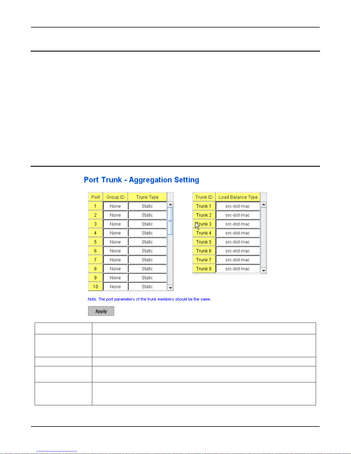
Port Trunking
Port Trunking
Port Trunking configuration allows you to group multiple Ethernet ports in parallel to increase link bandwidth. The aggregated
ports can be viewed as one physical port so that the bandwidth is higher than merely one single Ethernet port.The member
ports of the same trunk group can balance the loading and backup for each other. The Port Trunking feature is usually used
when you need higher bandwidth for the network backbone. This is an inexpensive way for you to transfer more data.
There are some different descriptions for the port trunking. Different manufacturers may use different descriptions for their
products, like Link Aggregation Group (LAG), Link Aggregation Control Protocol, Ethernet Trunk, or Ether Channel.
The aggregated ports can interconnect to the other switch, which also supports Port Trunking. Comtrol supports two types of
port trunking:
• Static Trunk
• 802.3ad
When the other end uses 802.3ad LACP, you should assign 802.3ad LACP to the trunk. When the other end uses non-802.3ad,
you can then use Static Trunk.
There are two pages for port trunking, Aggregation Setting and Aggregation Status.
Aggregation Setting
Aggregation Setting Description
Trunk Size The switch can support up to 8 trunk groups. Each trunk group can support up to 8 member
ports. Since the member ports should use the same speed/duplex, maximum groups for 100M
ports would be 7, and 3 for gigabit ports.
Group ID Group ID is the ID for the port trunking group. Ports with same group ID are in the same group.
Trunk Type Static or 802.3ad LACP. Each Trunk Group can only support Static or 802.3ad LACP. Choose
the type you need here. Non-active ports cannot be setup here.
Load Balance Type There are several load balance types based on dst-ip (Destination IP), dst-mac (Destination
MAC), src-dst-ip (Source and Destination IP), src-dst-mac (Source and Destination MAC), srcip (Source IP), src-mac (Source MAC).
52 - RocketLinx ES7528 Industrial Managed PoE Rack Mount User Guide: 2000509 Rev. A Port Trunking
Page 53
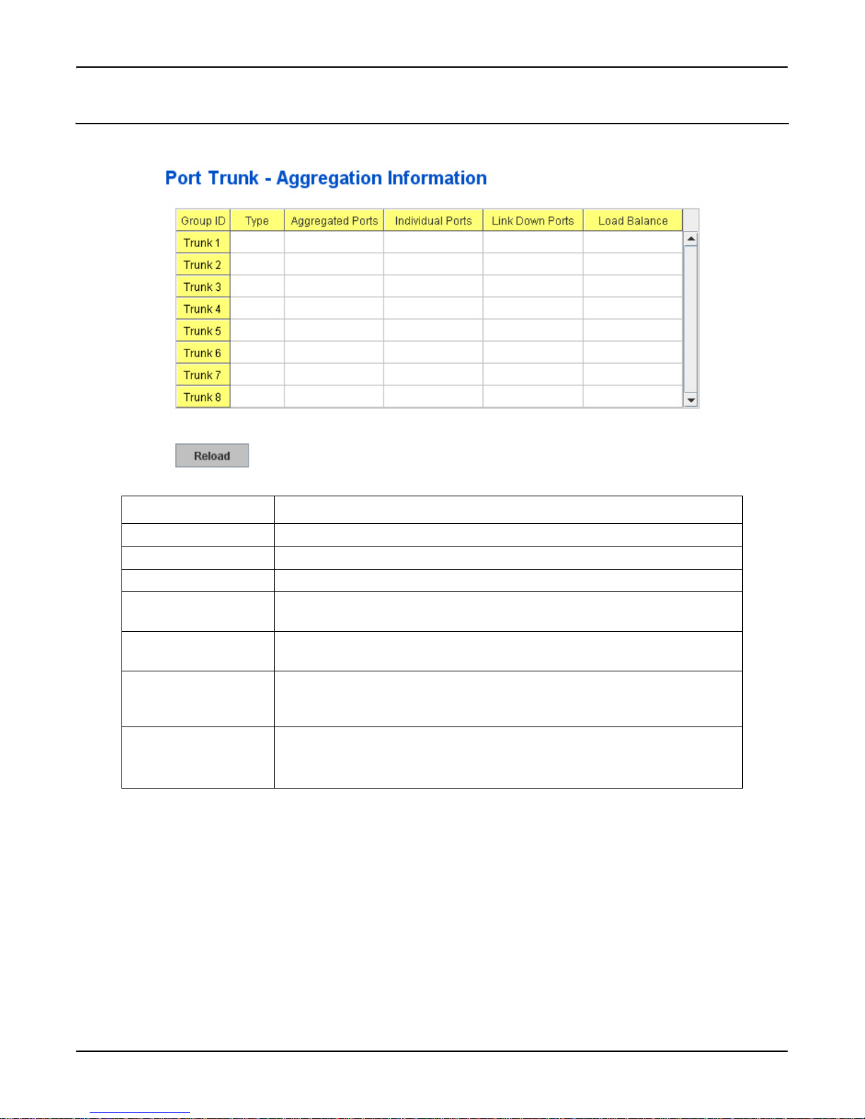
Aggregation Status
Aggregation Status
This page shows the status of port aggregation. Once the aggregation ports are negotiated, you will see the following status.
Aggregation Status Description
Group ID Displays Trunk 1 to Trunk 8 set up.
Type Static or LACP set up.
Aggregated Ports When LACP links, you can see the member ports in the Aggregated column.
Individual Ports When LACP is enabled, member ports of LACP group that are not connected to
the correct LACP member ports are displayed in the Individual column.
Link Down Ports When LACP is enabled, member ports of LACP group that are not linked up are
displayed in the Link Down column.
Load Balance There are several load balance types based on dst-ip (Destination IP), dst-mac
(Destination MAC), src-dst-ip (Source and Destination IP), src-dst-mac (Source
and Destination MAC), src-ip (Source IP), src-mac (Source MAC).
Apply Click Apply to apply the settings.
Note: You must Save the settings (Page 137), if you want to maintain these
settings if the RocketLinx ES7528 is powered off.
Aggregation Status RocketLinx ES7528 Industrial Managed PoE Rack Mount User Guide: 2000509 Rev. A - 53
Page 54

Command Lines for Port Configuration
Command Lines for Port Configuration
This table provides detailed information about the CLI commands for port configuration.
Feature Command Line
Port Control
Port Control –
State
Port Control –
Auto
Negotiation
Port Control –
Force Speed/
Duplex
Switch(config-if)# shutdown -> Disable port state
Port1 Link Change to DOWN
interface fastethernet1 is shutdown now.
Switch(config-if)# no shutdown -> Enable port state
Port1 Link Change to DOWN
Port1 Link Change to UP
interface fastethernet1 is up now.
Switch(config-if)# Port1 Link Change to UP
Switch(config)# sfp
ddm Digital diagnostic and monitoring
Switch(config)# sfp ddm
Eject Reject DDM SFP
Switch(config)# sfp ddm eject eject SFP DDM transceiver
all All DDM interface
Example: Switch(config)# sfp ddm eject all
DDM SFP on Port 9 normally ejected.
DDM SFP on Port 9 normally ejected.
All DDM SFP normally ejected.
Switch(config)# interface gigabitethernet10 eject port 10 SFP DDM
transceiver.
Switch(config-if)# sfp ddm eject
DDM SFP on Port 10 normally ejected.
Switch(config)# interface fa1
Switch(config-if)# auto-negotiation
Auto-negotiation of port 1 is enabled!
Switch(config-if)# speed 100
Port1 Link Change to DOWN
set the speed mode ok!
Switch(config-if)# Port1 Link Change to UP
Switch(config-if)# duplex full
Port1 Link Change to DOWN
set the duplex mode ok!
Switch(config-if)# Port1 Link Change to UP
54 - RocketLinx ES7528 Industrial Managed PoE Rack Mount User Guide: 2000509 Rev. A Command Lines for Port Configuration
Page 55

Port Control (continued)
Command Lines for Port Configuration
Port Control –
Flow Control
Switch(config-if)# flowcontrol on
Flowcontrol on for port 1 set ok!
Switch(config-if)# flowcontrol off
Flowcontrol off for port 1 set ok!
Port Status
Port Status Switch# show interface fa1
Interface fastethernet1
Administrative Status : Enable
Operating Status : Connected
Duplex : Full
Speed : 100
Flow Control :off
Default Port VLAN ID: 1
Ingress Filtering : Disabled
Acceptable Frame Type : All
Port Security : Disabled
Auto Negotiation : Disable
Loopback Mode : None
STP Status: forwarding
Default CoS Value for untagged packets is 0.
Mdix mode is Disable.
Medium mode is Copper.
Switch# show sfp ddm show SFP DDM information
Port 8
Temperature:N/A
Tx power:N/A
Rx power:N/A
Port 9
Temperature:64.00 C <range :0.0-80.00>
Tx power:-6.0 dBm <range : -9.0 - -4.0>
Rx power:-30.0 dBm <range: -30.0 - -4.0>
Port 10
Temperature:67.00 C <range :0.0-80.00>
Tx power:-6.0 dBm <range : -9.0 - -4.0>
Rx power:-2.0 dBm <range: -30.0 - -4.0>
Note: Administrative Status -> Port state of the port. Operating status -> Current status of the port. Duplex
-> Duplex mode of the port. Speed -> Speed mode of the port. Flow control -> Flow Control status
of the port.
Command Lines for Port Configuration RocketLinx ES7528 Industrial Managed PoE Rack Mount User Guide: 2000509 Rev. A - 55
Page 56

Command Lines for Port Configuration
Rate Control
Rate Control –
Ingress or
Egress
Rate Control –
Filter Packet
Type
Rate Control –
Bandwidth
Storm Contro l
Storm Control
– Packet Type
Storm Control
- Rate
Switch(config-if)# rate-limit
egress Outgoing packets
ingress Incoming packets
Note: To enable rate control, you should select the Ingress or Egress rule first; then assign the packet type
and bandwidth.
Switch(config-if)# rate-limit ingress mode
all Limit all frames
broadcast Limit Broadcast frames
flooded-unicast Limit Broadcast, Multicast and flooded unicast frames
multicast Limit Broadcast and Multicast frames
Switch(config-if)# rate-limit ingress mode broadcast
Set the ingress limit mode broadcast ok.
Switch(config-if)# rate-limit ingress bandwidth
<0-100> Limit in megabits per second (0 is no limit)
Switch(config-if)# rate-limit ingress bandwidth 8
Set the ingress rate limit 8Mbps for Port 1.
Switch(config-if)# storm-control
broadcast :Broadcast packets
dlf :Destination Lookup Failure
multicast :Multicast packets
Switch(config)# storm-control broadcast
<0-100000> Rate limit value 0~262143 packet/sec
Switch(config)# storm-control broadcast 10000
limit_rate = 10000 packets/sec
Set rate limit for Broadcast packets.
Switch(config)# storm-control multicast 10000
limit_rate = 10000 packets/sec
Set rate limit for Multicast packets.
Switch(config)# storm-control dlf 10000
limit_rate = 10000 packets/sec
Set rate limit for Destination Lookup Failure packets.
Port Trunking
LACP Switch(config)# lacp group 1 25-28
Group 1 based on LACP(802.3ad) is enabled!
Note: The interface list is fa1,fa3-5, and gi25-28. Ports with a different speeds cannot be aggregated
together.
Static Trunk Switch(config)# trunk group 2 fa6-7
Trunk group 2 enable ok!
56 - RocketLinx ES7528 Industrial Managed PoE Rack Mount User Guide: 2000509 Rev. A Command Lines for Port Configuration
Page 57

Port Trunking (cont.)
Command Lines for Port Configuration
Display –
LACP
Display –
Trunk
Switch# show lacp internal
LACP group 1 internal information:
LACP Port Admin Oper Port
Port Priority Key Key State
----- ----------- -------- -------- ------ 8 1 8 8 0x45
9 1 9 9 0x45
10 1 10 10 0x45
LACP group 2 is inactive
LACP group 3 is inactive
LACP group 4 is inactive
Switch# show trunk group 1
FLAGS: I -> Individual P -> In channel
D -> Port Down
Trunk Group
GroupID Protocol Ports
--------+---------+----------------------------------- 1 LACP 8(D) 9(D) 10(D)
Switch# show trunk group 2
FLAGS: I -> Individual P -> In channel
D -> Port Down
Trunk Group
GroupID Protocol Ports
--------+---------+----------------------------------- 2 Static 6(D) 7(P)
Switch#
Command Lines for Port Configuration RocketLinx ES7528 Industrial Managed PoE Rack Mount User Guide: 2000509 Rev. A - 57
Page 58
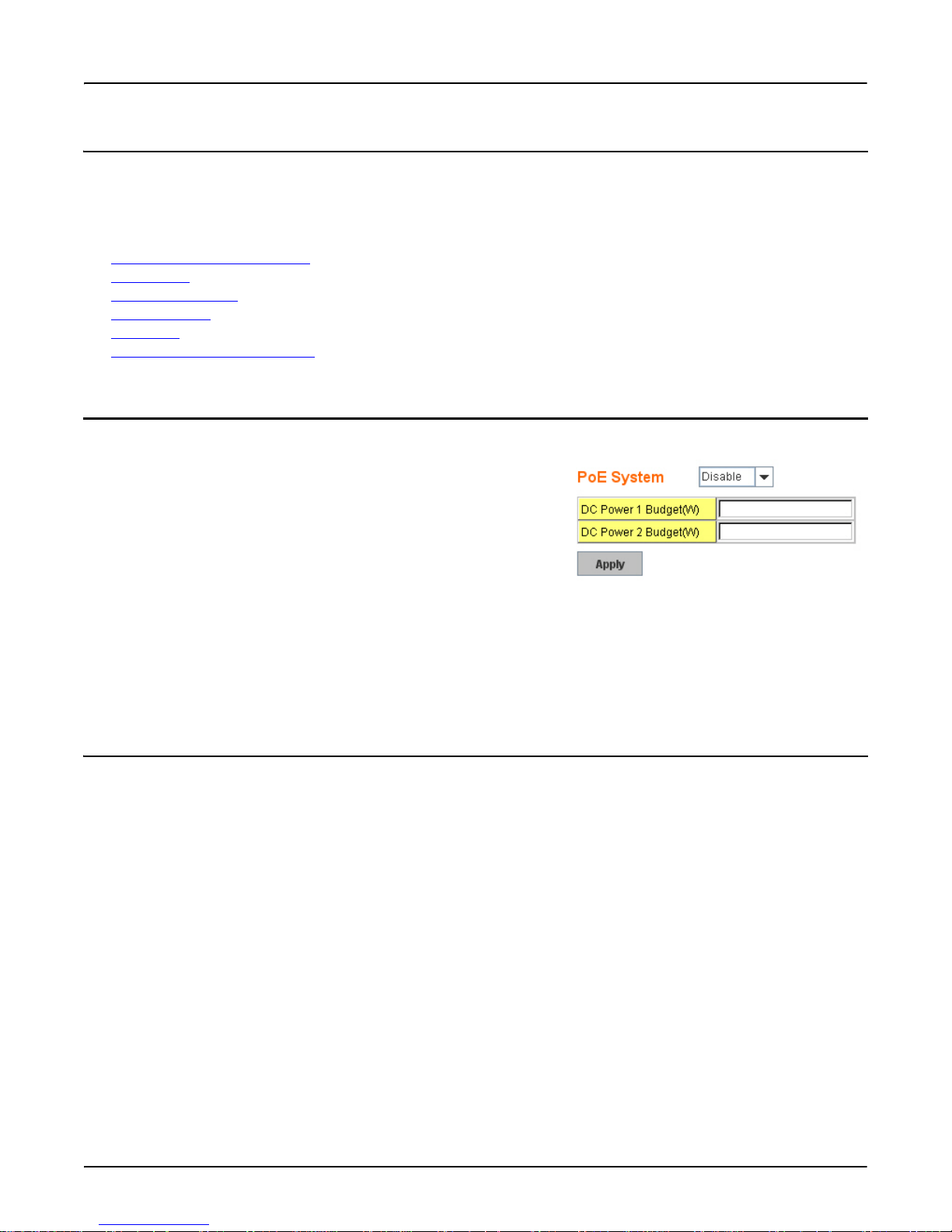
Power over Ethernet
Power over Ethernet
Power over Ethernet is one of the key features of RocketLinx ES7528. It is fully IEEE802.3af-2003 compliant, and supports
IEEE802.3at, including two-event and LLDP classification. The RocketLinx ES7528 supports up to 24-Port PoE injectors in
Port 1 to Port 24, each port with the ability to deliver 606 mA current.
The following commands are included in this section:
• Emergency Power Management
• PoE Control
• PD Status Detection on Page 60
• PoE Scheduling
• PoE Status
• Command Line for PoE Control
Emergency Power Management
The RocketLinx ES7528 provides dual 48VDC power inputs for providing
true network redundancy. An alarm relay output signals when a power input
fails or other critical events occur. To ensure reliable power delivery, other
advanced PoE power management features include individual port status
monitoring, emergency power management (three power supply indication
inputs for quick shutdown of ports according to pre-defined priority table in
cases where power supply failure occurs) and voltage/current monitoring
and regulation. Power management allows the RocketLinx ES7528 to
determine the exact power draw per port and to balance each port PoE
power output accordingly. This allows the switch to power higher and lower
wattage devices according to user-definable parameters such as maximum available power, port priority (critical, high, low),
and maximum allowable power per port. For the same level priority, the priority order is decided by port number. The port
number sequence is from high priority to low priority is 3-4-1-2-7-8-5-6-11-12-9-10-15-16-13-14-19-20-17-18-23-24-21-2227-28-25-26.
You can configure the power budget of DC Power 1 and 2 by following the Web UI. The valid range of budget is 1 – 480
Watts. The default power budget of inside AC power supply is 300W.
on Page 61
on Page 61
on Page 62
PoE Control
In WiMax systems, Wireless applications, and high-end PoE applications, there are various types of PDs, for example, IEEE
802.3af, IEEE 802.3at two-event, IEEE 802.3at LLDP, and non-standard type. To be compatible with different PDs, the
RocketLinx ES7528 is designed with four powering modes, including IEEE 802.3af mode, IEEE 802.3at 2-event mode and,
IEEE 802.3at LLDP classification mode as well as forced powering mode to meet all of the PD types in the industry. As a
result, they can be flexibly used to deliver power for different PoE-enabled devices in various applications.
IEEE 802.3at LLDP provides smart power budget control behavior to fulfill the needs of higher end setups requiring exact
high power delivery. By using the ongoing dynamic re-negotiation function of the IEEE802.3at LLDP, the RocketLinx ES7528
can perform more intelligently by dynamically reallocating power to the PDs. The RocketLinx ES7528 implements the 2 event
and Link Layer Discovery Protocol (LLDP) PoE into the system for efficient power budget negotiation between PSE and PD
devices.
58 - RocketLinx ES7528 Industrial Managed PoE Rack Mount User Guide: 2000509 Rev. A Power over Ethernet
Page 59
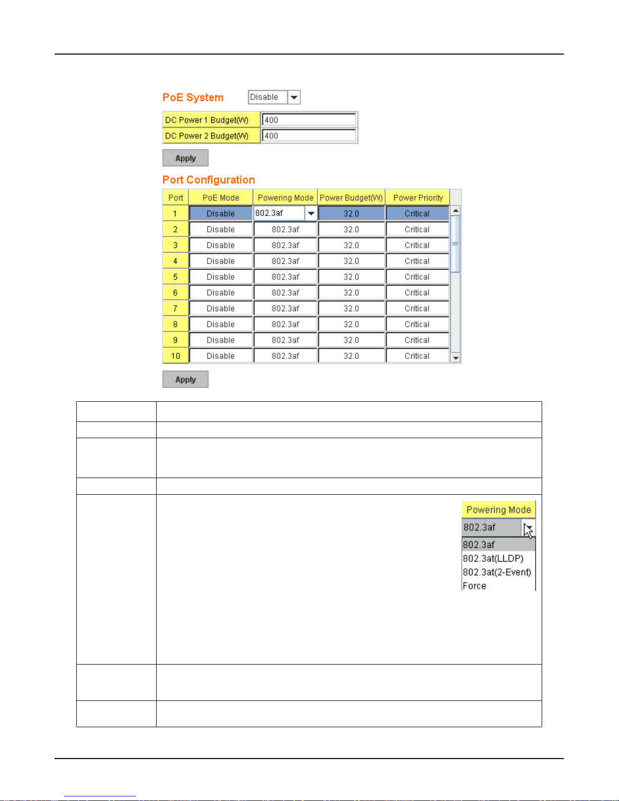
The following figure shows the Web UI interface for Power over Ethernet Control.
PoE Control
PoE Control Description
PoE System Use this column to Enable/Disable ports, or set it to scheduling control mode.
DC Power 1
The limitation of output power in watts. The range is 1- 480.
DC Power 2
Budget (W)
PoE Mode You can select Disable, Enable, or Schedule for the PoE mode for each port.
Powering Mode Use this mode to change the Powering Mode to one of the following:
• IEEE 802.3af
• 802.3at(LLDP)
• 802.3at(2-Event)
•Force
When the column is IEEE 802.3af, if and only if the PD follows IEEE
802.3af, then the RocketLinx ES7528 could deliver the power. If the
Powering mode is 802.3at(LLDP) or 802.3at(2-Event), the RocketLinx
ES7528 would deliver power to the PD that supports IEEE 802.3at
LLDP or 2-Event feature. If the Powering Mode changes to Force mode, once the PoE mode is
enabled, the port directly delivers the power even there is no Ethernet cable connected.
Note: Use caution when usi ng Force mode.
Power Budget
(W)
The Power Budget can limit the consumption of PoE and ensure the PoE port can get the pre-
allocated power budget. The range of Power Budget is 0.4 to 32 Watt. The maximum effective
power budget of 802.3af powering mode is 15.4 W even if the power budget is set to 32 W.
Power Priority Power Priority lets the PoE port with higher priority to deploy power under the limit power
budget. There are three priorities (Critical, High and Low).
PoE Control RocketLinx ES7528 Industrial Managed PoE Rack Mount User Guide: 2000509 Rev. A - 59
Page 60
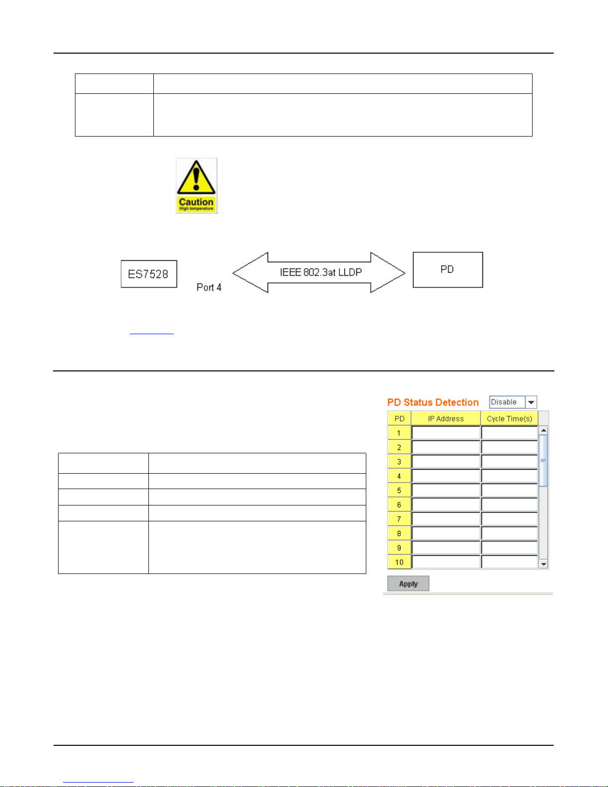
PD Status Detection
DO NOT TOUCH DEVICE SURFACE DURING
PoE PROGRESS HIGH POWER FEEDING.
PoE Control Description
Apply Click Apply to apply the settings.
Note: You must Save the settings (Page 137), if you want maintain these settings if the
RocketLinx ES7528 is powered off.
The following graphic illustrates how to configure IEEE 802.3at LLDP. Assume the PD is ready for the configuration for IEEE
802.3at LLDP, you only need to confirm the RocketLinx ES7528 configuration.
For example, connect the port of the RocketLinx ES7528 to the PD (ex. Port 4), set PoE Mode is Enable and Powering Mode
is 802.3at(LLDP). When the RocketLinx ES7528 and the PD are ready to IEEE802.3at LLDP, IEEE 802.3at LLDP starts
operation. Refer to PoE Status
on Page 61, to see the PoE Status page.
PD Status Detection
The RocketLinx ES7528 delivers a useful function – PD Status Detection. This
provides automatic detection of a remote device powered by the RocketLinx
ES7528. If the remote system crashes or is unstable, the RocketLinx ES7528
performs a system reboot by turning off and on again to trigger the remote
device. The following figure shows the web configuration interface for Power
over Ethernet PD Status Detection.
PD Status Detection Description
PD Status Detection Enable/Disable PD Status Detection function.
IP Address Type in the IP address that you want to detect.
Cycle Time(s) This is the gap per detection in seconds.
Apply Click Apply to apply the settings.
Note: You must Save the settings (Page 137), if you
want maintain these settings if the
RocketLinx ES7528 is powered off.
60 - RocketLinx ES7528 Industrial Managed PoE Rack Mount User Guide: 2000509 Rev. A PD Status Detection
Page 61
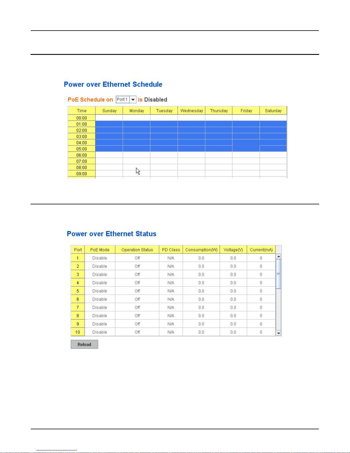
PoE Scheduling
PoE Scheduling
The PoE Scheduling control is a powerful function to help you save power and money. You need to configure PoE Scheduling
and select a target port manually to enable this function.
PoE Status
The PoE Status page shows the operating status of each PoE Port. The information includes PoE mode, Operation status, PD
class, Power Consumption, Voltage and Current.
PoE Scheduling RocketLinx ES7528 Industrial Managed PoE Rack Mount User Guide: 2000509 Rev. A - 61
Page 62

Command Line for PoE Control
Command Line for PoE Control
This table provides detailed information about the CLI commands for PoE control.
Syntax show poe system
Parameters --
Command Mode Enable mode
Description Display the status of the PoE system.
Examples Switch> enable
Switch# show poe system
PoE System
PoE Admin : Enable
PoE Hardware : Normal
PoE Input Voltage :
Vmain 1 : 52.8 V
Vmain 2 : 53.0 V
Vmain 3 : 52.5 V
Ouput power : 0.0 Watts
Temperature 1 : 39 degree
Temperature 2 : 41 degree
Temperature 3 : 47 degree
Power information :
Budget :
DC Power 1 : 400 Watts (In Use)
DC Power 2 : 400 Watts
AC Power : 300 Watts (In Use)
Total : 1100 Watts
700 Watts in Use
Warning water level : N/A
Utilization : 0 %
Event : Normal
62 - RocketLinx ES7528 Industrial Managed PoE Rack Mount User Guide: 2000509 Rev. A Command Line for PoE Control
Page 63

Syntax show poe interface IFNAME
Parameters IFNAME : interface name
Command Mode Enable mode
Description Display the PoE status of interface.
Examples Switch> enable
Switch# show poe interface fa1
Interface fastethernet1 (POE Port 1)
Control Mode : User (Disable)
Powering Mode : 802.3af
Operation Status : Off
Detection Status : Valid
Classification : N/A
Priority : Highest
Output Power : 0.0 Watts, Voltage : 0.0 V, Current : 0 mA
Power Budget :
Budget : 32.0 Watts, effective 0 Watts
Warning water level : N/A
Utilization : 0 %
Event : Normal
Syntax show poe pd_detect
Command Line for PoE Control
Parameters --
Command Mode Enable mode
Description Display the status of pd status detection.
Examples Switch# show poe pd-detect
PD Status Detection
Status : Enabled
Host 1 :
Target IP : 192.168.250.100
Cycle Time : 10
Host 2 :
Target IP : 192.168.250.200
Cycle Time : 20
Host 3 :
Target IP : 192.168.250.15
Cycle Time : 30
Host 4 :
Target IP : 192.168.250.20
Cycle Time : 40
Command Line for PoE Control RocketLinx ES7528 Industrial Managed PoE Rack Mount User Guide: 2000509 Rev. A - 63
Page 64

Command Line for PoE Control
Syntax show poe schedule IFNAME
Parameters IFNAME : interface name
Command Mode Enable mode
Description Display the status of schedule of interface.
Examples Switch# show poe schedule fa1
Interface fastethernet1
POE Schedule
Status : Disable
Weekly Schedule :
Sunday : 0,1,2,3,4,5,6,7,8,19,20,21,22,23
Monday : 0,1,2,3,4,5,6,7,8,19,20,21,22,23
Tuesday : 0,1,2,3,4,5,6,7,8,19,20,21,22,23
Wednesday : 0,1,2,3,4,5,6,7,8,19,20,21,22,23
Thursday : 0,1,2,3,4,5,6,7,8,19,20,21,22,23
Friday : 0,1,2,3,4,5,6,7,8,19,20,21,22,23
Saturday :
0,1,2,3,4,5,6,7,8,9,10,11,12,13,14,15,16,17,18,19,20
Syntax poe powering-mode 802.3af/forced
Parameters 802.3af: deliver power if and only if the attached PD comply with IEEE 802.3af
forced: deliver power no matter what PD attached
Command Mode Interface mode
Description Set the Powering mode of PoE
Examples EX 1: Set 802.3af powering mode
Switch(config)# poe powering-mode 802.3af
EX 2: Set forced powering mode
Switch(config)# poe powering-mode forced
64 - RocketLinx ES7528 Industrial Managed PoE Rack Mount User Guide: 2000509 Rev. A Command Line for PoE Control
Page 65

Command Line for PoE Control
Syntax poe powering-mode 802.3at 2-event/lldp
Parameters 2-event: deliver power if and only if the attached PD comply with IEEE 802.3at physical layer
classification
lldp: deliver power if and only if the attached PD comply with IEEE 802.3at data link layer
classification
Command Mode Interface mode
Description Set the Powering mode of PoE
Examples EX 1: Set 802.3at 2-event powering mode
Switch(config)# poe powering-mode 802.3at 2-event
EX 2: Set 802.3at lldpforced powering mode
Switch(config)# poe powering-mode 802.3at lldp
Syntax poe control-mode user/schedule
Parameters user: user mode
schedule: schedule mode
Command Mode Interface mode
Description Set the control mode of port
Examples Set PoE port 2 to user mode.
EX 1:
Switch(config)# interface fa2
Switch(config-if)# poe control-mode user
Set PoE port 2 to schedule mode.
EX 2:
Switch(config-if)# poe control-mode schedule
Syntax poe user enable/disable
Parameters enable: enable port in user mode
disable: disable port in user mode
Command Mode Interface mode
Description Enable/Disable the PoE of the port in user mode.
If in schedule mode, it will come into affect when the control mode changes to user mode.
Examples To enable the PoE function in user mode
Switch(config-if)# poe user enable
To disable the PoE function in user mode
Switch(config-if)# poe user disable
Command Line for PoE Control RocketLinx ES7528 Industrial Managed PoE Rack Mount User Guide: 2000509 Rev. A - 65
Page 66

Command Line for PoE Control
Syntax poe type TYPE
Parameters TYPE: port type string with maximum 20 characters
Command Mode Interface mode
Description Set the port type string.
Examples Set the type string to “IPCam-1.
Switch(config-if)# poe type IPCam-1
Syntax poe budget [POWER]
Parameters POWER : 0.4 – 32
Command Mode Interface mode
Description Set the port budget.
The maximum budget is different between 802.3af, 802,3at and forced powering mode.
The maximum budget of 802.3af powering mode is 15.4.
The maximum budget of 802.3at powering mode is 32.
The maximum budget of force powering mode is 32.
Examples Set the maximum value of power consumption to 12 W with manual mode.
Switch(config-if)# poe budget 12
Syntax poe budget warning <0-100>
Parameters <0-100> 0 is disable, valid range is 1 to 100 percentage
Command Mode Interface mode
Description Set the warning water level of port budget.
Examples Set the warning water level to 60%
Switch(config-if)# poe budget warning 60
Syntax poe priority critical/high/low
Parameters Critical : Highest priority level
High : High priority level
Low : Low priority level
Command Mode Interface mode
Description Set the powering priority. The port with higher priority has the privilege to delivery power under
limited power situation.
Examples Set the priority to critical
Switch(config-if)# poe priority critical
66 - RocketLinx ES7528 Industrial Managed PoE Rack Mount User Guide: 2000509 Rev. A Command Line for PoE Control
Page 67

Command Line for PoE Control
Syntax poe schedule weekday hour
Parameters Weekday : Valid range 0-6 (0=Sunday, 1=Monday, …, 6=Saturday)
Hour : Valid range 0-23, Valid format a,b,c-d
Command Mode Interface mode
Description Add a day schedule to an interface.
Examples Add a schedule which enables PoE function at hour 1, 3, 5 and 10 to 23 on Sunday.
Switch(config-if)# poe schedule 0 1,3,5,10-23
Syntax no poe schedule weekday
Parameters Weekday : Valid range 0-6 (0=Sunday, 1=Monday, …, 6=Saturday)
Command Mode Interface mode
Description Remove a day schedule
Examples Remove the Sunday schedule.
Switch(config-if)# no poe schedule 0
Syntax poe budget DC1/DC2 [POWER]
Parameters DC1 : DC 1 power input
DC2 : DC 2 power input
POWER : 1 – 480
Command Mode Configuration mode
Description Set the power budget of DC1 or DC2
Examples Set the power budget of DC1 to 480W
Switch(config)# poe budget DC1 480
Syntax poe budget warning <0-100>
Parameters <0-100> 0 is disable, valid range is 1 to 100 percentage
Command Mode Configuration mode
Description Set the warning water level of total power budget.
Examples Set the warning water level to 60%
Switch(config-if)# poe budget warning 60
Command Line for PoE Control RocketLinx ES7528 Industrial Managed PoE Rack Mount User Guide: 2000509 Rev. A - 67
Page 68
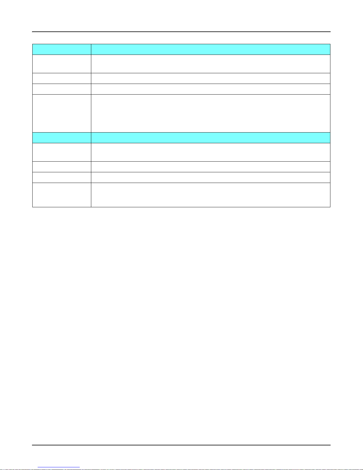
Command Line for PoE Control
Syntax poe pd_detect enable/disable
Parameters enable: enable PD Status Detection function
disable: disable PD Status Detection function
Command Mode Configuration mode
Description Enable/Disable the PD Status Detection function
Examples To enable the function of pd status detect function
Switch(config)# poe pd_detect enable
To disable the function of pd status detect function
Switch(config)# poe pd_detect disable
Syntax poe pd_detect ip_address cycle_time
Parameters IP address : A.B.C.D
Cycle time : Valid range 10-3600 second and must be multiple of 10
Command Mode Configuration mode
Description Apply a rule of PD Status Detection.
Examples Apply a rule which ping 192.160.1.2 per 20 seconds. If 192.160.1.2 is timed out, the PD status
detection is re-enable the PoE.
Switch(config)# poe pd_detect 192.160.1.2 20
68 - RocketLinx ES7528 Industrial Managed PoE Rack Mount User Guide: 2000509 Rev. A Command Line for PoE Control
Page 69
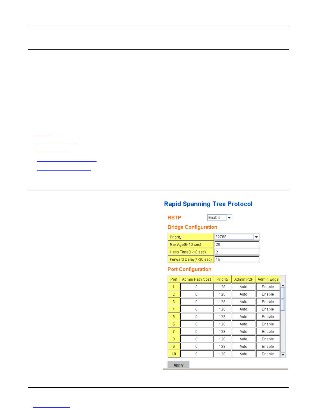
Network Redundancy
Network Redundancy
It is critical for industrial applications that the network remains running at all times. The RocketLinx ES7528 supports:
• Standard Rapid Spanning Tree Protocol (STP and RSTP)
The RocketLinx ES7528 supports RSTP versions 802.1D-2004, 802.1D-1998 STP, and 802.1w RSTP.
• Redundant Ring
Redundant Ring features 0 ms for restore and about 5 ms for fail over for copper.
• Rapid Dual Homing (RDH)
Advanced RDH technology facilitates the RocketLinx ES7528 to connecting with a core managed switch easily and
conveniently. With RDH technology, you can also couple several Rapid Super Rings or RSTP groups together, which is
also known as Auto Ring Coupling.
The following commands are included in this group:
• RSTP
on Page 69
• RSTP Information
• Redundant Ring
• Redundant Ring Information
• Command Lines for RSTP
on Page 71
on Page 72
on Page 74
on Page 75
RSTP
If a switch has more than one path to a destination, it leads to
message loops that can generate broadcast storms and quickly
bog down a network.
The spanning tree was created to combat the negative effects
of message loops in switched networks. A spanning tree uses a
spanning tree algorithm (STA) to automatically sense whether
a switch has more than one way to communicate with a node.
It then selects the best path (primary), and blocks the other
paths. It also keeps track of the blocked paths in case the
primary path fails. Spanning Tree Protocol (STP) introduced a
standard method to accomplish this. It is specified in IEEE
802.1D-1998. Later, Rapid Spanning Tree Protocol (RSTP)
was adopted and represents the evolution of STP, providing
much faster spanning tree convergence after a topology
change. This is specified in IEEE 802.1w. In 2004, 802.1w is
included into the 802.1D-2004 version. This switch supports
both RSTP and STP (all switches that support RSTP are also
backward compatible with switches that support only
STP).This page allows you to enable/disable RSTP, configure
the global setting and port settings.
Network Redundancy RocketLinx ES7528 Industrial Managed PoE Rack Mount User Guide: 2000509 Rev. A - 69
Page 70

RSTP
Rapid Spanning
Tree Protocol
Description
RSTP You must first Enable STP/RSTP mode, before configuring any related parameters. Parameter settings
required for both STP and RSTP are the same. 802.1d refers to STP mode, while 802.1w refers to faster
RSTP mode.
Bridge Configuration
Priority (0-61440) RSTP uses bridge ID to determine the root bridge, the bridge with the highest bridge ID becomes the
root bridge. The bridge ID is composed of bridge priority and bridge MAC address. The bridge with the
highest priority becomes the highest bridge ID. If all the bridge IDs have the same priority, the bridge
with the lowest MAC address then becomes the root bridge.
Note: The bridge priority value must be in multiples of 4,096. A device with a lower number has a
higher bridge priority. Ex: 4096 is higher than 32,768.
Max Age (6-40) Enter a value from 6 to 40 seconds here. This value represents the time that a bridge waits without
receiving Spanning Tree Protocol configuration messages before attempting to reconfigure.
If the RocketLinx ES7528 is not the root bridge, and if it has not received a hello message from the root
bridge in an amount of time equal to Max Age, then the RocketLinx ES7528 reconfigures itself as a root
bridge. Once two or more devices on the network are recognized as a root bridge, the devices
renegotiate to set up a new spanning tree topology.
Hello Time (1-10) Enter a value from 1 to 10 seconds here. This is a periodic timer that drives the switch to send out Bridge
protocol data unit (BPDU) packet to check current STP status. The root bridge of the spanning tree
topology periodically sends out a “hello” message to other devices on the network to check if the
topology is “healthy”. The “hello time” is the amount of time the root has waited during sending hello
messages.
BPDUs are data messages that are exchanged across the switches within an extended LAN that uses a
spanning tree protocol topology. BPDU packets contain information on ports, addresses, priorities and
costs and ensure that the data ends up where it was intended to go. BPDU messages are exchanged
across bridges to detect loops in a network topology. The loops are then removed by shutting down
selected bridge interfaces and placing redundant switch ports in a backup, or blocked, state.
Forward Delay
Time (4-30)
Enter a value between 4 and 30 seconds. This value is the time that a port waits before changing from
Spanning Tree Protocol learning and listening states to forwarding state. This is the amount of time the
RocketLinx ES7528 waits before checking to see if it should be changed to a different state.
Note: You must observe the following rule to configure Hell o Time, Forwarding Delay, and Max Age parameters.
2 × (Forward Delay Time – 1 sec) ≥ Max Age Time ≥ 2 × (Hello Time value + 1 sec)
Port Configuration
Admin Path Cost Enter a number between 1 and 200,000,000. This value represents the cost of the path to the other bridge
from the transmitting bridge at the specified port.
Priority Enter a value between 0 and 240, using multiples of 16. This is the value that decides which port should
be blocked by priority in a LAN.
Admin P2P Some of the rapid state transitions that are possible within RSTP depend upon whether the port of
concern can only be connected to another bridge (that is, it is served by a point-to-point LAN segment),
or if it can be connected to two or more bridges (i.e, it is served by a shared-medium LAN segment).
This function allows P2P status of the link to be manipulated administratively. Auto means to auto
select P2P or Share mode. P2P means P2P is enabled, while Share means P2P is disabled.
Admin Edge A port directly connected to the end stations cannot create a bridging loop in the network. To configure
this port as an edge port, set the port to the Enable state. When the non-bridge device connects an admin
edge port, this port is in a blocking state and turns to a forwarding state in 4 seconds.
70 - RocketLinx ES7528 Industrial Managed PoE Rack Mount User Guide: 2000509 Rev. A RSTP
Page 71
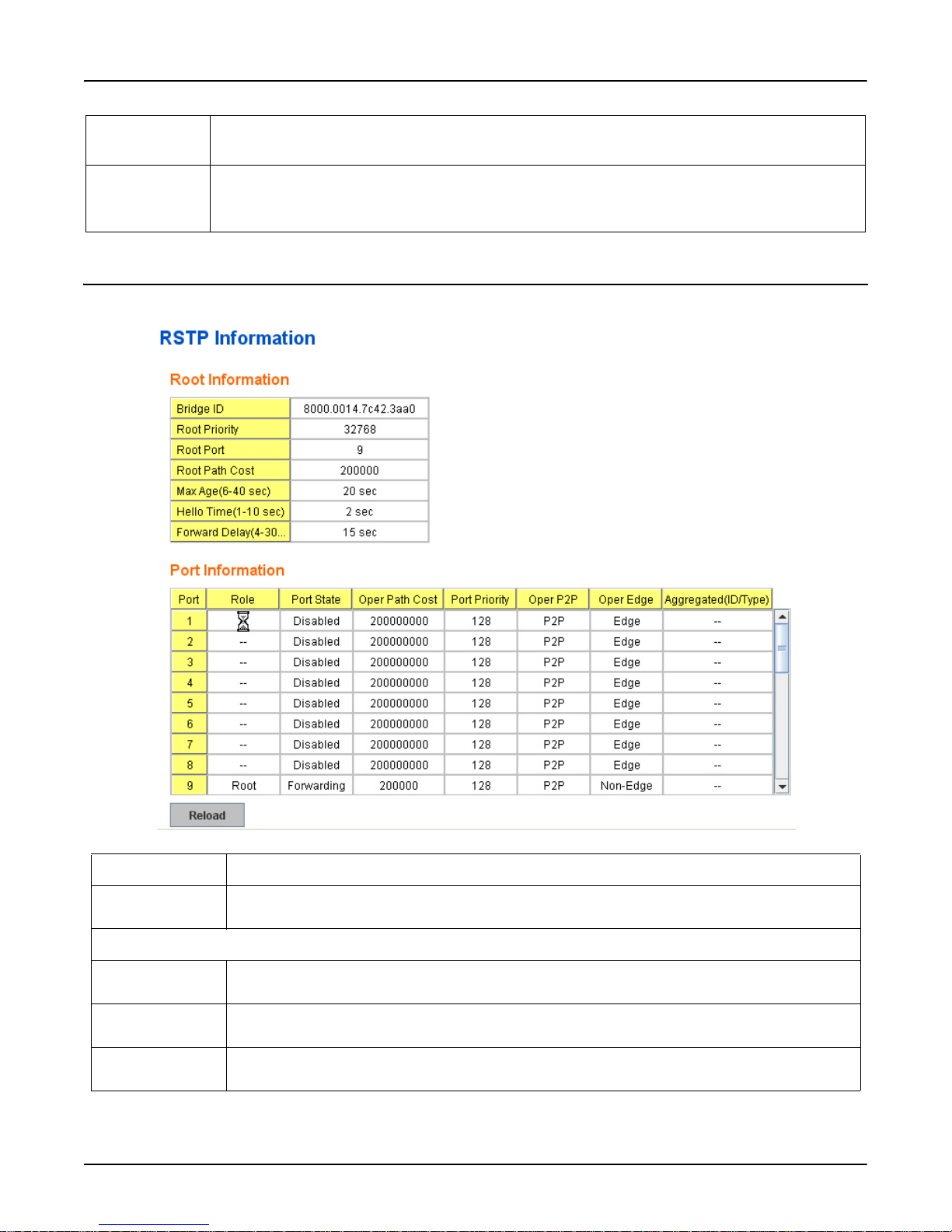
RSTP Information
Rapid Spanning
Tree Protocol
Description
Apply Click Apply to apply the settings.
Note: You must Save the settings (Page 137), if you want to maintain these settings if the RocketLinx
ES7528 is powered off.
RSTP Information
This page allows you to see the information of the root switch and port status.
RSTP Information Description
Root Information You can see root Bridge ID, Root Priority, Root Port, Root Path Cost and the Max Age, Hello Time
and Forward Delay of BPDU sent from the root switch.
Port Information
Port Role Descriptive information about the RSTP switch port role. Role Root, Designated, Alternate, Backup,
Disabled, Unknown.
Port State Descriptive information about the RSTP switch port state. State: Blocking, Listening, Learning, For-
warding, Disabled, Unknown.
Path Cost The cost of the path to the other bridge from this transmitting bridge at the specified port. Path cost
range is 1 through 200000000.
RSTP Information RocketLinx ES7528 Industrial Managed PoE Rack Mount User Guide: 2000509 Rev. A - 71
Page 72
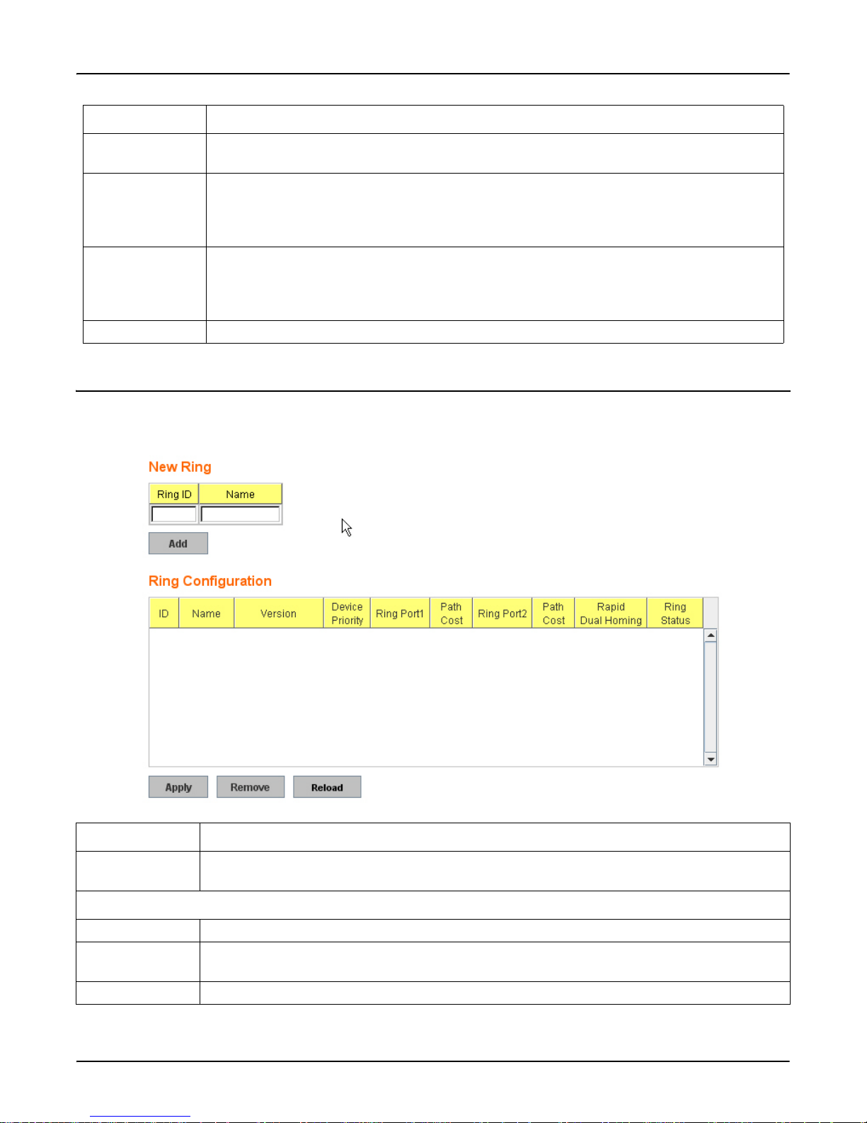
Redundant Ring
RSTP Information Description
Port Priority Decide which port should be blocked by priority in your LAN. Range is 0 through 240 in increments
of 16.
Oper P2P Some of the rapid state transactions that are possible within RSTP are dependent upon whether the
Port in question can be concerned to exactly one other Bridge (ie., it is served by a point-to-point
LAN segment), or can be connected to two or more Bridges (i.e., it is served by a shared medium
LAN segment).
Oper Edge Present in implementations that support the identification of edge ports. All ports directly connected
to end stations cannot create bridging loops in the network and can thus directly transition to forwarding, skipping the listening and learning stages. When the non-bridge device connects an admin
edge port, this port is in blocking state and turn to forwarding state in 4 seconds.
Reload Click to reload.
Redundant Ring
The most common industrial network redundancy is to form a ring or loop. Typically, the managed switches are connected in
series and the last switch is connected back to the first one. In such connection, you can implement Redundant Ring
technology.
Redundant Ring Description
New Ring To create a Redundant Ring enter the Ring ID, which has range from 0 to 31. If the name field is left
blank, the name of this ring is automatically named with the Ring ID
Ring Configuration
ID Once a Ring is created, this appears and can not be changed.
Name This field shows the name of the Ring. If it is not entered when creating, it is automatically named by
the rule RingID.
Version The version of Ring can be changed here, the choices are Rapid Super Ring or Super Ring.
72 - RocketLinx ES7528 Industrial Managed PoE Rack Mount User Guide: 2000509 Rev. A Redundant Ring
Page 73

Redundant Ring Description
Redundant Ring
Device Priority The switch with highest priority (highest value) is automatically selected as the Ring Master. When one
of the ring ports on this switch becomes a forwarding port and the other one becomes a blocking port.
If all of the switches have the same priority, the switch with the highest MAC address is selected as the
Ring Master.
Ring Port1 In a Rapid Super Ring environment, you should have two Ring Ports. Whether this switch is a Ring
Master or not. When configuring Rapid Super Rings, two ports should be selected to be Ring Ports. For
a Ring Master, one of the ring ports becomes the forwarding port and the other one becomes the
blocking port.
Path Cost Change the Path Cost of Ring Port1, if this switch is the Ring Master of a Ring, then it determines the
blocking port. The Port with higher Path Cost in the two ring ports becomes the blocking port, If the
Path Cost is the same, the port with larger port number becomes the blocking port.
Ring Port2 Assign another port for ring connection.
Path Cost Change the Path Cost of Ring Port2.
Rapid Dual Homing Rapid Dual Homing is an important feature of Rapid Super Ring redundancy technology. When you
want to connect multiple RSR or form redundant topology with other vendors, RDH allows you to
have a maximum of seven multiple links for redundancy without any problem.
In Rapid Dual Homing, you do not need to configure a specific port to connect to other protocol. The
Rapid Dual Homing selects the fastest link for the primary link and blocks all the other links to avoid a
loop. If the primary link failed, Rapid Dual Homing automatically forwards the secondary link for a
network redundant. If there are more connections, they are standby links and are recovered if both
primary and secondary links are broken.
Ring status To enable/disable the Ring. Please remember to enable the ring after you add it.
MultiRing This technology allows you to aggregate multiple rings within one switch. Create multiple ring IDs and
assign different ring Port1 and Port2 to each ring. Thus, the switch can have up to 14 rings in one
RocketLinx ES7528.
When implementing MultiRing, remember that the different rings can NOT use the same ring ID. The
other settings are the same as the above description. Technically, the maximum ring volume the
MultiRing support is up to 16 rings. Due to the power volume limitation, RocketLinx ES7528 supports
up to 14 rings.
Trunk Ring The MultiRing technology is part of the Redundant Ring technology which combines Redundant Ring
with the port trunking technology. After multiple ports are aggregated, so-called port trunking, the
Trunk ID can be one of the port IDs of the Redundant Ring technology. Configure the port trunking
first then configure the Trunk Ring in the managed switch.
Apply Click Apply to apply the settings.
Note: You must Save the settings (Page 137), if you want to maintain these settings if the RocketLinx
ES7528 is powered off.
Redundant Ring RocketLinx ES7528 Industrial Managed PoE Rack Mount User Guide: 2000509 Rev. A - 73
Page 74
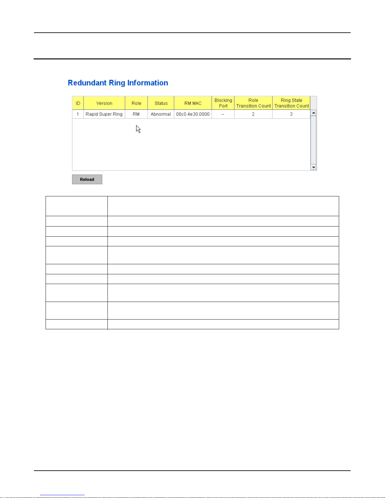
Redundant Ring Information
Redundant Ring Information
This page shows the RSR information.
Redundant Ring
Information
Description
ID The Ring ID.
Version Displays which version of this ring, this field could be Super Ring or Rapid Super Ring.
Role This Switch is RM (ring master) or nonRM (non-ring master).
Status If this field is Normal it means the redundancy is approved. If any one of the link in this
Ring is broken, then the status is Abnormal.
RM MAC The MAC address of Ring Master of this Ring. It helps to find the redundant path.
Blocking Port This field shows which is blocked port of RM.
Role Transition Count This shows how many times this switch has changed its Role from nonRM to RM or from
RM to nonRM.
Role state Transition
Count
This number shows how many times the Ring status has been transformed between
Normal and Abnormal state.
Reload Click to reload redundant ring information.
74 - RocketLinx ES7528 Industrial Managed PoE Rack Mount User Guide: 2000509 Rev. A Redundant Ring Information
Page 75

Command Lines for RSTP
Command Lines for RSTP
This table provides detailed information about the CLI command lines for RSTP.
Feature Command Line
RSTP
Enable Switch(config)# spanning-tree enable
Disable Switch(config)# spanning-tree disable
RSTP mode Switch(config)# spanning-tree mode rapid-stp
SpanningTree Mode change to be RST(802.1w) .
STP mode Switch(config)# spanning-tree mode stp
SpanningTree Mode change to be STP(802.1d) .
Priority Switch(config)# spanning-tree priority
<0-61440> valid range is 0 to 61440 in multiple of 4096
Switch(config)# spanning-tree priority 4096
Max Age Switch(config)# spanning-tree max-age
<6-40> Valid range is 6~40 seconds
Switch(config)# spanning-tree max-age 10
Hello Time Switch(config)# spanning-tree hello-time
<1-10> Valid range is 1~10 seconds
Switch(config)# spanning-tree hello-time 2
Forward Delay Switch(config)# spanning-tree forward-time
<4-30> Valid range is 4~30 seconds
Switch(config)# spanning-tree forward-time 15
Port Path Cost Switch(config-if)# spanning-tree cost
<1-200000000> 16-bit based value range from 1-65535, 32-bit based
value range
from 1-200,000,000
Switch(config-if)# spanning-tree cost 200000
Port Priority Switch(config-if)# spanning-tree port-priority
<0-240> Number from 0 to 240, in multiple of 16
Switch(config-if)# spanning-tree port-priority 128
Link Type - Auto Switch(config-if)# spanning-tree link-type auto
Link Type - P2P Switch(config-if)# spanning-tree link-type point-to-point
Command Lines for RSTP RocketLinx ES7528 Industrial Managed PoE Rack Mount User Guide: 2000509 Rev. A - 75
Page 76

Command Lines for RSTP
Feature Command Line
RSTP (cont.)
Link Type – Share Switch(config-if)# spanning-tree link-type shared
Edge Port Switch(config-if)# spanning-tree edge-port enable
Switch(config-if)# spanning-tree edge-port disable
RSTP Info
Active status Switch# show spanning-tree active
Rapid Spanning-Tree feature Enabled
Spanning-Tree BPDU transmission-limit 3
Root Address 00c0.4e01.0386 Priority 4096
Root Path Cost : 200000 Root Port : 7
Root Times : max-age 20 sec, hello-time 2 sec, forward-delay 15 sec
Bridge Address 00c0.4eff.0102 Priority 4096
Bridge Times : max-age 10 sec, hello-time 2 sec, forward-delay 15 sec
Aging time : 300
Port Role Port-State Cost Prio.Nbr Type
------- ---------- ------------ --------- ---------- ---------- fa6 Designated Forwarding 200000 128.6 Auto(RST)
fa7 Root Forwarding 200000 128.7 Shared(STP)
RSTP Summary Switch# show spanning-tree summary
Switch is in rapid-stp mode.
BPDU skewing detection disabled for the bridge.
Backbonefast disabled for bridge.
Summary of connected spanning tree ports :
#Port-State Summary
Blocking Listening Learning Forwarding Disabled
-------- --------- -------- ---------- ------- 0 0 0 2 8
#Port Link-Type Summary
AutoDetected PointToPoint SharedLink EdgePort
------------ ------------ ---------- ------- 9 0 1 9
76 - RocketLinx ES7528 Industrial Managed PoE Rack Mount User Guide: 2000509 Rev. A Command Lines for RSTP
Page 77

Command Lines for RSTP
Feature Command Line
RSTP Info (cont)
Port Info Switch# show spanning-tree port detail fa7 (Interface_ID)
Rapid Spanning-Tree feature Enabled
Port 128.6 as Disabled Role is in Disabled State
Port Path Cost 200000, Port Identifier 128.6
RSTP Port Admin Link-Type is Auto, Oper Link-Type is Point-to-Point
RSTP Port Admin Edge-Port is Enabled, Oper Edge-Port is Edge
Designated root has priority 32768, address 00c0.4e00.0112
Designated bridge has priority 32768, address 00c0.4e60.1aec
Designated Port ID is 128.6, Root Path Cost is 600000
Timers : message-age 0 sec, forward-delay 0 sec
Link Aggregation Group: N/A, Type: N/A, Aggregated with: N/A
BPDU: sent 43759 , received 4854
TCN : sent 0 , received 0
Forwarding-State Transmit count 12
Message-Age Expired count
Redundant Ring
Create or configure
a Ring
Switch(config)# redundant-ring 1
Ring 1 created
Switch(config-redundant-ring)#
Note: 1 is the target Ring ID which is going to be created or configured.
Super Ring
Ve rs i on
Switch(config-redundant-ring)# version
default set default to Redundant ring
rapid-super-ring rapid super ring
super-ring super ring
Switch(config-redundant-ring)# version rapid-super-ring
Priority Switch(config-redundant-ring)# priority
<0-255> valid range is 0 to 255
default set default
Switch(config-redundant-ring)# super-ring priority 100
Ring Port Switch(config-redundant-ring)# port
IFLIST Interface list, ex: fa1,fa3-5,gi25-28
cost path cost
Switch(config-redundant-ring)# port fa1,fa2
Command Lines for RSTP RocketLinx ES7528 Industrial Managed PoE Rack Mount User Guide: 2000509 Rev. A - 77
Page 78

Command Lines for RSTP
Feature Command Line
Redundant Ring (cont.)
Ring Port Cost Switch(config-redundant-ring)# port cost
<0-255> valid range is 0 or 255
default set default (128)valid range is 0 or 255
Switch(config-redundant-ring)# port cost 100
<0-255> valid range is 0 or 255
default set default (128)valid range is 0 or 255
Switch(config-super-ring-plus)# port cost 100 200
Set path cost success.
Rapid Dual
Switch(config-redundant-ring)# rapid-dual-homing enable
Homing
Switch(config-redundant-ring)# rapid-dual-homing disable
Switch(config-redundant-ring)# rapid-dual-homing port
IFLIST Interface name, ex: fastethernet1 or gi25
auto-detect Uplink auto detection
IFNAME Interface name, ex: fastethernet1 or gi25
Switch(config-redundant-ring)# rapid-dual-homing port fa3,fa5-6
set Rapid Dual Homing port success.
Note: Auto-detect is recommended for dual Homing.
Ring Info
Ring Info Switch# show redundant-ring [Ring ID]
[Ring1] Ring1
Current Status : Disabled
Role : Disabled
Ring Status : Abnormal
Ring Manager : 0000.0000.0000
Blocking Port : N/A
Giga Copper : N/A
Configuration :
Version : Rapid Super Ring
Priority : 128
Ring Port : fa1, fa2
Path Cost : 100, 200
Dual-Homing II : Disabled
Statistics :
Watchdog sent 0, received 0, missed 0
Link Up sent 0, received 0
Link Down sent 0, received 0
Role Transition count 0
Ring State Transition count 1
Ring ID is optional. If the ring ID is typed, this command only
displays the information of the target Ring.
78 - RocketLinx ES7528 Industrial Managed PoE Rack Mount User Guide: 2000509 Rev. A Command Lines for RSTP
Page 79
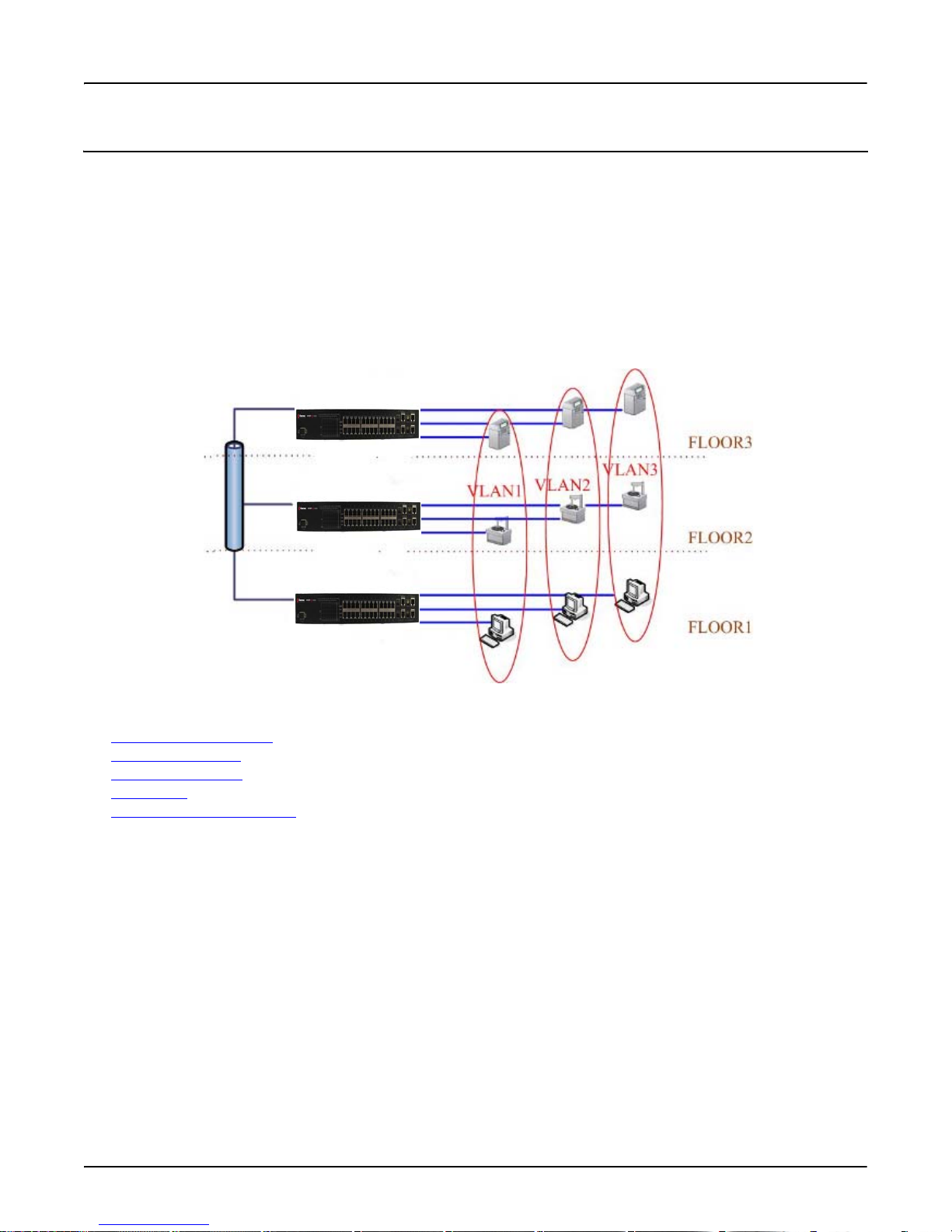
VLAN
VLAN
A Virtual LAN (VLAN) is a logical grouping of nodes for the purpose of limiting a broadcast domain to specific members of a
group without physically grouping the members. The VLAN allows you to isolate network traffic so that only members of the
VLAN could receive traffic from the same VLAN members. Basically, creating a VLAN from a switch is the logical
equivalent of physically reconnecting a group of network devices to another layer 2 switch, without actually disconnecting
these devices from their original switches.
The RocketLinx ES7528 supports 802.1Q VLAN, which is also known as Tag-Based VLAN. This Tag-Based VLAN allows a
VLAN to be created across different switches. IEEE 802.1Q tag-based VLAN makes use of VLAN control information stored
in a VLAN header attached to IEEE 802.3 packet frames. This tag contains a VLAN Identifier (VID) that indicates which
VLAN a frame belongs to. Since each switch only has to check a frame’s tag, without the need to dissect the contents of the
frame, this also saves a lot of computing resources within the switch.
The following figure displays an 802.1Q VLAN.
VLAN Configuration group enables you to Add/Remove a VLAN, configure port Ingress/Egress parameters, and view VLAN
table. The following commands are included in this group:
• VLAN Port Configuration
• VLAN Configuration
• GVRP Configuration
• VLAN Tabl e
• CLI Commands for the VLAN
on Page 84
on Page 80
on Page 81
on Page 83
on Page 85
VLAN RocketLinx ES7528 Industrial Managed PoE Rack Mount User Guide: 2000509 Rev. A - 79
Page 80
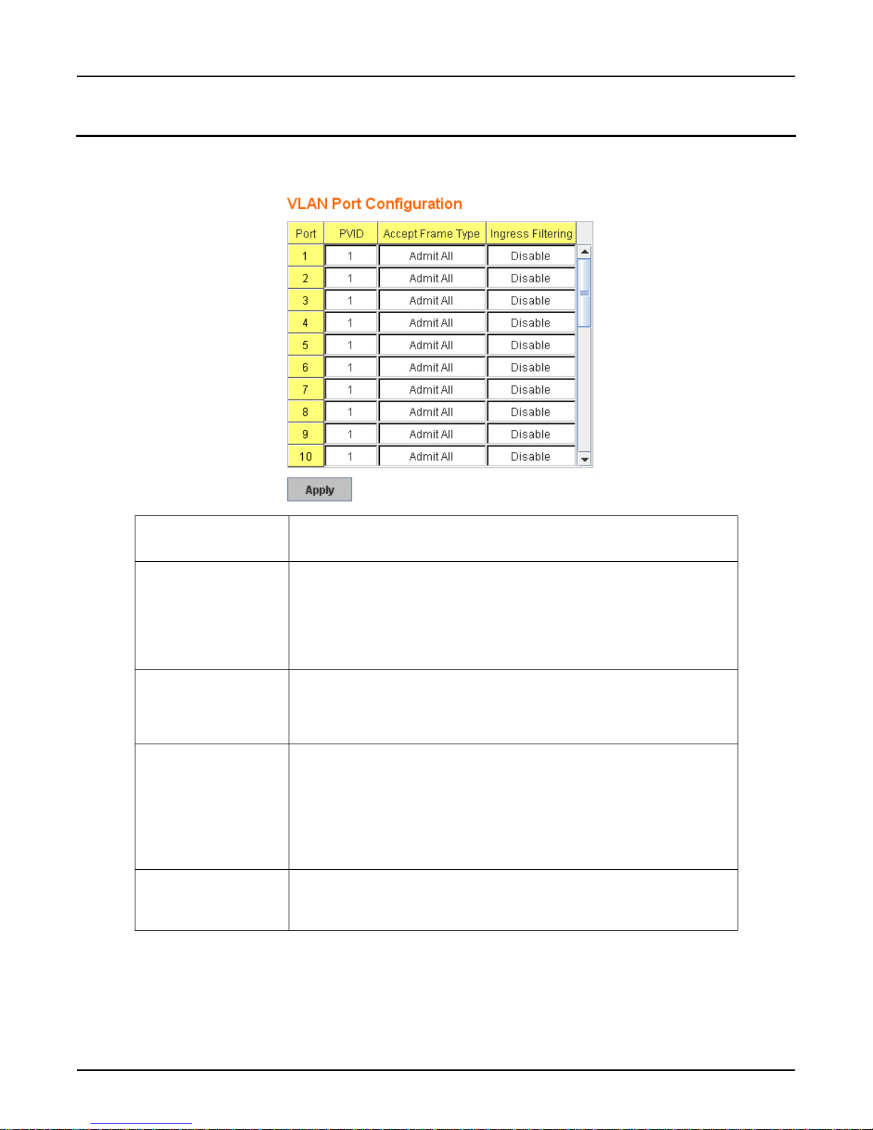
VLAN Port Configuration
VLAN Port Configuration
VLAN Port Configuration allows you to set up VLAN port parameters to a specific port. These parameters include PVID,
Accept Frame Type and Ingress Filtering.
VLAN Port
Configuration
Description
PVID Enter the port VLAN ID (PVID). The PVID allows the switches to identify
which port belongs to which VLAN. To keep things simple, it is
recommended that PVID is equivalent to VLAN IDs. The values of PVIDs
are from 0 to 4,095, but 0 and 4,095 are reserved. 1 is the default value. 2 to
4,094 are valid and available in this column. Type the PVID you want to
configure.
Accept Frame Type This column defines the accepted frame type of the port. There are two
modes you can select, Admit All and Tag Only. Admit All mode means that
the port can accept both tagged and untagged packets. Tag Only mode means
that the port can only accept tagged packets.
Ingress Filtering Ingress filtering instructs the VLAN engine to filter out undesired traffic on a
port. When Ingress Filtering is enabled, the port checks whether the incoming
frames belong to the VLAN they claimed or not. The port then determines if
the frames can be processed or not. For example, if a tagged frame from
Engineer VLAN is received, and Ingress Filtering is enabled, the switch
determines if the port is on the Engineer VLAN’s Egress list. If it is, the
frame can be processed. If it is not, the frame is dropped.
Apply Click Apply to apply the settings.
Note: You must Save the settings (Page 137), if you want to maintain these
settings if the RocketLinx ES7528 is powered off.
80 - RocketLinx ES7528 Industrial Managed PoE Rack Mount User Guide: 2000509 Rev. A VLAN Port Configuration
Page 81
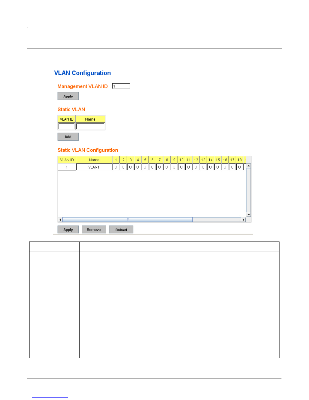
VLAN Configuration
VLAN Configuration
Use this page to assign the Management VLAN, create the static VLAN, and assign the Egress rule for the member ports of the
VLAN.
VLAN Configuration Description
Management VLAN IDThe RocketLinx ES7528 supports management VLAN. The management VLAN ID is the VLAN
ID of the CPU interface so that only member ports of the management VLAN can ping and access
the switch. The default management VLAN ID is 1.
Click Apply after you enter the VLAN ID.
Static VLAN You can assign a VLAN ID and VLAN Name for new VLAN.
• VLAN ID: This is used by the switch to identify different VLANs. A valid VLAN ID is
between 1 and 4,094, 1 is the default VLAN.
• VLAN Name: This is a reference for the network administrator to identify different VLANs.
The VLAN name may up to 12 characters in length. If you do not provide a VLAN name, the
system automatically assigns a VLAN name for this VLAN. The rule is VLAN (VLAN ID).
Click Add to create a new VLAN. The new VLAN displays in the Static VLAN Configuration
table. After creating the VLAN, the status of the VLAN remains Unused, until you add ports to
the VLAN.
Note: Before changing the management VLAN ID by web or Telnet, remember that the port
attached by the administrator should be the member port of the management VLAN;
otherwise the administrator cannot access the switch through the network. The
RocketLinx ES7528 supports a maximum of 64 VLANs.
VLAN Configuration RocketLinx ES7528 Industrial Managed PoE Rack Mount User Guide: 2000509 Rev. A - 81
Page 82
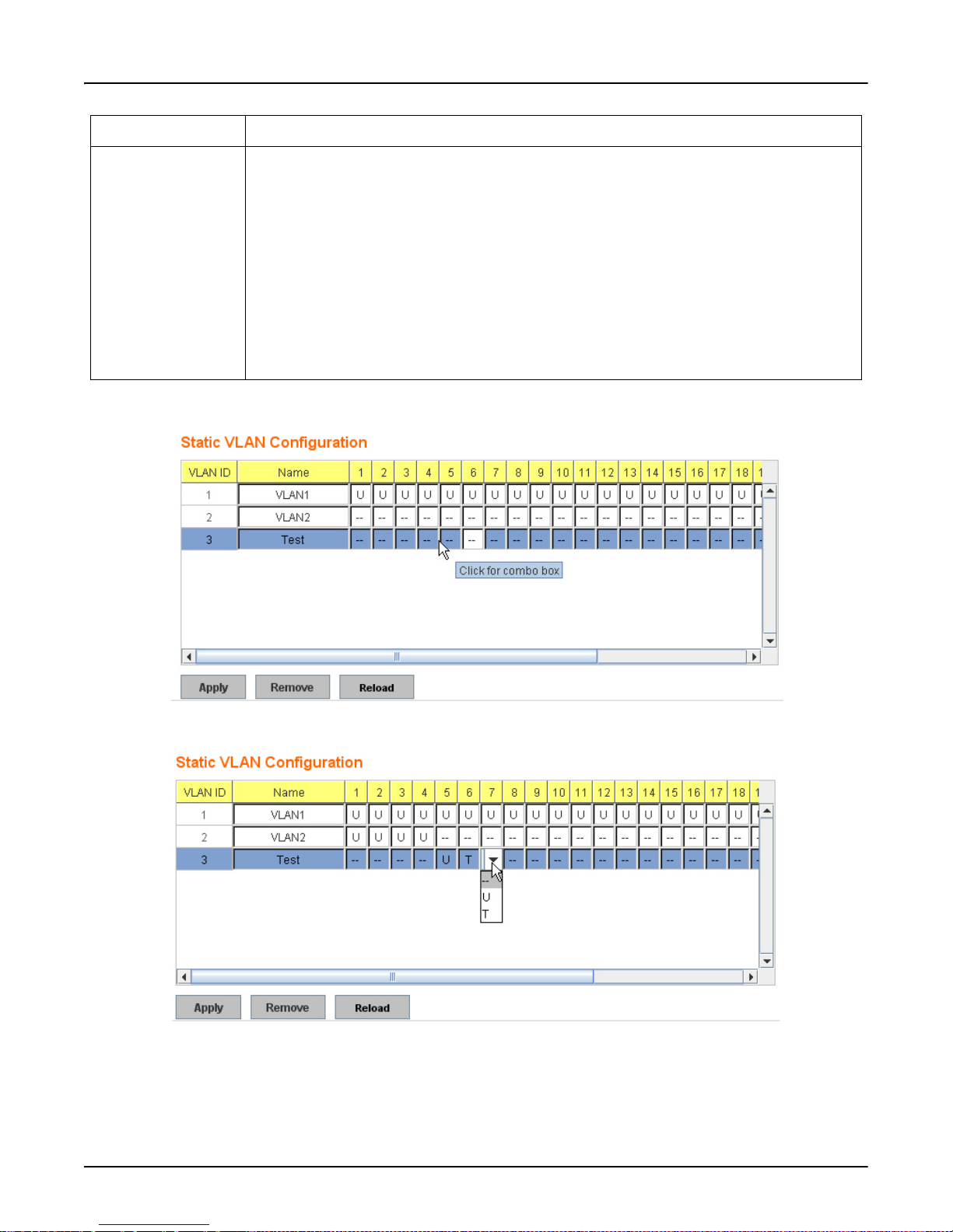
VLAN Configuration
VLAN Configuration Description
Static VLAN
Configuration
• VLAN ID: The VLAN identifier for this VLAN.
• Name: The name of the VLAN.
• 1 - 28: The corresponding port number on the VLAN.
• -- Not available
• U Untag, indicates that egress/outgoing frames are not VLAN tagged.
• T Tag, indicates that egress/outgoing frames are to be VLAN tagged.
•Click Apply to apply the settings.
Note: You must Save the settings (Page 137), if you want to maintain these settings if the
RocketLinx ES7528 is powered off.
•Click Remove to remove the selected static VLAN.
•Click Reload to reload static VLAN configuration.
The following figure shows a static VLAN configuration table. The new VLAN 3 was created and the VLAN name is test.
Egress rules of the ports are not configured.
This figure displays how to configure the Egress rule of the ports.
Use the following steps to configure Egress rules: Select the VLAN ID. Entry of the selected VLAN turns to light blue. Assign
Egress rule of the ports to U or T. Press Apply to apply the setting. If you want to remove one VLAN, select the VLAN entry
and then click the Remove button.
82 - RocketLinx ES7528 Industrial Managed PoE Rack Mount User Guide: 2000509 Rev. A VLAN Configuration
Page 83
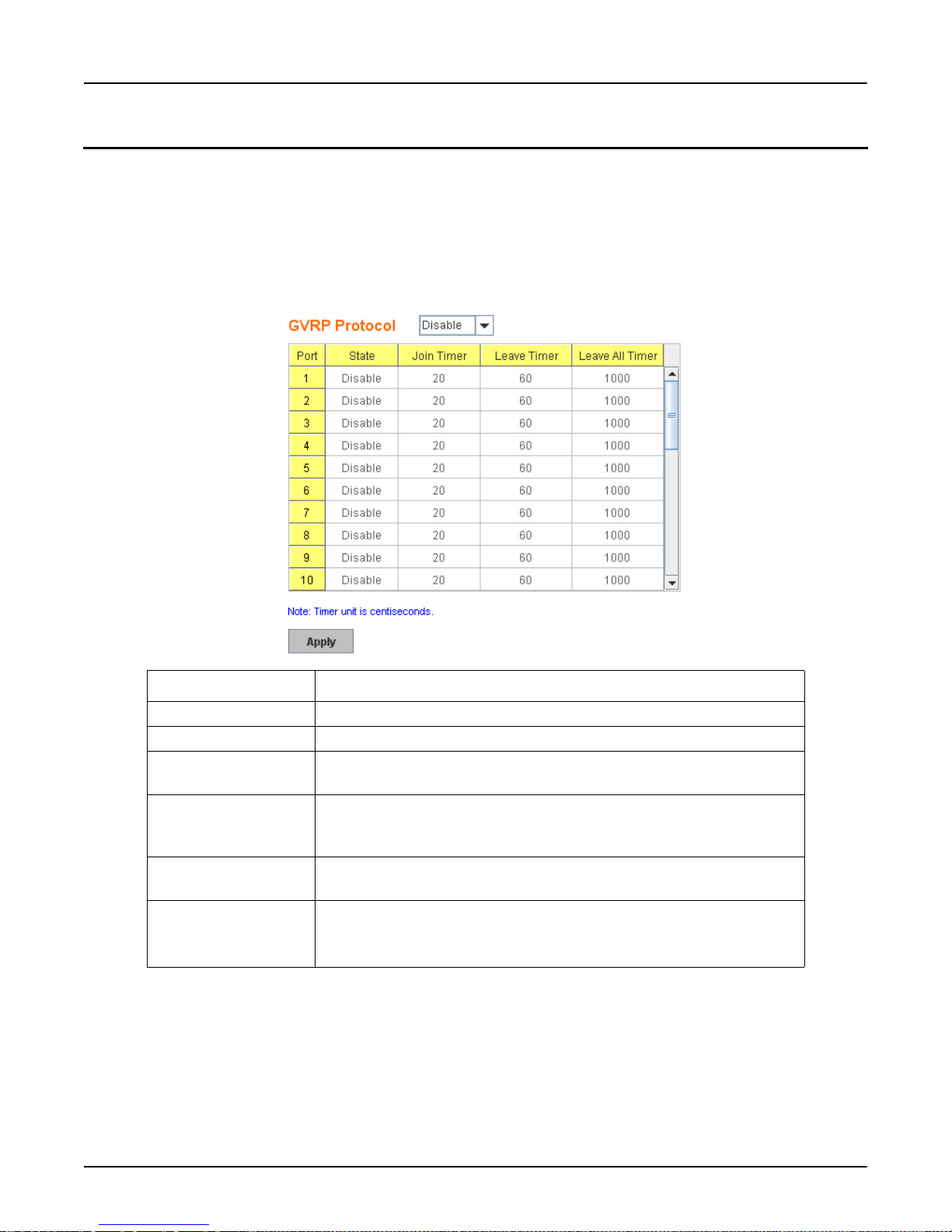
GVRP Configuration
GVRP Configuration
GVRP allows you to set-up VLANs automatically rather than manual configuration on every port of every switch in the
network. GVRP conforms to the IEEE 802.1Q specification. This defines a method of tagging frames with VLAN
configuration data that allows network devices to dynamically exchange VLAN configuration information with other devices.
GARP (Generic Attribute Registration Protocol), a protocol that defines procedures by which end stations and switches in a
local area network (LAN) can register and de-register attributes, such as identifiers or addresses, with each other. Every end
station and switch thus has a current record of all the other end stations and switches that can be reached. GVRP, like GARP,
eliminates unnecessary network traffic by preventing attempts to transmit information to unregistered users. In addition, it is
necessary to manually configure only one switch and all the other switches will be configured accordingly.
GVRP Configuration Description
GVRP Protocol Allows you to Enable/Disable GVRP globally.
State After enabling GVRP globally, you can still Enable/Disable GVRP by port.
Join Timer Controls the interval of sending the GVRP Join BPDU. An instance of this
timer is required on a per-Port, per-GARP Participant basis.
Leave Timer Controls the time to release the GVRP reservation after having received the
GVRP Leave BPDU. An instance of the timer is required for each state
machine that is in the LV state.
Leave All Timer Controls the period to initiate the garbage collection of registered VLAN.
The timer is required on a per-Port, per-GARP Participant basis.
Apply Click Apply to apply the settings.
Note: You must Save the settings (Page 137), if you want to maintain these
settings if the RocketLinx ES7528 is powered off.
GVRP Configuration RocketLinx ES7528 Industrial Managed PoE Rack Mount User Guide: 2000509 Rev. A - 83
Page 84
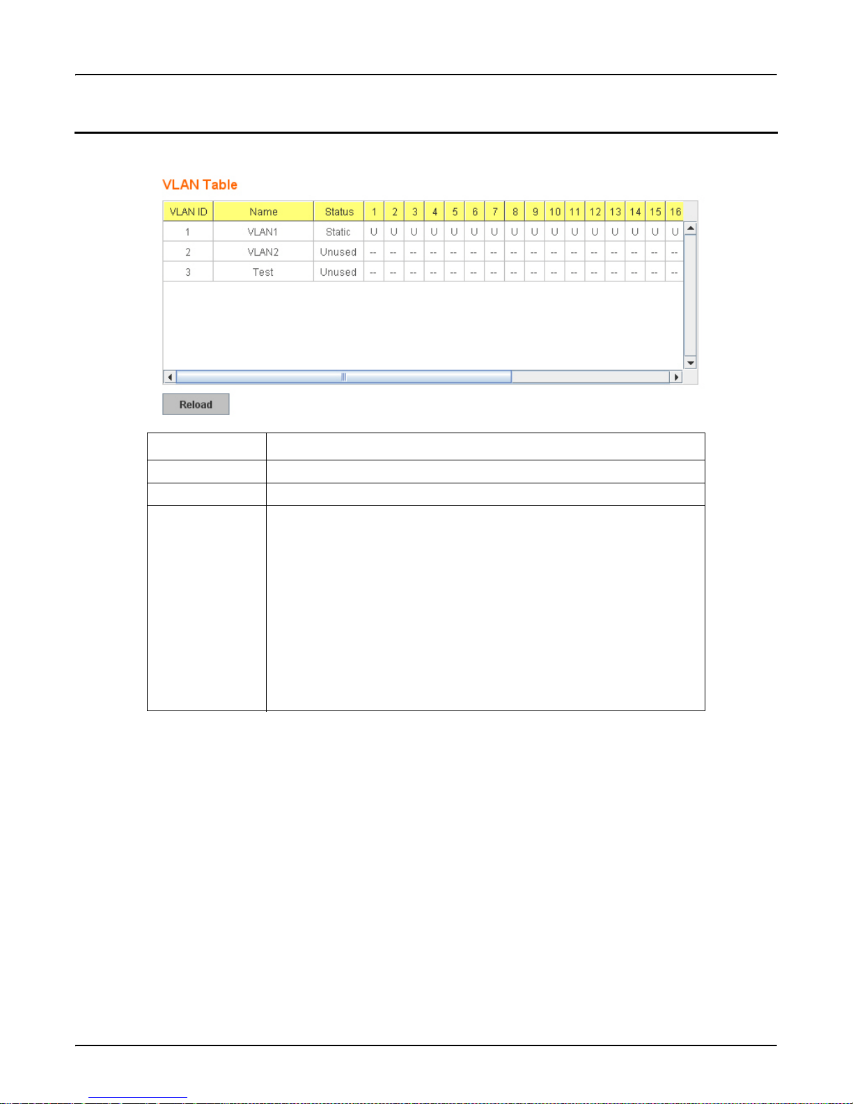
VLAN Table
VLAN Table
This table displays the current settings of your VLAN table, including VLAN ID, Name, Status, and Egress rule of the ports.
VLAN Table Description
VLAN ID ID of the VLAN.
Name Name of the VLAN.
Status Static shows this is a manually configured static VLAN. Unused means this
VLAN is created by UI/CLI and has no member ports. This VLAN is not
workable yet. Dynamic means this VLAN was learnt by GVRP.
• -- No VLAN setting.
• T A Trunk Link is a LAN segment used for multiplexing VLANs
between VLAN bridges. All the devices that connect to a Trunk Link
must be 802.1Q VLAN-aware, which sends and receives frames with
802.1Q tags.
• U An Access Link is a LAN segment used to multiplex one or more
802.1Q VLAN-unaware devices into a Port of a VLAN Bridge. Devices
that are connected to an Access Link sends and receives frames without
802.1Q tagging, which is the identification of the VLAN it belongs to.
After creating the VLAN, the status of this VLAN remains in Unused status until you add ports to the VLAN.
84 - RocketLinx ES7528 Industrial Managed PoE Rack Mount User Guide: 2000509 Rev. A VLAN Table
Page 85

CLI Commands for the VLAN
CLI Commands for the VLAN
The following table provides detailed information about command lines for VLAN port configuration, VLAN configuration,
and VLAN table display.
Feature Command Line
VLAN Port Configuration
VLAN Port PVID Switch(config-if)# switchport trunk native vlan 2
Set port default vlan id to 2 success
Port Accept Frame
Type
Ingress Filtering (for
Fast Ethernet Port 1)
Egress rule – Untagged
(for VLAN 2)
Egress rule – Tagged
(for VLAN 2)
Display – Port Ingress
Rule (PVID, Ingress
Filtering, Acceptable
Frame Type)
Switch(config)# inter fa1
Switch(config-if)# acceptable frame type all
any kind of frame type is accepted!
Switch(config-if)# acceptable frame type vlantaggedonly
only vlan-tag frame is accepted!
Switch(config)# interface fa1
Switch(config-if)# ingress filtering enable
ingress filtering enable
Switch(config-if)# ingress filtering disable
ingress filtering disable
Switch(config-if)# switchport access vlan 2
switchport access vlan - success
Switch(config-if)# switchport trunk allowed vlan add 2
Switch# show interface fa1
Interface fastethernet1
Administrative Status : Enable
Operating Status : Not Connected
Duplex : Auto
Speed : Auto
Flow Control :off
Default Port VLAN ID: 2
Ingress Filtering : Disabled
Acceptable Frame Type : All
Port Security : Disabled
Auto Negotiation : Enable
Loopback Mode : None
STP Status: disabled
Default CoS Value for untagged packets is 0.
Mdix mode is Auto.
Medium mode is Copper.
CLI Commands for the VLAN RocketLinx ES7528 Industrial Managed PoE Rack Mount User Guide: 2000509 Rev. A - 85
Page 86

CLI Commands for the VLAN
VLAN Port Configuration (continued)
Display – Port Egress
Rule (Egress rule, IP
address, status)
Switch# show running-config
……
!
interface fastethernet1
switchport access vlan 1
switchport access vlan 3
switchport trunk native vlan 2
…….
interface vlan1
ip address 192.168.250.8/24
no shutdown
VLAN Configuration
Create VLAN (2) Switch(config)# vlan 2
vlan 2 success
Switch(config)# interface vlan 2
Switch(config-if)#
Note: In the CLI configura tio n, you should first crea te a VLAN interface. Th en you can start to
add/remove ports. The default status of the created VLAN is unused until you add member
ports to it.
Remove VLAN Switch(config)# no vlan 2
no vlan success
Note: You can only remove the VLAN when the VLAN is in unused mode.
VLAN Name Switch(config)# vlan 2
vlan 2 has exists
Switch(config-vlan)# name v2
Switch(config-vlan)# no name
Note: Use no name to change the name to default name, VLAN VID.
VLAN description Switch(config)# interface vlan 2
Switch(config-if)#
Switch(config-if)# description this is the VLAN 2
Switch(config-if)# no description ->Delete the description.
IP address of the
VLAN
Switch(config)# interface vlan 2
Switch(config-if)#
Switch(config-if)# ip address 192.168.250.18/24
Switch(config-if)# no ip address 192.168.250.8/24 ->Delete the IP
address
Create multiple
Switch(config)# interface vlan 5-10
VLANs (VLAN 5-10)
Shut down VLAN Switch(config)# interface vlan 2
Switch(config-if)# shutdown
Switch(config-if)# no shutdown ->Turn on the VLAN
86 - RocketLinx ES7528 Industrial Managed PoE Rack Mount User Guide: 2000509 Rev. A CLI Commands for the VLAN
Page 87

VLAN Configuration (continued)
Display – VLAN table Switch# sh vlan
VLAN Name Status Trunk Ports Access Ports
---- ---- ------ ------------ -------------------------1 VLAN1 Static - fa1-7,gi25-28
2 VLAN2 Unused - 3 test Static fa4-7,gi25-28 fa1-3,fa7,gi25-28
Display – VLAN
interface information
Switch# show interface vlan1
interface vlan1 is up, line protocol detection is disabled
index 14 metric 1 mtu 1500 <UP,BROADCAST,RUNNING,MULTICAST>
HWaddr: 00:c0:4e:ff:01:b0
inet 192.168.250.100/24 broadcast 192.168.250.255
input packets 639, bytes 38248, dropped 0, multicast packets 0
input errors 0, length 0, overrun 0, CRC 0, frame 0, fifo 0,
missed 0
output packets 959, bytes 829280, dropped 0
output errors 0, aborted 0, carrier 0, fifo 0, heartbeat 0,
window 0
collisions 0
CLI Commands for the VLAN
GVRP Configuration
GVRP enable/disable Switch(config)# gvrp mode
disable Disable GVRP feature globally on the switch
enable Enable GVRP feature globally on the switch
Switch(config)# gvrp mode enable
Gvrp is enabled on the switch!
Configure GVRP timer
Switch(config)# inter fa1
Switch(config-if)# garp timer
<10-10000>
Join timer /Leave
timer/ LeaveAll timer
Switch(config-if)# garp timer 20 60 1000
Note: The un it of this timer is centiseconds.
Management VLAN
Management VLAN Switch(config)# int vlan 1 (Go to management VLAN)
Switch(config-if)# no shutdown
Display Switch# show running-config
….
!
interface vlan1
ip address 192.168.250.17/24
ip igmp
no shutdown
!
….
CLI Commands for the VLAN RocketLinx ES7528 Industrial Managed PoE Rack Mount User Guide: 2000509 Rev. A - 87
Page 88

Traffic Prioritization
Traffic Prioritization
Quality of Service (QoS) provides a traffic prioritization mechanism which allows you to deliver better service to certain
flows. QoS can also help to alleviate congestion problems and ensure high-priority traffic is delivered first. This section allows
you to configure Traffic Prioritization settings for each port with regard to setting priorities.
RocketLinx ES7528 QOS supports four physical queues, weighted fair queuing (WRR) and Strict Priority scheme, that follows
the 802.1p COS tag and IPv4 TOS/DiffServ information to prioritize the traffic of your industrial network.
The following commands are included in this group:
• QoS Setting
• CoS-Queue Mapping
• DSCP-Queue Mapping
• CLI Commands of the Traffic Prioritization on Page 92
88 - RocketLinx ES7528 Industrial Managed PoE Rack Mount User Guide: 2000509 Rev. A Traffic Prioritization
Page 89
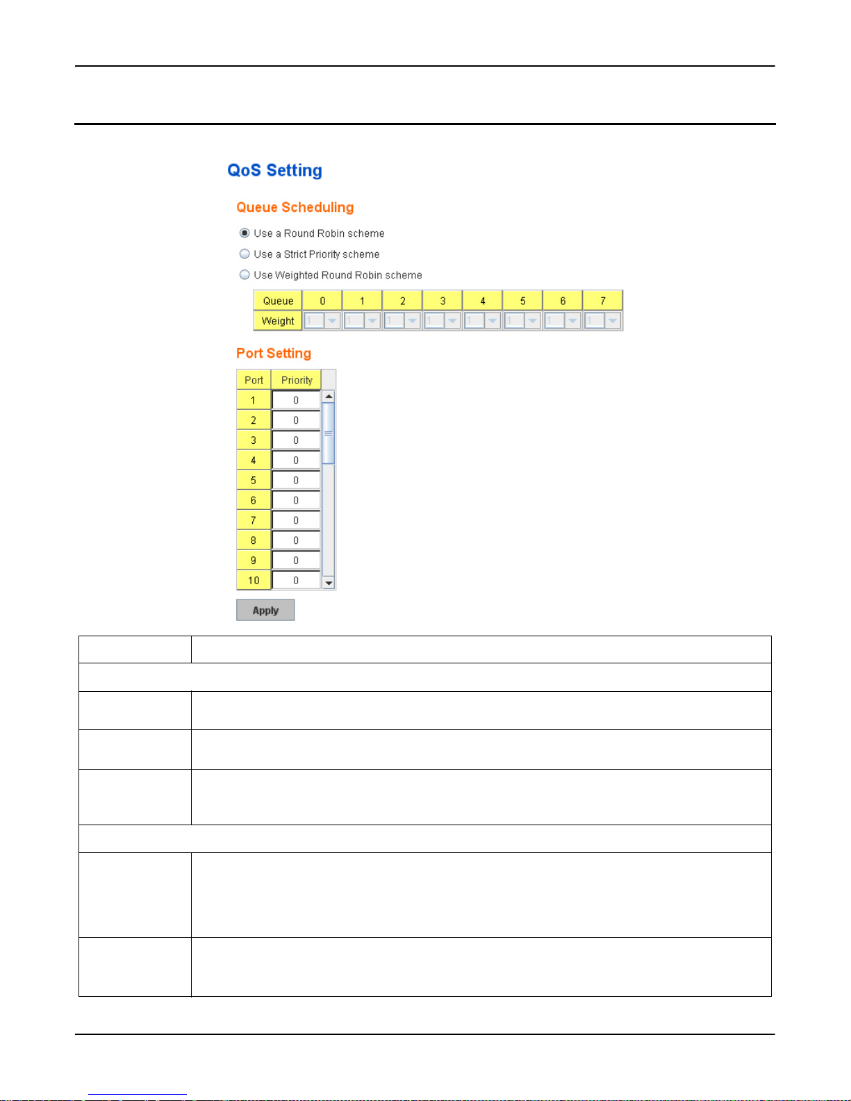
QoS Setting
Use this subsection to set up QoS settings for the RocketLinx ES7528.
QoS Setting
QoS Setting Description
Queue Scheduling
Use a Round
Robin scheme
Use a strict
priority scheme
Use Weighted
Round Robin
scheme
The Round Robin scheme means all the priority has the same privilege, the traffic is forward cyclic
from highest to lowest.
Packets with higher priority in the queue are always processed first, except that there is no packet with
higher priority.
This scheme allows you to assign new weight ratio for each class. The 10 is the highest ratio. The ratio
of each class is:
Wx / W0 + W1 + W2 + W3 + W4 + W5 + W6 + W7 (Total volume of Queue 0-7)
Port Setting
Priority Indicates the default port priority value for untagged or priority-tagged frames. When the RocketLinx
ES7528 receives the frames, the RocketLinx ES7528 attaches the value to the CoS field of the
incoming VLAN-tagged packets. You can enable 0,1,2,3,4,5,6 or 7 to the port.
Default priority type is COS. The system provides default COS-Queue table to which you can refer for
the next command.
Apply Click Apply to apply the settings.
Note: You must Save the settings (Page 137), if you want to maintain these settings if the RocketLinx
ES7528 is powered off.
QoS Setting RocketLinx ES7528 Industrial Managed PoE Rack Mount User Guide: 2000509 Rev. A - 89
Page 90
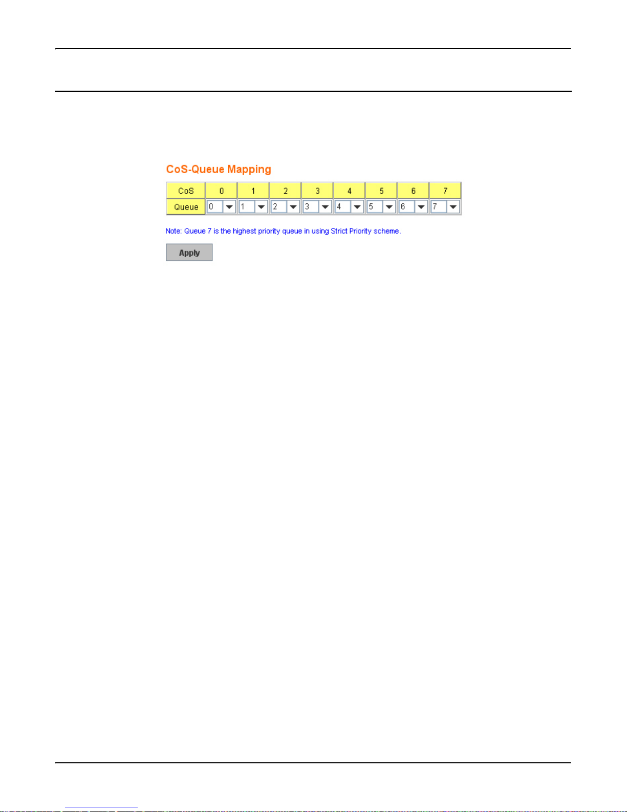
CoS-Queue Mapping
CoS-Queue Mapping
Use this page to change the CoS values into a Physical Queue mapping table. Since the switch fabric of the RocketLinx
ES7528 only supports eight queues, Lowest, Low, Middle and High. You should therefore assign how to map CoS value to the
level of the physical queue.
Class of service (CoS) is a 3 bit field within a layer two Ethernet frame header defined by IEEE 802.1p when using 802.1Q
tagging. The field specifies a priority value of between 0 and 7 inclusive that can be used by Quality of Service (QoS)
disciplines to differentiate traffic.
While CoS operates only on Ethernet at the data link layer, other QoS mechanisms (such as DiffServ) operate at the network
layer and higher. Others operate on other physical layers. Although 802.1Q tagging must be enabled to communicate priority
information from switch to switch, some switches use CoS to internally classify traffic for QoS purposes.
Differentiated Services (DiffServ) is a model where traffic is treated by intermediate systems with relative priorities based on
the type of services (ToS) field. Defined in RFC2474 and RFC2475, the DiffServ standard supersedes the original specification
for defining packet priority described in RFC791. DiffServ increases the number of definable priority levels by reallocating
bits of an IP packet for priority marking. The DiffServ architecture defines the DiffServ field, which supersedes the ToS field
in IPv4 to make per-hop behavior (PHB) decisions about packet classification and traffic conditioning functions, such as;
metering, marking, shaping, and policing.
After configuration, press Apply to enable the settings.
Note: You must Save the settings (Page 137), if you want to maintain these settings if the RocketLinx ES7528 is powered off.
90 - RocketLinx ES7528 Industrial Managed PoE Rack Mount User Guide: 2000509 Rev. A CoS-Queue Mapping
Page 91
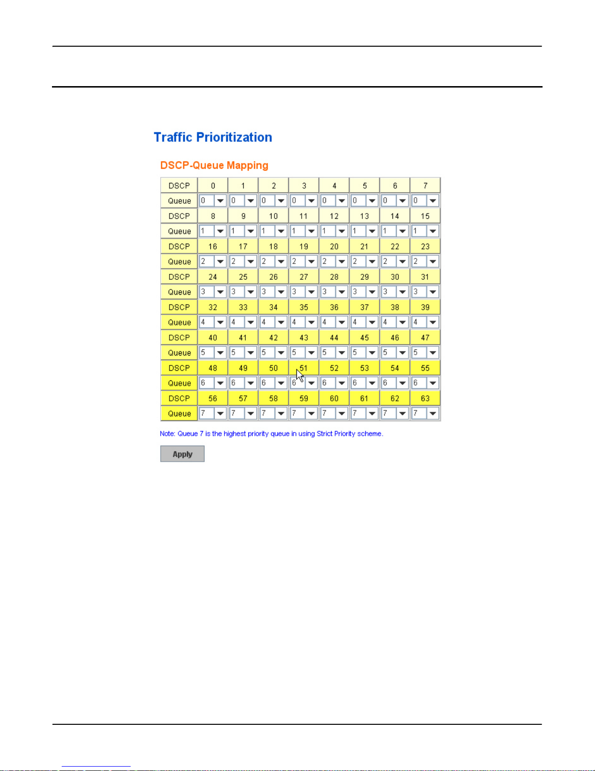
DSCP-Queue Mapping
DSCP-Queue Mapping
Use this page to change DSCP values to Physical Queue mapping table. Since the switch fabric of the RocketLinx ES7528
only supports eight queues. You can change the mapping table to follow the upper layer 3 switch or routers’ DSCP setting.
After configuration, press Apply to enable the settings.
Note: You must Save the settings (Page 137), if you want to maintain these settings if the RocketLinx ES7528 is powered off.
DSCP-Queue Mapping RocketLinx ES7528 Industrial Managed PoE Rack Mount User Guide: 2000509 Rev. A - 91
Page 92

CLI Commands of the Traffic Prioritization
CLI Commands of the Traffic Prioritization
This table provides detailed information about command lines for traffic prioritization configuration
Feature Command Line
QoS Setting
Queue Scheduling –
Round Robin
Switch(config)# qos queue-sched
rr Round Robin
sp Strict Priority
wrr Weighted Round Robin
Switch(config)# qos queue-sched rr
The queue scheduling scheme is setting to Round Robin.
Queue Scheduling –
Strict Priority
Queue Scheduling WRR
Switch(config)# qos queue-sched sp
The queue scheduling scheme is setting to Strict Priority.
Switch(config)# qos queue-sched wrr 1 1 1 1 1 1 1 1
The queue scheduling scheme is setting to Weighted Round Robin.
Port Setting – Priority Switch(config)# interface fa1
Switch(config-if)# qos priority
DEFAULT-PRIORITY Assign an priority (7 highest)
Switch(config-if)# qos priority 7
The default port priority value is set 7 ok.
Note: When change the port setting, you should Select the specific port first. Ex: fa1 means Fast
Ethernet Port 1.
Display – Queue
Scheduling
Switch# show qos queue-sched
QoS queue scheduling scheme: Weighted Round Robin (Use an 8,4,2,1 weight)
Display – Port Setting Switch# show qos port-priority
Port Default Priority :
Port Priority
-----+--- 1 0
2 0
3 0
4 0
5 0
6 0
7 0
8 0
9 0
10 0
…
26 0
27 0
28 0
92 - RocketLinx ES7528 Industrial Managed PoE Rack Mount User Guide: 2000509 Rev. A CLI Commands of the Traffic Prioritization
Page 93

CoS-Queue Mapping
Format Switch(config)# qos cos-map
PRIORITY Assign an priority (7 highest)
Switch(config)# qos cos-map 1
QUEUE Assign an queue (0-7)
Format: qos cos-map priority_value queue_value.
Map CoS 0 to Queue 0 Switch(config)# qos cos-map 0 0
The CoS to queue mapping is set ok.
Map CoS 1 to Queue 1 Switch(config)# qos cos-map 1 1
The CoS to queue mapping is set ok.
Map CoS 2 to Queue 2 Switch(config)# qos cos-map 2 2
The CoS to queue mapping is set ok.
Map CoS 3 to Queue 3 Switch(config)# qos cos-map 3 3
The CoS to queue mapping is set ok.
Map CoS 4 to Queue 4 Switch(config)# qos cos-map 4 4
The CoS to queue mapping is set ok.
Map CoS 5 to Queue 5 Switch(config)# qos cos-map 5 5
The CoS to queue mapping is set ok.
Map CoS 6 to Queue 6 Switch(config)# qos cos-map 6 6
The CoS to queue mapping is set ok.
Map CoS 7 to Queue 7 Switch(config)# qos cos-map 7 7
The CoS to queue mapping is set ok.
Display – CoS-Queue
mapping
Switch# sh qos cos-map
CoS to Queue Mapping :
CoS Queue
---- + ----- 0 0
1 1
2 2
3 3
4 4
5 5
6 6
7 7
CLI Commands of the Traffic Prioritization
DSCP-Queue Mapping
Format Switch(config)# qos dscp-map
PRIORITY Assign an priority (63 highest)
Switch(config)# qos dscp-map 0
QUEUE Assign an queue (0-7)
Format: qos dscp-map priority_value queue_value.
Map DSCP 0 to Queue 1Switch(config)# qos dscp-map 0 1
The TOS/DSCP to queue mapping is set ok.
CLI Commands of the Traffic Prioritization RocketLinx ES7528 Industrial Managed PoE Rack Mount User Guide: 2000509 Rev. A - 93
Page 94

CLI Commands of the Traffic Prioritization
DSCP-Queue Mapping (cont.)
Display – DSCOQueue mapping
Switch# show qos dscp-map
DSCP to Queue Mapping : (dscp = d1 d2)
d2| 0 1 2 3 4 5 6 7 8 9
d1 |
-----+--------------------- 0 | 0 0 0 0 0 0 0 0 1 1
1 | 1 1 1 1 1 1 2 2 2 2
2 | 2 2 2 2 3 3 3 3 3 3
3 | 3 3 4 4 4 4 4 4 4 4
4 | 5 5 5 5 5 5 5 5 6 6
5 | 6 6 6 6 6 6 7 7 7 7
6 | 7 7 7 7
94 - RocketLinx ES7528 Industrial Managed PoE Rack Mount User Guide: 2000509 Rev. A CLI Commands of the Traffic Prioritization
Page 95

Multicast Filtering
Multicast Filtering
For multicast filtering, the RocketLinx ES7528 uses IGMP (Internet Group Management Protocol) Snooping technology.
IGMP is an internet protocol that provides a way for internet device to report its multicast group membership to adjacent
routers. Multicasting allows one computer on the internet to send data to a multitude of other computers that have identified
themselves as being interested in receiving the originating computers data.
Multicasting is useful for such applications as updating the address books of mobile computer users in the field, sending out
newsletters to a distribution list, and broadcasting streaming media to an audience that has tuned into the event by setting up
multicast group membership.
In effect, IGMP Snooping manages multicast traffic by making use of switches, routers, and hosts that support IGMP. Enabling
IGMP Snooping allows the ports to detect IGMP queries, report packets, and manage multicast traffic through the switch.
IGMP has three fundamental types of messages, as shown in the following table.
Message Description
Query A message sent from the querier (an IGMP router or a switch) that asks for a
Report A message sent by a host to the querier to indicate that the host wants to be or is
Leave Group A message sent by a host to the querier to indicate that the host has quit as a
You can enable IGMP Snooping and IGMP Query functions. This section illustrates the information of the IGMP Snooping
function, including different multicast groups’ VID and member ports, and IP multicast addresses that range from 224.0.0.0 to
239.255.255.255.
The following commands are included in this group:
• IGMP Snooping
• IGMP Query
• Unknown Multicast
• GMRP Configuration
• CLI Commands for Multicast Filtering
on Page 96
on Page 97
on Page 97
response from each host that belongs to the multicast group.
a member of a given group indicated in the report message.
member of a specific multicast group.
on Page 98
on Page 99
Multicast Filtering RocketLinx ES7528 Industrial Managed PoE Rack Mount User Guide: 2000509 Rev. A - 95
Page 96
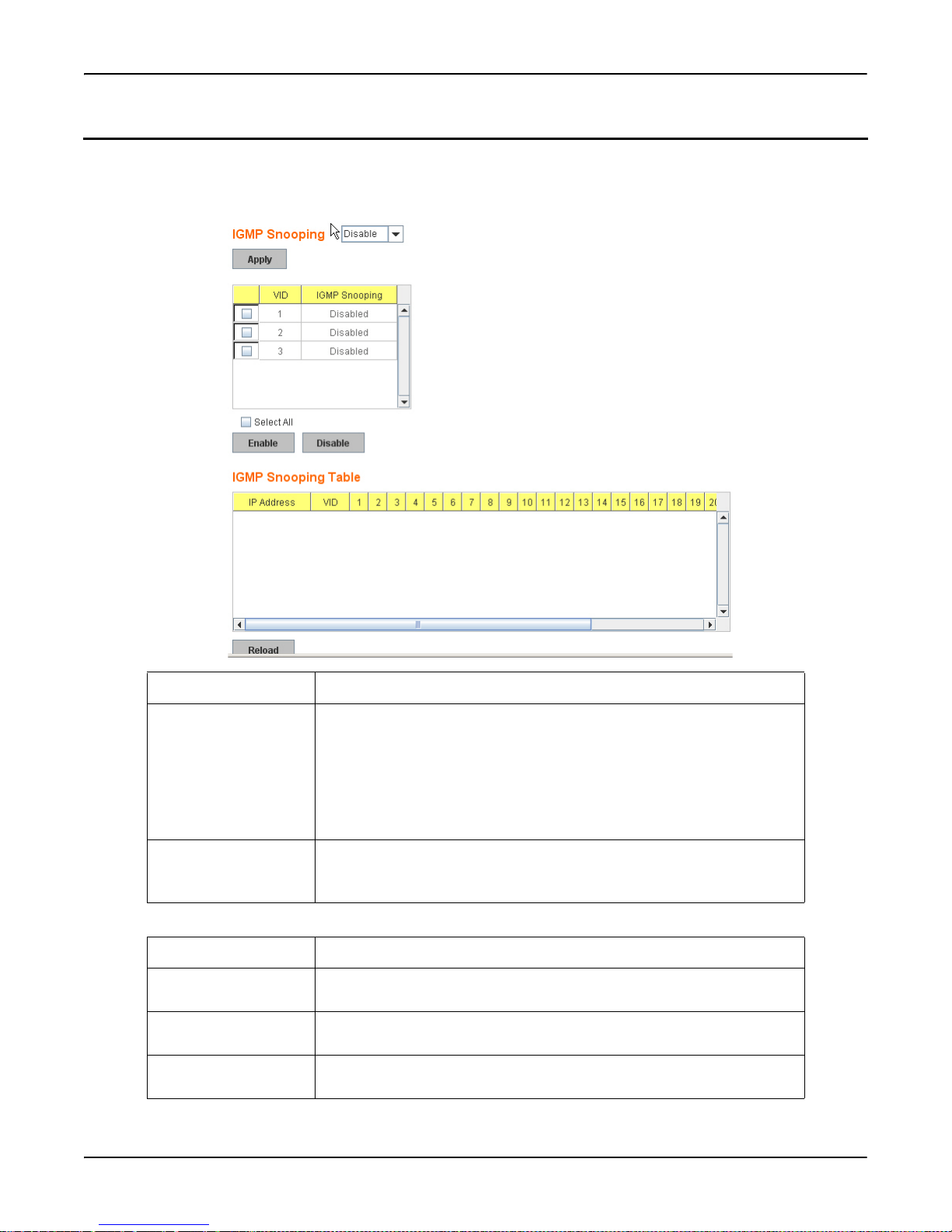
IGMP Snooping
IGMP Snooping
Use this page to enable the IGMP Snooping feature, assign IGMP Snooping for specific VLANs, and view the IGMP
Snooping table from a dynamic learnt or static that you provide. The RocketLinx ES7528 supports IGMP snooping V1/V2/V3
automatically and IGMP query V1/V2.
IGMP Snooping Description
IGMP Snooping You can select Enable or Disable. After enabling IGMP Snooping, you can
then enable IGMP Snooping for specific VLAN.
You can Enable IGMP Snooping for some VLANs so that some of the
VLANs support IGMP Snooping and others will not.
To assign IGMP Snooping to VLAN, click the check box of the VLAN ID or
click the Select All check box for all VLANs and then click Enable. You can
also Disable IGMP Snooping for certain VLANs using the same method.
IGMP Snooping Table This table displays the multicast group IP address, VLAN ID it belongs to,
and member ports of the multicast group. The RocketLinx ES7528 supports
256 multicast groups. Click Reload to refresh the table.
IGMP has three fundamental types of messages as follows:
Message Description
Query A message sent from the querier (IGMP router or switch) asking for a
response from each host belonging to the multicast group.
Report A message sent by a host to the querier to indicate that the host wants to be or
is a member of a given group indicated in the report message.
Leave Group A message sent by a host to the querier to indicate that the host has quit being
a member of a specific multicast group.
96 - RocketLinx ES7528 Industrial Managed PoE Rack Mount User Guide: 2000509 Rev. A IGMP Snooping
Page 97
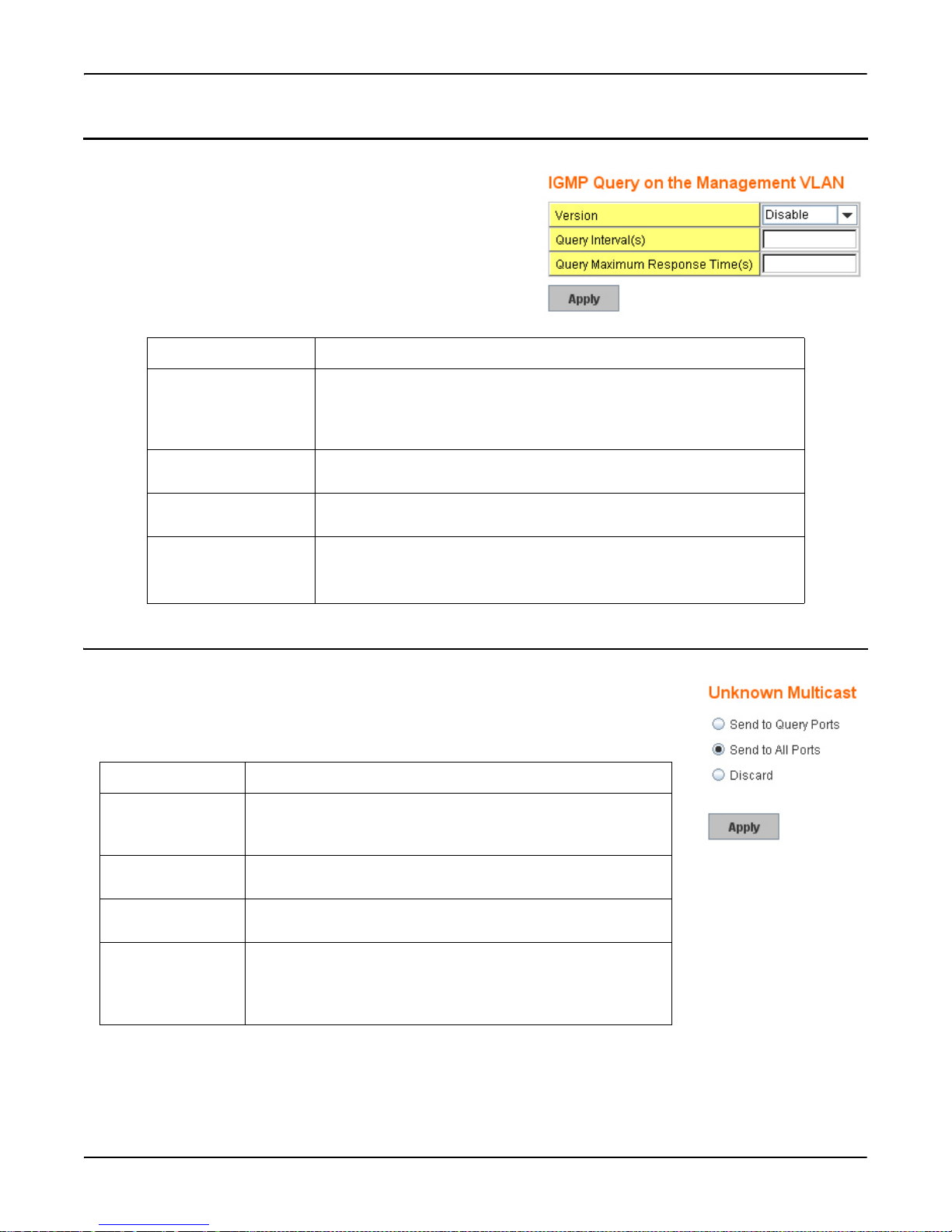
IGMP Query
Use this page to configure the IGMP Query feature. Since the
RocketLinx ES7528 can only be configured by member ports of the
management VLAN, the IGMP Query can only be enabled on the
management VLAN. If you want to run IGMP Snooping feature in
several VLANs, first check to see whether each VLAN has its own
IGMP Querier.
The IGMP querier periodically sends query packets to all end-stations
on the LANs or VLANs that are connected to it. For networks with more
than one IGMP querier, a switch with the lowest IP address becomes the
IGMP querier.
IGMP Query Description
Version Select Version 1, Version 2 or Disable. Version 1 means IGMP V1 General
Query and Version 2 means IGMP V2 General Query. The query is
forwarded to all multicast groups in the VLAN. Disable allows you to disable
IGMP Query.
Query Interval(s) The period of query (seconds) sent by querier. Enter a number between 1 and
65,535.
Query Maximum
Response Time
Apply Click Apply to apply the settings.
The span querier detect (seconds) to confirm there are no more directly
connected group members on a LAN. Enter a number between 1 and 25.
IGMP Query
Note: You must Save the settings (Page 137), if you want to maintain these
settings if the RocketLinx ES7528 is powered off.
Unknown Multicast
This page allows you to decide how to forward the unknown multicast traffic. After enabling
IGMP Snooping, the known multicast can be filtered by IGMP Snooping mechanism and
forwarded to the member ports of known multicast groups. The other multicast streams that are
not learnt is a so-called unknown multicast, the switch decides how to forward them based on the
setting of this page.
UnKnown Multicast Description
Send to Query Ports The unknown multicast is sent to the Query ports. The Query port
means the port received the IGMP Query packets. It is usually the
uplink port of the switch.
Send to All Ports The unknown multicast is flooded on all ports even if they are not
member ports of the groups.
Discard The unknown multicast is discarded. Non-member ports will not
receive the unknown multicast streams.
Apply Click Apply to apply the settings.
Note: You must Save the settings (Page 137), if you want to
maintain these settings if the RocketLinx ES7528 is
powered off.
IGMP Query RocketLinx ES7528 Industrial Managed PoE Rack Mount User Guide: 2000509 Rev. A - 97
Page 98
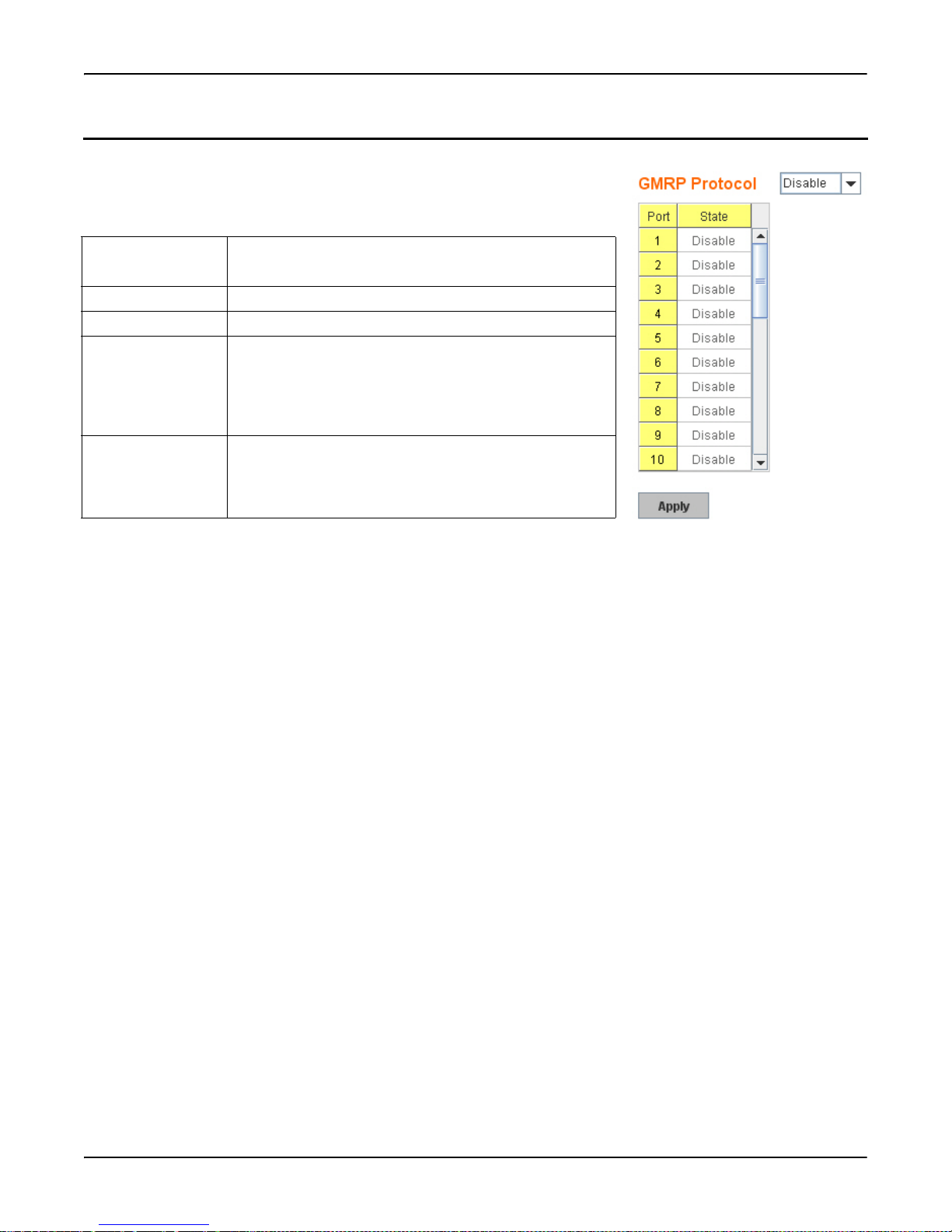
GMRP Configuration
GMRP Configuration
GARP Multicast Registration Protocol (GMRP) is a Generic Registration Protocol
(GARP) application that provides a multicast traffic management facility at layer 2
similar to what IGMP provides at layer 3. GMRP and GARP are industry-standard
protocols first introduced as part of IEEE 802.1D.
GMRP
Configuration
Description
GMRP Protocol Enable/Disable GMRP protocol.
Port The port number.
State The state of the GMRP operation on this port. The value
enabled indicates that the GMRP is enabled on this port as
long as the GMRP protocol is also enabled for this device.
When disabled, but the GMRP protocol is still enable for the
device, GMRP is disabled on this port.
Apply Click Apply to apply the settings.
Note: You must Save the settings (Page 137), if you want to
maintain these settings if the RocketLinx ES7528 is
powered off.
98 - RocketLinx ES7528 Industrial Managed PoE Rack Mount User Guide: 2000509 Rev. A GMRP Configuration
Page 99

CLI Commands for Multicast Filtering
CLI Commands for Multicast Filtering
The following table provides detailed information about command lines for multicast filtering configuration.
Feature Command Line
IGMP Snooping
IGMP Snooping Global
Switch(config)# ip igmp snooping
IGMP snooping is enabled globally. Specify on which vlans
IGMP snooping enables
IGMP Snooping VLAN
Switch(config)# ip igmp snooping vlan
VLANLIST allowed vlan list
all all existed vlan
Switch(config)# ip igmp snooping vlan 1-2
IGMP snooping is enabled on VLAN 1-2.
Disable IGMP
Snooping - Global
Disable IGMP
Snooping - VLAN
Display – IGMP
Snooping Setting
Switch(config)# no ip igmp snooping
IGMP snooping is disabled globally ok.
Switch(config)# no ip igmp snooping vlan 3
IGMP snooping is disabled on VLAN 3.
Switch# sh ip igmp
interface vlan1
enabled: Yes
version: IGMPv1
query-interval; 125s
query-max-response-time: 10s
Switch# sh ip igmp snooping
IGMP snooping is globally enabled
Vlan1 is IGMP snooping enabled
Vlan2 is IGMP snooping enabled
Vlan3 is IGMP snooping disabled
Display – IGMP Table Switch# sh ip igmp snooping multicast all
VLAN IP Address Type Ports
---- --------------- ------- ------------------------
1 239.192.8.0 IGMP fa6,
1 239.255.255.250 IGMP fa6,
CLI Commands for Multicast Filtering RocketLinx ES7528 Industrial Managed PoE Rack Mount User Guide: 2000509 Rev. A - 99
Page 100

CLI Commands for Multicast Filtering
IGMP Query
IGMP Query V1 Switch(config)# int vlan 1 (Go to management VLAN)
Switch(config-if)# ip igmp v1
IGMP Query V2 Switch(config)# int vlan 1 (Go to management VLAN)
Switch(config-if)# ip igmp
IGMP Query version Switch(config-if)# ip igmp version 1
Switch(config-if)# ip igmp version 2
Disable Switch(config)# int vlan 1
Switch(config-if)# no ip igmp
Display Switch# sh ip igmp
interface vlan1
enabled: Yes
version: IGMPv2
query-interval: 125s
query-max-response-time: 10s
Switch# show running-config
….
!
interface vlan1
ip address 192.168.250.17/24
ip igmp
no shutdown
!
…….
Unknown Multicast
Send Unknown
Multicast to Query
Ports
Send Unknown
Multicast to All Ports
Switch(config)# ip igmp snooping source-only-learning
IGMP Snooping Source-Only-Learning enabled
Switch(config)# no ip igmp snooping source-only-learning
IGMP Snooping Source-Only-Learning disabled
Switch(config)# no mac-address-table multicast filtering
Flooding unknown multicast addresses ok!
Discard All Unknown
Multicast
100 - RocketLinx ES7528 Industrial Managed PoE Rack Mount User Guide: 2000509 Rev. A CLI Commands for Multicast Filtering
Switch(config)# mac-address-table multicast filtering
Filtering unknown multicast addresses ok!
 Loading...