

Page 1
RocketModem™ ISA V.34
Hardware Installation Card
Product Overview
The RocketModem multimodem card is Hayes® compatible
and contains four or eight RJ11 modem ports, depending
on the model, that can operate at speeds up to 33.6 Kbps.
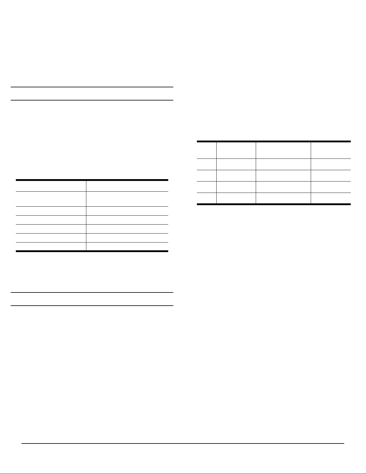
RocketModem features for this model includes:
• Four or eight RJ11 modem ports.
• Bootable diagnostic tests on the CD.
• Individual software controlled modem reset capability.
Note: See the Software Installation and Configuration
Note: If the Comtrol RocketModem is not among the
Installing the RocketModem
This RocketModem card has a DIP switch that is used to set
the I/O address. The factory default value is 180
(hexadecimal).
You will need to change the DIP switch setting on the card,
if:
• Existing peripherals in the system overlap or use the
• You are installing more than one RocketModem ISA.
To install a single RocketModem, follow these steps:
Note: For best results, we recommend installing
1. Determine if you need to change the DIP switches from
Guide for information about installing software,
and using the AT command set and the reset feature.
Characteristic RocketModem Support
Supported standards
Error correction V.42, MNP2-4, MNP10
Data compression V.42bis, MNP5
Fax group Group 3
Fax class Class 1.0 and Class 2
Reset Software controlled
modem models listed in your software applications
modem list, you can select SupraFAXModem
288(336) for fax emulation and Zoom Telephonics
Zoom V.34X for modem emulation.
default I/O value (180h).
You must change the DIP switch setting on the second
and subsequent cards.
RocketModem cards one at a time to simplify the
configuration process.
the default value of 180h. To reset the DIP switch, see
the Setting I/O Address DIP Switches section.
V.34, V.32turbo, V.32bis,
V.32, V.22bis
2. Turn off your computer and remove the system unit
cover.
3. Select an available ISA or EISA slot and remove the
slot cover. For EISA installation, see the Installing a
RocketModem on an EISA Bus section.
Note: The RocketModem ISA requires a full-length ISA or
4. Write down the Rocket Modem serial number.
5. Insert the RocketModem into the expansion slot. Make
6. Reinstall the expansion slot cover screw.
7. Connect standard RJ11 (telephone) cables between the
8. Turn on the computer and run the Diagnostics
9. After the RocketModem has successfully passed
After you have successfully installed one RocketModem,
you can install additional RocketModem cards by
repeating this process.
Installing a RocketModem on an EISA Bus
If you are installing a RocketModem in a computer with an
EISA bus, you may need to use the EISA configuration
files. You can find these in the \EISACFG directory on the
CD. The EISAREAD.TXT file contains information on
using the EISACFG files.
EISA slot.
Card
1
2
3
4
* The tag is located on the back (non-chip) of the card.
sure that it is seated securely.
Note: After you install and configure the
RocketModem ports and the phone line jacks.
program to verify that the RocketModem is installed
and working correctly. For instructions, see the
Troubleshooting and Running Diagnostics section.
diagnostics, install and configure the device driver for
your operating system using the RocketModem
Software Installation and Configuration Guide or the
README file released with the driver.
Model
Number*
RocketModem, make sure the system cover is
closed and the ventilation fan is unobstructed.
The RocketModem generates a significant
amount of heat. If you install more than one
RocketModem, you may want to add an
additional internal fan.
Serial Number* I/O Address
RocketModem™ ISA V.34 1 of 7
Page 2

Setting I/O Address DIP Switches
2 3 4 5 6 7 8
FIRST
SECOND
2 3 4 5 6 7 8
1
2 3 4 5 6 7 8
1
2 3 4 5 6 7 8
1
2 3 4 5 6 7 8
1
2 3 4 5 6 7 8
1
2 3 4 5 6 7 8
1
2 3 4 5 6 7 8
1
2 3 4 5 6 7 8
1
2 3 4 5 6 7 8
1
2 3 4 5 6 7 8
RocketModem or
RocketPort #1
DIP Switch Settings (I/O
Address Range) (Continued)
This RocketModem (and the ISA-bus RocketPort series)
use I/O address ranges at 40h (hex) intervals above the
base I/O range. If you are mixing RocketModem and
RocketPort ISA cards, you treat the cards the same for the
purpose of setting the I/O switch.
The first card requires a 68-byte I/O address range.
Subsequent cards use a 64-byte range. Most peripherals
use I/O address ranges between 0 and 3FF hex. If you have
peripherals installed above 400h, you may experience an
I/O conflict and will need to reset the DIP to an available
address for your system.
The first card installed determines the switch settings for
subsequent cards. For example, if you are installing two
cards and using the default I/O address range, you would
set the DIP switches on the cards as follows:
Example DIP Switch Settings
1st RocketModem
or RocketPort
180(hex)
2nd RocketModem
or RocketPort
RocketModem or
RocketPort #1
DIP Switch Settings (I/O
ON
1
ON
1
Address Range)
ON
100 – 143 hex
140 – 183 hex
180 – 1C3 hex
ON
ON
(Default)
380 – 3C3 hex
ON
1. If you are installing one RocketModem, set the DIP
switch as shown in this table.
2. If you are installing two RocketModem cards, follow
Step 1 for the first card, then set the DIP switches on
the second card to be the same as the switches on the
first card, except that switch 5 is off.
3. If you are installing three RocketModem cards,
follow Steps 1 and 2 for the first and second card,
then set the DIP switches on the third card to be the
same as the switches on the first card, except that
switch 6 is off.
4. If you are installing four RocketModem cards,
follow Steps 1 through 3 for the first, second, and
third cards, then set the DIP switches on the fourth
card to be the same as the switches on the first card,
except that switches 5 and 6 are off.
Port Identification
Comtrol numbers the modem ports on the
RocketModem mounting bracket as shown
in the illustration on the right. The port on
the “top” edge of the card is modem Line 1,
and the port at the “bottom” edge of the
card, nearest the bus connector, is Line 8.
A four-modem version of the RocketModem
card is also available. The four-modem
version uses the same mounting bracket
and connector block as the eight-modem
version, but ports 5 through 8 are blocked
with blank plugs.
You cannot upgrade the four-modem model
to an eight-modem model.
Modem
1
2
3
4
5
6
7
8
Hardware Installation Card 2 of 7
200 – 243 hex
240 – 283 hex
280 – 2C3 hex
300 – 343 hex
340 – 383 hex
ON
ON
ON
ON
ON
Troubleshooting and Running Diagnostics
The first step to troubleshooting a problem is to determine
that your RocketPort is functioning properly. To do so, you
can make a bootable diskette.
You need two files to make a bootable floppy diagnostic
diskette:
• The Rawrite utility that makes a bootable diagnostics
diskette.
• The diskette image file (*.i).
You can find both files on the Comtrol Software and
Documentation CD, or you can download them from the ftp
site.
Page 3

How to Make Bootable Diagnostic Diskettes
installing the device driver.
To run the diagnostics, you need to make a bootable
diagnostics diskette using a High-Density (HD), 1.44MD
diskette and using the appropriate directions for your
operating system. Contained in each Diag directory are
the following files:
• Diskette image file (*.i)
• Rawrite.exe
• Rawrite3.doc
Windows Environment
To make a bootable diagnostics diskette:
1. Obtain a formatted 1.44MB diskette.
2. Go to the appropriate Diag directory for your hardware
type and double-click on Rawrite.exe.
Note: You can quit Rawrite at any time by typing ^C or
CTRL-Break.
3. Enter the disk image source file name. For example,
150xxxxY.i, where xxxx are numbers and Y is an alphacharacter.
4. Enter the target diskette drive. For example, a.
5. Insert the formatted diskette into the target drive and
press the ENTER key.
Note: For more information about Rawrite.exe, refer to
the rawrite3.doc document in the appropriate
Diag directory.
DOS Environment
To make a bootable diagnostics diskette:
1. Obtain a formatted 1.44MB diskette.
Note: To format a diskette in drive: a, type at the DOS
prompt: format a:.
2. At the DOS prompt, enter the appropriate directory
from the CD. For example,
d<drive letter>:\<appropriate path>
3. To start Rawrite, type
<drive>\rawrite
4. Enter the disk image source file name. For example,
150xxxxY.i
where xxxx are numbers and Y is an alpha-character.
5. Enter the target diskette. For example, a
6. Insert the formatted diskette into the target drive and
press the Enter key.
Note: For more information about Rawrite.exe, refer to
the rawrite3.doc document in the appropriate Diag
directory.
UNIX Environment
To make a bootable diagnostics diskette, use the dd
command to copy the diskette image file out to a floppy
drive. For example,
dd if=<current path>/<diskette image file>of=/
dev/rfd0135ds18 (primary 3.5” drive)
dd if=<current path>/<diskette image file>of=/
dev/rfd1135ds18 (secondary 3.5” drive)
For more information about dd, please refer to your
operating system’s man pages.
Diagnostics Overview
After you make a bootable diagnostic diskette, you can use
the diagnostic program to:
• Confirm that the hardware is functioning.
• Determine resolutions to conflicts during installation.
• Provide you with the ability to stress test the cards.
For example, you may want to run the diagnostics
overnight to evaluate a possible problem. You sill need
loopback plugs for each port that you want to stress test. If
you need additional loopback plugs, you can use the
appropriate Building Loopback Plugs section in this
document to build additional loopback plugs.
Using the Diagnostics
After you have installed one or more RocketModem cards
in your computer, use the diagnostic program to establish
that the card is working, before
The diagnostic program is an operating systemindependent program that you can find on the Comtrol
Software and Documentation CD, or you can download
them form the ftp site. You must boot the system from the
diagnostic diskette in order to run the diagnostic program.
Follow these steps:
1. Insert the Diagnostics diskette into the floppy drive.
2. Turn on the computer. The diagnostic program starts
automatically on boot-up.
The diagnostic title screen appears. Note the release
number and date. You may need this information if
you contact Comtrol technical support.
3. Press any key to continue.
If you do not have any RocketModem i or
RocketModemII cards installed, a message screen
appears notifying you that you must configure the ISA
cards for the diagnostic to run.
4. Press any key to continue.
A list of ISA-bus RocketModem models appears.
5. Select the letter that corresponds to the model that you
have installed, select NOT INSTALLED if you have no
RocketModem/ISA cards in the system, or select X to
exit the diagnostic.
If you select an ISA-bus model, a list of valid I/O
addresses (A through K) appears:
a. Select the letter for the I/O address that you used
when installing the card. A list of valid IRQ
interrupts appears.
b. Select the letter for the IRQ that you used when
installing the card.
Note: Some drivers require an IRQ. If this is a new
installation, the correct entry will be I: NO IRQ.
c. The diagnostic program loops back to Step 5.
d. If you have more than one ISA RocketModem
Hardware Installation Card 3 of 7
Page 4

installed, repeat this step until you have entered
the information for all the cards. When you are
done, select NOT INSTALLED to exit this loop.
Note: Only the first card requires that the I/O address
entered in Step 5a matches the physical DIP
switch setting. For each subsequent card, select
any unused I/O address.
The list of I/O and IRQ parameters you entered
appears.
6. If the list is correct, press Y. If the information is not
correct, press N to restart the diagnostic.
The diagnostic resets and re-initializes all modems.
7. After initialization completes, an option box appears at
the bottom of the screen:
– D to run the Diagnostic
– T for Terminal Mode at 9600 baud
– M for Terminal Mode at maximum baud
– Q to QUIT
8. Press D to test the serial I/O and IRQ. (The T and M
options are discussed under the Terminal Mode
section.) The diagnostic tests each RocketModem card’s
serial I/O, IRQ, and telephone type, and displays the
results.
9. Press any key to continue. If you have more than one
card installed, the diagnostic repeats until all cards
have been tested.
10. Press any key to continue. The diagnostic displays a
summary of the test results.
11. Press any key to continue.
The diagnostic resets all modems and re-initializes all
RocketModem boards.
12. Press Y to restart the diagnostic at Step 3 (for example,
to enter the Terminal Mode), or N to quit.
If you select N, remove the diagnostic diskette from the
drive, then press the space bar or Enter key to boot the
system. Do not use the CTRL-ALT-DEL reboot
command. Use of this command may result in CMOS
errors on some systems.
Note: You use the Terminal Mode option to test modems by
dialing out using AT commands. For an example of
how to use this option, see the Terminal Mode section.
Troubleshooting
If an ISA-bus modem card fails to initialize, check to make
sure that you have selected the correct I/O address and
IRQ. If that does not solve the problem, try removing the
card and reseating it into another slot.
If you have tried any “short cuts” in running the
diagnostic, try rebooting your system from the floppy. The
diagnostic WILL NOT WORK in a “DOS over Windows”
session.
Terminal Mode
terminal mode at the maximum baud rate supported by
your RocketModem model.
1. If there are more than one RocketModems installed,
you are asked to select a card. Select a card.
2. A numbered menu listing the ports on the selected card
appears. You may also press H for help with AT
commands, R to reset a single modem, T to reset all
modems on the selected board, or X to exit.
3. Enter a port number to select a modem. The Terminal
Mode screen appears.
4. Type AT commands to communicate with the modem.
5. When you are done, press the Esc key to return to Step
2.
For example, follow these steps to test two modem ports.
This example requires that you connect phone lines to both
Ports 1 and 2.
1. Select Port 1.
2. Enter AT&F0 to initialize the modem to the factory
default parameters.
3. Enter ATS0=1 to direct the modem to answer the phone
on the first ring.
4. Press the Esc key to return to the port menu.
5. Select Port 2.
6. Enter AT&F0 to initialize the second modem.
7. Enter ATDTxxx xxxx (where xxx xxxx is the phone
number of the line connected to the first modem).
Watch and wait. The Port 2 modem should dial the
Port 1 modem and you should eventually see the
CONNECT message.
8. Press the Esc key.
9. Select Port 1. You should see RING and CONNECT
messages.
10. Any keys you press while looking at Port 1 display
when you look at Port 2. Likewise, any keys you press
while looking at Port 2 display when you return to the
Port 1 display.
11. To exit, on either of the ports enter the escape sequence
+++. This enables you to enter ATH to hang up, or any
other valid AT command string.
If you do not hang up, you can return to the still-active
connection by entering ATO.
12. To exit terminal mode and return to the port menu,
press the Esc key.
If you select either the T or M Terminal Mode option while
running the diagnostic, the diagnostic starts a simple
terminal emulation program. The T option selects a
terminal mode at 9600 baud, while the M option selects a
Hardware Installation Card 4 of 7
Page 5

Modem Cables
FCC Notices
RocketModem ports use standard telephone-type
unshielded twisted-pair cables with RJ11 modular
connectors. These can be purchased anywhere commercial
telephone products are sold.
If you choose to build your own cables, use the following
information. When building cables, use Category 3 (or
better) unshielded twisted-pair wiring.
Pin 1 Pin 4
The following table shows the connector pinouts:
RJ11 Pins Signals
1 and 4 Not used
2 Ring
3 Tip
Safety Notices
Installation of inside wire may bring you close to electrical
wire, conduit, terminals and other electrical facilities.
Extreme caution must be used to avoid electrical shock
from such facilities. Avoid contact with electrical current
by following these guidelines:
• Use tools with insulated handles.
• Do not place telephone wiring or connections in any
conduit, outlet or junction box containing electrical
wiring.
Note: Do not work on your telephone wiring at all if you
wear a pacemaker. Telephone lines carry electrical
current.
• Telephone wiring must be at least 6 feet from bare
power wiring or lightning rods and associated wires,
and at least 6 inches from other wire (antenna wires,
doorbell wires, wires from transformers to neon signs),
steam or hot water pipes, and heating ducts.
• Before working with existing inside wiring, check all
electrical outlets for a square telephone dial light
transformer and unplug it from the electrical outlet.
Failure to unplug all telephone transformers can cause
electrical shock.
• Do not place a jack where it would allow a person to
use the telephone while in a bathtub, shower,
swimming pool, or similar hazardous location.
• Protectors and grounding wire placed by the service
provider must not be connected to, removed, or
modified by the customer.
CAUTION: Do not touch telephone wiring during
lightning!
Radio Frequency Interference (RFI) (FCC 15.105)
This card has been tested and found to comply with the
limits for Class B digital devices pursuant to Part 15 of the
Federal Communications Commission rules.
The RocketModem generates, uses, and can radiate radio
frequency energy, and if not installed and used in
accordance with this card, may cause harmful interference
to radio communications. However, there is no guarantee
that interference will not occur in a particular installation.
If this equipment does cause harmful interference to radio
or television reception, which can be determined by
turning the equipment off and on, you are encouraged to
try and correct the interference by one or more of the
following measures:
• Reorient or relocate the receiving antenna.
• Increase the distance between the equipment and the
receiver.
• Connect the equipment into an outlet on a circuit
different from that to which the receiver is connected.
• Consult the dealer or an experienced radio/TV
technician for help.
Labeling Requirements (FCC 15.19)
The RocketModem complies with part 15 of FCC rules.
Operation is subject to the following two conditions:
• This device may not cause harmful interference, and
• This device must accept any interference received,
including interference that may cause undesired
operation.
Modifications (FCC 15.21)
Changes or modifications to this equipment not expressly
approved by Comtrol Corporation may void the user's
authority to operate this equipment.
Cables (FCC 15.27)
This equipment is certified for Class B operation when
used with unshielded cables.
FCC Part 68 Notice
1. This equipment complies with Part 68 of FCC rules. On
the bottom panel of the unit is a label containing the
FCC registration number, ringer equivalence number,
and the USOC jack code.
2. The RocketModem uses FCC compliant modular plugs,
it is designed to be connected to the telephone network
or premises wiring using a compatible modular jack
which is FCC Part 68 compliant.
3. If this equipment causes harm to the telephone
network, the telephone company will notify you in
advance that temporary discontinuance of service may
be required. But, if advance notice is not practical, the
telephone company will notify you as soon as possible.
Also you will be advised of your right to file a
complaint with the FCC, if you believe it is necessary.
4. The telephone company may make changes in its
facilities, equipment, operations, or procedures that
could affect the operation of the equipment. If this
happens, the telephone company will provide advance
notice in order for you to make necessary modifications
Hardware Installation Card 5 of 7
Page 6

in order to maintain uninterrupted service.
5. If the equipment is causing harm to the network, the
telephone company may request you to remove the
equipment from the network until the problem is
resolved. If so, contact Comtrol Corporation at 651631-7654.
6. No repairs are to be made by you. Repairs are to be
made only by Comtrol or its licensees. Unauthorized
repairs void the warranty and the registration.
7. This equipment may not be used for public coin phone
service provided by the Telephone Company.
Connection to Party Line Service is subject to state
tariffs. (Contact the state public utility commission,
public service commission, or corporation commission
for information.)
8. The Telephone Consumer Protection Act of 1991 makes
it unlawful for any person to use a computer or other
electronic device, including fax machines, to send any
message unless such message clearly contains in a
margin at the top or bottom of each transmitted page
or on the first page of the transmission, the date and
time it is sent, an identification of the business or other
entity, or other individual sending the message, and
the telephone number of the sending machine or of
such business, other entity, or individual. (The
telephone number provided may not be a 900 number
or any other number for which charges exceed local or
long-distance transmission charges.) In order to
program this information into your fax software, you
should refer to the manual of the Fax software being
used.
RocketModem - Canada
The RocketModem connects directly to off-premises
Common Carrier facilities using the standard two-wire
telephone connection. In some cases, the building’s inside
wiring associated with a single line individual server may
be extended by means of a certified connector assembly
(telephone extension card).
NOTICE: The Industry Canada label identifies certified
equipment. This certification means the equipment meets
telecommunications network protective, operational, and
safety requirements as prescribed in the appropriate
Terminal Equipment Technical Requirements document(s).
The Department does not guarantee the equipment will
operate to the user’s satisfaction.
Before installing this equipment, users should ensure that
it is permissible to be connected to the facilities of the local
telecommunications company. The equipment must also be
installed using an acceptable method of connection. The
customer should be aware that compliance with the above
conditions may not prevent degradation of service in some
situations.
Repairs to certified equipment should be coordinated by a
representative designated by the supplier. Any repairs or
alterations made by the user to this equipment, or
equipment malfunctions, may give the telecommunications
company cause to request the user to disconnect the
equipment.
Users should ensure for their own protection that the
electrical ground connections of the power utility,
telephone lines, and internal metallic water pipe system, if
present, are connected together. This precaution may be
particularly important in rural areas.
CAUTION: Users should not attempt to make such
connections themselves, but should contact the appropriate
electric inspection authority or electrician, as appropriate.
NOTICE: The Ringer Equivalence Number (REN) assigned
to each terminal device provides an indication of the
maximum number of terminals allowed to be connected to a
telephone interface. The termination on an interface may
consist of any combination of devices, subject only to the
requirement that the sum of the Ringer Equivalence
Numbers of all the devices does not exceed 5.
This digital apparatus meets the Class B limits for radio
noise for digital apparatus set out in the interferencecausing equipment standard entitled: “Digital Apparatus,”
ICES-003 of Industry Canada.
When connecting the RocketModem to the telephone
service, avoid contact with the telecommunications lead
wire. Grasp the insulated part of the jack, and do not
contact the back of the circuit board. Telephone wiring can
carry dangerous voltages from electrical faults or
lightning.
External Wiring
Any external communications wiring you may install
needs to be constructed to all relevant electrical codes. In
the United States this is the National Electrical Code
Article 800. Contact a licensed electrician for details.
Canada - Return Center
In Canada, contact the following Return Center:
Gandacar Consulting, Ltd
189 Lake Avenue East
Carlton Place, Ontario
Canada K7C 1J7 Phone: 800-563-5102
Hardware Installation Card 6 of 7
Page 7

Operating Conditions
Electromagnetic Compliance
This table illustrates RocketModem environmental
conditions:
Environmental Conditions Value
Air temperature:
System on
System off
0 to 40
-20 to 85
o
C
o
C
Altitude: 0 to 10,000 feet
Humidity (non-condensing):
System on
System off
8% to 80%
20% to 80%
Hardware Specifications
The following table illustrates hardware specifications:
Description Specification
Baud rate 300 to 33.6 Kbps
Bus interface ISA
Card dimensions (meets ISA
specifications)
Cards per system 4
Current consumption (+5V):
RocketModem 4
RocketModem 8
Device driver control:
Data bits
Parity
Stop bits
Heat output:
RocketModem 4
RocketModem 8
DTE speed Up to 115,200 bps
Interrupt (driver dependent)
Mean time between failures:
RocketModem 4
RocketModem 8
Modems per card 4 or 8
Modems per system 4 to 32
Power consumption:
RocketModem 4
RocketModem 8
Telco connector RJ11
Weight (card only):
RocketModem 4
RocketModem 8
13.5" by 4.2" (w x h)
1.3A max
2.2A max
7 or 8
Odd, Even, None
1 or 2
22.2 BTU/hr
37.5 BTU/hr
None, 3, 4, 5, 9, 10,
11, 12, and 15
18.3 years
11.6 years
6.5 W
11 W
12.1 oz
15.8 oz
This table lists electromagnetic compliance certifications:
Electromagnetic Compliance Status
Emission:
Canadian EMC requirements
Yes
FCC Class B Certification
Safety:
UL Listed
Yes
Technical Support
If you need technical support, contact Comtrol using one of
the following methods.
Corporate Headquarters:
• email: support@comtrol.com
• FAX: (763) 494-4199
• Phone: (763) 494-4100
FTP Site: ftp://ftp.comtrol.com
•
• Web Site: http://www.comtrol.com
Comtrol Europe:
• email: support@comtrol.co.uk
FAX: +44 (0) 1 869-323-211
•
• Phone: +44 (0) 1 869-323-220
• Web Site: http://www.comtrol.co.uk
Comtrol has a staff of technical support specialists
available to help you.
First Edition, April 17, 2000
Copyright © 2000 Comtrol Corporation.
All Rights Reserved.
Comtrol Corporation makes no representations or
warranties with regard to the contents of this reference
product or to the suitability of the Comtrol product for any
particular purpose. Specifications subject to change
without notice. Some software or features may not be
available at the time of publication. Contact your reseller
for current product information.
Trademark Notices
Comtrol and RocketModem are trademarks of Comtrol
Corporation.
RocketPort is a registered trademark of Comtrol
Corporation.
Other product names mentioned herein may be
trademarks and/or registered trademarks of their
respective owners.
2000041 Revision C
Hardware Installation Card 7 of 7
 Loading...