

Page 1

Windows XP Operating System
Device Driver Installation and
Configuration
Page 2

Trademark Notices
Comtrol, RocketModem, and RocketPort are trademarks of Comtrol Corporation.
Microsoft and Windows are registered trademarks of Microsoft Corporation.
Other product names mentioned herein may be trademarks and/or registered trademarks of their respective
owners.
Third Edition, May 8, 2003
Copyright © 2002 - 2003. Comtrol Corporation.
All Rights Reserved.
Comtrol Corporation makes no representations or warranties with regard to the contents of this document or
to the suitability of the Comtrol product for any particular purpose. Specifications subject to change without
notice. Some software or features may not be available at the time of publication. Contact your reseller for
current product information.
Document Number: 2000285 Rev. C
Page 3

Table of Contents
Overview ................................................................................................................................................................ 5
Driver Requirements ........................................................................................................................................ 5
Locating Current Drivers ................................................................................................................................. 5
Hardware Installation Documentation............................................................................................................ 5
Driver Features ................................................................................................................................................. 6
Upgrading Your Operating System to Windows XP ....................................................................................... 6
Installing the Device Driver.............................................................................................................................. 7
Installation Procedures..................................................................................................................................... 7
Upgrading the Driver (Existing Installation).................................................................................................. 9
Found New Hardware Wizard Installation (Driver Not Found) .................................................................. 15
Changing or Configuring Device Properties.................................................................................................. 19
Configuring Port Properties ........................................................................................................................... 21
Removing the Adapter and Driver ................................................................................................................. 24
Configuring Non-Plug and Play Devices...................................................................................................... 25
Installing Non-Plug and Play Devices ........................................................................................................... 25
Comtrol Tools...................................................................................................................................................... 33
Installing the Utilities (Windows 2000 and Windows XP) ........................................................................... 33
Using Test Terminal ....................................................................................................................................... 35
Using Port Monitor ......................................................................................................................................... 38
Using Peer Tracer ........................................................................................................................................... 43
Troubleshooting and Technical Support ..................................................................................................... 45
Troubleshooting............................................................................................................................................... 45
Before calling Technical Support ................................................................................................................... 45
Technical Support ........................................................................................................................................... 46
Index ..................................................................................................................................................................... 47
Table of Contents 3
Page 4

Table of Contents
Page blank to accommodate double-sided printing.
4 Table of Contents
Page 5

Overview
Hyperlinks within the document are underscored and blue; URLs or external
hyperlinks are underscored and red
Driver Requirements
The RocketPort or RocketModem adapter (ISA, PCI, Universal PCI, or
CompactPCI bus types supported) requires at least one host server running
Windows
Locating Current Drivers
The latest driver can be located for your product by using the links to the web site
or directly to the ftp site:
• Downloads Page on the web site (http://support.comtrol.com/download.asp
• ftp://ftp.comtrol.com/RPort/Drivers/
• ftp://ftp.comtrol.com/RModem/Drivers/
You can also use the device driver on the Comtrol CD shipped with your product.
To install the driver from the CD, use the menu program, and copy the driver files
to your hard drive and then go to Upgrading the Driver (Existing Installation)
Page 9.
Note: Always check the web or ftp sites to make sure that you have the current
®
XP.
driver and documentation.
.
)
on
Hardware Installation Documentation
For hardware specific information or the product overview, see the Hardware
Installation documents that are available on the Comtrol CD shipped with your
product or download the current version from the ftp/web site:
• Downloads Page on the web site (http://support.comtrol.com/download.asp
• ftp://ftp.comtrol.com/
• ftp://ftp.comtrol.com/
Overview 5
RPort/HW_Doc/
RModem/HW_Doc/
)
Page 6

Driver Features
Driver Features
This section provides information that you may need to install a device driver for a
RocketPort or RocketModem adapter (ISA, PCI, Universal PCI, or CompactPCI
bus types supported).
The driver supports up to 128 RocketPort and/or RocketModem ports per server.
Note: The critical limit is the number of ports your server can support. In most
The driver also allows you to intermix RocketPort and RocketModem ports within
the same system.
applications, this is defined by the number of RAS port supported,
which is typically 256 ports per primary server.
Upgrading Your Operating System to Windows XP
If you are upgrading your operating system to Windows XP, follow these steps:
1. Before upgrading your operating system, remove the driver from the Windows
95/98, Windows NT, or Windows 2000 operating system using the appropriate
manual (if necessary).
2. Turn off the system, remove the boards, and carefully set them aside.
3. Upgrade your system to the new Windows XP operating system.
4. Install the adapters and turn on the system. If you need information about reinstalling adapters, see Hardware Installation Documentation
5. Go to the Installation Procedures
on Page 7 to continue the installation.
on Page 5.
6 Overview
Page 7

Installing the Device Driver
The following subsections discuss driver installation and removal. It also
discusses adapter and port configuration. If you have installation problems, see
Troubleshooting
Installation Procedures
The following subsections discuss installation procedures for a variety of
installations. In many installations, Windows XP detects the adapter and installs
the default driver automatically. In some installations, you may need to upgrade
the default driver in the Windows XP system with the driver shipped on the
Comtrol CD to support a particular model.
on Page 45.
Existing Installations
Install the Hardware
Automatic Driver Installation
If you have a RocketPort or RocketModem installed and configured in your
system, make sure that you upgrade the driver before installing any new
RocketPort or RocketModem adapters. See Locating Current Drivers
the latest driver.
Use Upgrading the Driver (Existing Installation)
driver in the system. After updating the driver, install the new hardware and the
driver should automatically install the new adapter.
The first step to installing a PCI RocketPort or RocketModem adapter, is to install
the adapter. For hardware installation procedures, see Hardware Installation
Documentation on Page 5.
Note: Make sure that you install new adapters one at a time to minimize
installation problems.
If the driver installs automatically, you may need to configure the device or port
properties for your applications using the appropriate subsections:
• Configuring Device Properties
• Configuring Port Properties
Note: If you are unsure as to whether the adapter has installed automatically,
check the Device Manager to verify that the RocketPort or RocketModem
adapter displays.
(Comtrol Adapters) on Page 20
on Page 21
on Page 9 to upgrade the existing
on Page 5 for
Installing the Device Driver 7
Page 8

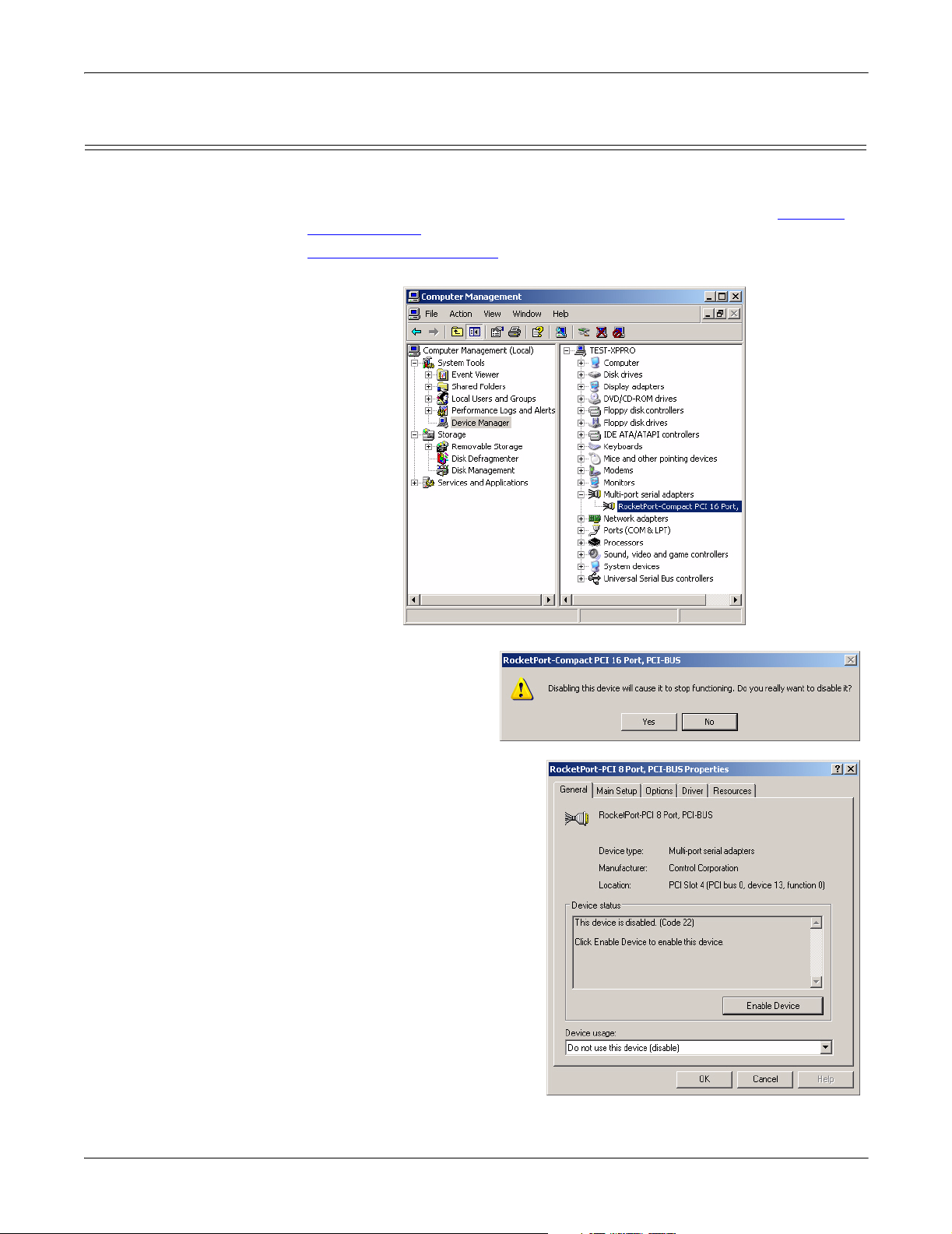
Access the Device Manager
Access the Device
Manager
You can access the Device Manager many different ways. If you are unfamiliar
with accessing the Device Manager, you can use this method:
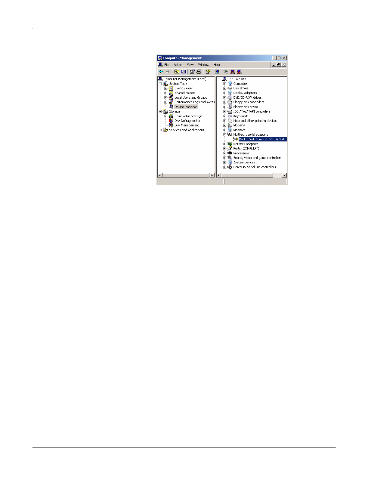
1. Open the Start button, right-click on My Computer, and select Manage.
2. Select the Device Manager.
3. Open the Multi-port serial adapters entry (click [+] to expand the list).
Manual Driver Installation
You may need to install a new driver version for a particular model because the
Found New Hardware Wizard appears. If that is the case, a driver is available on
the Comtrol CD shipped with the product or using Locating Current Drivers
Page 5. See Found New Hardware Wizard Installation
(Driver Not Found) on Page
on
15, to continue the installation.
If you want to update the default driver to the latest released driver, use
Upgrading the Driver (Existing Installation)
on Page 9, to disable the default
driver and install the latest released version.
8 Installing the Device Driver
Page 9
Upgrading the Driver (Existing Installation)
Use this procedure if you want to upgrade the driver in the Windows XP operating
system in an existing installation.
1. Unzip the file into a new subdirectory, for example: \Comtrol. See Locating
Current Drivers on Page 5 if you need a device driver.
2. Access the Device Manager
and right-click on the adapter that you want to disable.
(Page 8), open the Multi-port serial adapters entry,
Upgrading the Driver (Existing Installation)
3. Select Disable from the
list and then select Yes
when queried, Do you
really want to disable
it?
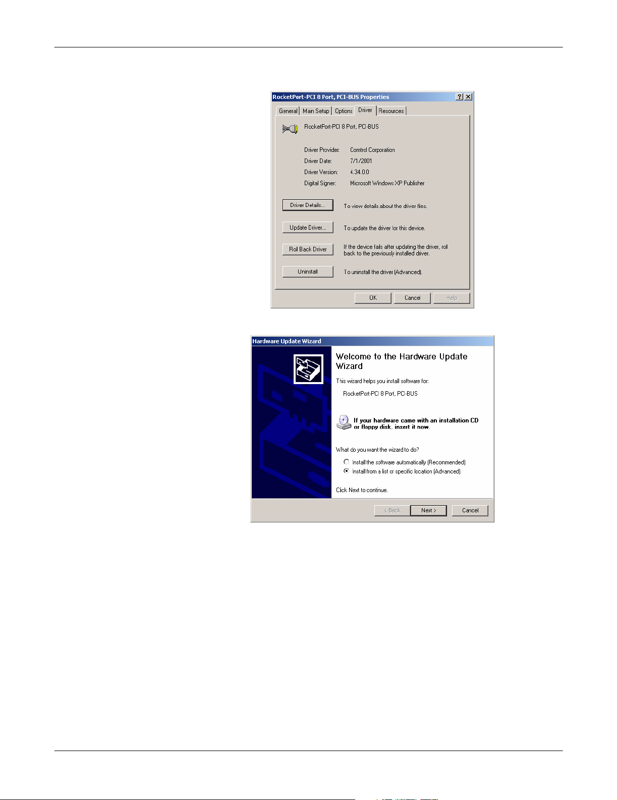
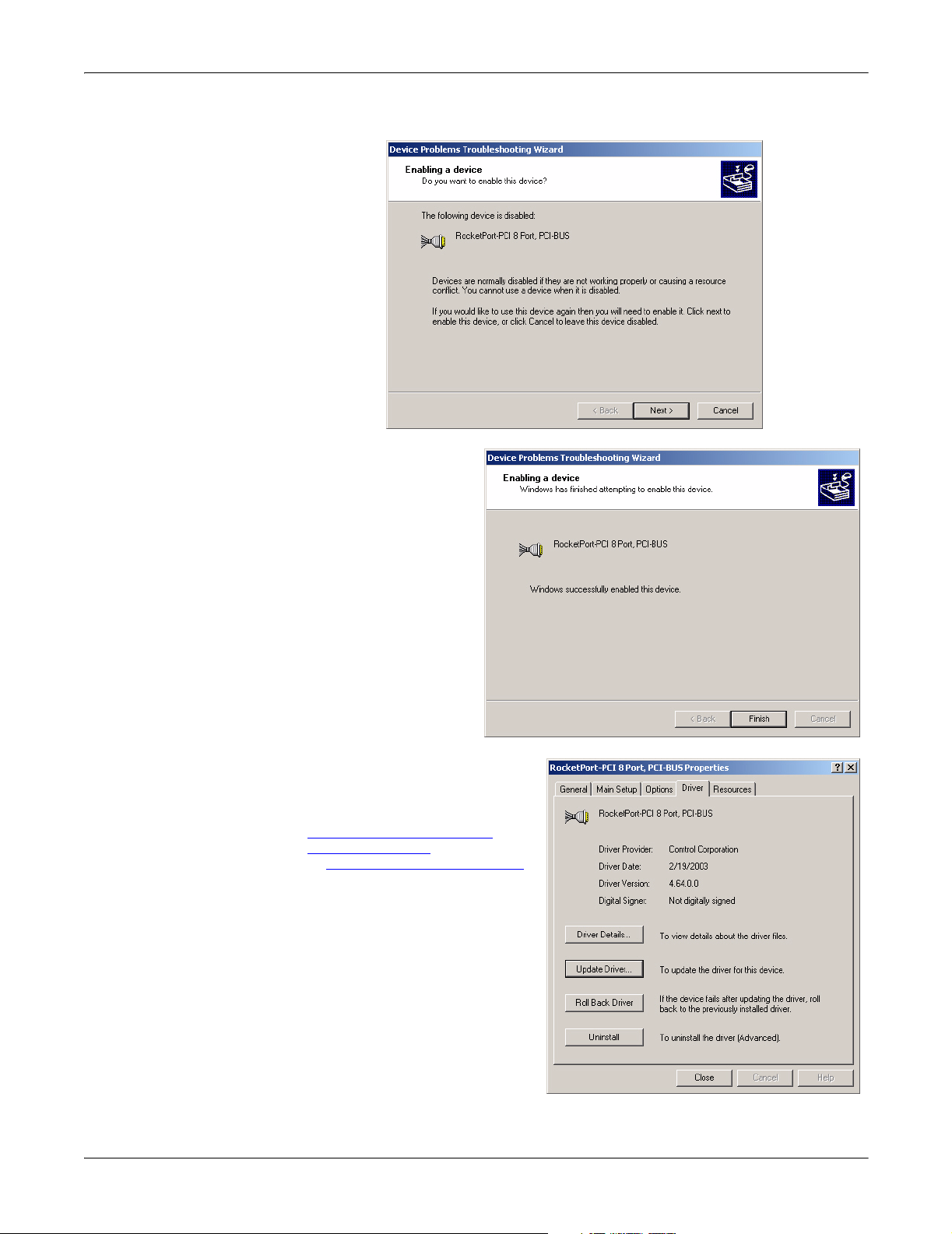
4. Double-click on the
disabled device, and select the
Driver tab.
Installing the Device Driver 9
Page 10
Upgrading the Driver (Existing Installation)
5. Select the Update Driver button.
6. Select Install from a list or specific location (Advanced) and the Next button.
10 Installing the Device Driver
Page 11
Upgrading the Driver (Existing Installation)
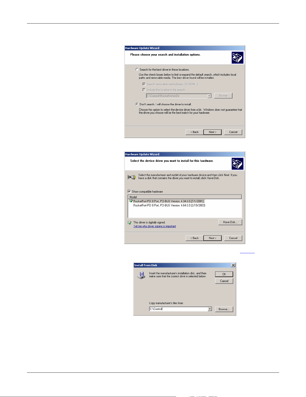
7. Select Don’t search, I will choose the driver to install and the Next button.
8. Select the Have Disk button.
9. Browse to the location of the driver file that you extracted in Step 1
and then
select the OK button.
Installing the Device Driver 11
Page 12
Upgrading the Driver (Existing Installation)
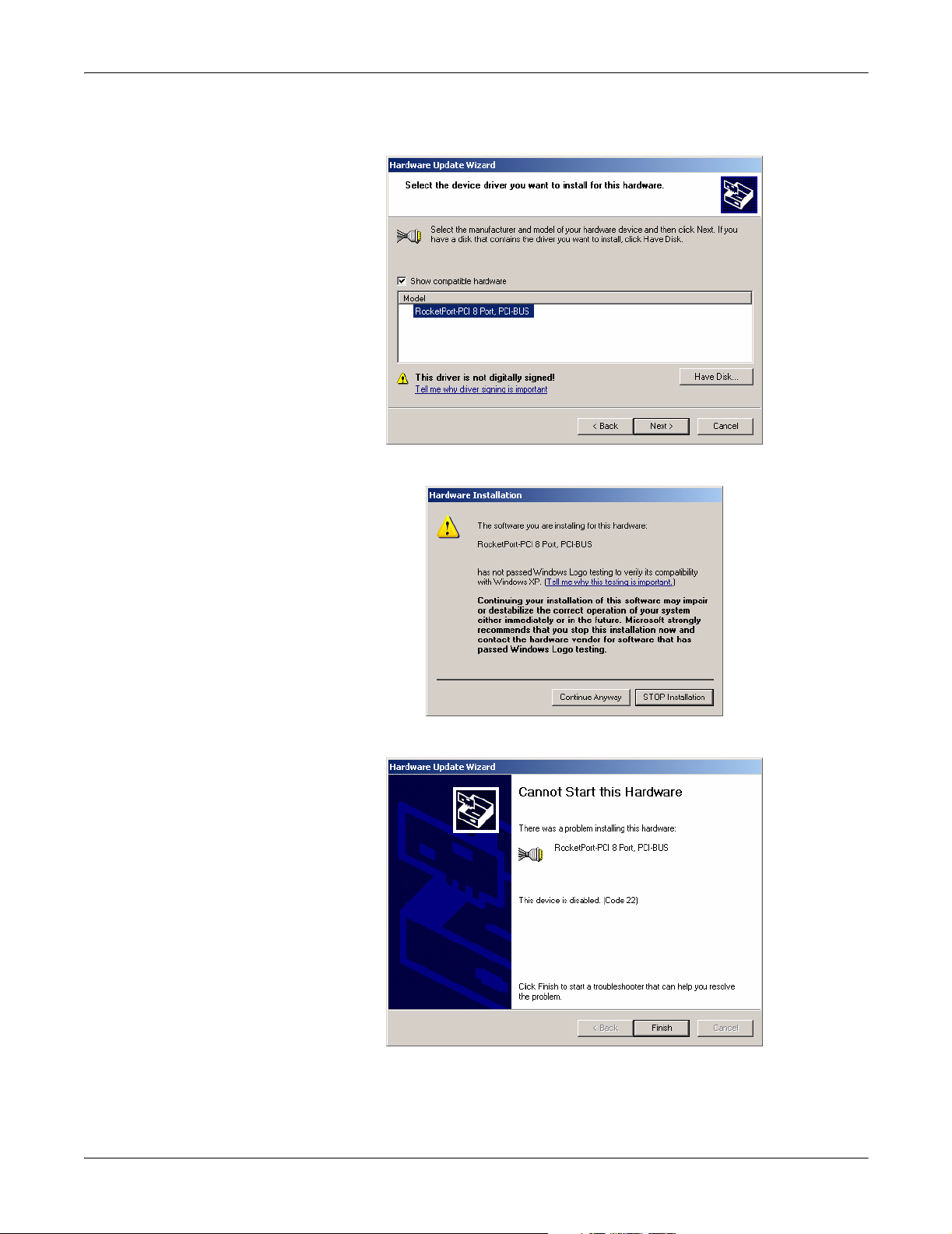
10. Select the device from the list and select the Next button to install the driver
with the default settings.
11. Select the Continue Anyway button on the Hardware Installation dialog box.
12. Select the Finish button to complete the driver installation process.
12 Installing the Device Driver
Page 13
Upgrading the Driver (Existing Installation)
13. Select Next if you want to enable the adapter.
14. Select Finish to
complete the process
of enabling the
adapter.
15. You can close this window or
configure adapter or COM port
properties using the Main
Setup and Options tabs. For
configuration procedures, see
Changing or Configuring
Device Properties on Page 19
or Configuring Port Properties
on Page 21.
Installing the Device Driver 13
Page 14
Upgrading the Driver (Existing Installation)
16. Close the Device Manager.
14 Installing the Device Driver
Page 15
Found New Hardware Wizard Installation (Driver Not Found)
Found New Hardware Wizard Installation (Driver Not Found)
If the operating system finds the adapter but not the driver, use the following
procedure when the Found New Hardware Wizard appears.
1. Copy the latest device driver to your hard drive and unzip it to a temporary
location. If you want to use the latest released device driver, see Locating
Current Drivers on Page 5.
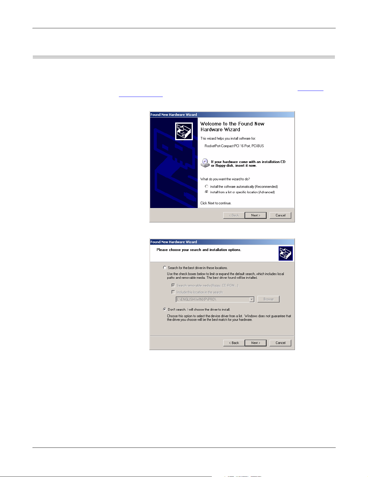
2. Select Install from a list or specific location (Advanced) and the Next button.
3. Select Don’t Search, I will choose the driver to install and the Next button.
Installing the Device Driver 15
Page 16

Found New Hardware Wizard Installation (Driver Not Found)
4. Select the Have Disk button.
5. Select the Browse button.
6. Locate the directory where the driver files are located and select Open.
16 Installing the Device Driver
Page 17

Found New Hardware Wizard Installation (Driver Not Found)
7. Select the OK button.
8. Select the Next button to start the installation process.
9. Select the Continue Anyway button to continue the driver installation.
Installing the Device Driver 17
Page 18

Found New Hardware Wizard Installation (Driver Not Found)
10. Select the Finish button and refer to the appropriate product.
RocketPort:
The new driver is now
installed and the
system will start to
configure the default
COM Ports. When it
is done, you may need
to use the following
subsections to
configure the adapter
for your environment.
• Configuring
Device Properties
(Comtrol
Adapters) on Page
20
• Configuring Port
Properties on
Page 21
RocketModem:
The new driver is now
installed and the
system will start to
configure the default
modem ports.
Windows XP notifies
you of these actions in
the lower right hand
side of the screen.
When it is done, you
may need to use the
following subsections
to configure the
RocketModem for
your environment.
• Configuring
Device Properties
(Comtrol
Adapters) on Page
20
• Configuring Port Properties
• To use this modem or modems with RRAS, see the RRAS Configuration
Overview for Windows XP document, which can be located in the RRAS_Doc
subdirectory.
11. Connect the serial devices to the ports. If the device is a plug and play device,
Windows XP will automatically detect and install the driver or drivers for your
devices.
If the device connected to the RocketPort serial ports is not a plug and play
device, see Configuring Non-Plug and Play
on Page 21
Devices on Page 25.
18 Installing the Device Driver
Page 19

Changing or Configuring Device Properties
You can change the adapter’s name and starting COM port number by accessing
the Main Setup tab. To change device properties, see Changing the Adapter Name
or the Starting COM Port Number on Page 20.
In addition, you can configure the following device properties using the Options
tab. See Configuring Device Properties
procedure.
• Verbose event log for diagnostic purposes
• Scan rate to adjust latency for timing-critical applications
• Enable RS-485 mode (if an RS-232/485 convertor is attached)
Changing or Configuring Device Properties
(Comtrol Adapters) on Page 20 for the
Access the Main Setup Tab
Before you can change or configure any port or device properties, you must access
the Main Setup tab.
1. Access the Device Manager
(Page 8), right-click the
adapter that you want to
access, and, select Properties.
2. Select the Main Setup tab.
Note: Select the Help button if
you need detailed
information about
procedures or use contextsensitive help for any field.
Installing the Device Driver 19
Page 20

Changing the Adapter Name or the Starting COM Port Number
Changing the
Adapter Name or the
Starting COM Port
Number
Configuring Device Properties (Comtrol Adapters)
Use the following procedure to change the adapter name or the starting COM port
number for the adapter.
1. Access the Main Setup Tab
(Page 19).
2. Highlight the device name and
select the Properties button.
3. After making your changes,
select the OK button and follow
any other driver prompts.
Use the following procedure to configure the adapter Device Properties.
1. Access the Main Setup Tab
(Page 19) and select the Options tab.
2. Enable the features you want
to use.
a. Verbose Event Log. Select
this check box to cause
longer messages to be sent
to the Windows XP Event
Log. This added
information can be useful
when debugging
communications and
configuration problems.
b. Scan Rate. Use this
droplist to set the driver
servicing rate. As a
general rule this is
changed only if you are
driving ports at rates in
excess of 230.4 Kbps. For
example, if you are using a
RocketPort OctaCable
running at 460.8 Kbps,
select 4 ms. If you are
running a RocketPort Plus
at 921.6 Kbps, select 2 ms.
c. To use RS-485 mode, you must have an external RS-232/485 convertor
attached to the RocketPort adapter port. Otherwise, leave this box blank.
20 Installing the Device Driver
Page 21

Configuring Port Properties
You can configure specific port properties for this adapter with these options:
• Override and lock baud rate to a specific value
• Timeout on transmit data on port close
• Map CD to DSR
• Map 2 stop bits to 1
• Wait on physical transmission before completing write
• Emulate modem hardware RING signal
• Clone all Comtrol ports for board
Use the following procedure to access the Port Properties.
1. Access the Main Setup Tab
(Page 19), select the port you
want to configure from the
Configuration list, and select
Properties.
Configuring Port Properties
2. Enable the features you want
to use.
a. Override and lock baud rate
to: This option lets you
lock selected ports to
specific baud rates.
You can select a value from
the drop list or enter the
appropriate value.
After you do so, no matter
what baud rate is selected
in a host application, the
actual rate used is the rate
specified here.
Note: Not all rates are
supported by all
Comtrol products.
See the hardware
documentation to
determine if the
adapter supports the desired rate. To use rates above 230.4 Kbps,
you must also reset the scan rate (Page 20
Installing the Device Driver 21
).
Page 22

Configuring Port Properties
b. Timeout on transmit data on port close: Use this droplist to select the length
of time to wait for data to clear the transmit buffer after a host application
has closed the port. This is typically used with peripheral devices such as
printers, to give the data sufficient time to flush through the system.
c. Map CD to DSR: This option is used in installations where there is no
connection to the port’s DSR input. Select this check box to cause the CD
input to appear as DSR to the host application, and to perform hardware
handshaking with CD rather than DSR. This is ignored if flow control is
not enabled via IOCTL_SERIAL_SET_HANDFLOW.
d. Map 2 stop bits to 1: If the application you use is hard-coded to use two stop
bits and you receive framing errors, select this check box to map 2 stop bits
to 1 bit. Otherwise, leave this box unchecked.
e. Wait on physical transmission before completing write: This option forces all
write packets to wait until the transmit data has physically completed the
transmission before returning completion to the host application. The
default mode (check box not selected) is to buffer the data in the transmit
hardware buffer, and return completion as soon as the packet is in the
buffer.
f. Emulate modem hardware RING signal: Select this check box to emulate the
ring indicator signal. If this feature is enabled, the driver monitors the
data stream and outputs a software RI whenever the RING AT command
is received.
g. Clone: If this check box is not selected, changes apply to the selected port
only. If this check box is selected, changes apply to all ports on this board.
h. Defaults: Select this to return to the driver default values.
3. Select the OK button after configuring this port or select the Clone check box
to set all of the port to these characteristics.
22 Installing the Device Driver
Page 23

Resetting RocketModem Modems
Resetting
RocketModem
Modems
1. Access the Main Setup Tab (Page 19), select the port you want to reset from
the Configuration list, and select Properties.
The Modem tab appears if the selected port is a Comtrol modem product.
2. Select the Modem tab.
Installing the Device Driver 23
Page 24

Removing the Adapter and Driver
3. Select the Reset button to reset
the selected modem to its
default (power-on) state.
Note: This resets only the
modem on the selected
modem port, on the
selected adapter. This
option cannot be used to
reset non-Comtrol
modems.
4. To use this modem or modems
with RRAS, see the RRAS
Configuration Overview for
Windows XP document, which
can be located in the
RRAS_Doc subdirectory.
Removing the Adapter and Driver
Use the following procedure to remove the existing device driver in your operating
system.
1. Access the Device Manager
(Page 8) and open the Multi-port serial adapters
entry.
2. Right-click on the adapter that you want to uninstall.
3. Select Uninstall and Yes to completely
remove the adapter.
4. Exit the Device Manager, turn off the
system, and REMOVE the adapter
from the system before re-applying
power.
24 Installing the Device Driver
Page 25

Configuring Non-Plug and Play Devices
After installing the hardware and driver for Windows XP, you can use this
discussion to configure non-plug and play modem COM ports.
Note: RocketModem models install automatically because they are plug and play
Installing Non-Plug and Play Devices
Use the following procedure to install non-plug and play devices.
1. If you have not so yet, connect the device to a RocketPort port and turn on the
2. Open the Control Panel.
devices. Other plug and play modems will install automatically.
device.
3. Go to the appropriate subsection to install non-plug and play modems or
printers:
• Installing Modems
• Installing Printers
Configuring Non-Plug and Play Devices 25
on Page 26
on Page 30
Page 26

Installing Modems
Installing Modems Use the following procedure to install non-plug and play modems.
1. If you have not done so yet, connect the modem (or modems) to the desired
RocketPort port (or ports) and turn on the modem (or modems).
Note: This may take a few minutes, depending upon your system and the
number of modems you are installing.
2. Open the Control Panel and select the Phone and Modem Options icon.
3. Select the Modems tab.
26 Configuring Non-Plug and Play Devices
Page 27

4. Select the Add button.
5. Select Don’t detect my modem. I will select it from a list and Next.
Installing Modems
Configuring Non-Plug and Play Devices 27
Page 28

Installing Modems
6. Select an appropriate standard modem model and the Next button.
Note: If you have a driver from the modem manufacturer, select Have Disk and
browse to the location of the driver.
7. Highlight the port or ports on to which you have connected modems.
28 Configuring Non-Plug and Play Devices
Page 29

Installing Modems
8. Select the Finish button to complete the modem installation.
9. Configure modem properties as necessary. For assistance, use the Windows XP
help system.
10. To use this modem or modems with RRAS, see the RRAS Configuration
Overview for Windows XP document, which can be located in the RRAS_Doc
subdirectory.
Configuring Non-Plug and Play Devices 29
Page 30

Installing Printers
Installing Printers Use the following
procedure to install a
non-plug and play
printer.
Note: If you want to
install a plug and
play printer,
connect the printer
to the appropriate
serial port and the
driver should automatically install. If it does not automatically install, use
the following procedure as a guide with the printer manufacturers
documentation.
1. Open the Control Panel and select the Printers and Faxes icon.
2. Select Next when this screen appears.
3. Select the Local printer attached to this computer item..
30 Configuring Non-Plug and Play Devices
Page 31

Installing Printers
4. Select the COM port that corresponds to the port to which the printer is
connected.
5. Select the
Manufacturer,
Printer type, and
then select Next.
Note: If you have a
driver from the
printer
manufacturer,
select Have
Disk and
browse to the
location of the
driver.
6. Optionally, enter a
printer name and
select Next.
Configuring Non-Plug and Play Devices 31
Page 32

Installing Printers
7. Select Yes if you want to print a test page.
8. Select the Finish button to complete the installation.
9. Close the Printer and
Faxes control panel.
32 Configuring Non-Plug and Play Devices
Page 33

Comtrol Tools
This section discusses the following utilities that are installed with most Comtrol
drivers for Microsoft operating systems:
• Test Terminal program (wcom32.ex e), which can be used to troubleshoot
communications on a port-by-port basis (Using Test Terminal
• Port Monitor program (portmon.exe), which checks for errors, modem control,
and status signals (Using Port Monitor
you with raw byte input and output counts.
• Peer Tracer program (peer.exe), which traces driver events (Using Peer Tracer
on Page 43).
Note: If you are using a device driver for the Windows 2000 or Windows XP
operating system, you may need to download and install these utilities.
Installing the Utilities (Windows 2000 and Windows XP)
You can download the latest Comtrol Utility package from ftp://ftp.comtrol.com/
Utilities/ or locate the Utilities directory at the root of your Comtrol CD.
Use the following procedure to install the Comtrol Utilities:
1. Run the self-extracting utility file.
You c an opt i ona l ly change the path
that you want to extract the files.
Note: Allow WinZip to run the
COM_util.exe file to start the
Utilities installation.
on Page 38). In addition, it provides
on Page 35).
The file name may be different
than the illustration.
2. Select the Next button to begin the
Comtrol Utilities installation.
Comtrol Tools 33
Page 34

Installing the Utilities (Windows 2000 and Windows XP)
3. Select the Next button to install the Utilities in the default subdirectory.
4. Select the Next button to begin the installation.
5. Select the Finish button to complete the Utilities installation.
34 Comtrol Tools
Page 35

Using Test Terminal
Using Test Terminal
WCOM32 is a terminal program that enables you to open a port, send characters
and commands to the port, and toggle the control signals.
Note: WCOM32 will not work on ports used by RAS if Remote Access Service is
running or any other application is using the port. If you are using RAS,
you must stop the service before starting WCOM32 to test RAS COM ports.
To test ports that are not used by RAS, you do not need to stop RAS.
Follow these steps:
1. Start Test Terminal (wcom32.exe) from the Comtrol program group for your
product.
Product
RocketModem and
RocketPort
RocketModem and
RocketPort
DeviceMaster RTS,
RocketPort Serial Hub ia,
and RocketPort Serial
Hub Si
Operating
System
Windows 98,
Windows NT
Windows 2000,
Windows XP
Windows 98,
Windows NT,
Windows 2000,
Windows XP
Program Group
Comtrol RocketPort RocketModem
Test Terminal
Comtrol Utilities Wcom32
wcom32.exe
Comtrol NS-Link Test Terminal
2. Select the OK button if this screen appears:
3. From the Port menu, select Open Port. A list of possible COM port numbers
displays.
4. Select the COM port you want to test.
If the COM port does not exist or if it is currently being used by another
program, a Create File Error message displays.
Comtrol Tools 35
Page 36

Testing a Comtrol Device
If the COM port is available, a terminal window appears:
Note: Notice the <loop> button in the terminal window. If this option is
activated, it is green and uppercase ( ), the COM port internal
loopback feature is activated, and the data is returned by the COM port
hardware. If this option is deactivated, it is gray and lowercase ( ),
the internal loopback is deactivated, and the data is sent out of the COM
port.
Testing a Comtrol
Device
Use the following procedure to test the Comtrol device.
1. Place a loopback plug on the COM port that you are testing. Make sure all
connectors are seated firmly and that the loop button is off.
Note: Test terminal works for RS-232 and RS-422 mode.
To build loopback plugs, see the hardware installation document for the
Comtrol device.
2. From the Port menu, select Send Test Data. The program sends out a repeating
data stream.
Note: To stop the data stream, select the Send Test Data option again.
• If the loopback plug is in place and the port is working correctly, the test
data should be echoed back to the screen.
• If the loopback plug is not in place or the port is not working correctly, no
data or garbled data is echoed back to the screen.
Note: If no characters appear, try putting the loopback plug on an adjacent
port. It may be that you have the ports mixed up.
3. If further testing is required, select Loopback
Test from the Port menu.
Note: The loopback test only works in RS-232
because it tests modem control signals
that are not present in RS-422 mode.
If the loopback plug is in place and the port is
working correctly, the system should return
the message Passed.
If the loopback plug is not in place or the port
is not working correctly, the system will return
the message Failed.
36 Comtrol Tools
Page 37

Testing RocketModem Adapters
Testing
RocketModem
Adapters
Test Terminal Modem Control Signals
The following test may be used to ensure functionality of the RocketModem.
Note: Make sure that the <loop> button is off for the following tests.
Test 1:
The following procedure checks to see if the modem responds.
1. Type atz. This should return an OK.
2. Type at&v. This should display the modem configuration.
Test 2:
The following test calls from the modem to an ordinary telephone.
1. Connect the modem to a phone line.
2. Enter atdtphonenumber, where phonenumber is the phone number of an
ordinary telephone. The telephone should ring.
3. Enter +++ath to hang up.
Test 3:
This test has one modem call another modem.
1. Connect two modems to phone lines.
2. Open two Test Terminal sessions.
3. Use one modem to call the other modem.
4. Send typed characters from one modem to the other.
The terminal window displays the modem control signals as gray
or green lights at the top of the window. The first four are inputs:
The lights are green if they are turned on, or gray if turned off.
The text on the light also changes from uppercase (CTS), which is on, to lowercase
(cts), which is off.
Note: Ring indicator is only available on the RocketPort Plus and the RocketPort
Universal PCI Quad/Octacables adapters.
The next two lights are outputs:
Note: If you have a loopback plug connected and you click on one of the outputs,
the corresponding signal is sent to the input and the input lights should
toggle accordingly.
The right most light is the loop indicator:
If this is on, the COM port internal loopback feature is activated and any
information or code entered in the terminal window loops back through the COM
port circuitry. If this is off, the COM port internal loopback is deactivated, and any
information or code entered in the terminal window is sent out of the port.
Comtrol Tools 37
Page 38

Using Port Monitor
Using Port Monitor
The Port Monitor program (portmon.exe) offers a summary of all Comtrol device
statistics in one spreadsheet view. It also enables you to verify operation of all
Comtrol device ports from a single window.
The Port Monitor display follows the familiar spreadsheet model: each COM port
is a horizontal row, and each vertical column displays a variable or value for the
respective COM port. For definitions of the abbreviations used, see Port Monitor
Variables on Page 41.
Port Monitor can also produce statistics and reports that can help you verify the
operation of the COM ports and connected peripherals. Some immediate feedback
includes:
• The state of the modem control and status signals
• Open ports
• Raw byte input and output counts obtained from the device driver
• Port errors
The available statistics include:
• Instantaneous characters per second (CPS) calculations
• Minute, hour, and day CPS averages and peaks
• Carrier detect (CD) signal runtime and transition count
Reports can be automatically generated on an hourly and/or daily basis, and can
cover all ports collectively or a separate report for each port. You can also set how
often the values are recalculated, fine-tuning thoroughness against system
efficiency, and automatically run external batch files to perform additional
processing and analysis.
Starting Port Monitor
To run Port Monitor, select Port Monitor (or Portmon.exe) from the appropriate
Comtrol program group.
Product
RocketModem and
RocketPort
RocketModem and
RocketPort
DeviceMaster RTS,
RocketPort Serial Hub ia,
and RocketPort Serial
Hub Si
Operating
System
Windows 98,
Windows NT
Windows 2000,
Windows XP
Windows 98,
Windows NT,
Windows 2000,
Windows XP
Program Group
Comtrol RocketPort RocketModem
Port Monitor
Comtrol Utilities Portmon
Portmon.exe
Comtrol NS-Link Port Monitor
The Port Monitor window appears:
Note: To change the appearance of the window, see the following discussion.
38 Comtrol Tools
Page 39

Changing Screen Appearance
Once the monitor window appears, Port Monitor is active and collecting data. If
any cumulative data has been saved from previous sessions, it is automatically
brought in and used.
Port Monitor continues to run and collect data until you terminate it, at which
point all accumulated data is automatically saved for use in the next session.
Changing Screen
Appearance
While Port Monitor is running, there are a number of commands and controls that
change the appearance of the screen.
Desired Change Procedure
Change the monitor
window font.
Change width of a
single column.
Change column
placement.
Remove a column.
Clear all fields and
reset them to null
values.
Clear any single field
except the upper left
cell.
Select Font from the Edit menu.
Left-click on the column separator (vertical) line and
drag it to the desired width.
Left-click in the middle of the column you want to
move and drag it to the desired location.
Right-click on the column you want to remove and
select Remove from the pop-up menu.
Right-click on the upper left cell in the table and select
Reset from the pop-up menu.*
Right-click on the field to be cleared and select Reset
from the pop-up menu.*
Right-click on the column now occupying the desired
location and select Add from the pop-up menu.
You are prompted to name the variable you want to
Add a column.
display, as well as other information. (See the following Column Setup discussion.)
After you click OK, the column is inserted in the
selected location and the existing column is moved to
the right.
Change other properties
of a column.
Right-click on the column and select Properties from
the pop-up menu. (See Column Setup, below.)
*The Reset command does not clear raw data from the calcs.dat file. It simply
resets the selected display fields to their null values. For more information
regarding calcs.dat, see page 41.
Column Setup When you select Add or Properties from the
column pop-up menu, the Column Setup
window appears:
•Use the Input droplist to select the
variable displayed in the column.
•Use the Type droplist to select the way in
which the value displays: either as an
integer, as an on/off state, as an integer
with a kilo, mega, or giga suffix, or as an
hh:mm:ss time stamp. This defaults to the
appropriate type for the selected Input
variable.
•Use the Name variable to change the
column heading name.
•Use the Width variable to specify the column width in characters.
Comtrol Tools 39
Page 40

Report Configuration
•Use Color0 to set the column character color when the value is zero.
•Use Color1 to set the column character color when the value is not zero.
• When done, click OK to save your changes and return to Port Monitor.
Report
Configuration
To configure reports, select
Config from the Edit menu.
The Single report options cover
all ports and are overwritten
each time the reports are
generated. The Multiple report
options generate a separate
report for each port, and each
report file is appended each
time the report is generated.
For Hour reports, use the Single
and Multiple droplists to select
whether you are generating
single or multiple reports, or
both. For each report type,
select from the following types
of data to include:
• None: no report is generated.
• Hour Data: only variables with “Hour” in the name are included.
• All Data: all variables are included.
• View Data: only variables that appear on-screen are included.
The External Program field is used to enter a command line to run another
program after the hourly reports have been generated. For example, you can use
this to run a batch file that performs custom report processing. The Test button
causes the command line to be executed immediately.
For Day reports, the single and multiple droplists behave the same, but your
choices are:
• None: no report is generated.
• Day Data: only variables with the words “Day” or “Raw” in the names are
included.
• All Data: all variables are included.
• View Data: only the variables that appear in the Port Monitor window are
included.
Likewise, the External Program field is used to enter a command line to be
executed after the daily reports have been generated.
The Update Time option allows you to set the rate at which the port information is
obtained and the calculations performed. There is a trade-off between Port
Monitor efficiency and response time. If you are using Port Monitor to view the
port activity on the screen, you may want to set the update time to 1 or 2 seconds,
so that the screen is updated frequently. If you are concerned about the monitor
program using CPU resources, set this to a higher value, (6 to 20 seconds) in order
to decrease the time required by the program to perform the calculations and
update the screen.
If Port Monitor is left active to generate reports, minimizing or reducing the
display area of the program will help reduce the CPU overhead of updating the
screen.
40 Comtrol Tools
Page 41

Port Monitor Files Port Monitor creates and uses the following files:
•portmon.vew
•calcs.dat
The default column layout is saved in portmon.vew. If you have been experimenting
with the appearance of the monitor screen, you can use the File menu Save option
to save your customized layout in another.vew file. You can retrieve this file later
by selecting the Open option from the File menu, or you can select the View Default
option from the Edit menu to retrieve portmon.vew and restore the default view.
All Port Monitor calculations are saved at program exit and on the hour in a
binary file named calcs.dat. This enables you to halt Port Monitor execution
without losing accumulated data.
Port Monitor also creates a \REPORTS directory. All hourly and daily reports are
saved in this directory, under the following names:
• hall.txt — hourly single report
• dall.txt — daily single report
• hcomx.txt — hourly multiple reports, where x is the port number
• dcomx.txt — daily multiple reports, where x is the port number
Caution: Since multiple reports append new data each time they are written, the
multiple report files grow in size. It is up to you to delete them
periodically.
Some safeguards are built into the program to avoid filling up a hard disk drive
due to growing report files. The monitoring program stops writing additional data
to the multiple reports if they reach a size of 2 MB. Also, the program will not
write out data files to the disk drive if the spare room on the drive is less than 2
MB in size.
To view or edit an hourly or daily report, select the Edit Report option from the
File menu, or use a system tool such as Microsoft Notepad.
For more information, see the Port Monitor Help file.
Port Monitor Files
Port Monitor Variables
The following table lists Port Monitor variables.
Variable Description
Open Open status, on if open, off if closed.
Cts Input CTS pin status.
Dsr Input DSR pin status.
Cd Input CD (carrier detect) pin status.
Rts Output RTS pin status.
Dtr Output DTR pin status.
TxTotal Total bytes transmitted.
RxTotal Total bytes received.
TxCPSInst
RxCPSInst
Errors
TxMinCPS
Instantaneous average of transmit characters per
second.
Instantaneous average of receive characters per
second.
Total hardware receive errors (parity, framing, and
overruns.)
Last minute average of transmit characters per
second.
Comtrol Tools 41
Page 42

Port Monitor Variables
Variable Description
RxMinCPS
Last minute average of receive characters per
second.
TxCPSMinAvMax Peak TxCPSInst for the last minute.
RxCPSMinAvMax Peak RxCPSInst for the last minute.
TxCPSHourAvMax Peak TxMinCPS for the last hour.
RxCPSHourAvMax Peak RxMinCPS for the last hour.
TxCPSDayAvMax Peak TxMinCPS for the last day.
RxCPSDayAvMax Peak RxMinCPS for the last day.
TxTotalRaw
RxTotalRaw
Total number of transmit bytes raw data from the
device driver.
Total number of receive bytes raw data from the
device driver.
TxMinCnt Count of transmit bytes sent in last minute.
TxHourCnt Transmit bytes count sent in the last hour.
TxDayCnt Transmit bytes count sent in the last day.
RxMinCnt Receive bytes count sent in the last minute.
RxHourCnt Receive bytes count sent in the last hour.
RxDayCnt Receive bytes count sent in the last day.
TxMinCntWrk Transmit bytes count sent in this minute.
TxHourCntWrk Transmit bytes count sent in this hour.
TxDayCntWrk Transmit bytes count sent in this day.
RxMinCntWrk Receive bytes count sent in this minute.
RxHourCntWrk Receive bytes count sent in this hour.
RxDayCntWrk Receive bytes count sent in this day.
TxCPSMinAvMaxWrk Peak TxCPSInst for the current minute.
TxCPSHourAvMaxWrk Peak TxMinCPS for the current hour.
TxCPSDayAvMaxWrk Peak TxHourCPS for the current day.
RxCPSMinAvMaxWrk Peak RxCPSInst for the current minute.
RxCPSHourAvMaxWrk Peak RxMinCPS for the current hour.
RxCPSDayAvMaxWrk Peak RxHourCPS for the current day.
CDRuns Carrier detect turn-on count.
CDDayRuns Carrier detect turn-on count in the last day.
CDDayRunsWrk Carrier detect turn-on count in the current day.
CDRunTime Time in seconds carrier detect has been on.
CDHourRunTime
CDDayRunTime
Time in seconds carrier detect has been on in the
last hour.
Time in seconds carrier detect has been on in the
last day.
CDHourRunTimeWrk Time in seconds carrier detect has been on this hour.
CDDayRunTimeWrk Time in seconds carrier detect has been on this day.
StatusFlags Bit flags, Open, CTS, DSR, CD, RTS, DTR
42 Comtrol Tools
Page 43

Using Peer Tracer
Using Peer Tracer
Variable Description
TxPkts Raw count of total transmit packets sent.
RxPkts Raw count of total receive packets sent.
OverrunErrors Total count of receive overrun errors.
FramingErrors Total count of receive framing errors.
ParityErrors Total count of receive parity errors.
OverrunErrorsRaw
FramingErrorsRaw
ParityErrorsRaw
Total count of receive overrun errors, from the
device driver.
Total count of receive framing errors, from the
device driver.
Total count of receive parity errors, from the device
driver.
The Peer Tracer program (peer.exe) is specifically designed to view the internal
operations of the device driver for the purpose of troubleshooting communications
on Windows NT, Windows 2000, and Windows XP systems. Peer enables you to see:
• Receive and transmit data
• Internal driver event traces
• Advanced configuration and status information
Like Test Ter mina l, Peer acts as a simple terminal session, and is used to send and
receive text information to and from the device driver. To use Peer, you type in
commands, and status and information are sent back.
Unlike Test Terminal, Peer enables you to keep a continuous log of the commands
sent and the results received in a file named peer.log. Comtrol Technical Support
may ask you to run Peer in order to help diagnose reported problems.
Starting Peer Peer Tracer does not appear in most Comtrol program groups and you may need to
start the application from the Windows Explorer. Use the table below to determine
whether you can start Peer from a program group or where to locate the
executable.
Product
DeviceMaster RTS,
RocketPort Serial Hub ia,
RocketPort Serial Hub Si
RocketModem and
RocketPort
RocketModem and
RocketPort
Operating
System
Starting Peer
Windows NT,
Windows 2000,
\WINNT\system32\rpshSi\peer.exe
Windows XP
Windows NT \WINNT\system32\rocket\Peer.exe
Windows 2000,
Windows XP
Comtrol Utilities peer peer.exe
To start Peer, you may need to open
the Windows Explorer, access a
specific directory, and double-click
on peer.exe or start peer using the
Comtrol Utilities program group.
The Peer Tracer window displays (at
right).
Comtrol Tools 43
Page 44

Log Functions
Log Functions All logging functions are found under the File menu. To start keeping a log, select
Log to Disk from the File menu. The other options on this menu are View Disk Log,
Clear Disk Log, Clear Screen, and Exit.
Using Peer To use peer, simply type in commands at the : prompt. (It may be necessary to
press Enter to make the : prompt appear.) For example, to examine COM5, type:
PORT COM5 <Enter>
To gather some information about the port, type: STAT <Enter> . This should
return details about the port.
To turn on monitoring of any calls into driver (events), type: MON EV <Enter>
To send strings and commands to attached peripherals—for example, to send
“ATH0” to a modem—type: SEND ATH0 <Enter>. A return and linefeed are always
appended to each string sent.
Other Peer
Enter commands at the : prompt and follow each command with Enter.
Commands
Command Effect
MON TX Monitor data being transmitted through the selected port.
MON RX Monitor data being received through the selected port.
M Turn off all monitoring.
? Display Peer Tracer command summary.
PORT COMxx Change port being examined to COMxx.
Keep in mind that all commands are processed in the device driver, and that Peer
simply acts as a conduit for this information.
For more information, see the Peer.hlp help file.
44 Comtrol Tools
Page 45

Troubleshooting
Troubleshooting and Technical Support
This section contains troubleshooting information for your RocketPort or
RocketModem adapter and how to contact Technical Support.
If you are having trouble with a RocketPort or RocketModem, try the following.
Note: Most customer problems reported to Technical Support
or network problems.
1. Verify that you are using the correct types of cables in the correct places and
that all cables are tightly connected. See Hardware Installation
Documentation on Page 5 to verify cabling.
2. Verify that you are addressing the port correctly. In many applications, device
names above COM9 require the prefix \\.\ to be recognized. For example, to
reference COM20, use \\.\COM20 as the file or port name.
3. Create the bootable diagnostic diskette and run the diagnostics. See the
Hardware Installation Documentation
creating and running the bootable diagnostic diskette.
4. Use the section titled, Comtrol Tools
can use to diagnose problems.
5. Enable the V erbose Event Log feature (Page 21) under the Options tab and then
reboot the server.
on Page 5 for information about
on Page 33, to install utilities that you
are traced to cabling
Before calling Technical Support
Comtrol has a staff of support technicians available to help you. You should review
Troubleshooting before calling Technical Support. If you call for Technical
Support, please have the following information available.
Adapter type
Adapter serial number
Driver part number and revision or version
Server computer make, model, and speed
Other serial port adapters installed in the
server and their COM port numbers
Devices connected to the adapter
Item Information
Troubleshooting and Technical Support 45
Page 46

Technical Support
Technical Support
If you need technical support, contact Comtrol using one of the following methods.
Contact
Method
Corporate
Headquarters
Comtrol Europe
FAQ/Online http://support.comtrol.com/support.asp
Downloads http://support.comtrol.com/download.asp
Email support@comtrol.com support@comtrol.co.uk
Web site http://www.comtrol.com http://www.comtrol.co.uk
Fax (763) 494-4199 +44 (0) 1 869-323-211
Phone (763) 494-4100 +44 (0) 1 869-323-220
46 Troubleshooting and Technical Support
Page 47

Index
accessing
Device Manager
adapter
device properties
adapter name
changing 20
application
port addressing format
8
20
45
B
A
baud rates
lock above 230.4 Kbps
over 230.4 Kbps 20
bootable diagnostic diskette 45
21
C
changing
adapter name 20
device properties 19
starting COM port number 20
Clone ports option 22
Column Setup
portmon
COM port number
changing
commands
Peer Tracer 44
portmon 39
Comtrol
contact information 46
configuring
device properties
port properties 21
39
20
20
D
Device Manager
how to access 8
device properties
changing
configuring 20
devices
installing non-plug and play
diagnostics
hardware
installing utilities 33
disabling
driver
documents
downloading the latest
downloading
latest documents
latest driver 5
driver 6
disabling 9
downloading the latest 5
features 6
installation
19
25
45
9
5
5
automatic 7
first step 7
manual 8
not found 15
requirements 5
upgrading 9
DSR
no input
22
E
email support 46
Emulate modem hardware RING signal 22
existing installations
before adding adapters
existing systems
upgrading to Windows XP
7
6
F
features 6
files
portmon 41
Found New Hardware Wizard 15
H
hardware
diagnostics
installation documents 5
45
I
input counts
portmon
installation
existing systems
first step 7
Found New Hardware Wizard 15
hardware documents 5
modem
modems
non-plug and play devices 25
non-plug and play printer 30
procedures 7
test utilities 33
IOCTL_SERIAL_SET_HANDFLOW 22
38
7
plug and play 18
non-plug and play 26
L
loopback test 36
M
Main Setup tab 19
Map 2 stop bits to 1 22
Map CD to DSR 22
Modem
modem
modem control signals
23
tab
installation
non-plug and play 26
plug and play 18
testing
37
47
Page 48

Index
modems
testing
monitor
ports
37
38
N
non-plug and play
device installation
25
O
online support 46
output counts
portmon
Override and lock baud rate to 21
38
P
Peer Tracer 43
commands 44
peripheral devices
transmit buffer
plug and play device installation 18
Port Monitor
variables
port monitor
commands
files 41
program 38
port name
addressing format
port properties
configuring
printer
installing non-plug and play 30
22
41
39
45
21
R
report configuration
portmon 40
reports
portmon
REPORTS directory
portmon
Reset RocketModem modems 23
resetting
RocketModem modems
ring indicator signal 22
RocketModem
resetting modems
testing modems 37
RRAS
configuration overview
RS-232/485 convertor 20
RS-485 mode 20
38
41
23
23
18
scan rate 20
serial devices
connection
servicing rate 20
software
RI
22
starting COM port number
changing
status signals
portmon
stop bits
using 2
18
20
38
22
T
S
Technical Support
before calling
test
loopback
test terminal 35
testing
COM ports 35
RocketModem 37
terminal modem control signals 37
Timeout on transmit data on port close 22
transmit buffer 22
troubleshooting 45
communications 43
installing test utilities 33
45
36
U
upgrade
driver
9
using
Peer 44
port monitor 38
test terminal 35
utilities
installing
33
V
variables
portmon
verbose event log 20
41
W
Wait on physical transmission before completing write
WCOM32 35
web site
web support 46
Windows XP event log 20
write packets
22
download page
wait
22
5
48 Index
 Loading...