

Page 1

Modbus®/TCP User Guide
Page 2

Trademark Notices
Document Number: 2000447 Rev I
Comtrol, DeviceMaster, and PortVision are registered trademarks of Comtrol Corporation.
Concept is a trademark of Schneider Electric.
Modbus is a registered trademark of Schneider Electric.
PLC is a registered trademark of Allen-Bradley Company, Inc.
Ethernet is a registered trademark of Digital Equipment Corporation, Intel, and Xerox Corporation.
Portions of SocketServer are copyrighted by GoAhead Software, Inc. Copyright © 2001. GoAhead Software,
Inc. All Rights Reserved.
Windows is a registered trademark of Microsoft Corporation in the United States and/or other countries.
Other product names mentioned herein may be trademarks and/or registered trademarks of their respective
owners.
Eighth Edition, July 17, 2013
Copyright © 2005-2013. Comtrol Corporation.
All Rights Reserved.
Comtrol Corporation makes no representations or warranties with regard to the contents of this document or
to the suitability of the Comtrol product for any particular purpose. Specifications subject to change without
notice. Some software or features may not be available at the time of publication. Contact your reseller for
current product information.
Page 3

Table of Contents
Chapter 1. Introduction........................................................................................................7
1.1. Audience ................................................................................................................................................... 7
1.2. Comtrol Modbus Solutions................................................................................................................... 7
1.3. Product Overview .................................................................................................................................. 8
1.4. Modbus/TCP Firmware ......................................................................................................................... 8
1.4.1. Traditional Modbus/TCP System Architecture (Firmware V2.x) .................................................. 8
1.4.2. Enhanced Modbus/TCP System Architecture (Firmware 3.x) ....................................................... 9
1.4.3. Advanced Modbus System Architecture (Firmware 5.x) .............................................................. 10
1.4.4. Modbus/TCP Multi-Mode Connectivity ......................................................................................... 11
1.4.4.1. PLC Master/DeviceMaster UP Slave Mode ......................................................................... 11
1.4.4.2. PLC Slave/DeviceMaster UP Master Mode ......................................................................... 11
1.4.4.3. Dual Master (Virtual Peer-to-Peer) - Write Mode ............................................................... 12
1.4.4.4. Dual Master (Virtual Peer-to-Peer) - Read Mode (Dual Polling) ........................................ 12
1.4.4.5. Filtering and Data Extraction Functionality (Patent Pending) ......................................... 13
1.5. Definitions and Terms......................................................................................................................... 14
1.5.1. Data Type Definitions .................................................................................................................... 14
1.5.2. Glossary........................................................................................................................................... 14
1.6. Locating Updated Software and Documents ................................................................................. 15
1.7. Modbus/TCP Application Setup ........................................................................................................ 15
Chapter 2. Programming Interface..................................................................................17
2.1. Overview................................................................................................................................................. 17
2.1.1. Modbus Master Requirements ....................................................................................................... 17
2.1.2. What is Modbus/RTU?.................................................................................................................... 18
2.1.3. What is Modbus/ASCII? ................................................................................................................. 18
2.1.4. What is Modbus/TCP? .................................................................................................................... 19
2.2. Raw Data Interface .............................................................................................................................. 19
2.2.1. Supported Modbus Messages ......................................................................................................... 19
2.2.2. Serial Port Raw/ASCII Interface ................................................................................................... 20
2.2.3. Ethernet Device Raw/ASCII Interface .......................................................................................... 21
2.2.4. Raw/ASCII Transfer Modes ........................................................................................................... 21
2.2.4.1. Data-Stream Mode ................................................................................................................ 21
2.2.4.2. Command/Response Mode .................................................................................................... 22
2.2.5. Receive Data Message (Raw Data) ................................................................................................ 23
2.2.5.1. Format.................................................................................................................................... 23
2.2.5.2. Communication Methodology (Receive Raw Data in Slave Mode) ..................................... 24
2.2.5.3. Communication Methodology (Receive Data Master Mode) ............................................... 24
2.2.6. Transmit Data Message (Raw Data) ............................................................................................. 25
2.2.6.1. Format.................................................................................................................................... 25
2.2.6.2. Communication Methodology (Transmit Raw Data Slave Mode) ...................................... 26
2.2.6.3. Communication Methodology (Transmit Data Master Mode) ............................................ 26
2.2.7. Sequence Number Messages (Raw Data) ......................................................................................27
2.3. I/O Scanner (Raw Data) ...................................................................................................................... 27
2.4. Modbus/RTU and Modbus/ASCII To-Slaves Protocol Interface ................................................ 29
2.4.1. Communication Methodology......................................................................................................... 29
2.4.2. Modbus Slave Device Search Methodology ...................................................................................30
2.5. Retrieve Statistics Message ............................................................................................................... 31
DeviceMaster UP Modbus/TCP User Guide: 2000447 Rev. I Table of Contents - iii
Page 4

Table of Contents
Chapter 3. Embedded Configuration Pages...................................................................33
3.1. Overview................................................................................................................................................. 33
3.2. Embedded Web Pages Overview ....................................................................................................... 34
3.3. Serial Device Configuration Page .................................................................................................... 35
3.3.1. Edit Serial Port Configuration Page.............................................................................................. 35
3.3.2. Serial Configuration ....................................................................................................................... 36
3.3.3. General Protocol Settings............................................................................................................... 37
3.3.4. Modbus Slave and Raw-Data Device Settings .............................................................................. 38
3.3.5. Serial Port Packet ID Settings (Raw-Data Only).......................................................................... 39
3.4. Ethernet Device Configuration Page............................................................................................... 41
3.5. Edit Socket Port Configuration Page .............................................................................................. 42
3.5.1. Device TCP Connection Configuration .......................................................................................... 42
3.5.2. Socket Packet ID Settings .............................................................................................................. 44
3.6. Common Configuration Areas (Serial or Ethernet Device) ....................................................... 47
3.6.1. Serial Modbus Master and Modbus/TCP Settings........................................................................ 47
3.6.2. Modbus/TCP Master Rx/Tx Settings ............................................................................................. 49
3.6.3. Filtering/Data Extraction Configuration....................................................................................... 51
3.6.4. Application TCP Connection Configuration.................................................................................. 54
3.6.5. Saving Port Options........................................................................................................................ 56
3.7. Edit Network Configuration Page.................................................................................................... 57
3.8. Edit Security Configuration Page .................................................................................................... 58
3.8.1. Client Authentication ..................................................................................................................... 59
3.8.2. Configuring Security ...................................................................................................................... 59
Chapter 4. Diagnostic and Statistics Pages ...................................................................61
4.1. Communication Statistics .................................................................................................................. 62
4.2. PLC Interface Diagnostics ................................................................................................................. 68
4.3. Display All Modbus Slave Devices.................................................................................................... 71
4.4. Display Serial Logs .............................................................................................................................. 73
4.5. Display Ethernet Device Logs ........................................................................................................... 74
Chapter 5. Alias Device ID Functionality.......................................................................75
5.1. Overview................................................................................................................................................. 75
5.2. Alias Modbus Device ID Configuration/Status.............................................................................. 77
5.2.1. Alias Modbus Device ID Configuration/Status Page .................................................................... 77
5.2.2. Add/Modify Alias Device ID Configuration Page .......................................................................... 78
5.2.3. Edit Alias Device ID Configuration Page ...................................................................................... 79
5.2.4. Delete Alias Device ID Configuration Page .................................................................................. 80
5.2.5. Delete All Alias Device ID Configurations Page...........................................................................81
Chapter 6. Troubleshooting and Technical Support ...................................................83
6.1. Troubleshooting Checklist ................................................................................................................ 83
6.2. General Troubleshooting.................................................................................................................... 84
6.3. Technical Support ................................................................................................................................ 84
iv - Table of Contents DeviceMaster UP Modbus/TCP User Guide: 2000447 Rev. I
Page 5

Table of Contents
Appendix A. Programming the PLC via Concept .........................................................85
A.1. Overview ................................................................................................................................................ 85
A.1.1. What is Concept?............................................................................................................................ 85
A.1.2. Requirements ................................................................................................................................. 85
A.1.3. Example Program Considerations (Raw Data) ............................................................................ 85
A.2. Concept Program Screens ................................................................................................................. 86
A.2.1. Processor and Ethernet Setup ....................................................................................................... 86
A.2.2. Message Screens............................................................................................................................. 87
A.2.2.1. Read Serial Data via Read Holding Registers Message ..................................................... 88
A.2.2.2. Transmit Serial Data via Write Multiple Registers Message ............................................ 89
A.2.2.3. Set Receive Sequence Number via Write Multiple Registers Message ............................. 90
A.2.2.4. Set Transmit Sequence Number via Write Multiple Registers Message .......................... 91
A.2.2.5. Read Serial Port Statistics via Read Holding Registers Message ..................................... 92
A.2.2.6. Modbus/TCP Slot/Index and DeviceMaster UP IP Address Definition ............................. 93
A.2.3. Concept Example Programs .......................................................................................................... 94
A.2.3.1. LPBKCNCP .......................................................................................................................... 94
A.2.3.2. SCANCNCP .......................................................................................................................... 94
A.2.3.3. Setting up and Running the Concept Example Programs ................................................. 95
Appendix B. LPBKCNCP Example Program ...............................................................103
Appendix C. SCANCNCP Example Program ...............................................................109
DeviceMaster UP Modbus/TCP User Guide: 2000447 Rev. I Table of Contents - v
Page 6

Table of Contents
vi - Table of Contents DeviceMaster UP Modbus/TCP User Guide: 2000447 Rev. I
Page 7

Chapter 1. Introduction
This User Guide provides detailed information about the following topics:
• Programming Interface
• Embedded Configuration Pages
• Diagnostic and Statistics Pages
• Programming the PLC via Concept
• LPBKCNCP Example Program
• SCANCNCP Example Program
The DeviceMaster UP Hardware Installation and Configuration Guide
• Connecting the hardware and devices
• Programming the DeviceMaster UP IP address,
• Uploading Modbus/TCP firmware
The Modbus/TCP
procedures.
See Locating Updated Software and Documents
tools.
Interface Configuration Quick Start provides embedded web page configuration
on Page 17
on Page 33
on Page 61
on Page 85
on Page 103
on Page 109
provides the following information:
on Page 15 to locate the latest firmware, documentation, and
1.1. Audience
The primary audience of this document is the person responsible for installing the DeviceMaster UP and
programming the PLC. This guide assumes you are familiar with the following topics:
• Windows operating system
• Modbus/TCP, Modbus/RTU, and/or Modbus/ASCII
• A PLC, SCADA System, or OPC Server that communicates with Modbus/TCP, Modbus/RTU, or Modbus/
ASCII
- Raw/ASCII devices such as barcode scanners, weigh scales, and printers
- Modbus/RTU and/or Modbus/ASCII slave devices.
1.2. Comtrol Modbus Solutions
If you ordered the Modbus part number for your DeviceMaster UP, Modbus/TCP is loaded on the
DeviceMaster UP by default. You may want to review our other Modbus solutions to make sure that the
feature rich Modbus/TCP application is what you want to use. Optionally, Modbus Router or Modbus Server
may by more effective for your particular environment.
The Comtrol web site provides information about the differences between the three Modbus solutions:
• M
ODBUS/TCP
• M
ODBUS SERVER
• M
ODBUS ROUTER
In addition, the DeviceMaster UP product CD and ftp site also provide these documents for your reference.
DeviceMaster UP Modbus/TCP User Guide: 2000447 Rev. I Chapter 1. Introduction - 7
Page 8
Product Overview
The following links function if you are reading this document from the ftp site or CD.
Note: Optionally, open the CD and click Modbus. The main page (
links to these documents.
• Modbus Controller to Controller Communication
• Modbus Solution Examples
• Providing Read-Only Modbus Protection
• Resolving Modbus Device ID Conflicts
If Modbus Server or Modbus Router is a better solution, you can
corresponding documentation.
up_modbus_family_main.htm) provides
DOWNLOAD the appropriate firmware and
1.3. Product Overview
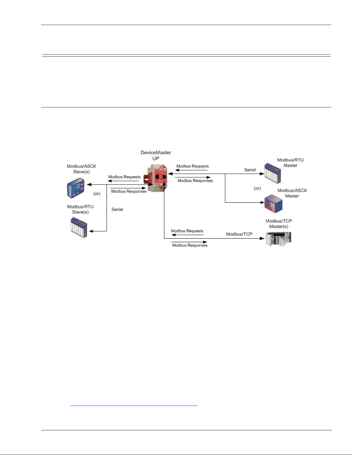
The DeviceMaster UP operates as a highly versatile Modbus gateway when the Modbus/TCP firmware is
uploaded to the DeviceMaster UP. The DeviceMaster UP provides Modbus/TCP, Modbus/RTU, Modbus/
ASCII, and Ethernet TCP/IP controller interfaces to both serial and Ethernet TCP/IP raw/ASCII devices, and
both Modbus/RTU and Modbus/ASCII slave devices.
Your particular DeviceMaster UP model may or may not have the Modbus/TCP firmware loaded (depending
on the model you purchased).
Note: Models that have Modbus/TCP loaded on the DeviceMaster UP are identified in PortVision DX and the
DeviceMaster UP is labeled accordingly.
1.4. Modbus/TCP Firmware
The following subsections provide information for existing users who may or may not want to update systems
with the advanced Modbus/TCP firmware 5.0x. For new users, the following subsections provide Modbus
system architecture information.
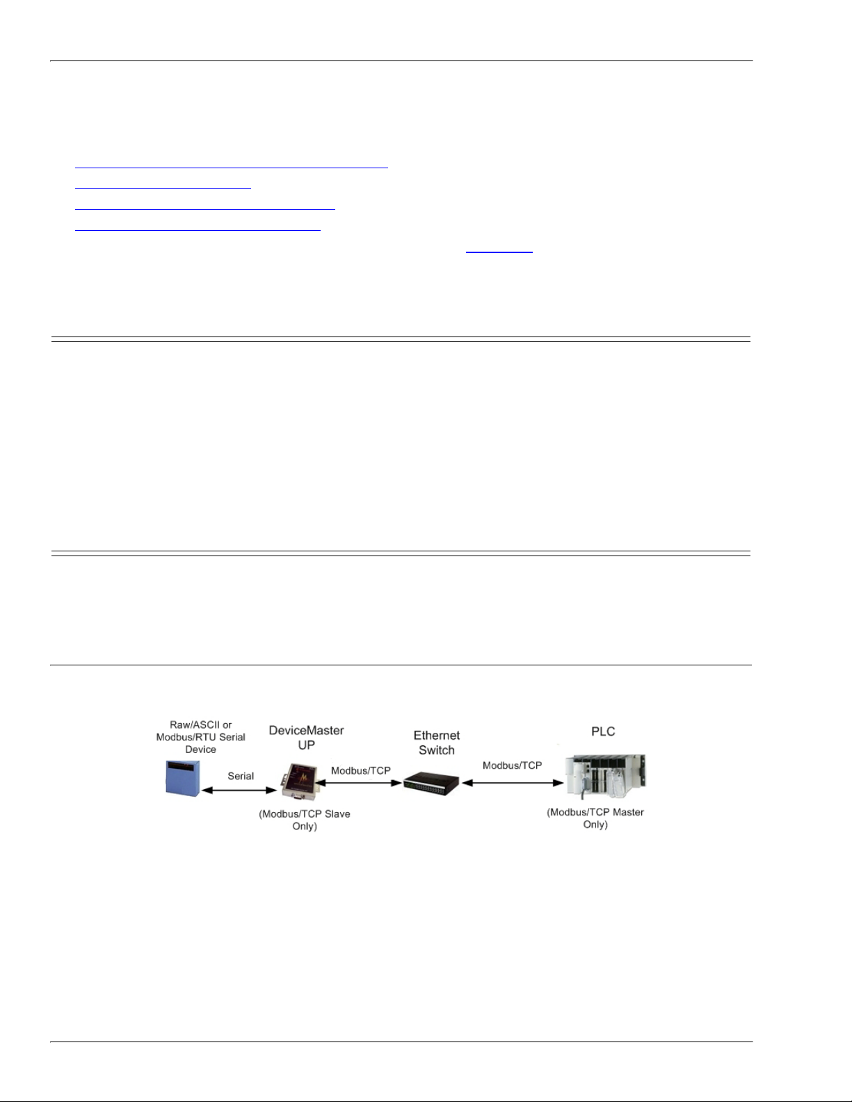
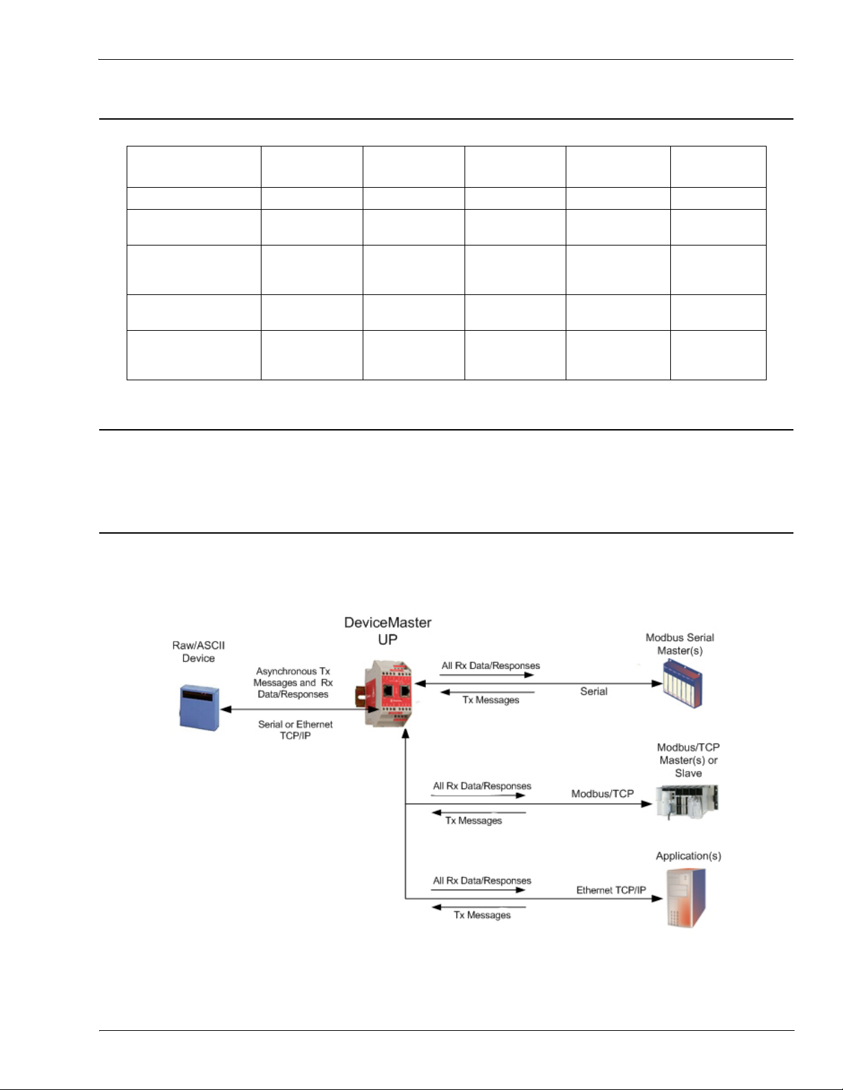
1.4.1. Traditional Modbus/TCP System Architecture (Firmware V2.x)
Modbus/TCP firmware V2.x provided a traditional Modbus/TCP slave interface to devices through a raw/
ASCII or Modbus/RTU serial interface as illustrated.
8 - Chapter 1. Introduction DeviceMaster UP Modbus/TCP User Guide: 2000447 Rev. I
Page 9
Enhanced Modbus/TCP System Architecture (Firmware 3.x)
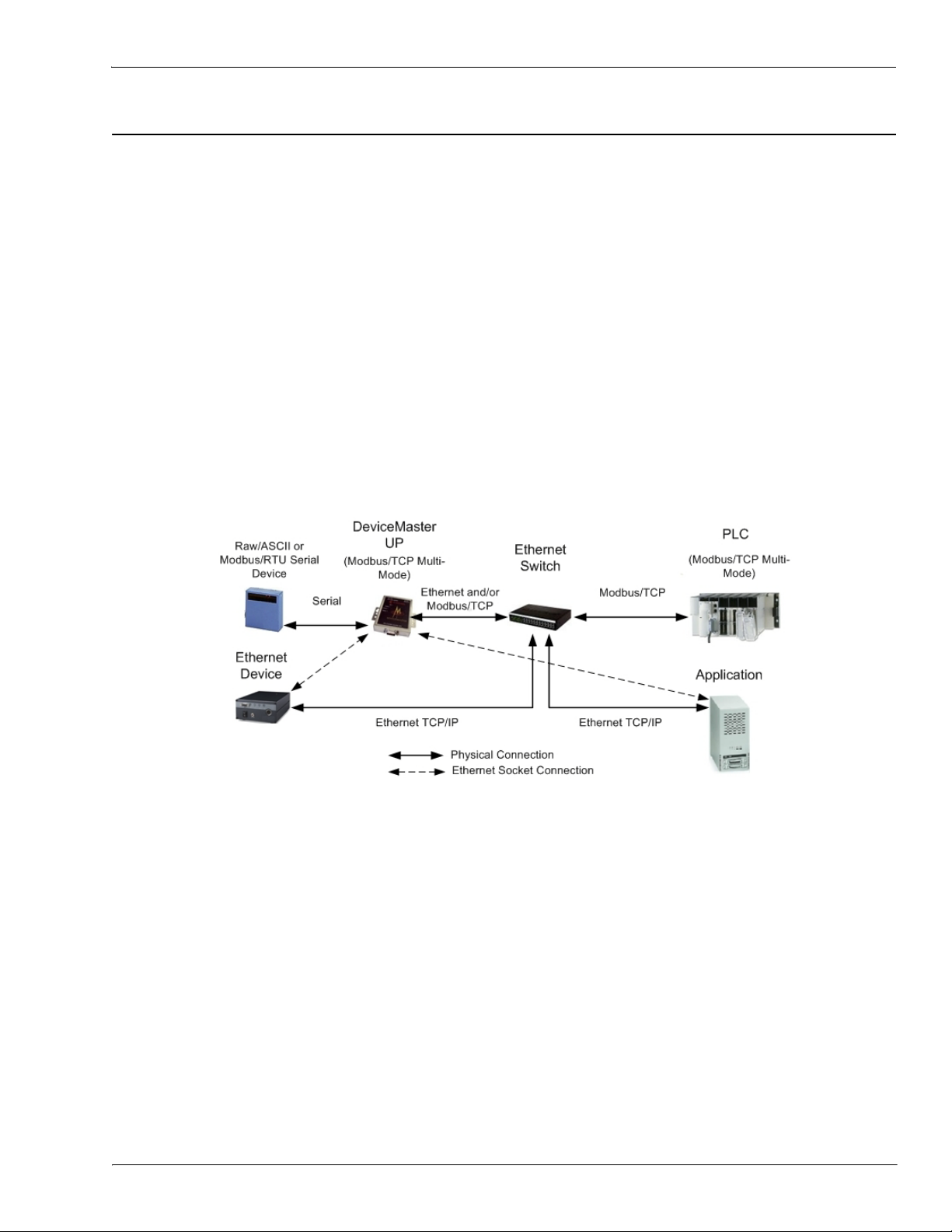
1.4.2. Enhanced Modbus/TCP System Architecture (Firmware 3.x)
Using the Modbus/TCP firmware V3.x doubles the capacity of the DeviceMaster UP by providing a raw/ASCII
interface to both serial and Ethernet TCP/IP devices. At the same time, the DeviceMaster UP continues to
provide a traditional Modbus/TCP to Modbus/RTU interface for Modbus/RTU slave devices.
• Improved PLC interfaces:
- Transfer of large received serial device packets up to 1024 bytes in Master Receive mode.
- Transfer of large received Ethernet device packets up to 2048 bytes in Master Receive mode.
- Throttling of received data to the PLC in the Master Receive mode.
- Ensures data received by the PLC is not overwritten before it can be processed.
- Disabling of non-filtered receive queue, ensures the PLC will only receive the latest received serial/
Ethernet device data.
• New embedded web pages
- PLC Interface Diagnostics page provides statistics and error messages to monitor and help diagnose
PLC interface problems.
- Serial/Ethernet Device Communication Statistics page is a comprehensive statistics page for all serial
and Ethernet device interfaces. Includes packet, byte, and error counts to the PLC(s) and
application(s) as well as comprehensive filtering statistics.
- Ethernet Device Interface Configuration page provides a user interface to the Ethernet device
interface configuration.
For example:
• The DeviceMaster UP 1-port provides Modbus/TCP support for one raw/ASCII or Modbus/RTU serial
device and one raw/ASCII Ethernet device for a total of two devices.
• The DeviceMaster UP 2-port provides Modbus/TCP support for two raw/ASCII or Modbus/RTU serial
device and two raw/ASCII Ethernet device for a total of four devices.
• The DeviceMaster UP 4-port provides Modbus/TCP support for four raw/ASCII or Modbus/RTU serial
devices and four raw/ASCII Ethernet devices for a total of eight devices.
Modbus/TCP firmware 3.x provides an application interface for both serial and Ethernet raw/ASCII devices.
You can connect any application, such as a configuration, database, or control application, via the application
socket port to raw/ASCII serial and/or Ethernet devices while the device(s) are attached to the PLC via
Modbus/TCP.
DeviceMaster UP Modbus/TCP User Guide: 2000447 Rev. I Chapter 1. Introduction - 9
Page 10

Advanced Modbus System Architecture (Firmware 5.x)
DeviceMaster UP
1.4.3. Advanced Modbus System Architecture (Firmware 5.x)
Using the Modbus/TCP V5.x firmware provides greatly enhances connectivity options. New options include:
• New Modbus support:
- Modbus/ASCII serial slave device support.
- Modbus/RTU and Modbus/ASCII serial master support. Modbus/RTU and Modbus/ASCII masters
can now connect to Modbus/RTU serial slaves, Modbus/ASCII serial slaves, and both serial and
Ethernet TCP/IP raw/ASCII devices.
• New raw/ASCII functionality:
- Selectable Message Transfer mode
- Data-Stream - Transmit all message to devices immediately. Return all receive data/responses to all
PLC and Application Ethernet TCP/IP connections.
- Command/Response - Transmit messages one command at a time and wait for response(s). Return all
response(s) to command sender only.
This version of the firmware allows up to six Application Ethernet TCP/IP connections for each serial or
socket port configuration. (Device Ethernet TCP/IP configurations still only allow one connection per device.)
10 - Chapter 1. Introduction DeviceMaster UP Modbus/TCP User Guide: 2000447 Rev. I
Page 11

Modbus/TCP Multi-Mode Connectivity
1.4.4. Modbus/TCP Multi-Mode Connectivity
The Modbus/TCP firmware 5.x supports the following Modbus/TCP communication modes:
• PLC Master/DeviceMaster UP Slave Mode
• PLC Slave/DeviceMaster UP Master Mode
• Dual Master (Virtual Peer-to-Peer) - Write Mode
• Dual Master (Virtual Peer-to-Peer) - Read Mode (Dual Polling)
• Filtering and Data Extraction Functionality (Patent Pending)
1.4.4.1. PLC Master/DeviceMaster UP Slave Mode
PLC Master/DeviceMaster
UP Slave mode:
• Standard Modbus
master to slave device
method of
communication. All
read and write
messages are initiated
by the Modbus master.
•Raw/ASCII, Modbus/
RTU slave, and
Modbus/ASCII slave
devices are supported in
this mode.
• For raw/ASCII mode, the Receive Transfer mode and Transmit Transfer mode are both set to Slave (In
Modbus/RTU-to-Slaves and Modbus/ASCII-to-Slaves mode, the DeviceMaster UP port only operates in
To-Slave mode.
on Page 11
on Page 11
on Page 12
on Page 12
on Page 13
1.4.4.2. PLC Slave/DeviceMaster UP Master Mode
PLC slave/DeviceMaster UP
master mode:
• The DeviceMaster UP
initiates all read and
write messages.
• The DeviceMaster UP
writes received serial
and/or Ethernet device
data directly into PLC
memory with minimal
latency.
• The DeviceMaster UP
polls the PLC for transmit data for serial and/or Ethernet devices.
• PLC programs can be simplified to eliminate both polling for received data and sending of write messages
to transmit data.
• Only raw/ASCII devices are supported in this mode.
• The DeviceMaster UP Receive Transfer mode and Transmit Transfer mode are both set to Master.
DeviceMaster UP Modbus/TCP User Guide: 2000447 Rev. I Chapter 1. Introduction - 11
Page 12
Dual Master (Virtual Peer-to-Peer) - Write Mode
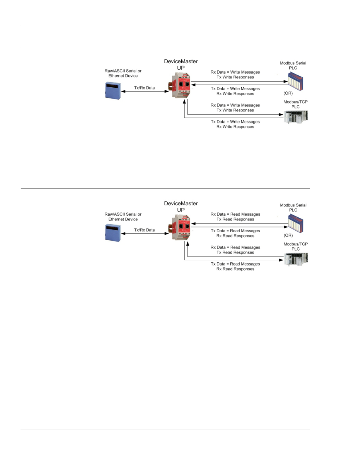
1.4.4.3. Dual Master (Virtual Peer-to-Peer) - Write Mode
Dual master (virtual peer-topeer) - write mode:
• The DeviceMaster UP
and PLC initiate only
write messages to each
other.
• The DeviceMaster UP
writes received serial
and/or Ethernet device
data directly into PLC
memory with minimal
latency.
• The PLC can write to
serial and/or Ethernet devices through the DeviceMaster UP with minimal latency.
• This mode provides the lowest possible Ethernet bandwidth usage and most efficient usage of PLC and
DeviceMaster UP processing power.
• Only raw/ASCII devices are supported in this mode.
•The DeviceMaster UP Receive Transfer mode is set to Master and Transmit Transfer mode is set to Slave.
1.4.4.4. Dual Master (Virtual Peer-to-Peer) - Read Mode (Dual Polling)
Dual master (virtual peer-topeer) - read mode (dual
polling):
• This is provided for
programmers who
strongly prefer polling.
• The DeviceMaster UP
and PLC initiate only
read messages to each
other.
• The PLC will poll for
received serial and/or
Ethernet device data.
• The DeviceMaster UP polls for transmit data to serial and/or Ethernet devices.
• This mode requires the highest possible Ethernet bandwidth usage and provides the least efficient usage
of PLC and DeviceMaster UP processing power.
• Only raw/ASCII devices are supported in this mode.
• The DeviceMaster UP Receive Transfer mode is set to Slave and Transmit Transfer mode is set to Master.
12 - Chapter 1. Introduction DeviceMaster UP Modbus/TCP User Guide: 2000447 Rev. I
Page 13
Filtering and Data Extraction Functionality (Patent Pending)
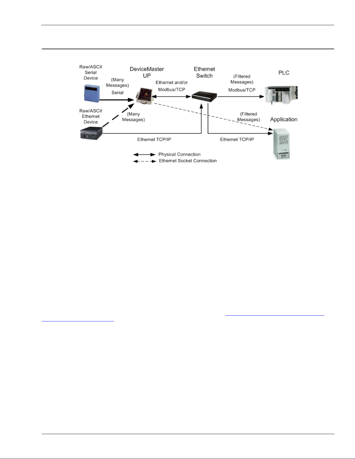
1.4.4.5. Filtering and Data Extraction Functionality (Patent Pending)
The DeviceMaster UP provides the following filtering and data extraction functionality.
•Filtering:
- String Filtering of up to 128 bytes of raw/ASCII data to both the PLC and/or application.
- RFID filtering of EPCglobal formatted RFID tag data to both the PLC and/or application.
- Barcode filtering of all UPC/EAN formatted barcodes data to both the PLC and/or application.
- Simplifies PLC and application programming tasks.
• Data Extraction:
- RFID data extraction extracts all parameters, such as company code, product code, and serial
numbers, from any or all of the 43 EPCglobal tag formats. It then transfers the data to the PLC and/
or application in a consistent and simple format.
- Barcode data extraction extracts the company, product, and numbering codes from UPC/EAN
formatted barcodes. It then transfers the data to the PLC and/or application in a consistent and
simple format.
- Simplifies PLC and application programming tasks.
• Environment specific support:
- Support for multiple RFID reader tag formats.
- RFID antenna grouping.
- Aging of filtered string/RFID/barcode entries.
- Discarding of unrecognized RFID and barcode messages.
For detailed information about filtering and data extraction, see the DeviceMaster UP Filtering and Data
Extraction Reference Guide.
DeviceMaster UP Modbus/TCP User Guide: 2000447 Rev. I Chapter 1. Introduction - 13
Page 14

Definitions and Terms
1.5. Definitions and Terms
This section describes the Modbus/TCP definitions and terms included in the Modbus/TCP interface and
supported by the DeviceMaster UP.
1.5.1. Data Type Definitions
The following list defines the available data types.
Data Type Definition
BYTE Bit String (8-bits)
DINT Signed Double Integer (32-bits)
DWORD Bit String (32-bits)
INT Signed Integer (16-bits)
STRING Character String (1-byte per character)
UDINT Unsigned Double Integer (32-bits)
USINT Unsigned Short Integer (8-bits)
WORD Unsigned Integer (16-bits)
1.5.2. Glossary
The following list defines terms associated with Modbus/TCP.
Term Definition
Alias Device ID
Device ID
Ethernet Device A device that communicates through an Ethernet TCP/IP connection.
Master Device
Modbus
Modbus Serial The Modbus protocol over a serial connection.
Modbus/ASCII
Modbus/RTU Modbus Serial in binary format.
Modbus/TCP
Raw Serial
Device
Slave Address The address of the slave device. This term is identical to Unit Identifier and Device ID.
Slave Device A device that only responds to Modbus messages.
Socket Port The Ethernet socket port that is used to communicate to an Ethernet device.
The device ID that the original received ID is changed to when an Alias Device ID is
configured.
The address of the slave device and the term is identical to Unit Identifier and Slave
Address.
A device that transmits Modbus/TCP messages to slave devices and receives the
corresponding responses.
An application layer messaging protocol that provides client/server communications
between devices connected on different types of buses.
Modbus Serial in ASCII format. This form of Modbus communication requires two
characters for each byte.
The Modbus protocol over an Ethernet TCP/IP connection. Also known as Modbus over
Ethernet.
A common serial device that communicates over serial ports through plain byte or ASCII
data messages.
14 - Chapter 1. Introduction DeviceMaster UP Modbus/TCP User Guide: 2000447 Rev. I
Page 15

Locating Updated Software and Documents
Term Definition (Continued)
Unit Identifier The address of the slave device and the term is identical to Device ID and Slave Address.
1.6. Locating Updated Software and Documents
You can access the firmware software assembly, PortVision DX, and the DeviceMaster UP documentation
from the CD shipped with the DeviceMaster UP or you can download the latest files from:
ftp://ftp.comtrol.com/html/up_modbus_tcp_main.htm
1.7. Modbus/TCP Application Setup
Before you can configure the Modbus/TCP firmware on the DeviceMaster UP, you must have previously
performed the following steps:
• Install the hardware
• Install PortVision DX
• If necessary, upload the Modbus/TCP firmware using PortVision DX
Note: Models that have Modbus/TCP loaded on the DeviceMaster UP are identified in PortVision DX and
the DeviceMaster UP is labeled accordingly.
• Configure the DeviceMaster UP IP address using PortVision DX
Note: If necessary, refer to the DeviceMaster UP Hardware Installation and Configuration Guide
above procedures.
Use the following steps to complete the DeviceMaster UP configuration for Modbus/TCP.
1. Program the Modbus/TCP PLC (refer to the information in Programming Interface
2. Configure the DeviceMaster UP serial and Ethernet device interface settings using the Modbus/TCP
Interface Configuration Quick Start. You can use Embedded Configuration Pages on Page 33) as a
reference if you need additional information about fields on the web pages.
3. Connect your serial device or devices and make sure all Ethernet devices are attached to the same
Ethernet subnet. If necessary, refer to the DeviceMaster UP Hardware Installation and Configuration
Guide.
on Page 17).
for the
DeviceMaster UP Modbus/TCP User Guide: 2000447 Rev. I Chapter 1. Introduction - 15
Page 16

Modbus/TCP Application Setup
16 - Chapter 1. Introduction DeviceMaster UP Modbus/TCP User Guide: 2000447 Rev. I
Page 17

Chapter 2. Programming Interface
2.1. Overview
The DeviceMaster UP provides highly flexible Modbus connectivity.
• Modbus masters supported include Modbus/TCP and Modbus/RTU and Modbus/ASCII serial masters.
• Both serial Modbus/RTU and Modbus/ASCII slave devices are supported.
• All Modbus masters can communicate with all Modbus slave devices.
• The Modbus/RTU and Modbus/ASCII Protocol Interface is defined in (2.4.
ASCII To-Slaves Protocol Interface on Page 29).
The DeviceMaster UP provides highly advanced raw/ASCII device functionality:
• Both serial and Ethernet TCP/IP devices are supported.
• Modbus interfaces include Modbus/TCP masters, Modbus/TCP slaves, and both Modbus/RTU and
Modbus/ASCII serial masters.
• Up to six Ethernet TCP/IP Application connections per serial or Ethernet TCP/IP device.
• The raw/ASCII interface is defined in (2.2.
You must configure the DeviceMaster UP through its embedded web pages defined in Chapter 3.
Configuration Pages on Page 33.
The DeviceMaster UP uses normal Modbus addressing conventions and provides receive, transmit, and
statistical data.
Appendix A.
examples provided with the DeviceMaster UP. It describes how to configure the DeviceMaster UP for raw
serial data and start running the example programs using the embedded web pages and the example PLC
program code.
Note: While the Concept PLC example programs directly apply only to the Schneider Electric Momentum,
Programming the PLC via Concept on Page 85 describes the Concept™ PLC programming
Quantum, and Compact PLCs, they can be used as a guide for programming other PLCs.
Raw Data Interface on Page 19).
Modbus/RTU and Modbus/
Embedded
2.1.1. Modbus Master Requirements
Modbus Masters (Modbus/TCP, Modbus/RTU serial, and Modbus/ASCII) must meet these requirements:
• The Modbus Master must support the corresponding protocol.
• For raw/ASCII data, the Modbus Master must support the Read Holding Registers and Write Multiple
Registers commands or, alternatively, the Read/Write Multiple Registers command.
• The Modbus Master must be able to write enough data in one message to handle the maximum sized
messages required for the serial or Ethernet device.
DeviceMaster UP Modbus/TCP User Guide: 2000447 Rev. I Chapter 2. Programming Interface - 17
Page 18

What is Modbus/RTU?
2.1.2. What is Modbus/RTU?
Modbus/RTU is native Modbus in hexadecimal format. These are the base Modbus messages that contain
simple read and write requests. The format is as follows:
Where:
• The terms Master or Client are used to identify the sender of the message.
• The terms Slave or Server are used to identify the devices responding to the message.
Modbus/RTU is used primarily for:
• Serial port connectivity. RS-485 is the most common serial mode, but RS-232 and RS-422 are also widely
used. Commonly used by both Master and Slave devices.
• Ethernet TCP/IP socket connections. This is not the same as Modbus/TCP (please see section on Modbus/
TCP), but does provide a very simple method of interfacing to remote devices. It is used by many
applications and some OPC servers.
Note: This communication method typically is not supported by PLCs.
2.1.3. What is Modbus/ASCII?
Modbus/ASCII is native Modbus in ASCII format. This protocol is used primarily by legacy devices and is no
longer supported as widely as Modbus/RTU.
Like Modbus/RTU, Modbus/ASCII contains the base Modbus messages that contain simple read and write
requests. The differences between Modbus/ASCII and Modbus/RTU are:
1. The message data is sent in ASCII format, so the message length is twice as long. It requires two ASCII
characters for each byte of data.
2. An 8 bit LRC is attached to verify the message instead of a 16 bit CRC. The LRC is also transmitted in
ASCII format.
3. There are defined starting and ending characters to determine a Modbus/ASCII messages.
The format is as follows:
Where:
• The terms Master or Client are used to identify the sender of the message.
• The terms Slave or Server are used to identify the devices responding to the message.
Modbus/ASCII is used primarily for:
• Serial port connectivity. RS-485 is the most common serial mode, but RS-232 and RS-422 are also used.
Used primarily by legacy Slave devices.
• Ethernet TCP/IP socket connections. This is not the same as Modbus/TCP (please see section on Modbus/
TCP), but does provide a very simple method of interfacing to remote devices. It is used by some
applications and some OPC servers.
Note: This communication method typically is not supported by PLCs.
18 - Chapter 2. Programming Interface DeviceMaster UP Modbus/TCP User Guide: 2000447 Rev. I
Page 19
What is Modbus/TCP?
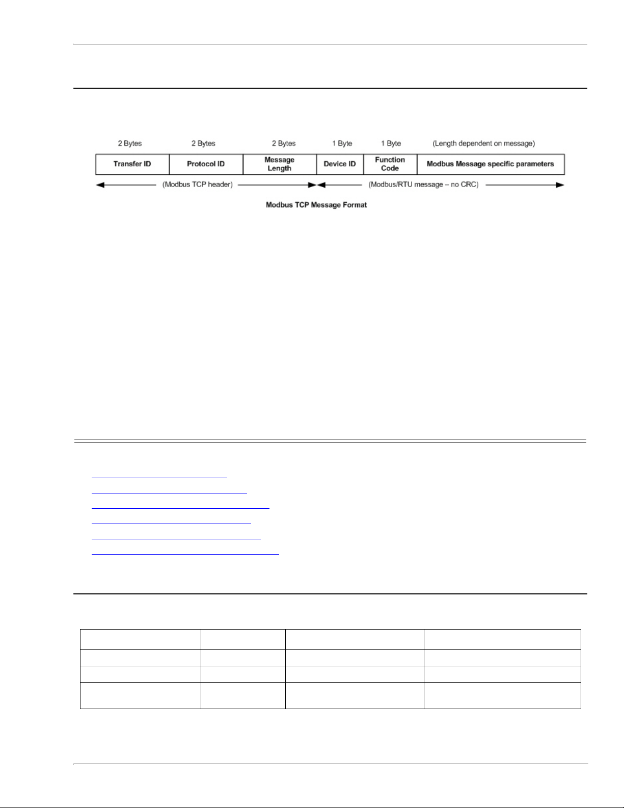
2.1.4. What is Modbus/TCP?
Modbus/TCP is an Ethernet network based protocol that contains a Modbus/RTU message, with the exception
of the 2 byte CRC. The Modbus/TCP message contains a header with information designed to provide message
identification and routing information. The format is as follows:
Where:
• The terms Master or Client are used to identify the sender of the message.
• The terms Slave or Server are used to identify the devices responding to the message.
• Modbus TCP messages are typically sent to and received on a defined Ethernet TCP/IP socket of 502.
• Modbus TCP implementations provide more capability, but also require more processing than simpler
Modbus/RTU implementations.
Modbus TCP is used for connecting advanced Ethernet based devices, such as PLCs, HMIs, SCADA Systems,
and most OPC Servers to:
• Other Ethernet devices supporting Modbus TCP.
• Serial Modbus/RTU and/or Modbus/ASCII devices through gateways (such as the DeviceMaster UP
running the Modbus/TCP or Modbus Router applications).
• Serial or Ethernet TCP/IP raw/ASCII devices (barcode scanners, printers, RFID readers, visions systems,
etc) through a gateway (such as the DeviceMaster UP running the Modbus/TCP application).
2.2. Raw Data Interface
This subsection contains the following topics:
• Supported Modbus Messages
• Serial Port Raw/ASCII Interface
• Ethernet Device Raw/ASCII Interface
• Receive Data Message
• Transmit Data Message
• Sequence Number Messages
(Raw Data) on Page 23
2.2.1. Supported Modbus Messages
DeviceMaster UP supports the following Modbus messages over Modbus/TCP for raw data transfer.
Message Type Function Code Maximum Message Size Maximum Serial Packet Size
Read Holding Registers 3 250 BYTEs (125 WORDs) 246 BYTEs (123 WORDs)
Write Multiple Registers 16 (10 hex) 240 BYTEs (120 WORDs) 236 BYTEs (118 WORDs)
Read/Write Multiple
Registers
on Page 19
on Page 20
on Page 21
(Raw Data) on Page 25
(Raw Data) on Page 27
23 (17 hex) 236 BYTEs (118 WORDs) 232 BYTEs (116 WORDs)
Note: Your PLC programming software may not allow maximum size serial packets.
DeviceMaster UP Modbus/TCP User Guide: 2000447 Rev. I Chapter 2. Programming Interface - 19
Page 20

Serial Port Raw/ASCII Interface
2.2.2. Serial Port Raw/ASCII Interface
Serial Port
Raw/ASCII
Addressing
Unit ID 255 (FF hex) 255 (FF hex) 255 (FF hex) 255 (FF hex) N/A
Receive Data
Address
Receive Data
Sequence
Number Address
Transmit Data
Address
Transmit Data
Sequence
Number Address
Statistics
Address
Serial Port 1 Serial Port 2 Serial Port 3 Serial Port 4 Access Rule
1000 (Base 0)
1001 (Base 1)
1256 (Base 0
1257 (Base 1)
1300 (Base 0)
1301 (Base 1)
1556 (Base 0)
1557 (Base 1)
1600 (Base 0)
1601 (Base 1)
2000 (Base 0)
2001 (Base 1)
2256 (Base 0
2257 (Base 1)
2300 (Base 0)
2301 (Base 1)
2556 (Base 0)
2557 (Base 1)
2600 (Base 0)
2601 (Base 1)
3000 (Base 0)
3001 (Base 1)
3256 (Base 0
3257 (Base 1)
3300 (Base 0)
3301 (Base 1)
3556 (Base 0)
3557 (Base 1)
3600 (Base 0)
3601 (Base 1)
4000 (Base 0)
4001 (Base 1)
4256 (Base 0
4257 (Base 1)
4300 (Base 0)
4301 (Base 1)
4556 (Base 0)
4557 (Base 1)
4600 (Base 0)
4601 (Base 1)
Read Only
Read/Write
Read/Write
Read/Write
Read/Write
20 - Chapter 2. Programming Interface DeviceMaster UP Modbus/TCP User Guide: 2000447 Rev. I
Page 21
2.2.3. Ethernet Device Raw/ASCII Interface
Ethernet Device Raw/ASCII Interface
Socket Port Raw
Data Addressing
Socket Port 1 Socket Port 2 Socket Port 3 Socket Port 4 Access Rule
Unit ID 254 (FE hex) 254 (FE hex) 254 (FE hex) 254 (FE hex) N/A
Receive Data
Address
Receive Data
Sequence Number
Address
Transmit Data
Address
Transmit Data
Sequence Number
Address
1000 (Base 0)
1001 (Base 1)
1256 (Base 0
1257 (Base 1)
1300 (Base 0)
1301 (Base 1)
1556 (Base 0)
1557 (Base 1)
2000 (Base 0)
2001 (Base 1)
2256 (Base 0
2257 (Base 1)
2300 (Base 0)
2301 (Base 1)
2556 (Base 0)
2557 (Base 1)
3000 (Base 0)
3001 (Base 1)
3256 (Base 0
3257 (Base 1)
3300 (Base 0)
3301 (Base 1)
3556 (Base 0)
3557 (Base 1)
4000 (Base 0)
4001 (Base 1)
4256 (Base 0
4257 (Base 1)
4300 (Base 0)
4301 (Base 1)
4556 (Base 0)
4557 (Base 1)
Read Only
Read/Write
Read/Write
Read/Write
2.2.4. Raw/ASCII Transfer Modes
The DeviceMaster UP supports two different raw/ASCII message transfer modes. The default Data-Stream
mode is the traditional transfer mode that asynchronously transmits messages and returns received data/
responses. The Command/Response mode provides a synchronous transfer mode for sending and returning
responses.
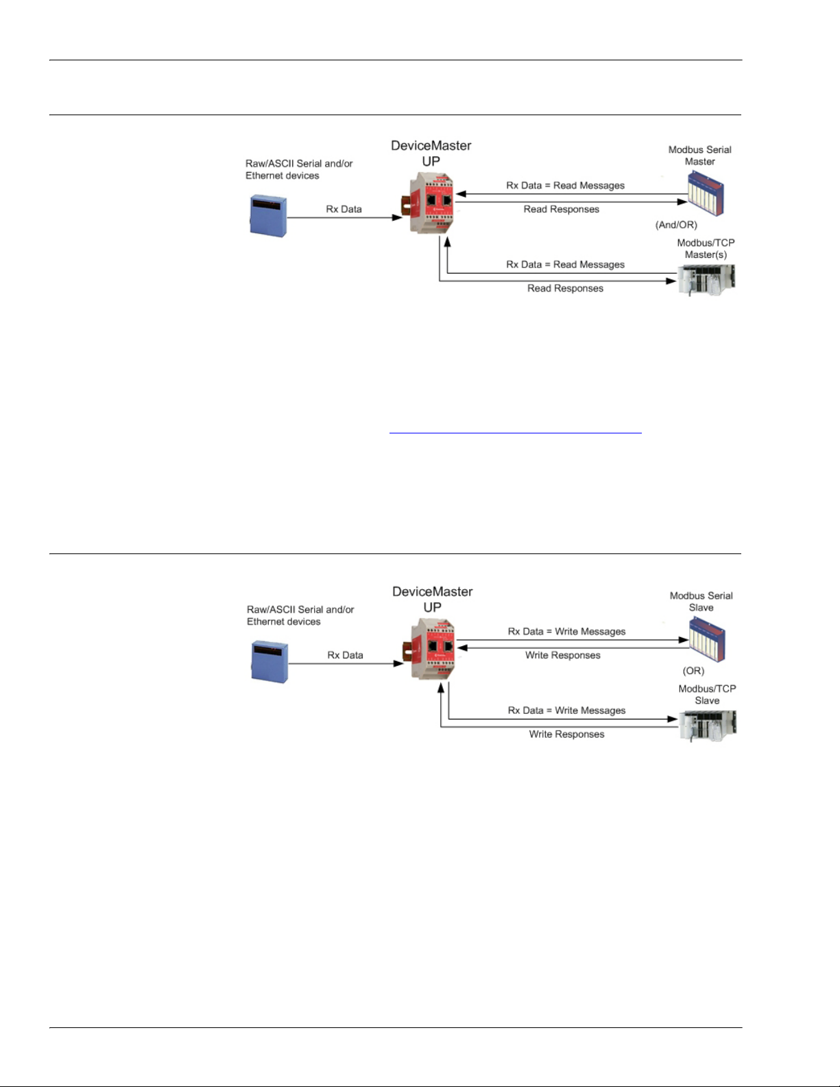
2.2.4.1. Data-Stream Mode
The Data-Stream transfer mode is the default transfer mode that asynchronously transmits messages from
all Modbus and Application interfaces and returns received data/responses to all Modbus and Application
interfaces. This mode is typically used in installations that utilize only one controller and for receive-only
devices such as barcode scanners, RFID readers, weigh scales, and position encoders.
DeviceMaster UP Modbus/TCP User Guide: 2000447 Rev. I Chapter 2. Programming Interface - 21
Page 22
Command/Response Mode
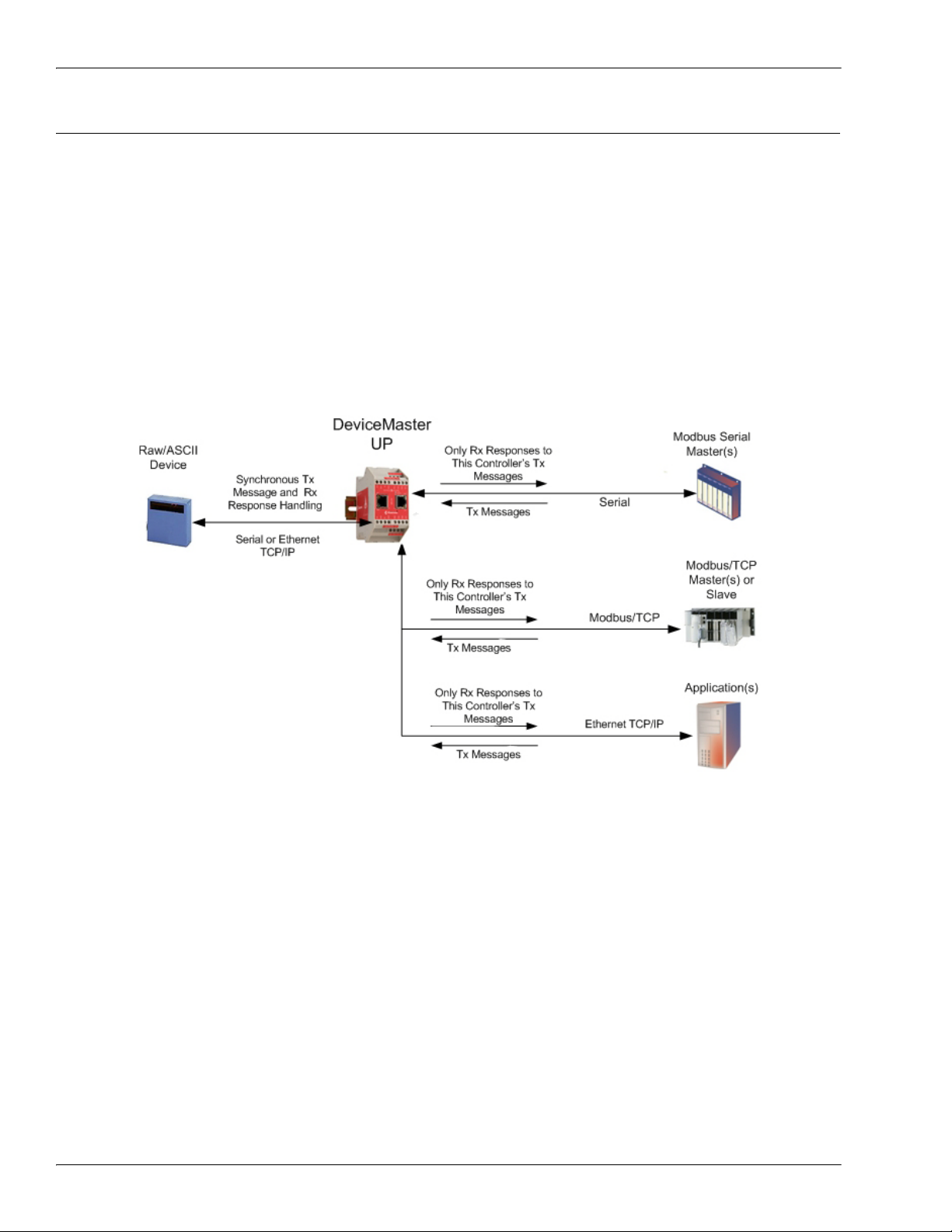
2.2.4.2. Command/Response Mode
The Command/Response mode provides the following functionality:
• A synchronous transfer mode for sending and returning responses from all Modbus and Application
Ethernet TCP/IP interfaces to serial and Ethernet TCP/IP devices.
• Only one command message is transmitted at a time. Command messages are queued if a command
message is active.
• Responses are routed only to the message sender.
• Responses are timed out and old responses, (ones not requested within a certain time frame), destined for
the Modbus interface are discarded.
• The expected response count is configurable. While this is typically one, some devices may return multiple
responses per message.
The Command/Response transfer mode is typically required in installations that require multiple controllers
sending raw/ASCII messages with expected responses, and it is desired that each controller only receive its
own responses.
22 - Chapter 2. Programming Interface DeviceMaster UP Modbus/TCP User Guide: 2000447 Rev. I
Page 23

Receive Data Message (Raw Data)
2.2.5. Receive Data Message (Raw Data)
The following topics are discussed:
• Format
• Communication Methodology (Receive Raw Data in Slave Mode)
• Communication Methodology (Receive Data Master Mode)
2.2.5.1. Format
The Receive Data message for raw data contains a simple protocol including a sequence number, length and
serial data fields. The Modbus standard requires a WORD format.
The following table displays the format of the Receive Data message.
on Page 23
on Page 24
on Page 24
Name Data Type Data Value(s) Access Rule
Receive (to PLC) message data.
Structure of:
Produced data sequence
Data length (in bytes)
Data array
WORD
WORD
Array of WORD
0-65535 (FFFF hex)
0-246 (slave Rx mode)
1-1024 (serial Rx master)
1-2048 (Ethernet Rx master)
0-65535
Read only
Receive messages have the following characteristics:
• It returns all data in WORDs.
• The DeviceMaster UP increments the sequence number when it returns new data.
• The message received from the PLC determines the actual length of the Modbus message returned to the
PLC. (This is often greater than the length of the actual number of valid bytes in the Receive Data
Message.)
• All unused bytes in a Modbus message returned to the PLC are filled with zeroes.
• The default order of the bytes is Least Significant Byte First. However, you can select the Rx MS Byte
First option in the web page to return bytes by Most Significant Byte First. For more information, see Rx
MS Byte First under 3.3.5.
Serial Port Packet ID Settings (Raw-Data Only) on Page 39.
DeviceMaster UP Modbus/TCP User Guide: 2000447 Rev. I Chapter 2. Programming Interface - 23
Page 24
Communication Methodology (Receive Raw Data in Slave Mode)
2.2.5.2. Communication Methodology (Receive Raw Data in Slave Mode)
Raw serial and/or EtherNet
device data is returned in
the response to the Read
Holding Registers message
or, optionally, the Read/
Write Multiple Register
message. The data is
requested by accessing the
corresponding receive data
address for the desired port.
The following restrictions
apply to this method:
•The Device Index must be 255 (FF hex) for raw/ASCII serial data and 254 (FE hex) for raw/ASCII
Ethernet device data.
• The variable to receive the data on the PLC must be:
- In the 40xxxx address range. (For Modicon type PLCs.)
- An array of 16 bit words.
- Of sufficient size to contain the sequence number, length, and data field associated with the received
data structure. For more information, see the 2.2.5.
Receive Data Message (Raw Data) definition on
Page 23.
• New data will be indicated with an incremented sequence number.
The same data may be returned more than once. However, the same data packet will also return the same
sequence number.
• No data will be indicated with a length of zero.
2.2.5.3. Communication Methodology (Receive Data Master Mode)
Raw serial and/or Ethernet
device data is written to the
PLC at the configured
address.
The following restrictions
apply to this method:
•The Device Index must be
configured for the target
PLC.
• The variable to receive
the data on the PLC
must be:
- In the 40xxxx. (For Modicon type PLCs.)
- An array of 16 bit words.
- Of sufficient size to contain the sequence number, length, and data field associated with the received
data structure.
• New data will be indicated with an incremented sequence number.
24 - Chapter 2. Programming Interface DeviceMaster UP Modbus/TCP User Guide: 2000447 Rev. I
Page 25

Transmit Data Message (Raw Data)
2.2.6. Transmit Data Message (Raw Data)
The following topics are discussed:
• Format
• Communication Methodology (Transmit Raw Data Slave Mode)
• Communication Methodology (Transmit Data Master Mode)
2.2.6.1. Format
The Transmit Data message for raw data contains a simple protocol including a sequence number, length and
serial data fields. The Modbus standard requires a WORD format.
The following table displays the format of the Transmit Data message.
on Page 25
on Page 26
on Page 26
Name Data Type Data Value(s) Access Rule
Transmit (PLC to DeviceMaster UP)
message data.
Structure of:
Produced data sequence
Data length (in bytes)
Data array
WORD
WORD
Array of WORD
0-65535 (FFFF hex)
1-236 (Slave Tx Mode)
1-246 (Master Tx Mode)
0-65535
Read/Write
Transmit messages have the following characteristics:
• It transfers all data in WORDs.
•If the Disable Tx Sequence Number Check option is not selected, the sequence number must be incremented
when there is new data to transmit.
• The data length field indicates the number of valid bytes contained in the message.
• The actual length of a message received from the PLC may contain extra, unused data.
• It ignores all unused bytes in a Modbus message.
• The default order of the bytes is Least Significant Byte First. However, you can select the Tx MS Byte First
option in the web page to transmit bytes by Most Significant Byte First. For more information, see Tx MS
Byte First under 3.3.5.
Serial Port Packet ID Settings (Raw-Data Only) on Page 39.
• A request for the Transmit data returns the last transmit data message.
DeviceMaster UP Modbus/TCP User Guide: 2000447 Rev. I Chapter 2. Programming Interface - 25
Page 26

Communication Methodology (Transmit Raw Data Slave Mode)
2.2.6.2. Communication Methodology (Transmit Raw Data Slave Mode)
Raw serial and/or EtherNet
device data is sent in the
Write Multiple Registers
message or, optionally, the
Read/Write Multiple
Register message. The data
is requested by accessing
the corresponding transmit
data address for the desired
port.
The following restrictions
apply to this method:
•The Device Index must be 255 (FF hex) for raw/ASCII serial data and 254 (FE hex) for raw/ASCII
Ethernet device data.
• The variable to transmit the data on the PLC must be:
- In the 40xxxx address range. (For Modicon type PLCs.)
- An array of words.
- Of sufficient size to contain the sequence number, length, and data field associated with the transmit
data structure, typically 128 words. See 2.2.6.
Transmit Data Message (Raw Data) on Page 25 for
more information.
•If the Disable Tx Sequence Number Check option is not selected, the sequence number must be incremented
when there is new data to transmit. The same transmit data message may be sent to the DeviceMaster
UP more than once. However, the data packet will only be transmitted when a new sequence number is
received.
2.2.6.3. Communication Methodology (Transmit Data Master Mode)
Raw serial and/or Ethernet
transmit data is polled from
the PLC at the configured
address and, when the
DeviceMaster UP receives a
transmit message with an
updated sequence number,
the data is transmitted to
the serial or Ethernet
device.
• The following
restrictions apply to this
method:
•The Device Index must be configured for the target PLC.
• The variable to receive the data on the PLC must be:
- In the 40xxxx. (For Modicon type PLCs.)
- An array of 16 bit words.
- Of sufficient size to contain the sequence number, length, and data field associated with the transmit
data structure.
• The PLC will indicate new data to transmit with an incremented sequence number. (The Disable Tx
Sequence Number Check option does not apply to transmit data master mode.)
• The length will indicate the number of bytes to transmit.
• The DeviceMaster UP will expect the length parameter and data to transmit to be updated before the
transmit sequence number is incremented. Therefore, as soon as the DeviceMaster UP receives an
incremented transmit number, it will transmit the data to the serial or Ethernet device.
26 - Chapter 2. Programming Interface DeviceMaster UP Modbus/TCP User Guide: 2000447 Rev. I
Page 27

Sequence Number Messages (Raw Data)
2.2.7. Sequence Number Messages (Raw Data)
Read Holding Registers and Write Multiple Register messages can read and modify both receive and transmit
produced data sequence numbers. These are the same sequence numbers returned to the PLC in the Receive
Data Message and sent to the DeviceMaster UP in the Transmit Data message. Access to these sequence
numbers are provided primarily for initialization purposes at the start of the PLC program when you may
want to initialize the sequence numbers on the PLC, DeviceMaster UP or both.
2.3. I/O Scanner (Raw Data)
The I/O Scanner is an optional
PLC communications method
that is implemented on some
PLC programming software
such as the Concept
programming package for use
with the Schneider Electric
Modicon PLCs. The I/O
Scanner provides a rather
simple method that requires
minimal programming effort. It
automatically performs the
polling and transmitting of
data at set time intervals and typically utilizes the Read/Write multiple Registers message.
The following restrictions apply to this method:
•The Receive and Transmit mode for the serial and/or Ethernet device must both be set to Slave mode.
•The Device Index must be 255 (FF hex) for raw/ASCII serial data and 254 (FE hex) for raw/ASCII
Ethernet device data.
• The variable to receive the data on the PLC must be:
- In the 40xxxx address range. (For Modicon type PLCs.)
- An array of words.
- Of sufficient size to contain the sequence number, length, and data field associated with the received
data structure, typically 128 words. For more information, see the 2.2.5.
Data) definition on Page 23.
• New received data will be indicated with an incremented sequence number.
The same data may be returned more than once. However, the same data packet will also return the same
sequence number.
• No receive data will be indicated with a length of zero.
• The variable to transmit the data on the PLC must be:
- In the 40xxxx address range. (For Modicon PLCs.)
- An array of words.
- Of sufficient size to contain the sequence number, length, and data field associated with the transmit
data structure, typically 128 words. See 2.2.6.
more information.
•If the Disable Tx Sequence Number Check option is not selected, the sequence number must be incremented
when there is new data to transmit.
The same transmit data message may be sent to the DeviceMaster UP more than once. However, the data
packet will only be transmitted when a new sequence number is received.
• The DeviceMaster UP should be reset before starting a PLC program using the I/O Scanner due to PLC
program execution scheduling. If the DeviceMaster UP is not reset, the sequence numbers may be out of
sync. This may result in receiving outdated serial data as well as an unexpected transmission of serial
data. A Transmit Unexpected Sequence Number error may also occur.
Transmit Data Message (Raw Data) on Page 25 for
Receive Data Message (Raw
DeviceMaster UP Modbus/TCP User Guide: 2000447 Rev. I Chapter 2. Programming Interface - 27
Page 28
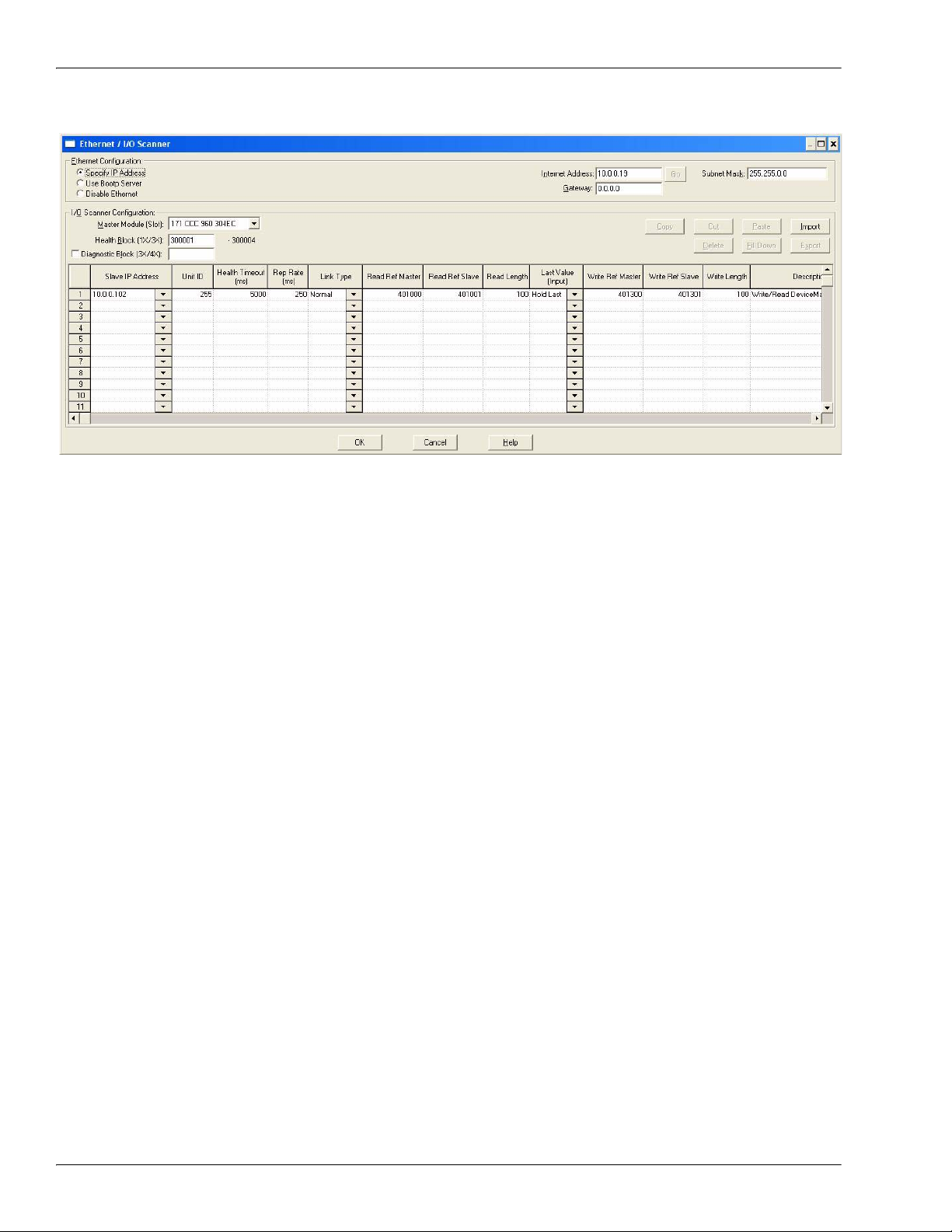
I/O Scanner (Raw Data)
The following depicts a typical I/O Scanner screen.
28 - Chapter 2. Programming Interface DeviceMaster UP Modbus/TCP User Guide: 2000447 Rev. I
Page 29
Modbus/RTU and Modbus/ASCII To-Slaves Protocol Interface
2.4. Modbus/RTU and Modbus/ASCII To-Slaves Protocol Interface
The DeviceMaster UP provides access to serial Modbus/RTU and Modbus/ASCII slave devices via Modbus/
TCP, serial Modbus/RTU masters, and serial Modbus/ASCII masters. Modbus master messages are
translated to Modbus/RTU or Modbus/ASCII messages, devices are automatically located, and appropriate
Modbus responses are returned to the Modbus masters.
2.4.1. Communication Methodology
The DeviceMaster UP translates Modbus master messages into Modbus/RTU or Modbus/ASCII messages and
forwards them to slave devices attached to the Modbus/RTU or Modbus/ASCII slave serial ports. Each
Modbus message is transmitted and a response is expected. The DeviceMaster UP times out the Modbus/RTU
or Modbus/ASCII messages if there is no response returned within the configured timeout period.
The following diagram displays the Modbus message transfer.
The following apply to Modbus slaves serial ports.
• All valid Modbus master messages are translated to Modbus slave messages for serial port transmission.
• Modbus slave devices are automatically located on a DeviceMaster UP 2-port or 4-port.
• Messages are timed out if no response is returned within the configured timeout period.
• Appropriate Modbus responses are returned to the Modbus master.
• Broadcast Modbus messages, those with a unit identifier of zero, are transmitted out all Modbus slave
serial ports on the DeviceMaster UP.
The following restrictions apply to the Modbus slave interface:
• The DeviceMaster UP serves as a slave Modbus/TCP device, a master on Modbus To-Slaves serial ports,
and a slave on Modbus To-master serial ports.
• All Modbus slave devices attached to a DeviceMaster UP gateway (1, 2, or 4-port) must have unique Unit
Identifiers. Valid Unit Identifiers are 1 to 247 and the Broadcast Identifier is zero.
To communicate to Modbus slave device(s) through a DeviceMaster UP, perform the following steps.
1. Using the embedded web page, select the appropriate Port.
2. Under Serial Configuration, configure the serial port parameters such as the Mode, Baud rate, Data Bits,
and so forth.
3. Under General Protocol Settings, set the Select Serial Port Protocol to Modbus slave.
4. Under Modbus Slave Protocol Settings, set the Device Response Timeout to the desired value.
Note: 2- and 4-Port only: set the Lost Device Search Enable setting. For a discussion on this setting, see
2.4.2.
Modbus Slave Device Search Methodology on Page 30.
DeviceMaster UP Modbus/TCP User Guide: 2000447 Rev. I Chapter 2. Programming Interface - 29
Page 30

Modbus Slave Device Search Methodology
5. In the PLC program, address messages to the Modbus slave device using the IP Address of the
DeviceMaster UP and the Unit Identifier of the slave device(s).
2.4.2. Modbus Slave Device Search Methodology
Locating a Modbus slave device on a DeviceMaster UP 1-port is relatively simple. Either the Modbus slave
device is connected to the port or it is not. However, if more than one port is configured for Modbus slave on a
DeviceMaster UP 2- or 4-port, the device must be found. The following is an explanation of how the search
algorithm works on a DeviceMaster UP 2- or 4-port.
Locating a Modbus slave device after a reboot or port reset:
When the DeviceMaster UP receives a message for a Modbus slave device for the first time since reboot or
port initialization, it will transmit the Modbus slave message out all Modbus slave serial ports and wait for a
response to be returned. Once the response is returned, the device port is known and all messages sent to the
device will be routed through the serial port.
Lost Devices:
Lost devices, or devices that time out, are a special case. The DeviceMaster UP provides two methods for
handling lost devices via the Lost Device Search Enable option on the web page.
• Disabling this option on a Modbus slave port:
- Prevents the DeviceMaster UP from searching for a lost device on other Modbus slave ports.
- Prevents lost devices known to have been on other ports from being searched for on this port.
Note: This is the recommended setting whenever it is desired to prevent timeout delays on other Modbus
slave ports in the event that a device times out.
• Enabling this option on a Modbus slave port:
- Allows the DeviceMaster UP to search for lost devices on all Modbus slave ports with the Lost Device
Search Enable option turned on.
Note: This can be useful for locating devices if a device has been moved onto another port by moving
the serial cable or, perhaps, by moving the device onto a different Modbus slave serial loop.
- This will cause timeout delays on all Modbus slave ports with the Device Search Enable option turned
on until the device is found.
30 - Chapter 2. Programming Interface DeviceMaster UP Modbus/TCP User Guide: 2000447 Rev. I
Page 31

Retrieve Statistics Message
2.5. Retrieve Statistics Message
The data returned from the Retrieve Statistics message contains various counters. The Retrieve Statistics
message formats the data into 32-bit integers and returns data in an array of WORDs. The first WORD
contains the most significant word and the second WORD contains the least significant word.
DeviceMaster UP Addressing for the
Statistics Modbus/TCP Messages
Serial Port 1Serial Port 2Serial Port 3Serial Port 4Access
Rule
Unit ID 255 (FF hex) 255 (FF hex) 255 (FF hex) 255 (FF hex) N/A
Statistics Address 1600 2600 3600 4600 Read Only
Note: Some Modicon PLC programming software, such as Concept, requires one to be added to the address
offset. This is because their address range begins at 40001, while the address range on the DeviceMaster
UP begins at zero.
The following table displays the format of the Retrieve Statistics message.
Index Name Data Type Data Value(s) Access Rule
1 Receive Byte Count UDINT 0=default Read only
2 Receive Packet Count UDINT 0=default Read only
3 Transmit Byte Count UDINT 0=default Read only
4 Transmit Packet Count UDINT 0=default Read only
5 Dropped Packet Count to PLC UDINT 0=default Read only
6 Parity Error Count UDINT 0=default Read only
7 Framing Error Count UDINT 0=default Read only
8 Overrun Error Count UDINT 0=default Read only
9
Unexpected Transmit Sequence
Number errors
UDINT 0=default Read only
10 Invalid Modbus/RTU Device Responses UDINT 0=default Read only
11 Modbus/RTU Device Timeouts UDINT 0=default Read only
12 Reserved UDINT 0 Read only
The Retrieve Statistics messages have the following characteristics.
Retrieve Statistics Message Description
Receive Byte Count This attribute counts the number of bytes received on the serial port.
Receive Packet Count This attribute counts the number of packets received on the serial port.
Transmit Byte Count This attribute counts the number of bytes transmitted on the serial port.
Transmit Packet Count This attribute counts the number of packets transmitted on the serial port.
This attribute counts the number of dropped receive packets on the serial
port intended for the PLC due to:
• No STX byte(s) found
Dropped Packet Count to PLC
• No ETX byte(s) found
• Time-outs
• Too large of packet
• Receive buffer queue overflows
Parity Error Count
Framing Error Count
DeviceMaster UP Modbus/TCP User Guide: 2000447 Rev. I Chapter 2. Programming Interface - 31
This attribute counts the number of packets with parity errors received on
the serial port.
This attribute counts the number of packets with framing errors received
on the serial port.
Page 32

Retrieve Statistics Message
Retrieve Statistics Message Description (Continued)
Overrun Error Count
Unexpected Transmit
Sequence Number Error Count
Invalid Modbus/RTU Device
Responses
Modbus/RTU Device Timeouts
This attribute counts the number of packets with overrun type errors
received on the serial port.
This attribute counts the number of Unexpected Transmit Sequence
Number errors. The DeviceMaster UP increments this number when it
receives a raw data transmit message with a sequence number that is not
equal to either the previous sequence number or the previous sequence
number plus one. (The DeviceMaster UP expects this sequence number to
be incremented by one with each new transmit message.)
The number of invalid messages returned from Modbus/RTU devices on this
port. Such invalid responses could be the result of any or all of the following:
• Invalid CRC
• Invalid returned function code
• Invalid Unit Identifier
• Duplicate Unit Identifier
The number of messages that timed out waiting for a response from a
Modbus/RTU device on this port.
32 - Chapter 2. Programming Interface DeviceMaster UP Modbus/TCP User Guide: 2000447 Rev. I
Page 33

Chapter 3. Embedded Configuration Pages
This chapter provides detailed information about the embedded web pages for serial and Ethernet device
configuration. Ethernet devices are configured via an Ethernet TCP/IP socket connection. The latest Modbus/
TCP firmware must be installed before you can configure network or serial/socket port characteristics. For
firmware installation and setup information, see the DeviceMaster UP Hardware Installation and
Configuration Guide or the PortVision DX help system.
Use the Modbus/TCP
use this chapter as a reference if you need information about specific fields. The Interface Configuration Quick
Start is intended to provide you with a way to quickly configure DeviceMaster UP for your devices.
3.1. Overview
The following overview shows how to access the DeviceMaster UP Server Configuration embedded web page
and configure serial and Ethernet device interfaces.
If you have not configured the network information into the DeviceMaster UP during initial setup, you must
configure the network information before configuring serial/socket port characteristics. See the DeviceMaster
UP Hardware Installation and Configuration Guide or the PortVision DX help system for help configuring
the network settings.
1. From PortVision DX, highlight the DeviceMaster UP that you want to configure and select Webpage.
Note: Optionally, enter the IP address of the device in the Address box of your web browse.
2. Select the appropriate
procedure for your
environment.
Serial Device
a. Select Serial Device
Configuration.
b. Select the appropriate
port to access the Edit
Serial Port Configuration
page for that port.
c. Change the serial port
configuration properties
(Page 35) as required for
your site.
Ethernet Device
a. Select Ethernet Device
Configuration.
b. Select the appropriate
socket to access the Edit
Socket Port Configuration
page for that port.
c. Change the socket port
configuration properties
(Page 42) as required for your site.
3. Select Submit to commit the changes and repeat for each port.
4. Go to Appendix A.
installation.
Interface Configuration Quick Start to locate configuration procedures for your site and
Programming the PLC via Concept on Page 85 to complete the DeviceMaster UP
DeviceMaster UP Modbus/TCP User Guide: 2000447 Rev. I Chapter 3. Embedded Configuration Pages- 33
Page 34

Embedded Web Pages Overview
3.2. Embedded Web Pages Overview
Access the main DeviceMaster UP web page (Server Configuration) from PortVision DX or enter the IP
address of the DeviceMaster UP in the Address box of your web browser.
The Server Configuration page displays the software version and current network configuration for the
DeviceMaster UP. In addition, the Server Configuration page links to the configuration, statistics, and
diagnostics pages, which are discussed in the table below.
Server Configuration Page
Software Modbus/TCP firmware version currently running on the DeviceMaster UP.
Serial Number DeviceMaster UP serial number.
IP Config Type of IP configuration currently in use (static or DHCP).
IP Address, IP
Netmask, and IP
IP address, netmask, and gateway configured in the DeviceMaster UP.
Gateway
Serial Device
Configuration
Opens the Serial Device Configuration page (3.3.
Page 35), which provides an overview of the serial device interface settings and access
to the Edit Serial Port Configuration page for serial port configuration on the selected
Serial Device Configuration Page on
port.
Ethernet Device
Configuration
Opens the Ethernet Device Configuration page (3.4.
Page on Page 41), which provides an overview of the Ethernet device interface settings
and access to the Edit Socket Port Configuration page for Ethernet device
Ethernet Device Configuration
configuration on the selected socket port.
Alias Modbus Device
ID Configuration/
Status
Opens the Alias Modbus Device ID Configuration/Status page (Chapter 5.
Device ID Functionality on Page 75. This page allows you to modify device IDs only
when messages are received from Modbus masters. When configured, a Modbus
message from a master with the specified device ID is converted to the alias device
ID, the message is then routed internally using the alias device ID. All responses are
Alias
returned to the master with the original received message device ID.
Communication
Statistics
Opens the Communication Statistics page (4.1.
Communication Statistics on Page
62), which contains the serial and Ethernet device interface statistics.
34 - Chapter 3. Embedded Configuration Pages DeviceMaster UP Modbus/TCP User Guide: 2000447 Rev. I
Page 35

Server Configuration Page
Serial Device Configuration Page
PLC Interface
Diagnostics
Display All Modbus
Slave Devices
Display Serial Logs
Display Ethernet
Device Logs
Configure Network
Configure Security
Reboot Reboots the DeviceMaster UP.
Opens the PLC Interface Diagnostics page (4.2.
68), which contains the statistics and error reporting for the Modbus/TCP PLC
interface.
Opens the Known Modbus Slave Device List page (Page 71), which contains statistics
for the automatically located serial Modbus devices and configured remote Modbus
devices.
Opens the Serial Interface Logs page (Page 73), which provides access to the receive
and transmit serial logs.
Opens the Ethernet Device Interface Logs page (Page 74), which provides access to the
receive and transmit logs.
Opens the Configure Network page (3.7.
57), which can be used to modify DeviceMaster UP network configuration after initial
configuration using PortVision DX.
Opens the Edit Security Configuration page (3.8.
Page 58), which provides security configuration functionality for the DeviceMaster
UP.
Edit Network Configuration Page on Page
PLC Interface Diagnostics on Page
Edit Security Configuration Page on
3.3. Serial Device Configuration Page
The Serial Device Configuration page provides:
• Links to other pages
• Access to the Edit Serial Port Configuration page for each port (Port #)
• An overview of serial device configuration settings for each port displays the current settings
To change these settings for a port,
select the corresponding Port # link,
which opens the Edit Serial Port
Configuration page. See 3.3.1.
Serial Port Configuration Page on
Page 35 to locate information for
each setting area.
Edit
3.3.1. Edit Serial Port Configuration Page
Use the Edit Serial Port Configuration page to change a serial port’s configuration parameters.
To access the Edit Serial Port Configuration page, select the appropriate port number link (for example, Port
1) on the Serial Device Configuration page.
The next two subsections discuss the Serial Port and Serial Port Packet ID Settings areas on this page. The
remainder of the page is discussed in the following subsections, which are located under the 3.6. Common
Configuration Areas (Serial or Ethernet Device) section:
• 3.6.3.
• 3.6.4.
• 3.6.5.
DeviceMaster UP Modbus/TCP User Guide: 2000447 Rev. I Chapter 3. Embedded Configuration Pages- 35
Filtering/Data Extraction Configuration on Page 51
Application TCP Connection Configuration on Page 54
Saving Port Options on Page 56
Page 36

Serial Configuration
3.3.2. Serial Configuration
Use the Serial Configuration area of the Edit Serial Port Configuration page to configure serial port
characteristics for the device that you plan on connecting to the port.
Serial Configuration
Serial Interface
Name
Mode
Baud
Up to 80 character ASCII string. A user definable string used to describe the serial
interface. Valid characters include a-z, A-Z, 0-9, underscores, spaces and dashes.
All other characters will be discarded. The default name is blank.
Select the communications mode for the serial device that you are connecting to the
port. The available modes are RS-232, RS-422, and RS-485.
Select a baud rate from the list. The baud rate that you select determines how fast
information is transferred through a port.
Select a method for error checking.
• None - When the parity is set to none, there is no parity bit, and DeviceMaster
UP does not perform parity checking.
Parity
• Odd - Indicates that the sum of all the 1-bits in the byte plus the parity bit
must be odd. When the total is odd, the parity bit is set to zero, when it is even,
the parity bit is set to one.
• Even - When the sum of all the 1-bits is even, the parity bit must be set to zero;
when it is odd, the parity bit must be set to one.
Data Bits Select the number of bits that make up the data. Choose from 5, 6, 7 or 8-bits.
Stop Bits Select the number of bits to mark the end of data transmission.
Specifies the ability to start and stop the flow of data without the loss of bytes.
Select a method for controlling the flow of data from the following list:
• None - Indicates flow control is not in affect.
• RTS/CTS - Request To Send (RTS) tells the receiving device that the sending
Flow
device has data that is ready to send and Clear To Send (CTS) indicates the
device is ready to accept data.
• XON/XOFF - When selected, applies the standard method of controlling data
flow between two modems.
• Half Duplex - Transmits data in half-duplex mode.
Select the state of Data Terminal Ready (DTR).
• on - Enables DTR.
DTR
• off - Disables DTR.
• WhenEnabled - Select this option when enabling the serial port through the
PLC.
36 - Chapter 3. Embedded Configuration Pages DeviceMaster UP Modbus/TCP User Guide: 2000447 Rev. I
Page 37

Serial Configuration
Specifies the following information, once the start of a packet is received:
Rx Timeout
Between
Packets
• How long the DeviceMaster UP should wait (in milliseconds) before timing-out,
if the ETX Rx Detect length is one byte or two bytes and the ETX byte(s) are not
received.
• The time to wait in milliseconds between serial packets if the ETX Rx Detect
length is set to none.
3.3.3. General Protocol Settings
Use the General Protocol Settings area of the Edit
Serial Configuration page to configure general
protocol settings for the serial port.
General Protocol Settings
This is the serial port protocol.
• If you select Raw-Data, the port receives raw/ASCII type data.
• If you select Modbus/RTU-to-Slaves, the serial port operates in Modbus/
RTU slave(s) mode.
• If you select Modbus/ASCII-to-Slaves, the serial port operates in to
Serial Port Protocol
Discard Rx Pkts
With Errors
Modbus/ASCII slave(s) mode.
• If you select Modbus/RTU-to-Master, the serial port operates in to
Modbus/RTU master mode.
• If you select Modbus/ASCII-to-Master, the serial port operates in to
Modbus/ASCII master mode.
See 4.3.
Display All Modbus Slave Devices on Page 71 for information
about the Display Devices option.
This check box is selected by default, which means the DeviceMaster UP
discards serial packets with errors.
Clear the check box when you need to receive a serial packet with errors to
troubleshoot an issue.
General Protocol Settings
DeviceMaster UP Modbus/TCP User Guide: 2000447 Rev. I Chapter 3. Embedded Configuration Pages- 37
Page 38

Modbus Slave and Raw-Data Device Settings
This image shows the Lost Device Search Enable
option, which is only available on the 2- and 4-port models.
3.3.4. Modbus Slave and Raw-Data Device Settings
Use the Modbus Slave and Raw-Data Device Settings area of the Edit Port Configuration page to set the
response timeout (ms) for Modbus slave and raw-data devices.
Modbus Slave and Raw-Data Device Settings
Modbus Slave and Raw-Data Command/Response mode timeout
Response Timeout (ms)
Modbus Slaves Only
Lost Device Search Enable
(2- and 4-port, only)
Raw-Data Only
Raw-Data Message
Transfer Mode
Cmd/Resp Age Time,
Discard Responses After
(seconds)
Cmd/Resp Expected
Responses Per Command
Cmd/Resp Mode Response
To Modbus/TCP Based On
setting. The DeviceMaster UP will wait for the response(s) until this
time has elapsed before transmitting another message. The default is
250 ms.
If this is set, lost devices that were on this Modbus to-slave port will be
searched for on other Modbus to-slave ports that also have this option
set. For a discussion of this setting, see 2.4.2.
Modbus Slave Device
Search Methodology on Page 30.
If you select Data-Stream (default), the serial port will operate in Data-
Stream mode, see 2.2.4.1.
Data-Stream Mode on Page 21.
If you select Command/Response, the serial port will operate in
Command/Response mode, see s2.2.4.2.
Command/Response Mode on
Page 22.
The Age Time, or elapsed time, when responses destined for Modbus
interface(s) are discarded. This typically occurs when a Modbus
controller stops communicating and leaves a response in the response
queues.
The default is 10 seconds.
The number of responses expected for each transmitted command. The
default is 1.
Method or returning responses to Modbus/TCP interfaces.
•If you select IP-Address (default), all responses will be returned to
the IP-Address of the original command was received from. This
may the same or different TCP connection.
•If you select TCP-Connection, all responses will be returned to the
same TCP connection the original command was received from.
Note: TCP-Connection is typically required when multiple controllers
are communicating from the same PLC or computer.
38 - Chapter 3. Embedded Configuration Pages DeviceMaster UP Modbus/TCP User Guide: 2000447 Rev. I
Page 39

Serial Port Packet ID Settings (Raw-Data Only)
3.3.5. Serial Port Packet ID Settings (Raw-Data Only)
Use the Serial Port Packet ID Settings (Raw-Data Only) area of the Edit Serial Configuration page to
configure the raw data serial port packet identification (ID) settings for a serial port.
Serial Port Packet ID Settings (Raw-Data Only)
When enabled, the DeviceMaster UP detects an STX (start of transmission) byte
sequence which is configured as one byte or two bytes when it receives a serial packet.
The length indicates the number of STX bytes, valid values for length are:
• none - Disables this function and the DeviceMaster UP accepts the first byte received
after the last ETX byte(s) as the start of the next data packet.
• one byte - Scans serial data for one STX byte and when the DeviceMaster UP finds
an STX byte it collects the data. If the first byte is not the STX byte, it discards the
STX (Start of
Transmission)
Rx Detect
ETX (End of
Transmission)
Rx Detect
byte. The DeviceMaster UP continues to discard the bytes until it finds an STX byte.
• two bytes - Scans serial data for two STX bytes and when the DeviceMaster UP finds
two STX bytes it collects the data. If the STX bytes cannot be found, it discards the
bytes. The DeviceMaster UP continues to discard the bytes until it finds the two STX
bytes.
Byte 1 - Specifies the character that represents the first STX byte. The DeviceMaster UP
looks for this character in the first STX byte, if the length is one byte or two bytes. You can
specify a value between 0 and 255 in decimal format.
Byte 2 - Specifies the character that represents the second STX byte. The DeviceMaster
UP looks for this character in the second STX byte, only if the length is two bytes. You
can specify a value between 0 and 255 in decimal format.
When enabled, the DeviceMaster UP detects an ETX (end of transmission) byte
sequence that is configured as one byte or two bytes marking the end of the serial packet.
The length indicates the number of ETX bytes, valid values for length are:
• none - Disables this function and the DeviceMaster UP uses the Rx Timeout Between
Packets to indicate the end of data packet.
• one byte - Scans serial data for one ETX byte and when the DeviceMaster UP finds
the ETX byte, it identifies the data as a serial packet.
• two bytes - Scans serial data for two ETX bytes and when the DeviceMaster UP finds
the ETX bytes, it identifies the data as a serial packet.
Byte 1 - Specifies the character to scan for in the first ETX byte, if the length is one byte
or two bytes
. You can specify a value between 0 and 255 in decimal format.
Byte 2 - Specifies the character to scan for in the second ETX byte, if the length is two
bytes. You can specify a value between 0 and 255 in decimal format.
DeviceMaster UP Modbus/TCP User Guide: 2000447 Rev. I Chapter 3. Embedded Configuration Pages- 39
Page 40

Serial Port Packet ID Settings (Raw-Data Only)
Serial Port Packet ID Settings (Raw-Data Only) (Continued)
Discard Rx Pkts
with Errors
By default, this box is checked and the DeviceMaster UP discards serial packets with
errors. Clear the check box when you need to receive a serial packet with errors to
troubleshoot an issue.
PLC Specific Settings and Application Specific Settings
When enabled, the DeviceMaster UP appends an STX (start of transmission) byte
sequence which is configured as one byte or two bytes to the beginning of the serial packet
before it is sent.
The length indicates the number of STX bytes, values for length are:
• none - Disables this function.
STX Tx Append
• one byte - Inserts one STX byte before the data.
• two bytes - Inserts two STX bytes before the data.
Byte 1 - Specifies the transmit character associated with the first STX byte, if the length
is one byte or two bytes. You can specify a value between 0 and 255 in decimal format.
Byte 2 - Specifies the transmit character associated with the second STX byte, if the
length is two bytes. You can specify a value between 0 and 255 in decimal format.
When enabled, the DeviceMaster UP appends an ETX (end of transmission) byte
sequence which is configured as one byte or two bytes to the end of the serial packet
before it is sent.
The length indicates the number of ETX bytes, valid values for length are:
• none - Disables this function.
ETX Tx Append
• one byte - Inserts one ETX byte at the end of the data.
• two bytes - Inserts two ETX bytes at the end of the data.
Byte 1 - Specifies the transmit character associated with the first ETX byte, if the length
is set to one byte or two bytes. You can specify a value between 0 and 255 in decimal
format.
Byte 2 - Specifies the transmit character associated with the second ETX byte, if the
length is two bytes. You can specify a value between 0 and 255 in decimal format.
When you select this check box, the DeviceMaster UP strips STX/ETX characters from
received serial packets. Clear the check box when you do not want the DeviceMaster UP
to strip STX/ETX characters from received serial packets.
Strip Rx STX/
ETX
Serial Packets sent from the PLC or application to the DeviceMaster UP (over Ethernet),
and then sent out the serial port, are not checked for STX/ETX.
No STX/ETX character stripping occurs in these serial packets, and framing/parity/
overrun error checking does not apply.
40 - Chapter 3. Embedded Configuration Pages DeviceMaster UP Modbus/TCP User Guide: 2000447 Rev. I
Page 41

Ethernet Device Configuration Page
3.4. Ethernet Device Configuration Page
The Ethernet Device Configuration page provides:
• Links to other pages
• Access to the Edit Socket Port Configuration page for each port (Socket #)
• An overview of Ethernet device configuration settings
The overview area for each port displays the current settings.
To change these settings for a port, select the corresponding Socket # link, which opens the Edit Socket Port
Configuration page. See 3.3.1.
setting area.
Edit Serial Port Configuration Page on Page 35 to locate information for each
DeviceMaster UP Modbus/TCP User Guide: 2000447 Rev. I Chapter 3. Embedded Configuration Pages- 41
Page 42

Edit Socket Port Configuration Page
3.5. Edit Socket Port Configuration Page
This section discusses the following:
• 3.5.1.
• 3.5.2. Socket Packet ID Settings on Page 44
3.5.1. Device TCP Connection Configuration
Access to the Edit Socket Port Configuration page is provided by selecting the corresponding socket number
on the Ethernet Device Configuration page (for example, Socket 1).
The remainder of this subsection discusses
the Device TCP Connection Configuration
area on this page.
The other areas of this page are discussed in
the following subsections, which are located
under the 3.6. Common Configuration Areas
(Serial or Ethernet Device) section:
• 3.6.1.
• 3.6.3.
• 3.6.4.
• 3.6.5.
The following table provides information
about configuring the Device TCP Connection Configuration area.
Device TCP Connection Configuration
Serial Modbus Master and
Modbus/TCP Settings on Page 47
Filtering/Data Extraction
Configuration on Page 51
Application TCP Connection
Configuration on Page 54
Saving Port Options on Page 56
Ethernet Interface
Name
Enable
Device TCP Connection Configuration
A user definable string used to describe the serial interface. Valid characters
include a-z, A-Z, 0-9, underscores, spaces and dashes. All other characters will be
discarded. Up to 80 character ASCII string. The default is blank.
This setting enables/disables the Device Ethernet Device. Enabling this function
allows an Ethernet TCP/IP device to be connected to a PLC and/or application. If
both the PLC and application are connected to the device, both can transmit to and
receive data from the device socket port. However, the PLC and application cannot
communicate directly to each other.
42 - Chapter 3. Embedded Configuration Pages DeviceMaster UP Modbus/TCP User Guide: 2000447 Rev. I
Page 43

Device TCP Connection Configuration (Continued)
Enabling this setting allows the device to connect to the DeviceMaster UP via an
Ethernet TCP/IP socket.
Listen
• Not selected - Disables listening; the DeviceMaster UP will not accept connection
• Selected - Enables listening; the DeviceMaster UP will accept connection
Listen Port
This is the socket port number on the DeviceMaster UP the application will connect
to if the Device Listen Enable is selected.
This setting specifies if and how the DeviceMaster UP attempts to connect to the
device at the specified Connect IP Address and Connect Port.
• Never - The DeviceMaster UP will not attempt to connect to the device.
Connect To Mode
• Connect-Always - The DeviceMaster UP will attempt to connect to the device
• Connect-On-Data - The DeviceMaster UP will not attempt to connect to the
Connect Port
Connect IP Address
The device socket port number the DeviceMaster UP will connect to if the Device
Connect To Mode is set to either Connect-Always or Connect-On-Data.
The device IP address the DeviceMaster UP will connect to if the Device Connect To
Mode is set to either Connect-Always or Connect-On-Data.
This setting specifies if and how the DeviceMaster UP disconnects from the device.
• Never - The DeviceMaster UP will not disconnect from the device.
Disconnect Mode
Idle Timer
• Idle - The DeviceMaster UP will disconnect when there has been no transmit or
The idle timeout period in milliseconds that is used if the Device Disconnect Mode is
set to Idle.
Message Transfer Settings
If you select Data-Stream (default), the serial port will operate in Data-Stream mode,
Raw-Data Message
Transfer Mode
see 2.2.4.1.
If you select Command/Response, the serial port will operate in Command/Response
mode, see 2.2.4.2.
The Command/Response mode response timeout setting. The DeviceMaster UP will
Cmd/Resp Response
Timeout
wait for the response(s) until this time has elapsed before transmitting another
message.
The default is 200 msec.
Cmd/Resp Age Time,
Discard Responses
After (seconds)
The Age Time, or elapsed time, when responses destined for Modbus interface(s) are
discarded. This typically occurs when a Modbus controller stops communicating and
leaves a response in the response queues. The default is 10 seconds.
Cmd/Resp Expected
Responses Per
The number of responses expected for each transmitted command. The default is 1.
Command
Device TCP Connection Configuration
attempts.
attempts from the specified Listen Port.
until a connection is made.
device until there is data to send to the device. Once data is received for the
device, the DeviceMaster UP will attempt to connect to the device until a
connection is made.
received data between the device and PLC/application for a specified Idle Timer
period.
Data-Stream Mode on Page 21.
Command/Response Mode on Page 22.
DeviceMaster UP Modbus/TCP User Guide: 2000447 Rev. I Chapter 3. Embedded Configuration Pages- 43
Page 44

Socket Packet ID Settings
Device TCP Connection Configuration (Continued)
Method for returning responses to Modbus/TCP interfaces.
• If you select IP-Address (default), all responses will be returned to the IP-
Address the original command was received from. This may the same or
Cmd/Resp Response To
Modbus/TCP Based On
different TCP connection.
• If you select TCP-Connection, all responses will be returned to the same TCP
connection the original command was received from.
Note: TCP-Connection is typically required when multiple controllers are
communicating from the same PLC or computer.
3.5.2. Socket Packet ID Settings
This subsection discusses the Socket Packet ID Settings area of the Ethernet Device Configuration page.
Rx Timeout
Between
Packets
Socket Packet ID Settings
Specifies the following information, once the start of a packet is received:
• How long the DeviceMaster UP should wait (in milliseconds) before timing-out, if the
ETX Rx Detect length is one byte or two bytes and the ETX byte(s) are not received.
• The time to wait in milliseconds between Ethernet packets if the ETX Rx Detect
length is set to none.
44 - Chapter 3. Embedded Configuration Pages DeviceMaster UP Modbus/TCP User Guide: 2000447 Rev. I
Page 45

Socket Packet ID Settings (Continued)
When enabled, the DeviceMaster UP detects an STX (start of transmission) byte sequence
which is configured as one byte or two bytes when it receives an Ethernet packet. The
length indicates the number of STX bytes, valid values for length are:
• none - Disables this function and the DeviceMaster UP accepts the first byte received
after the last ETX byte(s) as the start of the next Ethernet packet.
• one byte - Scans Ethernet data for one STX byte and when the DeviceMaster UP finds
an STX byte it collects the data. If the first byte is not the STX byte, it discards the
STX (Start of
Transmission)
Rx Detect
byte. The DeviceMaster UP continues to discard the bytes until it finds an STX byte.
• two bytes - Scans Ethernet data for two STX bytes and when the DeviceMaster UP
finds two STX bytes it collects the data. If the STX bytes cannot be found, it discards
the bytes. The DeviceMaster UP continues to discard the bytes until it finds the two
STX bytes.
Byte 1 - Specifies the character that represents the first STX byte. The DeviceMaster UP
looks for this character in the first STX byte, if the length is one byte or two bytes. You can
specify a value between 0 and 255 in decimal format.
Byte 2 - Specifies the character that represents the second STX byte. The DeviceMaster UP
looks for this character in the second STX byte, only if the length is two bytes. You can
specify a value between 0 and 255 in decimal format.
When enabled, the DeviceMaster UP detects an ETX (end of transmission) byte sequence
that is configured as one byte or two bytes marking the end of the Ethernet packet. The
length indicates the number of ETX bytes, valid values for length are:
• none - Disables this function and the DeviceMaster UP uses the Rx Timeout Between
Packets to indicate the end of data packet.
ETX (End of
Transmission)
Rx Detect
• one byte - Scans Ethernet data for one ETX byte and when the DeviceMaster UP finds
the ETX byte, it identifies the data as an Ethernet packet.
• two bytes - Scans Ethernet data for two ETX bytes and when the DeviceMaster UP
finds the ETX bytes, it identifies the data as an Ethernet packet.
Byte 1 - Specifies the character to scan for in the first ETX byte, if the length is one byte
or two bytes. You can specify a value between 0 and 255 in decimal format.
Byte 2 - Specifies the character to scan for in the second ETX byte, if the length is two
bytes. You can specify a value between 0 and 255 in decimal format.
PLC Specific Settings and Application Specific Settings
When enabled, the DeviceMaster UP appends an STX (start of transmission) byte
sequence which is configured as one byte or two bytes to the beginning of the Ethernet
packet before it is sent. The length indicates the number of STX bytes, values for length
are:
• none - Disables this function.
STX Tx Append
• one byte - Inserts one STX byte before the data.
• two bytes - Inserts two STX bytes before the data.
Byte 1 - Specifies the transmit character associated with the first STX byte, if the length is
one byte or two bytes. You can specify a value between 0 and 255 in decimal format.
Byte 2 - Specifies the transmit character associated with the second STX byte, if the length
is two bytes. You can specify a value between 0 and 255 in decimal format.
Socket Packet ID Settings
DeviceMaster UP Modbus/TCP User Guide: 2000447 Rev. I Chapter 3. Embedded Configuration Pages- 45
Page 46

Socket Packet ID Settings
When enabled, the DeviceMaster UP appends an ETX (end of transmission) byte sequence
which is configured as one byte or two bytes to the end of the Ethernet packet before it is
sent. The length indicates the number of ETX bytes, valid values for length are:
• none - Disables this function.
ETX Tx Append
• one byte - Inserts one ETX byte at the end of the data.
• two bytes - Inserts two ETX bytes at the end of the data.
Byte 1 - Specifies the transmit character associated with the first ETX byte, if the length is
set to one byte or two bytes. You can specify a value between 0 and 255 in decimal format.
Byte 2 - Specifies the transmit character associated with the second ETX byte, if the length
is two bytes. You can specify a value between 0 and 255 in decimal format.
When you select this check box, the DeviceMaster UP strips STX/ETX characters from
received Ethernet packets. Clear the check box when you do not want the DeviceMaster
Strip Rx STX/
ETX
UP to strip STX/ETX characters from received Ethernet packets.
Packets sent from the PLC to the DeviceMaster UP (over Ethernet), and then sent out the
Ethernet port, are not checked for STX/ETX. No STX/ETX character stripping occurs in
these Ethernet packets.
Socket Packet ID Settings (Continued)
46 - Chapter 3. Embedded Configuration Pages DeviceMaster UP Modbus/TCP User Guide: 2000447 Rev. I
Page 47

Common Configuration Areas (Serial or Ethernet Device)
3.6. Common Configuration Areas (Serial or Ethernet Device)
The Edit Serial Port Configuration and Edit Socket Port Configuration pages have the following areas in
common. This section discusses the following:
• 3.6.1.
• 3.6.3.
• 3.6.4.
3.6.1. Serial Modbus Master and Modbus/TCP Settings
Use this area to set up the Modbus/TCP raw-data settings for a serial or socket port.
Serial Modbus Master and Modbus/TCP Settings on Page 47
Filtering/Data Extraction Configuration on Page 51
Application TCP Connection Configuration on Page 54
Note: (Raw-Data Only) displays on the serial version of the Serial Modbus Master and Modbus/TCP Settings
area.
Serial Modbus Master and Modbus/TCP Settings
Specifies the Modbus/TCP raw-data receive data transfer mode to the PLC.
There are three possible settings.
• Slave (PLC Polls) – The PLC will poll the DeviceMaster UP for received data
by sending read requests on a continual basis.
Rx (To PLC) Transfer
Mode
Tx (From PLC) Transfer
Mode
• Master (Write to PLC) – The DeviceMaster UP will write received data into
the specified PLC address using write messages.
• Off – Received data will not be sent to the PLC.
The default is Slave Mode.
Note: Slave (PLC Polls) must be selected to interface to serial Modbus masters.
Specifies the Modbus/TCP raw-data transmit data transfer mode to the PLC.
There are three possible settings.
• Slave (PLC Writes) – The PLC sends write messages to transmit data. A
message received with an incremented sequence number indicates new
data to send, unless the Disable Tx Sequence Number Check option is
selected.
• Master (Poll the PLC) – The DeviceMaster UP sends read messages to poll
the PLC at the specified address, rate, and message length. A message
received with an incremented sequence number indicates new data to send,
unless the Disable Tx Sequence Number Check option is selected.
• Off – Transmit data will not be accepted from the PLC.
The default is Slave Mode.
Note: Slave (PLC Writes) must be selected to interface to serial Modbus
masters.
DeviceMaster UP Modbus/TCP User Guide: 2000447 Rev. I Chapter 3. Embedded Configuration Pages- 47
Page 48

Serial Modbus Master and Modbus/TCP Settings
Serial Modbus Master and Modbus/TCP Settings (Continued)
Maximum Rx Data
Packet Size
Oversize Rx Packet
Handling
Rx MS Byte First
Tx MS Byte First
Disable Non-Filtered To
PLC Rx Queue
Disable Tx Sequence
Number Check
Specifies the maximum acceptable size of a received serial or Ethernet packet.
Default is 246 bytes. Maximums, Slave Receive mode = 246, Serial receive
master mode=1024, Ethernet receive master mode = 2048.
Specifies how to process oversized received packets.
• Truncate – truncate the packet to the Maximum Rx Data Packet Size.
• Drop – drop the packet.
Default = Truncate
When you select this check box, the DeviceMaster UP receives the Most
Significant (MS) byte of a WORD first. This check box is clear by default. Clear
the check box when you need to receive the Least Significant (LS) byte of a
WORD first.
This check box is clear by default. When you select this check box,
DeviceMaster UP transmits the Most Significant (MS) byte of a WORD first.
Clear the check box when you need to transmit the Least Significant (LS) byte
of a WORD first.
If filtering is disabled, only the last message received is sent to the PLC.
This box is clear by default.
Controls the transmit sequence number checking.
• If selected, the transmit sequence number checking is disabled. All
transmit messages will be transmitted if the sequence number has been
incremented or not.
• If not selected, the sequence number is checked and the message will only
be transmitted if the sequence number has been updated.
Default is Not selected.
48 - Chapter 3. Embedded Configuration Pages DeviceMaster UP Modbus/TCP User Guide: 2000447 Rev. I
Page 49

Modbus/TCP Master Rx/Tx Settings
3.6.2. Modbus/TCP Master Rx/Tx Settings
Use this area to set up Modbus/TCP master receive and transmit settings.
Note: (Raw-Data Only) displays on the serial version of the Modbus/TCP Master Rx/Tx Settings area.
Modbus/TCP Master Rx/Tx Settings
PLC IP Address
PLC Device ID
Master Tx Mode Only
PLC Rx Data Address
Maximum PLC Update
Rate
Use Maximum Sized
Modbus Messages
Specifies the PLC IP Address of the PLC for operating in either Receive or
Transmit Master mode.
Specifies the PLC Device ID of the PLC for operating in either Receive or
Transmit Master mode. The default is 1.
Specifies the PLC address to write the received data at while operating in the
Master Receive Transfer mode. The data area must be comprised of 16 bit words
and large enough to contain the largest possible received message plus two 16
bit words for the sequence and length parameters.
The address is base 1. Therefore, if your address scheme starts at zero, you will
need to add one to your address.
The maximum rate (or minimum time interval) in milliseconds that messages
are sent to the PLC in the Master Receive Transfer mode. This setting
configures the DeviceMaster UP to space the messages to the PLC in order to
prevent overrunning of data before the PLC can process it.
Controls the size of Modbus/TCP messages used to write to the Modbus/TCP
slave device.
• If selected, maximum sized Modbus messages of 242 bytes per message.
• If not selected, Modbus messages of no more than 200 bytes will be used.
The default is Not selected.
Note: This option only takes affect when large messages are received. Selecting
this option may decrease the number of messages sent to the Modbus/
TCP slave, thereby reducing network traffic and latency. However, not all
Modbus/TCP slaves support maximum sized Modbus messages. So, this
setting must be tested with the Modbus/TCP slave to ensure operability
DeviceMaster UP Modbus/TCP User Guide: 2000447 Rev. I Chapter 3. Embedded Configuration Pages- 49
Page 50

Modbus/TCP Master Rx/Tx Settings
Modbus/TCP Master Rx/Tx Settings (Continued)
Specifies the PLC address to request transmit data messages while operating
in the Master Transmit Transfer mode. The data area must be comprised of 16
bit words and contain a sequence number, length, and data to transmit. An
PLC Tx Data Address
updated sequence number will indicate new data to transmit. Therefore, the
length and data must be written to the transmit data area before updating the
sequence number.
The address is base 1. Therefore, if your address scheme starts at zero, you will
need to add one to your address.
PLC Tx Poll Rate
Specifies the rate, in milliseconds, that the DeviceMaster UP will poll the PLC
for transmit data. The default is 100ms
Specifies the length, in bytes, of the transmit message the DeviceMaster UP
PLC TX Poll Message
Length
will request from the PLC. This must be large enough to contain the largest
size data packet plus four bytes for the sequence number and length fields. Any
extra bytes received from the PLC will be ignored. The default is 250 bytes
Tx Sequence Number
Syncing Enable
If the Tx (From PLC) Transfer Mode is operating in Master (Poll the PLC); this
specifies whether or not to enable synchronizing transmit data messages
between the PLC and the DeviceMaster UP. This setting is clear by default.
Specifies the PLC memory address at which the DeviceMaster UP will write
PLC Tx Consumed
Sequence Number
Address
the transmit consumed sequence number. This memory address must point to a
16-bit word and, like the other address definitions, is base 1. When the Tx
Produced Sequence Number (at the PLC Tx Data Address) and this consumed
sequence number are equal, the DeviceMaster UP has transmitted the last
message and is ready for the next transmit message.
50 - Chapter 3. Embedded Configuration Pages DeviceMaster UP Modbus/TCP User Guide: 2000447 Rev. I
Page 51

Filtering/Data Extraction Configuration
3.6.3. Filtering/Data Extraction Configuration
Use this area to configure filtering or data extraction settings for a serial or socket port using the appropriate
Edit Port Configuration page.
Note: (Raw-Data Only) displays on the serial version of the Filtering/Data Extraction Configuration area.
Filtering/Data Extraction Configuration (Serial or Socket Port)
To PLC Filter Mode
To PLC Filtering Options
(RFID Only)
To PLC Filtering Options
(RFID/Barcode)
Defines the filter/data extraction mode to be employed on data to be sent to
the PLC.
•Off
• String (128 char max) - Raw/ASCII data is filtered up to 128 characters (or
bytes) in length.
• RFID (EPCglobal formats) - RFID data in any of the EPCglobal formats is
filtered, the associated parameters are extracted, and the extracted data
and RFID tag are sent to the PLC in a specified format.
• Barcode (UPC/EAN formats) - Barcode data in specified UPC/EAN formats
is filtered, the associated parameters are extracted, and the extracted
data and barcode are sent to the PLC in a specified format.
Defines the RFID filtering criteria to the PLC. If an option is enabled, it is
used to decide when an RFID tag can be filtered or sent to the PLC.
• Antenna - Include the antenna number in the filtering criteria. This is
data from the RFID reader and not from the RFID tag itself.
• Filter Value - Include the filter value in the filtering criteria, which is part
of the RFID tag data.
• Serial Number - Include the serial number in the filtering criteria, which
is part of the RFID tag data.
Defines the RFID filtering criteria and the barcode filtering criteria to the
application. If an option is enabled, it is used to decide when a valid RFID tag
or barcode can be filtered or sent to the PLC.
• Company - Include the company code in the filtering criteria, which is
part of the RFID tag or barcode data.
• Product/Location - Include the product/location code in the filtering
criteria, which is part of the RFID tag or barcode data.
• Encoding/Numbering - Include the encoding/numbering code in the
filtering criteria, which is part of the RFID tag or barcode data.
DeviceMaster UP Modbus/TCP User Guide: 2000447 Rev. I Chapter 3. Embedded Configuration Pages- 51
Page 52

Filtering/Data Extraction Configuration
Filtering/Data Extraction Configuration (Serial or Socket Port) (Continued)
The filter/data extraction mode to be employed on data to be sent to the
application.
•Off
• String (128 char max) - Raw/ASCII data is filtered up to 128 characters (or
• RFID (EPCglobal formats) - RFID data in any of the EPCglobal formats
To Application Filter Mode
• Barcode (UPC/EAN formats) - Barcode data in specified UPC/EAN formats
Note: The application filter mode can be set independently of the PLC
Defines the RFID filtering criteria to the application. If an option is enabled,
it is used to decide when an RFID tag can be filtered or sent to the PLC.
• Antenna - Include the antenna number in the filtering criteria. This is
To Application Filtering
Options (RFID Only)
• Filter Value - Include the filter value in the filtering criteria, which is part
• Serial Number - Include the serial number in the filtering criteria, which
Defines the barcode filtering criteria and part of the RFID filtering criteria to
the application. If an option is enabled, it is used to decide when a valid RFID
tag or barcode can be filtered or sent to the application.
To Application Filtering
Options (RFID/Barcode)
• Company - Include the company code in the filtering criteria, which is
• Product/Location - Include the product/location code in the filtering
• Encoding/Numbering - Include the encoding/numbering code in the
This setting is applicable only to RFID filtering and only if the antenna
filtering option is enabled. It allows the DeviceMaster UP to filter RFID tags
based on antenna groupings. The possible groupings are:
Setting
RFID Antenna Grouping
None 1234
Groups of Twos 1,2 3,4 5,6 Etc.
Groups of Threes 1,2,3 4,5,6 7,8,9 Etc.
Groups of Fours 1,2,3,4 5,6,7,8 9,10,11,12 Etc.
First Two Only 1,2 3 4 N+1
First Three Only 1,2,3 4 5 N+2
bytes) in length.
are filtered, the associated parameters are extracted, and the extracted
data and RFID tag are sent to the application in a specified format.
is filtered, the associated parameters are extracted, and the extracted
data and barcode are sent to the application in a specified format.
filtering mode. The only exceptions are:
• If the PLC filter mode is set to RFID, the application filter mode cannot
be set to Barcode.
• If the PLC filter mode is set to Barcode, the application filter mode
cannot be set to RFID.
data from the RFID reader and not part of the RFID tag.
of the RFID tag data.
is part of the RFID tag data.
part of the RFID tag or barcode data.
criteria, which is part of the RFID tag or barcode data.
filtering criteria, which is part of the RFID tag or barcode data.
Group 1 Group 2 Group 3 Group N
Antennas Antennas Antennas Antennas
52 - Chapter 3. Embedded Configuration Pages DeviceMaster UP Modbus/TCP User Guide: 2000447 Rev. I
Page 53

Filtering/Data Extraction Configuration (Serial or Socket Port) (Continued)
RFID Reader Interface Type
Barcode Formats:
UPC/EAN Standard 12-14
Digit
UPD/EAN Eight Digit
Filter Age Time (Time
filtered after last read)
Discard Unrecognized Data
Mode (RFID/Barcode)
Filtering/Data Extraction Configuration
Defines the expected RFID data format to be used while operating in the
RFID filtering mode. Each Reader Interface Type is unique and pertains to
the RFID reader manufacturer. If a different RFID reader is to be used and it
provides a similar format to any of the RFID readers listed below, it can also
be used in the RFID filtering mode.
• Unspecified - The DeviceMaster UP will assume a HEX ASCII format and
will attempt to locate the antenna number.
• Alien (Text Mode) - Specifies the Alien RFID reader Text Mode.
• Alien (Terse Mode) - Specifies the Alien RFID reader Terse Mode.
• Intermec (Hex ASCII Mode) - Specifies the Intermec reader returning data
in the Hex ASCII Mode.
See the DeviceMaster UP Filtering and Data Extraction Reference Guide
for
further details.
Defines barcode format to be used for both standard and eight digit UPC
labels. The term “standard” refers to UPC-A, EAN-13, JAN, and EAN-14
barcodes which all have ten company/product digits.
The standard and eight digit formats are selected independently and each
operates independently. It is important to note that the barcode filtering/data
extraction will not function if no format is selected.
Format Numbering Company Product Check
Standard Formats
None N/A N/A N/A N/A
Company-5/ Product-5 1-3 5 5 1
Company-6/ Product-4 1-3 6 4 1
Company-7/ Product-3 1-3 7 3 1
Company-8/ Product-2 1-3 8 2 1
Company-9/ Product-1 1-3 9 1 1
Eight Digit Formats
EAN-8 Number-2/Product 5 2 0 5 1
EAN-8 Number-3/Product 4 3 0 4 1
UPC-E 1 Variable Variable 1
Digits Digits Digits Digit
See the DeviceMaster UP Filtering and Data Extraction Reference Guide for
further details.
Defines the time a filter string, RFID tag, or barcode will continue to be
filtered after the last time it was received.
If an entry is received before the Filter Age Time has passed, the entry is
filtered and the data will not be sent to the PLC and/or application. However,
if the Filter Age Time has passed, it will pass filtering and be sent to the PLC
and/or application.
Specifies what to do with unrecognized RFID or barcode data.
• Off - Sends unrecognized data to the PLC and/or application.
• To-PLC - Discards unrecognized data to the PLC. Allows sending of
unrecognized data to the application.
• To-Application - Discards unrecognized data to the application. Allows
sending of unrecognized data to the PLC.
• To-PLC/Application - Discards unrecognized data to both the PLC and
application.
DeviceMaster UP Modbus/TCP User Guide: 2000447 Rev. I Chapter 3. Embedded Configuration Pages- 53
Page 54

Application TCP Connection Configuration
3.6.4. Application TCP Connection Configuration
Use this area to configure application TCP connection settings for a serial or socket port using the
appropriate Edit Port Configuration page.
Note: (Raw-Data Only) displays in the serial version of the Application TCP Connection Configuration area.
Application TCP Connection Configuration (Serial or Socket Port)
Enable
Listen
Listen Port
Enables/disables the Application Socket Interface. Enabling this function allows an
application to be connected to the device serial/socket port.
If both the PLC
and application
are connected
to the device
serial/socket
port, both can
transmit to
and receive
data from the
serial/socket
port. However,
the PLC and
application
cannot
communicate
directly to each other.
Enabling this setting allows the application to connect to the DeviceMaster UP via an
Ethernet TCP/IP socket.
• Not selected - Disables listening and the DeviceMaster UP will not accept connection
attempts.
• Selected - Enables listening and the DeviceMaster UP will accept connection
attempts from the specified Listen Port.
The socket port number on the DeviceMaster UP the application will connect to if the
Application Listen Enable is selected.
54 - Chapter 3. Embedded Configuration Pages DeviceMaster UP Modbus/TCP User Guide: 2000447 Rev. I
Page 55

Application TCP Connection Configuration (Serial or Socket Port) (Continued)
Specifies if and how the DeviceMaster UP attempts to connect to the application at the
specified Connect IP Address and Connect Port.
• Never - The DeviceMaster UP will not attempt to connect to the application.
Connect To Mode
• Connect-Always - The DeviceMaster UP will attempt to connect to the application
until a connection is made.
• Connect-On-Data – The DeviceMaster UP will not attempt to connect to the
application until there is data to send to the application. Once data is received from
the serial/socket device, the DeviceMaster UP will attempt to connect to the
application until a connection is made.
Connect Port
Connect IP Address
The application socket port number the DeviceMaster UP will connect to if the
Application Connect To Mode is set to either Connect-Always or Connect-On-Data.
The application IP address the DeviceMaster UP will connect to if the Application
Connect To Mode is set to either Connect-Always or Connect-On-Data.
Controls if and how the DeviceMaster UP disconnects from an application.
• Never – The DeviceMaster UP will not disconnect from the application.
Disconnect Mode
• Idle - The DeviceMaster UP will disconnect when there has been no transmit or
received data between the serial/socket device and application for a specified Idle
Timer period.
Idle Timer
The idle timeout period in milliseconds that is used if the application Disconnect Mode is
set to Idle.
Application Rx Packet ID Settings
Specifies the following information, once the start of the packet is received:
• How long the DeviceMaster UP should wait (in milliseconds) before timing-out, if
Rx Timeout
Between Packets
the ETX Rx Detect length is one byte or two bytes and the ETX byte(s) are not
received.
• The time to wait in milliseconds between Ethernet packets if the ETX Rx Detect
length is set to none.
When enabled, the DeviceMaster UP detects an STX (start of transmission) byte
sequence which is configured as one byte or two bytes when it receives an Ethernet
packet. The length indicates the number of STX bytes, valid values for length are:
• none - Disables this function and the DeviceMaster UP accepts the first byte
received after the last ETX byte(s) as the start of the next Ethernet packet.
• one byte - Scans Ethernet data for one STX byte and when the DeviceMaster UP
finds an STX byte it collects the data. If the first byte is not the STX byte, it
discards the byte. The DeviceMaster UP continues to discard the bytes until it finds
STX (Start of
Transmission) Rx
Detect
an STX byte.
• two bytes - Scans Ethernet data for two STX bytes and when the DeviceMaster UP
finds two STX bytes it collects the data. If the STX bytes cannot be found, it
discards the bytes. The DeviceMaster UP continues to discard the bytes until it
finds the two STX bytes.
Byte 1 - Specifies the character that represents the first STX byte. The DeviceMaster
UP looks for this character in the first STX byte, if the length is one byte or two bytes.
You can specify a value between 0 and 255 in decimal format.
Byte 2 - Specifies the character that represents the second STX byte. The DeviceMaster
UP looks for this character in the second STX byte, only if the length is two bytes. You
can specify a value between 0 and 255 in decimal format.
Application TCP Connection Configuration
DeviceMaster UP Modbus/TCP User Guide: 2000447 Rev. I Chapter 3. Embedded Configuration Pages- 55
Page 56

Saving Port Options
Application TCP Connection Configuration (Serial or Socket Port) (Continued)
When enabled, the DeviceMaster UP detects an ETX (end of transmission) byte
sequence that is configured as one byte or two bytes marking the end of the Ethernet
packet. The length indicates the number of ETX bytes, valid values for length are:
• none - Disables this function and the DeviceMaster UP uses the Rx Timeout
Between Packets to indicate the end of data packet.
ETX (End of
Transmission) Rx
Detect
• one byte - Scans Ethernet data for one ETX byte and when the DeviceMaster UP
finds the ETX byte, it identifies the data as an Ethernet packet.
• two bytes - Scans Ethernet data for two ETX bytes and when the DeviceMaster UP
finds the ETX bytes, it identifies the data as an Ethernet packet.
Byte 1 - Specifies the character to scan for in the first ETX byte, if the length is one byte
or two bytes. You can specify a value between 0 and 255 in decimal format.
Byte 2 - Specifies the character to scan for in the second ETX byte, if the length is two
bytes. You can specify a value between 0 and 255 in decimal format.
3.6.5. Saving Port Options
After configuring the serial/socket and protocol characteristics for the port, scroll to the bottom of the Edit
Serial Port Configuration or Edit Socket Port Configuration page to save the changes.
The following options are available.
Saving Port Options
Reset Statistics Selecting this check box, clears the statistics counters for this port when you select Submit.
When you select this check box, the DeviceMaster UP resets the serial port hardware and
statistics counters for this port when you click Submit. You must reset the port after
Reset Port
modifying the serial port configuration options, including: baud rate, interface mode,
parity, data bits, stop bits, flow control, or DTR control.
Any socket port connections to a device or application will also be reset.
When you select this check box, the DeviceMaster UP saves changes to port configuration
Save in Flash
settings in flash memory. These settings are restored when you reboot the DeviceMaster
UP.
Undo Changes Restores modified port settings to current values.
Submit
Saves changes to port in RAM. If Save in Flash was not selected when you clicked Submit,
the changes will revert to original settings when you reboot the DeviceMaster UP.
56 - Chapter 3. Embedded Configuration Pages DeviceMaster UP Modbus/TCP User Guide: 2000447 Rev. I
Page 57

Edit Network Configuration Page
3.7. Edit Network Configuration Page
You can use the Edit Network Configuration page to change the DeviceMaster UP network configuration after
using PortVision DX for initial network configuration.
Use the following procedure to change the network configuration.
1. Select the IP configuration type (DHCP or Static).
2. If you select Static, enter a valid IP address, subnet mask, and IP gateway for your network. The network
information is programmed into the DeviceMaster after applying the changes and rebooting the device. If
necessary, see your network administrator for a valid IP address.
Note: The DeviceMaster family default IP address is 192.168.250.250, default subnet mask is
3. Select Save or Undo Changes to close the page.
4. If you selected Save, select Reboot to program the network information into the DeviceMaster UP or
Continue if you want to reboot later.
255.255.0.0, and the default IP gateway is 192.168.250.1.
Note: Changed network settings will not take affect until the DeviceMaster UP is rebooted.
DeviceMaster UP Modbus/TCP User Guide: 2000447 Rev. I Chapter 3. Embedded Configuration Pages- 57
Page 58

Edit Security Configuration Page
3.8. Edit Security Configuration Page
You can use the Edit Security Configuration page to configure security on the DeviceMaster UP.
Enable Secure Data
Mode
(Default = Disabled)
Enable Telnet/ssh
(Default = Enabled)
Enable SNMP
(Default = Enabled)
RSA Key pair used by
SSL and SSH servers
Edit Security Configuration Page
If Secure Data Mode is enabled, TCP connections that carry data to/from the
serial ports are encrypted using SSL or TLS security protocols. This includes
the following:
• TCP connections to the per-serial-port TCP ports (default is 8000, 8001,
8002, ...) are encrypted using SSL/TLS.
• TCP connections to TCP port 4606 on which the DeviceMaster UP
implements the Comtrol proprietary protocol are encrypted using SSL/TLS.
• In addition to encrypting the data streams, it is possible to configure the
DeviceMaster UP so that only authorized client applications can connect
using SSL/TLS.
See 3.8.1.
Client Authentication on Page 59 for more information.
This option enables or disables the telnet security feature after you click Save
and the DeviceMaster UP has been rebooted.
This option enables or disables the SNMP security feature after you click Save
and the DeviceMaster UP has been rebooted.
This is a private/public key pair that is used for two purposes:
• It is used by some cipher suites to encrypt the SSL/TLS handshaking
messages. Possession of the private portion of this key pair allows an
eavesdropper to both decrypt traffic on SSL/TLS connections that use RSA
encryption during handshaking.
• It is used to sign the Server RSA Certificate in order to verify that the
DeviceMaster UP is authorized to use the server RSA identity certificate.
Note: Possession of the private portion of this key pair allows somebody to pose
as the DeviceMaster UP.
If the Server RSA Key is to be replaced, a corresponding RSA identity
certificate must also be generated and uploaded or clients are not able to verify
the identity certificate.
58 - Chapter 3. Embedded Configuration Pages DeviceMaster UP Modbus/TCP User Guide: 2000447 Rev. I
Page 59

RSA Server Certificate
used by SSL servers
DH Key pair used by
SSL servers
Client Authentication
Certificate used by SSL
servers
Client Authentication
Edit Security Configuration Page
This is the RSA identity certificate that the DeviceMaster UP uses during SSL/
TLS handshaking to identify itself. It is used most frequently by SSL server
code in the DeviceMaster UP when clients open connections to the
DeviceMaster's secure web server or other secure TCP ports. If a DeviceMaster
UP serial port configuration is set up to open (as a client) a TCP connection to
another server device, the DeviceMaster UP also uses this certificate to identify
itself as an SSL client if requested by the server.
In order to function properly, this certificate must be signed using the Server
RSA Key. This means that the server RSA certificate and server RSA key must
be replaced as a pair.
This is a private/public key pair that is used by some cipher suites to encrypt
the SSL/TLS handshaking messages.
Note: Possession of the private portion of the key pair allows an eavesdropper to
If configured with a CA certificate, the DeviceMaster UP requires all SSL/TLS
clients to present an RSA identity certificate that has been signed by the
configured CA certificate. As shipped, the DeviceMaster UP is not configured
with a CA certificate and all SSL/TLS clients are allowed.
See 3.8.1.
decrypt traffic on SSL/TLS connections that use DH encryption during
handshaking.
Client Authentication on Page 59 for more detailed information.
3.8.1. Client Authentication
If desired, controlled access to SSL/TLS protected features can be configured by uploading a client
authentication certificate to the DeviceMaster UP. By default, the DeviceMaster UP is shipped without a CA
(Certificate Authority) and therefore allows connections from any SSL/TLS client.
If a CA certificate is uploaded, the DeviceMaster UP only allows SSL/TLS connections from client
applications that provide to the DeviceMaster UP an identity certificate that has been signed by the CA
certificate that was uploaded to the DeviceMaster UP.
This uploaded CA certificate that is used to validate a client's identity is sometimes referred to as a trusted
root certificate, a trusted authority certificate, or a trusted CA certificate. This CA certificate might be that of a
trusted commercial certificate authority or it may be a privately generated certificate that an organization
creates internally to provide a mechanism to control access to resources that are protected by the SSL/TLS
protocols.
To control access to the DeviceMaster UP’s SSL/TLS protected resources you should create your own custom
CA certificate and then configure authorized client applications with identity certificates signed by the
custom CA certificate.
3.8.2. Configuring Security
Use the following procedure to configure DeviceMaster UP security.
Note: All DeviceMaster units are shipped from the factory with identical configurations. They all have the
1. If necessary, access the Server Configuration web page by entering the DeviceMaster UP IP address in
2. If desired, enable Secure Config Mode.
identical, self-signed, Comtrol Server RSA Certificates, Server RSA Keys, Server DH Keys, and no
Client Authentication Certificates.
For maximum data and access security, you should configure all DeviceMaster units with custom
certificates and keys.
your web browser or by highlighting the DeviceMaster UP in PortVision DX and clicking Webpage.
DeviceMaster UP Modbus/TCP User Guide: 2000447 Rev. I Chapter 3. Embedded Configuration Pages- 59
Page 60

Configuring Security
3. Click Set for the appropriate key or
certificate option in the Keys and Certificate
Management area to configure security keys
and certificates.
4. Click Browse to locate the key or certificate
file, highlight the file, and click Open.
5. Click Upload when you return to the Key and
Certificate Management area.
Note: The key or certificate notation changes
from factory or none to User when the
DeviceMaster UP is secure.
6. Click Save so that you can access the
Configuration Updated page, click the
Reboot button.
Note: Changes do not take effect until the DeviceMaster UP is rebooted.
60 - Chapter 3. Embedded Configuration Pages DeviceMaster UP Modbus/TCP User Guide: 2000447 Rev. I
Page 61

Chapter 4. Diagnostic and Statistics Pages
You can access the following diagnostic and statistics pages from the Server Configuration (main) page and
related configuration and diagnostics or statistics pages.
This section discusses the following pages:
• 4.1.
• 4.2.
• 4.3.
• 4.4.
• 4.5.
DeviceMaster UP Modbus/TCP User Guide: 2000447 Rev. I Chapter 4. Diagnostic and Statistics Pages - 61
Communication Statistics on Page 62
PLC Interface Diagnostics on Page 68
Display All Modbus Slave Devices on Page 71
Display Serial Logs on Page 73
Display Ethernet Device Logs on Page 74
Page 62

Communication Statistics
4.1. Communication Statistics
The top portion of this page provides links to other pages.
Note: The refresh rate on this page is set to 20 seconds. To stop the page refresh, select Refresh in your browser.
To restart refreshing the page display; exit and return to this page.
Serial Device Interfaces Statistics (Top)
Yes/No Toggles to display or not to display serial statistics.
Reset Statistics Clears the serial port statistics, which sets the value to 0 for all ports.
TX Byte Count Displays the number of bytes sent out of the serial port.
TX Pkt Count Displays the number of serial packets sent out of the serial port.
RX Byte Count Displays the number of bytes received over the serial port.
RX Pkt Count Displays the number of packets received over the serial port.
Parity Error Count Displays the number of received serial packets dropped due to parity errors.
Framing Error Count Displays the number of received serial packets dropped due to framing errors.
Overrun Error Count
Displays the number of received serial packets dropped due to overrun error
incidents.
62 - Chapter 4. Diagnostic and Statistics Pages DeviceMaster UP Modbus/TCP User Guide: 2000447 Rev. I
Page 63

To PLC Dropped Packet
Count
To PLC Truncated
Packet Count
Tx Unexpected Seq
Errors
Invalid Modbus
Message/Response
Count
Device Timeouts
Cmd/Resp Mode
Response Discards
Communication Statistics
Serial Device Interfaces Statistics (Top)
Displays the number of received serial packets intended for the PLC dropped:
• No STX byte(s) found
• No ETX byte(s) found
• Time-outs
• Packet to large
• Receive buffer queue overflows
Displays the number of received packets that were truncated before being sent to
the PLC.
Displays the number of Unexpected Transmit Sequence Number errors. The
DeviceMaster UP increments this number when the DeviceMaster UP receives a
transmit message with a sequence number that is not equal to either the previous
transmit sequence number or the previous transmit sequence number plus one. (If
the Disable Tx Sequence Number Check option is not selected, the DeviceMaster UP
expects this sequence number to be incremented by one with each new transmit
message.)
Displays the number of invalid Modbus To-Master messages or Modbus To-Slaves
responses that were received on this port.
The number of Command/Response or Modbus To-Slaves messages that timed out
waiting for a response.
Displays the number of raw-data Command/Response mode responses that were
discarded as a result of either:
• The connection to the controller was closed.
• The response timed out after the Age Time had been reached.
Valid Data Items Sent To
PLC Interface
Valid Data Items Filtered
From PLC
Invalid Data Items
Discarded From PLC
Valid Data Items Sent To
App Interface
Valid Data Items Filtered
From App
Invalid Data Items
Discarded From Application
Filtering Statistics (Serial)
Displays the number of valid string, RFID, or barcode data sent to the PLC.
Applies when filtering is enabled.
Displays the number of valid string, RFID, or barcode data filtered from (not
sent) to the PLC. Applies when filtering is enabled.
Displays the number of invalid RFID or barcode data not sent to the PLC.
Applies when RFID or barcode filtering is enabled.
Displays the number of valid string, RFID, or barcode data sent to the
application. Applies when filtering is enabled.
Displays the number of valid string, RFID, or barcode data filtered from (not
sent) to the application. Applies when filtering is enabled.
Displays the number of invalid RFID or barcode data not sent to the PLC.
Applies when RFID or barcode filtering is enabled.
DeviceMaster UP Modbus/TCP User Guide: 2000447 Rev. I Chapter 4. Diagnostic and Statistics Pages - 63
Page 64

Communication Statistics
Filtering Statistics (Serial) (Continued)
RFID Tags With Unknown
Formats
Data received that was in the general form of 64 or 96 bit RFID tags, but was
not in any of the EPCglobal formats. Applies only when RFID filtering is
enabled.
64 - Chapter 4. Diagnostic and Statistics Pages DeviceMaster UP Modbus/TCP User Guide: 2000447 Rev. I
Page 65

Communication Statistics
Application Connection Statistics (Serial)
TX Byte Count Displays the number of bytes sent out the application socket port.
TX Pkt Count Displays the number of packets sent out the application socket port.
Displays the number of received serial or Ethernet device packets
intended for the application dropped:
• No STX byte(s) found
To Application Dropped Packet
Count
• No ETX byte(s) found
• Time-outs
• Packet to large
• Receive buffer queue overflows
• Application connection is offline
To PLC Truncated Packet
Count
Displays the number of received packets that were truncated before being
sent to the PLC.
RX Byte Count Displays the number of bytes received over the application socket port.
RX Pkt Count Displays the number of packets received over the application socket port.
To Device Dropped Packet
Count
Displays the number of dropped packets that were intended for the device.
Ethernet Device Interface Statistics
Yes/No Toggles to display or not to display socket statistics.
Reset Statistics Clears the socket port statistics, which sets the value to 0 for all ports.
TX Byte Count Displays the number of bytes sent out the device socket port.
TX Pkt Count Displays the number of packets sent out the device socket port.
RX Byte Count Displays the number of bytes received over the device socket port.
RX Pkt Count Displays the number of packets received over the device socket port.
DeviceMaster UP Modbus/TCP User Guide: 2000447 Rev. I Chapter 4. Diagnostic and Statistics Pages - 65
Page 66

Communication Statistics
Ethernet Device Interface Statistics
To PLC Dropped Packet
Count
To PLC Truncated Packet
Count
Tx Unexpected Seq
Errors
Cmd/Resp Mode Device
Timeouts
Cmd/Resp Mode
Response Discards
Filtering Statistics (Ethernet Device Interface Statistics)
Valid Data Items Sent To
PLC Interface
Valid Data Items Filtered
From PLC
Invalid Data Items
Discarded From PLC
Valid Data Items Sent To
App Interface
Valid Data Items Filtered
From App
Invalid Data Items
Discarded From Application
RFID Tags With Unknown
Formats
Displays the number of dropped packets that were intended for the PLC.
Displays the number of received packets that were truncated before being
sent to the PLC.
Same as the serial port statistics (Page 73).
The number of Command/Response messages that timed out waiting for a
response.
Displays the number of Command/Response mode responses that were
discarded as a result of either:
The connection to the controller was closed.
The response timed out after the Age Time had been reached.
Displays the number of valid string, RFID, or barcode data sent to the PLC.
Applies when filtering is enabled.
Displays the number of valid string, RFID, or barcode data filtered from (not
sent) to the PLC. Applies when filtering is enabled.
Displays the number of invalid RFID or barcode data not sent to the PLC.
Applies when RFID or barcode filtering is enabled.
Displays the number of valid string, RFID, or barcode data sent to the
application. Applies when filtering is enabled.
Displays the number of valid string, RFID, or barcode data filtered from (not
sent) to the application. Applies when filtering is enabled.
Displays the number of invalid RFID or barcode data not sent to the PLC.
Applies when RFID or barcode filtering is enabled.
Data received that was in the general form of 64 or 96 bit RFID tags, but was
not in any of the EPCglobal formats. Applies only when RFID filtering is
enabled.
66 - Chapter 4. Diagnostic and Statistics Pages DeviceMaster UP Modbus/TCP User Guide: 2000447 Rev. I
Page 67

Communication Statistics
Application Connection Statistics (Ethernet Device Interface Statistics)
TX Byte Count Displays the number of bytes sent out the application socket port.
TX Pkt Count Displays the number of packets sent out the application socket port.
Displays the number of received serial or Ethernet device packets
intended for the application dropped:
• No STX byte(s) found
To Application Dropped Packet
Count
• No ETX byte(s) found
• Time-outs
• Packet to large
• Receive buffer queue overflows
• Application connection is offline
To PLC Truncated Packet
Count
Displays the number of received packets that were truncated before being
sent to the PLC.
RX Byte Count Displays the number of bytes received over the application socket port.
RX Pkt Count Displays the number of packets received over the application socket port.
To Device Dropped Packet
Count
Displays the number of dropped packets that were intended for the device.
DeviceMaster UP Modbus/TCP User Guide: 2000447 Rev. I Chapter 4. Diagnostic and Statistics Pages - 67
Page 68

PLC Interface Diagnostics
4.2. PLC Interface Diagnostics
The PLC Interface Diagnostics page provides detailed statistics and error reporting for the Modbus/TCP PLC
interface. It is intended to help with debugging PLC programs, monitoring the PLC interface, and solving
configuration problems.
68 - Chapter 4. Diagnostic and Statistics Pages DeviceMaster UP Modbus/TCP User Guide: 2000447 Rev. I
Page 69

Slave Mode Specific Statistics
PLC Interface Diagnostics
Messages Received From PLC
Responses Sent to PLC
Raw Serial Port Data Messages
Received From PLC
Raw Socket Port Data Messages
Received From PLC
Modbus RTU/ASCII Messages
Received From PLC
Modbus RTU/ASCII Broadcasts
Received From PLC
Invalid Command Lengths
Invalid Message Data Errors
Unknown Request Destination IDs
Invalid Request Protocol Types
Unsupported Modbus Function
Codes
Displays the total number of raw data and Modbus RTU/ASCII
messages received from the PLC.
Displays the total number of raw data and Modbus RTU/ASCII
responses sent to the PLC.
Displays the number of serial port raw data messages received.
Displays the number of socket port raw data messages received.
Displays the number of Modbus RTU/ASCII device specific messages
received.
Displays the number of Modbus RTU/ASCII broadcast messages
received.
Displays the number of messages received with invalid command
lengths.
Displays the number of messages received with invalid message data
errors. These errors occur when the DeviceMaster UP receives a
message that cannot be processed due to improper message data.
Displays the number of messages received with unknown request
destination IDs.
Displays the number of messages received with invalid protocol errors.
This occurs when a message is received with a protocol other than the
Modbus protocol value of zero.
Displays the number of messages received with unsupported function
codes.
Master Mode Specific Statistics
Messages Sent To PLC Displays the total number of raw data messages sent to the PLC.
Responses Received From
PLC
Displays the total number of raw data responses received from the PLC.
Displays the number of response data errors to polling requests returned from
the PLC. Possible causes include:
• Incorrectly formed transmit data memory format. (Possibly missing the
sequence number and/or length fields.)
• More data to transmit indicated via the length field than was returned in
Invalid Response Data
Errors
the message.
• Transmit sequence number error. Sequence number increased by more
than one. This could indicate an unsent transmit message.
• Insufficient polling length configuration. (DeviceMaster UP polling length
is to small.)
• Attempting to transmit to large of message for a single Modbus/TCP
message. (More than 246 bytes of data.)
DeviceMaster UP Modbus/TCP User Guide: 2000447 Rev. I Chapter 4. Diagnostic and Statistics Pages - 69
Page 70

PLC Interface Diagnostics
Error responses
Unexpected Response
Function Codes
Unknown Response
Destination Ids
Invalid Response Protocol
Types
Failed Modbus/TCP
Connection Attempts
Modbus/TCP Connection
Problems
No Available Modbus/TCP
Connection Errors
Master Mode Specific Statistics (Continued)
Displays the number of responses received from the PLC with errors indicated.
This occurs when the PLC returns a response with an error indication. This
may be caused by such things as:
• Invalid PLC address configuration
• Improper PLC configuration
Displays the number of unexpected response function codes from either a
Master Receive or Master Transmit mode message. This occurs when a response
was received without an expected function code.
Displays the number of responses with unknown destination IDs. This occurs
when the PLC returns a response with an unknown destination ID.
Displays the number of responses with invalid protocol errors. This occurs
when a response is returned with a protocol other than the Modbus protocol
value of zero.
Displays the number of failed Modbus/TCP connection attempts to the specified
PLC IP address.
Displays the number of Modbus/TCP connection attempt problems. This occurs
when the device responds and the connection is made, but there are problems
setting up the connection options.
Possible problems include:
• Setting the TCP connection to TCP_NODELAY.
• Setting the socket connection to SO_OOBINLINE.
• Setting the socket connection to SO_KEEPALIVE
Displays the number of connections aborted when there are no available
Modbus/TCP connections. This error occurs when the maximum number of 32
Modbus/TCP connections has been reached and the DeviceMaster UP is
attempting to form another Modbus/TCP connection.
Non-Mode Specific Statistics/Diagnostics
Oversized Received Data
Packet Errors
Improper Configuration
Errors
Displays the number of received serial or Ethernet data packets that were
larger than the configured maximum receive data packet.
Displays the number of improper configuration errors. These errors occur when
the DeviceMaster UP receives a message that cannot be performed due to an
invalid configuration.
Displays the number of system resource errors. These errors indicate a system
System Resource Errors
error on the DeviceMaster UP such as an inoperable serial port or a full
transmit queue. These errors typically occur when the PLC(s) are sending data
to the DeviceMaster UP faster than the DeviceMaster UP can process it.
Writes to Offline Ethernet
Device on Socket N
Displays the number of write attempts by a PLC to the Ethernet device when
the device was offline.
First Error Description Text description of the first error that occurred.
Last Error Description Text description of the last or most recent error that occurred.
70 - Chapter 4. Diagnostic and Statistics Pages DeviceMaster UP Modbus/TCP User Guide: 2000447 Rev. I
Page 71

Display All Modbus Slave Devices
4.3. Display All Modbus Slave Devices
You can access the Known Modbus Slave Device List page by selecting Display All Modbus Slave Devices.
Use the Known Modbus Slave Device List page to monitor any Modbus slave devices connected to the
DeviceMaster UP. This page is updated every 20 seconds.
Known Modbus Slave Device List
Device Id Unit identifier associated with this device.
Status of device.
Active?
• Yes means that the last request did not time out.
• No means that the last request timed out.
Tx Requests Number of Modbus requests transmitted to this device.
DeviceMaster UP Modbus/TCP User Guide: 2000447 Rev. I Chapter 4. Diagnostic and Statistics Pages - 71
Page 72

Display All Modbus Slave Devices
Rx Responses Number of Modbus responses received from this device.
Timeouts Number of response timeouts associated with this device.
Last Rsp Time The last response time from Modbus slave device.
Avg Rsp Time The average response time from Modbus slave device.
Min Rsp Time The minimum response time from Modbus slave device.
Max Rsp Time The maximum response time from Modbus slave device.
Tx Broadcasts Number of broadcast messages transmitted to this device.
Invalid Responses Number of invalid responses received from this device.
Known Modbus Slave Device List (Continued)
72 - Chapter 4. Diagnostic and Statistics Pages DeviceMaster UP Modbus/TCP User Guide: 2000447 Rev. I
Page 73

Display Serial Logs
4.4. Display Serial Logs
The Serial Interface Logs page provides a log of received and transmitted serial port messages. Up to 128
bytes per message and up to 128 messages are logged. It is intended to help with debugging serial
connectivity problems, determining the proper start and end of transmission bytes, and diagnosing device
problems.
The format is as follows:
Pkt(n): ddd:hh:mm:ss.mmm Rx/Tx:<data>
Where:
ddd – days since last system restart
hh – hours since last system restart
mm – minutes since last system restart
ss – seconds since last system restart
mmm – milliseconds since last system restart
<data> - Data packet received.
• For Modbus slave data, all data bytes shown in hex (xxh) format.
• For Raw/ASCII and Modbus/ASCII data
- ASCII characters displayed as characters
- Non-ASCII displayed in hex (xxh) format
DeviceMaster UP Modbus/TCP User Guide: 2000447 Rev. I Chapter 4. Diagnostic and Statistics Pages - 73
Page 74

Display Ethernet Device Logs
4.5. Display Ethernet Device Logs
The Ethernet Device Interface Logs page is accessed using the Display Ethernet Device Logs option, which
provides a log of received and transmitted Ethernet device messages. Up to 128 bytes per message and up to
128 messages are logged. It is intended to help with debugging Ethernet connectivity problems, determining
the proper start and end of transmission bytes, and diagnosing device problems.
The format is as follows:
Pkt(n)
: ddd:hh:mm:ss.mmm Rx/Tx:<data>
Where:
ddd – days since last system restart
hh – hours since last system restart
mm – minutes since last system restart
SS – seconds since last system restart
mmm – milliseconds since last system restart
<data> - Data packet received.
• ASCII characters displayed as characters
• Non-ASCII displayed in hex (xxh) format
74 - Chapter 4. Diagnostic and Statistics Pages DeviceMaster UP Modbus/TCP User Guide: 2000447 Rev. I
Page 75

Chapter 5. Alias Device ID Functionality
5.1. Overview
One of the most common challenges people face when setting up Modbus systems are problems caused by the
limited device ID range. The Alias Device ID functionality has been developed to help solve those problems.
The Modbus specification has the following limitations:
• Requires all devices attached to the gateway to be addressed by a device ID.
• Allows only 256 device IDs with a range of 0 to 255.
• Not all device IDs can be used for addressing devices.
- Device ID 0 is reserved for broadcast messages
- 1-247 are for device addressing
- 248 to 255 are reserved for such things as gateway functions. The Modbus/TCP firmware reserves
device ID 254 for Ethernet TCP/IP raw/ASCII devices and 255 for serial raw/ASCII devices.
The following are common problems that can occur as a result of the device ID limitations:
• A gateway must route Modbus messages based on the device ID. Therefore, it cannot route to multiple
Modbus devices with the same device ID.
• It not always possible or practical to change the device ID of serial Modbus slave devices.
• It is not always possible or practical to modify the device IDs on existing Modbus master programs. This is
often true when adding a SCADA system to an existing PLC controlled system.
• A Modbus master with one connection, such as serial PLC, requires connectivity to multiple Modbus slave
devices with the same device ID and one or more of the slave devices are connected remotely to different
gateways.
Note: The Modbus Router firmware
Modbus masters.
The Alias Modbus Device ID functionality allows modification of device IDs only when messages are received
from Modbus masters. When configured, a Modbus message from a master with the specified device ID is
converted to the alias device ID, the message is then routed internally using the alias device ID. All responses
are returned to the master with the original received message device ID.
The following table demonstrates several device ID aliasing examples:
has been designed to provide network-wide Modbus connectivity for serial
Received
Device ID
11010
50 5 5
100 254 254
10 10 10
DeviceMaster UP Modbus/TCP User Guide: 2000447 Rev. I Chapter 5. Alias Device ID Functionality - 75
Alias
Device ID
Routed Message
Device ID
Description
Convert messages with received device ID 1 to
10. Route message with device ID 10.
Convert messages with received device ID 50 to
5. Route message with device ID 5.
Convert messages with received device ID 100
to 254. Route message with device ID 254.
Invalid configuration attempt. No change to
device ID is performed.
Page 76

Overview
Alias Device ID Functionality
The functionality is described in the following diagram:
Note 1: These are the originally received Modbus messages. All responses will be returned with the original
device ID.
Note 2: Modbus messages sent to and responses received from Modbus Message Routing Handler.
Depending on the Alias Device ID configuration, these messages may contain the originally received
device ID or the alias device ID.
Note 3: The Alias Device ID functionality does not apply to raw/ASCII data received from Ethernet TCP/IP
application connections.
Note 4: The Alias Device ID functionality does not apply to Modbus/TCP slaves when a raw/ASCII serial or
Ethernet TCP/IP device is set to Master Rx and/or Tx mode. This is when the DeviceMaster UP is
writing or reading raw/ASCII data from the Modbus/TCP slave device’s memory.
Note 5: Modbus messages received from the Modbus Message Routing Handler and sent to Modbus slaves.
Depending on the Alias ID configuration, these messages may contain the originally received device
ID from the Modbus master or the alias device ID. All responses contain the device ID as received
from the Modbus Message Routing Handler.
Note 6: Serial raw/ASCII devices must be addressed with a device ID of 255. The device ID of 255 may be
either in the original message or derived from the alias device ID configuration.
Note 7: Ethernet TCP/IP raw/ASCII devices must be addressed with a device ID of 254. The device ID of 254
may be either in the original message or derived from the alias device ID configuration.
76 - Chapter 5. Alias Device ID Functionality DeviceMaster UP Modbus/TCP User Guide: 2000447 Rev. I
Page 77

Alias Modbus Device ID Configuration/Status
5.2. Alias Modbus Device ID Configuration/Status
This subsection discusses the following:
• 5.2.1.
• 5.2.2.
• 5.2.3.
• 5.2.4.
• 5.2.5.
5.2.1. Alias Modbus Device ID Configuration/Status Page
Use the Alias Modbus Device ID Configuration/Status page to review alias Modbus Device ID configuration
and status, and access the configuration page or delete the entire alias Modbus Device ID list.
Alias Modbus Device ID Configuration/Status Page on Page 77
Add/Modify Alias Device ID Configuration Page on Page 78
Edit Alias Device ID Configuration Page on Page 79
Delete Alias Device ID Configuration Page on Page 80
Delete All Alias Device ID Configurations Page on Page 81
The following table explains the fields in the Alias Modbus Device ID Configuration/Status page.:
Name Description
Mb/TCP Cnt
Mb Serial Cnt
DeviceMaster UP Modbus/TCP User Guide: 2000447 Rev. I Chapter 5. Alias Device ID Functionality - 77
The number of Alias conversions performed for this configuration to
messages received from Modbus/TCP masters.
The number of Alias conversions performed for this configuration to
messages received from serial Modbus masters.
Page 78

Add/Modify Alias Device ID Configuration Page
5.2.2. Add/Modify Alias Device ID Configuration Page
Access the Add/Modify Alias Device ID Configuration page by clicking the Add/Modify Alias Modbus Device ID
List option from the Alias Modbus Device ID Configuration/Status page to configure or modify existing alias
device IDs.
The Add/Modify Alias Device ID Configuration page follows these guidelines.
• Up to four alias device IDs may be configured at one time.
• A received or alias device ID of zero indicates no configuration.
• Save in Flash must be selected to make the configuration
persistent.
The following configuration options apply:
Name Value(s) Description
The device ID (also often
Received
Device ID
1-247
called the unit ID) of the
received message from a
master.
Alias Device
ID
1-247,254,255
The alias device ID to convert
the received device ID to.
If selected, will apply the
Modbus/TCP
Master Enable
On/Off
(Default = Off)
alias device ID configuration
to messages received from
Modbus/TCP masters.
Modbus RTU/
ASCII Serial
Master Enable
On/Off
(Default = Off)
If selected, will apply the
alias device ID configuration
to messages received from
serial Modbus masters.
78 - Chapter 5. Alias Device ID Functionality DeviceMaster UP Modbus/TCP User Guide: 2000447 Rev. I
Page 79

Edit Alias Device ID Configuration Page
5.2.3. Edit Alias Device ID Configuration Page
Access the Edit Alias Device ID Configuration page by clicking the Edit option next to the Rx Device ID on the
Alias Modbus Device ID Configuration/Status page.
Use the Edit Alias Device ID Configuration page to edit an existing alias device ID configuration.
DeviceMaster UP Modbus/TCP User Guide: 2000447 Rev. I Chapter 5. Alias Device ID Functionality - 79
Page 80

Delete Alias Device ID Configuration Page
5.2.4. Delete Alias Device ID Configuration Page
Access the Delete Alias Modbus Device ID Configuration page by clicking the Delete option next to the Rx
Device ID.
The Delete Alias Modbus Device ID Configuration page allows the deletion of a specific alias device ID
configuration.
80 - Chapter 5. Alias Device ID Functionality DeviceMaster UP Modbus/TCP User Guide: 2000447 Rev. I
Page 81

Delete All Alias Device ID Configurations Page
5.2.5. Delete All Alias Device ID Configurations Page
Access the Delete Alias Modbus Device ID Configuration page by clicking the Delete Entire Alias Modbus Device
ID List option.
The Delete All Alias Modbus Device ID Configuration page allows the deletion of all alias device ID
configurations.
DeviceMaster UP Modbus/TCP User Guide: 2000447 Rev. I Chapter 5. Alias Device ID Functionality - 81
Page 82

Delete All Alias Device ID Configurations Page
82 - Chapter 5. Alias Device ID Functionality DeviceMaster UP Modbus/TCP User Guide: 2000447 Rev. I
Page 83

Chapter 6. Troubleshooting and Technical Support
You should review the Troubleshooting chapter in the DeviceMaster UP Installation and Configuration Guide
before calling Technical Support because they will request that you perform many of the procedures or
verifications before they will be able to help you diagnose a problem.
• 6.1.
• 6.2.
If you cannot diagnose the problem, you can contact 6.3.
6.1. Troubleshooting Checklist
The following checklist may help you diagnose your problem:
• Verify that you are using the correct types of cables on the correct connectors and that all cables are
• Isolate the DeviceMaster UP from the network by connecting the device directly to a NIC in a host
• Verify that the Ethernet hub and any other network devices between the system and the DeviceMaster
• Reset the power on the DeviceMaster UP and watch the PWR or Status light activity.
Troubleshooting Checklist on Page 83
General Troubleshooting on Page 84
Technical Support on Page 84.
connected securely.
Note: Most customer problems reported to Comtrol Technical Support are eventually traced to cabling or
network problems.
system.
UP are powered up and operating.
PWR or Status LED Description
5 sec. off, 3 flashes, 5 sec. off, 3 flashes ... Redboot
5 sec. off, 4 flashes, 5 sec. off, 4 flashes ... SREC load failure.
5 quick flashes
10 sec. on, .1 sec. off, 10 sec. on .1 sec. off
...
• If the device has a power switch, turn the device’s power switch off and on, while watching the LED
diagnostics.
• If the DeviceMaster UP does not have a power switch, disconnect and reconnect the power cord.
• Verify that the network IP address, subnet mask, and gateway is correct and appropriate for the network.
If IP addressing is being used, the system should be able to ping the DeviceMaster UP.
• Verify that the IP address programmed into the DeviceMaster UP matches the unique reserved IP
configured address assigned by the system administrator.
• If using DHCP, the host system needs to provide the subnet mask and gateway.
• Reboot the system and the DeviceMaster UP.
• If you have a spare DeviceMaster UP, try replacing the device.
The default application is starting
up.
The default application is running.
™ checksum failure.
DeviceMaster UP Modbus/TCP User Guide: 2000447 Rev. I Chapter 6. Troubleshooting and Technical Support- 83
Page 84

General Troubleshooting
6.2. General Troubleshooting
This table illustrates some general troubleshooting tips.
Note: Make sure that you have reviewed the 6.1.
General Condition Explanation/Action
PWR or Status LED flashing
PWR or Status LED not lit
Cannot ping the device through
Ethernet hub
Cannot ping or connect to the
DeviceMaster UP
DeviceMaster UP continuously
reboots when connected to some
Ethernet switches or routers
Troubleshooting Checklist on Page 83.
Indicates that boot program has not downloaded to the
unit.
1. Reboot the system.
2. Make sure that you have downloaded the most
current firmware for your protocol:
http://www.comtrol.com/support/download.asp
Note: If the PWR or Status LED is still flashing,
Indicates that power has not been applied or there is a
hardware failure. Contact Technical Support.
Isolate the DeviceMaster UP from the network.
Connect the device directly to the NIC in the host
system (see Page 83).
The default IP address is often not accessible due to the
subnet masking from another network unless 192.168 is
used in the network.
In most cases, it will be necessary to program in an
address that conforms to your network.
Invalid IP information may also cause the switch or
router to check for a gateway address. Lack of a
gateway address is a common cause.
.
contact Technical Support.
6.3. Technical Support
It contains troubleshooting procedures that you should perform before contacting Technical Support since
they will request that you perform, some or all of the procedures before they will be able to help you diagnose
your problem. If you need technical support, use one of the following methods.
Comtrol Contact Information
Downloads ftp://ftp.comtrol.com/html/up_modbus_tcp_main.htm
Web sit e http://www.comtrol.com
Phone 763.957.6000
84 - Chapter 6. Troubleshooting and Technical Support DeviceMaster UP Modbus/TCP User Guide: 2000447 Rev. I
Page 85

Appendix A. Programming the PLC via Concept
A.1. Overview
After reviewing Chapter 2. Programming Interface on Page 17, you can use information in the A.2. Concept
Program Screens subsection on Page 86 to help set up your PLC and program the various messages.
A.1.1. What is Concept?
Concept is the PLC programming software package designed to support the Schneider Electric Momentum,
Quantum, and Compact PLCs. It does not support any other Schneider Electric PLC or any other
manufacturers PLC. However, the example PLC program and installation process may be helpful when
working with other PLCs
A.1.2. Requirements
The following requirements must be met to run the example programs.
• The Modbus/TCP firmware must be installed on the DeviceMaster UP and configured as described in the
DeviceMaster UP Hardware Installation and Configuration Guide
• The DeviceMaster UP must be installed on the same Ethernet network segment as the PLC.
• Concept must be installed on your computer.
• The instructions in this guide require that you have some familiarity with this programming application.
• A loopback plug is required for the first port on the DeviceMaster UP when running an example PLC
program. See the DeviceMaster UP Hardware Installation and Configuration Guide
if you need to build loopback plugs.
The PLC program examples (A.2.3.1.
optional. You can copy the PLC program examples from the CD or download the latest program examples
from the Internet.
LPBKCNCP on Page 94 and A.2.3.2. SCANCNCP on Page 94) are
.
, for more information
A.1.3. Example Program Considerations (Raw Data)
The example programs are for raw data only.
• While the receive and transmit sequence numbers are cleared on the DeviceMaster UP at the start of the
program, the only requirement is that the sequence numbers be in sync between the PLC and
DeviceMaster UP.
• The DeviceMaster UP should be reset before starting SCANCNCP example program due to PLC program
execution scheduling. If the DeviceMaster UP is not reset, the sequence numbers may be out of sync. This
may result in receiving outdated serial data as well as an unexpected transmission of serial data. A
Transmit Unexpected Sequence Number error may also occur.
Statistics retrieval is not included in the example programs, but can be easily added by inserting a request
statistics message.
DeviceMaster UP Modbus/TCP User Guide: 2000447 Rev. I Appendix A. Programming the PLC via Concept - 85
Page 86

Concept Program Screens
A.2. Concept Program Screens
The following screens are intended to aid the PLC programmer in setting up their PLC and programming the
various messages.
A.2.1. Processor and Ethernet Setup
The Processor and Ethernet communications port needs to be set up properly in order for Modbus/TCP to
function. It is highly recommended to read and follow your PLC manufacturer’s documentation.
The following documents are recommended for the Concept programming software.
• Concept User Manual – 840 USE 503 00
• Concept IEC Block Library Part: Comm – 840 USE 504 00
In addition to that information, it is recommended that the following settings be made to allow Modbus/TCP
to function properly on a Schneider Electric Momentum, Quantum, or Compact PLC.
1. Verify that the correct processor type has been selected.
2. Verify the proper memory is configured to interface to the
DeviceMaster UP. At least 256 registers must be
available.
3. Select the proper extension for Modbus/TCP Ethernet. This is generally 1 for Momentum.
86 - Appendix A. Programming the PLC via Concept DeviceMaster UP Modbus/TCP User Guide: 2000447 Rev. I
Page 87

Message Screens
4. Set the Network Configuration. The following is recommended for this screen:
• Select the Specify IP Address option.
• Set the Internet Address.
• Set the Subnet Mask.
• Set the Gateway.
• Optionally set a diagnostic block.
• In this screen, the I/O Scanner can be configured to directly access the serial port communications on the
DeviceMaster UP. For more information, see 2.3.
I/O Scanner (Raw Data) on Page 27.
A.2.2. Message Screens
The following message screens are discussed in the upcoming subsections.
• Read Serial Data via Read Holding Registers Message
• Transmit Serial Data via Write Multiple Registers Message
• Set Receive Sequence Number via Write Multiple Registers Message
• Set Transmit Sequence Number via Write Multiple Registers Message
• Read Serial Port Statistics via Read Holding Registers Message
• Modbus/TCP Slot/Index and DeviceMaster UP IP Address Definition
on Page 88
on Page 89
on Page 90
on Page 92
on Page 91
on Page 93
DeviceMaster UP Modbus/TCP User Guide: 2000447 Rev. I Appendix A. Programming the PLC via Concept- 87
Page 88

Read Serial Data via Read Holding Registers Message
A.2.2.1. Read Serial Data via Read Holding Registers Message
The following screen depicts a Read Holding Registers message used to receive raw serial data in ladder logic.
Where:
SLAVEREG Refers to the port receive data address (+1 for use with Concept).
NO_REG
The maximum receive message size in 16 bit words. The maximum size of 100 includes
two words for the sequence number and length and then up to 196 bytes of serial data.
NDR The done flag.
ERROR The error flag.
REG_READ The destination address to place the received data.
STATUS The message status word.
AddrFld This contains the PLC Modbus/TCP slot/index and IP address of the DeviceMaster UP.
88 - Appendix A. Programming the PLC via Concept DeviceMaster UP Modbus/TCP User Guide: 2000447 Rev. I
Page 89

Transmit Serial Data via Write Multiple Registers Message
A.2.2.2. Transmit Serial Data via Write Multiple Registers Message
The following screen depicts a Write Multiple Registers message used to transmit raw serial data in ladder
logic.
Where:
SLAVEREG Refers to the port transmit data address (+1 for use with Concept).
NO_REG
REG_WRIT
The maximum receive message size in 16 bit words. The maximum size of 100 includes
two words for the sequence number and length and then up to 196 bytes of serial data.
The memory location where the data message to transmit resides on the PLC. (This
includes the sequence number, length in bytes, and serial data to transmit.)
DONE The done flag.
ERROR The error flag.
STATUS The message status word.
AddrFld This contains the PLC Modbus/TCP slot/index and IP address of the DeviceMaster UP.
DeviceMaster UP Modbus/TCP User Guide: 2000447 Rev. I Appendix A. Programming the PLC via Concept- 89
Page 90

Set Receive Sequence Number via Write Multiple Registers Message
A.2.2.3. Set Receive Sequence Number via Write Multiple Registers Message
The following screen depicts a Write Multiple Registers message used to initialize the receive data sequence
number in ladder logic.
Where:
SLAVEREG Refers to the port receive sequence number address (+1 for use with Concept).
NO_REG Set to 1.
REG_WRIT The memory location where the receive sequence number resides on the PLC.
DONE The done flag.
ERROR The error flag.
STATUS The message status word.
AddrFld This contains the PLC Modbus/TCP slot/index and IP address of the DeviceMaster UP.
90 - Appendix A. Programming the PLC via Concept DeviceMaster UP Modbus/TCP User Guide: 2000447 Rev. I
Page 91

Set Transmit Sequence Number via Write Multiple Registers Message
A.2.2.4. Set Transmit Sequence Number via Write Multiple Registers Message
The following screen depicts a Write Multiple Registers message used to initialize the transmit data sequence
number in ladder logic.
Where:
SLAVEREG Refers to the port transmit sequence number address (+1 for use with Concept).
NO_REG Set to 1.
REG_WRIT The memory location where the transmit sequence number resides on the PLC.
DONE The done flag.
ERROR The error flag.
STATUS The message status word.
AddrFld This contains the PLC Modbus/TCP slot/index and IP address of the DeviceMaster UP.
DeviceMaster UP Modbus/TCP User Guide: 2000447 Rev. I Appendix A. Programming the PLC via Concept- 91
Page 92

Read Serial Port Statistics via Read Holding Registers Message
A.2.2.5. Read Serial Port Statistics via Read Holding Registers Message
The following screen depicts a Read Holding Registers message used to retrieve the serial port statistics in
ladder logic.
Where:
SLAVEREG Refers to the serial port statistics address on the DeviceMaster UP (+1 for use with Concept).
NO_REG Set to 24 (size of statistics data in words).
NDR The done flag.
ERROR The error flag.
REG_READ
The destination address on the PLC to place the statistics data. (Must be at least 24 words in
length.)
STATUS The message status word.
AddrFld This contains the PLC Modbus/TCP slot/index and IP address of the DeviceMaster UP.
92 - Appendix A. Programming the PLC via Concept DeviceMaster UP Modbus/TCP User Guide: 2000447 Rev. I
Page 93

Modbus/TCP Slot/Index and DeviceMaster UP IP Address Definition
A.2.2.6. Modbus/TCP Slot/Index and DeviceMaster UP IP Address Definition
The following screen displays the AddrFld used in all Concept Modbus/TCP messages.
Where: The first entry (511 or 1FF hex) denotes the following:
• LS byte must be 255 (FF hex) to indicate to the DeviceMaster UP that this is raw/
ASCII serial data.
Byte 1
• MS byte: Momentum PLC = 1
• Quantum PLC = Slot number of Ethernet card
• Compact PLC = Slot number of Ethernet card
Byte 2 MS byte of IP Address.
Byte 3 Second byte of IP Address.
Byte 4 Third byte of IP Address.
Byte 5 LS byte of IP Address.
DeviceMaster UP Modbus/TCP User Guide: 2000447 Rev. I Appendix A. Programming the PLC via Concept- 93
Page 94

Concept Example Programs
Caution
A.2.3. Concept Example Programs
Disclaimer: Comtrol supplies example PLC programs for demonstration purposes only.
They are intended for the sole purpose of an example loop-back demonstration in a
controlled lab environment. They are not intended for use in a production environment
and may not function correctly on all PLCs. Comtrol does not warrant these example
programs or any part thereof. The user assumes all liability for any modification to and
use of a modified example program.
The following PLC programs have been included with the released binary. They are designed to interface to a
DeviceMaster UP 1-port or port one of a DeviceMaster UP 2- or 4-port. Additional programming will be
required to interface to additional ports on a DeviceMaster UP 2- or 4-port.
Note: The following example programs were developed with version 2.6 of Concept and a Schneider Electric
A.2.3.1. LPBKCNCP
This example program demonstrates a loop-back PLC program using Read Holding Registers and Write
Multiple Registers messages in a standard “polling” type receive method. This program initializes receive and
transmit data sequence numbers at startup and then loops raw data via a loop-back plug on the serial port.
The data is transmitted and received and the sequence numbers are incremented.
The following files apply:
• LPBKCNCP.SEC – Ladder logic and variable definitions in Concept programming format.
• LPBKCNCP.CCF – Configuration file.
• LPBKEXPL.RDF – Reference data template file.
See Appendix B.
Momentum PLC.
LPBKCNCP Example Program on Page 103 for more information.
A.2.3.2. SCANCNCP
This example program demonstrates a loop-back PLC program using the I/O Scanner utility on the Concept
PLC programming software. This program uses the I/O Scanner to send and receive serial data at a
predefined rate. The data is transmitted and received and the sequence numbers are incremented.
The following files apply:
• SCANCNCP.SEC – Ladder logic and variable definitions in Concept programming format
• SCANCNCP.CCF – Configuration file
• LPBKEXPL.RDF – Reference data template file.
Note: The DeviceMaster UP should be reset before starting a PLC program using the I/O Scanner due to PLC
program execution scheduling. If the DeviceMaster UP is not reset, the sequence numbers may be out of
sync. This may result in receiving outdated raw serial data as well as an unexpected transmission of
serial data. A Transmit Unexpected Sequence Number error may also occur.
See Appendix C.
SCANCNCP Example Program on Page 109 for more information.
94 - Appendix A. Programming the PLC via Concept DeviceMaster UP Modbus/TCP User Guide: 2000447 Rev. I
Page 95

Setting up and Running the Concept Example Programs
A.2.3.3. Setting up and Running the Concept Example Programs
The following steps are required to set up and run the Concept example programs.
If you have not done so, configure the DeviceMaster UP by setting the IP address, mask, and gateway for your
network and load the Modbus/TCP binary file.
1. Attach the loop-back plug on the serial port.
a. Attach the PLC and DeviceMaster UP to the same Ethernet subnet.
2. Open the Serial Configuration web page by entering the DeviceMaster UP IP address in your web
browser to configure the DeviceMaster UP serial port.
3. Set the following Serial Port Settings:
• Mode: RS-232
• Baud: 57600
• Parity: none
• Data Bits: 8
• Stop Bits: 1
• Flow Control: none
• DTR: off
• Rx Timeout Between Packets: 200
4. Set the following General Protocol Settings:
• Serial Port Protocol: Raw-Data
• Discard Rx Packets With Errors: Enable
5. Set the following Raw-Data Settings:
• STX Rx Detect: one byte, Byte 1 = 2
• ETX Rx Detect: one byte, Byte 1 = 3
• STX Tx Append: one byte, Byte 1 = 2
• ETX Tx Append: one byte, Byte 1 = 3
• Strip Rx Stx/ETX: Enable
• Rx MS Byte First: Optional
• Tx MS Byte First: Optional
6. Select Enable for the Reset Port option.
7. Select the Save in Flash option.
8. Select Submit.
9. Choose either the loop-back (LPBKCNCP) or I/O Scanner (SCANCNCP) example programs.
10. Load the .SEC, .CCF, and .RDF files into the desired directory.
11. Open Concept.
12. Open a new project by selecting File->New Project
.
a. In the Create a new project database pane, enter a file name under File name.
b. Navigate to the directory where you wish to place the new project.
c. Select OK.
DeviceMaster UP Modbus/TCP User Guide: 2000447 Rev. I Appendix A. Programming the PLC via Concept- 95
Page 96

Setting up and Running the Concept Example Programs
13. Import the configuration by selecting File->Import…
a. In the Select Source File Format pane, select Configuration.
b. Select OK.
c. In the Configuration Import pane, select the .CCF file.
d. Select OK.
e. Select OK in the Configuration Import completed pane.
14. Import the program sections by selecting File->Import…
a. In the Select Source File Format pane, select Program Section(s).
b. Select OK.
c. In the select section_file pane, select the .SEC file.
d. Select OK.
e. Select YES when asked whether to save project file first.
96 - Appendix A. Programming the PLC via Concept DeviceMaster UP Modbus/TCP User Guide: 2000447 Rev. I
Page 97

Setting up and Running the Concept Example Programs
f. In the Replacement pane, select OK.
g. Select OK in the status window.
15. Modify the configuration for your PLC.
a. Select Project->Configurator.
In the PLC Selection pane:
b. Select your PLC Family.
c. Select your CPU/Executive.
d. Select your Memory Size.
DeviceMaster UP Modbus/TCP User Guide: 2000447 Rev. I Appendix A. Programming the PLC via Concept- 97
Page 98

Setting up and Running the Concept Example Programs
e. Select OK.
16. In the PLC Memory Partition pane:
a. Verify that your PLC has sufficient memory. The example program requires 3000 holding registers.
b. Select OK.
17. In the Config Extensions->Ethernet/ IO Scanner pane:
a. Select your method of specifying an IP address.
If you are specifying an IP Address:
• Enter the PLC IP Address under Internet Address.
• Enter the Gateway address.
• Enter the Subnet Mask.
b. Verify the Master Module is configured properly.
98 - Appendix A. Programming the PLC via Concept DeviceMaster UP Modbus/TCP User Guide: 2000447 Rev. I
Page 99

Setting up and Running the Concept Example Programs
c. Select OK.
18. Modify the DeviceMaster UP IP Address in the DeviceMaster_IP_Addr array:
a. Select Project->Variable Declarations…
b. Click on the variable DeviceMaster_IP_Addr->Set…, which is the slot/device index number.
For the Schneider Electric Momentum PLC, the first word does not change.
For the Schneider Electric Quantum or Compact PLC, set the upper eight bits to the slot number of
the Ethernet module.
c. WORDS two through five contain the IP address in the standard 255.255.255.255 mask format.
DeviceMaster UP Modbus/TCP User Guide: 2000447 Rev. I Appendix A. Programming the PLC via Concept- 99
Page 100

Setting up and Running the Concept Example Programs
19. For the SCANCNCP example program only, modify the DeviceMaster UP IP address in the I/O scanner
window. Change the default 10.0.0.102 IP address to that of your DeviceMaster UP.
20. Analyze the program by selecting Project->Analyze Program.
a. There should be no errors.
b. There may be a few “Multi-assignment” warnings, but these can be ignored.
21. Connect to the PLC by selecting Online->Connect….
Configure the Connect to PLC pane.
a. Under Protocol Type, select TCP/IP.
b. Under IP Address or DNS host name, enter the PLC IP address.
c. Select Change Configuration.
d. Select OK.
22. Download the PLC program by selecting Online->Download…
100 - Appendix A. Programming the PLC via Concept DeviceMaster UP Modbus/TCP User Guide: 2000447 Rev. I
 Loading...