

Page 1

Modbus®/TCP
Interface Configuration Quick Start
Page 2

Trademark Notices
Document Number: 2000477 Rev G
Comtrol, DeviceMaster, and PortVision are registered trademarks of Comtrol Corporation.
Concept is a trademark of Schneider Electric.
Modbus is a registered trademark of Schneider Electric.
PLC is a registered trademark of Allen-Bradley Company, Inc.
Ethernet is a registered trademark of Digital Equipment Corporation, Intel, and Xerox Corporation.
SIMATIC and Step7 are registered trademarks of Siemens AG.
Portions of SocketServer are copyrighted by GoAhead Software, Inc. Copyright © 2001. GoAhead Software,
Inc. All Rights Reserved.
Windows is a registered trademark of Microsoft Corporation in the United States and/or other countries.
Other product names mentioned herein may be trademarks and/or registered trademarks of their respective
owners.
Seventh Edition, July 15, 2013
Copyright © 2005-2013. Comtrol Corporation.
All Rights Reserved.
Comtrol Corporation makes no representations or warranties with regard to the contents of this document or
to the suitability of the Comtrol product for any particular purpose. Specifications subject to change without
notice. Some software or features may not be available at the time of publication. Contact your reseller for
current product information.
Page 3

Table of Contents
Overview...................................................................................................................................5
Comtrol Modbus Solutions .......................................................................................................................... 5
Locating the Latest Software and Documentation ............................................................................... 6
Modbus/TCP Installation Overview .......................................................................................................... 7
Configuring Modbus/RTU and Modbus/ASCII Slaves and Masters............................9
Prerequisites................................................................................................................................................... 9
Configuring Modbus/RTU Slaves ............................................................................................................. 10
Configuring Modbus/ASCII Slaves .......................................................................................................... 12
Configuring Modbus/RTU Master............................................................................................................ 14
Configuring Modbus/ASCII Master ......................................................................................................... 16
Configuring Read-Only Raw/ASCII Devices ..................................................................19
Prerequisites................................................................................................................................................. 19
Read-Only Raw/ASCII Serial Devices ..................................................................................................... 19
Embedded Web Page Configuration ........................................................................................................ 20
Modbus Raw Data Addressing ................................................................................................................. 25
Received Message Format ........................................................................................................................ 25
Read-Only Raw/ASCII Ethernet Devices ............................................................................................... 26
Embedded Web Page Configuration ........................................................................................................ 27
Modbus Addressing .................................................................................................................................. 33
Received Message Format ........................................................................................................................ 33
Configuring Read/Write Raw/ASCII Devices.................................................................35
Prerequisites................................................................................................................................................. 35
Read/Write Raw/ASCII Serial Devices.................................................................................................... 36
Embedded Web Page Configuration ........................................................................................................ 37
Modbus Addressing .................................................................................................................................. 46
Receive and Transmit Message Formats ................................................................................................ 46
Read/Write Raw/ASCII Ethernet Devices .............................................................................................. 47
Embedded Web Page Configuration ........................................................................................................ 48
Modbus Addressing .................................................................................................................................. 58
Receive and Transmit Message Formats ................................................................................................ 58
Filtering/Data Extraction Configuration .......................................................................61
PLC Filtering/Data Extraction ................................................................................................................. 63
Application Filtering/Data Extraction ................................................................................................... 65
Application Socket Configuration....................................................................................67
Alias Device ID Functionality ...........................................................................................71
DeviceMaster UP Modbus/TCP Quick Start: 2000477 Rev. G Table of Contents - iii
Page 4

Table of Contents
Troubleshooting and Technical Support........................................................................75
Troubleshooting Checklist ....................................................................................................................... 75
General Troubleshooting........................................................................................................................... 76
Daisy-Chaining DeviceMaster UP 2E/4-Port Units .............................................................................. 77
Technical Support ....................................................................................................................................... 78
iv - Table of Contents DeviceMaster UP Modbus/TCP Quick Start: 2000477 Rev. G
Page 5

Overview
This Quick Start is intended to help you quickly set-up serial or Ethernet devices. with the DeviceMaster UP.
You can use this document to locate software and installation documentation for the DeviceMaster UP to
quickly configure:
• Interfaces to serial Modbus/RTU and Modbus/ASCII slaves and masters
• Read-only devices such as barcode scanners and some RFID readers
• Read/write devices such as printers and some weigh scales
Comtrol Modbus Solutions
If you ordered the Modbus part number for your DeviceMaster UP, Modbus/TCP is loaded on the
DeviceMaster UP by default. You may want to review our other Modbus solutions to make sure that the
feature rich Modbus/TCP application is what you want to use. Optionally, Modbus Router or Modbus Server
may by more effective for your particular environment.
The Comtrol web site provides information about the differences between the three Modbus solutions:
• M
ODBUS/TCP
• M
ODBUS SERVER
• M
ODBUS ROUTER
In addition, the DeviceMaster UP product CD and ftp site also provide these documents for your reference.
The following links function if you are reading this document from the ftp site or CD.
Note: Optionally, open the CD and click Modbus. The main page (
links to these documents.
• Modbus Controller to Controller Communication
• Modbus Solution Examples
• Providing Read-Only Modbus Protection
• Resolving Modbus Device ID Conflicts
If Modbus Server or Modbus Router is a better solution, you can
corresponding documentation.
up_modbus_family_main.htm) provides
DOWNLOAD the appropriate firmware and
DeviceMaster UP Modbus/TCP Quick Start: 2000477 Rev. G Overview - 5
Page 6

Overview
Modbus/TCP Installation Overview
The DeviceMaster UP follows these installation steps.
Note: The
1. C
2. I
NSTALL PORTVISION DX from the CD or download and install the latest version.
3. C
4. Depending on the DeviceMaster UP model, do the following:
• Models without Modbus/TCP loaded, you must install the software assembly (.msi) from the CD or
• Models with Modbus/TCP loaded on the DeviceMaster UP, you should check to see if a later version of
Note: Models that have Modbus/TCP loaded on the DeviceMaster UP are identified in PortVision DX and
5. I
F NECESSARY, UPLOAD the Modbus/TCP firmware into the DeviceMaster UP using PortVision DX.
6. Configure serial or Ethernet TCP/IP characteristics using the DeviceMaster UP embedded web page
(Server Configuration).
• Modbus/RTU serial slave devices (Page 10
• Modbus/ASCII serial slave devices (Page 12
• Modbus/RTU serial master (Page 14
• Modbus/ASCII serial master (Page 16
• Read-only raw/ASCII serial devices (Page 19
• Read-only raw/ASCII Ethernet devices (Page 26
• Read/write raw/ASCII serial devices (Page 36
• Read/write raw/ASCII Ethernet devices (Page 47
7. Optionally, the DeviceMaster UPModbus/TCP User Guide provides detailed information about each web
page.
8. You may want to reference the P
User Guide.
9. Optionally, reference the
10. C
11. Verify any Ethernet TCP/IP devices are connected to the same subnet as the DeviceMaster UP.
BLUE CAPITALIZED links jump to external documents, which work while viewing from the ftp site or
from the CD.
ONNECT THE DEVICEMASTER UP to the network.
ONFIGURE THE DEVICEMASTER UP network settings using PortVision DX.
download and install the latest file, which contains the Modbus/TCP firmware and supporting files
required for Step 5.
Modbus/TCP is available for installation. Check the Modbus/TCP version in PortVision DX against the
web site to see if a later version is available. Typically, you should download and install the latest .msi
file and upload the latest version, which may include updates or enhancements.
the DeviceMaster UP is labeled accordingly.
)
)
)
)
)
)
)
)
ROGRAMMING INTERFACE chapter in the DeviceMaster UP Modbus/TCP
EXAMPLE PLC PROGRAMS in the DeviceMaster UP Modbus/TCP User Guide.
ONNECT any serial device or devices.
DeviceMaster UP Modbus/TCP Quick Start: 2000477 Rev. G Overview - 7
Page 7

Overview
Locating the Latest Software and Documentation
You can use the links in this table to check for updated software or documentation.
Software and Documentation FTP
Use PortVision DX to manage Comtrol Ethernet-attached devices to:
• Scan the network for attached devices
• View networked devices in real-time
• Access product-specific network settings configurations
• Assign IP addresses and network settings to one or multiple
devices
• Upload the latest firmware or Bootloader
PortVision DX
(Windows)
Modbus/TCP Firmware
DeviceMaster UP Hardware
Installation and Configuration
Guide
• Save and load configuration files
• Access DeviceMaster UP configuration web pages
• Access Telnet/SSH sessions
• Remotely reboot devices
• Download technical documentation
• Enable event logging to assist in monitoring and troubleshooting
• Create shortcuts to quickly access your favorite applications
• Organize devices into folders and create multiple views
• Enter notes about a folder or device
This is the application that may or may not have been loaded on the
DeviceMaster UP depending on the model that was ordered.
You may need to use PortVision DX to load this firmware.
This contains hardware installation, configuration information, and
connector information.
This includes using PortVision DX to configure the IP address and if
necessary, how to update the firmware.
Modbus/TCP Interface
Configuration Quick Start
This document with web interface configuration procedures.
The User Guide contains detailed information about the Modbus/TCP
(application) firmware, which includes additional information about
Modbus/TCP User Guide
the web configuration interface for Modbus/TCP.
It also discusses the example PLC programs that were installed on
your system and provides a Programming Interface chapter.
This Guide discusses the data extraction and filtering processes in the
DeviceMaster UP are designed to off load as much work as possible
DeviceMaster UP Filtering and
Data Extraction Reference
from the PLC and/or application and provide a very simple and easy to
use interface for standard RFID and barcode data.
Guide
This functionality and interface is designed to save dozens, possibly
hundreds of lines of ladder logic in a typical PLC program.
6 - Overview DeviceMaster UP Modbus/TCP Quick Start: 2000477 Rev. G
Page 8

Overview
8 - Overview DeviceMaster UP Modbus/TCP Quick Start: 2000477 Rev. G
Page 9
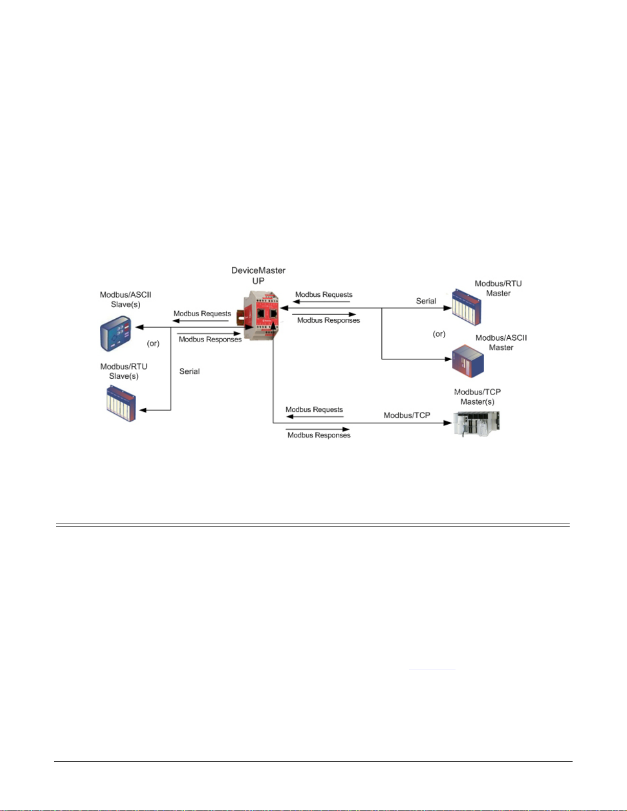
Configuring Modbus/RTU and Modbus/ASCII Slaves
Modbus Master(s) to Modbus Slave(s)
and Masters
For pure Modbus devices, the DeviceMaster UP supports:
• Modbus/RTU serial slaves
• Modbus ASCII serial slaves
• Modbus/RTU serial masters
• Modbus/ASCII serial masters
• Modbus/TCP masters
Note: All masters can communicate to all slaves.
Prerequisites
Before you can configure the serial ports for this mode, make sure that you have done the following:
• Installed the hardware
• Installed PortVision DX
• Configured the DeviceMaster UP IP address using PortVision DX
• If necessary, uploaded the latest Modbus/TCP firmware using PortVision DX
Note: The DeviceMaster UP provides an Modbus/TCP interface, which may or may not have the Modbus/
TCP firmware loaded (depending on the model you purchased). Models that have Modbus/TCP loaded
on the DeviceMaster UP are identified in PortVision DX and the DeviceMaster UP is labeled
accordingly.
If you need to perform any of these procedures or locate the latest files, see Overview
on Page 5.
Modbus/TCP Quick Start: 2000477 Rev. G Configuring Modbus/RTU and Modbus/ASCII Slaves and Masters - 9
Page 10

Configuring Modbus/RTU and Modbus/ASCII Slaves and Masters
Configuring Modbus/RTU Slaves
Use the following procedure to configure a serial interface to Modbus/RTU slave(s).
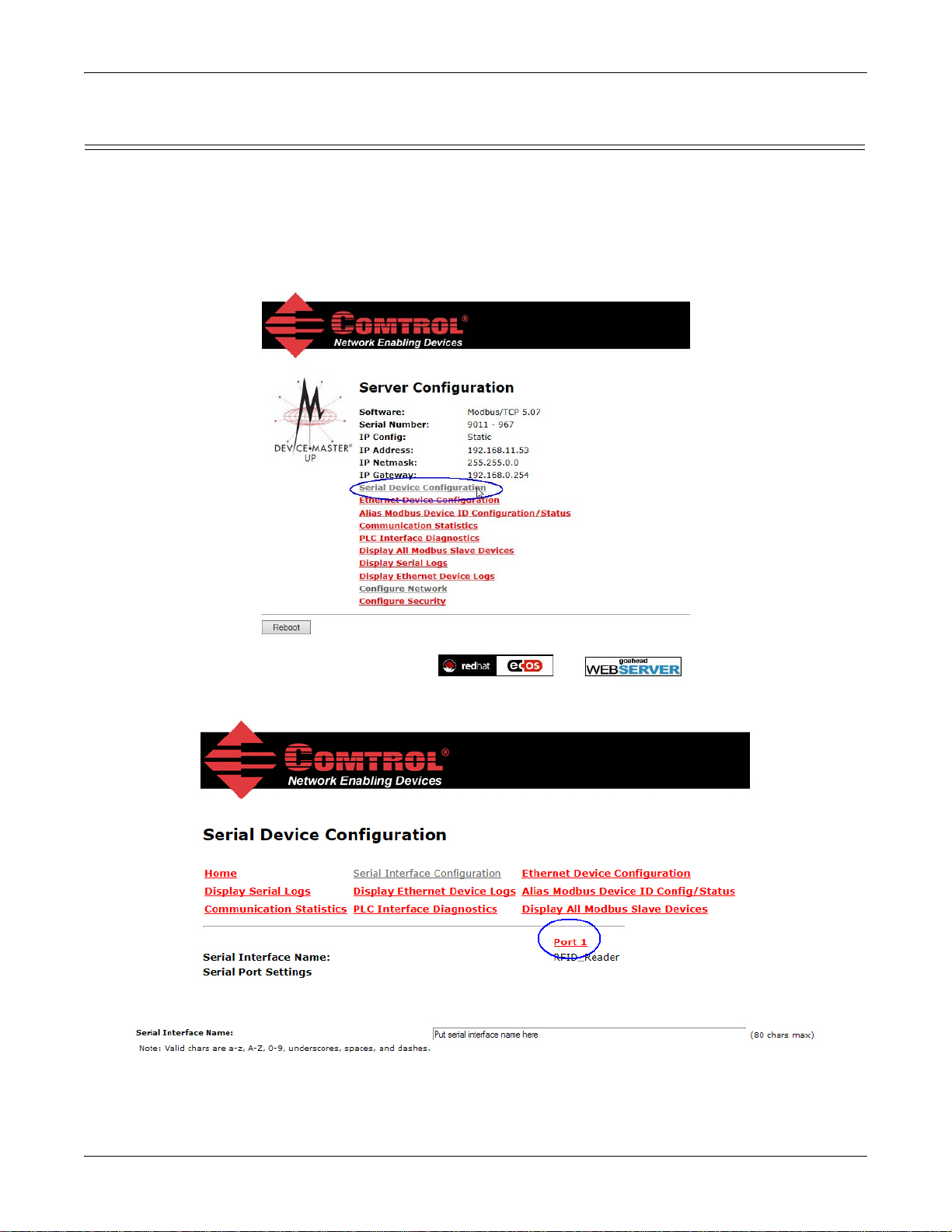
1. Access the Server Configuration web page by entering the DeviceMaster UP IP address in your web
browser or by highlighting the DeviceMaster UP in PortVision DX and clicking Webpage.
Note: If the browser does not display the web page correctly, clear the browser history and refresh the
DeviceMaster UP web page.
2. Click the Serial Device Configuration link to open the Serial Device Configuration page.
3. Click Port N for the port you want to configure, where N is the port number.
4. If desired, provide a Serial Interface Name.
10 - Configuring Modbus/RTU and Modbus/ASCII Slaves and Masters Modbus/TCP Quick Start: 2000477 Rev. G
Page 11

Configuring Modbus/RTU and Modbus/ASCII Slaves and Masters
5. Set up the Serial Configuration for your device.
6. Configure the serial port for Modbus/RTU-to-Slaves operation. Under General Protocol Settings:
a. Set Serial Port Protocol to Modbus/RTU-to-Slaves.
b. Enable Discard Rx Packets With Errors.
c. Under Modbus Slave and Raw-Data Device Settings, set the Device Response Timeout value or leave at
the default.
d. 2/4-port models only
: Under Modbus Slaves Only, enable Lost Device Search Enable if you want the
DeviceMaster UP to search for a lost Modbus slave device on other Modbus/RTU and/or Modbus/
ASCII slave ports that also have this option enabled.
7. Scroll to the bottom of the page, verify that Reset Port and Save in Flash are selected, and click Submit.
Note: If necessary, see Filtering/Data Extraction Configuration
on Page 61 or Application Socket
Configuration on Page 67 for additional configuration procedures.
Modbus/TCP Quick Start: 2000477 Rev. G Configuring Modbus/RTU and Modbus/ASCII Slaves and Masters - 11
Page 12
Configuring Modbus/RTU and Modbus/ASCII Slaves and Masters
Configuring Modbus/ASCII Slaves
Use the following procedure to configure a serial interface to Modbus/ASCII slave(s).
1. Access the Server Configuration web page by entering the DeviceMaster UP IP address in your web
browser or by highlighting the DeviceMaster UP in PortVision DX and clicking Webpage.
Note: If the browser does not display the web page correctly, clear the browser history and refresh the
DeviceMaster UP web page.
2. Click the Serial Device Configuration option to open the Serial Device Configuration page.
3. Click Port N for the port you want to configure, where N is the port number.
4. If desired, provide a Serial Interface Name.
12 - Configuring Modbus/RTU and Modbus/ASCII Slaves and Masters Modbus/TCP Quick Start: 2000477 Rev. G
Page 13

Configuring Modbus/RTU and Modbus/ASCII Slaves and Masters
5. Set up the Serial Configuration for your device.
6. Configure the serial port for Modbus/ASCII-to-Slaves operation. Under General Protocol Settings:
a. Set Serial Port Protocol to Modbus/ASCII-to-Slaves.
b. Enable Discard Rx Packets With Errors.
c. Under Modbus Slave and Raw-Data Device Settings, set the Device Response Timeout value or leave at
the default.
d. 2/4-port models only: Under Modbus Slaves Only, enable Lost Device Search Enable if you want the
DeviceMaster UP to search for a lost Modbus slave device on other Modbus/RTU and/or Modbus/
ASCII slave ports that also have this option enabled.
7. Scroll to the bottom of the page, verify that Reset Port and Save in Flash are selected, and click Submit.
Note: If necessary, see Filtering/Data Extraction Configuration
on Page 61 or Application Socket
Configuration on Page 67 for additional configuration procedures.
Modbus/TCP Quick Start: 2000477 Rev. G Configuring Modbus/RTU and Modbus/ASCII Slaves and Masters - 13
Page 14

Configuring Modbus/RTU and Modbus/ASCII Slaves and Masters
Configuring Modbus/RTU Master
Use the following procedure to configure a serial interface to Modbus/RTU master.
1. Access the Server Configuration web page by entering the DeviceMaster UP IP address in your web
browser or by highlighting the DeviceMaster UP in PortVision DX and clicking Webpage.
Note: If the browser does not display the web page correctly, clear the browser history and refresh the
DeviceMaster UP web page.
2. Click the Serial Device Configuration option to open the Serial Device Configuration page.
3. Click Port N for the port you want to configure, where N is the port number.
4. If desired, provide a Serial Interface Name.
14 - Configuring Modbus/RTU and Modbus/ASCII Slaves and Masters Modbus/TCP Quick Start: 2000477 Rev. G
Page 15

Configuring Modbus/RTU and Modbus/ASCII Slaves and Masters
5. Set up the Serial Configuration for your device.
6. Configure the serial port for Modbus/RTU-to-Master operation. Under General Protocol Settings:
a. Set Serial Port Protocol to Modbus/RTU-to-Master.
b. Enable Discard Rx Packets With Errors.
7. Scroll to the bottom of the page, verify that Reset Port and Save in Flash are selected, and click Submit.
Note: If necessary, see Filtering/Data Extraction Configuration
on Page 61 or Application Socket
Configuration on Page 67 for additional configuration procedures.
Modbus/TCP Quick Start: 2000477 Rev. G Configuring Modbus/RTU and Modbus/ASCII Slaves and Masters - 15
Page 16

Configuring Modbus/RTU and Modbus/ASCII Slaves and Masters
Configuring Modbus/ASCII Master
Use the following procedure to configure a serial interface to Modbus/ASCII master.
1. Access the Server Configuration web page by entering the DeviceMaster UP IP address in your web
browser or by highlighting the DeviceMaster UP in PortVision DX and clicking Webpage.
Note: If the browser does not display the web page correctly, clear the browser history and refresh the
DeviceMaster UP web page.
2. Click the Serial Device Configuration option to open the Serial Device Configuration page.
3. Click Port N for the port you want to configure, where N is the port number.
4. If desired, provide a Serial Interface Name.
16 - Configuring Modbus/RTU and Modbus/ASCII Slaves and Masters Modbus/TCP Quick Start: 2000477 Rev. G
Page 17

Configuring Modbus/RTU and Modbus/ASCII Slaves and Masters
5. Set up the Serial Configuration for your device.
6. Configure the serial port for Modbus/ASCII-to-Master operation. Under General Protocol Settings:
a. Set Serial Port Protocol to Modbus/ASCII-to-Master.
b. Enable Discard Rx Packets With Errors.
7. Scroll to the bottom of the page, verify that Reset Port and Save in Flash are selected, and click Submit.
Note: If necessary, see Filtering/Data Extraction Configuration
on Page 61 or Application Socket
Configuration on Page 67 for additional configuration procedures.
Modbus/TCP Quick Start: 2000477 Rev. G Configuring Modbus/RTU and Modbus/ASCII Slaves and Masters - 17
Page 18

Configuring Modbus/RTU and Modbus/ASCII Slaves and Masters
18 - Configuring Modbus/RTU and Modbus/ASCII Slaves and Masters Modbus/TCP Quick Start: 2000477 Rev. G
Page 19
Configuring Read-Only Raw/ASCII Devices
Serial Read-Only Device Communications
This chapter contains these subsections:
• Prerequisites (below)
• Read-Only Raw/ASCII Serial Devices (below)
•
Read-Only Raw/ASCII Ethernet Devices on Page 26
Prerequisites
Before you can configure the ports, make sure that you have done the following:
• Installed the hardware
• Installed PortVision DX
• Configured the DeviceMaster UP IP address using PortVision DX
• If necessary, uploaded the latest Modbus/TCP firmware using PortVision DX
Note: The DeviceMaster UP provides a Modbus/TCP interface, which may or may not have the Modbus/TCP
If you need to perform any of these procedures or locate the latest files, see
firmware loaded (depending on the model you purchased). Models that have Modbus/TCP loaded on
the DeviceMaster UP are identified in PortVision DX and the DeviceMaster UP is labeled accordingly.
Overview on Page 5.
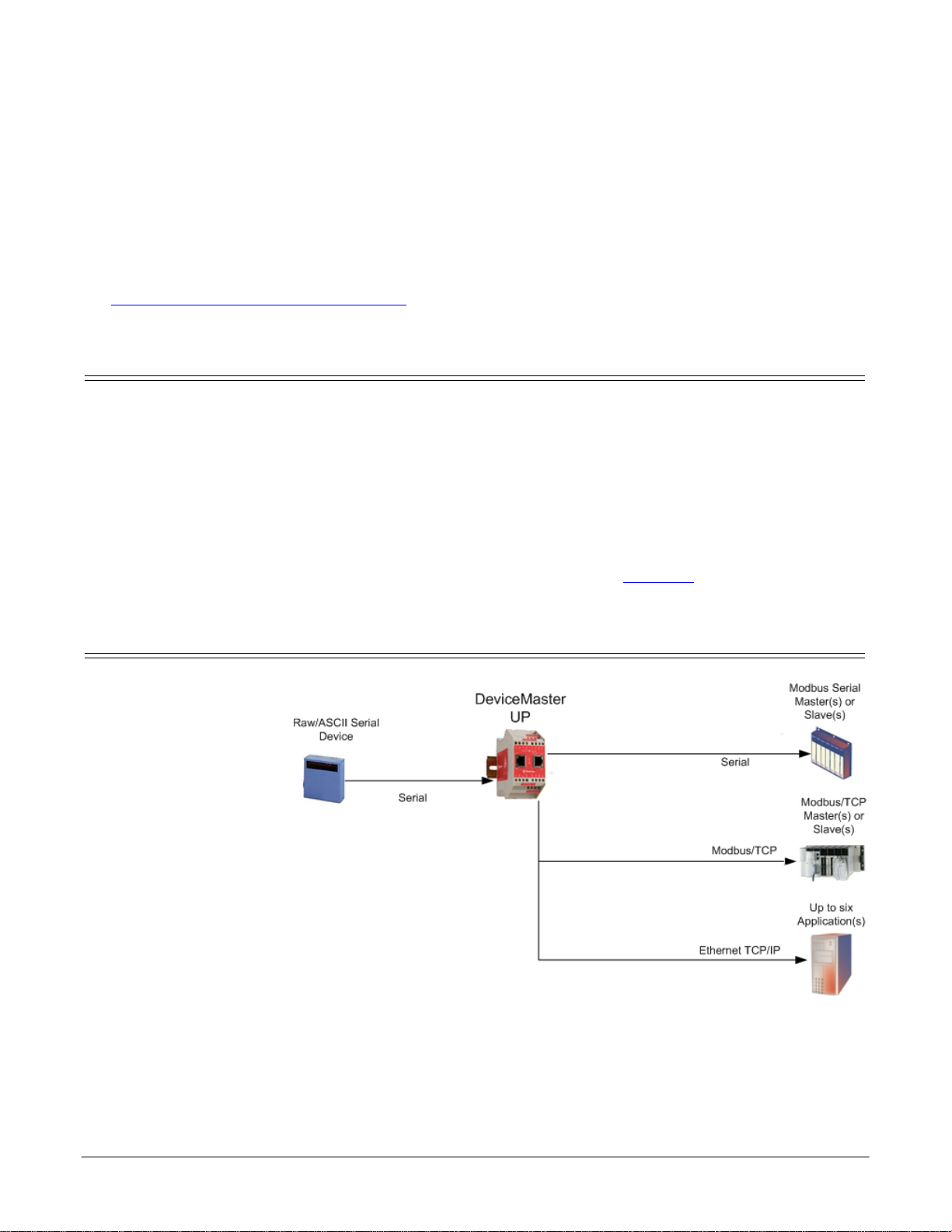
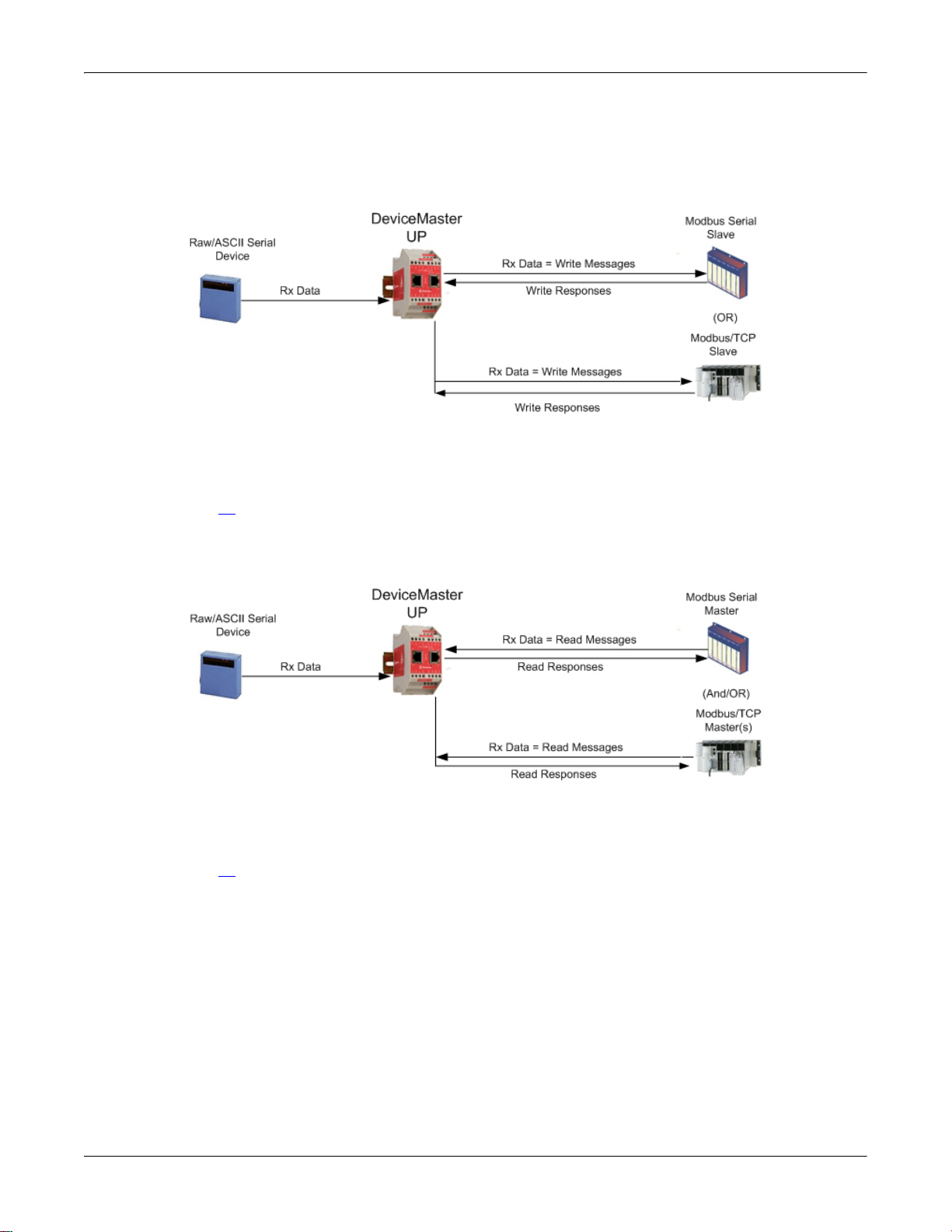
Read-Only Raw/ASCII Serial Devices
Read-only raw/ASCII serial
devices use the Serial
Device Configuration page
to:
• Allow connections
between a serial device,
such as a barcode
scanner or RFID
reader, to PLC(s) and/
or application(s).
• Provide an optional
filtering mechanism for
string, RFID, and
barcode data.
The PLC and application
can both communicate to
the serial device, but they
cannot communicate
directly to each other.
DeviceMaster UP Modbus/TCP Quick Start: 2000477 Rev. G Configuring Read-Only Raw/ASCII Devices - 19
Page 20
Configuring Read-Only Raw/ASCII Devices
Embedded Web Page Configuration
Use the following procedure to configure read-only raw/ASCII serial devices.
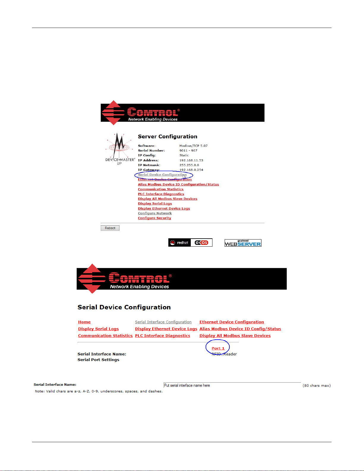
1. Access the Server Configuration web page by entering the DeviceMaster UP IP address in your web
browser or by highlighting the DeviceMaster UP in PortVision DX and clicking Webpage.
Note: If the browser does not display the web page correctly, clear the browser history and refresh the
DeviceMaster UP web page.
2. Click the Serial Device Configuration option to open the Serial Device Configuration page.
3. Click Port N for the port you want to configure, where N is the port number.
4. If desired, provide a Serial Interface Name.
20 - Configuring Read-Only Raw/ASCII Devices DeviceMaster UP Modbus/TCP Quick Start: 2000477 Rev. G
Page 21

Configuring Read-Only Raw/ASCII Devices
5. Set the Serial Configuration for your device.
6. Set the General Protocol Settings:
a. Set Serial Port Protocol to Raw-Data.
b. Enable Discard Rx Packets With Errors.
7. Set the Message Transfer mode, by setting the Raw-Data Message Transfer Mode to Data-Stream.
8. Set up the serial packet
identification (Serial Packet ID
Settings (Raw Data Only).
• Set the STX (Start of
transmission) Rx Detect in
decimal format.
• Set the ETX (End of
transmission) Rx Detect in
decimal format.
• Enable the S trip Rx STX/ETX
option if you do not want the
STX and ETX bytes returned
to the PLC or application(s).
Note: Refer to your device's User Manual for the Start and End of Transmission byte(s) settings. You may
also be able to use the Serial Interface Logs page to determine these settings.
DeviceMaster UP Modbus/TCP Quick Start: 2000477 Rev. G Configuring Read-Only Raw/ASCII Devices - 21
Page 22
Configuring Read-Only Raw/ASCII Devices
You can use the Master Receive Transfer method only if your PLC can
operate as a Modbus/TCP slave, Modbus/RTU serial slave, or Modbus/
ASCII serial slave.
You can use the Slave Receive
Transfer method only if your PLC can operate as a Modbus/TCP master,
Modbus/RTU serial master, or Modbus/ASCII serial master.
9. Configure the Modbus/TCP and/or Serial Modbus Master Settings for your environment using one of the
following settings:
• Master Receive Transfer mode (recommended) writes data directly into the memory of a Modbus/
TCP slave or serial Modbus slave attached to this gateway. This requires the least amount of PLC
programming, requires the least amount of PLC overhead, and provides minimal latency.
Go to Step 10
on Page 23 to configure Master Receive Transfer mode.
• Slave Receive Transfer mode requires the PLC to poll for received data. This method is provided for
PLC programmers who prefer polling for data or those who have PLCs that can only operate in master
mode.
Go to Step 11
on Page 24 to configure Slave Receive Transfer mode.
22 - Configuring Read-Only Raw/ASCII Devices DeviceMaster UP Modbus/TCP Quick Start: 2000477 Rev. G
Page 23
Configuring Read-Only Raw/ASCII Devices
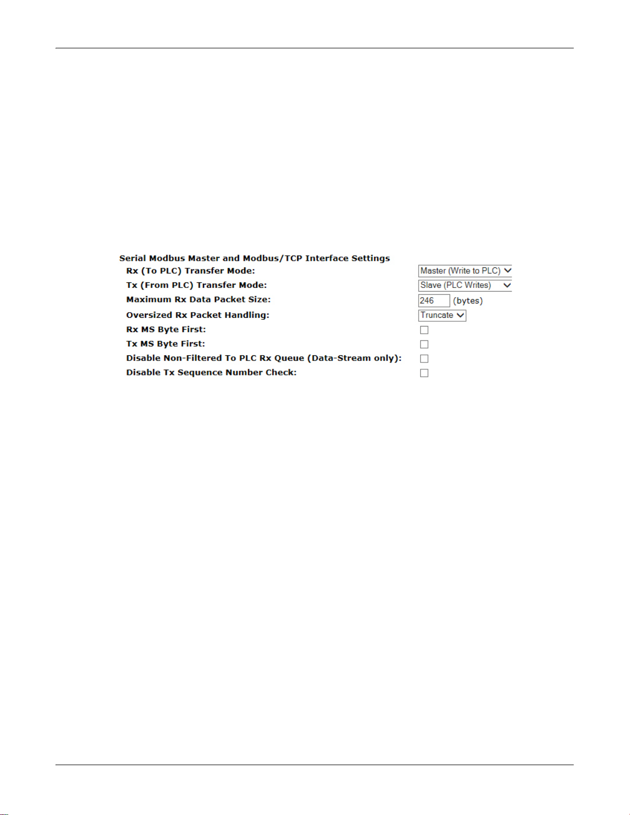
10. Master Receive Transfer Mode Only
Use the following procedure to configure Master Receive Transfer mode.
Under Serial Modbus Master and Modbus/TCP Settings (Raw-Data Only):
a. Set Rx (To PLC) Transfer Mode to Master (Write to PLC).
b. Set Tx (From PLC) Transfer Mode to either Slave (PLC Writes) or Off.
c. Set the Maximum Rx Data Packet Size to that of the largest expected receive data packet. For writing to
a Modbus/TCP slave or Modbus serial slave, this can be a maximum of 1,518 bytes.
d. Set the Oversized Rx Packet Handling to either Truncate or Drop, depending how you want to handle
oversized received packets.
e. Set Rx MS Byte First if you want to receive data most significant byte first.
f. Set the Disable Non-Filtered To PLC Rx Queue option if you only want to receive the last received data
packet. (If two or more packets are received during the Maximum PLC Update Rate time period, only
the last received data packet will be sent to the PLC.)
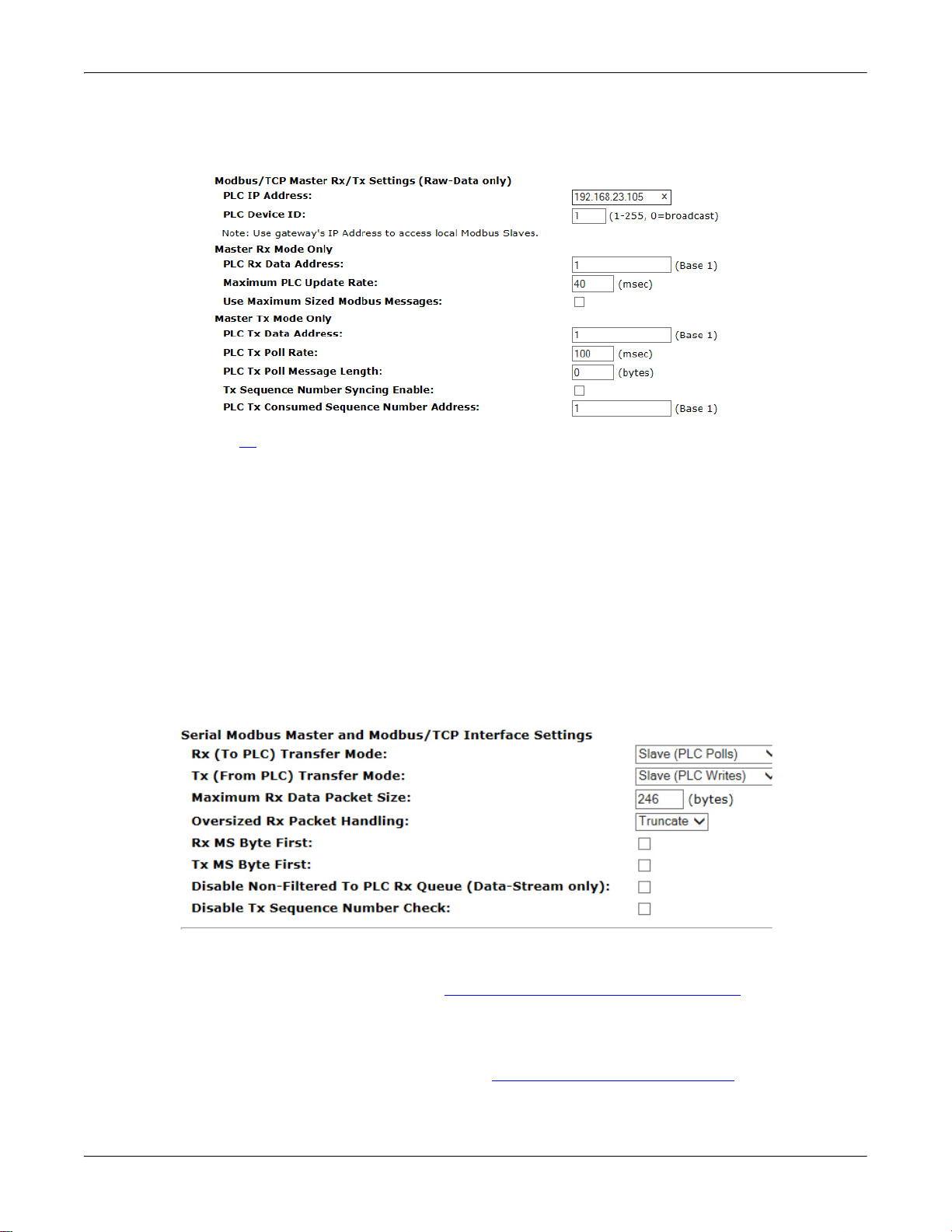
Under Modbus/TCP Master Rx/Tx Settings (Raw-Data Only):
g. Enter the PLC IP Address:
• For Modbus/TCP slaves, set the PLC IP Address to that of your PLC in xxx.xxx.xxx.xxx format.
• For Modbus/RTU or Modbus/ASCII serial slaves, set the PLC IP Address to that of this
DeviceMaster UP in xxx.xxx.xxx.xxx format.
Note: The Modbus serial slave must be attached to one of the serial ports on this DeviceMaster UP
chassis.
h. Enter the PLC Device ID:
• For Modbus/TCP slaves, set the PLC Device ID to that of your PLC. This is typically 1.
• For Modbus/RTU or Modbus/ASCII serial slaves, set the PLC Device ID to that of the serial slave
device.
Note: This must be a unique device id attached to this DeviceMaster UP chassis.
i. Set the PLC Rx Data Address to the PLC memory address where you want to place the received data
message. This address is Base 1, which means the address starts at 1 (or 400001 for some PLCs). If
your address range is Base 0, or starts at zero, you will need to add one to your address.
j. Set the Maximum PLC Update Rate to the fastest rate your PLC can reliably receive and process data.
This is typically longer than the scan rate. The default of 40 milliseconds is usually sufficient, but
your system may require a longer time period.
DeviceMaster UP Modbus/TCP Quick Start: 2000477 Rev. G Configuring Read-Only Raw/ASCII Devices - 23
Page 24
Configuring Read-Only Raw/ASCII Devices
k. Set the Use Maximum Sized Modbus Messages option if you are receiving messages over 196 bytes, your
PLC can receive messages larger than 200 bytes, and you want to decrease latency and network
usage.
Note: Go to Step 12
on Page 24 to complete configuration.
11. Slave Receive Transfer Mode Only:
Use the following procedure to configure Slave Receive Transfer mode.
Under Serial Modbus Master and Modbus/TCP Settings (Raw-Data Only):
a. Set Rx (To PLC) Transfer Mode to Slave (PLC Polls).
b. Set Tx (From PLC) Transfer Mode to either Slave (PLC Writes) or Off.
c. Set the Maximum Rx Data Packet Size to that of the largest expected receive data packet. This can be a
maximum of 246 bytes in Slave Rx mode.
d. Set the Oversized Rx Packet Handling to either Truncate or Drop, depending how you want to handle
oversized received packets.
e. Set Rx MS Byte First if you want to receive data most significant byte first.
f. Set the Disable Non-Filtered To PLC Rx Queue option if you only want to receive the last received data
packet. (If two or more packets are received between received data requests, only the last received
data packet will be returned.)
12. Set up the filtering/data extraction settings:
• If no filtering/data extraction is required, leave all filtering/data extraction settings to defaults (off).
• If filtering/data extraction is required, see
Filtering/Data Extraction Configuration on Page 61.
13. Set up the application socket interface settings:
• If no application socket interface is required, leave all application socket interface settings at defaults
and the application Enable option in not selected.
• If an application socket interface is required, see
Application Socket Configuration on Page 67.
14. Scroll to the bottom of the page, verify that Reset Port and Save in Flash are selected, and click Submit.
24 - Configuring Read-Only Raw/ASCII Devices DeviceMaster UP Modbus/TCP Quick Start: 2000477 Rev. G
Page 25

Configuring Read-Only Raw/ASCII Devices
Modbus Raw Data Addressing
The serial port receive data addresses used for polling:
Serial Port
Raw/ASCII
Serial Port 1 Serial Port 2 Serial Port 3 Serial Port 4 Access Rule
Addressing
Unit ID 255 (FF Hex) 255 (FF Hex) 255 (FF Hex) 255 (FF Hex) N/A
Receive Data
Address
1000 (Base 0)
1001 (Base 1)
2000 (Base 0)
2001 (Base 1)
3000 (Base 0)
3001 (Base 1)
4000 (Base 0)
4001 (Base 1)
Read Only
Received Message Format
If all is set up correctly, the data packets will be written into the PLC memory space starting at the specified
memory location. The first word received is the sequence number. This is incremented with each new data
packet. The next word is the length, which indicates the number of data bytes received. The rest is data.
The format of received serial data sent to or returned to the PLC:
Name Data Type Data Value(s)
Receive (DeviceMaster UP to PLC)
message data.
Structure of:
Produced data sequence
Data length (in bytes)
Data array
WORD
WORD
Array of
WORD
0-65535 (
FFFF Hex)
1-1024 (Master Rx Mode)
0-246 (Slave Rx Mode)
0-65535
Access
Rule
Get
General requirements:
• The memory area must be defined in 16 bit words and large enough to handle the largest serial packet
plus two words for the produced sequence number and data length parameters.
•The Maximum Rx Data Packet Size must be set large enough to accept the largest possible packet.
• For large received data packets over 246 bytes (This may be less for your PLC):
The Rx (To PLC) Transfer Mode must be set to Master (Write to PLC).
- The data will automatically be placed in continuous memory.
- All data will have been transferred to the PLC when the sequence number is updated.
DeviceMaster UP Modbus/TCP Quick Start: 2000477 Rev. G Configuring Read-Only Raw/ASCII Devices - 25
Page 26

Configuring Read-Only Raw/ASCII Devices
Ethernet TCP/IP Read-Only device Communications
Caution
Read-Only Raw/ASCII Ethernet Devices
Read-only raw/ASCII Ethernet devices use the Ethernet Device Configuration page to:
• Allow connections between devices that communicate over Ethernet TCP/IP, such as a barcode scanner,
RFID reader, or weigh scale, and a PLC and/or application.
• Provide an optional filtering mechanism for string, RFID, and barcode data.
• Provide support for only Raw/ASCII type data.
Verify that you have an actual Ethernet device in which to connect to and that the Ethernet device supports
Ethernet TCP socket connections.
Do not use this configuration page for serial devices.
26 - Configuring Read-Only Raw/ASCII Devices DeviceMaster UP Modbus/TCP Quick Start: 2000477 Rev. G
Page 27

Configuring Read-Only Raw/ASCII Devices
Embedded Web Page Configuration
Use the following procedure to configure read-only Ethernet devices.
1. Access the Server Configuration web page by entering the DeviceMaster UP IP address in your web
browser or by highlighting the DeviceMaster UP in PortVision DX and clicking Webpage.
Note: If the browser does not display the web page correctly, clear the browser history and refresh the
DeviceMaster UP web page.
2. Click the Ethernet Device Configuration option to open the Ethernet Device Configuration page.
Note: The Ethernet device must be a target Ethernet device such as a barcode scanner, RFID reader,
weigh scale, or some other device that is to be connected to a PLC and/or application.
3. Click Socket N for the port that you want to configure, where N is the Socket number.
4. If desired, enter an Ethernet Interface Name.
5. Click Enable under Device TCP Connection Configuration and configure the settings for your environment
using one of the following procedures.
DeviceMaster UP Modbus/TCP Quick Start: 2000477 Rev. G Configuring Read-Only Raw/ASCII Devices - 27
Page 28

Configuring Read-Only Raw/ASCII Devices
Connect Mode Set Up
Listen Mode Set Up
Listen and Connect Modes Set Up
• If your Ethernet TCP/IP device requires
another device to connect to it, configure
the socket port on the DeviceMaster UP to
Connect mode:
- Leave Listen unselected.
-Set Connect To Mode to Connect-Always.
- Set the Connect Port to the socket port
number of your Ethernet device.
- Set the Connect IP Address to the IP
address of your Ethernet device.
Do not enter the IP address of the
DeviceMaster UP or PLC here.
-Set Disconnect Mode to Never.
• If your Ethernet TCP/IP device is
configured to connect to another device,
configure the socket port on the
DeviceMaster UP to Listen mode:
-Select Listen.
- Use the default Listen Port on the
DeviceMaster UP of 8xxx or designate
your own.
-Set Connect To Mode to Never.
-Set Disconnect Mode to Never.
- Configure your Ethernet device to
connect to the DeviceMaster UP at the DeviceMaster UP IP address and Listen Port.
• If you do not know if your device will connect
to another Ethernet device, but do know
your device’s socket port and IP address, you
can do the following to enable both the Listen
and Connect modes:
-Select Listen.
- Use the default Listen Port on the
DeviceMaster UP of 8xxx or designate
your own.
-Set Connect To Mode to Connect-Always.
-Set the Connect Port to the port number
of your Ethernet device.
- Set the Connect IP Address to the IP address of your Ethernet device.
Do not enter the IP address of the DeviceMaster UP or PLC here.
-Set Disconnect Mode to Never.
- Optionally configure your Ethernet device to connect to the DeviceMaster UP at the DeviceMaster
UP IP address and Listen Port.
6. Set up the Message Transfer Settings, by setting the Message Transfer Mode to Data-Stream.
28 - Configuring Read-Only Raw/ASCII Devices DeviceMaster UP Modbus/TCP Quick Start: 2000477 Rev. G
Page 29

Configuring Read-Only Raw/ASCII Devices
7. Set up the Socket Packet Identification.
a. Set the Rx Timeout Between Packets. Set to zero to stream data with the Rx STX/ETX Detect settings set
to none. For normal settings, typical values are 10 to 50 ms.
b. Set the STX (Start of transmission) Rx Detect in decimal format.
c. Set the ETX (End of transmission) Rx Detect in decimal format.
d. Enable the Strip Rx STX/ETX option if you do not want the STX and ETX bytes returned to the PLC or
application.
Note: Refer to your device's User Manual for the Start and End of Transmission byte(s) settings. You may
also be able to use the Ethernet Device Interface Logs page to determine these settings.
DeviceMaster UP Modbus/TCP Quick Start: 2000477 Rev. G Configuring Read-Only Raw/ASCII Devices - 29
Page 30

Configuring Read-Only Raw/ASCII Devices
You can use the Master Receive Transfer method only if your PLC can operate as a
Modbus/TCP slave, Modbus/RTU serial slave, or Modbus/ASCII serial slave.
You can use the Slave Receive Transfer method only if your PLC can operate as a
Modbus/TCP master, Modbus/RTU serial master, or Modbus/ASCII serial master.
8. Configure the Modbus/TCP and/or Serial Modbus Master Settings for your environment using one of the
following methods.
• Master Receive Transfer mode (recommended) writes data directly into the memory of a Modbus/
TCP slave or serial Modbus slave attached to this gateway. This requires the least amount of PLC
programming, requires the least amount of PLC overhead, and provides minimal latency.
Go to Step 9
on Page 31 to configure Master Receive Transfer mode.
• Slave Receive Transfer mode requires the PLC to poll for received data. This method is provided for
PLC programmers who prefer polling for data or those who have PLCs that can only operate in master
mode.
Go to Step 10
on Page 32 to configure Slave Receive Transfer mode.
30 - Configuring Read-Only Raw/ASCII Devices DeviceMaster UP Modbus/TCP Quick Start: 2000477 Rev. G
Page 31

Configuring Read-Only Raw/ASCII Devices
9. Master Receive Transfer Mode Only:
Use the following procedure to configure Master Receive Transfer mode.
Under Serial Modbus Master and Modbus/TCP Settings (Raw-Data Only):
a. Set Rx (To PLC) Transfer Mode to Master (Write to PLC).
b. Set Tx (From PLC) Transfer Mode to either Slave (PLC Writes) or Off.
c. Set the Maximum Rx Data Packet Size to that of the largest expected receive data packet. For writing to
a Modbus/TCP slave or Modbus serial slave, this can be a maximum of 1,518 bytes.
d. Set the Oversized Rx Packet Handling to either Truncate or Drop, depending how you want to handle
oversized received packets.
e. Set Rx MS Byte First if you want to receive data most significant byte first.
f. Set the Disable Non-Filtered To PLC Rx Queue option if you only want to receive the last received data
packet. (If two or more packets are received during the Maximum PLC Update Rate time period, only
the last received data packet will be sent to the PLC.)
Under Modbus/TCP Master Rx/Tx Settings (Raw-Data Only):
g. Enter the PLC IP Address:
• For Modbus/TCP slaves, set the PLC IP Address to that of your PLC in xxx.xxx.xxx.xxx format.
• For Modbus/RTU or Modbus/ASCII serial slaves, set the PLC IP Address to that of this
DeviceMaster UP in xxx.xxx.xxx.xxx format.
Note: The Modbus serial slave must be attached to one of the serial ports on this DeviceMaster UP
chassis.
h. Enter the PLC Device ID:
• For Modbus/TCP slaves, set the PLC Device ID to that of your PLC. This is typically 1.
• For Modbus/RTU or Modbus/ASCII serial slaves, set the PLC Device ID to that of the serial slave
device.
Note: This must be a unique device id attached to this DeviceMaster UP chassis.
i. Set the PLC Rx Data Address to the PLC memory address where you want to place the received data
message. This address is Base 1, which means the address starts at 1 (or 400001 for some PLCs). If
your address range is Base 0, or starts at zero, you will need to add one to your address.
j. Set the Maximum PLC Update Rate to the fastest rate your PLC can reliably receive and process data.
This is typically longer than the scan rate. The default of 40 milliseconds is usually sufficient, but
your system may require a longer time period.
DeviceMaster UP Modbus/TCP Quick Start: 2000477 Rev. G Configuring Read-Only Raw/ASCII Devices - 31
Page 32

Configuring Read-Only Raw/ASCII Devices
k. Set the Use Maximum Sized Modbus Messages option if you are receiving messages over 196 bytes, your
PLC can receive messages larger than 200 bytes, and you want to decrease latency and network usage
l. Go to Step 11
on Page 32 to complete configuration.
10. Slave Receive Transfer Mode Only:
Use the following procedure to configure the Slave Receive Transfer mode.
Under Serial Modbus Master and Modbus/TCP Settings (Raw-Data Only):
a. Set Rx (To PLC) Transfer Mode to Slave (PLC Polls).
b. Set Tx (From PLC) Transfer Mode to either Slave (PLC Writes) or Off.
c. Set the Maximum Rx Data Packet Size to that of the largest expected receive data packet. This can be a
maximum of 246 bytes in Slave Rx Mode.
d. Set the Oversized Rx Packet Handling to either Truncate or Drop, depending how you want to handle
oversized received packets.
e. Set Rx MS Byte First if you want to receive data most significant byte first.
f. Set the Disable Non-Filtered To PLC Rx Queue option if you only want to receive the last received data
packet. (If two or more packets are received between received data requests, only the last received
data packet will be returned.)
11. Set up the Filtering/Data Extraction Configuration settings:
• If no filtering/data extraction is required, leave all filtering/data extraction settings to defaults (off).
• If filtering/data extraction is required, see
32 - Configuring Read-Only Raw/ASCII Devices DeviceMaster UP Modbus/TCP Quick Start: 2000477 Rev. G
Filtering/Data Extraction Configuration on Page 61.
Page 33

Configuring Read-Only Raw/ASCII Devices
12. Set up the Application TCP Connection Configuration settings:
• If no application socket interface is required, leave all application socket interface settings at defaults
and the application Enable option is not selected.
• If an application socket interface is required, see
Application Socket Configuration on Page 67.
13. Scroll to the bottom of the page, verify that Reset Port and Save in Flash are selected, and click Submit.
Modbus Addressing
The receive data addresses used for polling are as follows:
Socket Port Raw/
ASCII Addressing
Socket Port 1Socket Port 2Socket Port 3Socket Port
4
Access Rule
Unit ID 254 (FF Hex) 254 (FF Hex) 254 (FF Hex) 254 (FF Hex) N/A
Receive Data Address
1000 (Base 0)
1001 (Base 1)
2000 (Base 0)
2001 (Base 1)
3000 (Base 0)
3001 (Base 1)
4000 (Base 0)
4001 (Base 1)
Read Only
Received Message Format
If all is set up correctly, the data packets will be written into the PLC memory space starting at the specified
memory location. The first word received is the sequence number. This is incremented with each new data
packet. The next word is the length, which indicates the number of data bytes received. The rest is data.
The format of received socket data sent to the PLC:
Name Data Type Data Value(s)
Receive (DeviceMaster UP to PLC)
message data.
Structure of:
Produced data sequence
Data length (in bytes)
Data array
WORD
WORD
Array of
WORD
0-65535 (FFFF Hex)
1-2048 (Master Rx Mode)
0-246 (Slave Rx Mode)
0-65535
Access
Rule
Get
General requirements:
• The memory area must be defined in 16 bit words and large enough to handle the largest serial packet
plus two words for the produced sequence number and data length parameters.
•The Maximum Rx Data Packet Size must be set large enough to accept the largest possible packet.
For large received data packets over 246 bytes (This may be less for your PLC):
-The Rx (To PLC) Transfer Mode must be set to Master (Write to PLC).
- The data will automatically be placed in continuous memory.
- All data will have been transferred to the PLC when the sequence number is updated.
DeviceMaster UP Modbus/TCP Quick Start: 2000477 Rev. G Configuring Read-Only Raw/ASCII Devices - 33
Page 34

Configuring Read-Only Raw/ASCII Devices
34 - Configuring Read-Only Raw/ASCII Devices DeviceMaster UP Modbus/TCP Quick Start: 2000477 Rev. G
Page 35

Configuring Read/Write Raw/ASCII Devices
This section discusses the following:
• Prerequisites
•
Read/Write Raw/ASCII Serial Devices on Page 36
•
Read/Write Raw/ASCII Ethernet Devices on Page 47
Prerequisites
Before you can configure the ports, make sure that you have done the following:
• Installed the hardware
• Installed PortVision DX
• Configured the DeviceMaster UP IP address using PortVision DX
• If necessary, uploaded the latest Modbus/TCP firmware using PortVision DX
Note: The DeviceMaster UP provides a Modbus/TCP interface, which may or may not have the Modbus/TCP
If you need to perform any of these procedures or locate the latest files, see
firmware loaded (depending on the model you purchased). Models that have Modbus/TCP loaded on
the DeviceMaster UP are identified in PortVision DX and the DeviceMaster UP is labeled accordingly.
Overview on Page 5.
DeviceMaster UP Modbus/TCP Quick Start: 2000477 Rev. G Configuring Read/Write Raw/ASCII Devices - 35
Page 36

Configuring Read/Write Raw/ASCII Devices
Serial Read/Write Device Communications
Read/Write Raw/ASCII Serial Devices
Read/write raw/ASCII serial devices use the Serial Device Configuration page to:
• Allow connections between a serial device, such as a barcode scanner or RFID reader, and a PLC and/or
application(s).
• Provide an optional filtering mechanism for string, RFID, and barcode data.
Note: The PLC and application(s) can both communicate to the serial device, but they cannot communicate
directly to each other.
36 - Configuring Read/Write Raw/ASCII Devices DeviceMaster UP Modbus/TCP Quick Start: 2000477 Rev. G
Page 37

Configuring Read/Write Raw/ASCII Devices
Embedded Web Page Configuration
Use the following procedure to configure read/write raw/ASCII serial devices.
1. Access the Server Configuration web page by entering the DeviceMaster UP IP address in your web
browser or by highlighting the DeviceMaster UP in PortVision DX and clicking Webpage.
Note: If the browser does not display the web page correctly, clear the browser history and refresh the
DeviceMaster UP web page.
2. Click the Serial Device Configuration option to open the Serial Device Configuration page.
3. Click Port N for the port that you want to configure, where N is the port number.
4. If desired, provide a Serial Interface Name.
DeviceMaster UP Modbus/TCP Quick Start: 2000477 Rev. G Configuring Read/Write Raw/ASCII Devices - 37
Page 38

Configuring Read/Write Raw/ASCII Devices
5. Set up the Serial Configuration for your device.
6. Select the Modbus/TCP communication method and set up the Modbus/TCP Interface settings under
General Protocol Settings:
a. Set Serial Port Protocol to Raw-Data.
b. Enable Discard Rx Packets With Errors.
7. Set the Raw-Data Message Transfer mode:
• Selecting Data-Stream enables asynchronous communication to the device.
- Transmit data is sent immediately from all Modbus and active Application interfaces.
- Received data will be returned to the Modbus interface and all active Application interfaces.
-If Data-Stream is selected, the rest of the options in this section are not applicable.
• Selecting Command/Response enables synchronous communications with the device.
- Transmit data will expect one or more responses.
- Responses will only be returned to the transmit message originator.
If Command/Response is selected:
- Set the Response Timeout to a valid timeout period for your device.
-The Cmd/Resp Age Time will set the time at which old responses to the Modbus interface are
discarded.
-The Cmd/Resp Expected Responses Per Command indicates the number of responses expected per
transmitted message. This is typically 1.
-Set the Cmd/Resp Mode Response To Modbus/TCP Based On option to:
- IP-Address if there is only one Modbus/TCP interface per IP-Address communicating to this
port. This is typically used for PLC or single OPC Server/SCADA systems.
- TCP-Connection if there is more than one Modbus/TCP interface per IP-Address
communicating to this port. This typically is required for multiple OPC Server/ SCADA
systems running on the same computer.
38 - Configuring Read/Write Raw/ASCII Devices DeviceMaster UP Modbus/TCP Quick Start: 2000477 Rev. G
Page 39

Configuring Read/Write Raw/ASCII Devices
8. Set up the serial packet identification (Serial Packet ID Settings (Raw Data Only).
• Set the STX (Start of transmission) Rx Detect in decimal format.
• Set the ETX (End of transmission) Rx Detect in decimal format. Refer to your serial device's User Manual
for these settings.
•Enable the Strip Rx STX/ETX option if you do not want the STX and ETX bytes returned to the PLC or
application.
• If desired, set the STX (Start of transmission) Tx Append in decimal format. This will append the STX
byte(s) to transmitted messages from the PLC or application.
• If desired, set the ETX (End of transmission) Tx Append in decimal format. This will append the ETX
byte(s) to transmitted messages from the PLC or application.
9. Configure the Serial Modbus Master and Modbus/TCP Settings (Raw-Data Only) settings for your
environment using one of the following methods.
• PLC Master/DeviceMaster UP Slave mode. You can use the PLC Master/DeviceMaster UP Slave
method only if your PLC can operate as a Modbus/TCP master, Modbus/RTU serial master, or Modbus/
ASCII serial master. Go to Step 10
on Page 40 for configuration procedures.
• PLC Slave/DeviceMaster UP Master mode. You can use the PLC Slave/DeviceMaster UP Master
method only if your PLC can operate as a Modbus/TCP slave, Modbus/RTU serial slave, or Modbus/
ASCII serial slave. Go to Step 11
on Page 41 for configuration procedures.
DeviceMaster UP Modbus/TCP Quick Start: 2000477 Rev. G Configuring Read/Write Raw/ASCII Devices - 39
Page 40

Configuring Read/Write Raw/ASCII Devices
• Dual Master – Write mode. You can use Dual Master - Write method only if your PLC can operate as
a Modbus master and slave simultaneously. Go to Step 12
on Page 43 for configuration procedures.
• Dual Master – Read mode. You can use Dual Master - Read method only if your PLC can operate as
a Modbus master and slave simultaneously. Go to Step 13
on Page 44 for configuration procedures.
10. PLC Master/DeviceMaster UP Slave Mode Only:
Use the following procedure to configure PLC Master/DeviceMaster UP Slave mode.
a. Set Rx (To PLC) Transfer Mode to Slave (PLC Polls).
b. Set Tx (From PLC) Transfer Mode to Slave (PLC Writes).
c. Set the Maximum Rx Data Packet Size to that of the largest expected receive data packet. This can be a
maximum of 246 bytes in Slave Rx Mode.
d. Set the Oversized Rx Packet Handling to either Truncate or Drop, depending how you want to handle
oversized received packets.
e. Set Rx MS Byte First if you want to receive data most significant byte first.
f. Set Tx MS Byte First if you want to transmit data most significant byte first.
g. Set the Disable Non-Filtered To PLC Rx Queue option if you only want to receive the last received data
packet. (If two or more packets are received between received data requests, only the last received
data packet will be returned.)
40 - Configuring Read/Write Raw/ASCII Devices DeviceMaster UP Modbus/TCP Quick Start: 2000477 Rev. G
Page 41

Configuring Read/Write Raw/ASCII Devices
h. Set the Disable Tx Sequence Number Check option if you want to disable the transmit sequence number
checking.
• If selected, the transmit sequence number checking is disabled. All transmit messages will be
transmitted if the sequence number has been incremented or not.
• If not selected, the sequence number is checked and the message will only be transmitted if the
sequence number has been incremented.
i. Go to Step 14
on Page 45 to complete configuration.
11. PLC Slave/DeviceMaster UP Master Mode Only:
Use the following procedure to configure PLC Slave/DeviceMaster UP Master mode.
Under the Serial Modbus Master and Modbus/TCP Settings (Raw-Data Only) section:
a. Set Rx (To PLC) Transfer Mode to Master (Write to PLC).
b. Set Tx (From PLC) Transfer Mode to Master (Poll the PLC).
c. Set the Maximum Rx Data Packet Size to that of the largest expected receive data packet. This can be a
maximum of 1518 bytes in Master Rx Mode.
d. Set the Oversized Rx Packet Handling to either Truncate or Drop, depending how you want to handle
oversized received packets.
e. Set Rx MS Byte First if you want to receive data most significant byte first.
f. Set Tx MS Byte First if you want to transmit data most significant byte first.
g. Set the Disable Non-Filtered To PLC Rx Queue option if you only want to receive the last received data
packet. (If two or more packets are received during the Maximum PLC Update Rate time period, only
the last received data packet will be returned.).
Under the Modbus/TCP Master Rx/TX Settings (Raw-Data Only) section:
h. Enter the PLC IP Address:
• For Modbus/TCP slaves, set the PLC IP Address to that of your PLC in xxx.xxx.xxx.xxx format.
• For Modbus/RTU or Modbus/ASCII serial slaves, set the PLC IP Address to that of this
DeviceMaster UP in xxx.xxx.xxx.xxx format.
Note: The Modbus serial slave must be attached to one of the serial ports on this DeviceMaster UP
chassis.
DeviceMaster UP Modbus/TCP Quick Start: 2000477 Rev. G Configuring Read/Write Raw/ASCII Devices - 41
Page 42

Configuring Read/Write Raw/ASCII Devices
i. Enter the PLC Device ID:
• For Modbus/TCP slaves, set the PLC Device ID to that of your PLC. This is typically 1.
• For Modbus/RTU or Modbus/ASCII serial slaves, set the PLC Device ID to that of the serial slave
device.
Note: This must be a unique device id attached to this DeviceMaster UP chassis.
j. Set the PLC Rx Data Address to the PLC memory address where you want to place the received data
message. This address is Base 1, which means the address starts at 1 (or 400001 for some PLCs). If
your address range is Base 0, or starts at zero, you will need to add one to your address.
k. Set the Maximum PLC Update Rate to the fastest rate your PLC can reliably receive and process data.
This is typically longer than the scan rate. The default of 40 milliseconds is usually sufficient, but
your system may require a longer time period.
l. Set the Use Maximum Sized Modbus Messages option if you are receiving messages over 196 bytes, your
PLC can receive messages larger than 200 bytes, and you want to decrease latency and network
usage.
m. Set the PLC Tx Data Address to the PLC memory address at which to request the transmit data
message. This is Base 1, which means the address starts at 1 (or 400001 for some PLCs). If your
address range is Base 0, or starts at zero, you will need to add one to your address.
n. Set the PLC Tx Poll Rate to the rate at which you would like the DeviceMaster UP to poll for transmit
messages. If Tx Sequence Number Syncing is disabled, this rate must be faster than the rate at which
you wish to transmit data. If not, transmit messages will be lost.
o. Set the PLC Tx Poll Message Length to the length in bytes of your longest transmit data packet plus
four bytes for the sequence number and length parameters at the start of the transmit message
(maximum of 250 bytes). Any additional bytes requested will be left unused.
p. If you wish to enable synchronization of the transmit data messages between the PLC and the
DeviceMaster UP:
-Enable Tx Sequence Number Syncing Enable.
- Set the PLC Tx Consumed Sequence Address to the PLC memory address at which you wish the
DeviceMaster UP to write the transmit consumed sequence number. This memory address must
point to a 16-bit word and, like the other address definitions, is base 1. When the Tx Produced
Sequence Number (at the PLC Tx Data Address) and this consumed sequence number are equal, the
DeviceMaster UP has transmitted the last message and is ready for the next transmit message.
Note: Go to Step 14
42 - Configuring Read/Write Raw/ASCII Devices DeviceMaster UP Modbus/TCP Quick Start: 2000477 Rev. G
on Page 45 to complete configuration.
Page 43

Configuring Read/Write Raw/ASCII Devices
12. Dual Master – Write Mode Only:
Use the following procedure to configure Dual Master – Write mode.
Under the Serial Modbus Master and Modbus/TCP Settings (Raw-Data Only) section:
a. Set the Rx (To PLC) Transfer Mode to Master (Write to PLC).
b. Set the Tx (From PLC) Transfer Mode to Slave (PLC Writes).
c. Set the Maximum Rx Data Packet Size to that of the largest expected receive data packet. This can be a
maximum of 1518 bytes in Master Rx Mode.
d. Set the Oversized Rx Packet Handling to either Truncate or Drop, depending how you want to handle
oversized received packets.
e. Set Rx MS Byte First if you want to receive data most significant byte first.
f. Set Tx MS Byte First if you want to transmit data most significant byte first.
g. Set the Disable Non-Filtered To PLC Rx Queue option if you only want to receive the last received data
packet. (If two or more packets are received during the Maximum PLC Update Rate time period, only
the last received data packet will be returned.)
h. Set the Disable Tx Sequence Number Check option if you want to disable the transmit sequence number
checking.
• If selected, the transmit sequence number checking is disabled. All transmit messages will be
transmitted if the sequence number has been incremented or not.
• If not selected, the sequence number is checked and the message will only be transmitted if the
sequence number has been updated.
Under the Modbus/TCP Master Rx/TX Settings (Raw-Data Only) section:
i. Set the PLC IP Address to that of your PLC in xxx.xxx.xxx.xxx format.
j. Set the PLC Device ID to that of your PLC. This is typically 1.
k. Set the PLC Rx Data Address to the PLC memory address where you want to place the received data
message. This address is Base 1, which means the address starts at 1 (or 400001 for some PLCs). If
your address range is Base 0, or starts at zero, you will need to add one to your address.
l. Set the Maximum PLC Update Rate to the fastest rate your PLC can reliably receive and process data.
This is typically longer than the scan rate. The default of 40 milliseconds is usually sufficient, but
your system may require a longer time period.
DeviceMaster UP Modbus/TCP Quick Start: 2000477 Rev. G Configuring Read/Write Raw/ASCII Devices - 43
Page 44

Configuring Read/Write Raw/ASCII Devices
m. Set the Use Maximum Sized Modbus Messages option if you are receiving messages over 196 bytes, your
PLC can receive messages larger than 200 bytes, and you want to decrease latency and network
usage.
Note: Go to Step 14
on Page 45 to complete configuration.
13. Dual Master – Read Mode Only:
Use the following procedure to configure Dual Master – Read mode.
Under the Serial Modbus Master and Modbus/TCP Settings (Raw-Data Only) section:
a. Set the Rx (To PLC) Transfer Mode to Slave (PLC Polls).
b. Set the Tx (From PLC) Transfer Mode to Master (Poll the PLC).
c. Set the Maximum Rx Data Packet Size to that of the largest expected receive data packet. This can be a
maximum of 246 bytes in Slave Rx Mode.
d. Set the Oversized Rx Packet Handling to either Truncate or Drop, depending how you want to handle
oversized received packets.
e. Set Rx MS Byte First if you want to receive data most significant byte first.
f. Set Tx MS Byte First if you want to transmit data most significant byte first.
g. Set the Disable Non-Filtered To PLC Rx Queue option if you only want to receive the last received data
packet. (If two or more packets are received between received data requests, only the last received
data packet will be returned.)
44 - Configuring Read/Write Raw/ASCII Devices DeviceMaster UP Modbus/TCP Quick Start: 2000477 Rev. G
Page 45

Configuring Read/Write Raw/ASCII Devices
Under the Modbus/TCP Master Rx/TX Settings (Raw-Data Only) section:
h. Enter the PLC IP Address:
• For Modbus/TCP slaves, set the PLC IP Address to that of your PLC in xxx.xxx.xxx.xxx format.
• For Modbus/RTU or Modbus/ASCII serial slaves, set the PLC IP Address to that of this
DeviceMaster UP in xxx.xxx.xxx.xxx format.
Note: The Modbus serial slave must be attached to one of the serial ports on this DeviceMaster UP
chassis.
i. Enter the PLC Device ID:
• For Modbus/TCP slaves, set the PLC Device ID to that of your PLC. This is typically 1.
• For Modbus/RTU or Modbus/ASCII serial slaves, set the PLC Device ID to that of the serial slave
device.
Note: This must be a unique device id attached to this DeviceMaster UP chassis.
j. Set the PLC Tx Data Address to the PLC memory address at which to request the transmit data
message. This is Base 1, which means the address starts at 1 (or 400001 for some PLCs). If your
address range is Base 0, or starts at zero, you will need to add one to your address.
k. Set the PLC Tx Poll Rate to the rate at which you would like the DeviceMaster UP to poll for transmit
messages. If Tx Sequence Number Syncing is disabled, this rate must be faster than the rate at which
you wish to transmit data. If not, transmit messages will be lost.
l. Set the PLC Tx Poll Message Length to the length in bytes of your longest transmit data packet plus
four bytes for the sequence number and length parameters at the start of the transmit message
(maximum of 250 bytes). Any additional bytes requested will be left unused.
m. If you wish to enable synchronization of the transmit data messages between the PLC and the
DeviceMaster UP:
•Enable Tx Sequence Number Syncing Enable.
• Set the PLC Tx Consumed Sequence Address to the PLC memory address at which you wish the
DeviceMaster UP to write the transmit consumed sequence number. This memory address must
point to a 16-bit word and, like the other address definitions, is base 1. When the Tx Produced
Sequence Number (at the PLC Tx Data Address) and this consumed sequence number are equal, the
DeviceMaster UP has transmitted the last message and is ready for the next transmit message.
14. Set up the filtering/data extraction settings:
• If no filtering/data extraction is required, leave all filtering/data extraction settings to defaults (off).
• If filtering/data extraction is required, see
DeviceMaster UP Modbus/TCP Quick Start: 2000477 Rev. G Configuring Read/Write Raw/ASCII Devices - 45
Filtering/Data Extraction Configuration on Page 61.
Page 46

Configuring Read/Write Raw/ASCII Devices
15. Set up the application socket interface settings:
• If no application socket interface is required, leave all application socket interface settings at defaults
and the application Enable option is not selected.
• If an application socket interface is required, see
Application Socket Configuration on Page 67.
16. Scroll to the bottom of the page, verify that Reset Port and Save in Flash are selected, and click Submit.
Modbus Addressing
The DeviceMaster UP serial port data addressing used for slave modes:
Serial Port Raw/
ASCII Addressing
Serial Port 1 Serial Port 2 Serial Port 3 Serial Port 4 Access Rule
Unit ID 255 (FF Hex) 255 (FF Hex) 255 (FF Hex) 255 (FF Hex) N/A
Receive Data Address
Transmit Data
Address
1000 (Base 0)
1001 (Base 1)
1300 (Base 0)
1301 (Base 1)
2000 (Base 0)
2001 (Base 1)
2300 (Base 0)
2301 (Base 1)
3000 (Base 0)
3001 (Base 1)
3300 (Base 0)
3301 (Base 1)
4000 (Base 0)
4001 (Base 1)
4300 (Base 0)
4301 (Base 1)
Read Only
Read/Write
Receive and Transmit Message Formats
The format of received serial data messages sent to or returned from the PLC:
Name Data Type Data Value(s) Access Rule
Receive (DeviceMaster UP to PLC)
message data.
Structure of:
Produced data sequence
Data length (in bytes)
Data array
WORD
WORD
Array of
0-65535 (FFFF Hex)
1-1024 (Master Rx Mode)
0-246 (Slave Rx Mode)
0-65535
Read
WORD
General requirements:
• The memory area must be defined in 16 bit words and large enough to handle the largest serial packet
plus two words for the produced sequence number and data length parameters.
•The Maximum Rx Data Packet Size must be set large enough to accept the largest possible packet.
For large received data packets over 246 bytes (This may be less for your PLC):
•The Rx (To PLC) Transfer Mode must be set to Master (Write to PLC).
• The data will automatically be placed in continuous memory.
• All data will have been transferred to the PLC when the sequence number is updated.
The format of the transmit serial data received from the PLC:
Name Data Type Data Value(s) Access Rule
Transmit (PLC to DeviceMaster UP)
message data.
Structure of:
Produced data sequence
Data length (in bytes)
Data array
WORD
WORD
Array of
0-65535 (FFFF Hex)
1-236 (Slave Mode)
1-246 (Master Mode)
0-65535
Read/Write
WORD
46 - Configuring Read/Write Raw/ASCII Devices DeviceMaster UP Modbus/TCP Quick Start: 2000477 Rev. G
Page 47

Configuring Read/Write Raw/ASCII Devices
Transmit messages have the following characteristics:
• All data is transferred in 16 bit words.
• If operating in Tx (From PLC) Transfer Mode of Master (Poll the PLC): The sequence number must be
incremented when there is new data to transmit.
• If operating in Tx (From PLC) Transfer Mode of Slave (PLC Writes): The sequence number must be
incremented when there is new data to transmit only if the Disable Tx Sequence Number Check is not
selected.
• The data length field indicates the number of valid bytes contained in this message.
• The actual length of the message received from a PLC may contain extra, unused data.
• Unused data is ignored.
• A request for transmit data returns the last transmit data message.
Read/Write Raw/ASCII Ethernet Devices
Read/write raw/ASCII
Ethernet devices use the
Ethernet Device
Configuration page to:
• Allow connections
between an Ethernet
device, such as a
barcode scanner, RFID
reader, or weigh scale,
and a PLC and/or an
application.
• Raw/ASCII data is the
only supported data
type.
• The Ethernet device
must support Ethernet
TCP socket
connections.
Note: The PLC and
applications can
both communicate to the Ethernet device, but they cannot communicate directly to each other.
DeviceMaster UP Modbus/TCP Quick Start: 2000477 Rev. G Configuring Read/Write Raw/ASCII Devices - 47
Page 48

Configuring Read/Write Raw/ASCII Devices
Embedded Web Page Configuration
Use the following procedure to configure read/write Ethernet devices.
1. Access the Server Configuration web page by entering the DeviceMaster UP IP address in your web
browser or by highlighting the DeviceMaster UP in PortVision DX and clicking Webpage.
Note: If the browser does not display the web page correctly, clear the browser history and refresh the
DeviceMaster UP web page.
2. Click the Ethernet Device Configuration option to open the Ethernet Device Configuration page.
Note: The Ethernet device must be a target Ethernet device such as a barcode scanner, RFID reader,
weigh scale, or some other device that is to be connected to a PLC and/or application.
3. Click Socket N for the port that you want to configure, where N is the Socket number.
4. If desired, enter an Ethernet Interface Name.
48 - Configuring Read/Write Raw/ASCII Devices DeviceMaster UP Modbus/TCP Quick Start: 2000477 Rev. G
Page 49

Configuring Read/Write Raw/ASCII Devices
Connect Mode Set Up
Listen Mode Set Up
Listen and Connect Modes Set Up
5. Click Enable under Device TCP Connection Configuration and configure the settings for your environment
using one of the following procedures.
• If your Ethernet TCP/IP Device requires
another device to connect to it, configure
the socket port on the DeviceMaster UP to
Connect mode:
- Leave Listen unselected.
- Set Connect To Mode to Connect-Always.
- Set the Connect Port to the socket port
number of your Ethernet device.
- Set the Connect IP Address to the IP
Address of your Ethernet device.
Do not enter the IP address of the
DeviceMaster UP or PLC here.
- Set Disconnect Mode to Never.
• If your Ethernet TCP/IP Device is
configured to connect to another device,
configure the socket port on the
DeviceMaster UP to Listen mode:
-Select Listen.
- Use the default Listen Port on the
DeviceMaster UP of 8xxx or designate
your own.
- Set Connect To Mode to Never.
- Set Disconnect Mode to Never.
- Configure your Ethernet device to
connect to the DeviceMaster UP at the
DeviceMaster UP IP address and Listen Port.
• If you do not know if your device will connect
to another Ethernet device, but do know
your device’s socket port and IP address, you
can do the following to enable both the Listen
and Connect modes:
-Select Listen.
- Use the default Listen Port on the
DeviceMaster UP of 8xxx or designate
your own.
- Set Connect To Mode to Connect-Always.
- Set the Connect Port to the port number
of your Ethernet device.
- Set the Connect IP Address to the IP address of your Ethernet device.
Do not enter the IP address of the DeviceMaster UP or PLC here.
- Set Disconnect Mode to Never.
- Optionally configure your Ethernet device to connect to the DeviceMaster UP at the DeviceMaster
UP IP Address and Listen Port.
DeviceMaster UP Modbus/TCP Quick Start: 2000477 Rev. G Configuring Read/Write Raw/ASCII Devices - 49
Page 50

Configuring Read/Write Raw/ASCII Devices
6. Set the Message Transfer mode:
• Selecting Data-Stream will enable asynchronous communication to the device.
- Transmit data will be sent immediately from all Modbus and active Application interfaces.
- Received data will be returned to the Modbus interface and all active Application interfaces.
-If Data-Stream is selected, the rest of the options in this section are N/A (not applicable).
• Selecting Command/Response will enable synchronous communications with the device.
- Transmit data will expect one or more responses.
- Responses will only be returned to the transmit message originator.
If Command/Response is selected:
- Set the Cmd/Resp Response Timeout to a valid timeout period for your device.
-The Cmd/Resp Age Time will set the time at which old responses to the Modbus interface are
discarded.
-The Cmd/Resp Expected Responses Per Command indicates the number of responses expected per
transmitted message. This is typically 1.
- Set the Cmd/Resp Mode Response To Modbus/TCP Based On option to:
- IP-Address if there is only one Modbus/TCP interface per IP-Address communicating to this
port. This is typically used for PLC or single OPC Server/SCADA systems.
- TCP-Connection if there is more than one Modbus/TCP interface per IP-Address
communicating to this port. This typically is required for multiple OPC Server/ SCADA
systems running on the same computer.
7. Set up the Socket Packet Identification.
a. Set the Rx Timeout Between Packets. Set to zero to stream data with the Rx STX/ETX Detect settings set
to none. For normal settings, typical values are 10 to 50 ms.
b. Set the STX (Start of transmission) Rx Detect in decimal format.
c. Set the ETX (End of transmission) Rx Detect in decimal format.
d. Enable the S trip Rx STX/ETX option if you do not want the STX and ETX bytes returned to the PLC or
application.
Note: Refer to your device's User Manual for the Start and End of Transmission byte(s) settings.
50 - Configuring Read/Write Raw/ASCII Devices DeviceMaster UP Modbus/TCP Quick Start: 2000477 Rev. G
Page 51

Configuring Read/Write Raw/ASCII Devices
Note: You can use the PLC Master/DeviceMaster UP Slave method
only if your PLC can operate as a Modbus/TCP master, Modbus/RTU
serial master, or Modbus/ASCII serial master.
Note: You can use the PLC Slave/DeviceMaster UP Master method only if your
PLC can operate as a Modbus/TCP slave, Modbus/RTU serial slave, or
Modbus/ASCII serial slave.
Note: You can use the Dual Master - Write method only if your PLC can
operate as a Modbus master and slave, simultaneously.
You may also be able to use the Ethernet Device Interface Logs page to determine these settings.
8. Configure the Modbus/TCP Settings for your environment using one of the following methods.
• PLC master/DeviceMaster UP Slave mode, go to Step 9
on Page 52 for configuration procedures.
• PLC slave/DeviceMaster UP Master mode, go to Step 10
• Dual Master – Write mode, go to Step 11
on Page 55 for configuration procedures.
on Page 53 for configuration procedures.
DeviceMaster UP Modbus/TCP Quick Start: 2000477 Rev. G Configuring Read/Write Raw/ASCII Devices - 51
Page 52

Configuring Read/Write Raw/ASCII Devices
Note: You can use the Dual Master - Read method only if your PLC can
operate as a Modbus master and slave, simultaneously.
• Dual Master – Read mode, go to Step 12 on Page 56 for configuration procedures.
9. PLC Master/DeviceMaster UP Slave Mode Only:
Use the following procedure to configure PLC Master/DeviceMaster UP Slave mode.
a. Set Rx (To PLC) Transfer Mode to Slave (PLC Polls).
b. Set Tx (From PLC) Transfer Mode to Slave (PLC Writes).
c. Set the Maximum Rx Data Packet Size to that of the largest expected receive data packet. This can be a
maximum of 246 bytes in Slave Rx mode.
d. Set the Oversized Rx Packet Handling to either Truncate or Drop, depending how you want to handle
oversized received packets.
e. Set Rx MS Byte First if you want to receive data most significant byte first.
f. Set Tx MS Byte First if you want to transmit data most significant byte first.
g. Set the Disable Non-Filtered To PLC Rx Queue option if you only want to receive the last received data
packet. (If two or more packets are received between received data requests, only the last received
data packet will be returned.)
h. Set the Disable Tx Sequence Number Check option if you want to disable the transmit sequence number
checking.
• If selected, the transmit sequence number checking is disabled. All transmit messages will be
transmitted if the sequence number has been incremented or not.
• If not selected, the sequence number is checked and the message will only be transmitted if the
sequence number has been updated.
Note: Go to Step 13
52 - Configuring Read/Write Raw/ASCII Devices DeviceMaster UP Modbus/TCP Quick Start: 2000477 Rev. G
on Page 57 to complete configuration.
Page 53

Configuring Read/Write Raw/ASCII Devices
10. PLC Slave/DeviceMaster UP Master Mode Only:
Use the following procedure to configure PLC Slave/DeviceMaster UP Master mode.
Under the Serial Modbus Master and Modbus/TCP Settings (Raw-Data Only) section:
a. Set Rx (To PLC) Transfer Mode to Master (Write to PLC).
b. Set Tx (From PLC) Transfer Mode to Master (Poll the PLC).
c. Set the Maximum Rx Data Packet Size to that of the largest expected receive data packet. This can be a
maximum of 2048 bytes in Master Rx mode.
d. Set the Oversized Rx Packet Handling to either Truncate or Drop, depending how you want to handle
oversized received packets.
e. Set Rx MS Byte First if you want to receive data most significant byte first.
f. Set Tx MS Byte First if you want to transmit data most significant byte first.
g. Set the Disable Non-Filtered To PLC Rx Queue option if you only want to receive the last received data
packet. (If two or more packets are received during the Maximum PLC Update Rate time period, only
the last received data packet will be returned.).
Under the Modbus/TCP Master Rx/Tx Settings (Raw-Data only) section:
h. Enter the PLC IP Address:
• For Modbus/TCP slaves, set the PLC IP Address to that of your PLC in xxx.xxx.xxx.xxx format.
• For Modbus/RTU or Modbus/ASCII serial slaves, set the PLC IP Address to that of this
DeviceMaster UP in xxx.xxx.xxx.xxx format.
Note: The Modbus serial slave must be attached to one of the serial ports on this DeviceMaster UP
chassis.
i. Enter the PLC Device ID:
• For Modbus/TCP slaves, set the PLC Device ID to that of your PLC. This is typically 1.
• For Modbus/RTU or Modbus/ASCII serial slaves, set the PLC Device ID to that of the serial slave
device.
Note: This must be a unique device id attached to this DeviceMaster UP chassis.
j. Set the PLC Rx Data Address to the PLC memory address where you want to place the received data
message. This address is Base 1, which means the address starts at 1 (or 400001 for some PLCs). If
your address range is Base 0, or starts at zero, you will need to add one to your address.
k. Set the Maximum PLC Update Rate to the fastest rate your PLC can reliably receive and process data.
This is typically longer than the scan rate. The default of 40 milliseconds is usually sufficient, but
your system may require a longer time period.
l. Set the Use Maximum Sized Modbus Messages
option if you are receiving messages over 196 bytes, your
PLC can receive messages larger than 200 bytes, and you want to decrease latency and network
usage.
m. Set the PLC Tx Data Address to the PLC memory address at which to request the transmit data
message. This is Base 1, which means the address starts at 1 (or 400001 for some PLCs). If your
address range is Base 0, or starts at zero, you will need to add one to your address.
DeviceMaster UP Modbus/TCP Quick Start: 2000477 Rev. G Configuring Read/Write Raw/ASCII Devices - 53
Page 54

Configuring Read/Write Raw/ASCII Devices
n. Set the PLC Tx Poll Rate to the rate at which you would like the DeviceMaster UP to poll for transmit
messages. If Tx Sequence Number Syncing is disabled, this rate must be faster than the rate at which
you wish to transmit data. If not, transmit messages will be lost.
o. Set the PLC Tx Poll Message Length to the length in bytes of your longest transmit data packet plus
four bytes for the sequence number and length parameters at the start of the transmit message
(maximum of 250 bytes). Any additional bytes requested will be left unused.
p. If you wish to enable synchronization of the transmit data messages between the PLC and the
DeviceMaster UP:
•Enable Tx Sequence Number Syncing Enable.
• Set the PLC Tx Consumed Sequence Address to the PLC memory address at which you wish the
DeviceMaster UP to write the transmit consumed sequence number. This memory address must
point to a 16-bit word and, like the other address definitions, is base 1. When the Tx Produced
Sequence Number (at the PLC Tx Data Address) and this consumed sequence number are equal, the
DeviceMaster UP has transmitted the last message and is ready for the next transmit message.
Note: Go to Step 13
on Page 57 to complete configuration.
54 - Configuring Read/Write Raw/ASCII Devices DeviceMaster UP Modbus/TCP Quick Start: 2000477 Rev. G
Page 55

Configuring Read/Write Raw/ASCII Devices
11. Dual Master – Write Mode Only:
Use the following procedure to configure Dual Master - Write mode.
Under the Serial Modbus Master and Modbus/TCP Settings (Raw-Data Only) section:
a. Set the Rx (To PLC) Transfer Mode to Master (Write to PLC).
b. Set the Tx (From PLC) Transfer Mode to Slave (PLC Writes).
c. Set the Maximum Rx Data Packet Size to that of the largest expected receive data packet. This can be a
maximum of 2048 bytes in Master Rx mode.
d. Set the Oversized Rx Packet Handling to either Truncate or Drop, depending how you want to handle
oversized received packets.
e. Set Rx MS Byte First if you want to receive data most significant byte first.
f. Set Tx MS Byte First if you want to transmit data most significant byte first.
g. Set the Disable Non-Filtered To PLC Rx Queue option if you only want to receive the last received data
packet. (If two or more packets are received during the Maximum PLC Update Rate time period, only
the last received data packet will be returned.)
h. Set the Disable Tx Sequence Number Check option if you want to disable the transmit sequence number
checking.
• If selected, the transmit sequence number checking is disabled. All transmit messages will be
transmitted if the sequence number has been incremented or not.
• If not selected, the sequence number is checked and the message will only be transmitted if the
sequence number has been updated.
Under the Modbus/TCP Master Rx/Tx Settings (Raw-Data only) section:
i. Enter the PLC IP Address:
• For Modbus/TCP slaves, set the PLC IP Address to that of your PLC in xxx.xxx.xxx.xxx format.
• For Modbus/RTU or Modbus/ASCII serial slaves, set the PLC IP Address to that of this
DeviceMaster UP in xxx.xxx.xxx.xxx format.
Note: The Modbus serial slave must be attached to one of the serial ports on this DeviceMaster UP
chassis.
j. Enter the PLC Device ID:
• For Modbus/TCP slaves, set the PLC Device ID to that of your PLC. This is typically 1.
• For Modbus/RTU or Modbus/ASCII serial slaves, set the PLC Device ID to that of the serial slave
device.
Note: This must be a unique device id attached to this DeviceMaster UP chassis.
k. Set the PLC Rx Data Address to the PLC memory address where you want to place the received data
message. This address is Base 1, which means the address starts at 1 (or 400001 for some PLCs). If
your address range is Base 0, or starts at zero, you will need to add one to your address.
l. Set the Maximum PLC Update Rate to the fastest rate your PLC can reliably receive and process data.
This is typically longer than the scan rate. The default of 40 milliseconds is usually sufficient, but
your system may require a longer time period.
m. Set the Use Maximum Sized Modbus Messages option if you are receiving messages over 196 bytes, your
DeviceMaster UP Modbus/TCP Quick Start: 2000477 Rev. G Configuring Read/Write Raw/ASCII Devices - 55
Page 56

Configuring Read/Write Raw/ASCII Devices
PLC can receive messages larger than 200 bytes, and you want to decrease latency and network
usage.
Note: Go to Step 13
on Page 57 to complete configuration.
12. Dual Master - Read Mode Only:
Use the following procedure to configure Dual Master - Read mode.
Under the Serial Modbus Master and Modbus/TCP Settings (Raw-Data Only) section:
a. Set the Rx (To PLC) Transfer Mode to Slave (PLC Polls).
b. Set the Tx (From PLC) Transfer Mode to Master (Poll the PLC).
c. Set the Maximum Rx Data Packet Size to that of the largest expected receive data packet. This can be a
maximum of 246 bytes in Slave Rx mode.
d. Set the Oversized Rx Packet Handling to either Truncate or Drop, depending how you want to handle
oversized received packets.
e. Set Rx MS Byte First if you want to receive data most significant byte first.
f. Set Tx MS Byte First if you want to transmit data most significant byte first.
g. Set the Disable Non-Filtered To PLC Rx Queue option if you only want to receive the last received data
packet. (If two or more packets are received between received data requests, only the last received
data packet will be returned.)
Under the Modbus/TCP Master Rx/Tx Settings (Raw-Data only) section:
56 - Configuring Read/Write Raw/ASCII Devices DeviceMaster UP Modbus/TCP Quick Start: 2000477 Rev. G
Page 57

Configuring Read/Write Raw/ASCII Devices
h. Enter the PLC IP Address:
• For Modbus/TCP slaves, set the PLC IP Address to that of your PLC in xxx.xxx.xxx.xxx format.
• For Modbus/RTU or Modbus/ASCII serial slaves, set the PLC IP Address to that of this
DeviceMaster UP in xxx.xxx.xxx.xxx format.
Note: The Modbus serial slave must be attached to one of the serial ports on this DeviceMaster UP
chassis.
i. Enter the PLC Device ID:
• For Modbus/TCP slaves, set the PLC Device ID to that of your PLC. This is typically 1.
• For Modbus/RTU or Modbus/ASCII serial slaves, set the PLC Device ID to that of the serial slave
device.
Note: This must be a unique device id attached to this DeviceMaster UP chassis.
j. Set the PLC Tx Data Address to the PLC memory address at which to request the transmit data
message. This is Base 1, which means the address starts at 1 (or 400001 for some PLCs). If your
address range is Base 0, or starts at zero, you will need to add one to your address.
k. Set the PLC Tx Poll Rate to the rate at which you would like the DeviceMaster UP to poll for transmit
messages. If Tx Sequence Number Syncing is disabled, this rate must be faster than the rate at which
you wish to transmit data. If not, transmit messages will be lost.
l. Set the PLC Tx Poll Message Length to the length in bytes of your longest transmit data packet plus
four bytes for the sequence number and length parameters at the start of the transmit message
(maximum of 250 bytes). Any additional bytes requested will be left unused.
m. If you wish to enable synchronization of the transmit data messages between the PLC and the
DeviceMaster UP:
•Enable Tx Sequence Number Syncing Enable.
• Set the PLC Tx Consumed Sequence Address to the PLC memory address at which you wish the
DeviceMaster UP to write the transmit consumed sequence number. This memory address must
point to a 16-bit word and, like the other address definitions, is base 1. When the Tx Produced
Sequence Number (at the PLC Tx Data Address) and this consumed sequence number are equal, the
DeviceMaster UP has transmitted the last message and is ready for the next transmit message.
13. Set up the Filtering/Data Extraction Configuration settings:
• If no filtering/data extraction is required, leave all filtering/data extraction settings to defaults (off).
• If filtering/data extraction is required, see
DeviceMaster UP Modbus/TCP Quick Start: 2000477 Rev. G Configuring Read/Write Raw/ASCII Devices - 57
Filtering/Data Extraction Configuration on Page 61.
Page 58

Configuring Read/Write Raw/ASCII Devices
14. Set up the Application TCP Connection Configuration settings:
• If no application socket interface is required, leave all application socket interface settings at defaults
and the application Enable option is not selected.
• If an application socket interface is required, see
Application Socket Configuration on Page 67.
15. Scroll to the bottom of the page, verify that Reset Port and Save in Flash are selected, and click Submit.
Modbus Addressing
The DeviceMaster UP socket port data addressing used for slave modes:
Socket Port Raw/
ASCII Addressing
Socket Port 1 Socket Port 2 Socket Port 3 Socket Port 4 Access Rule
Unit ID 254 (FF Hex) 254 (FF Hex) 254 (FF Hex) 254 (FF Hex) N/A
Receive Data Address
Transmit Data Address
1000 (Base 0)
1001 (Base 1)
1300 (Base 0)
1301 (Base 1)
2000 (Base 0)
2001 (Base 1)
2300 (Base 0)
2301 (Base 1)
3000 (Base 0)
3001 (Base 1)
3300 (Base 0)
3301 (Base 1)
4000 (Base 0)
4001 (Base 1)
4300 (Base 0)
4301 (Base 1)
Read Only
Read/Write
Receive and Transmit Message Formats
The format of received serial data sent to or returned to the PLC:
Name Data Type Data Value(s)
Receive (DeviceMaster UP to PLC)
message data.
Structure of:
Produced data sequence
Data length (in bytes)
Data array
WORD
WORD
Array of
0-65535 (FFFF Hex)
1-2048 (Master Rx Mode)
0-246 (Slave Rx Mode)
0-65535
Access
Rule
Read
WORD
General requirements:
• The memory area must be defined in 16 bit words and large enough to handle the largest serial packet
plus two words for the produced sequence number and data length parameters.
•The Maximum Rx Data Packet Size must be set large enough to accept the largest possible packet.
For large received data packets over 246 bytes (This may be less for your PLC):
•The Rx (To PLC) Transfer Mode must be set to Master (Write to PLC).
• The data will automatically be placed in continuous memory.
• All data will have been transferred to the PLC when the sequence number is updated.
The format of the transmit serial data received from the PLC:
Name Data Type Data Value(s) Access Rule
Transmit (PLC to DeviceMaster UP)
message data.
Structure of:
Produced data sequence
Data length (in bytes)
Data array
WORD
WORD
Array of
0-65535 (FFFF Hex)
1-236 (Slave Mode)
1-246 (Master Mode)
0-65535
Read/Write
WORD
58 - Configuring Read/Write Raw/ASCII Devices DeviceMaster UP Modbus/TCP Quick Start: 2000477 Rev. G
Page 59

Configuring Read/Write Raw/ASCII Devices
Transmit messages have the following characteristics:
• All data is transferred in 16 bit words.
• If operating in Tx (From PLC) Transfer mode of Master (Poll the PLC): The sequence number must be
incremented when there is new data to transmit.
• If operating in Tx (From PLC) Transfer mode of Slave (PLC Writes): The sequence number must be
incremented when there is new data to transmit only if the Disable Tx Sequence Number Check is not
selected.
• The data length field indicates the number of valid bytes contained in this message.
• The actual length of the message received from a PLC may contain extra, unused data.
• Unused data is ignored.
• A request for transmit data returns the last transmit data message.
DeviceMaster UP Modbus/TCP Quick Start: 2000477 Rev. G Configuring Read/Write Raw/ASCII Devices - 59
Page 60

Configuring Read/Write Raw/ASCII Devices
60 - Configuring Read/Write Raw/ASCII Devices DeviceMaster UP Modbus/TCP Quick Start: 2000477 Rev. G
Page 61

Filtering/Data Extraction Configuration
Modbus/TCP Filtering Functionality
The filtering/data extraction configuration provided for each serial and Ethernet interface port provides
filtering for string, RFID, and barcode data. It also extracts the various parameters from EPCglobal RFID tag
and UPC/EAN barcode data. This feature is intended to greatly simplify both PLC and application
programming tasks.
Filtering/Data Extraction Configuration options are included on the Serial Device Configuration and
Ethernet Device Configuration pages. Access the appropriate configuration page using the following steps:
1. If necessary, access the Server Configuration web page by entering the DeviceMaster UP IP address in
your web browser or by highlighting the DeviceMaster UP in PortVision DX and clicking Webpage.
Note: If the browser does not display the web page correctly, clear the browser history and refresh the
DeviceMaster UP web page.
2. Click the Serial Device Configuration or Ethernet Device Configuration link.
3. Click the link for the appropriate Port or Socket number.
DeviceMaster UP EtherNet/IP Quick Start: 2000478 Rev. D Filtering/Data Extraction Configuration - 61
Page 62

Filtering/Data Extraction Configuration
4. Scroll down to the Filtering/Data Extraction Configuration options and select your filtering modes:
•Use String Filtering if:
- Your received data can be no greater than 128 bytes in length.
- Your received data is not in EPCglobal or Barcode UPC/EAN formats or you do not want the
DeviceMaster UP to extract the RFID tag or Barcode parameters.
- You want to filter and eliminate duplicate received messages.
•Use RFID Filtering if:
- You have an Alien or Intermec RFID reader or another reader that can provide RFID tag data is
ASCII Hexadecimal format similar to either an Alien or Intermec reader.
- Your data is in EPCglobal format and you want the DeviceMaster UP to extract the RFID tag data
parameters and filter based on those parameters.
•Use Barcode Filtering if your barcode data is in UPC-A, UPC-E, EAN-13, JAN, EAN-14, or EAN-8
formats and you want the DeviceMaster UP to extract the barcode data parameters and filter based on
those parameters.
5. Make sure that Reset Port and Save in Flash are selected and then click Submit when you have
completed configuration.
62 - Filtering/Data Extraction Configuration DeviceMaster UP EtherNet/IP Quick Start: 2000478 Rev. D
Page 63

Filtering/Data Extraction Configuration
PLC Filtering/Data Extraction
Use the following procedure to configure PLC filtering/data extraction. Under the Filtering/Data Extraction
Configuration section corresponding to the desired serial or socket port:
1. Set To PLC Filter Mode to the desired mode.
• If you select String (128 char max), set the Filter Age Time (below) to how long after the last read
you want an entry to be filtered.
• For RFID (EPCglobal formats):
- Set any or all of the To PLC Filter Options (RFID Only) filtering options.
- Set any or all of the To PLC Filter Options (RFID/Barcode) filtering options.
Note: You must select at least one filtering option for filtering/data extraction to function.
2. If Antenna Grouping is desired, set RFID Antenna Grouping option to reflect your antenna configuration.
• Set the RFID Reader Interface Type to that of your RFID Reader configuration. If your RFID Reader is
not listed, refer to the Filtering and Data Extraction Reference Manual
interfaces. If your RFID reader format matches one the listed formats, then set the RFID Reader
Interface Type to that format.
• Set the Filter Age Time to how long after the last read you want an entry to be filtered.
• If you want the DeviceMaster UP to discard any non-RFID tag messages, set the Discard Unrecognized
Data to either To-PLC or To-PLC/Application.
Refer to the Filtering and Data Extraction Reference Manual
for formatting and other information.
To PLC RFID Data Format
When the PLC interface is operating in RFID filtering mode, all data sent to the PLC will be in the
following format:
for the supported RFID reader
Field Data Type Description
Produced data sequence
number
Length of RFID message
UINT
Values = 0-65535
(FFFF Hex)
UINT
Values = 20-148
Sequence number that is incremented with
each new message.
Length in bytes of following data.
Company Code extracted from tag data.
Depending on encoding scheme, this field
Company Code DWORD[2]
may include Company Prefixes, Company
Prefix Indexes, or Government Managed
Identifier.
Product Code extracted from tag data
Product/Location Code DWORD[2]
Depending on encoding scheme, this field
may include the Item reference, location
reference, asset reference, object class, or
be set to zero.
Serial Number extracted from tag data.
Serial Number DWORD[2]
Depending on the encoding scheme, this
field may include the Serial Number or
individual asset reference.
Encoding Scheme UINT Encoding Scheme from tag data
Filtering Value UINT Filtering value from tag data
Antenna Number UINT Antenna number on RFID Reader/Scanner
Tag Data Length UINT Length of RFID tag string in bytes
DeviceMaster UP EtherNet/IP Quick Start: 2000478 Rev. D Filtering/Data Extraction Configuration - 63
Page 64

Filtering/Data Extraction Configuration
Field Data Type Description
Tag data string (variable length field)
Tag Data BYTE[128]
May also include non-tag messages, which
can optionally be sent to the PLC and/or
application.
3. For Barcode (UPC/EAN formats):
• Set any or all of the To PLC Filter Options (RFID/Barcode) filtering options. (You must select at least one
for the filtering/data extraction to function.)
• If you are using standard twelve to fourteen-digit UPS/EAN barcodes, set the Barcode UPC/EAN 12-14
Digit Format to match that of your barcodes. The Company-5/Product-5 is the most popular format.
• If you are using eight-digit UPC/EAN barcodes, set the Barcode UPC/EAN 8 Digit Format to match that
of your barcodes.
• If you want the DeviceMaster UP to discard any non-RFID tag messages, set the Discard Unrecognized
Data to either To-PLC or To-PLC/Application.
• Refer to the Filtering and Data Extraction Reference Manual
for formatting and other information.
To PLC Barcode Data Format
When the PLC interface is operating in Barcode Filtering mode, all data sent to the PLC is in the
following format:
Field Size Description
Produced data sequence
number
Length
UINT
Values = 0-65535
(FFFF Hex)
UINT
Values = 12-140
Sequence number that is incremented
with each new message.
Length in bytes of following data.
Company Code DWORD Company Code
Product Code DWORD Product Code
Numbering Code UINT
Numbering Code (from first byte(s) of
barcode data)
Barcode Data Length UINT Length of barcode string in bytes
Barcode Data BYTE[128] Barcode data string (variable length field)
Note: The Company Code will be set to zero for all EAN-8 codes.
4. Make sure that Reset Port and Save in Flash are selected and then click Submit when you have
completed configuration.
64 - Filtering/Data Extraction Configuration DeviceMaster UP EtherNet/IP Quick Start: 2000478 Rev. D
Page 65

Filtering/Data Extraction Configuration
Application Filtering/Data Extraction
Use the following procedure to configure application filtering/data extraction. Under the Filtering/Data
Extraction Configuration section corresponding to the desired serial or socket port:
1. Set To Application Filter Mode to the desired mode.
• For String (128 char max): set the Filter Age Time to how long after the last read you want an entry
to be filtered.
• For RFID (EPCglobal formats):
- Set any or all of the To Application Filter Options (RFID Only) filtering options.
- Set any or all of the To Application Filter Options (RFID/Barcode) filtering options.
Note: You must select at least one filtering option for filtering/data extraction to function.
2. If Antenna Grouping is desired, set RFID Antenna Grou ping option to reflect your antenna configuration.
• Set the RFID Reader Interface Type to that of your RFID Reader configuration. If your RFID Reader is
not listed, please refer to the Filtering and Data Extraction Reference Manual
reader interfaces. If your RFID reader format matches one the listed formats, then set the RFID Reader
Interface Type to that format.
• Set the Filter Age Time to how long after the last read you want an entry to be filtered.
• If you want the DeviceMaster UP to discard any non-RFID tag messages, set the Discard Unrecognized
Data to either To-Application or To-PLC/Application.
Refer to the Filtering and Data Extraction Reference Manual
for formatting and other information.
To Application RFID Data Format
When the application interface is operating in RFID filtering mode, all data sent to the application will be
in the following format:
for the supported RFID
Field Data Type Description
Company Code extracted from tag data. Depending on
Company Code DWORD[2]
encoding scheme, this field may include Company Prefixes,
Company Prefix Indexes, or Government Managed Identifier.
Product Code extracted from tag data
Product/Location
Code
DWORD[2]
Depending on encoding scheme, this field may include the Item
reference, location reference, asset reference, object class, or be
set to zero.
Serial Number extracted from tag data.
Serial Number DWORD[2]
Depending on the encoding scheme, this field may include the
Serial Number or individual asset reference.
Encoding Scheme UINT Encoding Scheme from tag data
Filtering Value UINT Filtering value from tag data
Antenna Number UINT Antenna number on RFID Reader/Scanner
Tag Data Length UINT Length of RFID tag string in bytes
Note: The RFID parameters will be sent to the application in big-endian format. All parameters, with the
exception of the Tag data string, will have to be byte-swapped for use on a little-endian system.
DeviceMaster UP EtherNet/IP Quick Start: 2000478 Rev. D Filtering/Data Extraction Configuration - 65
Page 66

Filtering/Data Extraction Configuration
3. For Barcode (UPC/EAN formats):
• Set any or all of the To Application Filter Options (RFID/Barcode) filtering options. (You must select at
least one for the filtering/data extraction to function.)
• If you are using standard twelve to fourteen digit UPS/EAN barcodes, set the Barcode UPC/EAN 12-14
Digit Format to match that of your barcodes. The Company-5/Product-5 is the most popular format.
• If you are using eight digit UPC/EAN barcodes, set the Barcode UPC/EAN 8 Digit Format to match that
of your barcodes.
• If you want the DeviceMaster UP to discard any non-RFID tag messages, set the Discard Unrecognized
Data to either To-Application or To-PLC/Application.
Refer to the Filtering and Data Extraction Reference Manual
for formatting and other information.
To Application Barcode Data Format
When the application interface is operating in Barcode filtering mode, all data sent to the application will
be in the following format:
Field Size Description
Company Code DWORD Company Code
Product Code DWORD Product Code
Numbering Code UINT Numbering Code (from first byte(s) of barcode data)
Barcode Data Length UINT Length of barcode string in bytes
Barcode Data BYTE[128] Barcode data string (variable length field)
Note: The Company Code will be set to zero for all EAN-8 codes.
The Barcode parameters will be sent to the application in big-endian format. All parameters, with
the exception of the Barcode data string, will have to be byte-swapped for use on a little-endian
system.
4. Make sure that Reset Port and Save in Flash are selected and then click Submit when you have
completed configuration.
66 - Filtering/Data Extraction Configuration DeviceMaster UP EtherNet/IP Quick Start: 2000478 Rev. D
Page 67

Application Socket Configuration
Use the Application Socket Configuration connection only for connecting to an application such as a
configuration, database, telnet, or a control application when you want to communicate to a serial or Ethernet
device.
Note the following:
• When the application socket is connected to an application, it will allow the application to send and
receive data from the serial or Ethernet device.
• The application socket cannot send data directly to the PLC. Nor can the PLC send data directly to the
application.
• If the PLC interface is also enabled, data received from the serial or Ethernet device will be sent to both
the PLC and application.
• Do not connect the application socket to the DeviceMaster UP or to the PLC. This may cause
erroneous operation.
Use the following procedure to configure the application socket connection.
Application TCP Connection Configuration options are included on the Serial Device Configuration and
Ethernet Device Configuration pages. Access the appropriate configuration page using the following steps:
1. If necessary, access the Server Configuration web page by entering the DeviceMaster UP IP address in
your web browser or by highlighting the DeviceMaster UP in PortVision DX and clicking Webpage.
Note: If the browser does not display the web page correctly, clear the browser history and refresh the
DeviceMaster UP web page.
2. Click the Serial Device Configuration or Ethernet Device Configuration link.
3. Click the link for the appropriate Port or Socket number.
4. Scroll down to the Application TCP Connection Configuration options and click Enable. (Serial Device
Configuration page) or Enabled (Ethernet Device Configuration page).
DeviceMaster UP Modbus/TCP Quick Start: 2000477 Rev. G Application Socket Configuration - 67
Page 68

Application Socket Configuration
Connect Mode Set Up
Listen Mode Set Up
Listen and Connect Mode Set Up
5. If your Ethernet TCP/IP application
requires another device to connect to
it, configure the socket port on the
DeviceMaster UP to Connect mode:
a. Leave Listen unselected.
b. Set up the Application Rx Packet
ID Settings. This is recommended
for all application connections and
necessary for installations where
multiple connections can be active
at one time. to Connect-Always.
c. Set the Connect Port to the socket
port number of your Ethernet application.
d. Set the Connect IP Address to the IP address of your Ethernet application.
Do not enter the IP address of the DeviceMaster UP or PLC here.
e. Set Disconnect Mode to Never.
6. If your Ethernet TCP/IP application is
configured to connect to another
device, configure the socket port on
the DeviceMaster UP to Listen mode:
a. Select Listen.
b. Use the default Listen Port on the
DeviceMaster UP of 8xxx or
designate your own.
c. Set Connect To Mode to Never.
d. Set Disconnect Mode to Never.
e. Configure your Ethernet
application to connect to the DeviceMaster UP at the DeviceMaster UP IP address and Listen Port.
7. If you do not know if your application
will connect to another Ethernet
device, but do know your
application’s socket port and IP
address, you can do the following to
enable both the Listen and Connect
modes:
a. Select Listen.
b. Use the default Listen Port on the
DeviceMaster UP of 8xxx or
designate your own.
c. Set Connect To Mode to Connect-
Always.
d. Set the Connect Port to the socket port number of your Ethernet application.
e. Set the Connect IP Address to the IP address of your Ethernet application.
Do not enter the IP address of the DeviceMaster UP or PLC here.
f. Set Disconnect Mode
to Never.
g. Optionally configure your Ethernet application to connect to the DeviceMaster UP at the
DeviceMaster UP IP address and Listen Port.
68 - Application Socket Configuration DeviceMaster UP Modbus/TCP Quick Start: 2000477 Rev. G
Page 69

Application Socket Configuration
8. Set up the Application Rx Packet ID Settings. This is recommended for all application connections and
necessary for installations where multiple connections can be active at one time.
If the start and end of transmission characters are known:
a. Set the Rx Timeout Between Packets to a time that ensures that an entire message is received. Values in
the 60 to 100 millisecond range are typical.
b. Set the STX (Start of Transmission) Rx Detect to the known value. Typical values are:
•none
• Standard STX character: one byte, Byte 1 = 2.
c. Set the ETX (End of Transmi ssion) Rx Detect to the known value. Typical values are:
•none
• Standard ETX character: one byte, Byte 1 = 3
• CR, LF: two bytes, Byte 1 = 13, Byte 2 = 10
If the start and end of transmission characters are not known, set the Rx Timeout Between Packets to a
time that ensures that an entire message is received. Values in the 60 to 100 millisecond are typical.
9. Make sure that Reset Port and Save in Flash are selected and then click Submit when you have
completed configuration.
DeviceMaster UP Modbus/TCP Quick Start: 2000477 Rev. G Application Socket Configuration - 69
Page 70

Application Socket Configuration
70 - Application Socket Configuration DeviceMaster UP Modbus/TCP Quick Start: 2000477 Rev. G
Page 71

Alias Device ID Functionality
Use the Alias Modbus Device ID Configuration page to set up Alias device IDs. Alias Device IDs convert
received message device IDs to alias device IDs and then route the modified Modbus message.
Note the following:
• The Alias Modbus Device ID functionality allows modification of device IDs only when messages are
received from Modbus masters.
• Alias device ID configurations can convert a Modbus message to address a Modbus device (device ID 1-
247), a serial raw/ASCII device (device ID = 255), or a Ethernet TCP/IP raw/ASCII device (device ID =
255).
• The Alias Device ID functionality is intended to help solve problems that occur when:
- A serial Modbus device ID cannot be changed to match a Modbus master program, such as for a PLC.
- A Modbus master program, such as for a PLC or SCADA system, cannot be modified.
- A Modbus master with one connection, such as serial PLC, requires connectivity to multiple Modbus
slave devices with the same device ID and one or more of the slave devices are connected remotely to
different gateways.
Note: The Modbus Router firmware has been designed to provide network-wide Modbus connectivity for serial
Modbus masters.
DeviceMaster UP Modbus/TCP Quick Start: 2000477 Rev. G Alias Device ID Functionality - 71
Page 72

Alias Device ID Functionality
Use the following procedure to add one or Alias Modbus Device ID configurations:
1. Go to the Alias Modbus Device ID Configuration/Status page.
72 - Alias Device ID Functionality DeviceMaster UP Modbus/TCP Quick Start: 2000477 Rev. G
Page 73

2. Click Add/Modify Alias Modbus Device ID List.
Alias Device ID Functionality
3. Under Alias Device ID 1: Enter the Received Device ID. This is the device ID that you want to convert.
4. Enter the Alias Device ID. This is the device ID that you want the received device ID converted to.
5. Select Modbus/TCP Master Enable if you want the alias device ID configuration applied to messages
received from Modbus/TCP masters.
6. Select Modbus Serial Master Enable if you want the alias device ID configuration entry applied to messages
received from Modbus serial masters.
7. Repeat for up to four alias configuration entries at one time.
8. Select Save in Flash to make the entries persistent.
9. Click Submit.
DeviceMaster UP Modbus/TCP Quick Start: 2000477 Rev. G Alias Device ID Functionality - 73
Page 74

Alias Device ID Functionality
74 - Alias Device ID Functionality DeviceMaster UP Modbus/TCP Quick Start: 2000477 Rev. G
Page 75

Troubleshooting and Technical Support
This section contains troubleshooting information for your DeviceMaster UP. You should review the following
subsections before calling Technical Support because they will request that you perform many of the
procedures or verifications before they will be able to help you diagnose a problem.
•
Troubleshooting Checklist on Page 75
•
General Troubleshooting on Page 76
•
Daisy-Chaining DeviceMaster UP 2E/4-Port Units on Page 77
If you cannot diagnose the problem, you can contact
Troubleshooting Checklist
The following checklist may help you diagnose your problem:
• Verify that you are using the correct types of cables on the correct connectors and that all cables are
connected securely.
Note: Most customer problems reported to Comtrol Technical Support are eventually traced to cabling or
network problems.
• Isolate the DeviceMaster UP from the network by connecting the device directly to a NIC in a host
system.
• Verify that the Ethernet hub and any other network devices between the system and the DeviceMaster
UP are powered up and operating.
• Reset the power on the DeviceMaster UP and watch the PWR or Status light activity.
Technical Support on Page 78.
PWR or Status LED Description
5 sec. off, 3 flashes, 5 sec. off, 3 flashes ... Redboot
5 sec. off, 4 flashes, 5 sec. off, 4 flashes ... SREC load failure.
5 quick flashes
10 sec. on, .1 sec. off, 10 sec. on .1 sec. off
...
• If the device has a power switch, turn the device’s power switch off and on, while watching the LED
diagnostics.
• If the DeviceMaster UP does not have a power switch, disconnect and reconnect the power cord.
• Verify that the network IP address, subnet mask, and gateway is correct and appropriate for the network.
If IP addressing is being used, the system should be able to ping the DeviceMaster UP.
• Verify that the IP address programmed into the DeviceMaster UP matches the unique reserved IP
configured address assigned by the system administrator.
• If using DHCP, the host system needs to provide the subnet mask and gateway.
• Reboot the system and the DeviceMaster UP.
• If you have a spare DeviceMaster UP, try replacing the device.
The default application is starting
up.
The default application is running.
™ checksum failure.
DeviceMaster UP EtherNet/IP Quick Start: 2000478 Rev. D Troubleshooting and Technical Support - 75
Page 76

Troubleshooting and Technical Support
General Troubleshooting
This table illustrates some general troubleshooting tips.
Note: Make sure that you have reviewed the
General Condition Explanation/Action
PWR or Status LED
flashing
PWR or Status LED not
lit
Cannot ping the device
through Ethernet hub
Cannot ping or connect
to the DeviceMaster UP
DeviceMaster UP
continuously reboots
when connected to some
Ethernet switches or
routers
Troubleshooting Checklist on Page 75.
Indicates that boot program has not downloaded to the
unit.
1. Reboot the system.
2. Make sure that you have downloaded the most
current firmware for your protocol:
ftp://ftp.comtrol.com/html/up_main.htm
Note: If the PWR or Status LED is still flashing,
contact Technical Support.
Indicates that power has not been applied or there is a
hardware failure. Contact Technical Support.
Isolate the DeviceMaster UP from the network.
Connect the device directly to the NIC in the host
system (see Page 75).
The default IP address is often not accessible due to the
subnet masking from another network unless 192.168 is
used in the network.
In most cases, it will be necessary to program in an
address that conforms to your network.
Invalid IP information may also cause the switch or
router to check for a gateway address. Lack of a
gateway address is a common cause.
.
76 - Troubleshooting and Technical Support DeviceMaster UP EtherNet/IP Quick Start: 2000478 Rev. D
Page 77

Troubleshooting and Technical Support
Daisy-Chaining DeviceMaster UP 2E/4-Port Units
The DeviceMaster UP 2E/4-port models with external power supplies follow the IEEE specifications for
standard Ethernet topologies.
When using the UP and DOWN ports, the DeviceMaster UP 2E/4 is classified as a switch. When using the UP
port only, it is a simple end node device.
The maximum number of daisy-chained DeviceMaster UP 2E/4 units, and the maximum distance between
units is based on the Ethernet standards and will be determined by your own environment and the conformity
of your network to these standards.
Comtrol has tested with seven DeviceMaster UP 2E/4 units daisy-chained together using 10 foot CAT5 cables,
but this is not the theoretical limit. You may experience a performance hit on the devices at the end of the
chain, so it is recommended that you overload and test for performance in your environment. The OS and the
application may also limit the total number of ports that may be installed.
Following are some quick guidelines and URLs of additional information. Please note that standards and
URLs do change.
• Ethernet 10BASE-T Rules
- The maximum number of repeater hops is four.
- You can use Category 3 or 5 twisted-pair 10BASE-T cables.
- The maximum length of each cable is 100m (328ft).
Note: Category 3 or 5 twisted pair cables look the same as telephone cables but they are not the same.
• Fast Ethernet 100BASE-TX rules
- The maximum number of repeater hops is two (for a Class II hub). A Class II hub can be connected
directly to one other Class II Fast Ethernet hub. A Class I hub cannot be connected directly to another
Fast Ethernet hub.
- You must use Category 5 twisted-pair 100BASE-TX cables.
- The maximum length of each twisted-pair cable is 100m (328ft).
- The total length of twisted-pair cabling (across directly connected hubs) must not exceed 205m (672ft).
Note: Category 5 twisted pair cables look the same as telephone cables but they are not the same. The
• IEEE 802.3 specification: A network using repeaters between communicating stations (PCs) is subject to
the “5-4-3” rule of repeater placement on the network:
- Five segments connected on the network.
- Four repeaters.
- Three segments of the 5 segments can have stations connected. The other two segments must be inter-
repeater link segments with no stations connected.
See http://www.optronics.gr/Tutorials/ethernet.htm
Additional information may be found at http://compnetworking.about.com/cs/ethernet1/
searching the web.
The network will not work if telephone cables are used to connect the equipment.
network will not work if telephone cables are used to connect the equipment.
for more specific information.
or by
DeviceMaster UP EtherNet/IP Quick Start: 2000478 Rev. D Troubleshooting and Technical Support - 77
Page 78

Troubleshooting and Technical Support
Technical Support
It contains troubleshooting procedures that you should perform before contacting Technical Support since
they will request that you perform, some or all of the procedures before they will be able to help you diagnose
your problem. If you need technical support, use one of the following methods.
Comtrol Contact Information
Downloads ftp://ftp.comtrol.com/html/up_modbus_tcp_main.htm
Web site http://www.comtrol.com
Phone 763.957.6000
78 - Troubleshooting and Technical Support DeviceMaster UP EtherNet/IP Quick Start: 2000478 Rev. D
 Loading...