

Page 1

Modbus® Server
User Guide
Page 2

Trademark Notices
Document Number: 2000535 Rev C
Comtrol, DeviceMaster, and PortVision are registered trademarks of Comtrol Corporation.
Ethernet is a registered trademark of Digital Equipment Corporation, Intel, and Xerox Corporation.
Modbus is a registered trademark of Schneider Electric.
PLC is a registered trademark of Allen-Bradley Company, Inc.
Other product names mentioned herein may be trademarks and/or registered trademarks of their respective
owners.
Third Edition, June 2, 2014
Copyright © 2010 - 2014. Comtrol Corporation.
All Rights Reserved.
Comtrol Corporation makes no representations or warranties with regard to the contents of this document or
to the suitability of the Comtrol product for any particular purpose. Specifications subject to change without
notice. Some software or features may not be available at the time of publication. Contact your reseller for
current product information.
Page 3

Table of Contents
Modbus Server Application Overview ..............................................................................5
Recommended Chassis ................................................................................................................................. 5
Terms and Definitions .................................................................................................................................. 6
What is Modbus? ............................................................................................................................................ 6
Modbus/RTU (Supported by Modbus Server)............................................................................................ 6
Modbus/TCP (Not supported by Modbus Server)...................................................................................... 7
Modbus Server Functionality ..................................................................................................................... 7
Other Comtrol Modbus Solutions .............................................................................................................. 9
Modbus Router............................................................................................................................................ 9
Modbus/TCP - Multiple Modbus Master and Slave Types, Serial and Ethernet Raw/ASCII Devices 10
Installation Overview..........................................................................................................11
PortVision DX Overview ............................................................................................................................ 11
Installing PortVision DX............................................................................................................................ 12
Configuring the Network Settings .......................................................................................................... 15
Uploading Modbus Server ......................................................................................................................... 18
Installing the Serial Port Redirector (Optional).................................................................................. 19
Configuring Port Redirector COM Ports ............................................................................................... 21
Adding a Secure Port ................................................................................................................................ 21
Configuring the Secure COM Port........................................................................................................... 22
Embedded Web Pages..........................................................................................................25
Configuration Overview ............................................................................................................................ 25
Server Configuration (Main) Page .......................................................................................................... 26
Serial Interface Configuration Page....................................................................................................... 27
Edit Port Configuration Page................................................................................................................... 28
Edit Network Configuration Page........................................................................................................... 31
Embedded Diagnostic and Statistics Pages ...................................................................33
Known Modbus/RTU Device List Web Page .......................................................................................... 33
Serial Interface Communications Statistics Page ............................................................................... 34
Serial Interface Logs Page ........................................................................................................................ 36
Troubleshooting and Technical Support........................................................................37
Troubleshooting Checklist ....................................................................................................................... 37
General Troubleshooting........................................................................................................................... 38
Daisy-Chaining DeviceMaster 2E/4-Port Units.....................................................................................39
Technical Support ....................................................................................................................................... 40
DeviceMaster UP Modbus Server User Guide: 2000535 Rev. C Table of Contents - iii
Page 4

TableofContents
iv - Table of Contents DeviceMaster UP Modbus Server User Guide: 2000535 Rev. C
Page 5

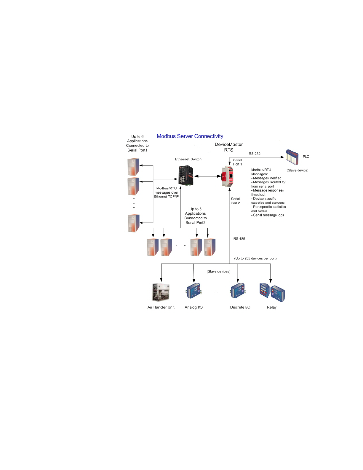
Modbus Server Application Overview
This section defines the software functionality for the Modbus Server application
and provides an overview of other Comtrol Modbus solutions (
The Modbus Server application was designed to provide enhanced connectivity for
O
PC servers and applications that require Modbus/RTU communications. While
standard gateways provide connectivity for only one application per serial port,
Modbus Server provides connectivity for up to six applications per serial port.
Modbus Server was designed to greatly en
Included are comprehensive device and port specific diagnostic web pages that
display status, message response timing, timeout, and other error counts, and
overall message statistics. A serial log is also included to provide message level
diagnosis.
Recommended Chassis
The following table lists the recommended DeviceMaster UP chassis based on
Modbus/RTU message throughput.
Page 9).
hance system maintenance capabilities.
Throughput 1-Port 2-Ports 4-Ports
Very High - Message rate of up to one message every
50 ms per port (20 messages per port per second)
High - Message rate of up to one message every 100
ms per port (10 messages per port per second)
Medium - Message rate of up to one message every
200 ms per port (5 messages per port per second)
Low - Message rate of up to one message every 500 ms
per port (2 messages per port per second)
Very Low - Message rate of up to one message every
second per port (1 message per port per second)
Latency
Transmit (From application to device) 2-10 ms (*)
Receive (From device to application 2-10 ms (*)
(*) = Based on one Ethernet TCP/IP connection per serial port running in a
normal uncongested system. The maximum overall latency will increase as the
number of Ethernet TCP/IP connections increase.
Note: T
hese estimates are based on a Modbus/RTU request and/or response
message size of 20 bytes. Actual throughput will vary depending on message
size and system requirements.
XX
XX X
XX X
XX X
XX X
DeviceMaster Modbus Server User Guide: 2000535 Rev. C Modbus Server Application Overview - 5
Page 6

Terms and Definitions
Terms and Definitions
This table provides Modbus Server definitions.
Term Definition
What is Modbus?
Master (or Client) Mode
Slave (or Server)
Modbus/RTU
Polling
Sockets
DeviceMaster DeviceMaster RTS or DeviceMaster UP.
The method of operation when a DeviceMaster or an
application is operating as a Master or the message
originator.
The method of operation when a DeviceMaster or an
application is operating as a Slave or the message
receiver.
The standard Modbus messages, in hexadecimal
format, that are typically transmitted over serial lines
but can also be transmitted over other communication
methods such as wireless or Ethernet TCP/IP socket
connections.
Note: Modbus/RTU over Ethernet TCP/IP is not the
same as Modbus/TCP.
The process where an application requests data on a
continual basis. In this operation the Master sends the
request messages while the Slave responds to the
messages.
The method used to communicate between devices
while communicating over Ethernet TCP/IP.
Modbus/RTU (Supported by Modbus Server)
Modbus/RTU is native Modbus in hexadecimal format. These are the base Modbus
messages that contain simple read and write requests. The format is as follows:
Where:
• The terms Master or Client are used to
• The terms Slave or Server are used to identify the devices responding to the
message.
Modbus/RTU is us
• Serial port connectivity. RS-485 is th
are also used.
• Ethernet TCP/IP socket connections. This is not the same as Modbus/TCP
(please see next section), but does provide a very simple method of interfacing
to remote devices. It is used by many applications and some OPC servers.
Note: This communication method is not used by PLCs.
ed for:
identify the sender of the message.
e most common, but RS-232 and RS-422
6 - Modbus Server Application Overview DeviceMaster Modbus Server User Guide: 2000535 Rev. C
Page 7

Modbus/TCP (Not supported by Modbus Server)
Modbus/TCP (Not
supported by Modbus
Server)
Modbus/TCP is an Ethernet network based protocol that contains a Modbus/RTU
message, with the exception of the 2 byte CRC. The Modbus/TCP message
contains a header with information designed to provide message identification and
routing information. The format is as follows:
Where:
• The terms Master or Client are used to
identify the sender of the message.
• The terms Slave or Server are used to identify the devices responding to the
message.
• Modbus/TCP messages are typically sent to and received on a defined
Ethernet TCP/IP socket of 502.
• Modbus/TCP implementations provide more capability, but also require more
processing than simpler Modbus/RTU implementations.
Modbus/TCP is used for connecting advanc
ed Ethernet based devices, such as
PLCs, HMIs, SCADA Systems, and most OPC Servers to:
• Other Ethernet devices supporting Modbus/TCP.
• Remote serial Modbus/RTU devices through gateways (such as the
DeviceMaster UP).
• Remote serial or Ethernet TCP/IP ASCII devices through a gateway (such as
the DeviceMaster UP).
Note: Refer to the DeviceMaster UP for Modbus/TCP functionality.
Modbus Server Functionality
The Modbus Server application provides the following functionality:
• Supports Modbus/RTU over Ethernet TCP/IP connections to the
corresponding serial port through intelligent Modbus message handling and
routing.
• Supports only Modbus/RTU over Ethernet TCP/IP connections to a serial port.
Note: For Modbus/TCP functionality, refer the DeviceMaster UP
• Supports up to six Ethernet TCP/IP connections to each serial port.
- One TCP/IP connection can be created with the Connect To connection
method.
-The Listen connection method accepts up to five or six connections,
depending if the Connect To connection is active.
• Supports up to 255 Modbus devices per port. Both valid, (1-247), and reserved,
(248-255), device Ids are supported.
• Modbus/RTU specific message handling:
- CRC verification of all messages received on the TCP/IP and serial
interfaces.
- Timing out of responses from slave Modbus/RTU devices.
- Broadcast message handling on connected port only.
.
DeviceMaster Modbus Server User Guide: 2000535 Rev. C Modbus Server Application Overview - 7
Page 8
Modbus Server Functionality
• System monitoring to ensure gateway operation:
- Gateway busy.
- Application message time-outs.
• Advanced diagnostics web pages:
- Modbus/RTU device specific statistics and status. Up to 255 Modbus/RTU
devices per port can be monitored simultaneously.
- Serial port specific statistics, response timing, and status.
- Serial port message logging.
• Combined with a serial port redirector, such as the Comtrol Secure Port
Redirector, which can support up to six COM port connections to each serial
port.
8 - Modbus Server Application Overview DeviceMaster Modbus Server User Guide: 2000535 Rev. C
Page 9
Other Comtrol Modbus Solutions
Comtrol provides several other Modbus solutions other than Modbus Server that
include:
• Modbus Router
•
Modbus/TCP
Other Comtrol Modbus Solutions
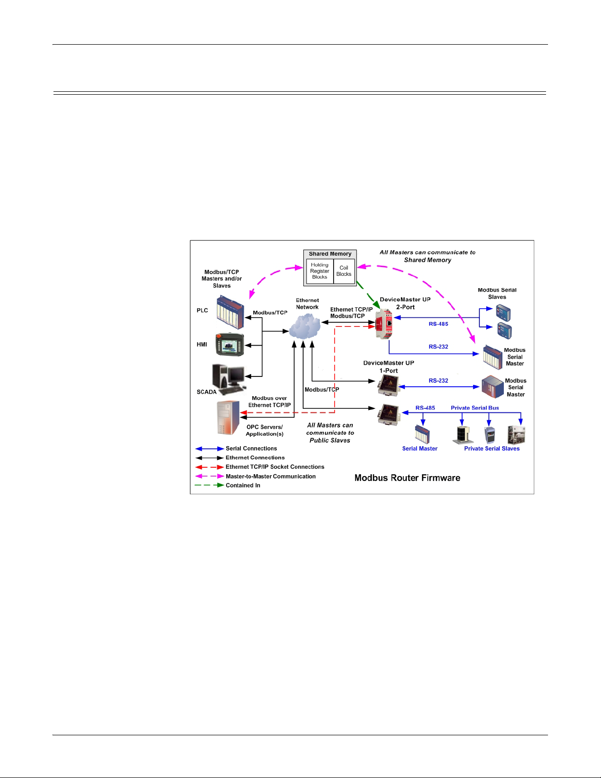
Modbus Router Modbus Router firmware was developed to prov
Modbus connectivity from a wide variety of Modbus masters to a wide variety of
local and remote Modbus slaves. Advanced features include master-to-master
communication, private serial bus connectivity, write protection, and device ID
aliasing. With simplified configuration pages and advanced routing, Modbus
Router provides unmatched Modbus connectivity.
ide innovative network-wide
Modbus Router firmware supports the
following controllers:
• Modbus/TCP masters
•
Modbus/RTU and Modbus/ASCII serial masters
• Modbus/RTU and Modbus/ASCII over Ethernet TCP/IP masters
• Modbus Router firmware supports the following devices:
• Modbus/TCP slaves
• Modbus/RTU and Modbus/ASCII serial slaves
With additional gateways, both remote Modbus serial slaves and raw/ASCII
devic
es Modbus Router firmware is recommended in installations that require:
• Local (directly attached) Modbus master
and/or slave connectivity
• No local raw/ASCII device connectivity
• Automatic Modbus protocol translations (if needed)
• Connectivity to remote Modbus slave(s) and/or raw/ASCII device(s)
• Connecting single or multiple Modbus masters to the slave device(s)
DeviceMaster Modbus Server User Guide: 2000535 Rev. C Modbus Server Application Overview - 9
Page 10
Modbus/TCP - Multiple Modbus Master and Slave Types, Serial and Ethernet Raw/ASCII Devices
• Master-to-Master connectivity (via Shared Memory subsystem)
• Isolation of serial Modbus slaves (via Private Serial Bus connectivity)
• Write protection of serial Modbus slaves
• Modbus Device ID conflict resolution
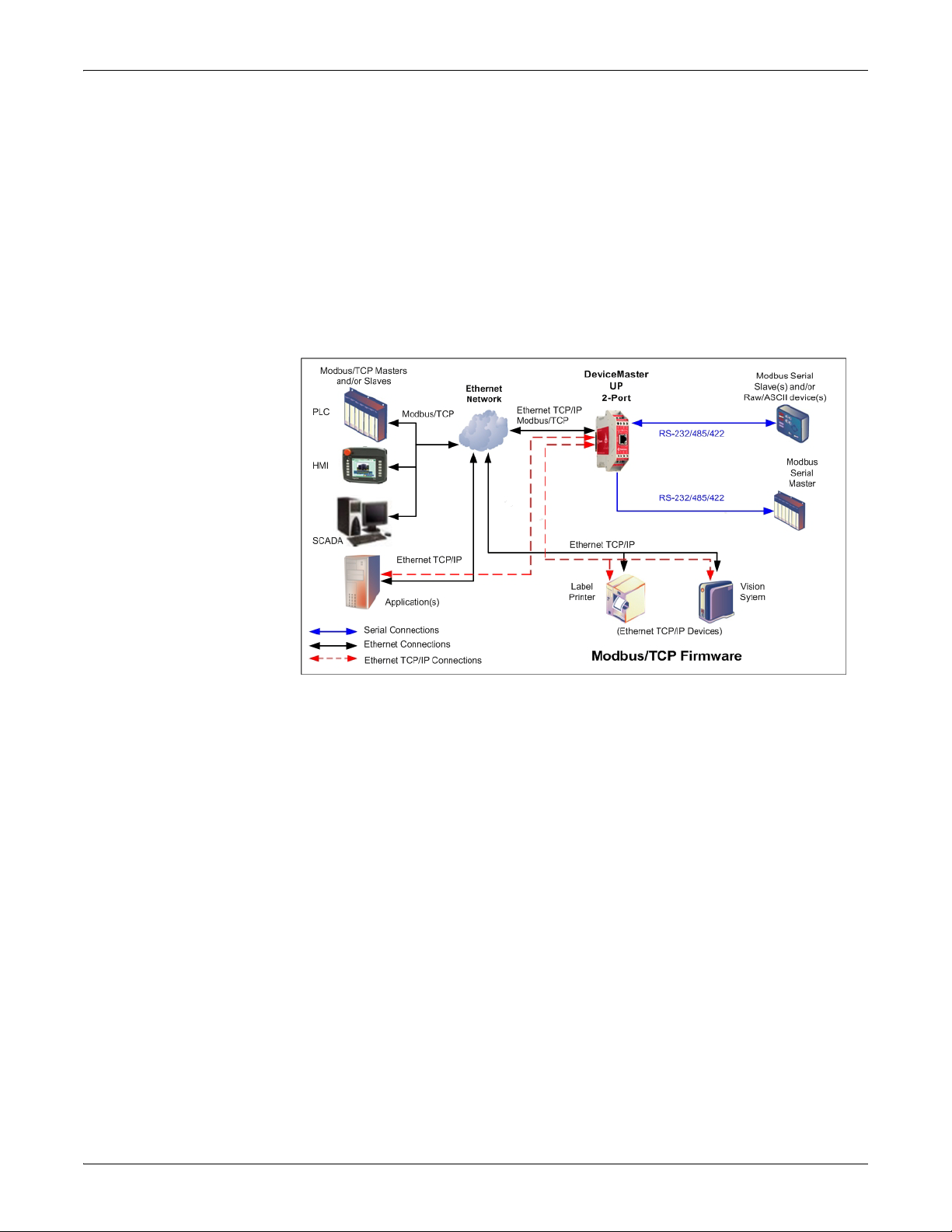
Modbus/TCP Multiple Modbus
Master and Slave
Types, Serial and
Ethernet Raw/ASCII
Devices
The Modbus/TCP firmware has been designed to provide great flexibility for
connecting both Modbus serial slaves and raw/ASCII devices to a variety of
Modbus controllers and applications.
Such advanced raw/ASCII options as filtering
, command/response mode, peer-topeer Modbus communications and simultaneous connections to multiple Modbus
controllers and/or Ethernet TCP/IP applications make the Modbus/TCP firmware
the flagship of all Modbus to raw/ASCII gateways.
Modbus/TCP firmware supports the
following controllers:
• Modbus/TCP masters and slaves
•
Modbus/RTU and Modbus/ASCII serial masters and slaves
• Applications over Ethernet TCP/IP connections (raw/ASCII only)
Modbus/TCP firmware supports the following devices:
• Raw/ASCII devices, both serial and Ethernet T
CP/IP, such as barcode
scanners, vision systems, RFID readers, weigh scales, encoders and printers
• Modbus/RTU and Modbus/ASCII serial slaves
• Modbus/TCP firmware is recommended in installations that require:
• Connectivity to serial and/or Ethernet TCP/IP raw/ASCII devices
• Connectivity to Modbus/RTU and/or Modbus/ASCII serial devices
• Connectivity from single or multiple Modbus masters and/or applications to
the devices
• Automatic Modbus protocol translations (if needed)
10 - Modbus Server Application Overview DeviceMaster Modbus Server User Guide: 2000535 Rev. C
Page 11

Installation Overview
Hardware Installation
Documents
Web
DeviceMaster UP Installation and
Configuration Guide
DeviceMaster UP Hardware
Installation and Configuration
Use this section to locate software and installation documentation for the
DeviceMaster UP to quickly install and configure Modbus Server.
An installation follow
1. Connect the DeviceMaster UP to
the network.
If necessary, use the appropriate
hardware installation document
for your DeviceMaster UP.
2. Install PortVision DX. You can
refer to the PortVision DX
Overview subsection to locate
PortVision DX and install it
easily.
3. Configure the DeviceMaster UP network settings using PortVision DX
(Configuring the Network Settings
4. You must upload the Modbus Server firmware into the DeviceMaster UP
using PortVision DX (Uploading Modbus Server
5. Configure the port characteristics using the DeviceMaster UP embedded web
page (Embedded Web Pages
6. Optionally, install the secure COM port redirector if you require COM port
support (Installing the Serial Port Redirector (Optional)
7. Connect any serial device or devices using the appropriate hardware
installation document for your DeviceMaster UP (table, above).
s these basic steps.
on Page 15).
on Page 18).
on Page 25).
on Page 19).
PortVision DX Overview
Use PortVision DX to identify, configure, update, and manage the DeviceMaster
UP on the following operating systems:
• Windows XP
•
Windows Server 2003
• Windows Vista
• Windows Server 2008
• Windows 7
• Windows Server 2012
• Windows 8/8.1
PortVision DX requires that you connect
to the same network segment as the Windows host system if you want to be able to
scan and locate it automatically during the configuration process.
Before installing PortVision DX, consider the following:
• Use PortVision DX to upload firmware and apply changes to a DeviceMaster
that is on the same local network segment as the system on which PortVision
DX is installed. You cannot apply changes through PortVision DX to a
DeviceMaster that is not on the same local network segment.
the Comtrol Ethernet-attached product
DeviceMaster UP Modbus Server User Guide: 2000535 Rev. C Installation Overview - 11
Page 12
Installation Overview
• Use PortVision DX to monitor any DeviceMaster on the network. The
DeviceMaster does not have to be on the same local network segment as
PortVision DX for monitoring purposes.
Installing PortVision DX
PortVision DX requires that you connect the DeviceMaster UP to the same
network segment as the Windows system during the configuration process.
1. If necessary, download the latest version of PortVision DX from
ftp://ftp.comtrol.com/dev_mstr/portvision_dx/
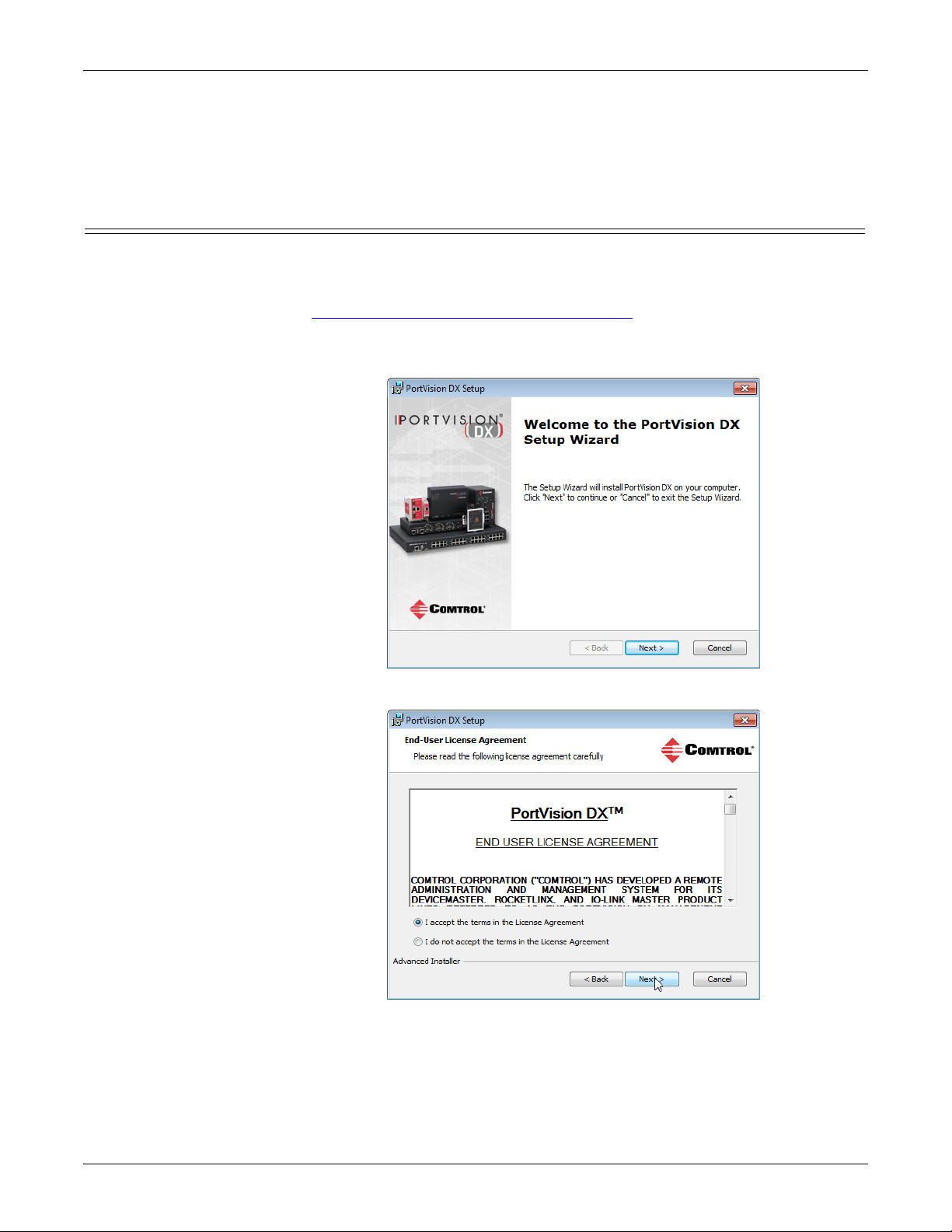
2. Execute the PortVision_DX_[version].msi file.
3. Click Next on the Welcome screen.
.
4. Click I accept the terms in the License Agreement and Next.
12 - Installation Overview DeviceMaster UP Modbus Server User Guide: 2000535 Rev. C
Page 13

Installing PortVision DX
5. Click Next or optionally, browse to a different location and then click Next.
6. Click Next to configure the shortcuts.
7. Click Install.
DeviceMaster UP Modbus Server User Guide: 2000535 Rev. C Installation Overview - 13
Page 14

Installation Overview
8. Depending on the operating system, you may need to click Ye s to the Do you
want to allow the following program to install software on this computer?
query.
9. Click Launch and Finish in the last installation screen.
10. Click the Scan button in the Toolbar so that PortVision DX locates the
DeviceMaster UP.
Note: PortVision DX locates all DeviceMaster models, including: the
DeviceMaster 500, DeviceMaster LT, DeviceMaster PRO, DeviceMaster
RTS, DeviceMaster Serial Hub, and DeviceMaster UP.
14 - Installation Overview DeviceMaster UP Modbus Server User Guide: 2000535 Rev. C
Page 15

Configuring the Network Settings
Default Network Settings
IP address:
192.168.250.250
Subnet mask:
255.255.0.0
Gateway address:
192.168.250.1
11. Select the products for which you want to scan. If you do not have any
RocketLinx managed switches or IO-Link Masters it saves scanning time if
you do not scan for them..
Note: If the Comtrol Ethernet-attached product is not on the local segment and it
has been programmed with an IP address, it will be necessary to manually
add the Comtrol Ethernet-attached product to PortVision DX.
12. Go to Step 5
in the next section, Configuring the Network Settings, to program
the DeviceMaster UP network settings.
If you need additional information about PortVision DX, refer to the Help system.
Configuring the Network Settings
DeviceMaster UP Modbus Server User Guide: 2000535 Rev. C Installation Overview - 15
Use the following procedure to change the default network settings on the
DeviceMaster UP for your network.
Note: T
echnical Support advises configuring one new DeviceMaster UP at a time
to avoid device driver configuration problems.
The following procedure shows how to configure a single DeviceMaster
UP
connected to the same network segment as the Windows system.
1. If you have not done so, install PortVision DX (Installing PortVision DX on
Page 12).
2. Start PortVision DX using the PortVision DX desktop shortcut or from the Start
button, click Programs > Comtrol, > PortVision DX.
3. If this is the first time you have opened PortVision DX, click the Scan button in
the Toolbar.
4. Select the products for
which you want to scan. If
you do not have any
RocketLinx managed
switches or IO-Link
Masters it saves scanning
time if you do not scan for
them..
Note: If the Comtrol Ethernet-
attached product is not
on the local segment and
it has been programmed
with an IP address, it
will be necessary to
manually add the
Comtrol Ethernet-attached product to PortVision DX.
Page 16

Installation Overview
5. Highlight the DeviceMaster for which you want to program network
information and open the Properties screen using one of these methods.
• Double-click the DeviceMaster in the Device Tree or Device List pane.
• Highlight the DeviceMaster in the Device Tree or Device List pane and click
the Properties button.
• Right-click the DeviceMaster in the Device Tree or Device List pane and
click Properties in the popup menu
• Highlight the DeviceMaster, click the Manage menu and then Properties.
Note: See the PortVision DX Help system for information about using
PortVision DX.
16 - Installation Overview DeviceMaster UP Modbus Server User Guide: 2000535 Rev. C
Page 17

Configuring the Network Settings
6. Optionally, rename the DeviceMaster UP in the Device Name field.
Note: The MAC address and Device Status fields are automatically populated and
you cannot change those values.
7. Optionally, enter the serial number, which is on a label on the DeviceMaster.
8. If necessary, you can change the Detection Type.
• REMOTE means that the DeviceMaster is not connected to this segment of
the network and it uses IP communications, not MAC communications.
• LOCAL means that the DeviceMaster is on this local network segment and
uses MAC communications. An IP address is not required but Technical
Support recommends using an IP address.
9. Change the DeviceMaster network properties as required for your site.
• Do not select this option to run the DeviceMaster in MAC mode. The
DeviceMaster does not support MAC mode.
• To use the DeviceMaster with DHCP, click DHCP IP, and make sure that
you provide the MAC address of the device to the network administrator.
Make sure that the administrator reserves the IP address, subnet mask
and gateway address of the DeviceMaster in the DHCP server.
• To program a static IP address, click Static IP and enter the appropriate
values for your site.
10. Click Apply Changes to update the network information on the DeviceMaster.
11. Click Close to exit the Properties window.
DeviceMaster UP Modbus Server User Guide: 2000535 Rev. C Installation Overview - 17
Page 18

Installation Overview
Uploading Modbus Server
Use this section to upload Modbus Server on the DeviceMaster UP using
PortVision DX.
1. Make sure that you download the latest Modbus Server version.
2. Execute the .msi to unpackage the Modbus Server firmware file.
3. If necessary, open PortVision DX > Start/Programs > Comtrol > PortVision DX
> P
4. Rig
click Advanced > Upload Firmware, browse to the Modbus Server .cmtl fi
then
o
rtVision DX or use the desktop shortcut.
ht-click the DeviceMaster or DeviceMasters for which you want to load,
le and
click Open.
5. Click Ye s to the Upload Firmware message that warns you that this is a
sensitive process.
18 - Installation Overview DeviceMaster UP Modbus Server User Guide: 2000535 Rev. C
Page 19

It may take a few moments for the firmware to upload onto the device. The
device will reboot itself during the upload process.
6. Click Ok to the advisory message about waiting to use the device until the
status reads ON-LINE. In the next polling cycle, PortVision DX updates the
List View pane and displays the new Modbus Server version.
Installing the Serial Port Redirector (Optional)
If your environment requires COM port support, you can install the Comtrol serial
port redirector using the following procedure.
1. If you have not done so, download the serial port redirector.
2. Execute the .msi file and click Next.
Installing the Serial Port Redirector (Optional)
3. Click I accept the terms in the License
Agreement and then click Next.
4. If desired, Browse to another
installation location or click Next.
DeviceMaster UP Modbus Server User Guide: 2000535 Rev. C Installation Overview - 19
Page 20

Installation Overview
5. Click Next to the Configure Shortcuts screen.
6. Click Install.
7. Click Finish.
20 - Installation Overview DeviceMaster UP Modbus Server User Guide: 2000535 Rev. C
Page 21

Configuring Port Redirector COM Ports
Use the following procedures to:
• Add a DeviceMaster UP port
•
Configure the port for the secure port redirector
If necessary, refer to the secure port redirector help
Configuring Port Redirector COM Ports
system for more information.
Adding a Secure
Po
rt
Use the following procedure to add a secure port or ports.
Note: You must have enabled the security feature in SocketServer and have the IP
address and TCP port numbers and enabled the TCP Connection for each
port before performing the following procedure.
1. If necessary, open the Secure Port Redirector, click Start, Programs, Secure Port
Redirector, and Secure Port Redirector.
2. Click Port and Add.
3. Select an available COM port in the
Virtual serial port drop list.
4. Click Client or Server depending
on the COM port requirements.
5. Enter the Remote IP address of the
DeviceMaster UP.
6. Enter the TCP port number for
which you want to communicate on
the DeviceMaster UP.
7. Click Ok.
8. Repeat Step 2
for each port that you
want to use as a secure COM port.
DeviceMaster UP Modbus Server User Guide: 2000535 Rev. C Installation Overview - 21
Page 22

Installation Overview
Configuring the Secure COM Port
Use the following procedure to configure the port.
1. Double-click the port that you want to configure.
2. Optionally click the Connection
Settings tab, click Auto-reconnect when
connection is broken, set the
Reconnect interval, set Cache data
when the connection is broken,
and then Ok.
3. Click the SSL Security tab and then click Use SSL for connection to remote side.
22 - Installation Overview DeviceMaster UP Modbus Server User Guide: 2000535 Rev. C
Page 23

Configuring the Secure COM Port
4. Click the Settings tab and select the appropriate serial port settings.
5. Optionally, click the Extra Strings tab and enter the appropriate values.
6. Click OK to save the settings for the DeviceMaster UP.
7. Repeat the above procedure for each port that you want to use as a secure
COM port.
8. Close the Secure Port Redirector window when you are done.
You are now ready to connect the serial devices to the DeviceMaster UP ports.
DeviceMaster UP Modbus Server User Guide: 2000535 Rev. C Installation Overview - 23
Page 24

Installation Overview
24 - Installation Overview DeviceMaster UP Modbus Server User Guide: 2000535 Rev. C
Page 25

Embedded Web Pages
All configuration and status information is provided through embedded web pages
for Modbus Server.
Note: T
For firmware installation and setup information, see
Page 11 or the PortVision DX help system.
This section discusses the following:
• Configuration overview (below)
• Server Configuration (Main) Page
• Serial Interface Configuration Page
• Edit Port Configuration Page
• Edit Network Configuration Page
See the Embedded Diagnostic and Statistics Pages (Page 33) section for
information about locating diagnostic and
Configuration Overview
he latest Modbus Server firmware must be installed before you can
configure network or serial/socket port characteristics.
Installation Overview on
on Page 26
on Page 27
on Page 28
on Page 31
statistics for Modbus Server.
The following overview shows how to access the DeviceMaster Server
Configuration embedded web page and configure serial device interfaces.
Note: If you have not configured the network information into the DeviceMaster
during initial setup, you must configure the network information before
configuring port characteristics.
1. From PortVision DX, highlight the
DeviceMaster that you want to configure
and select Web page.
2. Optionally, enter the IP address of the
device in the Address box of your web
browse.
3. Select Serial Interface Configuration.
4. Select the appropriate port to access the
Edit Port Configuration page for that port.
5. Change the serial port configuration
properties as required for your site.
DeviceMaster Modbus Server User Guide: 2000535 Rev. C Embedded Web Pages - 25
Page 26

Server Configuration (Main) Page
Server Configuration (Main) Page
Access the main DeviceMaster web page (Server
Configuration) from P
IP address of the DeviceMaster in the Address
box of your web browser.
The Serv
software version and current network
configuration for the DeviceMaster.
In addition, the Server Configuration pa
to the configuration, statistics, and diagnostics
pages, which are discussed in the table below.
Sof
IP Config
IP Address
IP Netmask
IP Gateway
Serial Interface
Configuration
Communication
Statistics
Display Serial
Logs
Configure
Network
Display All
Known
Modbus/RTU
Devices
Reboot Reboots the DeviceMaster.
er Configuration page displays the
Server Configuration Page
Modbus Server firmware
tware
version currently running on
the DeviceMaster.
Type of IP configuration
currently in use (static or
DHCP).
IP address, netmask, and
gateway configured in the
DeviceMaster.
Opens the Serial Interface
Configuration Page (Page 27),
which provides an overview of
the serial interface settings and
provides access to the Edit Port
Configuration page for serial
port configuration on the
selected port.
Opens the Serial Interface
Communications Statistics
Page (Page 27), which contains
serial interface and application
connection statistics.
Opens the Serial Interface Logs
Page (Page 36), which contains
the statistics and error
reporting information for each
port.
Opens the Edit Network
Configuration Page (Page 31),
which can be used to modify
DeviceMaster network
configuration after initial
configuration using PortVision
DX.
Opens the Known Modbus/
RTU Device List Web Page
(Page 33), which displays all
known Modbus/RTU device
attached to all serial ports.
ortVision DX or enter the
ge links
26 - Embedded Web Pages DeviceMaster Modbus Server User Guide: 2000535 Rev. C
Page 27

Serial Interface Configuration Page
The Serial Interface
Configuration p
provides:
• Links to the following
pa
ges:
- Server
Configuration
(Main) Page (Page
26)
- Serial Interface
Communications
Statistics Page
(Page 34)
- Serial Interface
Logs Page (Page
36)
- Known Modbus/
RTU Device List
Web Page (Page 33)
for all ports or a
specific port.
Clicking the
Display Devices
(all) link or the
Display Devices for
a specific port.
• Access to the Edit Port
Configuration page for
each port (Port #)
• An overview of serial
device configuration
settings for each port,
which displays the
current settings
Note: The Application
TCP Connection
Status displays the
Remote
Connections.
Up to six active TCP/IP connections for each serial port may be displayed at
one time.
To change any settings for a port, select the corresponding Po
age
Serial Interface Configuration Page
rt # link, which opens
DeviceMaster Modbus Server User Guide: 2000535 Rev. C Embedded Web Pages - 27
Page 28

Edit Port Configuration Page
Select the appropriate serial
port number to configure the
serial port characteristics.
the Edit Port Configuration page.
Edit Port
Confi
guration Page
Use the Edit Port Configuration page to change a serial port’s configuration
parameters.
To access the Edi
t Port Configuration page, select the appropriate port number
link (for example, Port 1) on the Serial Interface Configuration page.
Use the Seria
l Configuration area of the Edit Port Configuration page to configure
serial port characteristics for the device that you plan on connecting to the port.
28 - Embedded Web Pages DeviceMaster Modbus Server User Guide: 2000535 Rev. C
Page 29

Name Value(s) Description
Serial Configuration
All models, except 2-port
models:
• RS-232 (default)
•RS-422
•RS-485
Mode
2-port models:
Selectable serial mode of communications.
• RS-232 (default)
•RS-422
• RS-485_2-wire
• RS-485 4-wire Master
• RS-485 4-wire Slave
300, 600, 1200, 2400,
Baud Rate
4800, 9600, 19200, 38400
(default), 57600, 115200,
Selectable serial port baud rates.
230400
None (default)
Parity
Even
Selectable parity values.
Odd
Data Bits 5, 6, 7, 8 (default) Selectable data bit values.
Stop Bits 1(default) or 2 Selectable stop bit values.
None (default)
Flow
RTS/CTS
XON/XOFF
Selectable flow control values.
Half-Duplex
Receive time-outs between packets in
milliseconds. This is the maximum spacing
between received bytes allowed before
Rx Timeout Between
Packets
0-65535
(default = 50)
Modbus/RTU messages/responses received
over both the serial and Ethernet TCP/IP
interface are expected to be complete.
Note: If this value is set too low, incomplete
and/or invalid Modbus/RTU
messages may be incorrectly detected.
Duplicate Serial
Configuration For All
Ports
N/A
If selected, will apply the serial port
configuration to all serial ports.
Modbus/RTU Protocol Settings
Device Response
Timeout
0 to 65535 ms.
(Default=1000 ms)
The maximum allowable time for a slave
Modbus/RTU to respond to a message before
the message is considered timed out.
Edit Port Configuration Page
DeviceMaster Modbus Server User Guide: 2000535 Rev. C Embedded Web Pages - 29
Page 30

Edit Port Configuration Page
Name Value(s) Description
Discard Rx Packets
With Errors
Duplicate Modbus/
RTU Protocol for All
Ports.
Application TCP Connection Configuration
Enable
Listen
Listen Port
Connect to Mode
Connect Port
Connect IP Address
Disconnect Mode
Idle Timer
On/Off
(Default = On)
N/A
On/Off
(Default = On)
On/Off
(Default = On)
1-65535
Default:
Port 1=8000
Port 2=8001
Port 3=8002
..
..
Port N =800N -1
Never
Connect-Always
(Default = Never)
1 to 65535
(Default=0)
Standard IP address
format:
xxx.xxx.xxx.xxx
Never
Idle
(Default = Never)
1 to 65535
(Default=0)
If selected, the DeviceMaster will drop all
packets received with parity, framing, or
overrun errors.
Note: Modbus/RTU messages with invalid
CRCs will always be discarded
independent of this setting.
If selected, will apply the Modbus/RTU
protocol settings to all serial ports.
If selected, this TCP/IP socket interface will
be enabled.
If selected, the TCP/IP socket interface will
listen for a connection at the specified Listen
Port.
If Enable and Listen are both selected, allows
acceptance of:
Up to six connections from external
applications if there is no active Connect-to
connection.
Up to five connections if there is an active
Connect-to connection.
If Enable is selected, this setting determines
how to connect to an application.
If Never, do not attempt to make a connection.
If Connect-Always: Always attempt to
maintain a connection to the application at
Connect IP Address and Connect Port.
Socket port to connect to. Used in conjunction
with Connect to Mode and Connect IP Address.
IP Address of application to create a
connection. Used in conjunction with Connect
to Mode and Connect Port.
Mode on which to disconnect from the
application.
Never – Will not disconnect when
connection(s) are idle. (Typically used in
Listen and Connect-Always modes.)
Idle – Utilizes the
Idle Timer t
o determine
when to close the connection.
If the Disconnect Mode is set to Idle, the idle or
inactivity time when the connection(s) will be
closed.
30 - Embedded Web Pages DeviceMaster Modbus Server User Guide: 2000535 Rev. C
Page 31

Edit Network Configuration Page
You can use the Edit Network Configuration page to change the DeviceMaster
network configuration after using PortVision DX for initial network configuration.
Use the following procedure to chan
1. Select the IP configuration type (Use DHCP or Use St
2. If you select Use Static configuration below, enter a valid IP address, subnet
mask, and IP gateway for your network. The network information is
programmed into the DeviceMaster after applying the changes and rebooting
the device. If necessary, see your network administrator for a valid IP address.
Note: The DeviceMaster family default IP address is 192.168.250.250, default
subnet mask is 255.255.0.0, and the default IP gateway is
192.168.250.1.
3. Select Save or Undo Changes to close the page.
4. If you selected Save, select Reboot to program the network information into the
DeviceMaster or Continue if you want to reboot later.
Note: Changed network settings will not take affect until the DeviceMaster is
rebooted.
Edit Network Configuration Page
ge the network configuration.
atic configuration below:).
DeviceMaster Modbus Server User Guide: 2000535 Rev. C Embedded Web Pages - 31
Page 32

Edit Network Configuration Page
32 - Embedded Web Pages DeviceMaster Modbus Server User Guide: 2000535 Rev. C
Page 33

Embedded Diagnostic and Statistics Pages
This section discusses embedded diagnostic and statistics web pages for Modbus
Server.
Known Modbus/RTU Device List Web Page
The Known Modbus/RTU Device List page provides device specific status and
statistics for each device on one or all ports.
Know Modbus/RTU Device List Page
evice ID Unit identifier associated with this device.
D
Status of device:
Active?
Tx Requests Number of Modbus messages transmitted to this device.
Rx Responses Number of Modbus responses received from this device.
Timeouts Number of response time-outs associated with this device.
Last Rsp Time The last response time from Modbus/RTU device.
Avg Rsp Time The average response time from Modbus/RTU device.
Min Rsp Time The minimum response time from Modbus/RTU device.
Max Rsp Time The maximum response time from Modbus/RTU device.
Invalid Responses Number of invalid responses received from this device.
DeviceMaster Modbus Server User Guide: 2000535 Rev. C Embedded Diagnostic and Statistics Pages - 33
• Ye s means that the last request received a valid
response and did not time out.
• No means that the last request timed out.
Page 34

Serial Interface Communications Statistics Page
Serial Interface Communications Statistics Page
Where the following definitions apply:.
Counter Name Description
TX Byte Count (To Device) Number of bytes transmitted out the serial port.
TX Message Count Number of messages transmitted out the serial port.
RX Byte Count (From Device) Number of bytes received on the serial port.
RX Response Count Number of responses received on the serial port.
34 - Embedded Diagnostic and Statistics Pages DeviceMaster Modbus Server User Guide: 2000535 Rev. C
Page 35

Serial Interface Communications Statistics Page
Counter Name Description
Parity Error Count
Framing Error Count
Number of parity errors received on the serial port. Typically occurs
due to an incorrect parity setting.
Number of framing errors received on the serial port. Typically
occurs due to an incorrect baud rate or stop bit setting.
Number of overrun errors received on the serial port.. Typically
Overrun Error Count
occurs to one of the following: incorrect flow control, incorrect baud
rate, incorrect data size, or incorrect stop bit setting.
Number of invalid RTU device responses. These responses can be
caused by the following:
Invalid RTU Device Responses
• Message received after the timeout period. This may require
increasing the Modbus/RTU Device Response Timeout.
• Incorrect device ID in response message.
• Incorrect function code in response message.
RTU Device Timeouts
The number of RTU device time-outs that occurred when there was
no response for a Modbus message.
The status of the last device response:
• Ye s – The last message received a valid response from a device
Last Device Active?
connected to the serial port.
• No – The last message did not receive a valid response from a
device connected to the serial port
The number of times a device went from the inactive state, (not
Device Transitions Inactive to
Active
responding or no responses yet), to the active state (responding
correctly).
In a system with all devices responding correctly, this number will
typically equal the number of active devices.
The number of times a device went from the active state (responding
Device Transitions Active to
Inactive
correctly) to the inactive state (not responding correctly).
This number is intended to help identify the number times devices
respond intermittently.
Application Connection Statistics
TX Byte Count Number of bytes transmitted out of the TCP/IP connection(s).
TX Response Count (TO
application)
Number of responses transmitted out of the TCP/IP connection(s).
The number of responses that were intended to be transmitted out
Dropped TX Responses
the TCP/IP connection(s) but could not be and were dropped. This
typically occurs when one or more connections close unexpectedly.
RX Byte Count Number of bytes received on the TCP/IP connection(s).
RX Message Count (From
Application)
Dropped RX Messages Due to
Congestion
Number of messages received on the TCP/IP connection(s).
The number of messages that were dropped to the gateway being
overly congested. This typically occurs when the application(s) send
messages faster than the device(s) can respond.
The number of messages from the application(s) that were dropped
Dropped Invalid or Incomplete
RX Messages
to:
• Containing an invalid Modbus/RTU message format.
• Containing an incomplete Modbus/RU message.
DeviceMaster Modbus Server User Guide: 2000535 Rev. C Embedded Diagnostic and Statistics Pages - 35
Page 36

Serial Interface Logs Page
Counter Name Description
Dropped RX Messages Due to
In
valid CRCs
Number of messages from the application(s) that were dropped due
to an invalid Modbus/RTU CRC.
TX Byte Count (To Device) Number of bytes transmitted out the serial port.
Serial Interface Logs Page
The following page displays the serial message transmitted and received during
normal operation.
The format is as follows:
Pkt(N): ddd:hh:mm:ss.mss Rx/Tx:(data packet)
Where:
ddd Da
hh Hours sinc
mm Minutes since last
ss
mss Mi
(data) Mo
ys since last system restart
e last system restart
system restart
Seconds since last system restart
lliseconds since last system restart
dbus/RTU message data.
36 - Embedded Diagnostic and Statistics Pages DeviceMaster Modbus Server User Guide: 2000535 Rev. C
Page 37

Troubleshooting and Technical Support
This section contains troubleshooting information for your DeviceMaster. You
should review the following subsections before calling Technical Support because
they will request that you perform many of the procedures or verifications before
they will be able to help you diagnose a problem.
• <hyperlink-CrossReference>Trouble
• <hyperlink-CrossReference>General Troubleshooting on Page 38
• <hyperlink-CrossReference>Daisy-Chaining DeviceMaster 2E/4-Port Units on
Page 39
If you cannot diagnose the problem, you can contact <hyperlinkCrossReference>Technical Support on Page 40.
Troubleshooting Checklist
The following checklist may help you diagnose your problem:
• Verify that you are using the correct types of cables on the correc
and that all cables are connected securely.
Note: Most customer problems reported to Comtrol Technical Support are
• Isolate the DeviceMaster from the network by connecting the device directly to
a NIC in a host system.
shooting Checklist on Page 37
t connectors
eventually traced to cabling or network problems.
Model Connected to
1-Port Ethernet hub or NIC Standard 10/100 ETHERNET
1-Port Embedded Ethernet hub or NIC Standard RJ45 port (not labeled)
2-Port - 1E (All
models)
2-Port - 2E (All dual
Ethernet ports)
4-Port
• Verify that the Ethernet hub and any other network devices between the
system and the DeviceMaster are powered up and operating.
• Reset the power on the DeviceMaster and watch the PWR or Status light
activity.
PWR or Status LED Description
5 sec. off, 3 flashes, 5 sec. off, 3 flashes ... Redboot
5 sec. off, 4 flashes, 5 sec. off, 4 flashes ... SREC load failure.
5 quick flashes
10 sec. on, .1 sec. off, 10 sec. on .1 sec. off
...
Ethernet hub or NIC Standard 10/100
Ethernet hub or NIC Standard 10/100 - E1/E2
NIC Standard DOWN
Ethernet hub Standard UP
Ethernet
Cable
Connector Name
™ checksum failure.
The default application is starting
up.
The default application is running.
DeviceMaster Modbus Server User Guide: 2000535 Rev. C Troubleshooting and Technical Support - 37
Page 38

General Troubleshooting
• If the device has a power switch, turn the device’s power switch off and on,
while watching the LED diagnostics.
• If the DeviceMaster does not have a power switch, disconnect and reconnect
the power cord.
• Verify that the network IP address, subnet mask, and gateway is correct and
appropriate for the network. If IP addressing is being used, the system should
be able to ping the DeviceMaster.
• Verify that the IP address programmed into the DeviceMaster matches the
unique reserved IP configured address assigned by the system administrator.
• If using DHCP, the host system needs to provide the subnet mask and
gateway.
• Reboot the system and the DeviceMaster.
• If you have a spare DeviceMaster, try replacing the device.
General Troubleshooting
This table illustrates some general troubleshooting tips.
Note: Make sure that you have reviewed the <hyperlink-
CrossReference>Troubleshooting Checklist on Page 37.
General Condition Explanation/Action
Indicates that boot program has not downloaded to the
unit.
1. Reboot the system.
PWR or Status LED
flashing
2. Make sure that you have downloaded the most
current firmware for your protocol:
fttp://ftp.comtrol.com/html/up_main.htm
Note: If the PWR or Status LED is still flashing,
contact Technical Support.
PWR or Status LED not
lit
Cannot ping the device
through Ethernet hub
Cannot ping or connect
to the DeviceMaster
Indicates that power has not been applied or there is a
hardware failure. Contact Technical Support.
Isolate the DeviceMaster from the network. Connect
the device directly to the NIC in the host system (see
Page 37).
The default IP address is often not accessible due to the
subnet masking from another network unless 192.168 is
used in the network.
In most cases, it will be necessary to program in an
address that conforms to your network.
DeviceMaster
continuously reboots
when connected to some
Invalid IP information may also cause the switch or
router to check for a gateway address. Lack of a
gateway address is a common cause.
Ethernet switches or
routers
.
38 - Troubleshooting and Technical Support DeviceMaster Modbus Server User Guide: 2000535 Rev. C
Page 39

Daisy-Chaining DeviceMaster 2E/4-Port Units
The DeviceMaster 2E/4-port models with external power supplies follow the IEEE
specifications for standard Ethernet topologies.
When using the UP an
switch. When using the UP port only, it is a simple end node device.
The maximum number of daisy-chained DeviceMaster 2E/4 units, and the
maximum distance between u
determined by your own environment and the conformity of your network to these
standards.
Comtrol has tested with seven DeviceMaster 2E/4 units daisy-chained together
u
sing 10 foot CAT5 cables, but this is not the theoretical limit. You may experience
a performance hit on the devices at the end of the chain, so it is recommended that
you overload and test for performance in your environment. The OS and the
application may also limit the total number of ports that may be installed.
Following are some quick guidelines and URLs of additional information. Please
n
ote that standards and URLs do change.
• Ethernet 10BASE-T Rules
- The maximum number of repeater hops is four.
- You can use Category 3 or 5 twisted-pair 10BASE-T cables.
- The maximum length of each cable is 100m (328ft).
Note: Category 3 or 5 twisted pair cables look the same as telephone cables
but they are not the same. The network will not work if telephone
cables are used to connect the equipment.
• Fast Ethernet 100BASE-TX rules
- The maximum number of repeater hops is two (for a Class II hub). A Class
II hub can be connected directly to one other Class II Fast Ethernet hub. A
Class I hub cannot be connected directly to another Fast Ethernet hub.
- You must use Category 5 twisted-pair 100BASE-TX cables.
- The maximum length of each twisted-pair cable is 100m (328ft).
- The total length of twisted-pair cabling (across directly connected hubs)
must not exceed 205m (672ft).
Note: Category 5 twisted pair cables look the same as telephone cables but
they are not the same. The network will not work if telephone cables
are used to connect the equipment.
• IEEE 802.3 specification: A network using repeaters between communicating
stations (PCs) is subject to the “5-4-3” rule of repeater placement on the
network:
- Five segments connected on the network.
- Four repeaters.
- Three segments of the 5 segments can have stations connected. The other
two segments must be inter-repeater link segments with no stations
connected.
See http://www.optronics.gr/Tutorials/ethernet.htm
information.
Additional information may be found at http://compnetworking.about.com/
cs/ethernet1/ or by searching the web.
d DOWN ports, the DeviceMaster 2E/4 is classified as a
nits is based on the Ethernet standards and will be
Daisy-Chaining DeviceMaster 2E/4-Port Units
for more specific
DeviceMaster Modbus Server User Guide: 2000535 Rev. C Troubleshooting and Technical Support - 39
Page 40

Technical Support
Technical Support
It contains troubleshooting procedures that you should perform before contacting
Technical Support since they will request that you perform, some or all of the
procedures before they will be able to help you diagnose your problem. If you need
technical support, use one of the following methods.
Comtrol Contact Information
Downloads ftp://ftp.comtrol.com/html/up_modbus_server_main.htm
Web site http://www.comtrol.com
Phone 763.957.6000
40 - Troubleshooting and Technical Support DeviceMaster Modbus Server User Guide: 2000535 Rev. C
 Loading...