

Page 1

User Guide
Page 2

Trademark Notices
Document Number: 2000582 Rev. A
Microsoft and Windows are registered trademarks of Microsoft Corporation.
Other product names mentioned herein may be trademarks and/or registered trademarks of their respective
owners.
First Edition, August 27, 2014
Copyright © 2013-2014. Comtrol Corporation.
All Rights Reserved.
Comtrol Corporation makes no representations or warranties with regard to the contents of this document or
to the suitability of the Comtrol product for any particular purpose. Specifications subject to change without
notice. Some software or features may not be available at the time of publication. Contact your reseller for
current product information.
Page 3

Table of Contents
Chapter 1. Introduction........................................................................................................5
1.1. Installation and Configuration Overview ........................................................................................ 5
1.2. Locating the Latest Software and Documentation ........................................................................ 5
Chapter 2. Hardware Installation ......................................................................................7
2.1. Setting the Rotary Switch .................................................................................................................... 7
2.2. Mounting the IO-Link Master.............................................................................................................. 8
2.3. Connecting to the Network .................................................................................................................. 8
2.4. Connecting the Power ......................................................................................................................... 10
2.5. IO-Link Master LEDs ........................................................................................................................... 12
Chapter 3. Initial Configuration.......................................................................................13
3.1. Using PortVision DX ............................................................................................................................ 13
3.1.1. PortVision DX Overview ................................................................................................................ 13
3.1.2. Installing PortVision DX ................................................................................................................ 15
3.1.3. Programming the IP Address......................................................................................................... 17
3.2. Using the Web Interface...................................................................................................................... 19
3.3. Setting up Passwords .......................................................................................................................... 22
Chapter 4. Updating Images and Application Subassemblies...................................25
4.1. Images and Application Subassemblies Overview ....................................................................... 25
4.1.1. Images ............................................................................................................................................. 26
4.1.2. Application Subassemblies............................................................................................................. 26
4.2. Using PortVision DX to Update Software....................................................................................... 27
4.3. Using the Web Interface to Update Software ................................................................................ 28
4.3.1. Updating Images............................................................................................................................. 28
4.3.2. Updating Application Subassemblies ............................................................................................ 29
Chapter 5. IO-Link Port Configuration...........................................................................31
5.1. IO-Link Settings Configuration Page .............................................................................................. 31
5.1.1. Editing IO-Link Settings................................................................................................................ 32
5.1.2. IO-Link Settings Parameters......................................................................................................... 32
5.2. EtherNet/IP Settings Configuration Page ...................................................................................... 33
5.2.1. Editing EtherNet/IP Settings ........................................................................................................ 34
5.2.2. EtherNet/IP Settings Parameters ................................................................................................. 35
5.3. Modbus/TCP Settings Configuration Page.....................................................................................40
5.3.1. Editing Modbus/TCP Settings........................................................................................................ 41
5.3.2. Modbus/TCP Settings Parameters................................................................................................. 41
Chapter 6. Connecting Devices .........................................................................................45
Chapter 7. Using the Diagnostics Pages .........................................................................47
7.1. IO-Link Port Diagnostics .................................................................................................................... 47
7.2. EtherNet/IP Diagnostics ..................................................................................................................... 50
7.3. Modbus/TCP Diagnostics .................................................................................................................... 54
IO-Link Master 4-EIP User Guide: 2000582 Rev. A Table of Contents - 3
Page 4

Table of Contents
Chapter 8. Troubleshooting and Technical Support ...................................................57
8.1. Troubleshooting.................................................................................................................................... 57
8.2. Contacting Technical Support .......................................................................................................... 58
8.3. Using Log Files...................................................................................................................................... 59
8.3.1. View a Log File ............................................................................................................................... 59
8.3.2. Clear a Log File............................................................................................................................... 59
8.3.3. Export a Log File ............................................................................................................................ 60
4 - Table of Contents IO-Link Master 4-EIP User Guide: 2000582 Rev. A
Page 5

Chapter 1. Introduction
This document provides installation, configuration, and embedded web interface information for the IO-Link
Master 4-EIP. The embedded web interface provides a platform so that you can easily configure, review
diagnostic pages, and access advanced features, such as: uploading the latest IO-Link Master images or
applications, and set up user accounts with different user levels and passwords.
Detailed information interface specifications are located in the following IO-Link Master Reference Manuals:
• IO-Link Master EtherNet/IP Reference Manual
• IO-Link Master Modbus/TCP Reference Manual
1.1. Installation and Configuration Overview
IO-Link Master installation includes the following procedures.
1. Install the IO-Link Master hardware (Page 7).
2. If necessary, configure the IP address using PortVision DX or the embedded web page (Page 13
3. Configure the IO-Link ports using the embedded web page (Page 5
4. Connect the IO-Link devices (Page 45
).
).
).
1.2. Locating the Latest Software and Documentation
You can use the links in this table to locate the latest images, application subassemblies, utilities, and
documentation. For detailed information about images or application subassemblies and updating IO-Link
Master, see
4.3.2. Updating Application Subassemblies on Page 29.
Latest Images
Application Base
FPGA
U-Boot Bootloader
System uImage (Primary/Backup)
Latest Application Subassemblies
Application Manager
Configuration Manager
Discovery Protocol
EtherNet/IP
IO-Link Master 4-EIP User Guide: 2000582 Rev. A Chapter 1. Introduction - 5
Page 6

Locating the Latest Software and Documentation
Event Log
IO-Link Driver
Web User Interface
Latest Configuration Utility
PortVision DX supports Windows XP
through Windows 8.1
Latest Images
This is a configuration and
management utility for Comtrol
Ethernet attached devices, including
IO-Link Master.
Latest Product Documentation
IO-Link Master User Guide
IO-Link Master EtherNet/IP Reference Manual
IO-Link Master Modbus/TCP Reference Manual
Web Interface Help System
PortVision DX Software Settings tab
support.
6 - Chapter 1. Introduction IO-Link Master 4-EIP User Guide: 2000582 Rev. A
Page 7

Chapter 2. Hardware Installation
Use the following procedures to install the IO-Link Master hardware:
• 2.1. Setting the Rotary Switch
• 2.2. Mounting the IO-Link Master on Page 8
• 2.1. Setting the Rotary Switch on Page 7
• 2.4. Connecting the Power on Page 10
• 2.5. IO-Link Master LEDs on Page 12
After connecting the IO-Link Master to the network, perform the following tasks:
• Configure the network information, refer to Chapter 3. Initial Configuration on Page 13
• Configure the port characteristics, refer to Chapter 5. IO-Link Port Configuration on Page 31
• Connect the IO-Link devices to the IO-Link Master, refer to Chapter 6. Connecting Devices on Page 45.
2.1. Setting the Rotary Switch
You can use the rotary switches under the configuration window on the IO-Link Master to set the lower
3digits (8 bits) of the static IP address.
If the rotary switches are set to a non-default position, the upper 9 digits (24 bits) of the IP address are then
taken from the static network address and DHCP maybe disabled. The switches only take effect during
startup, but the current position is always shown on the Help/SUPPORT web page.
Optionally, you can leave the rotary switch set to the default and use the web interface or PortVision DX to set
the network address.
Note: If you set the network address using the rotary switches, the Rotary Switch setting overrides the network
settings in the web interface.
Switch Setting Node Address
Use the network configuration stored in the flash. The default network
configuration values are:
• IP address = 192.168.1.250
000
(Default setting)
001-254
255-887 Reserved.
888 Reset to factory defaults.
889-997 Use the network configuration values stored in the flash (reserved).
998 Use DHCP addressing.
999 Use the default IP address.
IO-Link Master 4-EIP User Guide: 2000582 Rev. A Chapter 2. Hardware Installation - 7
• Subnet mask = 255.255.255.0
• IP gateway = 0.0.0.0
After completing the hardware installation, see Chapter 3. Initial
Configuration on Page 13 to set the network address using the web
interface or PortVision DX.
This is the last three digits in the IP address. This uses the first three
numbers from the configured static address, which defaults to
192.168.1.xxx.
Page 8

Mounting the IO-Link Master
The default value is 000 as shown above.
The arrow points to the switch location. 0 is located at the 3:00
position. Turn the dial clockwise to the appropriate setting.
Use the following steps if you want to change the default rotary switch settings.
1. Remove the two phillips screws.
2. Gently swing open the configuration window from the left to the right, allowing it pivot on the hinge on
the right side.
3. Turn each dial to the appropriate position using a small flathead screwdriver.
4. Carefully close the window making sure that is properly aligned.
5. Reinsert the two screws making sure that the window is securely sealed.
Note: Failure to reassemble the configuration window properly may permit leakage.
2.2. Mounting the IO-Link Master
Use the following procedure to mount the IO-Link Master. The IO-Link Master can be installed on a
mounting panel or a machine.
1. Verify that the mounting surface is level (flat) to prevent mechanical stress to the IO-Link Master.
2. Attach the IO-Link Master to the surface with two 6mm screws and washers.
a. Attach the grounding strap to chassis or earth ground.
b. Torque down to 8Nm.
Note: Make sure that you connect the FE terminal at low impedance to function ground to meet EMC
standards.
2.3. Connecting to the Network
The IO-Link Master provides two Fast Ethernet (10/100BASE-TX) M12 connections (4pin female /D-coded).
Pin Signal
1Tx+
2Rx+
3Tx4Rx-
You can use this procedure to connect the IO-Link Master to the network.
1. Securely connect one end of the M12 Ethernet cable to EIP 1 or EIP 2.
2. Connect the other end to the network.
8 - Chapter 2. Hardware Installation IO-Link Master 4-EIP User Guide: 2000582 Rev. A
Page 9

Connecting to the Network
3. Optionally, you can use the other Ethernet port to daisy-chain to another Ethernet device.
4. If you did not connect both Ethernet ports, make sure that screw on a connector cap, which was shipped
with the IO-Link Master to keep dust and liquids from getting in the connector.
Note: Ethernet ports must have an approved cable or protective cover attached to the port guarantee IP67
compliance.
IO-Link Master 4-EIP User Guide: 2000582 Rev. A Chapter 2. Hardware Installation - 9
Page 10

Connecting the Power
2.4. Connecting the Power
The IO-Link Master provides dual M12 (A-coded) power connectors.
Pin Input - Male Output - Female
1L+ L+
2L2+ L2+
3L- L4L2- L25 Not connected Not connected
Maximum EMC protection is provided by a low impedance connection between functional earth, the
grounding tabs, and protective earth. The following table contains power-related information about the power
supply.
Power Supply Voltage/Current Values
Voltage Input Range 20 to 30VDC
Current (for the IO-Link Master) 100mA
Maximum Output Current 1.9A
† The total supply of current for all connected IO-Link devices.
Note: IO-Link Master requires a UL listed power supply with an output rating of 24VDC.
You can use this procedure to connect the IO-Link Master to a power supply.
Power Supply Voltage/Current Values
Voltage Input Range
Current (for the IO-Link Master)
Maximum Output Current
† The total supply of current for all connected IO-Link devices.
1. Securely attach the power cable between the male power connector and the power supply.
2. Either attach a power cable between the female power connector and another device to which you want to
provide power or securely attach a connector cap to prevent dust or liquids from getting into the
connector. Connector caps were shipped with the IO-Link Master.
3. Apply the power and verify that the following LEDs are lit indicating that you are ready to begin
configuration.
•PWR
• MS, first the flashing green and red LEDs displays that it is in self-test mode. After the self-test,
depending on whether you set the IP address with the rotary switch one of the following occurs:
- The green LED is flashing to indicate that it is in standby mode.
- The green LED is lit to indicate that it is operational.
• NET, first it flashes green and red indicating that it is in self-test mode. After the self-test, depending
on whether you set the IP address with the rotary switch one of the following occurs:
- Off indicates there is no IP address
†
10 - Chapter 2. Hardware Installation IO-Link Master 4-EIP User Guide: 2000582 Rev. A
Page 11

Connecting the Power
- Steady red indicates duplicate IP address on the network
• EIP 1/2 should be steady green indicating that the link is up if both connectors are connected.
If the LEDs indicate that you ready for configuration, go to Chapter 3. Initial Configuration on Page 13.
If the LEDs do not meet the above conditions, you can refer to the 2.5. IO-Link Master LEDs table on Page 12
and if necessary, refer to Chapter 8. Troubleshooting and Technical Support on Page 57.
Note: Power connectors must have an approved cable or protective cover attached to the port guarantee IP67
compliance.
IO-Link Master 4-EIP User Guide: 2000582 Rev. A Chapter 2. Hardware Installation - 11
Page 12

IO-Link Master LEDs
2.5. IO-Link Master LEDs
The following table provides LED descriptions.
IO-Link Master LEDs
PWR A lit green LED indicates that the IO-Link Master is powered.
This LED provides the following information:
• Off = No module status
• Flashing green and red = Self-test
MS (Module
Status)
NET
(Network)
Port 1-4
Port 1-4
DI
EIP 1
EIP 2
• Flashing green = Standby – not configured
• Steady green = Operational
• Flashing red = Minor recoverable fault
• Steady red = Major unrecoverable fault
This LED provides the following information:
• Off = No IP address
• Flashing green and red = Self-test
• Flashing green = An IP address is configured, but no CIP
connections are established, and an Exclusive Owner connection
has not timed out
• Steady green = Active EtherNet/IP connection and no EtherNet/
IP connection time-outs
• Flashing red = One or more EtherNet/IP connection time-outs
• Steady red = Duplicate IP address on network
This LED provides the following information about the IO-Link port.
• Off: SIO mode - signal is low or disconnected
• Yellow: SIO mode - signal is high
• Red: Hardware fault
• Solid Green: An IO-Link device is connected and communicating
• Blinking Green: Searching for IO-Link devices
This LED indicates digital input on Pin 2.
• Off: DI signal is low or disconnected
• Yellow: DI signal is high
The EIP LEDs provide this information:
• Green lit LED = link
• Green blinking LED = Activity
12 - Chapter 2. Hardware Installation IO-Link Master 4-EIP User Guide: 2000582 Rev. A
Page 13

Chapter 3. Initial Configuration
If you used the rotary switch to set the IP address (2.1. Setting the Rotary Switch on Page 7), then you still
must configure the upper 9 digits (24 bits) of the IP address using PortVision DX or the web interface. You
may want to install PortVision DX to access and manage your IO-Link Masters.
This section discusses IP address configuration options using one of these methods:
• PortVision DX (below)
• Web interface (Page 19)
Use the web page, if you want to configure the following:
- Host name
- DNS servers
- Syslog Server IP/Host name
- Syslog Port
- SSH Server Enable
Note: You can use PortVision DX to configure the IP address information and then use the web interface
to configure the options not configurable in PortVision DX.
In addition, this section discusses setting up passwords
After you configure the network settings, you can configure the port characteristics, refer to Chapter 5.
Link Port Configuration on Page 31.
through the web interface.
IO-
3.1. Using PortVision DX
This subsection contains the following topics:
• 3.1.1. PortVision DX Overview
• 3.1.2. Installing PortVision DX on Page 15
• 3.1.3. Programming the IP Address on Page 17
3.1.1. PortVision DX Overview
PortVision DX automatically detects Comtrol Ethernet attached products physically attached to the local
network segment so that you can configure the network address, upload firmware, access product
configuration web pages, and manage the following products:
• DeviceMaster family
•IO-Link Master
• RocketLinx managed switches
In addition to identifying Comtrol Ethernet attached products, you can use PortVision DX to display any
third-party switch and hardware that may be connected directly to those devices. All non-Comtrol products
and unmanaged RocketLinx devices are treated as non-intelligent devices and have limited feature support.
For example, you cannot configure or update firmware on a third-party switch.
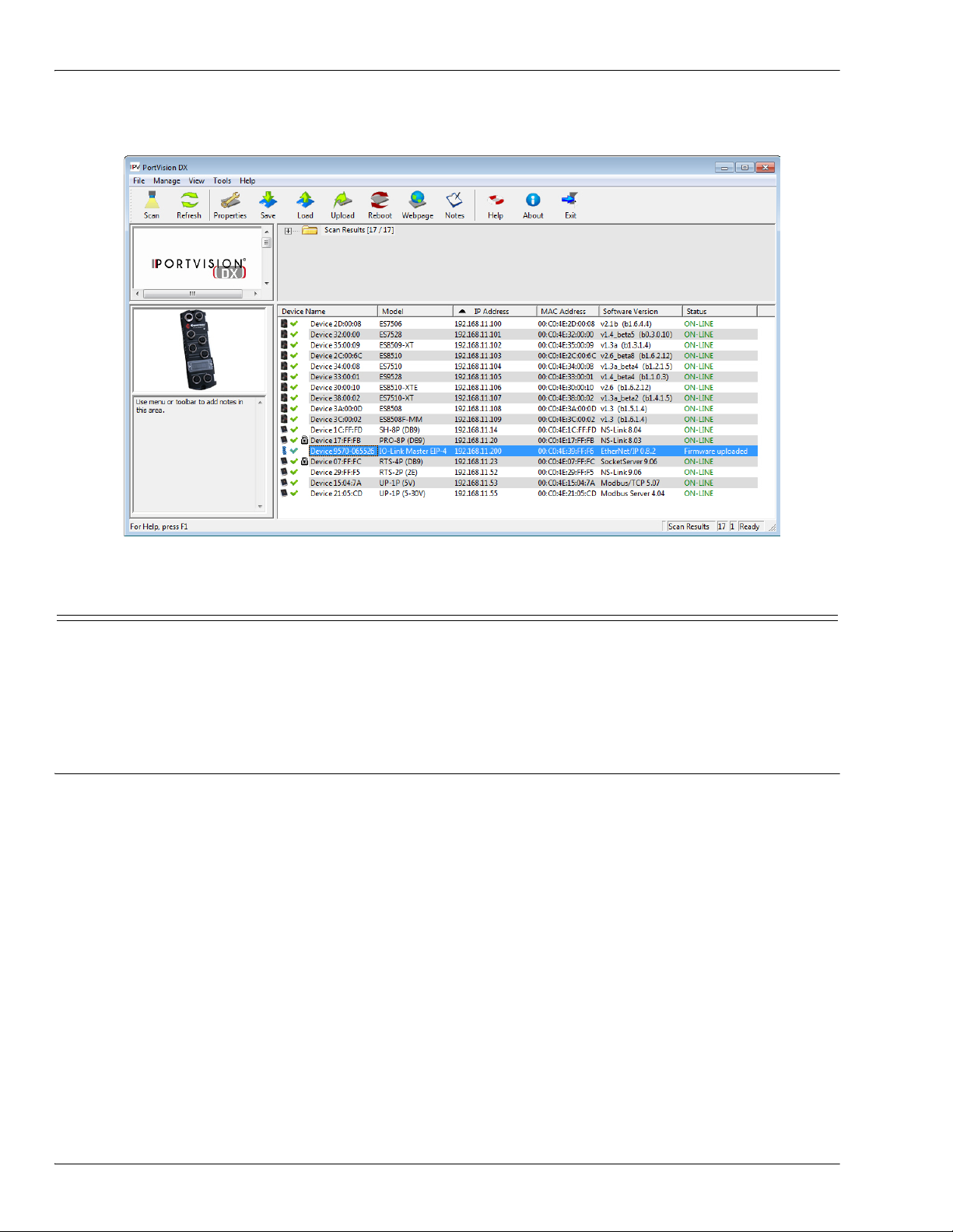
After PortVision DX is installed and the network has been scanned for Comtrol devices, the devices are
IO-Link Master 4-EIP User Guide: 2000582 Rev. A Chapter 3. Initial Configuration - 13
Page 14

PortVision DX Overview
displayed in the Scan Results folder as shown in the following graphic.
You can use the PortVision DX help system to learn how to organize your devices.
14 - Chapter 3. Initial Configuration IO-Link Master 4-EIP User Guide: 2000582 Rev. A
Page 15

Installing PortVision DX
3.1.2. Installing PortVision DX
Use this procedure to install or update PortVision DX. You can install PortVision DX from the CD shipped
with the IO-Link Master or download the latest version. Refer to Locating the Latest Software and
Documentation on Page 8 to locate the latest version.
1. Execute the PortVision_DX_x.xx.msi file, where x.xx is the version number.
2. Click Next to start the installation.
3. Click I accept the terms in the License Agreement and Next.
4. Click Next to install in the default location or browse to another location and then click Next.
IO-Link Master 4-EIP User Guide: 2000582 Rev. A Chapter 3. Initial Configuration - 15
Page 16

Installing PortVision DX
5. Click Next to continue the installation.
6. Click Install.
7. Depending on your operating system, you may need to click Yes to the Do you want to allow the following
program to install software on this computer User Account Control popup message.
8. Click Finish.
9. Depending on your operating system, you may need to click Yes to the Do you want to allow the following
program to make changes on this computer User Account Control popup message.
PortVision DX is installed and you can use the next subsection to program the IP address into the IO-Link
Master.
16 - Chapter 3. Initial Configuration IO-Link Master 4-EIP User Guide: 2000582 Rev. A
Page 17

Programming the IP Address
3.1.3. Programming the IP Address
Use the following procedure to program the IP address into the IO-Link Master using PortVision DX.
Note: Optionally, you can use the web interface to configure or Rotary switch to configure the IP address. You
can also refer to 2.1.
The Rotary switch settings override the lower 3 digits (8 bits) of the static IP address configured in
PortVision DX or the Configuration/Network page.
1. Start PortVision DX by using the desktop icon or click PortVision DX in the Start menu.
2. Depending on the operating system you may need to click Yes to the Do you want to allow the following
program to make changes on this computer User Account Control popup message.
3. Click the Scan button to locate your IO-Link Master or IO-Link Masters on the network.
Setting the Rotary Switch on Page 7 or 3.2. Using the Web Interface on Page 19.
4. Click the hardware types that you want to locate and click Scan.
5. Right-click the IO-Link Master that you want to program in the Device List pane (lower) and click
Properties.
Optionally, you can double-click on the IO-Link Master to open the Properties tabs. It may take a few
moments for the next screen to open.
IO-Link Master 4-EIP User Guide: 2000582 Rev. A Chapter 3. Initial Configuration - 17
Page 18

Programming the IP Address
6. Optionally, enter a device name, which displays inPortVision DX on the Main screen.
Note: The MAC address, Serial Number, and Device Status fields are automatically completed and are
status-only fields.
7. Enter the appropriate network information on the General tab.
You can configure the IO-Link Master for a static IP address or set it to DHCP.
•If you select Static for the IP Type, you must enter a valid IPv4 address. If necessary, see your Network
Administrator for a valid IP address for this IO-Link Master.
The default IP address is: 192.168.1.250.
- Enter a valid subnet mask for your network. The default Subnet Mask is: 255.255.255.0.
- Enter a valid IP gateway address for your network. The default Gateway Address is: 0.0.0.0.
• If you select DHCP, this field displays the last IP address programmed into the IO-Link Master.
Note: Rotary switch settings override the lower 3 digits (8 bits) of static IP address.
8. Click Close to exit the Properties tabs.
18 - Chapter 3. Initial Configuration IO-Link Master 4-EIP User Guide: 2000582 Rev. A
Page 19

Using the Web Interface
9. You wait until PortVision DX polls to display the updated IO-Link Master IP address or you can click
Refresh until the new IP address is displayed in the Device List pane.
10. If you want to configure any of the following options, go to 3.2.
- Host name
- DNS servers
- Syslog Server IP/Host name
- Syslog Port
- SSH Server Enable
You are ready to configure the ports, refer to Chapter 5.
IO-Link Port Configuration on Page 31.
Using the Web Interface on Page 19:
3.2. Using the Web Interface
This subsection discusses using the web interface to configure the IP address.
Note: The rotary switch settings override the lower 3 digits (8 bits) of static IP address configured on the
You can use the following procedure to configure the IO-Link Master network settings if you have
administrative rights.
1. Open the IO-Link Master web interface using one of these method:
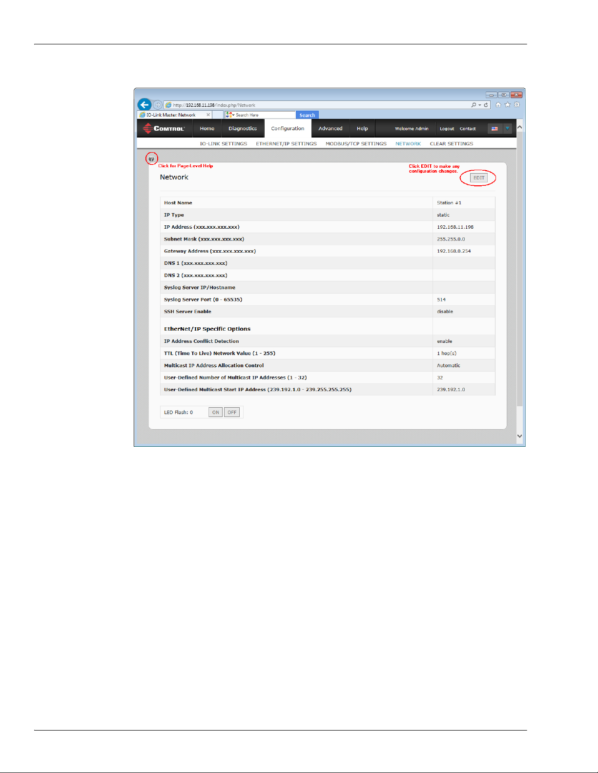
2. Click Configuration and then NETWORK.
Configuration/Network page. The default rotary switch setting uses the settings configured in the flash.
Optionally, you can use the web interface to configure the upper 9 digits (24 bits) and the rotary switch
to configure the lower 3 digits (8 bits) of the static IP address. You can also refer to 2.1. Setting the
Rotary Switch on Page 7 for additional information.
• From PortVision DX, highlight the IO-Link Master and click the Webpage button or right-click the IO-
Link Master in the Device List pane (lower pane) and click Webpage.
• Open your browser and enter the IP address of the IO-Link Master.
Note: The default IP address is 192.168.1.250.
IO-Link Master 4-EIP User Guide: 2000582 Rev. A Chapter 3. Initial Configuration - 19
Page 20
Using the Web Interface
3. Click the EDIT button.
4. Optionally, enter a host name to identify this IO-Link Master.
5. Select the IP type, Static or DHCP.
• If using a static IP address, enter the static IP address, subnet mask and IP gateway address.
•If using DNS:
- Enter the DNS primary server IP address.
- Optionally, enter the DNS secondary server IP address.
6. If you want the IO-Link Master to send syslog messages to a syslog server:
a. Enter the syslog server's IP address (or host name if using DNS).
b. Enter the syslog server's port number (default is 514).
7. If you want to enable the SSH server, click Enable.
8. Optionally, configure EtherNet/IP Specific Settings. You can refer to the help system for information about
these settings.
20 - Chapter 3. Initial Configuration IO-Link Master 4-EIP User Guide: 2000582 Rev. A
Page 21
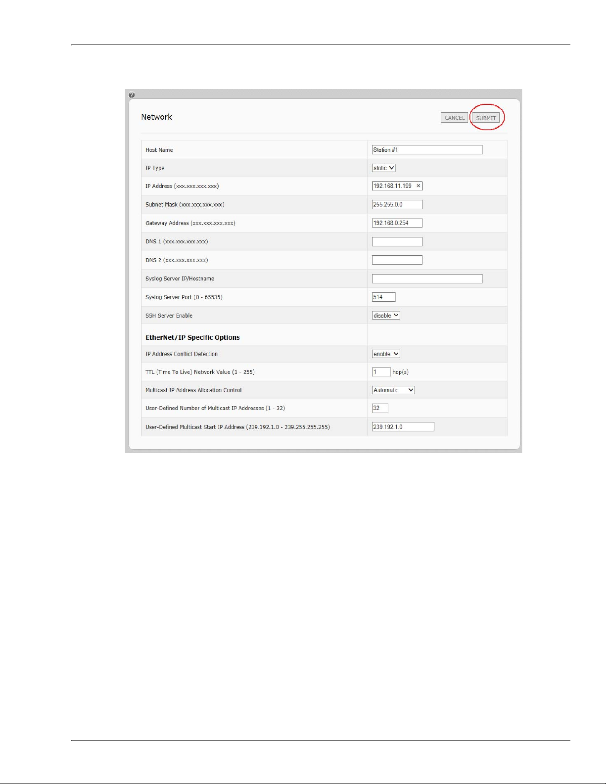
9. Click Submit to save the changes.
Using the Web Interface
10. If you want to return to the web page, you must enter the new IP address.
IO-Link Master 4-EIP User Guide: 2000582 Rev. A Chapter 3. Initial Configuration - 21
Page 22

Setting up Passwords
3.3. Setting up Passwords
The IO-Link Master is shipped from the factory without passwords. See the following table if you want to see
how permissions are granted.
Page Admin Operator User
Lo g- in Yes Yes Yes
Ho me Ye s Yes Ye s
Diagnostics - All Yes Yes Yes
Configuration - Port Settings Yes Yes No
Configuration - Network Yes No No
Advanced - Software Yes No No
Advanced - Accounts Yes No No
Advanced - Log Files Yes Yes Yes
Licences Yes Yes Yes
Help - All Yes Yes Yes
You can use this procedure to set up passwords for the IO-Link Master.
1. Open the IO-Link Master web interface using one of these method:
• From PortVision DX, highlight the IO-Link Master and click the Webpage button or right-click the IOLink Master in the Device List pane and click Webpage.
• Open your browser and enter the IP address of the IO-Link Master.
2. Click Advanced and then ACCOUNTS.
3. Click the ADMIN check box.
4. If applicable, enter the old password in the Old Password text box.
5. Enter the new password in the New Password text box.
6. Re-enter the password in the Confirm Password text box.
7. Optionally, click the Operator check box, enter a new password, and re-enter the password in the Confirm
Password text box.
22 - Chapter 3. Initial Configuration IO-Link Master 4-EIP User Guide: 2000582 Rev. A
Page 23

Setting up Passwords
8. Optionally, click the User check box, enter the new password, and re-enter the password in the Confirm
Password text box.
9. Click Apply.
10. Close the new window that displays a Password saved banner.
11. Click the Log out button (top navigation bar).
12. Re-open the web interface by selecting the appropriate audience in the drop list and entering the
password.
IO-Link Master 4-EIP User Guide: 2000582 Rev. A Chapter 3. Initial Configuration - 23
Page 24

Setting up Passwords
24 - Chapter 3. Initial Configuration IO-Link Master 4-EIP User Guide: 2000582 Rev. A
Page 25

Chapter 4. Updating Images and Application Subassemblies
This section discusses the following topics:
• 4.1. Images and Application Subassemblies Overview
• 4.2. Using PortVision DX to Update Software on Page 27
• 4.3. Using the Web Interface to Update Software on Page 28
4.1. Images and Application Subassemblies Overview
This subsection discusses images and application subassemblies. The IO-Link Master is loaded with the
latest images at the factory but you may need to update images or application subassemblies to have access to
the latest features.
You can view all image and application versions in the IO-Link Master ADVANCED/Software web page.
PortVision DX displays the main application base version, which in this case is EtherNet/IP.
IO-Link Master 4-EIP User Guide: 2000582 Rev. A Chapter 4. Updating Images and Application Subassemblies - 25
Page 26

Images
4.1.1. Images
The following table discusses IO-Link Master images.
IO-Link Master Images
U-Boot is a high-level bootloader that has networking and console command line
capabilities. Among other things, it implements a TFTP server and Comtrol
U-Boot Bootloader
FPGA
uImage - Primary/
Backup
Application Base
Corporation's new discovery protocol.
This verifies that a Linux kernel image exists in NAND, then copies it to RAM and
starts the IO-Link Master. The U-Boot version is displayed after the image name.
The FPGA partition/image contains configuration data used by programmable
hardware within the IO-Link Master unit.
The uImage contains the Linux kernel and the RAM-resident root file system. It does
not contain industrial protocol support or application-specific features.
There is a Primary and Backup version loaded on the IO-Link Master. The IO-Link
Master automatically reloads the Backup uImage if the file system corrupted.
The uImage version is displayed after the Primary/Backup uImage.
The Application Base image comprises a flash-resident file system containing
application and protocol support.
The Application Base is built from a collection of application subassemblies -- each of
which may be updated individually between releases of the application base as a
whole.
The application subassemblies in the Application Base image are displayed in the
lower portion of the SOFTWARE web page.
The Application Base assembly has a 2-tuple version number: (for example, 1.10).
4.1.2. Application Subassemblies
Application subassemblies are the components of the Application Base image. Application subassemblies
have 3-tuple or 4-tuple version numbers (for example, 1.10.1). The first two values in a subassembly version
correspond to the version of the application base assembly for which it was built and tested.
For example, a subassembly with version 1.10.3 was tested with application base version 1.10. When using
the SOFTWARE page or PortVision DX, an application subassembly can install only if its version number
matches that of the installed application base assembly. A subassembly with a version of 1.20.2.4 only installs
if the application base version is 1.20. It will not install on a device with application base version 1.09 or 1.20.
IO-Link Master Application Subassemblies
application-manager The Application Manager version loaded on the IO-Link Master.
configurationmanager
discovery-protocol The Discovery Protocol version loaded on the IO-Link Master.
ethernetip The EtherNet/IP interface loaded on the IO-Link Master.
event-log The Event log version loaded on the IO-Link Master.
iolink-driver The IO-Link version loaded on the IO-Link Master.
web-user-interface The web interface version loaded on the IO-Link Master.
ethernetip The EtherNet/IP version loaded on the IO-Link Master.
The Configuration Manager version loaded on the IO-Link
Master.
26 - Chapter 4. Updating Images and Application Subassemblies IO-Link Master 4-EIP User Guide: 2000582 Rev. A
Page 27

Using PortVision DX to Update Software
4.2. Using PortVision DX to Update Software
Use the following procedure to update software (images or application subassemblies) on the IO-Link Master.
1. If necessary, start PortVision DX.
2. Right-click the IO-Link Master that you want to update and click Advanced and then Upload Firmware.
3. Browse to the location you saved the software, highlight the file name, and click Open.
4. Click Yes to the Upload Firmware... Important Notice.
5. Click Ok to the Upload Firmware... Status message.
IO-Link Master 4-EIP User Guide: 2000582 Rev. A Chapter 4. Updating Images and Application Subassemblies - 27
Page 28
Using the Web Interface to Update Software
You may notice that PortVision DX first displays a Firmware uploaded status message. After the next
PortVision DX polling cycle the status message displays ON-LINE.
4.3. Using the Web Interface to Update Software
The upper portion of this page is used to update the IO-Link Master images. The lower portion of this page is
used for updating application subassemblies that are integrated in the Application Base. Typically, the latest
application subassemblies are available in the Application Base image. There may times when a feature
enhancement or bug fix is available in an application subassembly and not yet available in the Application
Base image.
4.3.1. Updating Images
Use this procedure to upload images using the SOFTWARE page.
1. Download the latest image from the Comtrol ftp site.
2. Open the IO-Link Master web interface using one of these methods:
• From PortVision DX, highlight the IO-Link Master and click the Webpage button or right-click the IO-
Link Master in the Device List pane and click Webpage.
• Open your browser and enter the IP address of the IO-Link Master.
3. Click ADVANCED and SOFTWARE.
4. Click the UPDATE button next to the image you want to update.
5. Click the Browse button (or Choose File, depending on the web browser), navigate to the file location,
highlight the image file, and click Open.
28 - Chapter 4. Updating Images and Application Subassemblies IO-Link Master 4-EIP User Guide: 2000582 Rev. A
Page 29

6. Click the Install button.
Updating Application Subassemblies
7. Click the CONTINUE button to the Update Image message.
8. Click Ok to close the Update Image Successful message.
4.3.2. Updating Application Subassemblies
Use this procedure to upload applications using the Software page.
1. Download the latest application from the Comtrol Corporation ftp site.
2. Open the IO-Link Master web interface using one of these method:
• From PortVision DX, highlight the IO-Link Master and click the Webpage button or right-click the IOLink Master in the Device List pane and click Webpage.
• Open your browser and enter the IP address of the IO-Link Master.
3. Click ADVANCED and SOFTWARE.
4. Click the Browse button (Choose File, depending on the web browser) under Update Application navigate to
the file location, highlight the image file, and click Open.
IO-Link Master 4-EIP User Guide: 2000582 Rev. A Chapter 4. Updating Images and Application Subassemblies - 29
Page 30

Updating Application Subassemblies
5. Click the Install button.
6. Click the CONTINUE button to the Update Application message.
7. Click Ok to close the Update Application Successful message.
30 - Chapter 4. Updating Images and Application Subassemblies IO-Link Master 4-EIP User Guide: 2000582 Rev. A
Page 31

Chapter 5. IO-Link Port Configuration
This section discusses port configuration, which includes these topics:
• 5.1. IO-Link Settings Configuration Page
• 5.2. EtherNet/IP Settings Configuration Page on Page 33
• 5.3. Modbus/TCP Settings Configuration Page on Page 40
Depending on your needs, the IO-Link Master you may not to change many of the default options.
You may want to refer to the following Reference Manuals for additional information. The IO-Link Master
Reference Manuals also contain information about using the sample programs.
• IO-Link Master EtherNet/IP Reference Manual
• IO-Link Master Modbus/TCP Reference Manual
Note: The IO-Link Master may work out of the box for ControlLogix PLCs.
5.1. IO-Link Settings Configuration Page
Use the IO-Link Settings page to configure IO-Link port characteristics for the IO-Link Master.
IO-Link Master 4-EIP User Guide: 2000582 Rev. A Chapter 5. IO-Link Port Configuration - 31
Page 32

Editing IO-Link Settings
5.1.1. Editing IO-Link Settings
You can use this procedure to configure IO-Link characteristics for each port. The following table or help
system provides information about each option.
1. If necessary, open the IO-Link Master web interface with your web browser using the IP address or
through PortVision DX.
2. Click Configuration in the menu bar, which by default loads the IO-Link Settings page.
3. Click the EDIT button for the port that you want to configure.
4. Make appropriate selections for the IO-Link device that you will connect to that port. You can use the help
system if you require definitions or values for the options or 5.1.2.
IO-Link Settings Parameters on Page
32.
5. Click the SAVE button.
6. Repeat for each port that requires configuration changes.
5.1.2. IO-Link Settings Parameters
The IO-Link Settings configuration page supports the following options.
IO-LINK SETTINGS Page
User defined port or device description.
Port Name
Port Mode
Default: IO-Link
Invert IO
Default: False
Minimum Cycle Time
Default: 4
• Standard ASCII characters
• Max length = 80 characters
Selected IO-Link Port Mode. Valid settings are:
• Reset
•IO-Link
• Digital In
• Digital Out
If enabled and the Port Mode is Digital In or Digital
Out, inverts the I/O value.
0= False (Disabled - Do not invert IO)
1= True (Enabled - Invert IO)
Note: Does not affect the Auxiliary Input.
The minimum, or fastest, cycle time that the IO-Link
device may operate at. The valid range is 4-65535 ms.
32 - Chapter 5. IO-Link Port Configuration IO-Link Master 4-EIP User Guide: 2000582 Rev. A
Page 33
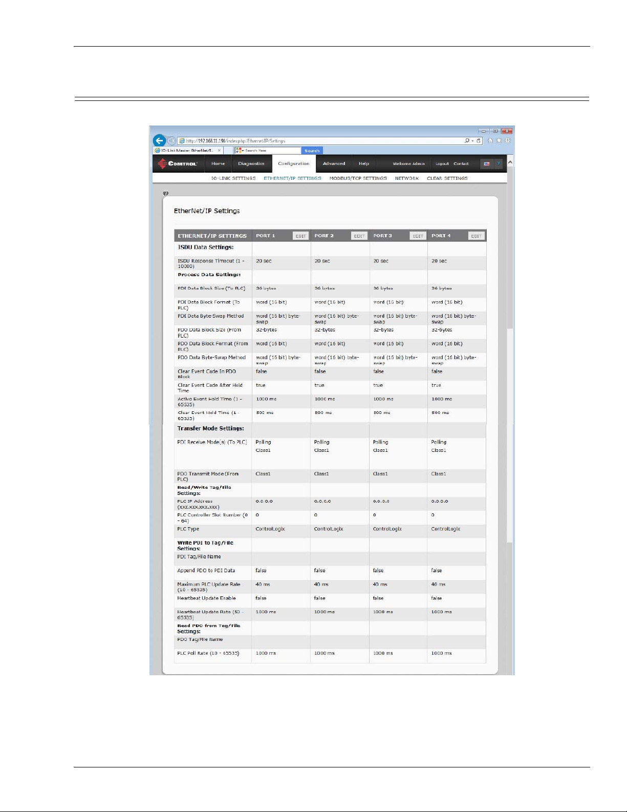
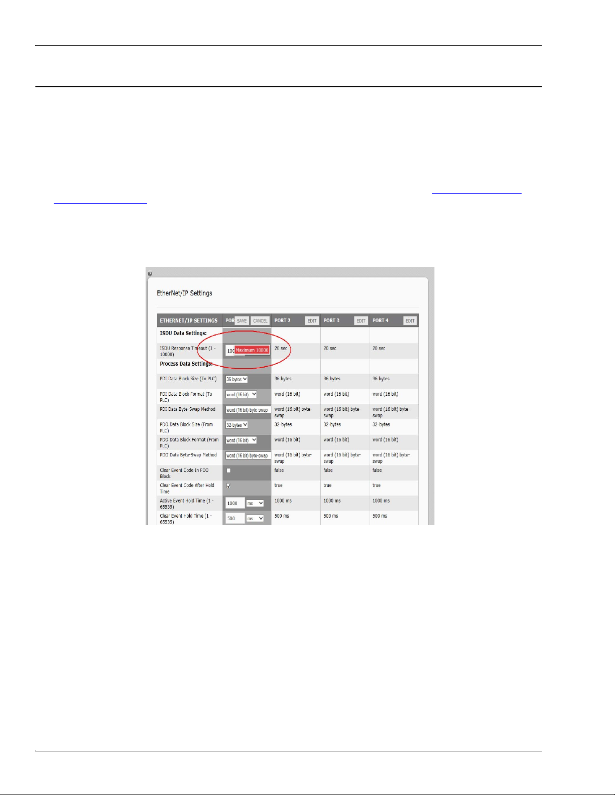
5.2. EtherNet/IP Settings Configuration Page
Use the EtherNet/IP Settings page to configure EtherNet/IP port options.
EtherNet/IP Settings Configuration Page
IO-Link Master 4-EIP User Guide: 2000582 Rev. A Chapter 5. IO-Link Port Configuration - 33
Page 34
Editing EtherNet/IP Settings
5.2.1. Editing EtherNet/IP Settings
You can use this procedure to configure EtherNet/IP characteristics for each port.
1. If necessary, open the IO-Link Master web interface with your web browser using the IP address.
2. Click Configuration in the menu bar.
3. Click the ETHERNET/IP SETTINGS submenu.
4. Click the EDIT button for the port that you want to configure.
5. Make appropriate selections for the IO-Link device that you will connect to that port.
You can use the help system if you require definitions or values for the options or 5.2.2. EtherNet/IP
Settings Parameters on Page 35.
6. Scroll to the top of the page and click the SAVE button.
Make sure that the port now displays the EDIT button.
If it displays the SAVE and CANCEL buttons, that means that one of the parameters contains an incorrect
value. If necessary, scroll down the page, make the needed corrections, and click SAVE.
7. Repeat for each port that requires configuration changes.
34 - Chapter 5. IO-Link Port Configuration IO-Link Master 4-EIP User Guide: 2000582 Rev. A
Page 35

5.2.2. EtherNet/IP Settings Parameters
The EtherNET/IP Settings configuration page supports the following options.
EtherNet/IP Settings Page
ISDU Data Settings
The time that the IO-Link Master’s EtherNet/IP interface waits for a
ISDU Response Timeout
Default: 20 seconds
Process Data Settings
PDI Data Block Size (To PLC)
Default: 36-bytes
PDI Data Block Format (To
PLC)
Default: Word-16
PDI Data Byte-Swap Method
Default: Work (16-bit) byte swap
response to an ISDU request.
The timeout needs to set long enough to allow all commands within the
ISDU request to be processed.
Valid range: 1-10,000 seconds
The configurable PDI data block length. Supported optional lengths are:
• 4-bytes (header only)
• 8-bytes (4 bytes data)
• 16-bytes (12 bytes data)
• 24-bytes (20 bytes data)
• 36-bytes (32 bytes data)
Data format of PDI data block to be transferred to the PLC(s) in Class 1
and/or Write-to-Tag/File PDI Transfer Modes. Supported formats are:
• Byte-8 (8-bit or SINT)
• Word-16 (16-bit or INT)
• Dword-32 (32-bit or DINT)
Note: The Data Block Format is independent of the PDI Data Byte-Swap
Method.
This setting is not used for the SLC, PLC-5 and MicroLogix PLCs
which are always Word-16.
If enabled, the IO-Link Master swaps the data bytes in word (2 byte)
format or dword (4 byte) format.
Supported values are:
• No byte-swap – data passed through as received
• Word (16-bit) byte-swap – data is byte-swapped in word format
• Dword (32-bit) byte-swap – data is byte-swapped in dword format
Note: The byte swapping must be set correctly in order to convert from IO-
Link (big-endian byte order), to EtherNet/IP (little-endian byte
order).
EtherNet/IP Settings Parameters
IO-Link Master 4-EIP User Guide: 2000582 Rev. A Chapter 5. IO-Link Port Configuration - 35
Page 36

EtherNet/IP Settings Parameters
PDO Data Block Size (From
PLC)
Default: 32-bytes
PDO Data Block Format (From
PLC)
Default: Word-16
EtherNet/IP Settings Page (Continued)
The configurable PDO data block length. Supported optional lengths are:
• Event code not included:
- 4-bytes = all data
- 8-bytes = all data
- 16-bytes = all data
- 24-bytes = all data
- 32-bytes = all data
- 34-bytes = 32 bytes data, 2 pad bytes
- 36-bytes = 32 bytes data, 4 pad bytes
• Event code included - PDO Data Format = Byte8:
- 4-bytes = 2 byte event code, 2 data bytes
- 8-bytes = 2 byte event code, 6 data bytes
- 16-bytes = 2 byte event code, 14 data bytes
- 24-bytes = 2 byte event code, 22 data bytes
- 32-bytes = 2 byte event code, 30 data bytes
- 34-bytes = 2 byte event code, 32 data bytes
- 36-bytes = 2 byte event code, 32 data bytes, 2 byte pad
• Event code included - PDO Data Format = word (16-bit):
- 4-bytes = event code word, data word
- 8-bytes = event code word, 3 data words
- 16-bytes = event code word, 7 data words
- 24-bytes = event code word, 11 data words
- 32-bytes = event code word, 15 data words
- 34-bytes = event code word, 16 data words
- 36-bytes = event code word, 16 data words, pad word
• Event code included - PDO Data Format = dword (32-bit):
- 4-bytes = event code dword
- 8-bytes = event code dword, data dword
- 16-bytes = event code dword, 3 data dwords
- 24-bytes = dword event code, 5 data dwords
- 32-bytes = dword event code, 7 data dwords
- 34-bytes = dword event code, 7 data dwords, 2 data bytes
- 36-bytes = dword event code, 8 data dwords
Data format of PDO data block received from the PLC(s) in Class 1 or
Read from TagOrFile PDO Transfer Modes. Formats include:
• Byte-8 (8-bit)
• Word-16 (16-bit)
• Dword-32 (32-bit)
Note: The Data Block Format is independent of the PDO Data Byte-Swap
Method.
This setting is not used for the SLC, PLC-5 and MicroLogix PLCs
which are always Word-16.
36 - Chapter 5. IO-Link Port Configuration IO-Link Master 4-EIP User Guide: 2000582 Rev. A
Page 37

PDO Data Byte-Swap Method
Default: Word (16-bit) byte-swap
Clear Event Code in PDO Block
Default: False
Clear Event Code After Hold
Time
Default: True
Event Active Hold Time
Default: 1000 ms
Clear Event Hold Time
Default: 500 ms
EtherNet/IP Settings Parameters
EtherNet/IP Settings Page (Continued)
If enabled, the IO-Link Master swaps the data bytes in word (2 byte)
format or dword (4 byte) format. Supported values are:
• No byte-swap – data passed through as received
• Word (16-bit) byte-swap – data is byte-swapped in word format
• Dword (32-bit) byte-swap – data is byte-swapped in dword format
Note: The byte swapping must be set correctly in order to convert from
EtherNet/IP (little-endian byte order), to IO-Link (big-endian byte
order).
If enabled, the IO-Link Master expects the first 2 bytes, word, or dword of
the PDO block to be used for event code handling. Supported values are:
• True = expect event code
• False = no event code, expect only PDO data
If enabled, the IO-Link Master clears any event code reported in the PDI
data block after the Event Active Hold Time. Supported values are:
• True = clear event code after hold time
• False = do not clear event code after hold time
If Clear Event Code After Hold time is enabled, the time period an event
code is reported in the PDI block before it is cleared.
• Valid range: 1-65535
• Valid Units:
- ms (milliseconds)
- sec (seconds)
- min (minutes)
-hours
-days
Once an event code has been cleared, the time an event code stays cleared
in the PDI block before another event code can be reported.
• Valid range: 1-65535
• Valid Units:
- ms (milliseconds)
- sec (seconds)
- min (minutes)
-hours
-days
IO-Link Master 4-EIP User Guide: 2000582 Rev. A Chapter 5. IO-Link Port Configuration - 37
Page 38

EtherNet/IP Settings Parameters
Transfer Mode Settings
PDI Receive Mode(s)
Default: Polling, Class1
PDO Transmit Mode
Default: Class 1
Read/Write Tag/File Settings
PLC IP Address
Default: 0.0.0.0
PLC Controller Slot Number
Default: 0
PLC Type
Default: ControlLogix
Write PDI to Tag/File Settings
PDI Tag/File Name
Default: blank
Append PDO to PDI Data
Default: False
EtherNet/IP Settings Page (Continued)
Determines which PDI Receive (To PLC) Modes are enabled. Supported
modes are:
•Polling
• Class1
• Write-to-TagOrFile
Supported modes are:
•Off
• PLC-Writes
• Class1
• Read-from-TagOrFile
The PLC IP Address is required if either Write-to-TagOrFile or Read-from-
TagOrFile mode are enabled.
Format: xxx.xxx.xxx.xxx
The PLC Controller Slot Number is required if either Write-to-TagOrFile
or Read-from-TagOrFile mode are enabled.
Valid range: 0-64
Indicates the type of PLC that the tag(s) or file(s) are written to and/or
read from. Supported PLC Types are:
• ControlLogix
•SLC
• PLC-5
• MicroLogix
The tag or file name to place the PDI data block.
• ControlLogix family:
- Tags must be same type as PDI Data Format (SINT, INT or DINT).
- Tags must be an array.
- Tags must be at least as long as the PDI Data Block Length.
• SLC/PLC-5/MicroLogix:
- Files must be of INTEGER (16-bit) type.
- Files must be named with standard file name conventions (i.e:
N10:0, N21:30, etc)
- The file must be at least as long as the PDI Data Block Length.
If selected, the IO-Link Master appends any PDO data to the end of the
PDI data.
• False = Do not append PDO data
• True = Append PDO data
38 - Chapter 5. IO-Link Port Configuration IO-Link Master 4-EIP User Guide: 2000582 Rev. A
Page 39

EtherNet/IP Settings Page (Continued)
Maximum PLC Update Rate
Default: 40ms
Heartbeat Update Enable
Default: False
Heartbeat Update Rate
Default: 1000ms
Read PDO from Tag/File Settings
PDO Tag/File Name
Default: blank
PLC Poll Rate
Default: 1000ms
EtherNet/IP Settings Parameters
The maximum rate at which the IO-Link Master updates the PDI tag or
file.
This parameter is used to ensure that the PLC receives all state changes.
Setting the update rate to 10 ms effectively disables this feature. The
valid range is 10 to 65535 ms.
If selected, the IO-Link Master updates the PDI data block at the
Heartbeat Update Rate.
• False = Heartbeat update disabled
• True = Heartbeat update enabled
If Heartbeat Update Enable is selected, the rate at which the IO-Link
Master updates the PDI data block in the Write-to-Tag/File mode.
The valid range is 50 to 65535 ms.
The tag or file name that the IO-Link Master reads the PDO data block
from.
• ControlLogix family:
- Tags must be same type as PDO Data Format (SINT, INT or
DINT).
- Tags must be an array.
- Tags must be at least as long as the PDO Data Block Length.
• SLC/PLC-5/MicroLogix:
- Files must be of INTEGER (16-bit) type.
- Files must be named with standard file name conventions (i.e:
N10:0, N21:30, etc)
The file must be at least as long as the PDO Data Block Length.
The frequency which the IO-Link Master reads the PDO data block in the
Read-from-Tag/File mode.
Valid range: 50-65535 ms
IO-Link Master 4-EIP User Guide: 2000582 Rev. A Chapter 5. IO-Link Port Configuration - 39
Page 40
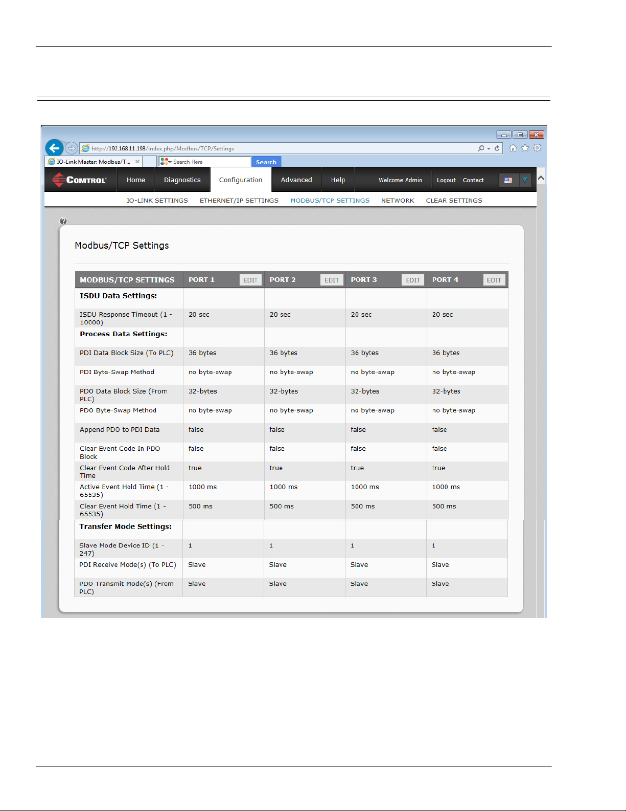
Modbus/TCP Settings Configuration Page
5.3. Modbus/TCP Settings Configuration Page
You can use the Modbus/TCP Settings page to configure Modbus/TCP with the IO-Link Master.
40 - Chapter 5. IO-Link Port Configuration IO-Link Master 4-EIP User Guide: 2000582 Rev. A
Page 41

Editing Modbus/TCP Settings
5.3.1. Editing Modbus/TCP Settings
1. If necessary, open the IO-Link Master web interface with your web browser using the IP address.
2. Click Configuration in the menu bar.
3. Click the MOD BUS/TCP SETTINGS submenu.
4. Click the EDIT button for the port that you want to configure.
5. Make appropriate selections for the IO-Link device that you will connect to that port. You can use the help
system if you require definitions or values for the options or 5.3.2.
Page 41.
6. Scroll to the top of the page and click the SAVE button.
Make sure that the port now displays the EDIT button.
If it displays the SAVE and CANCEL buttons, that means that one of the parameters contains an incorrect
value. If necessary, scroll down the page, make the needed corrections, and click SAVE.
Modbus/TCP Settings Parameters on
5.3.2. Modbus/TCP Settings Parameters
The following table illustrates the Modbus/TCP Settings page.
Modbus/TCP Settings Page
The time that the IO-Link Master’s Modbus/TCP interface waits for
ISDU Response Timeout
Default = 20 seconds
Process Data Settings
PDI Data Block Size
Default: 36-bytes
PDI Byte-Swap Method
Default: No byte-swap
a response to an ISDU request. The timeout needs to set long
enough to allow all commands within the ISDU request to be
processed.
Valid range: 1-10,000 seconds
The configurable PDI data block length. Optional lengths are:
• 4-bytes (header only)
• 8-bytes (4 bytes data)
• 16-bytes (12 bytes data)
• 24-bytes (20 bytes data)
• 36-bytes (32 bytes data)
If enabled, the IO-Link Master swaps the data bytes in word (2 byte)
format or dword (4 byte) format. Options include:
• No byte-swap – data passed through as received
• Word (16-bit) byte-swap – data is byte-swapped in word format
• Dword (32-bit) byte-swap – data is byte-swapped in dword
format
Note: Because both IO-Link and Modbus/TCP use big-endian byte
ordering, byte swapping typically is not required for word and
dword data.
Byte swapping is most commonly required when receiving
byte (8-bit) data and it is desired to place the first data byte in
the least significant byte position of the holding register. For
these cases, word (16 bit) byte-swap is typically used.
IO-Link Master 4-EIP User Guide: 2000582 Rev. A Chapter 5. IO-Link Port Configuration - 41
Page 42

Modbus/TCP Settings Parameters
PDO Data Block Size
Default: 32-bytes
PDO Byte-Swap Method
Default: No byte-swap
Append PDO to PDI Data
Default: False
Clear Event Code in PDO Block
Default: False
Clear Event Code After Hold Time
Default: True
Modbus/TCP Settings Page (Continued)
The configurable PDO data block length. Optional lengths are:
Event code not included:
• 4-bytes = 2 data words
• 8-bytes = 4 data words
• 16-bytes = 8 data words
• 24-bytes = 12 data words
• 32-bytes = 16 data words
• 34-bytes = 16 data words, 1 pad word
Event code included:
• 4-bytes = event code word, 1 data word
• 8-bytes = event code word, 3 data words
• 16-bytes = event code word, 7 data words
• 24-bytes = event code word, 11 data words
• 32-bytes = event code word, 15 data words
• 34-bytes = event code word, 16 data words
If enabled, the IO-Link Master swaps the data bytes in word (2 byte)
format or dword (4 byte) format. Options include:
• No byte-swap – data passed through as received
• Word (16-bit) byte-swap – data is byte-swapped in word format
• Dword (32-bit) byte-swap – data is byte-swapped in dword
format
Note: Because both IO-Link and Modbus/TCP use big-endian byte
ordering, byte swapping typically is not required for word and
dword data.
Byte swapping is most commonly required when sending byte
(8-bit) data to the IO-Link device and it is desired to send the
least significant byte of the holding register first. For these
cases, word (16 bit) byte-swap is typically used.
If selected, the IO-Link Master appends any PDO data to the end of
the PDI data.
• False = Do not append PDO data
• True = Append PDO data
If enabled, the IO-Link Master expects the first word of the PDO
block to be used for event code handling.
Values are:
• True = expect event code
• False = no event code, expect only PDO data
If enabled, the IO-Link Master clears any event code reported in the
PDI data block after the Event Active Hold Time.
Values are:
• True = clear event code after hold time
• False = do not clear event code after hold time
42 - Chapter 5. IO-Link Port Configuration IO-Link Master 4-EIP User Guide: 2000582 Rev. A
Page 43

Event Active Hold Time
Default: 1000 ms
Clear Event Hold Time
Default: 500 ms
Transfer Mode Settings
Slave Mode Device ID
Default: 1
PDI Receive Mode(s)
Default: Slave
PDO Transmit Mode
Default: Slave
Modbus/TCP Settings Parameters
Modbus/TCP Settings Page (Continued)
If Clear Event Code After Hold Time is enabled, the time period an
event code is reported in the PDI block before it is cleared.
Valid range: 1-65535
Valid Units are:
• ms (milliseconds)
• sec (seconds)
• min (minutes)
•hours
•days
Once an event code has been cleared, the time an event code stays
cleared in the PDI block before another event code can be reported.
• Valid range: 1-65535
• Valid Units:
• ms (milliseconds)
• sec (seconds)
• min (minutes)
•hours
•days
The Modbus Device ID used to access this IO-Link port.
Range: 1-247
Determines which PDI Receive (To PLC) Modes are enabled.
The selectable modes is Slave.
Note: Not selecting slave mode disables Modbus/TCP access to the
PDI data block.
Selectable Modes are:
• Disabled
•Slave
IO-Link Master 4-EIP User Guide: 2000582 Rev. A Chapter 5. IO-Link Port Configuration - 43
Page 44

Modbus/TCP Settings Parameters
44 - Chapter 5. IO-Link Port Configuration IO-Link Master 4-EIP User Guide: 2000582 Rev. A
Page 45

Chapter 6. Connecting Devices
The IO-Link Master provides four IO-Link ports with M12 connectors (5-pin female/A
coded).
Note: Make sure that you tighten the cables properly to maintain IP67 capabilities.
This table provides signal information for the IO-Link connectors.
This table provides information that you may need regarding the IO-Link connectors.
Pin Signal Description
1 L+ Power supply (+)
2 DI Digital input
3 L- Power supply (-)
Communication signal, which supports
4 C/Q
5 N/A Not connected
Maximum IO-Link Supply 200mA
Maximum C/Q Current:
Peak C/Q Current:
C/Q & DI Input:
SDCI (IO-Link) or SIO (standard input/
output)
Current and Power Value
High
Low
High
Low
Maximum
Minimum
200mA
200mA
500mA
500mA
Power Input +0.5VDC
-0.5VDC
SDCI (IO-Link) Transmission Rates:
COM1
COM2
COM3
Note: IO-Link ports must have an approved cable or protective cover attached to the port guarantee IP67
compliance.
IO-Link Master 4-EIP User Guide: 2000582 Rev. A Chapter 6. Connecting Devices - 45
4.8Kbps
38.4Kbps
230.4Kbps
Page 46

Connecting Devices
46 - Chapter 6. Connecting Devices IO-Link Master 4-EIP User Guide: 2000582 Rev. A
Page 47

Chapter 7. Using the Diagnostics Pages
This section provides information about the following Diagnostics web pages.
• 7.1. IO-Link Port Diagnostics
• 7.2. EtherNet/IP Diagnostics on Page 50
• 7.3. Modbus/TCP Diagnostics on Page 54
7.1. IO-Link Port Diagnostics
The IO-Link Diagnostics page may be useful when trying to troubleshoot port issues related to IO-Link
configuration.
Note: This image does not illustrate the complete Diagnostics page.
IO-Link Master 4-EIP User Guide: 2000582 Rev. A Chapter 7. Using the Diagnostics Pages - 47
Page 48

IO-Link Port Diagnostics
The following table provides information about the IO-Link Diagnostics page.
IO-Link Diagnostics
Displays the active device mode:
• Reset = The port is configured to disable all functionality.
Port Mode
• IO-Link = The port is configured to IO-Link mode.
• Digital In = The port is configured to operate as a digital input.
• Digital Out = The port is configured to operate as a digital output.
Displays the port status:
• Inactive = The port is in active state. Typically, this indicates that the
device is either not attached or not detected.
• Initializing = The port is in the process of initializing.
Port Status
• Operational = The port is operational and, if in IO-Link mode,
communications to the IO-Link device has been established.
• PDI Valid = The PDI data is now valid.
• Fault = The port has detected a fault and is unable to re-establish
communications.
Device Vendor Name Displays the Device Vendor Name as stored in ISDU Index 16.
Device Product Name The Device Product Name as stored in ISDU Index 18.
Device Serial Number The Device Serial Number as stored in ISDU Index 21.
Device Hardware The Device Hardware Version as stored in ISDU Index 22.
Device Firmware The Device Firmware Version as stored in ISDU Index 23.
Device IO-Link Version The supported Device IO-Link Version as stored in ISDU Index 0.
Auxiliary Bit Status The current status of the auxiliary bit as received on Pin 2 of the IO-Link port.
Last Rx PDI Data (MS
Byte First)
The last Rx PDI data as received from the IO-Link device.
Device PDO Data Length The supported Device PDO Data Length, in bytes, as stored in ISDU Index 0.
Lost PDO Controller(s)
Errors
The number of times that the PDO controller(s) were present and then lost
connection.
PDO Data Valid Status of PDO data being received from controller(s).
Device PDI Data Length The supported Device PDI Data Length, in bytes, as stored in ISDU Index 0.
PDI Data Valid Current status of PDI data as received from the IO-Link device.
Last Tx PDO Data The last Tx PDO data.
Time Since Initialization The time since the last port initialization.
Lost Communication
Count
The number of times that communication has been lost to the IO-Link device.
Initialization Attempts The number of times the IO-Link port was initialized.
Initialization Errors The number of port initialization errors that occurred.
Process Data Errors The number of process data errors the port received.
Process Data Retries The number of process data retries the port performed.
Internal Communication
Errors
Device Communication
Errors
The number of IO-Link Master internal communication errors that occurred on
this port.
The number of device specific communication errors that occurred.
48 - Chapter 7. Using the Diagnostics Pages IO-Link Master 4-EIP User Guide: 2000582 Rev. A
Page 49

IO-Link Port Diagnostics
IO-Link Diagnostics (Continued)
ISDU Read Cmd Attempts The number of read ISDU command attempts.
ISDU Read Cmd Errors The number of read ISDU command errors.
Minimum ISDU Read
Cmd Resp Time
Maximum ISDU Read
Cmd Resp Time
Average ISDU Read Cmd
Resp Time
Average ISDU Read Cmd
Byte Time
ISDU Write Cmd
Attempts
The minimum, or shortest, read ISDU command response time.
The maximum, or longest, read ISDU command response time.
The average ISDU read command response time.
The average per-byte read ISDU command response time.
The number of write ISDU command attempts.
ISDU Write Cmd Errors The number of write ISDU command errors.
Minimum ISDU Write
Cmd Resp Time
Maximum ISDU Write
Cmd Resp Time
Average ISDU Write Cmd
Resp Time
Average ISDU Write Cmd
Byte Time
The minimum, or shortest, write ISDU command response time.
The maximum, or longest, write ISDU command response time.
The average ISDU write command response time.
The average per-byte ISDU write command response time.
Total Events The total number of events that were received on this port.
First Events Up to the first, or oldest, three events that were received on this port.
Last Events Up to the last, or most recent, three events that were received on this port.
IO-Link Master 4-EIP User Guide: 2000582 Rev. A Chapter 7. Using the Diagnostics Pages - 49
Page 50
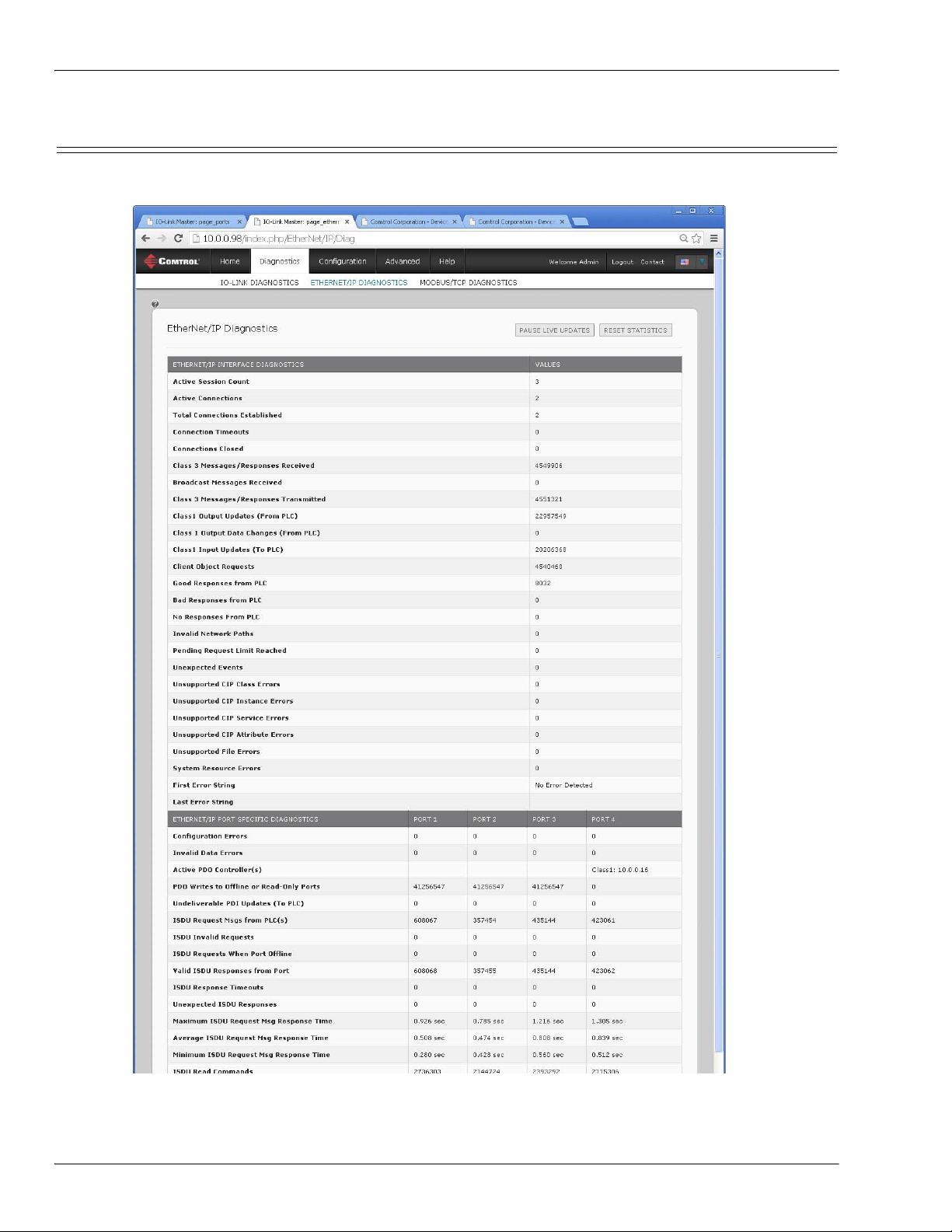
EtherNet/IP Diagnostics
7.2. EtherNet/IP Diagnostics
The EtherNet/IP Diagnostics page may be useful when trying to troubleshoot EtherNet/IP communications
and port issues related to EtherNet/IP configuration.
Note: This image does not illustrate the complete Diagnostics page.
50 - Chapter 7. Using the Diagnostics Pages IO-Link Master 4-EIP User Guide: 2000582 Rev. A
Page 51

EtherNet/IP Diagnostics
The following table provides information about the EtherNet/IP Diagnostics page.
EtherNet/IP Diagnostics
The number of active Ethernet/IP sessions. A session can:
Active Session Count
• Support both Class 1 I/O and Class 3 Messages
• Can be initiated by either the PLC or the IO-Link Master
• Can be terminated by either the PLC or the IO-Link Master
Active Connections The current number of active connections (both Class 1 and 3).
Total Connections
Established
The total number of connections that have been established.
Connection Timeouts The number of connections that have closed due to timing out.
Connections Closed The number connections that have closed due to a standard processes.
Class 3 Messages/
Responses Received
Broadcast Messages
Received
Class 3 Messages/
Responses Transmitted
Class 1 Output Updates
(From PLC)
Class 1 Output Data
Changes (From PLC)
Class 1 Input Data
Updates (To PLC)
The number of Class 3 messages and responses received from the PLC or
PLCs.
The number of broadcast messages received from PLC or PLCs.
The number of Class 3 messages and responses sent to the PLC or PLCs.
The number of Class 1 output data updates received from the PLC or PLCs.
The number of changes in Class 1 output data received from the PLC.
The number of Class 1 input data updates sent to the PLC or PLCs.
Client Object Requests The number of Class 3 requests to the IO-Link Master vendor specific objects.
Good Responses from PLC The number of good responses from messages sent to PLC or PLCs.
Displays the number of bad responses from messages sent to the PLC or
PLCs. Bad responses are typically returned for such errors as:
• Incorrect tag or file names
Bad Responses from PLC
• Incorrect tag or file data types
• Incorrect tag or file data sizes
• PLC is overloaded and cannot handle the amount of Ethernet traffic
• PLC malfunction
Displays the number of no responses from messages sent to the PLC or PLCs.
No responses are typically returned for such errors as:
• Incorrect IP address
No Responses from PLC
• Incorrect PLC configuration
• PLC malfunction
• PLC is overloaded and cannot handle the amount of Ethernet traffic
Invalid Network Paths
Pending Request Limit
Reached
Displays the number of network path errors on messages sent to the PLC or
PLCs. These are typically caused by incorrect IP address settings.
Displays the number of pending request limit errors. These errors occur when
the PLC is sending a continuous stream of messages to the IO-Link Master
faster than the IO-Link Master can process them.
Displays the number of unexpected event errors. Unexpected event errors
Unexpected Events
occur when the IO-Link Master receives an unexpected message from the
PLC such as an unexpected response or unknown message.
IO-Link Master 4-EIP User Guide: 2000582 Rev. A Chapter 7. Using the Diagnostics Pages - 51
Page 52

EtherNet/IP Diagnostics
EtherNet/IP Diagnostics (Continued)
Unsupported CIP Class
Errors
Unsupported CIP Instance
Errors
Unsupported CIP Service
Errors
Unsupported CIP Attribute
Errors
Unsupported File Errors
Displays the number of unsupported CIP class errors.
These errors occur when a message that attempts to access an invalid class is
received by the IO-Link Master.
Displays the number of unsupported CIP instance errors.
These errors occur when a message that attempts to access an invalid
instance is received by the IO-Link Master.
Displays the number of unsupported CIP service errors. These errors occur
when a message that attempts to access an invalid service is sent to the IOLink Master.
Displays the number of unsupported CIP request attribute errors. These
errors occur when a message that attempts to access an invalid attribute is
sent to the IO-Link Master.
Displays the number of messages from SLC/PLC-5/MicroLogix PLCs that
attempt to access an unsupported file address.
Displays the number of system resource errors. These errors indicate a
system error on the IO-Link Master such as operating system errors or full
System Resource Errors
message queues. These errors typically occur when the PLC or PLCs are
sending messages to the IO-Link Master faster than the IO-Link Master can
process them.
First Error String Text description of the first error that occurred.
Last Error String Text description of the last error that occurred.
EtherNet/IP Port Specific Diagnostics
Displays the number of improper configuration errors. These errors occur
Configuration Errors
when the IO-Link Master receives a message that cannot be performed due to
an invalid configuration.
Displays the number of invalid message data errors. These errors occur when
Invalid Data Errors
the IO-Link Master receives a message that cannot be performed due to
invalid data.
Active PDO Controller(s)
Lists the controller interface(s) type, (Class 1 or Class 3), and IP address that
are controlling the PDO data.
Displays the number of PDO write messages that were dropped due to any of
the following:
• The port is configured in IO-Link mode:
PDO Writes to Offline or
Read-Only Ports
- There is no device connected to the port.
- The IO-Link device is off-line.
- The IO-Link device does not support PDO data.
• The PDO Transmit Mode (To PLC) is disabled.
• The port is configured in Digital Input mode.
Displays the number of PDI update messages that could not be delivered to
the PLC in the Write-to-Tag/File method. Undeliverable updates may result
Undeliverable PDI
Updates (To PLC)
when:
The IO-Link Master cannot complete an Ethernet connection to the PLC.
The PDI data is changing faster than the Maximum PLC Update Rate.
ISDU Request Msgs From
PLC(s)
ISDU Invalid Requests
Displays the number of ISDU request messages received from the PLC(s) or
other controllers. These request messages may contain one or multiple ISDU
commands.
Displays the number of ISDU requests received over EtherNet/IP with one or
more invalid commands.
52 - Chapter 7. Using the Diagnostics Pages IO-Link Master 4-EIP User Guide: 2000582 Rev. A
Page 53

EtherNet/IP Diagnostics
EtherNet/IP Diagnostics (Continued)
Displays the number of ISDU requests received over EtherNet/IP when the
IO-Link port was offline. This can occur when:
ISDU Requests When Port
Offline
• The IO-Link port is initializing, such as after start-up.
• There is no IO-Link device attached to the port.
• The IO-Link device is not responding.
• Communication to the IO-Link device has been lost.
Valid ISDU Responses
From Port
ISDU Response Timeouts
Displays the number of valid ISDU response messages returned from the IOLink port interface and available to the PLC(s). The response messages
contain results to the ISDU command(s) received in the request message.
Displays the number of ISDU requests that did not receive a response within
the configured ISDU Response Timeout.
Displays the number of unexpected ISDU responses.
Unexpected ISDU
Responses
Unexpected responses may occur when an ISDU response is received after
the ISDU request has timed out. This typically requires setting the ISDU
Response Timeout to a longer value.
ISDU Read Commands Displays the number of ISDU read commands received over EtherNet/IP.
Maximum ISDU Request
Msg Response Time
Average ISDU Request
Msg Response Time
Minimum ISDU Request
Msg Response Time
Displays the maximum time period required to process all commands within
an ISDU request message. The response is not available until all ISDU
command(s) contained in the request have been processed.
Displays the average time period required to process the ISDU request
message(s). The response is not available until all ISDU command(s)
contained in the request have been processed.
Displays the minimum time period required to process all commands within
an ISDU request message. The response is not available until all ISDU
command(s) contained in the request have been processed.
ISDU Write Commands Displays the number of ISDU write commands received over EtherNet/IP.
ISDU NOP Commands
Displays the number of ISDU NOP (no operation) commands received over
EtherNet/IP.
IO-Link Master 4-EIP User Guide: 2000582 Rev. A Chapter 7. Using the Diagnostics Pages - 53
Page 54

Modbus/TCP Diagnostics
7.3. Modbus/TCP Diagnostics
The Modbus/TCP Diagnostics page may be useful when trying to troubleshoot Modbus/TCP communications
or port issues related to Modbus/TCP configuration.
The following table provides information about the Modbus/TCP Diagnostics page.
Modbus/TCP Diagnostics
Active Connections Displays the current number of active Modbus/TCP connections.
Messages Received from
Masters
Displays the number of Modbus messages received from Modbus/TCP
Masters.
Responses Sent to Masters Displays the number of Modbus responses sent to Modbus/TCP Masters.
Broadcasts Received Displays the number of broadcast Modbus/TCP messages received.
Invalid Message Length
Errors
Displays the number of Modbus messages received with incorrect length
fields.
Displays the number of invalid message data errors. These errors occur
Invalid Message Data Errors
when the IO-Link Master receives a message that cannot be performed due
to invalid data.
54 - Chapter 7. Using the Diagnostics Pages IO-Link Master 4-EIP User Guide: 2000582 Rev. A
Page 55

Modbus/TCP Diagnostics (Continued)
Modbus/TCP Diagnostics
Invalid Message Address
Errors
Displays the number of invalid message address errors. These errors occur
when the IO-Link Master receives a message that cannot be performed due
to an invalid address.
Displays the number of unknown device ID errors. These errors occur when
Unknown Device ID Errors
the IO-Link Master receives a message that is addressed to a device ID
other than the configured Slave Mode Device ID.
Displays the number of invalid message protocol type errors. These errors
Invalid Protocol Type Errors
occur when the IO-Link Master receives a Modbus/TCP message that
specifies a non-Modbus protocol..
Unsupported Function Code
Errors
Displays the number of invalid Modbus function code errors. These errors
occur when the IO-Link Master receives a message that cannot be
performed due to an unsupported Modbus function code.
Displays the number of improper configuration errors. These errors occur
Configuration Errors
when the IO-Link Master receives a message that cannot be performed due
to an invalid configuration.
No Available Connection
Errors
Displays the number of Modbus/TCP connection attempts that were
rejected due to no available connections. This occurs when the number of
Modbus/TCP connections has reached the limit.
Displays the number of system resource errors. These errors indicate a
system error on the IO-Link such as operating system errors or full
System Resource Errors
message queues. These errors typically occur when the PLC(s) are sending
messages to the IO-Link Master faster than the IO-Link Master can
process them.
First Error String Text description of the first error that occurred.
Last Error String Text description of the last error that occurred.
Modbus/TCP Port Specific Diagnostics
Active PDO Controller(s)
Lists the controller interface(s) type, (Class 1 or Class 3), and IP address
that are controlling the PDO data.
Displays the number of PDO write messages that were dropped due to any
of the following:
• The port is configured in IO-Link mode:
PDO Writes to Offline or
Read-Only Ports
- There is no device connected to the port.
- The IO-Link device is off-line.
- The IO-Link device does not support PDO data.
• The PDO Transmit Mode (To PLC) is disabled.
• The port is configured in Digital Input mode.
ISDU Request Msgs From
PLC(s)
ISDU Invalid Requests
Displays the number of ISDU request messages received from the PLC(s) or
other controllers. These request messages may contain one or multiple
ISDU commands.
Displays the number of ISDU requests received over Modbus/TCP with one
or more invalid commands.
Displays the number of ISDU requests received over Modbus/TCP when the
IO-Link port was offline. This can occur when:
ISDU Requests When Port
Offline
• The IO-Link port is initializing, such as after start-up.
• There is no IO-Link device attached to the port.
• The IO-Link device is not responding.
• Communication to the IO-Link device has been lost.
IO-Link Master 4-EIP User Guide: 2000582 Rev. A Chapter 7. Using the Diagnostics Pages - 55
Page 56

Modbus/TCP Diagnostics
Modbus/TCP Diagnostics (Continued)
Valid ISDU Responses From
Port
ISDU Response Timeouts
Displays the number of valid ISDU response messages returned from the
IO-Link port interface and available to the PLC(s). The response messages
contain results to the ISDU command(s) received in the request message.
Displays the number of ISDU requests that did not receive a response
within the configured ISDU Response Timeout.
Displays the number of unexpected ISDU responses. Unexpected responses
Unexpected ISDU Responses
may occur when an ISDU response is received after the ISDU request has
timed out. This typically requires setting the ISDU Response Timeout to a
longer value.
Maximum ISDU Request Msg
Response Time
Average ISDU Request Msg
Response Time
Minimum ISDU Request Msg
Response Time
Displays the maximum time period required to process all commands
within an ISDU request message. The response is not available until all
ISDU command(s) contained in the request have been processed.
Displays the average time period required to process the ISDU request
message(s). The response is not available until all ISDU command(s)
contained in the request have been processed.
Displays the minimum time period required to process all commands
within an ISDU request message. The response is not available until all
ISDU command(s) contained in the request have been processed.
ISDU Read Commands Displays the number of ISDU read commands received over Modbus/TCP.
ISDU Write Commands Displays the number of ISDU write commands received over Modbus/TCP.
ISDU NOP Commands
Displays the number of ISDU NOP (no operation) commands received over
Modbus/TCP.
56 - Chapter 7. Using the Diagnostics Pages IO-Link Master 4-EIP User Guide: 2000582 Rev. A
Page 57

Chapter 8. Troubleshooting and Technical Support
This section provides the following information:
• 8.1. Troubleshooting
• 8.2. Contacting Technical Support on Page 58
• 8.3. Using Log Files on Page 59
8.1. Troubleshooting
Before contacting Technical Support, you may want to try the following:
• Open the IO-Link Master web interface and review the following web pages:
- IO-Link Diagnostics
- EtherNet/IP Diagnostics
- Modbus/TCP Diagnostics
• Reboot the IO-Link Master
• Verify that you are using the correct types of cables on the correct connectors and that all cables are
connected securely.
• Check to make sure LEDs are not reporting an issue using 2.5. IO-Link Master LEDs (Page 12)
• Verify that the network IP address, subnet mask, and gateway are correct and appropriate for the
network. Make sure that the IP address programmed into the IO-Link Master matches the unique
reserved IP configured address assigned by the system administrator.
• If using DHCP, the host system needs to provide the subnet mask. The gateway is optional and is not
required for a purely local network.
• Remember that if the rotary switches are set to a non-default position, the rotary switches override the
lower 3 digits (8 bits) of the static IP address configured in the Network page or in PortVision DX.
• Verify that the Ethernet hub and any other network devices between the system and the IO-Link Master
are powered up and operating.
• If you have a spare IO-Link Master, try replacing the IO-Link Master.
IO-Link Master 4-EIP User Guide: 2000582 Rev. A Chapter 8. Troubleshooting and Technical Support - 57
Page 58

Contacting Technical Support
8.2. Contacting Technical Support
You may want to access the Help/SUPPORT page when you call Technical Support, as they may request the
information displayed on the SUPPORT page.
Comtrol Technical Support is available from 8:00AM to 6:00PM (CST), Monday through Friday, excluding
major USA holidays.
Contact Information
Phone 763.957.6000
Downloads ftp://ftp.comtrol.com/html/default.htm
Web Site http://www.comtrol.com
58 - Chapter 8. Troubleshooting and Technical Support IO-Link Master 4-EIP User Guide: 2000582 Rev. A
Page 59

Using Log Files
8.3. Using Log Files
Log files are available in the IO-Link Master web page. The IO-Link Master provides four different log files
that you can view, export, or clear:
• Syslog (system log) displays line-by-line activity records.
• dmesg displays Linux kernel messages.
• top displays which programs are using most of the memory and CPU.
• ps displays the running programs
• All log files start up automatically during the startup cycle. Each log file has a size limit of 100KB.
Note: Typically, log files are intended to be used by Technical Support in the event there is a problem.
You can use the following procedures to:
• 8.3.1. View a Log File on Page 59
• 8.3.2. Clear a Log File on Page 59
• 8.3.3. Export a Log File on Page 60
8.3.1. View a Log File
Use this procedure to view a log file.
1. Open the IO-Link Master web interface using one of these method:
• From PortVision DX, highlight the IO-Link Master and click the Webpage button or right-click the IO-
Link Master in the Device List pane and click Webpage.
• Open your browser and enter the IP address of the IO-Link Master.
2. Click Advanced and then LOG FILES.
3. Select the log file type from the drop-list.
4. Optionally, click the REFRESH button to get the latest information.
5. Optionally, export
the log file.
8.3.2. Clear a Log File
Use this procedure to clear a log file.
1. Open the IO-Link Master web interface using one of these method:
• From PortVision DX, highlight the IO-Link Master and click the Webpage button or right-click the IO-
IO-Link Master 4-EIP User Guide: 2000582 Rev. A Chapter 8. Troubleshooting and Technical Support - 59
Page 60

Export a Log File
Link Master in the Device List pane and click Webpage.
• Open your browser and enter the IP address of the IO-Link Master.
2. Click Advanced and then LOG FILES.
3. Optionally, export
the log file.
4. Select the log file type from the drop-list.
5. Click the CLEAR button.
The log file automatically starts logging the latest information.
8.3.3. Export a Log File
Use the following procedure to export a log file.
1. Open the IO-Link Master web interface using one of these method:
• From PortVision DX, highlight the IO-Link Master and click the Webpage button or right-click the IOLink Master in the Device List pane and click Webpage.
• Open your browser and enter the IP address of the IO-Link Master.
2. Click Advanced and then LOG FILES.
3. Select the log file type from the drop-list.
4. Click the EXPORT button.
5. Click the Save button drop-list and click Save to save it to your user folder or Save as to browse to or create
a new folder in which to place the log file.
6. Depending on your operating system, you may need to close the pop-up window.
60 - Chapter 8. Troubleshooting and Technical Support IO-Link Master 4-EIP User Guide: 2000582 Rev. A
Page 61

Export a Log File
IO-Link Master 4-EIP User Guide: 2000582 Rev. A Chapter 8. Troubleshooting and Technical Support - 61
Page 62

Export a Log File
62 - Chapter 8. Troubleshooting and Technical Support IO-Link Master 4-EIP User Guide: 2000582 Rev. A
 Loading...