

Page 1

Installation and Configuration Guide
Page 2

TrademarkNotices
DocumentNumber:2000594Rev.A
reviousPartNumber:2000506Rev.E
Comtrol,NS‐Link,andDeviceMasteraretrademarksofComtrolCorporation.
MicrosoftandWindowsareregisteredtrademarksofMicrosoftCorporation.
HyperTerminalisaregisteredtrademarkofHilgraeve,Inc.
PortionsofSocketServerarecopyrightedbyGoAheadSoftware,Inc.Copyright©2001.GoAheadSoftware,Inc.All
RightsReserved.
Otherproductnamesmentionedhereinmaybetrademarksand/orregisteredtrademarksoftheirrespectiveowners.
FirstEdition,May30,2014
Copyright©2001‐2014.ComtrolCorporation.
AllRightsReserved.
ComtrolCorporationmakesnorepresentationsorwarrantieswithregardtothecontentsofthisdocumentortothe
suitabilityoftheComtrolproductforanyparticularpurpose.Specificationssubjecttochangewithoutnotice.Some
softwareorfeaturesmaynotbeavailableatthetimeofpublication.Contactyourresellerforcurrentproduct
information.
Page 3

Table of Contents
Introduction ............................................................................................................................9
Supported DeviceMaster Models ............................................................................................................... 9
DeviceMaster Port Usage ............................................................................................................................ 9
Installation Overview ................................................................................................................................... 9
NS-Link COM Port Driver Installation Overview .................................................................................. 11
NS-Link tty Port Installation Overview.................................................................................................. 11
TCP/IP Socket Port Installation Overview.............................................................................................. 11
Locating Software and Documentation ................................................................................................. 12
Connectivity Requirements ...................................................................................................................... 13
Hardware Installation.........................................................................................................15
Installation Overview ................................................................................................................................. 15
1-Port - Enclosed Installation ................................................................................................................... 16
1-Port - Embedded Installation ................................................................................................................ 18
Building the Serial Ribbon Cable ............................................................................................................ 18
Mounting the Embedded .......................................................................................................................... 19
Attaching the Network and Serial Cables............................................................................................... 20
Connecting the Power and Verifying Installation .................................................................................. 20
2-Port (Serial Terminal) 1E/2E Installation .......................................................................................... 22
2-Port (DB9) 1E/2E Installation ................................................................................................................ 24
4-Port and 8-Port Installation................................................................................................................... 26
16-Port (DeviceMaster RTS - External Power Supply) Installation ................................................ 28
16-Port (DeviceMaster PRO) Installation .............................................................................................. 30
16/32-Port Rack Mount Models (Internal Power Supply) Installation............................................ 32
Initial Configuration ...........................................................................................................35
PortVision Plus ............................................................................................................................................ 35
PortVision DX Overview ............................................................................................................................ 35
PortVision DX Requirements.................................................................................................................... 36
Configuring Security Settings and PortVision DX .............................................................................. 36
Installing PortVision DX............................................................................................................................ 37
Configuring the Network Settings .......................................................................................................... 40
Checking the SocketServer Version ....................................................................................................... 43
Uploading SocketServer with PortVision DX .......................................................................................45
Customizing PortVision DX ...................................................................................................................... 47
Accessing DeviceMaster Documentation from PortVision DX ......................................................... 48
How to Download Documentation ........................................................................................................... 48
How to Open Previously Downloaded Documents .................................................................................. 49
DeviceMaster Installation and Configuration Guide: 2000594 Rev. A Table of Contents - iii
Page 4

Table of Contents
Device Driver (NS-Link) Installation ..............................................................................51
Overview........................................................................................................................................................ 51
Before Installing the NS-Link Driver...................................................................................................... 51
Linux Installations ...................................................................................................................................... 52
Windows Installations ................................................................................................................................ 53
Supported Operating Systems ................................................................................................................. 53
Installation Overview for Windows ......................................................................................................... 53
NS-Link for Windows Installation........................................................................................................... 53
Configuring the NS-Link Driver for Windows......................................................................................58
Configuring COM Port Properties for Windows .................................................................................. 61
Enabling Secure Data Mode...................................................................................................................... 62
Socket Port Configuration .................................................................................................65
SocketServer Overview.............................................................................................................................. 65
Web Page Help System............................................................................................................................. 65
SocketServer Architecture ....................................................................................................................... 66
Accessing Socket Configuration .............................................................................................................. 67
Web Browser ............................................................................................................................................. 67
PortVision DX ........................................................................................................................................... 67
SocketServer Versions ............................................................................................................................... 68
DeviceMaster Security........................................................................................................69
Understanding Security Methods and Terminology........................................................................... 69
TCP and UDP Socket Ports Used by the DeviceMaster ..................................................................... 74
DeviceMaster Security Features.............................................................................................................. 75
Security Modes.......................................................................................................................................... 75
Secure Data Mode and Secure Config Mode Comparison ...................................................................... 76
Security Comparison ................................................................................................................................ 77
SSH Server................................................................................................................................................ 77
SSL Overview............................................................................................................................................ 78
SSL Authentication .................................................................................................................................. 78
Server Authentication........................................................................................................................ 78
Client Authentication ......................................................................................................................... 79
Certificates and Keys ......................................................................................................................... 79
SSL Performance ...................................................................................................................................... 80
SSL Cipher Suites..................................................................................................................................... 81
DeviceMaster Supported Cipher Suites .................................................................................................. 81
SSL Resources .................................................................................................................................... 82
Configure/Enable Security Features Overview ................................................................................... 83
Example 1.................................................................................................................................................. 85
Example 2.................................................................................................................................................. 85
Example 3.................................................................................................................................................. 86
Key and Certificate Management ............................................................................................................ 86
Using a Web Browser to Set Security Features....................................................................................88
Changing Security Configuration ............................................................................................................ 88
Changing Keys and Certificates .............................................................................................................. 89
iv - Table of Contents DeviceMaster Installation and Configuration Guide: 2000594 Rev. A
Page 5

Table of Contents
Connecting Serial Devices .................................................................................................91
DB9 Connectors ........................................................................................................................................... 91
DB9 Null-Modem Cables (RS-232) .......................................................................................................... 92
DB9 Null-Modem Cables (RS-422) .......................................................................................................... 92
DB9 Straight-Through Cables (RS-232/485) ........................................................................................... 92
DB9 Loopback Plugs................................................................................................................................. 93
Connecting DB9 Serial Devices ............................................................................................................... 93
RJ45 Connectors .......................................................................................................................................... 94
RJ45 Null-Modem Cables (RS-232) ......................................................................................................... 94
RJ45 Null-Modem Cables (RS-422) ......................................................................................................... 95
RJ45 Straight-Through Cables (RS-232/485).......................................................................................... 95
RJ45 Loopback Plugs................................................................................................................................ 95
RJ45 RS-485 Test Cable ........................................................................................................................... 96
Connecting RJ45 Devices ......................................................................................................................... 96
Serial Terminals (4) - 1E............................................................................................................................. 97
Serial Terminal (4) Connectors ................................................................................................................ 97
Serial Terminal (4) Null-Modem Cables (RS-232) ..................................................................................98
Serial Terminal (4) Null-Modem Cables (RS-422) ..................................................................................98
Serial Terminal (4) Straight-Through Cables (RS-232/485) .................................................................. 98
Serial Terminal (4) Loopback Signals ..................................................................................................... 99
Connecting Serial Devices........................................................................................................................ 99
Serial Terminals (8) - 2E............................................................................................................................. 99
Serial Terminal (8) Connectors ................................................................................................................ 99
Serial Terminal (8) Null-Modem Cables (RS-232) ................................................................................ 100
Serial Terminal (8) Null-Modem Cables (RS-422) ................................................................................ 101
Serial Terminal (8) Straight-Through Cables (RS-232/485) ................................................................ 101
Serial Terminal (8) Loopback Signals ................................................................................................... 101
Connecting Serial Devices...................................................................................................................... 102
Managing the DeviceMaster ............................................................................................103
Rebooting the DeviceMaster................................................................................................................... 103
Uploading SocketServer to Multiple DeviceMasters ........................................................................ 104
Configuring Multiple DeviceMasters Network Addresses .............................................................. 105
Adding a New Device in PortVision DX ............................................................................................... 105
Remote Using the IP Address ................................................................................................................ 105
Local Using the IP Address or MAC Address .......................................................................................106
Using SocketServer Configuration Files ............................................................................................. 107
Saving a SocketServer Configuration File ............................................................................................ 107
Loading a SocketServer Configuration File .......................................................................................... 108
Using Driver Configuration Files .......................................................................................................... 109
Saving Driver Configuration Files......................................................................................................... 109
Saving Device-Level Configuration ................................................................................................. 109
Saving Port-Level Configuration..................................................................................................... 110
Loading Driver Configuration Files....................................................................................................... 111
Loading Device Configuration ......................................................................................................... 111
Changing the Bootloader Timeout ........................................................................................................ 115
Managing Bootloader ............................................................................................................................... 116
Checking the NS-Link Version ............................................................................................................... 118
Restoring Factory Defaults (2-Port, Only)........................................................................................... 119
Loading Port Configuration ............................................................................................................. 113
Checking the Bootloader Version........................................................................................................... 116
Uploading Bootloader ............................................................................................................................. 116
DeviceMaster Installation and Configuration Guide: 2000594 Rev. A Table of Contents - v
Page 6

Table of Contents
Restoring Serial Port Settings................................................................................................................ 119
NS-Link COM Port ................................................................................................................................. 120
Socket Port .............................................................................................................................................. 120
Accessing SocketServer Commands in Telnet/SSH Sessions (PortVision DX) ...........................121
Telnet Session ......................................................................................................................................... 121
SSH Session ............................................................................................................................................ 123
Accessing RedBoot Commands in Telnet/SSH Sessions (PortVision DX) .................................... 125
RedBoot Procedures..........................................................................................................129
Accessing RedBoot Overview ................................................................................................................. 129
Establishing a Serial Connection .......................................................................................................... 130
Establishing a Telnet Connection.......................................................................................................... 131
Determining the Network Settings ....................................................................................................... 132
Configuring the Network Settings ........................................................................................................ 132
Changing the Bootloader Timeout ........................................................................................................ 133
Determining the Bootloader Version.................................................................................................... 133
Resetting the DeviceMaster .................................................................................................................... 134
Configuring Passwords ............................................................................................................................ 134
RedBoot Command Overview................................................................................................................. 135
Hardware Specifications ..................................................................................................137
Locating DeviceMaster Specifications ................................................................................................. 137
External Power Supply Specifications................................................................................................. 138
1-Port 5VDC Power Supply .................................................................................................................... 138
1-Port 5-30VDC Power Supply............................................................................................................... 138
2-Port (Serial Terminals) Power Supply ............................................................................................... 139
2-Port (DB9) Power Supply .................................................................................................................... 139
4-Port Power Supply ............................................................................................................................... 140
8-Port Power Supply ............................................................................................................................... 140
16-Port Power Supplies .......................................................................................................................... 140
DeviceMaster Product Pictures ............................................................................................................. 142
1-Port (DB9) 5VDC ................................................................................................................................. 142
1-Port (DB9) 5-30VDC ............................................................................................................................ 143
1-Port Embedded .................................................................................................................................... 144
2-Port (Single Ethernet Port) with Serial Terminals ........................................................................... 144
2-Port (Dual Ethernet Ports) with Serial Terminals ............................................................................ 145
2-Port (Single Ethernet Port) DB9 ........................................................................................................ 145
2-Port (Dual Ethernet Ports) DB9 ......................................................................................................... 146
4-Port (DB9) ............................................................................................................................................ 146
8-Port (DB9) ............................................................................................................................................ 146
16-Port (RJ45) External Power Supply ................................................................................................. 146
16-Port (RJ45) Internal Power Supply .................................................................................................. 147
DeviceMaster PRO 16-Port (RJ45) ........................................................................................................ 147
DeviceMaster Serial Hub 16-Port (DB9) ............................................................................................... 147
DeviceMaster RTS 32-Port (RJ45)......................................................................................................... 147
Notices.......................................................................................................................................................... 148
Radio Frequency Interference (RFI) (FCC 15.105) ............................................................................... 148
Labeling Requirements (FCC 15.19) ..................................................................................................... 148
Modifications (FCC 15.21) ...................................................................................................................... 148
Serial Cables (FCC 15.27) ...................................................................................................................... 148
Underwriters Laboratory ....................................................................................................................... 148
Important Safety Information................................................................................................................ 148
vi - Table of Contents DeviceMaster Installation and Configuration Guide: 2000594 Rev. A
Page 7

Table of Contents
Troubleshooting and Technical Support......................................................................149
Troubleshooting Checklist ..................................................................................................................... 149
General Troubleshooting......................................................................................................................... 150
Testing Ports Using Port Monitor (PMon2) ........................................................................................153
Overview ................................................................................................................................................. 153
Testing Comtrol COM Ports................................................................................................................... 153
Testing Ports Using Test Terminal ....................................................................................................... 156
Overview ................................................................................................................................................. 156
Opening Ports ......................................................................................................................................... 157
Sending and Receiving Test Data (RS-232/422/485: 4-Wire) ............................................................... 158
Loopback Test (RS-232).......................................................................................................................... 158
Sending and Receiving Data (RS-485: 2-Wire) .....................................................................................159
Socket Mode Serial Port Testing ........................................................................................................... 162
Daisy-Chaining DeviceMaster 2E/4/8/16-Port Units .......................................................................... 168
DeviceMaster LEDs ................................................................................................................................... 169
TX/RX LEDs............................................................................................................................................ 169
Network and Device LEDs ..................................................................................................................... 169
Removing DeviceMaster Security Features........................................................................................ 171
Serial Connection Method ...................................................................................................................... 171
Returning the DeviceMaster to Factory Defaults.............................................................................. 173
Clearing the Flash .................................................................................................................................. 174
Clearing EEPROM.................................................................................................................................. 174
Telnet Access .................................................................................................................................... 174
Serial Port Access............................................................................................................................. 175
Web Server Access............................................................................................................................ 175
Technical Support ..................................................................................................................................... 177
DeviceMaster Installation and Configuration Guide: 2000594 Rev. A Table of Contents - vii
Page 8

Table of Contents
viii - Table of Contents DeviceMaster Installation and Configuration Guide: 2000594 Rev. A
Page 9

Introduction
This section discusses the following topics:
• Supported DeviceMaster Models on Page 9
• DeviceMaster Port Usage (below)
• Installation Overview on Page 9
- NS-Link COM Port Driver Installation Overview on Page 11
- NS-Link tty Port Installation Overview on Page 11
- TCP/IP Socket Port Installation Overview on Page 11
• Locating Software and Documentation on Page 12
• Connectivity Requirements on Page 13
Supported DeviceMaster Models
This Installation and Configuration Guide supports the DeviceMaster platform,
which includes the following models:
• DeviceMaster PRO
• DeviceMaster RTS
• DeviceMaster Serial Hub
The Guide refers to DeviceMaster unless there is model-specific information. FTP
links in this Guide typically point to an RTS subdirectory, where the file resides
that supports all DeviceMaster models.
Note: The DeviceMaster LT provides different RJ45 pin outs and is not discussed
in this guide. Refer to the DeviceMaster LT User Guide for product-specific
information.
DeviceMaster Port Usage
DeviceMaster serial ports can be configured for many environments, which
include the following:
• COM port (or secure COM ports) when the NS-Link driver for Windows is
installed
• tty ports when the NS-Link driver for Linux is installed
• Socket ports when SocketServer or the NS-Link web page is configured
accordingly
Installation Overview
DeviceMaster installation and configuration follows these steps:
1. Hardware installation.
Power up the DeviceMaster. Technical Support suggests installing one
DeviceMaster at a time to avoid configuration problems using
DeviceMaster Installation and Configuration Guide: 2000594 Rev. A Introduction - 9
Hardware
Page 10

Installation Overview
Installation on Page 15.
2. Install PortVision DX.
Note: PortVision DX replaces PortVision Plus. PortVision Plus does not
support operating systems above Windows 7 and SocketServer versions
above 9.00.
Comtrol recommends connecting the DeviceMaster to a PC or laptop running
Windows and that you install PortVision DX for easy IP address configuration
and firmware updates. See
PortVision DX Requirements on Page 36 and refer
to Installing PortVision DX on Page 37 to install PortVision DX.
3. Program the IP address.
See Configuring the Network Settings on Page 40 for detailed configuration
procedures.
4. If necessary, update SocketServer.
Note: Technical Supports recommends that you update to the latest version of
SocketServer before installing any NS-Link device driver or configuring
socket ports.
This step is not required if you planning on uploading Server onto the
DeviceMaster.
a. Check the SocketServer version using Checking the SocketServer Version
on Page 43 to determine the version on the DeviceMaster.
b. If necessary, update SocketServer. See Uploading SocketServer with
PortVision DX on Page 45.
Note: In rare cases, you may need to update Bootloader to support a new
feature. Notice will posted with SocketServer or the NS-Link device
driver.
5. Go to the appropriate overview or overviews for your installation:
• NS-Link COM ports (or secure COM ports) - NS-Link COM Port Driver
Installation Overview on Page 11
• NS-Link tty ports - NS-Link tty Port Installation Overview on Page 11
• TCP/IP socket ports - TCP/IP Socket Port Installation Overview on Pa ge 11
10 - Introduction DeviceMaster Installation and Configuration Guide: 2000594 Rev. A
Page 11

NS-Link COM Port Driver Installation Overview
NS-Link COM Port
Driver Installation
Overview
Use the following overview, which are discussed in detail in the subsequent
sections, to install and configure the DeviceMaster to run the NS-Link device
driver for Windows
operating systems..
1. After connecting the DeviceMaster, programming the IP address with
PortVision DX, and uploading the latest version of SocketServer, you are
ready to install the driver.
2. Install the NS-Link device driver.
See Windows Installations on Page 53 for an installation overview of the NSLink driver for Windows operating systems.
For detailed installation and configuration information, see the DeviceMaster
NS-Link Device Driver User Guide on the CD or download the latest from the
ftp site at:
ftp://ftp.comtrol.com/dev_mstr/rts/drivers/win7/sw_doc/.
Note: Although the ftp link displays win7 in the path, the driver supports
multiple
Windows operating systems (Page 36).
3. Configure the COM ports using the Comtrol Drivers Management Console. See
Configuring the NS-Link Driver for Windows
on Page 58, which provides an
overview of COM port configuration.
4. Configure device properties, you can refer to Configuring COM Port Properties
for Windows on Page 61.
5. Optionally, you may need to configure one or more ports for socket mode. See
Socket Port Configuration
on Page 65 for information about configuring socket
ports using the Server Configuration web page.
6. Connect the serial devices to the DeviceMaster. Refer to Connecting Serial
Devices on Page 91 for cabling and connector information.
NS-Link tty Port Installation Overview
TCP/IP Socket Port Installation Overview
Use the following steps, which are discussed in detail in the subsequent sections,
to install and configure the DeviceMaster to run the NS-Link device driver for
Linux operating systems.
1. After connecting the DeviceMaster, programming the IP address, and
uploading the latest version of SocketServer, you are ready to install the
driver.
2. Locate and unpackage the driver assembly. You can use the CD to access the
ftp site or this address: ftp://ftp.comtrol.com/dev_mstr/rts/drivers/linux/ to
locate the latest version of NS-Link Linux device driver.
Refer to the readme file packaged with the Linux driver assembly for driver
installation and configuration procedures for the tty port.
3. Optionally, you may need to configure one or more ports for socket mode. See
Socket Port Configuration
on Page 65 for information about configuring socket
ports using the web interface (SocketServer/NS-Link).
4. Connect the serial devices to the DeviceMaster. Refer to Connecting Serial
Devices on Page 91 for cabling and connector information.
Use the following steps, which are discussed in detail in the subsequent sections,
to configure DeviceMaster socket ports.
1. After connecting the DeviceMaster, programming the IP address, and
uploading the latest version of SocketServer, you are ready to configure socket
port or serial tunneling.
2. Configure the serial socket ports using the PortVision DX property pages or
enter the IP address in a web browser and use the SocketServer web pages.
You can refer to the SocketServer help system or Socket Port Configuration on
Page 65 for information for configuration procedures.
3. Connect the serial devices to the DeviceMaster. Refer to Connecting Serial
Devices on Page 91 for cabling and connector information.
DeviceMaster Installation and Configuration Guide: 2000594 Rev. A Introduction - 11
Page 12

Locating Software and Documentation
Locating Software and Documentation
You can access the appropriate software assembly, PortVision DX, and
DeviceMaster documentation from the Comtrol ftp site using any of these
methods:
• Comtrol Software and Documentation CD shipped with the DeviceMaster
provides links to the latest files.
• PortVision DX features a Documentation option that you can use to download
and later, access documentation from within PortVision DX. See
DeviceMaster Documentation from PortVision DX on Page 48 for more
information.
• Check for and download the latest files using the links in the following table.
If you are not sure what files are required for your installation, each Installation
Overview subsection also provides links to the required files in this Guide.
Software Description/Documentation File
Accessing
PortVision DX
Application
Configuration
SocketServer
SocketServer
Linux
Windows 8/8.1
Windows Server 2012
Windows 7
Windows Server 2008
Windows Vista
Device Driver
Windows Server 2003
Windows XP
Bootloader
Bootloader
Any
This
Guide
Install on a Windows
host to configure
the IP address and upload SocketServer
on the DeviceMaster.
PortVision DX replaces PortVision Plus.
PortVision Plus does not support
operating systems above Windows 7 and
SocketServer versions above v9.00 or
NS-Link device driver v10.xx.
This is the firmware that comes preinstalled on your DeviceMaster platform.
You may need to upload the latest
version of SocketServer before installing
and configuring drivers or configuring
sockets.
Install if you want tty ports. Refer to the
Readme file compressed in the Linux
driver assembly for driver configuration
procedures.
Install if you want COM ports.
Refer to the DeviceMaster Device Driver
(NS-Link) User Guide. for detailed
information.
The operating system that runs on the
DeviceMaster hardware during the
power on phase, which then loads
SocketServer.
Only update the Bootloader on your
DeviceMaster if advised by Technical
Support or the ftp site when checking for
the latest SocketServer or device driver
version.
You can check for the latest version of
this Installation and Configuration
Guide.
12 - Introduction DeviceMaster Installation and Configuration Guide: 2000594 Rev. A
Page 13

Connectivity Requirements
An Ethernet connection: either to an Ethernet hub, switch, or router; or to a
Network Interface Card (NIC) in the host system using a standard Ethernet cable.
Connectivity Requirements
Product Type Connected to Connector Name
DeviceMaster RTS 1-port
DeviceMaster RTS Embedded
DeviceMaster RTS 2-port 1E
DeviceMaster RTS 2-port 2E
DeviceMaster RTS 4/8/16-port
(external power supply)
DeviceMaster RTS 16/32RM
(internal power supply)
DeviceMaster PRO 8/16-port
DeviceMaster Serial Hub 8-port
DeviceMaster Serial Hub 16-port
Hub, switch,
router, or NIC
Hub, switch,
router, or NIC
10/100
RJ45 port (not
labeled)
NIC
Hub, switch, or
10/100
router
NIC
Hub, switch, or
10/100 1E/2E
router
NIC DOWN
Hub, switch, or
router
Hub, switch,
router, or NIC
UP
10/100
NIC DOWN
Hub, switch, or
router
UP
NIC DOWN
Hub, switch, or
router
Hub, switch,
router, or NIC
UP
10/100 NETWORK
ETHERNET
NETWORK
DeviceMaster Installation and Configuration Guide: 2000594 Rev. A Introduction - 13
Page 14

Connectivity Requirements
14 - Introduction DeviceMaster Installation and Configuration Guide: 2000594 Rev. A
Page 15

Hardware Installation
Installation Overview
Use the links below to locate installation procedures for the following models:
DeviceMaster PRO
Default Network Settings
IP address:
192.168.250.250
Subnet mask:
255.255.0.0
Gateway address:
192.168.250.1
DB9 serial ports with dual
Ethernet†† ports
RJ45 serial ports with dual
Ethernet†† ports
DB9 serial port with a
single Ethernet port
Embedded system 1 1-Port - Embedded Installation
Screw terminal serial ports 2‡
DB9 serial ports 2‡ 2-Port (DB9) 1E/2E Installation
DB9 serial ports with dual
Ethernet†† ports
RJ45 serial ports with dual
Ethernet†† ports
RJ45 serial ports with a
single Ethernet port
DB9 serial ports with dual
Ethernet†† ports
DB9 serial ports with a
single Ethernet port
† The DeviceMaster RTS 4 and 8-port models may also include DB9 to RJ45
adapters.
†† One of the Ethernet ports on the DeviceMaster is a built-in downstream port
for daisy-chaining DeviceMaster systems or other network-ready devices.
‡ Either Ethernet port on the DeviceMaster RTS 2-port 2E model can be used
for daisy-chaining DeviceMaster systems or other network-ready devices.
8† 4-Port and 8-Port Installation
16
1 1-Port - Enclosed Installation
4† or
8†
16
16 or 3216/32-Port Rack Mount Models (Internal
DeviceMaster Serial Hub
8 4-Port and 8-Port Installation
16
16-Port (DeviceMaster PRO) Installation
Page 30
DeviceMaster RTS
2-Port (Serial Terminal) 1E/2E Installation
on Page 22
4-Port and 8-Port Installation
16-Port (DeviceMaster RTS - External Power
Supply) Installation on Page 28
Power Supply) Installation on Page 32
16/32-Port Rack Mount Models (Internal
Power Supply) Installation on Page 32
on Page 26
on Page 16
on Page 18
on Page 24
on Page 26
on Page 26
on
Note: The DeviceMaster LT provides different RJ45 pin outs and is not discussed
in this guide. Refer to the DeviceMaster LT User Guide for product-specific
information.
DeviceMaster Installation and Configuration Guide: 2000594 Rev. A Hardware Installation - 15
Page 16

Hardware Installation
M4
DIN Rail
Clip
Side
Press here
Front View
DeviceMaster
Caution
Caution
1-Port - Enclosed Installation
Use the following procedure to install the DeviceMaster 1-Port.
1. Place the 1-Port on a stable surface and skip to Step 2 or optionally mount the
DeviceMaster using the mounting flanges or DIN rail adapters.
a. Pick up the DeviceMaster so that the front of the device is facing you.
b. Pick up a DIN rail clip. (The three tines should be on top
and the M4 label should face you.)
c. Slide the DIN rail clip behind the DeviceMaster and line
it up with one of the screw holes on the DeviceMaster.
d. Insert the M4 screw into the hole and tighten with a
Phillips screwdriver.
e. Repeat Steps b through d with the second DIN rail clip.
Make sure the screws on both DIN rail clips line up.
Note: If you need to remove the DeviceMaster from the
f. Attach the DeviceMaster to the DIN rail.
DIN rail, exert pressure on the backside of the
tabs at the bottom of both DIN rail clips.
Note: Do not connect multiple units until you have changed the default IP
address, see
Initial Configuration on Page 35.
2. Connect the DeviceMaster port labeled 10/100 ETHERNET to the same
Ethernet network segment as the host PC using a standard network cable.
If you plan on using the NS-Link device driver, make sure that you do
not connect RS-422/485 devices until the appropriate port interface
type has been configured in the driver. The NS-Link default port
setting is RS-232.
3. Apply power to the DeviceMaster using the appropriate procedure for your
power supply.
Note: The supported input voltage (5VDC or 5-30VDC) is printed on the
DeviceMaster.
5VDC Power Supply (Barrel Connector)
• Connect the 5VDC power supply to the DeviceMaster and to a power outlet.
• Go to Step 4 to verify that the DeviceMaster is functioning properly.
5-30VDC with Screw Terminal Power Connector
Use the following procedure power on this model.
Observe proper ESD techniques when connecting and disconnecting
the DeviceMaster.
• Insert the earth ground wire into the earth ground screw terminal.
16 - Hardware Installation DeviceMaster Installation and Configuration Guide: 2000594 Rev. A
Page 17

Hardware Installation
Earth Gnd
Return
Positive
5-30VDC
+
-
Wire gauge:
AWG 12-22
Screw Terminal Power Connector
• Insert the DC positive wire into the
positive screw terminal and the DC
return wire into the return screw
terminal.
If you purchased the Comtrol power
supply (separately), the wires are
identified below:
- Red = 5-30VDC positive
- White = 5-30VDC return
- Black = earth ground
If you did not purchase a power supply
from Comtrol for the DeviceMaster, see
1-Port 5-30VDC Power Supply on Page
138 for power requirements.
• Use a small flat head screw to lock the wires into place.
• Verify that each wire has been tightened securely.
• Plug the screw terminal power connector into the
DeviceMaster.
Note: Align the plug properly. The scalloped side of
the screw terminal power connector should be
aligned with the scalloped side of the power
jack on the unit.
• Connect the power supply to a power source.
•Go to Step 4 to verify that the DeviceMaster is
functioning properly.
4. Verify that the Status LED has completed the boot cycle
and network connection for the DeviceMaster is functioning properly using the
table below.
1-Port Enclosed LED Descriptions
The amber Status LED on the device is lit, indicating you have power
and it has completed the boot cycle.
Status
Note: The Status LED flashes while booting and it takes
approximately 15 seconds for the Bootloader to complete the
cycle. When the Bootloader completes the cycle, the LED has a
solid, steady light that blinks approximately every 10 seconds.
Link/Act
If the red Link/Act LED is lit, it indicates a working Ethernet
connection.
Duplex If the red Duplex LED is lit, it indicates full-duplex activity.
If the red 100 LED is lit, it indicates a working 100 MB Ethernet
100
connection (100 MB network, only). If the LED is not lit, it indicates
a 10 MB Ethernet connection.
Note: For additional LED information, go to the Status LED table on Page 150.
5. Go to Initial Configuration on Page 35 for default network settings and how to
configure the DeviceMaster for use.
DeviceMaster Installation and Configuration Guide: 2000594 Rev. A Hardware Installation - 17
Page 18

Hardware Installation
Caution
Pin 1
Pin 6
1
2
9 10
Ribbon Cable
10-Pin
Socket
Pin 5
Pin 9
DB9
Male
J3
1-Port - Embedded Installation
Installing the DeviceMaster 1-Port Embedded system follows these basic steps:
• Building the serial ribbon cable (below).
• Mounting the Embedded on Page 19 and installing light pipes.
• Attaching the Network and Serial Cables on Page 20.
• Connecting the Power and Verifying Installation on Page 20.
Observe proper ESD techniques when handling the DeviceMaster.
Building the Serial Ribbon Cable
Use the following information to build a DB9 serial ribbon cable to connect to the
DeviceMaster 1-Port Embedded IDC10 connector (J3).
J3 Header RS-232 RS-422 RS-485
1 CD Not used Not used
2 DSR Not used Not used
3RxDRxD-Not used
4 RTS TxD+ TRX+
5 TxD TxD- TRX-
6CTSRxD+Not used
7 DTR Not used Not used
8 RI Not used Not used
9 GND Not used Not used
10 Not connected
18 - Hardware Installation DeviceMaster Installation and Configuration Guide: 2000594 Rev. A
Page 19

Hardware Installation
Caution
Non‐plated/non‐groundedmountingholes0.116”diameter(+/‐0.003”).
WARNING:Holesinhatchedareaarenotmountingholes.
Maximumcomponentheightaboveboardis0.55”.
EthernetconnectionJ2:J2overhangsboardedgeby0.14”andtheheightis0.55”.
LEDlightpipemountingholes.TheLEDlightpipesarenotprovided.
SerialportconnectorJ3:0.1”pinspacing,0.025”squarepindiameter,and0.230”
pinheight.
DebugportconnectorJ4:0.1”pinspacing,0.025”squarepindiameter,and0.230”
Powerconnector;thematingconnectorisWeidmullerP/N:152651.
1
3
4
5
6
7
8
9
Plated/chassisgroundedmountinghole0.116”diameter(+/‐0.003”).
2
pinheight.
5-30VDC Model
Caution
Mounting the Embedded
Use the following procedure to mount the DeviceMaster 1-Port Embedded with the
5-30VDC power supply.
Observe proper ESD techniques when handling the DeviceMaster.
1. Carefully remove the DeviceMaster from the anti-static bag, following
standard electrostatic device handling procedures.
Note: Write down the MAC address located on a label on the bottom (solder
side) center of the DeviceMaster because you may need it during
configuration.
2. Mount the DeviceMaster for your environment using 1/4” stand-offs to
separate the DeviceMaster from the base.
3. Use one of the following methods to ground the DeviceMaster.
DeviceMaster Installation and Configuration Guide: 2000594 Rev. A Hardware Installation - 19
• Through the power supply by connecting the ground wire on the power
cable using plastic or metal stand-offs.
• Through the chassis, using metal stand-offs. If plastic stand-offs are used
to mount the board, then you must ground the DeviceMaster using the
power cable.
Note: The maximum diameter of the metal stand-offs should be 0.175” with a
4-40 machine screw. Metal stand-offs are not provided with the
DeviceMaster.
Page 20

Hardware Installation
Ethernet
10/100
Connector
J3
12
910
Caution
Caution
Earth Gnd
Return
Positive
5-30VDC
+
-
Wire gauge:
AWG 12-22
Screw Terminal Power Connector
4. Optionally, attach the light pipes. The following light pipes have been tested
and found to function; Bivar, Inc. (P/N:LP-230) and Ledtronics, Inc.
(P/N:LTP003-0CW-001).
After mounting the DeviceMaster, you are ready to connect the cables.
Attaching the Network and Serial Cables
Use the following procedure to attach the serial ribbon and Ethernet cables. For a
larger illustration of the system, see 1-Port Embedded on Page 144.
1. Attach the ribbon cable built in Building the Serial Ribbon Cable on Page 18
to the header labeled J3.
2. Connect a standard Ethernet cable from the RJ45 port on the DeviceMaster to
your Ethernet hub.
The default serial port setting on the DeviceMaster is RS-232. Do not
connect the serial device until you have configured the serial port
settings. You must configure network settings and upload firmware
before configuring the serial port settings.
Use the next subsection to wire the power terminal connector and verify the
hardware installation.
Connecting the Power and Verifying Installation
20 - Hardware Installation DeviceMaster Installation and Configuration Guide: 2000594 Rev. A
Use the following procedure to wire the power terminal connector and connect the
DeviceMaster to a power source.
Observe proper ESD techniques when connecting and disconnecting
the DeviceMaster.
1. Insert the earth ground wire into the earth ground screw terminal.
2. Insert the DC positive wire into the
positive screw terminal and the DC return
wire into the return screw terminal.
If you purchased the Comtrol power
supply (separately), the wires are
identified below:
• Red = 5-30VDC positive
• White = 5-30VDC return
• Black = earth ground
If you did not purchase a power supply
from Comtrol for the DeviceMaster, see
1-
Port 5-30VDC Power Supply on Page 138
for power requirements.
Page 21

Hardware Installation
LEDs
JP1
3. Use a small flat head screw to lock the wires into place.
4. Verify that each wire has been tightened securely.
5. Plug the screw terminal power connector into the DeviceMaster.
6. Connect the power supply to a power source.
7. Plug the screw
terminal power
connector into JP1
on the DeviceMaster
by aligning the
scalloped sides.
Note: Align the plug
properly. The
scalloped side
of the screw
terminal
power
connector
should be
aligned with
the scalloped
side of the
power jack on the unit.
8. Apply power to the DeviceMaster.
9. Verify the Status LED has completed the boot cycle and network connection for
the DeviceMaster is functioning properly using the table below.
The LEDs are located between the RJ45 connector and the power terminal
block.
1-Port Embedded LED Descriptions
When lit, the amber Status LED (D1) on the DeviceMaster
indicates the devices is fully powered and has completed the boot
cycle.
Status
Note: The Status LED flashes for approximately 15 seconds while
booting. When the Bootloader completes the cycle, the LED
has a solid, steady light that blinks approximately every 10
seconds.
Link/Act
When lit, the red Link/Act LED (D2) indicates a working Ethernet
connection.
Duplex When lit, the red Duplex (D3) LED indicates full-duplex activity.
When lit, the red 100 (D4) LED indicates a working 100 MB
100
Ethernet connection (100 MB network, only). If the LED is not lit,
it indicates a 10 MB Ethernet connection.
Note: For additional LED information, go to the Status LED table on Page 150.
10. Go to Initial Configuration on Page 35 for default network settings and how to
configure the DeviceMaster for use.
DeviceMaster Installation and Configuration Guide: 2000594 Rev. A Hardware Installation - 21
Page 22

Hardware Installation
Caution
Signal
Ground†
Chassis
Ground†
Positive†
Return†
5-30VDC
† Wire gauge: AWG 12-22
Signal Ground is used to connect RS-232 devices
later in the installation.
2-Port (Serial Terminal) 1E/2E Installation
Use the following procedure to install DeviceMaster 2-port models with serial
terminal connectors. See
DeviceMaster has DB9 serial connectors.
1. Attach the DeviceMaster 2-Port to the DIN rail adapter.
2. Connect the power supply and apply power to the DeviceMaster using the
power supply specifications on the product label and the following
information.
Observe proper ESD techniques when connecting and disconnecting
the DeviceMaster.
a. Insert the earth
b. Insert the DC positive
c. Use a small flat head screw driver to lock the wires into place.
d. Verify that each wire has been tightened securely.
e. Connect the power supply to a power source.
Note: Do not connect multiple units until you have changed the default IP
3. Use the appropriate method for network attachment of your DeviceMaster 2port.
DeviceMaster 1E: Connect the 10/100 port to the same Ethernet network
segment as the host PC using a standard network cable.
DeviceMaster 2E: Connect the DeviceMaster 2E using one of these methods:
• Ethernet hub, switch (10/100Base-T), Server NIC (10/100Base-T):
• Daisy-chaining DeviceMaster units: Connect the port labeled E1 (or E2)
22 - Hardware Installation DeviceMaster Installation and Configuration Guide: 2000594 Rev. A
2-Port (DB9) 1E/2E Installation on Page 24 if the
ground wire into the
chassis ground screw
terminal. The chassis
ground connection is
made only if the DIN
rail is NOT connected
to signal ground.
wire into the + screw
terminal and the DC
return wire into the screw terminal.
If you purchased the
Comtrol power supply
(separately), the wires
are identified below:
• Red = 5-30VDC
positive
• White = 5-30VDC return
• Black = chassis ground
If you did not purchase a power supply from Comtrol for the DeviceMaster,
see
2-Port (Serial Terminals) Power Supply on Page 139 for power
requirements.
address, see
Initial Configuration on Page 35.
Connect a 10/100 port to the same Ethernet network segment as the host
PC using a standard Ethernet cable.
on the first DeviceMaster to the port labeled E1 (or E2) on the second
DeviceMaster or other device using a standard Ethernet cable. Refer to
Daisy-Chaining DeviceMaster 2E/4/8/16-Port Units on Page 168 for more
detailed information.
Page 23

Hardware Installation
Caution
Do not connect RS-422/485 devices until the appropriate port interface
type has been configured. The default port setting is RS-232.
4. Verify that the Status LED has completed the boot cycle and network
connection for the DeviceMaster is functioning properly using the following
table.
2-Port Serial Terminal LED Descriptions
The STATUS LED on the device is lit, indicating you have power and
it has completed the boot cycle.
STATUS
Note: The STATUS LED flashes while booting and it takes
approximately 15 seconds for the Bootloader to complete the
cycle. When the Bootloader completes the cycle, the LED has a
solid, steady light that blinks approximately every 10 seconds.
LINK
If the LINK (green) LED is lit, it indicates a working Ethernet
connection.
ACT If the ACT (yellow) LED flashes, it indicates network activity.
Note: For additional LED information, go to the Status LED table on Page 150.
5. Go to Initial Configuration on Page 35 for default network settings and how to
configure the DeviceMaster for use.
DeviceMaster Installation and Configuration Guide: 2000594 Rev. A Hardware Installation - 23
Page 24

Hardware Installation
Caution
PW1 PW2
Return†
Positive†Positive†
Chassis
Ground†
† Wire gauge: AWG 12-22
6-30VDC
2-Port (DB9) 1E/2E Installation
Use the following procedure to install DeviceMaster 2-port models with DB9
connectors.
1. Attach the DeviceMaster 2-Port to the DIN rail adapter.
2. Connect the power supply and apply power to the DeviceMaster using the
power supply specifications on the product label and the following
information.
Observe proper ESD techniques when connecting and disconnecting the
DeviceMaster.
a. Insert the earth ground wire into the chassis ground screw terminal.
Note: The chassis ground connection is made only if the DIN rail is NOT
b. Insert the DC positive wire into one of the + screw terminals and the DC
return wire into the - screw terminal.
A second redundant power supply can be connected to the unit by inserting
the DC positive wire into the other + screw terminal and the DC return
wire into the - screw terminal.
The DeviceMaster will
continue to operate if one
of the two connected power
supplies should fail.
If you purchased the
Comtrol power supply
(separately), the wires are
identified below:
• Red = 6-30VDC
positive
• White = 6-30VDC
return
• Black = chassis
ground
If you did not purchase a
power supply from
Comtrol for the
DeviceMaster, see
requirements.
c. Use a small flat head screw driver to lock the wires into place.
d. Verify that each wire has been tightened securely.
e. Connect the power supply to a power source.
Note: Do not connect multiple units until you have changed the default IP
address, see
connected to earth ground.
2-Port (DB9) Power Supply on Page 139 for power
Initial Configuration on Page 35.
24 - Hardware Installation DeviceMaster Installation and Configuration Guide: 2000594 Rev. A
Page 25

Hardware Installation
Caution
3. Use the appropriate method for network attachment of your DeviceMaster 2port:
DeviceMaster 1E: Connect the 10/100 port to the same Ethernet network
segment as the host PC using a standard network cable.
DeviceMaster 2E: Connect the DeviceMaster 2E using one of these methods:
• Ethernet hub, switch (10/100Base-T), Server NIC (10/100Base-T):
Connect a 10/100 port to the same Ethernet network segment as the host
PC using a standard Ethernet cable.
• Daisy-chaining DeviceMaster units: Connect the port labeled E1 (or E2)
on the first DeviceMaster to the port labeled E1 (or E2) on the second
DeviceMaster or other device using a standard Ethernet cable. Refer to
Daisy-Chaining DeviceMaster 2E/4/8/16-Port Units on Page 168 for more
detailed information.
Do not connect RS-422/485 devices until the appropriate port interface
type has been configured. The default port setting is RS-232.
4. Verify that the Status LED has completed the boot cycle and network
connection for the DeviceMaster is functioning properly using the following
table.
2-Port DB9 LED Descriptions
The STATUS LED on the device is lit, indicating you have power and
it has completed the boot cycle.
STATUS
Note: The STATUS LED flashes while booting and it takes
approximately 15 seconds for the Bootloader to complete the
cycle. When the Bootloader completes the cycle, the LED has a
solid, steady light that blinks approximately every 10 seconds.
LINK
If the LINK (green) LED is lit, it indicates a working Ethernet
connection.
ACT If the ACT (yellow) LED flashes, it indicates network activity.
Note: For additional LED information, go to the Status LED table on Page 150.
5. Go to Initial Configuration on Page 35 for default network settings and how to
configure the DeviceMaster for use.
DeviceMaster Installation and Configuration Guide: 2000594 Rev. A Hardware Installation - 25
Page 26

Hardware Installation
DeviceMaster RTS - Larger Pictures, Page 146
DeviceMaster PRO and DeviceMaster Serial Hub
Larger Picture, Page 146
Caution
Caution
4-Port and 8-Port Installation
Use the following procedure to install the DeviceMaster 4-port or 8-port.
1. Optionally, attach the mounting brackets using the screws provided in the kit
(6-32 1/4” flathead machine) or place the DeviceMaster on a stable surface.
Failure to use the correct screws can damage the PCB and void the
warranty. Do NOT use screws that exceed the length of the screws
provided with the mounting bracket kit.
Note: If you ordered the DeviceMaster Rackmount Shelf Kit accessory, use the
Note: Do not connect multiple units until you have changed the default IP
address, see
2. Connect the DeviceMaster to the same Ethernet network segment as the host
PC using one of the following methods:
• Ethernet hub or switch (10/100Base-T): Connect to the port labeled UP
on the DeviceMaster using a standard Ethernet cable.
• Server NIC (10/100Base-T): Connect to the port labeled DOWN on the
DeviceMaster using a standard Ethernet cable.
• Daisy-chaining DeviceMaster units: Connect the port labeled DOWN on
the first DeviceMaster to the port labeled UP on the second DeviceMaster
or other device using a standard Ethernet cable. Refer to
DeviceMaster 2E/4/8/16-Port Units on Page 168 for more detailed
information.
Do not connect RS-422/485 devices until the appropriate port interface
type has been configured. The default port setting is RS-232.
3. Apply power to the DeviceMaster by connecting the AC power adapter to the
DeviceMaster, the appropriate power cord for your location to the power
adapter, and plugging the power cord into a power source. If you want to
provide your own power supply, see
document that accompanied that kit or download the document to
mount the DeviceMaster on the shelf.
Initial Configuration on Page 35.
Daisy-Chaining
4-Port Power Supply on Page 140.
26 - Hardware Installation DeviceMaster Installation and Configuration Guide: 2000594 Rev. A
Page 27

Hardware Installation
LNK
ACT
COL
100
10/100 NETWORK
UP DOWN
4. Verify that the PWR LED has completed the boot cycle and network
connection for the DeviceMaster is functioning properly using the table below.
4-Port and 8-Port LED Descriptions
LED on the front panel of the DeviceMaster is lit, indicating you have
power and it has completed the boot cycle.
PWR
Note: The PWR LED flashes while booting and it takes approximately
15 seconds for the Bootloader to complete the cycle. When the
Bootloader completes the cycle, the LED has a solid, steady light
that blinks approximately every 10 seconds.
LNK
ACT
COL
The red LNK ACT LED is lit, indicating that
you have a working Ethernet connection.
If the red COL LED is lit, there is a network
collision.
If the red 100 LED is lit, it indicates a
100
working 100 MB Ethernet connection (100
MB network, only). If the LED is not lit, it
indicates a 10 MB Ethernet connection.
Note: For additional LED information, go to the Status LED table on Page 150.
5. Go to Initial Configuration on Page 35 for default network settings and how to
configure the DeviceMaster for use.
DeviceMaster Installation and Configuration Guide: 2000594 Rev. A Hardware Installation - 27
Page 28
Hardware Installation
Larger picture, Page 146
Caution
Caution
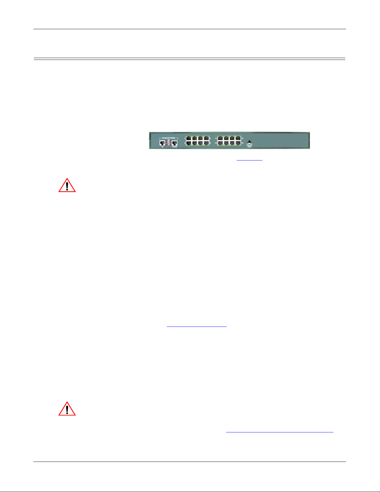
16-Port (DeviceMaster RTS - External Power Supply) Installation
Use the following procedure to install the DeviceMaster RTS 16-port with an
external power supply.
1. Place the DeviceMaster RTS on a stable surface, or optionally mount the
DeviceMaster in a rack.
Rack Installation:
a. Attach the L brackets to the interface using the screws supplied with the
unit.
b. You can mount the unit facing in either direction.
c. Attach the L bracket into your rack.
Follow these guidelines when mounting the DeviceMaster RTS in a
rack.
• If the DeviceMaster is installed in a closed or multi-rack assembly,
the operating temperature of the rack environment may be greater
than the ambient temperature. Be sure to install the DeviceMaster
in an environment that is compatible with the maximum rated
ambient temperature.
• Make sure that the mechanical loading is level to avoid a
hazardous condition; such as, loading heavy equipment in the rack
unevenly. The rack should safely support the combined weight of
all equipment in the rack.
• Slots and openings in the cabinet are provided for ventilation. To
ensure reliable operation of the DeviceMaster and to protect it from
overheating, maintain a minimum of 1 inch of clearance on all
sides of the unit.
• AC power inputs are intended to be used with a three-wire
grounding type plug, which has a grounding pin. Equipment
grounding ensures safe operation. Do not defeat the grounding
means and verify that the DeviceMaster is reliably grounded when
mounting within the rack.
Note: Do not connect multiple units until you have changed the default IP
2. Connect the DeviceMaster RTS to the same Ethernet network segment as the
3. Apply power to the DeviceMaster RTS by connecting the AC power adapter to
address, see Initial Configuration on Page 35.
host PC using one of the following methods.
• Ethernet hub or switch (10/100Base-T): Connect to the port labeled UP
on the DeviceMaster RTS using a standard Ethernet cable.
• Server NIC (10/100Base-T): Connect to the port labeled DOWN on the
DeviceMaster RTS using a standard Ethernet cable.
• Daisy-chaining DeviceMaster units: Connect the port labeled DOWN
on the first DeviceMaster RTS to the port labeled UP on the second
DeviceMaster or other device using a standard Ethernet cable.
Do not connect RS-422/485 devices until the appropriate port interface
type has been configured. The default port setting is RS-232.
the DeviceMaster, the power cord to the power adapter, and plugging the
power cord into a power source. See
External Power Supply Specifications on
Page 138 if you want to provide your own power supply.
28 - Hardware Installation DeviceMaster Installation and Configuration Guide: 2000594 Rev. A
Page 29

Hardware Installation
LNK
ACT
COL
100
10/100 NETWORK
UP DOWN
4. Verify that the PWR LED has completed the boot cycle and network
connection for the DeviceMaster RTS is functioning properly using the table
below.
DeviceMaster RTS 16-Port (External Power Supply) LED Descriptions
Red LED on the front panel of the DeviceMaster is lit, indicating you
have power and it has completed the boot cycle.
Red
LED
Note: The LED flashes while booting and it takes approximately 15
seconds for the Bootloader to complete the cycle. When the
Bootloader completes the cycle, the LED has a solid, steady light
that blinks approximately every 10 seconds.
LNK
ACT
COL
The red LNK ACT LED is lit, indicating that
you have a working Ethernet connection.
If the red COL LED is lit, there is a network
collision.
If the red 100 LED is lit, it indicates a
100
working 100 MB Ethernet connection (100
MB network, only). If the LED is not lit, it
indicates a 10 MB Ethernet connection.
Note: For additional LED information, go to the Status LED table on Page 150.
5. Go to Initial Configuration on Page 35 for default network settings and how to
configure the DeviceMaster for use.
DeviceMaster Installation and Configuration Guide: 2000594 Rev. A Hardware Installation - 29
Page 30

Hardware Installation
Caution
Caution
16-Port (DeviceMaster PRO) Installation
Use the following procedure to install the DeviceMaster PRO 16-port with an
external power supply.
1. Place the DeviceMaster PRO on a stable surface, or optionally mount the
DeviceMaster PRO in a rack.
Rack Installation:
a. Attach the L brackets to the DeviceMaster PRO using the screws supplied
with the unit.
b. You can mount the unit facing in either direction.
c. Attach the L bracket into your rack.
Follow these guidelines when mounting the DeviceMaster in a rack.
• If the DeviceMaster PRO is installed in a closed or multi-rack
assembly, the operating temperature of the rack environment may
be greater than the ambient temperature. Be sure to install the
DeviceMaster in an environment that is compatible with the
maximum rated ambient temperature.
• Make sure that the mechanical loading is level to avoid a
hazardous condition; such as, loading heavy equipment in the rack
unevenly. The rack should safely support the combined weight of
all equipment in the rack.
• Slots and openings in the cabinet are provided for ventilation. To
ensure reliable operation of the DeviceMaster and to protect it from
overheating, maintain a minimum of 1 inch of clearance on all
sides of the unit.
• AC power inputs are intended to be used with a three-wire
grounding type plug, which has a grounding pin. Equipment
grounding ensures safe operation. Do not defeat the grounding
means and verify that the DeviceMaster is reliably grounded when
mounting within the rack.
Note: Do not connect multiple units until you have changed the default IP
address, see
2. Connect the DeviceMaster PRO to the same Ethernet network segment as the
host PC using one of the following methods.
• Ethernet hub or switch (10/100Base-T): Connect to the port labeled UP
on the DeviceMaster PRO using a standard Ethernet cable.
• Server NIC (10/100Base-T): Connect to the port labeled DOWN on the
DeviceMaster PRO using a standard Ethernet cable.
• Daisy-chaining DeviceMaster units: Connect the port labeled DOWN
on the first DeviceMaster PRO to the port labeled UP on the second
DeviceMaster PRO or other device using a standard Ethernet cable.
Note: Do not connect multiple units until you have changed the default IP
If you plan on using the NS-Link device driver, make sure that you do
not connect RS-422/485 devices until the appropriate port interface
type has been configured in the driver. The NS-Link default port
setting is RS-232.
3. Connect the power cord into a power source.
4. Apply power to the DeviceMaster PRO by turning on the power switch.
Initial Configuration on Page 35.
address, see
Initial Configuration on Page 35.
30 - Hardware Installation DeviceMaster Installation and Configuration Guide: 2000594 Rev. A
Page 31

Hardware Installation
LNK/
ACT
COL
100
10/100NETWORK
UP DOWN
5. Verify that the PWR LED has completed the boot cycle and network
connection for the DeviceMaster is functioning properly using the table below.
DeviceMaster PRO 16-Port LED Description
Red LED on the front panel of the DeviceMaster PRO is lit,
Red
LED
(Front
panel)
indicating you have power and it has completed the boot cycle.
Note: The LED flashes while booting and it takes approximately 15
seconds for the Bootloader to complete the cycle. When the
Bootloader completes the cycle, the LED has a solid, steady
light that blinks approximately every 10 seconds.
LNK/
ACT
COL
The red LNK/ACT LED is lit, indicating
that you have a working Ethernet
connection.
If the red COL LED is lit, there is a
network collision.
If the red 100 LED is lit, it indicates a
working 100 MB Ethernet connection
100
(100 MB network, only). If the LED is not
lit, it indicates a 10 MB Ethernet
connection.
Note: For additional LED information, go to the Status LED table on Page 150.
6. Go to Initial Configuration on Page 35 for default network settings and how to
configure the DeviceMaster for use.
DeviceMaster Installation and Configuration Guide: 2000594 Rev. A Hardware Installation - 31
Page 32

Hardware Installation
Caution
16/32-Port Rack Mount Models (Internal Power Supply) Installation
Use the following procedure to install the DeviceMaster 16-port or 32-port with an
internal power supply.
1. Place the DeviceMaster on a stable surface, or optionally mount the
DeviceMaster in a rack.
Rack Installation:
a. Attach the L brackets to the interface using the screws supplied with the
unit.
b. You can mount the unit facing in either direction.
c. Attach the L bracket into your rack.
Follow these guidelines when mounting the DeviceMaster in a rack.
• If the DeviceMaster is installed in a closed or multi-rack assembly,
the operating temperature of the rack environment may be greater
than the ambient temperature. Be sure to install the DeviceMaster
in an environment that is compatible with the maximum rated
ambient temperature.
• Make sure that the mechanical loading is level to avoid a
hazardous condition; such as, loading heavy equipment in the rack
unevenly. The rack should safely support the combined weight of
all equipment in the rack.
• Slots and openings in the cabinet are provided for ventilation. To
ensure reliable operation of the DeviceMaster and to protect it from
overheating, maintain a minimum of 1 inch of clearance on all
sides of the unit.
• AC power inputs are intended to be used with a three-wire
grounding type plug, which has a grounding pin. Equipment
grounding ensures safe operation. Do not defeat the grounding
means and verify that the DeviceMaster is reliably grounded when
mounting within the rack.
Note: Do not connect multiple units until you have changed the default IP
address, see
Initial Configuration on Page 35.
32 - Hardware Installation DeviceMaster Installation and Configuration Guide: 2000594 Rev. A
Page 33

Hardware Installation
DeviceMaster RTS - Larger pictures, Page 147
DeviceMaster Serial Hub - Larger picture, Page 146
Caution
LNK/
ACT
Duplex
100
10/100ETHERNET
2. Connect the DeviceMaster port labeled 10/100 NETWORK to the same
Ethernet network segment as the host PC using a standard network cable.
If you plan on using the NS-Link device driver, make sure that you do
not connect RS-422/485 devices until the appropriate port interface
type has been configured in the driver. The NS-Link default port
setting is RS-232.
3. Apply power to the DeviceMaster by connecting the appropriate power cord
into the power socket on the DeviceMaster, plugging the power cord into a
power source, and turning on the power switch.
4. Verify that the Status LED has completed the boot cycle and network
connection for the DeviceMaster is functioning properly using the table below.
16/32-Port (Internal Power Supply) LED Descriptions
The amber Status LED on the device is lit, indicating you have power
and it has completed the boot cycle.
Status
LNK/
ACT
Duplex
Note: The Status LED flashes while booting and it takes approximately
The red LNK/ACT LED is lit, indicating that you
have a working Ethernet connection.
If the red Duplex LED is lit, it indicates full-duplex
activity.
If the red 100 LED is lit, it indicates a working 100
100
MB Ethernet connection (100 MB network, only). If
the LED is not lit, it indicates a 10 MB Ethernet
connection.
Note: The port LED activity may be inconsistent until the port has been opened.
After a port is opened, LED activity works as documented.
5. Go to Initial Configuration on Page 35 for default network settings and how to
configure the DeviceMaster for use.
15 seconds for the Bootloader to complete the cycle. When the
Bootloader completes the cycle, the LED has a solid, steady light
that blinks approximately every 10 seconds. For additional LED
information, go to the
Status LED table on Page 150.
DeviceMaster Installation and Configuration Guide: 2000594 Rev. A Hardware Installation - 33
Page 34

Hardware Installation
34 - Hardware Installation DeviceMaster Installation and Configuration Guide: 2000594 Rev. A
Page 35

Initial Configuration
There are several ways to configure network information. Comtrol Technical
Support recommends connecting the DeviceMaster to a PC or laptop running
Windows and installing PortVision DX for initial configuration.
Optionally, you can use RedBoot to configure the network address, see RedBoot
Procedures on Page 129.
This section shows how to use PortVision DX for initial DeviceMaster
configuration. It also defines requirements and how configuring DeviceMaster
security affects PortVision DX and shows you how to:
• Install PortVision DX
• Configure the network address (Page 40
• Check the SocketServer version on the DeviceMaster (Page 43
• If necessary, download the latest version SocketServer and upload it into the
DeviceMaster (Page 45
• Organize how PortVision DX displays your Comtrol Ethernet attached
products
• Access the latest documentation for your Comtrol Ethernet attached product
)
)
)
PortVision Plus
PortVision DX replaces PortVision Plus. PortVision Plus does not support:
• Operating systems above Windows 7
• SocketServer versions v9.00 or above
• NS-Link device driver v10.xx or above
PortVision DX Overview
PortVision DX automatically detects Comtrol Ethernet attached products
physically attached to the local network segment so that you can configure the
network address, upload firmware, and manage the following products:
• DeviceMaster family
- DeviceMaster PRO
- DeviceMaster RTS
- DeviceMaster Serial Hub
- DeviceMaster UP
- DeviceMaster 500
• DeviceMaster LT
•IO-Link Master
• RocketLinx switches
In addition to identifying Comtrol Ethernet attached products, you can use
PortVision DX to display any third-party switch and hardware that may be
connected directly to those devices. All non-Comtrol products and unmanaged
DeviceMaster Installation and Configuration Guide: 2000594 Rev. A Initial Configuration - 35
Page 36

PortVision DX Requirements
RocketLinx switches are treated as non-intelligent devices and have limited
feature support. For example, you cannot configure or update firmware on a thirdparty switch.
PortVision DX Requirements
Use PortVision DX to identify, configure, update, and manage the DeviceMaster on
the following Windows operating systems:
•Windows 8.1
•Windows 8
• Windows Server 2012
•Windows 7
• Windows Server 2008
•Windows Vista
• Windows Server 2003
•Windows XP
PortVision DX requires that you connect the Comtrol Ethernet attached product to
the same network segment as the Windows host system if you want to be able to
scan and locate it automatically during the configuration process.
Note: You must install PortVision DX v3.02 or higher to load firmware with a
.cmtl extension.
Configuring Security Settings and PortVision DX
The following list provides basic PortVision DX operations that are affected how
the DeviceMaster interacts with PortVision DX when security is enabled using the
web interface (SocketServer/NS-Link).
• PortVision DX must scan the DeviceMaster before configuring security.
• PortVision DX locates the DeviceMaster before setting either Secure Data Mode
or Secure Config Mode.
• If PortVision DX discovers the DeviceMaster after setting security, the
following conditions occur:
- A lock symbol displays before the Device Name.
- The IP address of the DeviceMaster does not display.
-The Software Settings and Web Interface tabs are not present in the
Properties page.
- The IP mode displays as DHCP without the ability to modify.
-The Upload and Reboot icons on the Launch Bar are grayed out and the
options are disabled in the popup menus.
Note: If the DeviceMaster was previously configured with security, PortVision DX
features are reduced.
36 - Initial Configuration DeviceMaster Installation and Configuration Guide: 2000594 Rev. A
Page 37

Installing PortVision DX
During initial configuration, PortVision DX automatically detects and identifies
DeviceMaster units, if they are in the same network segment.
Use the Software and Documentation CD that came with the DeviceMaster to
check for the latest version of PortVision DX or use the link below to download the
latest version.
1. Locate PortVision DX using one of the following methods to download the
latest version:
• Software and Documentation CD: You can use the CD menu system to
• FTP site subdirectory:
Note: Depending on your operating system, you may need to respond to a
2. Execute the PortVision_DX[version].msi file.
3. Click Next on the Welcome screen.
Installing PortVision DX
check the version on the CD against the latest released version.
ftp://ftp.comtrol.com/dev_mstr/portvision_dx
.
Security Warning to permit access.
4. Click I accept the terms in the License Agreement and Next.
DeviceMaster Installation and Configuration Guide: 2000594 Rev. A Initial Configuration - 37
Page 38

Installing PortVision DX
5. Click Next or optionally, browse to a different location and then click Next.
6. Click Next to configure the shortcuts.
7. Click Install.
38 - Initial Configuration DeviceMaster Installation and Configuration Guide: 2000594 Rev. A
Page 39

Installing PortVision DX
You can save time if you only scan for DeviceMasters.
8. Depending on the operating system, you may need to click Ye s to the Do you
want to allow the following program to install software on this computer?
query.
9. Click Launch PortVision DX and Finish in the last installation screen.
10. Depending on the operating system, you may need to click Ye s to the Do you
want to allow the following program to make changes to this computer? query.
11. Select the Comtrol Ethernet attached products that you want to locate and
then click Scan.
Note: If the Comtrol Ethernet attached product is not on the local segment and
it has been programmed with an IP address, it will be necessary to
manually add the Comtrol Ethernet attached product to PortVision DX.
12. Go to Step 6
the DeviceMaster network settings.
If you need additional information about PortVision DX, refer to the Help system.
DeviceMaster Installation and Configuration Guide: 2000594 Rev. A Initial Configuration - 39
in the next section, Configuring the Network Settings, to program
Page 40

Configuring the Network Settings
Default Network Settings
IP address:
192.168.250.250
Subnet mask:
255.255.0.0
Gateway address:
192.168.250.1
Note: If you do not have any RocketLinx managed switches or IO-Link
Masters, it saves scanning time if you do not scan for them.
If PortVision DX does not locate your DeviceMaster on the
network, make sure that you are using the latest version of
PortVision DX.
Configuring the Network Settings
Use the following procedure to change the default network settings on the
DeviceMaster for your network.
Note: Technical Support advises configuring one new DeviceMaster at a time to
avoid device driver configuration problems. If you want to configure
multiple DeviceMasters using the Assign IP to Multiple Devices option, see
Configuring Multiple DeviceMasters Network Addresses
The following procedure shows how to configure a single DeviceMaster connected
to the same network segment as the Windows system. If the DeviceMaster is not
on the same physical segment, you can add it manually using Adding a New
Device in PortVision DX on Page 105.
1. If you have not done so, install PortVision DX (Installing PortVision DX
Page 37).
2. Start PortVision DX using the PortVision DX desktop shortcut or from the Start
button, click All Programs > Comtrol > PortVision DX > PortVision DX.
3. Depending on your operating system, you may need to click Ye s to the Do you
want to allow the following program to make changes to this computer? query.
4. Click the Scan button in the Toolbar.
5. Click Scan to locate the Comtrol Ethernet attached products including the
DeviceMaster on the network.
on Page 105.
on
40 - Initial Configuration DeviceMaster Installation and Configuration Guide: 2000594 Rev. A
Page 41

Configuring the Network Settings
6. Highlight the DeviceMaster for which you want to program network
information and open the Properties screen using one of these methods.
• Double-click the DeviceMaster in the Device Tree or Device List pane.
• Highlight the DeviceMaster in the Device Tree or Device List pane and click
the Properties button.
• Right-click the DeviceMaster in the Device Tree or Device List pane and
click Properties in the popup menu
• Highlight the DeviceMaster, click the Manage menu and then Properties.
DeviceMaster Installation and Configuration Guide: 2000594 Rev. A Initial Configuration - 41
Page 42

Configuring the Network Settings
Note: SocketServer versions previous to v9.00 did not support the Bootloader
Timeout option in the PortVision DX Properties screen.
7. Optionally, rename the DeviceMaster in the Device Name field.
Note: The MAC address and Device Status fields are automatically populated and
you cannot change those values.
8. Optionally, enter the serial number, which is on a label on the DeviceMaster.
9. If necessary, you can change the Detection Type.
• REMOTE means that the DeviceMaster is not connected to this segment of
the network and it uses IP communications, not MAC communications.
• LOCAL means that the DeviceMaster is on this local network segment and
uses MAC communications. An IP address is not required but Technical
support recommends using an IP address.
10. Change the DeviceMaster network properties as required for your site.
• If you want to disable IP communications on the DeviceMaster, click
Disable IP.
• To use the DeviceMaster with DHCP, click DHCP IP, and make sure that
you provide the MAC address of the device to the network administrator.
Make sure that the administrator reserves the IP address, subnet mask
and gateway address of the DeviceMaster in the DHCP server.
• To program a static IP address, click Static IP and enter the appropriate
values for your site.
Note: For additional information, open the PortVision DX Help system.
11. Typically, the Bootloader Timeout value should be left to it’s default value. In
some situations, you may need to temporarily adjust the Bootloader Timeout to
a higher value during a firmware update.
42 - Initial Configuration DeviceMaster Installation and Configuration Guide: 2000594 Rev. A
Page 43

12. Click Apply Changes to update the network information on the DeviceMaster.
Note: If you are deploying multiple DeviceMasters that share common values,
you can save the configuration file and load that configuration onto
other DeviceMasters. See Using
Page 107 for more information.
13. Click Close to exit the Properties window.
14. Go to Checking the SocketServer Version
version. You should update SocketServer firmware before any further
configuration.
Checking the SocketServer Version
SocketServer refers to the web page that is integrated in the firmware that comes
pre-installed on your DeviceMaster platform, which provides an interface to TCP/
IP socket mode configuration and services. If you install an NS-Link device driver,
an NS-Link version of SocketServer loads on the DeviceMaster.
Note: Technical Support recommends that you update to the latest version of
SocketServer before installing an NS-Link device driver or configuring
socket ports.
Use the following procedure to check the SocketServer version on the
DeviceMaster and check the ftp site for the latest version.
1. If necessary, open PortVision DX > Start/Programs > Comtrol > PortVision DX >
PortVision DX or use the desktop shortcut and scan the network.
2. Check the SocketServer version number of the Software Version for the
DeviceMaster.
Checking the SocketServer Version
SocketServer Configuration Files on
on Page 43 to check the SocketServer
DeviceMaster Installation and Configuration Guide: 2000594 Rev. A Initial Configuration - 43
Page 44

Checking the SocketServer Version
3. Check the Comtrol ftp site to see if a later version is available by accessing the
ftp subdirectory that contains the latest version of SocketServer.
• View an ftp subdirectory that contains the latest version of SocketServer:
ftp://ftp.comtrol.com/dev_mstr/rts/software/socketserver
.
Note: The DeviceMaster PRO, DeviceMaster RTS, DeviceMaster Serial Hub,
and DeviceMaster 500 all use the same firmware, although the above
paths point to the location of the DeviceMaster RTS file.
4. If the version on the web site is later than the version on the DeviceMaster,
download the file, and then go to Uploading SocketServer with PortVision DX
on Page 45.
If the SocketServer version on the DeviceMaster is current, you are ready to
continue the installation and configuration process.
44 - Initial Configuration DeviceMaster Installation and Configuration Guide: 2000594 Rev. A
Page 45

Uploading SocketServer with PortVision DX
Optionally, you can highlight the DeviceMaster and
click the Upload button in the Launch bar.
Use this section to upload a newer version of SocketServer on the DeviceMaster
using PortVision DX. Technical Support recommends updating SocketServer
before any further configuration to avoid configuration problems.
You can use this procedure if your DeviceMaster is connected to the host PC,
laptop, or if the DeviceMaster resides on the local network segment.
1. Make sure that you have downloaded the latest SocketServer version from:
ftp://ftp.comtrol.com/dev_mstr/rts/software/socketserver
2. If necessary, open PortVision DX > Start/Programs > Comtrol > PortVision DX >
PortVision DX or use the desktop shortcut.
3. Right-click the DeviceMaster or DeviceMasters for which you want to update,
click Advanced > Upload Firmware, browse to the SocketServer .cmtl file, and
then click Open.
Uploading SocketServer with PortVision DX
.
If the Detection Type is set to REMOTE, you may want to change it to LOCAL.
The DeviceMaster Status on a DeviceMaster that is set to REMOTE displays
in blue: ON-LINE (TCP).
DeviceMaster Installation and Configuration Guide: 2000594 Rev. A Initial Configuration - 45
Page 46

Uploading SocketServer with PortVision DX
4. Click Ye s to the Upload Firmware message that warns you that this is a
sensitive process. It may take a few moments for the firmware to upload onto
the DeviceMaster. The DeviceMaster reboots itself during the upload process.
5. Click Ok to the advisory message about waiting to use the device until the
status reads ON-LINE. In the next polling cycle, PortVision DX updates the
Device List pane and displays the new SocketServer version or right-click the
DeviceMaster and click Refresh.
6. If the upload fails, reset the Bootloader timeout to 60 seconds and then repeat
Steps 3
Page 115.
You are now ready to continue the installation and configuration process.
• Device Driver (NS-Link) Installation
• Socket Port Configuration
through 5. For procedures, see Changing the Bootloader Timeout on
on Page 51
on Page 65
46 - Initial Configuration DeviceMaster Installation and Configuration Guide: 2000594 Rev. A
Page 47

Customizing PortVision DX
You can customize how PortVision DX displays the devices. You can even create
sessions tailored for specific audiences. You can also add shortcuts to other
applications using Tools > Applications > Customize feature.
The following illustrates how you can customize your view.
Customizing PortVision DX
See the PortVision DX Help system for detailed information about modifying the
view. For example, the above screen shot illustrates devices layered in folders.
DeviceMaster Installation and Configuration Guide: 2000594 Rev. A Initial Configuration - 47
Page 48

Accessing DeviceMaster Documentation from PortVision DX
Accessing DeviceMaster Documentation from PortVision DX
You can use this procedure in PortVision DX to download and open the previously
downloaded documents for the DeviceMaster. You can also check to see if you have
the latest version of the documentation using PortVision DX.
How to Download Documentation
Use this procedure to initially download a document or documents.
1. If necessary, open PortVision DX > Start/Programs >
Comtrol > PortVision DX > PortVision DX or use the
desktop shortcut.
2. Click Help > Documentation.
3. Optionally, click the DOWNLOAD THE CURRENT
DOCUMENTATION CATALOG ONLINE button to
make sure that the latest documentation is available
to PortVision DX.
4. Select the product Category from the drop list.
5. Select the document you want to download from the Documentation drop list.
6. Click the Download the latest edition from the web button.
Note: It may take a few minutes to download, depending on your connection
speed. The document opens automatically after it has downloaded.
7. Click Close if you have downloaded all of the documents that you wanted.
48 - Initial Configuration DeviceMaster Installation and Configuration Guide: 2000594 Rev. A
Page 49

How to Open Previously Downloaded Documents
How to Open
Previously
Downloaded
Documents
Use the following procedure to access previously downloaded documents in
PortVision DX.
Note: Optionally, you can browse to the Program Files (x86) > Comtrol > PortVision
DX > Docs subdirectory and open the document.
1. If necessary, open PortVision DX > Start/Programs > Comtrol > PortVision DX >
PortVision DX or use the desktop shortcut.
2. Click Help > Documentation.
3. Click the Open the local copy of the document button to view the document.
Note: If the document fails to open, it may be that your browser has been
disabled. You can still access the document by clicking the Browse the
folder for already downloaded documentation button and opening the
document with your custom browser.
4. Click Close in the Documentation... popup, unless you want to open or
download other documents.
DeviceMaster Installation and Configuration Guide: 2000594 Rev. A Initial Configuration - 49
Page 50

How to Open Previously Downloaded Documents
50 - Initial Configuration DeviceMaster Installation and Configuration Guide: 2000594 Rev. A
Page 51

Overview
Device Driver (NS-Link) Installation
This section discusses the following topics:
• Linux Installations on Page 52
• Windows Installations on Page 53
The following subsections discuss procedures that need to be done before
installing and configuring the NS-Link device driver.
Before Installing the NS-Link Driver
Before installing the NS-Link device driver for the Linux and Windows operating
systems, the following conditions must be met:
• The DeviceMaster is connected to the network and powered on (Hardware
Installation on Page 15).
• The network information has been configured in the DeviceMaster
(Configuring the Network Settings on Page 40).
• Checked to see if the latest version of SocketServer resides on the
DeviceMaster (
DX or you can open your browser, enter the DeviceMaster IP address to view
the version on the Server Status page.
• If necessary, uploaded the latest version of SocketServer (Uploading
SocketServer with PortVision DX on Page 45.
Note: Technical Supports recommends that you update to the latest version of
SocketServer before installing any NS-Link device driver.
After NS-Link driver installation and configuration, the same ports can be
configured as TCP/IP sockets using an NS-Link version of the SocketServer web
page (Socket Port Configuration
Checking the SocketServer Version on Page 43 using PortVision
on Page 65).
DeviceMaster Installation and Configuration Guide: 2000594 Rev. A Device Driver (NS-Link) Installation - 51
Page 52

Linux Installations
Linux Installations
You can locate the latest device driver for Linux using one of these methods:
• Download the latest device driver: ftp://ftp.comtrol.com/dev_mstr/rts/
drivers/linux.
Note: Although the ftp link displays rts in the path, the driver supports the
DeviceMaster models discussed in this User Guide.
• Software and Documentation CD: You can use the CD to check the driver
version on the CD against the latest released version. Open the /html/
default.htm file to use the menu system, which provides you with links to
download all software and documents.
Refer to the README file packaged with the Linux driver for driver installation
and configuration procedures.
Before you install the Linux NS-Link device driver:
1. Make sure that you have programmed an appropriate network address into
the DeviceMaster.
2. Make sure that you verify that you have the latest version of SocketServer
loaded on the DeviceMaster.
If you do not want to install PortVision DX (Page 37) to check the SocketServer
version, you can:
a. Open SocketServer to check the version by opening your browser and
entering the IP address of the DeviceMaster.
b. Check the ftp site for the latest version: ftp://ftp.comtrol.com/dev_mstr/rts/
software/SocketServer.
c. If necessary, download the latest version.
Note: Technical Supports recommends that you update to the latest version of
SocketServer before installing an NS-Link device driver.
3. Install and configure the Linux device driver using the Readme file packaged
with the driver.
52 - Device Driver (NS-Link) Installation DeviceMaster Installation and Configuration Guide: 2000594 Rev. A
Page 53

Windows Installations
This subsection provides an installation overview for the NS-Link device driver for
Windows. For detailed installation and configuration information, see the
DeviceMaster Device Driver (NS-Link) User Guide for Windows
on the Software and Documentation CD or you can download
Windows Installations
, which is available
the latest.
Supported Operating Systems
Installation Overview for Windows
The NS-Link device driver for Windows supports:
• Windows 8/8.1
• Windows Server 2012
• Windows 7
• Windows Server 2008
• Windows Vista
• Windows Server 2003
• Window XP
If you are updating the driver or need to remove the NS-Link device driver, you
can refer to the DeviceMaster Device Driver (NS-Link) User Guide
or the help
system.
Note: Administrative privileges are required to install device drivers on Windows
systems (excluding Windows Server 2003 and Windows XP).
The following NS-Link device driver installation and configuration procedures are
discussed in this subsection:
• Install the NS-Link device driver and Comtrol Drivers Management Console
using the Installation Wizard.
• Configure the COM ports using the Comtrol Drivers Management Console.
• Configure device properties using the Comtrol Drivers Management Console.
NS-Link for Windows Installation
1. If necessary, locate the NS-Link device driver and make it available to the host
system. The driver assembly is available on the Software and Documentation
CD if you do not have internet access, or download the latest driver from:
ftp://ftp.comtrol.com/dev_mstr/rts/drivers/win7.
Note: Although the ftp link displays win7 in the path, the driver supports the
previously listed
Windows operating systems.
2. Execute the driver assembly DeviceMaster_Windows_x.xx.exe file and click
Next to start the installation.
DeviceMaster Installation and Configuration Guide: 2000594 Rev. A Device Driver (NS-Link) Installation - 53
Page 54

NS-Link for Windows Installation
3. Click Next to install in the default location.
4. Click Install
5. Leave the Launch
DeviceMaster Driver
Installation box
checked.
If you do not check
this box, you can use
the shortcut under the
Start button at:
Programs > Comtrol >
DeviceMaster >
DeviceMaster Driver
Installation Wizard.
6. Click Finish to
complete the
installation of the
wizard.
54 - Device Driver (NS-Link) Installation DeviceMaster Installation and Configuration Guide: 2000594 Rev. A
Page 55

7. Click Next to start the driver installation.
8. Click Install and Next.
NS-Link for Windows Installation
DeviceMaster Installation and Configuration Guide: 2000594 Rev. A Device Driver (NS-Link) Installation - 55
Page 56

NS-Link for Windows Installation
9. Select the DeviceMaster model that you are installing from the list.
10. Enter the quantity of this DeviceMaster model that you want to install and
click Ok.
11. Repeat Steps 9 and 10 for each DeviceMaster that you are installing and click
Next.
12. Click Proceed.
You may see the popup at the right for each port.
56 - Device Driver (NS-Link) Installation DeviceMaster Installation and Configuration Guide: 2000594 Rev. A
Page 57

NS-Link for Windows Installation
13. Return to the Installation Wizard and click Close.
14. Go to the next subsection for NS-Link driver configuration procedures.
DeviceMaster Installation and Configuration Guide: 2000594 Rev. A Device Driver (NS-Link) Installation - 57
Page 58

Configuring the NS-Link Driver for Windows
Configuring the NS-Link Driver for Windows
This subsection provides a configuration overview for the NS-Link driver. For
detailed information or if the DeviceMaster is on a different physical segment,
refer to the help system or the DeviceMaster Device Driver (NS-Link) User Guide,
which is available on the Software and Documentation CD or you can download
the latest.
The DeviceMaster must be connected to the local network segment or directly to a
NIC on the host system to operate in MAC mode to perform the following
configuration steps.
1. Access the Comtrol Drivers Management Console using the desktop shortcut
or Start > Programs > Comtrol > DeviceMaster > DeviceMaster Driver Management
Console.
2. Highlight the Device Name of the DeviceMaster that you want to configure.
3. Select the MAC address from the drop-down list or enter the address from the
MAC address label on the DeviceMaster. If you programmed the IP address
using PortVision DX, the IP address displays in the IP Mode text box after you
select the MAC address.
Note: If you enter the MAC address, make sure that you use the correct format:
00 C0 4E xx xx xx. A space must separate each pair of digits. The MAC
address is located on a label on the DeviceMaster or you can view it
using PortVision DX.
If the appropriate MAC address is not displayed in the drop-down list, then it
can be one of the following reasons:
• Not on the same network segment
• DeviceMaster not powered on or connected
• The wrong DeviceMaster model was selected during the driver installation
• Device failure
58 - Device Driver (NS-Link) Installation DeviceMaster Installation and Configuration Guide: 2000594 Rev. A
Page 59

Configuring the NS-Link Driver for Windows
4. Click Apply to program the driver with the MAC address of the DeviceMaster
or Ok to save the change and close the Comtrol Drivers Management Console.
If you do not Apply the changes before leaving this screen, you will be
prompted to Apply, Ignore, or Cancel the changes.
5. Now that the MAC address has been associated to the DeviceMaster, you can
use the Network Settings screen to:
• Change the IP address, set the DeviceMaster to DHCP, or Disable IP
communications using the Network Settings button
• Reboot the DeviceMaster on the General tab
• Access network statistics on the Advanced tab
If you want use IP mode and the IP address is configured for your network,
click the IP Mode radio button and click Apply. If you want to use SSL Mode,
you must set the DeviceMaster to IP mode.
Click the Network Settings button and click Modify to make any network
settings changes for DHCP or MAC mode (Disable IP).
6. Optionally, click Enable SSL Mode if you want to configure secure COM ports.
The DeviceMaster must be configured using IP Mode before you can Enable
SSL Mode.
If SSL Mode is enabled, TCP connections that carry data to/from the serial
ports are encrypted using SSL or TLS security protocols. This includes the
following:
• TCP connections to the per-serial-port TCP ports (default is 8000, 8001,
8002, ...) are encrypted using SSL/TLS.
• TCP connections to TCP port 4606 on which the DeviceMaster implements
the Comtrol proprietary serial driver protocol are encrypted using SSL/
TLS.
• Since SSL/TLS can not be used for either UDP data streams or for the
Comtrol proprietary MAC mode Ethernet driver protocol, both UDP and
MAC mode serial data transport features are disabled.
DeviceMaster Installation and Configuration Guide: 2000594 Rev. A Device Driver (NS-Link) Installation - 59
Page 60

Configuring the NS-Link Driver for Windows
In addition to encrypting the data streams, it is possible to configure the
DeviceMaster so that only authorized client applications can connect using
SSL/TLS.
For this option to function, you must also Enable Secure Data Mode
Link web page.
Note: See the help system or the DeviceMaster NS-Link User Guide for
Windows if you need additional information on SSL and the
corresponding options.
7. If you are using a server certificate, click the Server Certificate check box and
enter the name in the Server Certificate text box.
8. If you are using a client certificate, click the drop list and browse to the
appropriate client certificate file.
9. Configure the device properties:
a. If desired, change the User-Friendly Device Name.
b. Optionally, set a different Keep Alive Timeout period. You can set the
amount of time in seconds that this DeviceMaster waits until it closes this
connection and frees all the ports associated with it.
c. Optionally, set the TCP Timeout Multiplier value.
d. Optionally, click a different Scan Rate (ms).
e. Optionally, click Verbose Event Log if you want to log additional
DeviceMaster information into the event log.
f. After making your changes, click Apply if you have additional
configuration procedures or click Ok if you have completed configuring
your DeviceMaster.
Note: You can refer to the help system if you need information about any of the
options or features.
10. Optionally, you can click the Advanced tab and verify that the Device Status
message indicates that the DeviceMaster is active and Ok.
11. Go to the next subsection to configure COM port properties.
in the NS-
60 - Device Driver (NS-Link) Installation DeviceMaster Installation and Configuration Guide: 2000594 Rev. A
Page 61

Configuring COM Port Properties for Windows
The following is a COM port properties configuration overview. Use the
DeviceMaster Device Driver (NS-Link) User Guide
NS-Link Help system for detailed configuration information.
1. Highlight the first port you want to configure.
Configuring COM Port Properties for Windows
(also available on the CD) or the
2. Complete the screen appropriately for the serial device that you plan on
connecting to the port and click Ok.
a. Select the appropriate communications mode.
b. Enable the features that you want to use.
c. Optionally, click the RTS
Toggle Options button:
• If your communications
application does not toggle
RTS when transmitting in
RS-485 mode.
• If you are using an
external RS-232 to RS-485
converter, which is
attached to a port that is
configured for RS-232.
d. Click the appropriate options
for your environment.
e. Click OK to save the changes and return to the port General tab.
3. If desired, click the Clone check box to set all of the ports on this DeviceMaster
to these characteristics.
4. Optionally, change the User-Friendly Port Name.
5. If desired, select a different COM Name (COM port number). The drop-down
list displays (in use) next to COM port numbers that are already in use in this
system. Do not duplicate COM port numbers as this will cause the ports to not
function.
DeviceMaster Installation and Configuration Guide: 2000594 Rev. A Device Driver (NS-Link) Installation - 61
Page 62

Enabling Secure Data Mode
6. Click Apply to save these changes.
Note: If you selected RS-422 mode, make sure that there is not a device
7. Highlight the next port that you want to configure and perform Steps 1
through 6.
8. Refer to Connecting Serial Devices on Page 91 to attach your serial device.
9. Optionally, you may need to configure one or more ports for socket mode
(Socket Port Configuration on Page 65).
Enabling Secure Data Mode
In addition to enabling SSL mode in the driver, you must Enable Secure Data Mode
in the NS-Link web page. Use the following procedure to implement the Enable
Secure Data Mode option.
1. Access the NS-Link web page using one of these methods:
• Open your web browser, enter the IP address, and press Enter.
• Right-click the DeviceMaster in the Device List pane in PortVision DX and
click Webpage.
2. Click the Security tab.
3. Click Enable Secure Data Mode and Save.
attached to the port and click Ok.
62 - Device Driver (NS-Link) Installation DeviceMaster Installation and Configuration Guide: 2000594 Rev. A
Page 63

Enabling Secure Data Mode
4. Configure your security key and certificate and click Set.
Click the Help button if you need information about key and certificate
management.
DeviceMaster Installation and Configuration Guide: 2000594 Rev. A Device Driver (NS-Link) Installation - 63
Page 64

Enabling Secure Data Mode
64 - Device Driver (NS-Link) Installation DeviceMaster Installation and Configuration Guide: 2000594 Rev. A
Page 65

Socket Port Configuration
This section provides an overview of SocketServer and provides basic operating
procedures. SocketServer and DeviceMaster security are discussed in detail in
DeviceMaster Security on Page 69.
Note: Technical Supports recommends that you update to the latest version of
SocketServer Overview
SocketServer is the name of the TCP/IP socket web page that is integrated in the
firmware that comes pre-installed on your DeviceMaster. When you install an
Link device driver, an NS-Link version of SocketServer loads on the DeviceMaster.
The SocketServer home page (Server Status) provides access to configure.
• Socket port characteristics for:
• Network settings (after initial configuration)
• Security, which is discussed in detail starting on Page 69
• Email notification services
• RFC1006 (ISO over TCP)
Note: For socket service configuration procedures or detailed information each
SocketServer before installing an NS-Link device driver or configuring
socket ports.
NS-
- Serial
-TCP connection
-UDP connection
See SocketServer Architecture on Page 66 for more information about socket
port support.
field, see the web page Help system.
Web Page Help System
DeviceMaster Installation and Configuration Guide: 2000594 Rev. A Socket Port Configuration - 65
The web page Help system is available separately for your convenience. The web
page Help system contains detailed information and configuration procedures for
each mode discussed in
The Help system for the web page is available on the CD on the Supporting
Documents page for your DeviceMaster or you can download the latest version
from:
ftp://ftp.comtrol.com/dev_mstr/rts/software/socketserver/help/ssvr_help.zip.
To use the help system:
1. Unzip the files in a folder.
2. Open the ssvr_help.htm file.
3. Use your browser find function to locate the option or information for which
are searching.
SocketServer Architecture on Page 66.
Page 66

SocketServer Architecture
PC or
Mainframe
LAN/WAN
Ethernet Hub
DeviceMaster
Serial Device
IP socket
application
Ethernet Hub
TCP/IP Socket Mode
DeviceMaster
DeviceMaster
Ethernet Hub
Ethernet Hub
Dumb Terminal
Printer
Serial Tunneling Mode
LAN/WAN
UDP Mode
DeviceMaster
Ethernet Hub
Ethernet Hub
LAN/WAN
1234
Serial Device
In this example, four
PCs receive data
simultaneously from one
serial device.
DeviceMaster
Serial RS-232 connections
SocketServer
Architecture
TCP/IP socket mode operation is used to connect serial devices with an
application that supports TCP/IP socket communications addressing.
Serial tunneling mode is used to establish a socket connection between two
DeviceMasters through an Ethernet network.
UDP mode is designed for applications that need faster data transmission, or that
make use of UDP’s broadcast capabilities. UDP differs from TCP in that a UDP
transmission does not first require a connection to be opened before sending data
and the receiving device does not issue acknowledgements to the sender.
66 - Socket Port Configuration DeviceMaster Installation and Configuration Guide: 2000594 Rev. A
Page 67

Accessing Socket Configuration
Accessing Socket Configuration
There are several ways to access the socket configuration pages. Use the method
that fits your environment best.
• Web Browser
• PortVision DX
Web Browser To access the socket configuration page for the DeviceMaster using a web browser,
follow this procedure.
1. Start your web browser.
2. Enter the IP address of the DeviceMaster in the URL field.
Note: If you do not know the IP address, you can view the IP address in
3. Click the port number that you want to configure socket port settings (serial,
TCP connection configuration, and UDP connection configuration).
Note: See the web page Help system, if you need information about configuring
4. Click Save to return to the Server Status page.
5. Optionally, access the following pages to configure additional settings:
a. Click the Network tab to change the network settings.
b. Click the Security tab to enable DeviceMaster security.
c. Click the Email tab to configure email notification services.
d. Click the RFC1006 tab to configure RFC1006 settings.
PortVision DX.
sockets or serial tunneling, which contains detailed configuration
procedures and descriptions for all fields. See
Web Page Help System on
Page 65 for information about downloading the help file separately.
PortVision DX There are several ways to access the socket configuration page for the
DeviceMaster using PortVision DX.
1. If necessary, start PortVision DX, right-click the DeviceMaster that you want
to configure, and click Webpage.
2. Click the port for which you want to configure socket port settings (serial, TCP
connection configuration, and UDP connection configuration).
Note: For socket configuration information see the Help system. Click the ? in
a configuration area for field specific information or the Help button at
the bottom of the page to view page level help. To locate configuration
procedures, scroll to the top of the Help file and view the Table of
Contents.
3. Click Save to return to the Server Status (main) page.
4. Optionally, access the following pages to configure additional settings.
e. Click the Network tab to change the network settings.
f. Click the Security tab to enable DeviceMaster security.
g. Click the Email tab to configure email notification services.
h. Click the RFC1006 tab to configure RFC1006 (ISO over TCP) settings.
DeviceMaster Installation and Configuration Guide: 2000594 Rev. A Socket Port Configuration - 67
Page 68

SocketServer Versions
You r SocketServer or NS-Link version may be different than these examples.
These examples illustrate NS-Link and SocketServer v9.35 or higher.
The top illustration shows the web page before an NS-Link device driver
installation and the bottom illustration shows the web page after a device
driver installation.
SocketServer Versions
The SocketServer Overview discusses the that the default SocketServer web page
is the same as the NS-Link web page. If the NS-Link driver is not running (not
installed or disabled), SocketServer loads when you open a web browser session.
68 - Socket Port Configuration DeviceMaster Installation and Configuration Guide: 2000594 Rev. A
Page 69

DeviceMaster Security
This subsection provides a basic understanding of the DeviceMaster security
options, and the repercussions of setting these options. See
DeviceMaster Security Features on Page 171 if you need to reset DeviceMaster
security options. See Returning the DeviceMaster to Factory Defaults on Page 173
if you want to return the DeviceMaster settings to their default values.
Understanding Security Methods and Terminology
The following table provides background information and definitions.
Removing
Term or
Issue
If configured with a CA certificate, the DeviceMaster requires all SSL/TLS
clients to present an RSA identity certificate that has been signed by the
configured CA certificate. As shipped, the DeviceMaster is not configured with
a CA certificate and all SSL/TLS clients are allowed.
CA (Client
Authentication
certificate)
Client
Authentication
DH Key Pair
Used by SSL
Servers
† All DeviceMaster units are shipped from the factory with identical configurations. They all
†
have the identical, self-signed, Comtrol Server RSA Certificates, Server RSA Keys, Server DH
Keys, and no Client Authentication Certificates. For maximum data and access security, you
should configure all DeviceMaster units with custom certificates and keys.
This uploaded CA certificate that is used to validate a client's identity is
sometimes referred to as a trusted root certificate, a trusted authority
certificate, or a trusted CA certificate. This CA certificate might be that of a
†
trusted commercial certificate authority or it may be a privately generated
certificate that an organization creates internally to provide a mechanism to
control access to resources that are protected by the SSL/TLS protocols.
See Key and Certificate Management
section does not discuss the creation of CA Certificates.
A process using paired keys and identity certificates to prevent unauthorized
access to the DeviceMaster. Client authentication is discussed in Client
Authentication on Page 79 and Changing Keys and Certificates on Page 89.
This is a private/public key pair that is used by some cipher suites to encrypt
the SSL/TLS handshaking messages. Possession of the private portion of the
key pair allows an eavesdropper to decrypt traffic on SSL/TLS connections
that use DH encryption during handshaking.
The DH (Diffie-Hellman) key exchange, also called exponential key exchange,
is a method of digital encryption that uses numbers raised to specific powers
to produce decryption keys on the basis of components that are never directly
transmitted, making the task of a would-be code breaker mathematically
overwhelming.
The most serious limitation of Diffie-Hellman (DH key) in its basic or pure
form is the lack of authentication. Communications using Diffie-Hellman all
by itself are vulnerable to man in the middle attacks
should be used in conjunction with a recognized authentication method such
as digital signatures to verify the identities of the users over the public
communications medium.
See Certificates and Keys
Page 86 for more information.
on Page 79 and Key and Certificate Management on
Explanation
on Page 86 for more information. This
. Ideally, Diffie-Hellman
DeviceMaster Installation and Configuration Guide: 2000594 Rev. A DeviceMaster Security - 69
Page 70

Understanding Security Methods and Terminology
Term or
Issue
Digital
Certificate
PKI (public
key
infrastructure)
Explanation
A digital certificate is an electronic credit card that establishes your
credentials when doing business or other transactions on the Web. It is issued
by a certification authority (CA). It contains your name, a serial number,
expiration dates, a copy of the certificate holder's public key (used for
encrypting messages and digital signatures), and the digital signature of the
certificate-issuing authority so that a recipient can verify that the certificate is
real. Some digital certificates conform to a standard, X.509. Digital certificates
can be kept in registries so that authenticating users can look up other users'
public keys.
See Key and Certificate Management
on Page 86 for more information.
A public key infrastructure (PKI) enables users of a basically unsecure public
network such as the Internet to securely and privately exchange data and
money through the use of a public and a private cryptographic key pair that is
obtained and shared through a trusted authority. The public key
infrastructure provides for a digital certificate that can identify an individual
or an organization and directory services that can store and, when necessary,
revoke the certificates. Although the components of a PKI are generally
understood, a number of different vendor approaches and services are
emerging. Meanwhile, an Internet standard for PKI is being worked on.
The public key infrastructure assumes the use of public key cryptography,
which is the most common method on the Internet for authenticating a
message sender or encrypting a message. Traditional cryptography has
usually involved the creation and sharing of a secret key for the encryption
and decryption of messages. This secret or private key system has the
significant flaw that if the key is discovered or intercepted by someone else,
messages can easily be decrypted. For this reason, public key cryptography
and the public key infrastructure is the preferred approach on the Internet.
(The private key system is sometimes known as symmetric cryptography and
the public key system as asymmetric cryptography.)
A public key infrastructure consists of:
• A certificate authority (CA) that issues and verifies digital certificate. A
certificate includes the public key or information about the public key
• A registration authority (RA) that acts as the verifier for the certificate
authority before a digital certificate is issued to a requestor
• One or more directories where the certificates (with their public keys) are
held
• A certificate management system
For more information, see SSL Authentication on Page 78, SSL Performance
on Page 80, SSL Cipher Suites
on Page 81, and DeviceMaster Supported
Cipher Suites on Page 81.
70 - DeviceMaster Security DeviceMaster Installation and Configuration Guide: 2000594 Rev. A
Page 71

Understanding Security Methods and Terminology
Term or
Issue
RSA Key Pair†
SSH (Secure
Shell)
SSL (Secure
Sockets Layer)
Explanation
This is an algorithm for public-key cryptography. It is the first algorithm
known to be suitable for signing as well as encryption. RSA is widely used in
electronic commerce protocols, and is believed to be sufficiently secure given
sufficiently long keys and the use of up-to-date implementations. The system
includes a communications channel coupled to at least one terminal having an
encoding device, and to at least one terminal having a decoding device.
• Public key is a value provided by some designated authority as an
encryption key that, combined with a private key derived from the public
key, can be used to effectively encrypt messages and digital signatures.
•Private Key
- One half of the key pair used in conjunction with a public key
- Both the public and the private keys are needed for encryption /
decryption but only the owner of a private key ever needs to know it.
Using the RSA system, the private key never needs to be sent across
the Internet.
- The private key is used to decrypt text that has been encrypted with
the public key.
Thus, if User A sends User B a message, User A can find out User B’s
public key (but not User B’s private key) from a central administrator
and encrypt a message to User B using User B’s public key. When User
B receives it, User B decrypts it with User B’s private key. In addition
to encrypting messages (which ensures privacy), User B can
authenticate User B to User A (so that User A knows that it is really
User B who sent the message) by using User B’s private key to encrypt
a digital certificate.
See Key and Certificate Management on Page 86 for more information.
Secure Shell (SSH) allows data to be exchanged using a secure channel
between two networked devices. Replaces telnet which has no security. SSH
requires password authentication – even if password is empty.
See SSH Server
on Page 77 for more information.
The Secure Sockets Layer (SSL) is the predecessor of (TLS) Transport Layer
Security.
SSL is a commonly-used protocol for managing the security of a message
transmission on the Internet. SSL has recently been succeeded by Transport
Layer Security (TLS), which is based on SSL. SSL uses a program layer
located between the Internet's Hypertext Transfer Protocol (HTTP) and
Transport Control Protocol (TCP) layers.
SSL is included as part of both the Microsoft and Netscape browsers and most
Web server products. Developed by Netscape, SSL also gained the support of
Microsoft and other Internet client/server developers as well and became the
de facto standard until evolving into Transport Layer Security.
SSL uses the public-and-private key encryption system from RSA, which also
includes the use of a digital certificate.
See Pages 78 through 81 for detailed information about SSL.
Note: Two slightly different SSL protocols are supported by the DeviceMaster:
SSLv3 and TLSv1.
DeviceMaster Installation and Configuration Guide: 2000594 Rev. A DeviceMaster Security - 71
Page 72

Understanding Security Methods and Terminology
Term or
Issue
TLS
(Transport
Layer
Security)
Secure Data
Mode
Secure Config
Mode
Secure Monitor
Data Mode via
Tel ne t
Man in the
Middle attack
How Public
and Private
Key
Cryptography
Works
Explanation
Transport Layer Security (TLS) is a protocol that ensures privacy between
communicating applications and their users on the Internet. When a server
and client communicate, TLS ensures that no third party may eavesdrop or
tamper with any message. TLS is the successor to the Secure Sockets Layer
(SSL).
TLS and SSL are not interoperable. The TLS protocol does contain a
mechanism that allows TLS implementation to back down to SSL 3.0.
TCP connections that carry data to/from the DeviceMaster serial ports are
encrypted using SSL or TLS security protocols. See Security Modes
and Configure/Enable Security Features Overview
on Page 83 for more
on Page 75
information.
Unencrypted access to administrative and diagnostic functions are disabled.
See Security Modes
on Page 75 and Configure/Enable Security Features
Overview on Page 83 for more information.
Allows monitoring of a single serial port on the DeviceMaster while the port is
configured for Secure Data Mode. For more information see, the Enable
Monitoring Secure Data via Telnet option on Page 84.
A man in the middle attack is one in which the attacker intercepts messages
in a public key exchange and then retransmits them, substituting his own
public key for the requested one, so that the two original parties still appear to
be communicating with each other.
The attack gets its name from the ball game where two people try to throw a
ball directly to each other while one person in between them attempts to catch
it. In a man in the middle attack, the intruder uses a program that appears to
be the server to the client and appears to be the client to the server. The attack
may be used simply to gain access to the message, or enable the attacker to
modify the message before retransmitting it.
In public key cryptography, a public and private key are created
simultaneously using the same algorithm (a popular one is known as RSA) by
a certificate authority (CA).
The private key is given only to the requesting party and the public key is
made publicly available (as part of a digital certificate) in a directory that all
parties can access.
The private key is never shared with anyone or sent across the Internet. You
use the private key to decrypt text that has been encrypted with your public
key by someone else (who can find out what your public key is from a public
directory).
Thus, if User A sends User B a message, User A can find out User B’s public
key (but not User B’s private key) from a central administrator and encrypt a
message to User B using User B’s public key. When User B receives it, User B
decrypts it with User B’s private key. In addition to encrypting messages
(which ensures privacy), User B can authenticate User B to User A (so User A
knows that it is really User B who sent the message) by using User B’s private
key to encrypt a digital certificate. When User A receives it, User A can use
User B’s public key to decrypt it.
72 - DeviceMaster Security DeviceMaster Installation and Configuration Guide: 2000594 Rev. A
Page 73

Understanding Security Methods and Terminology
Term or
Issue
Explanation
A number of products are offered that enable a company or group of companies
to implement a PKI. The acceleration of e-commerce and business-to-business
commerce over the Internet has increased the demand for PKI solutions.
Related ideas are the virtual private network (VPN) and the IP Security
(IPsec) standard. Among PKI leaders are:
• RSA, which has developed the main algorithms used by PKI vendors.
• Verisign, which acts as a certificate authority and sells software that
allows a company to create its own certificate authorities.
Who Provides
the
Infrastructure?
• GTE CyberTrust, which provides a PKI implementation methodology and
consultation service that it plans to vend to other companies for a fixed
price.
• Xcert, whose Web Sentry product that checks the revocation status of
certificates on a server, using the Online Certificate Status Protocol
(OCSP).
• Netscape, whose Directory Server product is said to support 50 million
objects and process 5,000 queries a second; Secure E-Commerce, which
allows a company or extranet manager to manage digital certificates; and
Meta-Directory, which can connect all corporate directories into a single
directory for security management.
The following topic references are from: http://searchsecurity.techtarget.com/
• PKI (public key infrastructure)
• How Public/Private Key Cryptography Works
• Who Provides the Infrastructure
• Digital Certificate
•DH Key
• Man in the Middle attack
The RSA Key pair topic reference is from: http://en.wikipedia.org/wiki/RSA
DeviceMaster Installation and Configuration Guide: 2000594 Rev. A DeviceMaster Security - 73
Page 74

TCP and UDP Socket Ports Used by the DeviceMaster
TCP and UDP Socket Ports Used by the DeviceMaster
Following list is all of the logical TCP and UDP socket ports implemented in
DeviceMasters.
Socket Port Number Description
22 SSH
23 Telnet
80 HTTP
443 SSL or HTTPS
102 RFC1006
161 SNMP
4606
4607
TCP 8000 - 8xxx
UDP 7000 - 7xxx
TCP Ports 22 (ssh) and 23 (telnet) are used for
administrative and diagnostic purposes and aren't
required for normal use and are enabled by default and
Port 23 may be disabled.
TCP Ports 80 (http) and 443 (https) are used by the web
server for administration and configuration and are
enabled by default and cannot be disabled.
TCP Port 102 is used for RFC1006 (ISO over TCP) serial
port access. Not used for normal NS-Link SocketServer
access. The RFC1006 server can be disabled by setting
the server port number to -1 and is enabled by default.
UDP Port 161 is used by the SNMP agent if SNMP is
enabled which is the default.
TCP Port 4606 is required if you want to use NS-Link or
PortVision DX if you want to update firmware without
setting up a TFTP server and this port cannot be
disabled.
TCP Port 4607 is only used for diagnostic purposes and
isn't required for normal operation and this port cannot
be disabled.
If SocketServer is to be used, then the user may enable
usage of TCP or UDP ports for access to the serial ports.
These ports are not enabled by default and are also user
configurable to different values. Defaults for TCP would
begin at 8000 and for UDP would begin at 7000.
Incremented per serial port on the DeviceMaster.
For example: A DeviceMaster 16- port would have Ports
8000 through 8015.
Incremented per serial port on the DeviceMaster.
For example: A DeviceMaster 16- port would have Ports
7000 through 7015.
74 - DeviceMaster Security DeviceMaster Installation and Configuration Guide: 2000594 Rev. A
Page 75

DeviceMaster Security Features
The following subsections provide information about DeviceMaster security
features.
Security Modes The DeviceMaster supports two security modes.
DeviceMaster Security Features
Security
Mode
Description
SSL encryption for serial port data streams for both NS-Link and
SocketServer. Secure Data mode:
• Requires SSL encryption of TCP connections to SocketServer
(Ports 8000, 8001, 8002, and so forth).
• Disables UDP access to SocketServer.
• Disables RFC1006 (ISO-over-TCP) access to SocketServer.
• Disables MAC-mode access to serial ports. MAC mode admin
Secure Data
and ID commands are still allowed.
• Requires SSL encryption of NS-Link TCP connections (Port
4606). Not directly supported by NS-Link drivers for Windows
and Linux. The Linux driver has been tested using stunnel,
but manual setup is required.
• Requires SSH instead of telnet connection to the diagnostic
log (TCP Port 4607).
• Two values for http READ and WRITE commands: A2:
Enable.
Encrypts/authenticates configuration and administration
operations (web server, IP settings, load SW, and so forth.). Secure
Config mode:
• Disables MAC mode admin commands except for ID request†.
• Disables TCP/IP admin commands except for ID request†.
Secure Config
• Disables telnet console access (Port 23)†.
• Disables unencrypted http:// access via Port 80.
• Disables e-mail notification and SNMP features.
• Two values for http READ and WRITE commands: A3:
Enable.
† Affects both RedBoot and SocketServer/NS-Link applications.
DeviceMaster Installation and Configuration Guide: 2000594 Rev. A DeviceMaster Security - 75
Page 76

Secure Data Mode and Secure Config Mode Comparison
Secure Data Mode
and Secure Config
Mode Comparison
This table provides information that compares Secure Data and Secure Config
modes.
Feature Secure Data Secure Config
Secure Data/
Secure Config
MAC (admin) enabled disabled † disabled †
MAC (async) disabled enabled disabled
TCP 4606 (admin) SSL, enabled clear, disabled
† SSL, disabled †
TCP 4606 (async) SSL clear SSL
UDP disabled user-configured disabled
telnet/RFC2217 user-configured user-configured user-configured
RFC1006 disabled user-configured disabled
4607 (diag log) SSH telnet SSH
8000 (serial port) SSL clear SSL
console (config)
web
telnet on Port 23
SSH on Port 22
clear on Port 80
SSL on Port 443
SSH on Port 22 SSH on Port 22
SSL on Port 443 SSL on Port 443
SMTP, SNMP user-configured disabled disabled
RedBoot MAC enabled disabled
† disabled †
RedBoot 4606 enabled disabled † disabled †
RedBoot telnet user-configured disabled disabled
76 - DeviceMaster Security DeviceMaster Installation and Configuration Guide: 2000594 Rev. A
Page 77

Security Comparison
Security
Comparison
This table displays addition information about security feature comparisons.
Wea kest Strongest
01 2 3 3 4
Supported by None Password Authentication Secure Config Secure Data Key & Certificate
RedBoot yes yes yes no yes no
SocketServer yes yes yes yes yes yes
NS-Link Driver/MAC yes yes yes no no no
NS-Link Driver/IP yes yes yes yes
Serial Monitoring yes yes yes no yes † no
TCP to Serial Ports yes yes yes no no no
SSH to Serial Ports no no no yes yes yes
UDP to Serial Ports yes yes yes disabled disabled disabled
Telnet/Port23 yes yes yes disabled yes † disabled
SSH Telnet/Port 22 yes yes yes yes yes yes
Telnet Port 4607 yes yes yes disabled yes yes
SSH (PuTTY) 4607 no no no yes disabled disabled
HTTP (Port 80) yes yes yes disabled disabled disabled
HTTPS (Port 443) no no no yes yes yes
Email yes yes yes disabled disabled disabled
SNMP yes yes yes disabled disabled disabled
RFC1006 yes yes yes disabled disabled disabled
† Enable Monitoring Secure Data via Telnet must be enabled. SSH does not
support port monitoring. You can set the securemon enable option.
admin commands are disabled except for read-only ID command required by
NS-Link to identify the device.
The intention is to allow NS-Link to operate through an SSL connection to Port
4606 while is in Secure Data Mode, and to allow NS-Link to operate through a MAC
connection with Secure Config Mode enabled and Secure Data Mode disabled.
SSH Server The DeviceMaster SSH server has the following characteristics:
• Requires password authentication – even if password is empty.
• Enabled/disabled along with telnet access independently of Secure Data and
Secure Config Modes.
• The DeviceMaster uses third-party MatrixSSH library from PeerSec
Networks: http://www.peersec.com/.
DeviceMaster Installation and Configuration Guide: 2000594 Rev. A DeviceMaster Security - 77
Page 78

SSL Overview
SSL Overview DeviceMaster SSL provides the following features:
• Provides both encryption and authentication.
- Encryption prevents a third-party eavesdropper from viewing data that is
being transferred.
- Authentication allows both the client (that is, web browser) and server
(that is. DeviceMaster) to ensure that only desired parties are allowed to
establish connections. This prevents both unauthorized access and
in-the-middle attacks on the communications channel.
• Two slightly different SSL protocols are supported by the DeviceMaster,
SSLv3 and TLSv1.
• The DeviceMaster uses third-party MatrixSSL library from PeerSec
Networks: http://www.peersec.com/matrixssl.html.
SSL Authentication DeviceMaster SSL authentication has the following features:
• Authentication means being able to verify the identity of the party at the other
end of a communications channel. A username/password is a common example
of authentication.
• SSL/TLS protocols allow authentication using either RSA certificates or DSS
certificates. DeviceMaster supports only RSA certificates.
• Each party (client and server) can present an ID certificate to the other.
• Each ID certificate is signed by another authority certificate or key.
• Each party can then verify the validity of the other's ID certificate by verifying
that it was signed by a trusted authority. This verification requires that each
party have access to the certificate/key that was used to sign the other party's
ID certificate.
man-
Server Authentication
Server Authentication is the mechanism by which the DeviceMaster proves its
identity.
• The DeviceMaster (generally an SSL server) can be configured by uploading
an ID certificate that is to be presented to clients when they connect to the
DeviceMaster.
• The private key used to sign the certificate must also be uploaded to the
DeviceMaster.
Note: Possession of that private key will allow eavesdroppers to decrypt all
traffic to and from the DeviceMaster.
• The corresponding public key can be used to verify the ID certificate but not to
decrypt traffic.
• All DeviceMaster are shipped from the factory with identical self-signed ID
certificates and private keys. This means that somebody could (with a little
effort) extract the factory default private key from the DeviceMaster firmware
and use that private key to eavesdrop on traffic to/from any other
DeviceMaster that is being used with the default private key.
• The public/private key pairs and the ID certificates can be generated using
openssl command-line tools.
• If the server authentication certificate in the DeviceMaster is not signed by an
authority known to the client (as shipped, they are not), then interactive SSL
clients such as web browsers will generally warn the user.
• If the name in server authentication certificate does not match the hostname
that was used to access the server, then interactive SSL clients such as web
browsers will generally warn the user.
78 - DeviceMaster Security DeviceMaster Installation and Configuration Guide: 2000594 Rev. A
Page 79

Client Authentication
Client
Authentication
Client Authentication is the mechanism by which the DeviceMaster verifies the
identity of clients (that is, web browsers and so forth).
• Clients can generally be configured to accept a particular unknown server
certificate so that the user is not subsequently warned.
• The DeviceMaster (generally an SSL server) can be configured by uploading a
trusted authority certificate that will be used to verify the ID certificates
presented to the DeviceMaster by SSL clients. This allows you to restrict
access to the DeviceMaster to a limited set of clients which have been
configured with corresponding ID certificates.
• DeviceMaster units will be shipped without an authority certificate and will
not require clients to present ID certificates. This allows any and all SSL
clients to connect to the DeviceMaster.
Certificates and Keys To control access to the DeviceMaster's SSL/TLS protected resources you should
create your own custom CA certificate and then configure authorized client
applications with identity certificates signed by the custom CA certificate.
This uploaded CA certificate that is used to validate a client's identity is
sometimes referred to as a trusted root certificate, a trusted authority certificate, or
a trusted CA certificate. This CA certificate might be that of a trusted commercial
certificate authority or it may be a privately generated certificate that an
organization creates internally to provide a mechanism to control access to
resources that are protected by the SSL/TLS protocols.
The following is a list that contains additional information about certificates and
keys:
• By default, the DeviceMaster is shipped without a CA (Certificate Authority)
and therefore allowing connections from any SSL/TLS client. If desired,
controlled access to SSL/TLS protected features can be configured by
uploading a client authentication certificate to the DeviceMaster.
• Certificates can be obtained from commercial certificate authorities (VeriSign,
Thawte, Entrust, and so forth.).
• Certificates can be created by users for their own use by using openssl
command line tools or other applications.
• Certificates and keys to be uploaded to the DeviceMaster must be in the .DER
binary file format, not in the .PEM ASCII file format. (The openssl tools can
create files in either format and can convert files back and forth between the
two formats.)
• Configuring Certificates and keys are configured by four uploaded files on the
bottom Key and Certificate Management portion of the Edit Security
Configuration web page:
- RSA Key Pair used by SSL and SSH servers
This is a private/public key pair that is used for two purposes:
• It is used by some cipher suites to encrypt the SSL/TLS handshaking
messages. Possession of the private portion of this key pair allows an
eavesdropper to both decrypt traffic on SSL/TLS connections that use
RSA encryption during handshaking.
• It is used to sign the Server RSA Certificate in order to verify that the
DeviceMaster is authorized to use the server RSA identity certificate.
Possession of the private portion of this key pair allows somebody to
pose as the DeviceMaster.
If the Server RSA Key is replaced, a corresponding RSA server certificate
must also be generated and uploaded as a matched set or clients are not
able to verify the identity certificate.
DeviceMaster Installation and Configuration Guide: 2000594 Rev. A DeviceMaster Security - 79
Page 80

SSL Performance
- RSA Server Certificate used by SSL servers
• This is the RSA identity certificate that the DeviceMaster uses during
SSL/TLS handshaking to identify itself. It is used most frequently by
SSL server code in the DeviceMaster when clients open connections to
the DeviceMaster's secure web server or other secure TCP ports. If a
DeviceMaster serial port configuration is set up to open (as a client), a
TCP connection to another server device, the DeviceMaster also uses
this certificate to identify itself as an SSL client if requested by the
server.
• In order to function properly, this certificate must be signed using the
Server RSA Key. This means that the server RSA certificate and server
RSA key must be replaced as a pair.
- DH Key pair used by SSL servers
This is a private/public key pair that is used by some cipher suites to
encrypt the SSL/TLS handshaking messages.
Possession of the private portion of the key pair allows an eavesdropper to
decrypt traffic on SSL/TLS connections that use DH encryption during
handshaking.
- Client Authentication Certificate used by SSL servers
If configured with a CA certificate, the DeviceMaster requires all SSL/TLS
clients to present an RSA identity certificate that has been signed by the
configured CA certificate. As shipped, the DeviceMaster is not configured
with a CA certificate and all SSL/TLS clients are allowed.
SSL Performance The DeviceMaster has these SSL performance characteristics:
• Encryption/decryption is a CPU-intensive process, and using encrypted data
streams will limit the number of ports that can be maintained at a given serial
throughput. For example, the table below shows the number of ports that can
be maintained by SocketServer at 100% throughput for various cipher suites
and baud rates.
9600 38400 57600 115200
RC4-MD5 32 16 10 5
RC4-SHA 32 13 9 4
AES128-SHA 28 7 5 2
AES256-SHA 26 7 4 2
DES3-SHA 15 3 2 1
Note: These throughputs required 100% CPU usage, so other features such as the
web server are very unresponsive at the throughputs shown above. To
maintain a usable web interface, one would want to stay well below the
maximum throughput/port numbers above.
• The overhead required to set up an SSL connection is significant. The time
required to open a connection to SocketServer varies depending on the publickey encryption scheme used for the initial handshaking. These are typical
setup times for the three public-key encryption schemes for the DeviceMaster:
- RSA 0.66 seconds
- DHE 3.84 seconds
- DHA 3.28 seconds
• Since there is a certain amount of overhead for each block of data sent/
received on an SSL connection, the SocketServer polling rate and size of bocks
that are written to the SocketServer also has a noticeable effect on CPU usage.
Writing larger blocks of data and a slower SocketServer polling rate will
decrease CPU usage and allow somewhat higher throughputs.
80 - DeviceMaster Security DeviceMaster Installation and Configuration Guide: 2000594 Rev. A
Page 81

SSL Cipher Suites This subsection provides information about SSL cipher suites.
• An SSL connection uses four different facilities, each of which can use one of
several different ciphers or algorithms. A particular combination of four
ciphers/algorithms is called a “cipher suite”.
• A Cipher Suite consists of
- Public Key Encryption Algorithm
• Used to protect the initial handshaking and connection setup.
• Typical options are RSA, DH, DHA, DHE, EDH, SRP, PSK. The
DeviceMaster supports RSA, DHA, DHE.
- Authentication Algorithm
•Used to verify the identities of the two parties to each other.
• Typical options are RSA, DSA, ECDSA. The DeviceMaster supports
only RSA.
-Stream Cipher
• Used to encrypt the user-data exchanged between the two parties.
• Typical options: RC4, DES, 3DES, AES, IDEA, Camellia, NULL. The
DeviceMaster supports RC4, 3DES, AES.
- Message Authentication Code
• Hash function (checksum) used to verify that each message frame has
not be corrupted or changed while in transit.
• Typical options include MD5, SHA, MD2, MD4. The DeviceMaster
supports MD5, SHA
• In the design of the SSL/TLS protocols the choices of four of the above are not
independent of each other: only certain combinations are defined by the
standards. The standard combinations of protocol (SSL or TLS) and cipher
suites support by DeviceMaster are shown in the following table.
SSL Cipher Suites
DeviceMaster Supported Cipher Suites
The DeviceMaster supports the cipher suites:
Protocol Public Key Authentication Cipher MAC
SSL RSA RSA 3DES SHA
SSL RSA RSA RC4 SHA
SSL RSA RSA RC4 MD5
SSL DHE RSA 3DES SHA
SSL DHA RSA RC4 MD5
SSL RSA RSA NULL MD5
SSL RSA RSA NULL SHA
TLS RSA RSA AES128 SHA
TLS RSA RSA AES256 SHA
TLS DHE RSA AES128 SHA
TLS DHE RSA AES256 SHA
TLS DHA RSA AES128 SHA
TLS DHA RSA AES256 SHA
DeviceMaster Installation and Configuration Guide: 2000594 Rev. A DeviceMaster Security - 81
Page 82

SSL Resources
SSL Resources You can refer to the following SSL resources for more information:
• Standard reference book is SSL and TLS by Eric Rescorla
• Wikipedia page on SSL/TLS provides a good overview: http://en.wikipedia.org/
wiki/TLS
• openssl contains command-line tools to do the following. More information is
available at:
http://www.openssl.org/
- Create/examine keys/certificates
- Act as client or server
• ssldump is a -command line tool that displays a human-readable dump of an
SSL connection's handshaking and traffic:. More information can be found at:
http://www.rtfm.com/ssldump/.
- If provided with server's private key, can decrypt data stream
- Can display decoded data stream in ASCII/hex
- Can display contents of handshaking packets (including ID certificates)
82 - DeviceMaster Security DeviceMaster Installation and Configuration Guide: 2000594 Rev. A
Page 83

Configure/Enable Security Features Overview
You can enable DeviceMaster security features the web page (SocketServer or the
NS-Link version). Key and Certificate Management must be done using the
Security tab in the DeviceMaster web pages.
If you want secure COM ports, you must also Enable SSL Mode and enter any
applicable server or client certificates in the NS-Link device driver for Windows.
See
Device Driver (NS-Link) Installation on Page 51.
The following illustration shows the Security Configuration area of the Security
tab and are discussed in the following table.
Configure/Enable Security Features Overview
Security
Option
Enable Secure
Data Mode
Description
If Secure Data Mode is enabled TCP connections which carry data
to/from the serial ports will be encrypted using SSL or TLS
security protocols. This includes the following:
• TCP connections to the per-serial-port TCP ports (default is
8000, 8001, 8002, and so forth) are encrypted using SSL/
TLS.
• TCP connections to TCP Port 4606 on which the
DeviceMaster implements the Comtrol proprietary serial
driver protocol are encrypted using SSL/TLS.
• Since SSL/TLS can not be used for either UDP data streams
or for the Comtrol proprietary MAC mode Ethernet driver
protocol, both UDP and MAC mode serial data transport
features are disabled.
• In order to minimize possible security problems, e-mail and
RFC1006 features are also disabled in Secure Data mode.
In addition to encrypting the data streams, it is possible to
configure the DeviceMaster so that only authorized client
applications can connect using SSL/TLS. See the Client
Authentication discussion on Page 79 for details.
DeviceMaster Installation and Configuration Guide: 2000594 Rev. A DeviceMaster Security - 83
Page 84

Configure/Enable Security Features Overview
Security
Option
Enable Secure
Config Mode
Enable
Monitoring
Secure Data via
Te ln et
Description
If Secure Config Mode is enabled, unencrypted access to
administrative and diagnostic functions is disabled. Secure
Config Mode changes DeviceMaster behavior as follows:
• Telnet access to administrative and diagnostic functions is
disabled. SSH access is still allowed.
• Unencrypted access to the web server via Port 80 (http://
URLs) is disabled.
• Encrypted access to the web server via Port 443 (https://
URLs) is still allowed.
• Administrative commands that change configuration or
operating state which are received using the Comtrol
proprietary TCP driver protocol on TCP Port 4606 are
ignored.
• Administrative commands that change configuration or
operating state that are received using the Comtrol MAC
mode proprietary Ethernet protocol number 0x11FE are
ignored.
When checked, this allows the monitor command to be used
while Secure Data Mode is enabled. When unchecked, the
monitor command can only be used if Secure Data Mode is not
enabled. You must click Save and reboot the DeviceMaster for
the change to go into affect. This option is disabled by default.
The Enable Monitoring Secure Data via Telnet feature allows you to
monitor serial data being sent/received on a serial port (either
via NS-Link or SocketServer). The monitoring is done by
telnetting to the DeviceMaster and using the following
commands:
• monitor [-ac] portnumber
Display a live hex dump of TX/RX data for the specified
serial port. You can only monitor one port at a time. The live
dump will continue until the Enter key is pressed. See the
following detailed description and examples. The data is
logged when it is written/read to/from the serial port driver's
TX/RX buffers -- as such, the relative timing between RX/TX
bytes is not precise, but it should be sufficient to debug most
problems (especially frame-oriented, command/response
serial protocols).
Monitoring serial data through a telnet connection does
generate extra network traffic and may have small effects on
the timing of DeviceMaster operations when large amounts
of data are being logged at high baud rates. See
Example 1
on Page 85 for more information.
-The -a option enables displaying of ASCII representation
of data in a column to the right the hex representation.
See
Example 2 on Page 85.
-The -c option enables the use of color instead of < and >
to indicate the data flow direction. Tx is green and Rx is
red. See
Example 3 on Page 86.
(continued)
84 - DeviceMaster Security DeviceMaster Installation and Configuration Guide: 2000594 Rev. A
Page 85

Example 1
Security
Option
Description
• securemon [enable|disable]
(Continued
from the
previous page)
By default, monitoring of TX/RX data when in Secure Data
Mode is not allowed through telnet (an insecure protocol).
This command allows you to override that default when
securemon is enabled it will allow monitoring of secure data
via an insecure protocol like telnet.
Enable
Monitoring
Secure Data via
Tel ne t
Currently, because of issues with the DeviceMaster ssh
implementation, monitoring serial port data via the ssh
command-line interface is not supported. It is expected that
it will be supported in the future. Once it is supported, the
securemon setting will not affect the ability to monitor secure
data via ssh (which will always be allowed).
This option enables or disables the telnet security feature after
Enable Telnet/ssh
you click Save and the DeviceMaster has been rebooted. This
option is enabled by default.
This option enables or disables the SNMP security feature after
Enable SNMP
you click Save and the DeviceMaster has been rebooted. This
option is enabled by default.
Example 1 The following example shows how to monitor output using a loopback plug and a
program that repeatedly sends the string abcABC123 to Port 1:
dm> monitor 1
Serial monitoring started for port 1 -- press [Enter] to stop.
> 61 62 63 41 42 43 31 32 33
< 61 62 63 41 42 43 31 32 33
> 61 62 63 41 42 43 31 32 33
< 61 62 63 41 42 43 31 32 33
> 61 62 63 41 42 43 31 32 33
< 61 62 63 41 42 43 31 32 33
> 61 62 63 41 42 43 31 32 33
< 61 62 63 41 42 43 31 32 33
Example 2 The following example shows how the -a option enables displaying of ASCII
representation of data in a column to the right the hex representation:
dm> monitor -a 1
Serial monitoring started for port 1 -- press [Enter] to stop.
> 61 62 63 41 42 43 31 32 33 > abcABC123
< 61 62 63 41 42 43 31 32 33 < abcABC123
> 61 62 63 41 42 43 31 32 33 > abcABC123
< 61 62 63 41 42 43 31 32 33 < abcABC123
> 61 62 63 41 42 43 31 32 33 > abcABC123
< 61 62 63 41 42 43 31 32 33 < abcABC123
> 61 62 63 41 42 43 31 32 33 > abcABC123
< 61 62 63 41 42 43 31 32 33 < abcABC123
> 61 62 63 41 42 43 31 32 33 > abcABC123
< 61 62 63 41 42 43 31 32 33 < abcABC123
> 61 62 63 41 42 43 31 32 33 > abcABC123
< 61 62 63 41 42 43 31 32 33 < abcABC123
DeviceMaster Installation and Configuration Guide: 2000594 Rev. A DeviceMaster Security - 85
Page 86

Example 3
Example 3 The -c option enables the use of color instead of < and > to indicate the data flow
direction. Tx is green and Rx is red.
dm> monitor -c 1
Serial monitoring started for port 1 -- press [Enter] to stop.
61 62 63 41 42 43 31 32 33 61 62 63 41 42 43 31
32 33 61 62 63 41 42 43 31 32 33 61 62 63 41 42
43 31 32 33 61 62 63 41 42 43 31 32 33 61 62 63
41 42 43 31 32 33 61 62 63 41 42 43 31 32 33 61
62 63 41 42 43 31 32 33 61 62 63 41 42 43 31 32
33 61 62 63 41 42 43 31 32 33 61 62 63 41 42 43
31 32 33 61 62 63 41 42 43 31 32 33 61 62 63 41
42 43 31 32 33 61 62 63 41 42 43 31 32 33 61 62
63 41 42 43 31 32 33 61 62 63 41 42 43 31 32 33
The -a and -c options can be used together:
dm> monitor -ac 1
Serial monitoring started for port 1 -- press [Enter] to stop.
61 62 63 41 42 43 31 32 33 61 62 63 41 42 43 31 | abcABC123abcABC1
32 33 61 62 63 41 42 43 31 32 33 61 62 63 41 42 | 23abcABC123abcAB
43 31 32 33 61 62 63 41 42 43 31 32 33 61 62 63 | C123abcABC123abc
41 42 43 31 32 33 61 62 63 41 42 43 31 32 33 61 | ABC123abcABC123a
62 63 41 42 43 31 32 33 61 62 63 41 42 43 31 32 | bcABC123abcABC12
33 61 62 63 41 42 43 31 32 33 61 62 63 41 42 43 | 3abcABC123abcABC
31 32 33 61 62 63 41 42 43 31 32 33 61 62 63 41 | 123abcABC123abcA
42 43 31 32 33 61 62 63 41 42 43 31 32 33 61 62 | BC123abcABC123ab
63 41 42 43 31 32 33 61 62 63 41 42 43 31 32 33 | cABC123abcABC123
Key and Certificate Management
Key and Certificate management is only available in Edit Security Configuration
web page.
86 - DeviceMaster Security DeviceMaster Installation and Configuration Guide: 2000594 Rev. A
Page 87

Key and Certificate Management
Key and Certificate
Management Options
Description
This is a private/public key pair that is used for two
purposes:
It is used by some cipher suites to encrypt the SSL/
TLS handshaking messages. Possession of the private
portion of this key pair allows an eavesdropper to both
decrypt traffic on SSL/TLS connections that use RSA
encryption during handshaking.
RSA Key pair used by
SSL and SSH servers
It is used to sign the Server RSA Certificate in order to
verify that the &dm; is authorized to use the server
RSA identity certificate. Possession of the private
portion of this key pair allows somebody to pose as the
&dm;.
If the Server RSA Key is to be replaced, a
corresponding RSA identity certificate must also be
generated and uploaded or clients are not able to
verify the identity certificate.
This is the RSA identity certificate that the
DeviceMaster uses during SSL/TLS handshaking to
identify itself. It is used most frequently by SSL server
code in the DeviceMaster when clients open
connections to the DeviceMaster's secure web server
or other secure TCP ports. If a DeviceMaster serial
RSA Server Certificate
used by SSL servers
port configuration is set up to open (as a client) a TCP
connection to another server device, the DeviceMaster
also uses this certificate to identify itself as an SSL
client if requested by the server.
In order to function properly, this certificate must be
signed using the Server RSA Key. This means that the
server RSA certificate and server RSA key must be
replaced as a pair.
This is a private/public key pair that is used by some
cipher suites to encrypt the SSL/TLS handshaking
DH Key pair used by SSL
servers
messages.
Note: Possession of the private portion of the key pair
allows an eavesdropper to decrypt traffic on
SSL/TLS connections that use DH encryption
during handshaking.
If configured with a CA certificate, the DeviceMaster
requires all SSL/TLS clients to present an RSA
Client Authentication
Certificate used by SSL
servers
identity certificate that has been signed by the
configured CA certificate. As shipped, the
DeviceMaster is not configured with a CA certificate
and all SSL/TLS clients are allowed.
See Client Authentication
on Page 79 for more detailed
information
• All DeviceMaster units are shipped from the factory with identical
configurations. They all have the identical, self-signed, Comtrol Server RSA
Certificates, Server RSA Keys, Server DH Keys, and no Client Authentication
Certificates.
• For maximum data and access security, you should configure all DeviceMaster
units with custom certificates and keys.
DeviceMaster Installation and Configuration Guide: 2000594 Rev. A DeviceMaster Security - 87
Page 88

Using a Web Browser to Set Security Features
The Software displays as NS-Link, if you have installed
and configured a device driver.
Using a Web Browser to Set Security Features
The follow procedures are discussed below:
• Changing Security Configuration
• Changing Keys and Certificates on Page 89
Changing Security Configuration
Use the following steps to change security settings in the DeviceMaster.
1. Enter the IP address of the DeviceMaster in the Address field of your web
browser and press the Enter key.
2. Click the Security tab.
3. Click the appropriate check boxes in the Security Configuration area to enable
or disable security accordingly.
Refer to the help system or Configure/Enable Security Features Overview on
Page 83 for detailed information.
4. After making changes to the Security Configuration area, click Save.
88 - DeviceMaster Security DeviceMaster Installation and Configuration Guide: 2000594 Rev. A
Page 89

Changing Keys and Certificates
5. Make the appropriate selection for your situation:
•Click Continue, if you addition configuration and then make sure that you
reboot the DeviceMaster later so that the changes take affect.
•Click Reboot so that changes take affect as soon as the DeviceMaster
returns online.
Changing Keys and
Certificates
Use the following steps to update security keys and certificates in the
DeviceMaster.
1. If necessary, enter the IP address of the DeviceMaster in the Address field of
your web browser and press the Enter key.
2. Click the Security tab.
3. Click Set for the appropriate key or certificate option in the Keys and
Certificate Management area to configure security keys and certificates.
Refer to the help system or Key and Certificate Management subsection on
Page 89 for detailed information.
4. Click Browse to locate the key or certificate file, highlight the file, and click
Open.
5. Click Upload when you return to the Key and Certificate Management area.
The key or certificate notation changes from factory or none to User when the
DeviceMaster is secure.
DeviceMaster Installation and Configuration Guide: 2000594 Rev. A DeviceMaster Security - 89
Page 90

Changing Keys and Certificates
6. You do not need to click Save, but changes will not take effect until the
DeviceMaster is rebooted.
You can reboot the DeviceMaster by returning to the Server Status tab (scroll
to the bottom of the page) or using PortVision DX.
90 - DeviceMaster Security DeviceMaster Installation and Configuration Guide: 2000594 Rev. A
Page 91

Connecting Serial Devices
Caution
This section discusses connecting your serial devices to the DeviceMaster. It also
provides you with information to build serial or test cables and loopback
connectors to test the serial ports.
• DB9 Connectors
• RJ45 Connectors on Page 94
• Serial Terminals (4) - 1E on Page 97
• Serial Terminals (8) - 2E on Page 99
Note: Go to Building the Serial Ribbon Cable on Page 18 for connector
information for the DeviceMaster 1-Port Embedded adapter.
Make sure that you have configured the ports using the NS-Link driver
or SocketServer for the correct communications mode before
connecting any devices. The default mode is RS-232. There is a remote
possibility that connecting a serial device for the wrong mode could
damage the serial device.
Note: The DeviceMaster LT provides different RJ45 pin outs and is not discussed
in this guide. Refer to the DeviceMaster LT User Guide for product-specific
information.
DB9 Connectors
This subsection provides the following information:
• Connector pin assignments (below)
• DB9 Null-Modem Cables (RS-232) on Page 92
• DB9 Null-Modem Cables (RS-422) on Page 92
• DB9 Straight-Through Cables (RS-232/485) on Page 92
• DB9 Loopback Plugs on Page 93
• Connecting DB9 Serial Devices on Page 93
DB9 Connector Pinouts
Pin RS-232
1 DCD Not used Not used
2RxD RxD- Not used
3TxD TxD- TRxD4 DTR Not used Not used
5 GND GND GND
6 DSR Not used Not used
7 RTS TxD+ TRxD+
8CTS RxD+ Not used
9 RI Not used Not Used
† Only 2-port models support RS-485 full-duplex.
Note: The DeviceMaster Serial Hub only supports RS-232.
RS-485 Full-Duplex (Master/Slave)†
RS-422
Half-Duplex
RS-485
DeviceMaster Installation and Configuration Guide: 2000594 Rev. A Connecting Serial Devices - 91
Page 92

Connecting Serial Devices
Pin 1
Pin 6
DB9 Male
RS-232
RI
CTS
RTS
DSR
GND
DTR
TxD
RxD
CD
Pin 1
Pin 6
DB9 Male
RS-422
Not used
RxD+
TxD+
Not used
GND
Not used
TxDRxDNot used
Pin 1
Pin 6
DB9 Male
RS-485
Not used
Not used
TRxD+
Not used
GND
Not used
TRxDNot used
Not used
DeviceMaster
TxD
RxD
RTS
CTS
DSR
GND
DCD
DTR
Signal
RxD
TxD
CTS
RTS
DTR
GND
DCD
DSR
Signal
DB9
2
3
8
7
4
5
1
6
Pins
DB25
3
2
4
7
8
6
Pins
20
5
Female
DB9
3
2
7
8
6
5
1
4
Pins
RJ45
5
4
1
3
6
7
Pins
2
8
DeviceMaster
TxD+
TxDRxD+
Signal
Female
DB9
7
3
8
Pins
RxD+
RxD-
Signal
TxD+
TxD-
RxD- 2
GND
GND 5
DeviceMaster
DB9
1
2
3
4
5
8
6
7
Pins
DCD
RxD
TxD or TRxDDTR
GND
CTS
DSR
RTS or TRxD+
Signal
DB9
1
2
3
4
5
8
6
7
Pins
DCD
RxD
TxD or TRxDDTR
GND
CTS
DSR
RTS or TRxD+
Signal
Female
RI 9
9RI
RJ45
6
5
4
2
3
8
7
1
Pins
N/A
DB25
8
3
2
20
7
5
6
4
Pins
22
Refer to the hardware manufacturer’s installation documentation if you need help
with connector pinouts or cabling for the serial device.
This illustrates the DB9 connector signals.
DB9 Null-Modem Cables (RS-232)
DB9 Null-Modem Cables (RS-422)
Use the following figure if you need to build an RS-232 null-modem cable. A nullmodem cable is required for connecting DTE devices.
Note: You may want to purchase or build a straight-through cable and purchase a
null-modem adapter. For example, a null-modem cable can be used to
connect COM2 of one PC to COM2 of another PC.
Use the following figure if you need to build an RS-422 null-modem cable.
Note: RS-422 pinouts are not standardized. Each peripheral manufacturer uses
different pinouts. Refer to the peripheral documentation to determine the
pinouts for the signals above.
DB9 StraightThrough Cables (RS232/485)
92 - Connecting Serial Devices DeviceMaster Installation and Configuration Guide: 2000594 Rev. A
Use the following figure if you need to build an RS-232 or RS-485 straight-through
cable. Straight-through cables are used to connect modems and other DCE
devices. For example, a straight-through cable can be used to connect COM2 to a
modem.
Page 93

Connecting Serial Devices
Pin 1
Pin 5
Pin 6
Pin 9
RS-232 Only
(Back View)
The RS-232 loopback plug
also works for RS-422.
Pin 1
Pin 5
Pin 6
Pin 9
RS-422 Only
(Back View)
DB9 Loopback Plugs Loopback connectors are DB9 female serial port plugs with pins wired together
that are used in conjunction with application software (Test Terminal or minicom)
to test serial ports. The DeviceMaster is shipped with a a single loopback plug (RS232/422).
Note: You can use Test Terminal (Windows) or minicom (Linux) to test the serial
port. You can refer to
Testing Ports Using Test Terminal on Page 156 for
Windows systems.
Wire the following pins together to build additional plugs or replace a missing RS232 loopback plug:
• Pins 1 to 4 to 6
•Pins 2 to 3
• Pins 7 to 8 to 9
Wire the following pins together for an RS-422 loopback plug:
•Pins 2 to 3
•Pins 7 to 8
Connecting DB9 Serial Devices
You can use this information to connect serial devices to DB9 connectors.
1. Connect your serial devices to the appropriate serial port on the DeviceMaster
using the appropriate cable.
Note: Refer to the hardware manufacturer’s installation documentation if you
need help with connector pinouts or cabling for the peripheral device.
2. If the DeviceMaster has Rx/Tx LEDs, verify that the devices are
communicating properly. DeviceMaster 4-port and 8-port models with DB9
ports and the DeviceMaster Serial Hub 16-port provide TX/RX LEDs.
Note: DeviceMaster 1-port and 2-port models do
not have TX/RX LEDs.
The RX (yellow) and TX (green) LEDs function
accordingly when the cable is attached properly to
a serial device.
• After power cycling the DeviceMaster, the RX/TX LEDs are off.
• The LEDs do not function as described until the port has been opened by
an application. You can use Test Terminal to open a port or ports if you
want to test a port or ports (
Testing Ports Using Test Terminal on Page
156).
• If the port is configured for RS-232/422 mode:
- RX LEDs (yellow) are lit
- TX LEDs (green) are lit when as the data exits the port
• If the port is configured for RS-485 mode:
- RX LEDs (yellow) are lit while receiving
- TX LEDs (green) are lit during active data transmission
3. You can refer to Network and Device LEDs on Page 169 for information about
the remaining LEDs.
DeviceMaster Installation and Configuration Guide: 2000594 Rev. A Connecting Serial Devices - 93
Page 94

Connecting Serial Devices
DeviceMaster
TxD
RxD
RTS
CTS
DSR
GND
DCD
DTR
Signal
RxD
TxD
CTS
RTS
DTR
GND
DCD
DSR
Signal
DB9
2
3
8
7
4
5
1
6
Pins
DB25
3
2
4
7
8
6
Pins
RJ45
4
5
1
8
7
3
6
2
Pins
20
5
Female
RJ45
5
4
1
3
6
7
Pins
2
8
RJ45 Connectors
This subsection provides the following information:
• Connector pin assignments (below)
• RJ45 Null-Modem Cables (RS-232)
• RJ45 Null-Modem Cables (RS-422) on Page 95
• RJ45 Straight-Through Cables (RS-232/485) on Page 95
• RJ45 Loopback Plugs on Page 95
• RJ45 RS-485 Test Cable on Page 96
• Connecting RJ45 Devices on Page 96
You can build your own null-modem or straight-through RJ45 serial cables if you
are using the DB9 to RJ45 adapters using the following subsections.
RJ45 Null-Modem Cables (RS-232)
Pin RS-232 RS-422 RS-485
1 RTS TxD+ TRxD+
2 DTR Not used Not used
3 Signal GND Signal GND Signal GND
4 TxD TxD- TRxD-
5RxD RxD- Not used
6 DCD Not used Not used
7 DSR Not used Not used
8CTS RxD+ Not used
Use the following figure if you need to build an RS-232 null-modem cable. A nullmodem cable is required for connecting DTE devices.
Note: You may want to purchase or build a straight-through cable and purchase a
null-modem adapter. For example, a null-modem cable can be used to
connect COM2 of one PC to COM2 of another PC.
94 - Connecting Serial Devices DeviceMaster Installation and Configuration Guide: 2000594 Rev. A
Page 95

Connecting Serial Devices
DeviceMaster
TxD+
TxDRxD+
Signal
RJ45
1
4
8
Pins
Female
RxD+
RxD-
Signal
RxD- 5
TxD+
TxD-
GND 3
GND
DeviceMaster
DB9
1
2
3
4
5
8
6
7
Pins
DCD
RxD
TxD or TRxDDTR
GND
CTS
DSR
RTS or TRxD+
Signal
DCD
RxD
TxD or TRxDDTR
GND
CTS
DSR
RTS or TRxD+
Signal
Female
RJ45
6
5
4
2
3
8
7
1
Pins
RJ45
6
5
4
2
3
8
7
1
Pins
DB25
8
3
2
20
7
5
6
4
Pins
18
Plug
Top View
Cable
The RS-232 loopback plug also
works for RS-422.
RJ45 Null-Modem Cables (RS-422)
RJ45 StraightThrough Cables (RS232/485)
Use the following figure if you need to build an RS-422 null-modem RJ45 cable. A
null-modem cable is required for connecting DTE devices.
Note: RS-422 pinouts are not standardized. Each peripheral manufacturer uses
different pinouts. Please refer to the documentation for the peripheral to
determine the pinouts for the signals above.
Use the following figure if you need to build an RS-232 or RS-485 straight-through
cable. Straight-through cables are used to connect modems and other DCE
devices. For example, a straight-through cable can be used to connect COM2 of one
PC to COM2 to a modem.
RJ45 Loopback Plugs
DeviceMaster Installation and Configuration Guide: 2000594 Rev. A Connecting Serial Devices - 95
Loopback connectors are RJ45 serial port plugs with pins wired together that are
used in conjunction with application software (Test Terminal for Windows or
Minicom for Linux) to test serial ports. The DeviceMaster is shipped with a a
single loopback plug (RS-232/422).
•Pins 4 to 5
•Pins 1 to 8
• Pins 2 to 6 to 7
Note: You can use Test
Terminal (Windows) or
minicom (Linux) to test
the serial port. You can refer to
Testing Ports Using Test Terminal on Page
156 for Windows systems.
Page 96

Connecting Serial Devices
TRxDTRxD+
Signal
TRxD-
TRxD+
Signal
RJ45
4
1
Pins
RJ45 RS-485 Test Cable
Connecting RJ45 Devices
You can use a straight-through cable as illustrated previously, or build your own
cable.
Note: RS-422 pinouts are not standardized. Each peripheral manufacturer uses
different pinouts. Please refer to the documentation for the peripheral to
determine the pinouts for the signals above.
You can use this information to connect serial devices to RJ45 connectors.
Note: This does not include products that use DB9 to RJ45 adapters.
1. Connect your serial devices to the appropriate serial port on the DeviceMaster
using the appropriate cable.
Note: Refer to the hardware manufacturer’s
installation documentation if you need
help with connector pinouts or cabling for
the peripheral device.
2. If the DeviceMaster has RX/TX LEDs, verify that
the devices are communicating properly.
The RX (yellow) and TX (green) LEDs function accordingly when the cable is
attached properly to a serial device.
• After power cycling the DeviceMaster, the RX/TX LEDs are off.
• The LEDs do not function as described until the port has been opened by
an application. You can use Test Terminal to open a port or ports if you
want to test a port or ports (
Testing Ports Using Test Terminal on Page
156).
• If the port is configured for RS-232/422 mode:
- RX LEDs (yellow) are lit
- TX LEDs (green) are lit when as the data exits the port
• If the port is configured for RS-485 mode:
- RX LEDs (yellow) are lit while receiving
- TX LEDs (green) are lit during active data transmission
3. You can refer to Network and Device LEDs on Page 169 for information about
the remaining LEDs.
96 - Connecting Serial Devices DeviceMaster Installation and Configuration Guide: 2000594 Rev. A
Page 97

Serial Terminals (4) - 1E
CTSRxDRTSTxD
RS-232†
RxD+
RxD-
TxD+
TxD-
RS-422
RS-485 Full-Duplex
TRxD+
TRxD-
RS-485 Half-Duplex
† RS-232 ground must be connected to the appropriate signal ground
† Wire gauge: AWG 12-22
Signal
Ground
Not connected
Positive†
Return†
5-30VDC
Signal
Ground†
Chassis
Ground†
RS-232: Connecting the Ground
This subsection discusses the following topics for the DeviceMaster 2-port 1E with
serial terminals (4). See Serial Terminals (8) - 2E
has eight serial terminals.
• Serial Terminal (4) Connectors on Page 97
• Serial Terminal (4) Null-Modem Cables (RS-232) on Page 98
• Serial Terminal (4) Null-Modem Cables (RS-422) on Page 98
• Serial Terminal (4) Straight-Through Cables (RS-232/485) on Page 98
• Serial Terminal (4) Loopback Signals on Page 99
• Connecting Serial Devices on Page 99
Connecting Serial Devices
on Page 99 if the DeviceMaster
Serial Terminal (4) Connectors
Use the following table or drawings for signal information. The signals for
SERIAL2 are the same as SERIAL1.
RS-232† TxD RTS RxD CTS
RS-422/RS-485
Full-Duplex
RS-485
Half-Duplex
DeviceMaster Installation and Configuration Guide: 2000594 Rev. A Connecting Serial Devices - 97
† RS-232 ground must be connected to the appropriate signal ground
terminal.
TxD- TxD+ RxD- RxD+
TRxD- TRxD+
Page 98

Connecting Serial Devices
RTS RxDTxD CTS
CTS TxDRxD RTS
8237
5324
DB9
DB25
RS-232 Null-Modem Cable
RTS RxDTxD CTS
RxD+ TxD-RxD- TxD+
283
7
3524
DB9
DB25
RS-422 Null-Modem Cable
RTS RxDTxD CTS
RTS RxDTxD CTS
3728
2435
DB9
DB25
or
TRxD-orTRxD+
RS-232/422 Straight-Through Cable
Serial Terminal (4) Null-Modem Cables (RS-232)
Serial Terminal (4) Null-Modem Cables (RS-422)
An RS-232 null-modem cable is required for
connecting DTE devices.
An RS-422 null-modem cable is required for
connecting DTE devices.
Note: RS-422 pinouts are not standardized.
Each peripheral manufacturer uses
different pinouts. Please refer to the
documentation for the peripheral to
determine the pinouts for the signals
above.
Serial Terminal (4) Straight-Through Cables (RS-232/485)
98 - Connecting Serial Devices DeviceMaster Installation and Configuration Guide: 2000594 Rev. A
RS-232 or RS-485 straight-through cables
are used to connect modems and other DCE
devices.
Page 99

Connecting Serial Devices
TxD RxDRTS CTS
RS-232†
RS-422
RS-485 Full-Duplex
RS-485 Half-Duplex
CD
DSR
RI TxD
RTS
RxD
CTS
DTR
TxD-
TxD+
RxD-
RxD+
TRxD-
TRxD+
†RS232groundmustbeconnectedtotheappropriatesignalgroundterminal.
Serial Terminal (4) Loopback Signals
Use this drawing to wire a loopback, which is used
in conjunction with application software (Test
Terminal for Windows or minicom for Linux) to test
serial ports.
Wire the terminals together to create a loopback.
• TxD to RxD
•RTS to CTS
Note: You can use Test Terminal (Windows) or
Connecting Serial
Devices
Use the following information to connect the DeviceMaster 2-port 1E with serial
terminals.
1. Connect your serial devices to the appropriate serial port on the DeviceMaster
Note: Refer to the hardware manufacturer’s installation documentation if you
2. You can refer to Network and Device LEDs on Page 169 for information about
Serial Terminals (8) - 2E
minicom (Linux) to test the serial port. You
can refer to
Testing Ports Using Test
Terminal on Page 156 for Windows systems.
using the appropriate cable. You can build your own cables or loopbacks using
the appropriate discussions.
need help with connector pinouts or cabling for the serial device.
the LEDs.
Serial Terminal (8) Connectors
This subsection discusses the following topics for the DeviceMaster 2-port 2E with
serial terminals (8).
• Serial Terminal (8) Connectors on Page 99
• Serial Terminal (8) Null-Modem Cables (RS-232) on Page 100
• Serial Terminal (8) Null-Modem Cables (RS-422) on Page 101
• Serial Terminal (8) Straight-Through Cables (RS-232/485) on Page 101
• Serial Terminal (8) Loopback Signals on Page 101
• Connecting Serial Devices on Page 102
Use the following drawings or table for signal information. The signals for
SERIAL2 are the same as SERIAL1.
DeviceMaster Installation and Configuration Guide: 2000594 Rev. A Connecting Serial Devices - 99
Page 100

Connecting Serial Devices
† Wire gauge: AWG 12-22
Signal
Ground
Not connected
Positive†
Return†
5-30VDC
Signal
Ground†
Chassis
Ground†
RS-232: Connecting the Ground
RS-232 Null-Modem Cable
CD DSR RI DTR RTSTxD RxD CTS
DCD DTR RI DSR CTSRxD TxD RTS
1496 837
820226 5324
DB9
DB25
2
RS-232 CD DSR RI DTR TxD RTS RxD CTS
Serial Terminal (8) Null-Modem Cables (RS-232)
RS-422/RS-485
Full-Duplex
RS-485 Half-
Duplex
N/A N/A N/A N/A TxD- TxD+ RxD- RxD+
N/A N/A N/A N/A TRxD- TRxD+ N/A N/A
† RS-232 ground must be connected to the appropriate signal ground
terminal.
An RS-232 null-modem
cable is required for
connecting DTE devices.
100 - Connecting Serial Devices DeviceMaster Installation and Configuration Guide: 2000594 Rev. A
 Loading...