

Page 1

Installation and User Guide
Page 2

Trademarks and Notices
Document Number: 2000412 Rev. D
Notice
Comtrol Corporation. SPECIFICALLY DISCLAIMS THE IMPLIED WARRANTIES OF
MERCHANTABILITY AND FITNESS OF THIS PRODUCT FOR A PARTICULAR PURPOSE. Comtrol
Corporation shall not be liable for any errors contained in this manual or for any damages resulting from loss
of use, data, profits, or any incidental or consequential damages arising from the use of Comtrol Corporation
products or services. The information contained in this documentation is subject to change without notice.
Trademarks
Comtrol is a trademark of Comtrol Corporation. Windows is a registered trademark of Microsoft Corporation.
Ethernet is a trademark of Xerox Corporation. Other product names mentioned herein may be trademarks
and/or registered trademarks of their respective owners.
Fourth Edition, November 16, 2011
Copyright © 2008 - 2011. Comtrol Corporation.
All Rights Reserved.
Comtrol Corporation makes no representations or warranties with regard to the contents of this document or
to the suitability of the Comtrol product for any particular purpose. This publication is subject to change
without notice. Some software or features may not be available at the time of publication. Contact your
reseller for current product information.
Page 3

Table of Contents
Product Overview .................................................................................................................5
DeviceMaster FreeWire Requirements .................................................................................................... 5
Installation Overview ................................................................................................................................... 5
Configuration Options.................................................................................................................................. 6
DeviceMaster FreeWire Downloads .......................................................................................................... 6
Hardware Installation...........................................................................................................7
Device Descriptions ...................................................................................................................................... 7
Installing the DeviceMaster FreeWire Hardware.................................................................................. 7
LED Indicators .............................................................................................................................................. 9
Reset Button Functions .............................................................................................................................. 9
Factory Default Settings ........................................................................................................................... 10
Port Parameters .......................................................................................................................................... 11
Configuring the DeviceMaster FreeWire........................................................................13
Installing the DeviceMaster FreeWire Installation Wizard .............................................................. 14
Using the DeviceMaster FreeWire Installation Wizard...................................................................... 17
Configuring Network and Wireless Settings......................................................................................... 24
Advanced Serial Port Configuration........................................................................................................ 24
Configuring Ad Hoc Mode ........................................................................................................................ 25
Web Browser and Console Configuration ......................................................................27
Configuration Options................................................................................................................................ 27
Using the Web Browser Interface ............................................................................................................ 27
Using the Command Console .................................................................................................................... 31
Telnet Connection..................................................................................................................................... 31
Serial Connection ..................................................................................................................................... 31
Operating in Bridged Network Mode ...................................................................................................... 32
Configuration...................................................................................................................................... 32
Disabling Bridging Network Mode.................................................................................................... 32
Limitations of Bridging Network Mode ............................................................................................33
Behavior in Ad-Hoc Mode .................................................................................................................. 33
Behavior in Infrastructure Mode ...................................................................................................... 33
DeviceMaster FreeWire Firmware...................................................................................35
Checking the Firmware Version .............................................................................................................. 35
DeviceMaster FreeWire Installation Wizard .......................................................................................... 35
FreeWire Manager.................................................................................................................................... 36
Web Page................................................................................................................................................... 37
Uploading the Latest Firmware ............................................................................................................... 38
Connecting the Serial Device ............................................................................................41
Serial Port Signals....................................................................................................................................... 41
DB9 Loopback Plugs ................................................................................................................................... 41
DB9 Null-Modem Cables............................................................................................................................. 42
DB9 Straight-Through Cables .................................................................................................................. 42
TCP Port Connections ................................................................................................................................ 43
Table of Contents DeviceMaster FreeWire Installation and User Guide: 2000412 Rev. D - iii
Page 4

Table of Contents
Verifying the Installation...................................................................................................45
Troubleshooting ..................................................................................................................47
Troubleshooting Installation Problems ................................................................................................ 47
Troubleshooting Network Configuration Problems ........................................................................... 47
Troubleshooting Windows Problems ..................................................................................................... 48
Troubleshooting Wireless Configuration Problems ........................................................................... 48
Where to Get Help ...................................................................................................................................... 49
Safety and Regulatory Notices .........................................................................................51
Information for United States Users ...................................................................................................... 51
Declaration of Conformity (FCC) ........................................................................................................... 52
Information for Canadian Users (IC notice) ........................................................................................ 52
Information for European Users ............................................................................................................. 52
iv - DeviceMaster FreeWire Installation and User Guide: 2000412 Rev. D Table of Contents
Page 5

Product Overview
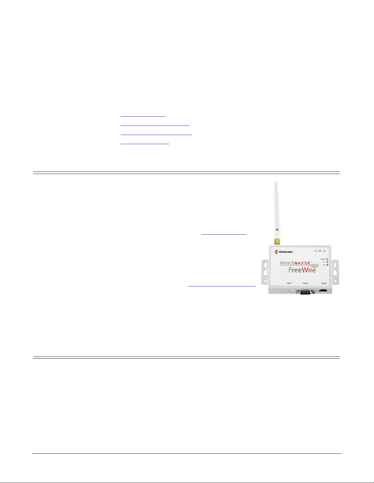
The DeviceMaster FreeWire is a high-performance, standalone device designed to
connect a wide range of serial devices (i.e., security devices, telecommunications
equipment, modems, data display devices, industrial instrumentation, etc.) to an
Ethernet network. The DeviceMaster FreeWire supports RS-232 serial interfaces
at a variety of baud rates (data transmission speeds), automatically senses both
100baseTX Fast Ethernet and 10baseT Ethernet network connections, and the
wireless capability allows connections to 802.11g wireless networks as well.
DeviceMaster FreeWire Requirements
To use the wireless DeviceMaster FreeWire, you need an 802.11g compatible
wireless network consisting of either of the following:
• An 802.11b/g wireless-enabled PC connected directly to the DeviceMaster
FreeWire (Ad-Hoc or Peer-to-Peer mode).
• An 802.11b/g wireless access point that allows wireless and wired Ethernetenabled PCs to connect to the serial server.
To configure the wireless DeviceMaster FreeWire, you will need the following
information from your wireless network administrator:
• Wireless mode used (Infrastructure or Ad-Hoc)
• The SSID (service set identifier) for your wireless network.
• The Radio Frequency Channel of the wireless network.
• If you are using TCP/IP (recommended for Windows networks) and are not
connected to a DHCP (Dynamic Host Configuration Protocol) server (for
obtaining an IP Address automatically), you will need a unique IP Address for
the DeviceMaster FreeWire (for example: 192.168.1.14). If the DeviceMaster
FreeWire is not on the same IP subnet as the PCs you are using, you will also
need a subnet mask and a router (default gateway) address.
• Wireless Security Settings (WEP keys, 802.1x settings, etc.)
Installation Overview
The DeviceMaster FreeWire installation follows these steps:
1. Install the hardware (Hardware Installation
2. Configure the DeviceMaster FreeWire using Configuration Options
to locate configuration procedures for your environment.
3. If necessary, update the firmware (Checking the Firmware Version
35).
4. Connect your serial device to the DeviceMaster FreeWire (Connecting the
Serial Device on Page 41).
DeviceMaster FreeWire Installation and User Guide: 2000412 Rev. D Product Overview - 5
on Page 7).
on Page 6
on Page
Page 6

Configuration Options
Configuration Options
After the hardware installation has been successfully completed, the
DeviceMaster FreeWire is ready for configuration. The easiest and fastest way to
configure the DeviceMaster FreeWire is to use the DeviceMaster FreeWire
Installation Wizard, which also installs the FreeWire Manager, a configuration
interface, and the port redirector.
Note: Comtrol Technical Support recommends using the FreeWire Installation
Use Configuring the DeviceMaster FreeWire
configuration procedures, such as:
• Easily configure DeviceMaster FreeWire network and wireless settings
• Check DeviceMaster FreeWire status information
• Change options such as the DeviceMaster FreeWire access protocol and time-
• Access the web page to update firmware
Basic COM port properties can be configured using the DeviceMaster FreeWire
Installation Wizard and advanced properties can be configured using the FreeWire
Manager.
Optionally, you could use one of the other DeviceMaster FreeWire configuration
and management methods.
• Embedded web server page (Page 27
• DeviceMaster FreeWire internal configuration console, which can be accessed
Wizard and FreeWire Manager for configuration. If you do not have access
to a Windows system, use one of the other methods discussed below.
on Page 13 for installation and
out values
browser (for example, Firefox or Internet Explorer), with no additional
software and on any system that supports web browser capabilities. Simply,
type the IP address into your web browser address bar to connect. The default
address is 192.168.250.250.
via a Telnet connection or directly through the DeviceMaster FreeWire serial
port (Page 31
Use the Command Console to configure Bridged Network Mode
).
) which is accessed with a standard web
.
DeviceMaster FreeWire Downloads
You can download the latest files using the CD that accompanies the
DeviceMaster FreeWire or by locating files on the Comtrol FTP Interface at:
ftp://ftp.comtrol.com/html/freewire_main.htm.
6 - Product Overview DeviceMaster FreeWire Installation and User Guide: 2000412 Rev. D
Page 7
Device Descriptions
Hardware Installation
This section discusses the following hardware related topics in addition to the
hardware installation procedure:
• Device Descriptions (below)
• LED Indicators
• Reset Button Functions
• Factory Default Settings
• Port Parameters
The DeviceMaster FreeWire includes the
components that are discussed in the following
subsections:
• Power connector – The power supply cable plugs
into this connector.
• LED status indicators (Power, 10, and 100) –
Indicate the operational states of the
DeviceMaster FreeWire. See LED Indicators
Page 9 for detailed LED status light
descriptions.
• Reset button – Pressing the Reset button for less
than five seconds prints a test page (if the
device is connected to a serial printer). Pressing
and holding the Reset button for more than five
seconds resets the DeviceMaster FreeWire to
factory default settings (Reset Button Functions
on Page 9).
• 10/100 – The RJ45 Ethernet port is used for
connecting the DeviceMaster FreeWire to an Ethernet card, hub, router, or
other wired access point for network access.
• RS232 – The DB9 serial port can be configured to connect the DeviceMaster
FreeWire to a serial device that uses the RS-232 serial interface.
on Page 9
on Page 9
on Page 10
on Page 11
on
Installing the DeviceMaster FreeWire Hardware
The DeviceMaster FreeWire can be wall mounted, set on the desktop, or mounted
using the optional DIN rail kit available from Comtrol Corporation.
1. Write down the 12-digit MAC (Media Access Code) address printed on the
label located on the bottom of the DeviceMaster FreeWire (for example: 00 C0
4E 27 00 00). You may need this number in order to configure the DeviceMaster
FreeWire.
2. Plug the DeviceMaster FreeWire power supply adapter into a suitable AC
receptacle, and then plug the power supply cable into the DeviceMaster
FreeWire. The DeviceMaster FreeWire will run through a sequence of powerup diagnostics for a few seconds.
DeviceMaster FreeWire Installation and User Guide: 2000412 Rev. D Hardware Installation - 7
Page 8

Installing the DeviceMaster FreeWire Hardware
• If the DeviceMaster FreeWire is operating properly, the LEDs will blink
momentarily and then go out, the yellow (10) and green (100) LEDs will
illuminate if the network is active, and the orange (Power) LED will
illuminate, indicating the device is receiving power.
• The unit powers up in the Normal mode, which provides for connection
from the network to the device connected to the serial port of the
DeviceMaster FreeWire.
•If the Power LED blinks continuously in a regular pattern, a problem exists.
If this is the case, try powering the unit off and then on again. If the
problem persists, refer to Troubleshooting
See LED Indicators
3. Connect the DeviceMaster FreeWire to your network through a switch or hub
using a category 5 (CAT5) Ethernet cable. The DeviceMaster FreeWire IP
address must be configured before a network connection is available.
• The DeviceMaster FreeWire is configured with a static (fixed) IP address of
192.168.250.250 (see your system administrator for assistance). In most
cases, a fixed IP address is preferred because a DHCP server may not
always assign the same IP address to the DeviceMaster FreeWire when the
DeviceMaster FreeWire is powered on.
• If you want to use DHCP, you must configure the DeviceMaster FreeWire
for DHCP during the network configuration process.
Note: If a wired connection is established to the unit, the wireless link will be
disabled. The IP address must be within a valid range, unique to your
network, and in the same subnet as your PC.
4. Go to Configuring the DeviceMaster FreeWire
FreeWire configuration procedures for Windows operating systems.
Optionally, you can go to Web Browser and Console Configuration
on Page 47.
on Page 9 for detailed information about the LEDs.
on Page 13 for DeviceMaster
on Page 27.
8 - Hardware Installation DeviceMaster FreeWire Installation and User Guide: 2000412 Rev. D
Page 9

LED Indicators
LED Indicators
The DeviceMaster FreeWire provides three multifunction LED indicators (yellow,
green, and orange) for easy monitoring.
The following table defines the function of each LED.
Function State Status
POWER
(Orange)
NETWORK
STATUS
(Yellow/Green)
ON
OFF
Blinking
Yellow OFF
Green OFF
Yellow ON
Green OFF
Yellow Blinking
Green OFF
Yellow OFF
Green ON
Yellow OFF
Green Blinking
Yellow ON
Green ON
Yellow Blinking
Green Blinking
The DeviceMaster FreeWire is receiving
power
The DeviceMaster FreeWire is not
receiving power
The DeviceMaster FreeWire power supply
is malfunctioning
No network activity
10baseT network active
10baseT network data received
100baseTX network active
100baseTX network data received
Wireless network active
Wireless network data received
Reset Button Functions
Action Result
Generates configuration data that can be viewed using a
Depress for less
than 5 seconds
Depress for more
than 5 seconds
Depress for 3
seconds during
power up
DeviceMaster FreeWire Installation and User Guide: 2000412 Rev. D Hardware Installation - 9
terminal emulator (e.g., Windows Hyper Terminal) or other
serial device that can display ASCII characters, or it will
initiate a test page if the DeviceMaster FreeWire is connected
to a serial printer.
Resets the DeviceMaster FreeWire’s configuration to factory
defaults (cold reset). The unit will automatically re-initialize
after updating the configuration memory.
Places the device into console configuration mode, which can
be used to configure the device via the DeviceMaster
FreeWire’s serial port. See Using the Command Console
on
Page 31.
Page 10

Factory Default Settings
Factory Default Settings
The DeviceMaster FreeWire is shipped with a default configuration that works
with the most common serial-to-Ethernet and wireless connections. The default
settings can be changed to suit specific installation requirements using the
FreeWire Manager, embedded web server page, or a Telnet connection to the
DeviceMaster FreeWire internal console.
The factory default settings can be easily restored at any time by performing a
cold reset (press and hold the Reset button on the device for more than five
seconds).
The following table lists the DeviceMaster FreeWire default settings.
Character bits per character 8
Flow flow control None
Parity parity None
Baud rate bits per second 115,200
Stop stop bits per character 1
Mode line mode (serial port protocol) 232
ECABLE E-Cable mode (for TCP connections) Disable
ECADDR E-Cable destination IP address (set by user)
ECONN E-Cable connection attempt time 20 seconds
ECPORT E-Cable destination IP port number 9100 (raw data)
Web browser password (not case-sensitive) access
Network
settings
Protocols DHCP, static addressing, arp, rasp, and BootP protocols
Parameter Description Settings
IP address
Subnet mask
Default Gateway
192.168.250.250
255.255.0.0
0.0.0.0
10 - Hardware Installation DeviceMaster FreeWire Installation and User Guide: 2000412 Rev. D
Page 11

Port Parameters
Port Parameters
Parameter Description Settings
CHARACTER bits per character 7, 8 (default)
FLOW flow control NONE (default), Xon/Xoff, CTS/RTS
PARITY parity
SPEED
STOP
MODE
baud rate (bits per
second)
stop bits per
character
line mode (serial port
protocol)
E-Cable mode (for
ECABLE
TCP connections
similar to serial
tunneling)
ECADDR
ECONN
ECPORT
E-Cable destination
IP address
E-Cable connection
attempt time
E-Cable destination
IP port number
NONE (default), EVEN, ODD, MARK, or
SPACE
300, 600, 1200, 2400, 3600, 4800, 7200,
9600, 14400, 19200, 38400, 57600, 76800,
115200 (default), 230400, 460800
1 (default), 2
232 (default), Disabled
Enable, Disable (default)
(Originator; master only,
(set by user)
20 seconds
9100 (raw data), 9200 (telnet) or set by
user
Note: The default IP address is 192.168.250.250.
DeviceMaster FreeWire Installation and User Guide: 2000412 Rev. D Hardware Installation - 11
Page 12

Port Parameters
This page was intentionally left blank.
12 - Hardware Installation DeviceMaster FreeWire Installation and User Guide: 2000412 Rev. D
Page 13

Configuring the DeviceMaster FreeWire
The easiest and fastest way to configure the DeviceMaster FreeWire is to use the
FreeWire Installation Wizard for Windows, which supports:
• Windows XP
• Windows Server 2003
• Windows Vista
• Windows Server 2008
• Windows 7
The FreeWire Installation Wizard also installs the FreeWire Manager and the port
redirector after setting up basic configuration settings.
The FreeWire Manager provides an alternate method to configure the network,
wireless serial settings. In addition, you can use the FreeWire Manager to:
• Check DeviceMaster FreeWire status information
• Change network and wireless settings, including access protocol
• Configure advanced serial settings
• Access the web page to update firmware
This section discusses the following topics:
• Installing the DeviceMaster FreeWire Installation Wizard
• Configuring Network and Wireless Settings
- Advanced Serial Port Configuration
- Configuring Ad Hoc Mode
Optionally, you can use the embedded web server page or Command Console for
configuration, see Web Browser and Console Configuration
on Page 25
on Page 24
on Page 24
(below)
on Page 27.
DeviceMaster FreeWire Installation and User Guide: 2000412 Rev. D Configuring the DeviceMaster FreeWire - 13
Page 14

Installing the DeviceMaster FreeWire Installation Wizard
Installing the DeviceMaster FreeWire Installation Wizard
After the hardware installation has been successfully completed, you can
configure the DeviceMaster FreeWire.
1. If you have not done so, locate the DeviceMaster FreeWire Installation Wizard
on the CD that shipped with the DeviceMaster FreeWire or use the ftp site
The DeviceMaster FreeWire Installation Wizard installs the FreeWire
Manager and port redirector.
2. Execute the FreeWire Installation Wizard .msi file and click Next.
.
3. To use the default installation path, click Next.
14 - Configuring the DeviceMaster FreeWire DeviceMaster FreeWire Installation and User Guide: 2000412 Rev. D
Page 15
Installing the DeviceMaster FreeWire Installation Wizard
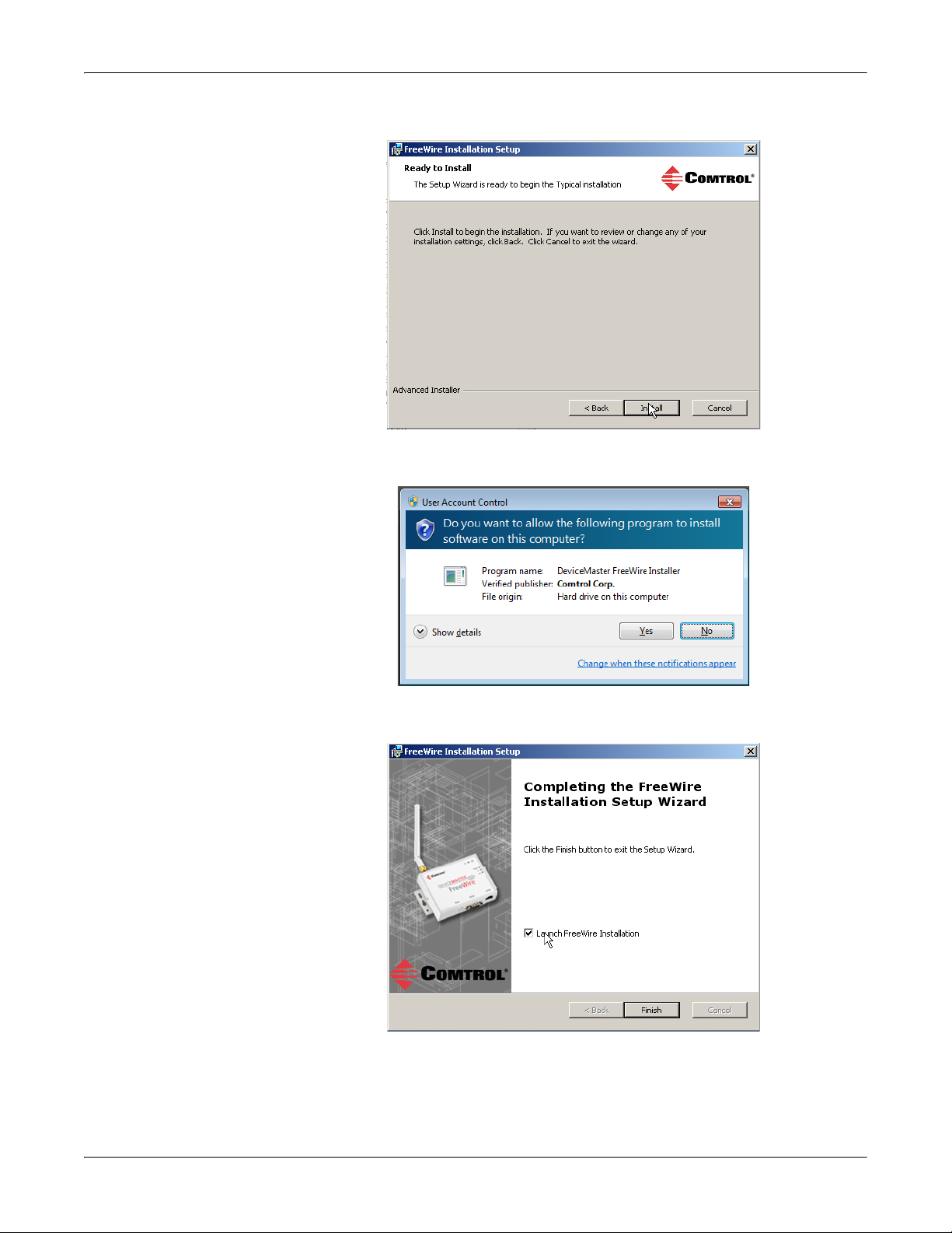
4. Click Install to continue the installation.
Depending on the operating system, you may need to click Ye s to allow the
software installation.
5. Click Launch FreeWire Installation and Finish to complete the FreeWire
Installation Setup.
DeviceMaster FreeWire Installation and User Guide: 2000412 Rev. D Configuring the DeviceMaster FreeWire - 15
Page 16
Installing the DeviceMaster FreeWire Installation Wizard
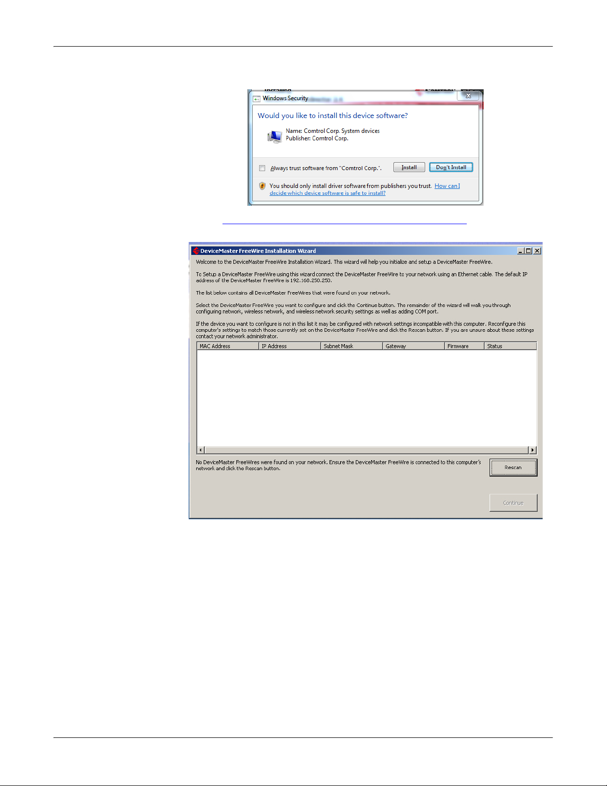
Depending on the operating system, click Install if prompted.
Go to Using the DeviceMaster FreeWire Installation Wizard
begin the DeviceMaster FreeWire configuration process.
on Page 17 to
16 - Configuring the DeviceMaster FreeWire DeviceMaster FreeWire Installation and User Guide: 2000412 Rev. D
Page 17
Using the DeviceMaster FreeWire Installation Wizard
Using the DeviceMaster FreeWire Installation Wizard
The DeviceMaster FreeWire default address is 192.168.250.250. It may be
necessary to change the IP address on your host system temporarily to program
the IP address into the DeviceMaster FreeWire. For example: The network
segment must be 192.168.250.x to program the DeviceMaster FreeWire IP address
for your network.
Use this procedure to configure the DeviceMaster FreeWire.
1. If you have not so, install the DeviceMaster FreeWire Installation Setup (Page
14).
2. If necessary, start the DeviceMaster FreeWire Installation Wizard using the
desktop shortcut or Start/Programs/Comtrol/FreeWire/FreeWire Installation
Wizard.
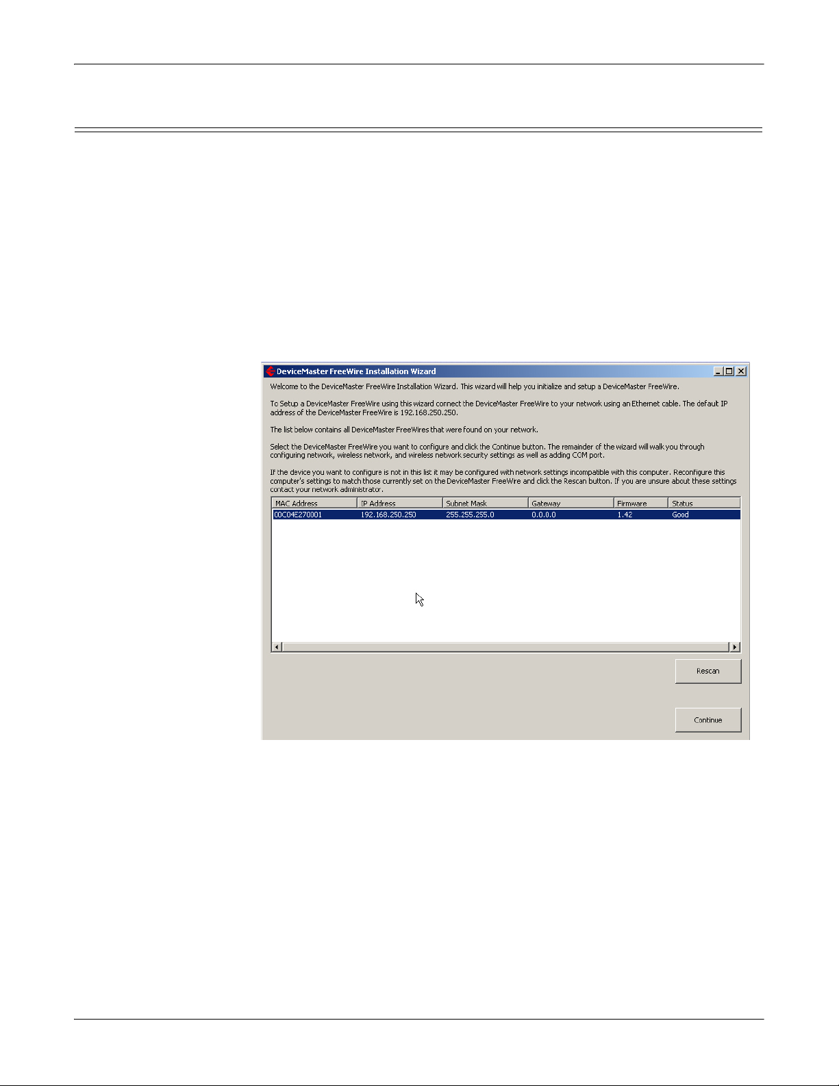
3. Highlight the DeviceMaster FreeWire that you want to configure and click
Continue.
If the DeviceMaster FreeWire that you want to configure does not appear in
the list, click Rescan.
Note: If you have not done so, you must change the IP address on your host to
192.168.250.x so that the DeviceMaster FreeWire Installation Wizard
can communicate with the DeviceMaster FreeWire.
DeviceMaster FreeWire Installation and User Guide: 2000412 Rev. D Configuring the DeviceMaster FreeWire - 17
Page 18

Using the DeviceMaster FreeWire Installation Wizard
4. Configure the network settings for your environment.
a. After entering the network settings, you can click Run Test to verify that
DeviceMaster FreeWire has been programmed with valid network settings
or optionally, click Next and go to Step 5.
b. Click Continue.
c. If you programmed the DeviceMaster FreeWire for your network
addressing scheme, you can change the IP address on your host machine
back to the appropriate network settings while this message is displaying.
d. If the DeviceMaster FreeWire network settings are valid, a green check
mark appears next to the Run Test button.
e. Click Next to continue the configuration process.
18 - Configuring the DeviceMaster FreeWire DeviceMaster FreeWire Installation and User Guide: 2000412 Rev. D
Page 19

Using the DeviceMaster FreeWire Installation Wizard
5. Enter the SSID and channel for your wireless network and then click Next.
6. Select the appropriate Authentication (WPA-PSK, WEP, or Open) for your
wireless network and complete the fields that appear for that selection.
DeviceMaster FreeWire Installation and User Guide: 2000412 Rev. D Configuring the DeviceMaster FreeWire - 19
Page 20

Using the DeviceMaster FreeWire Installation Wizard
a. To test the wireless network and security settings, click Run Test or
optionally, click Next and go to Step 7.
b. Click Continue.
c. Click Continue.
d. Disconnect the Ethernet cable and then click Continue.
20 - Configuring the DeviceMaster FreeWire DeviceMaster FreeWire Installation and User Guide: 2000412 Rev. D
Page 21

Using the DeviceMaster FreeWire Installation Wizard
e. If the DeviceMaster FreeWire wireless settings are valid, a green check
mark appears next to the Run Test button.
f. Click Next to continue the configuration process.
DeviceMaster FreeWire Installation and User Guide: 2000412 Rev. D Configuring the DeviceMaster FreeWire - 21
Page 22

Using the DeviceMaster FreeWire Installation Wizard
7. Select an available COM port number.
a. To test the COM port, click Run Test or optionally, click Next and go to Step
8.
b. Click Continue.
c. Insert the loopback plug that was shipped with the into the serial port and
click Continue.
22 - Configuring the DeviceMaster FreeWire DeviceMaster FreeWire Installation and User Guide: 2000412 Rev. D
Page 23

Using the DeviceMaster FreeWire Installation Wizard
d. If the COM selection is valid, a green check mark appears next to the Run
Te st button.
e. Click Next.
8. If you have not do so, you may want to click Run Test to verify that valid
configuration setting have been selected. If you have tested each configuration
step, it is not necessary to retest the DeviceMaster FreeWire.
9. Click Finish to complete the first phase of the configuration process.
10. In some cases, you may need to perform more configuration procedures:
• To configure serial port characteristics, go to Advanced Serial Port
Configuration on Page 24
• To configure Ad Hoc wireless settings, go to Configuring Ad Hoc Mode
on
Page 25
DeviceMaster FreeWire Installation and User Guide: 2000412 Rev. D Configuring the DeviceMaster FreeWire - 23
Page 24

Configuring Network and Wireless Settings
Configuring Network and Wireless Settings
After initial DeviceMaster FreeWire configuration using the Installation Wizard,
you can use the Installation Wizard to change network or wireless settings.
Optionally, you can use the FreeWire Manager to change your network or wireless
settings. In addition, you can use the FreeWire Manager if you need to perform
advanced configuration such as:
• Serial port
- Protocol (raw data or Telnet)
- Settings, for example: baud rate, data bits, parity bit, stop bits, and flow
control
• Wireless (Ad hoc or infrastructure)
•Network
Advanced Serial Port Configuration
Use the following procedure if you need to configure advanced serial port settings
for the DeviceMaster FreeWire.
1. Start the FreeWire Manager (desktop shortcut or Start/Programs/Comtrol/
FreeWire/FreeWire Manager).
2. Highlight the DeviceMaster FreeWire that you want to configure and click the
Serial Port tab.
3. Set the options that reflect your serial device’s properties.
4. Click Apply to Device.
5. If you have completed all settings changes, click Exit.
24 - Configuring the DeviceMaster FreeWire DeviceMaster FreeWire Installation and User Guide: 2000412 Rev. D
Page 25

Configuring Ad Hoc Mode
Configuring Ad Hoc
Mode
Use the following procedure if you need to configure the DeviceMaster FreeWire
for Ad hoc mode.
1. Start the FreeWire Manager (desktop shortcut or Start/Programs/Comtrol/
FreeWire/FreeWire Manager).
2. Highlight the DeviceMaster FreeWire that you want to configure and click the
Wireless tab.
3. Click Ad hoc.
4. Click the appropriate Security settings for your environment.
5. Click Apply To Device.
6. If you have completed all settings changes, click Exit.
7. If you do not have any other DeviceMaster FreeWire units to configure, close
the FreeWire Manager.
Refer to Connecting the Serial Device
on Page 41 for serial port pin-out
information.
DeviceMaster FreeWire Installation and User Guide: 2000412 Rev. D Configuring the DeviceMaster FreeWire - 25
Page 26

Configuring Ad Hoc Mode
26 - Configuring the DeviceMaster FreeWire DeviceMaster FreeWire Installation and User Guide: 2000412 Rev. D
Page 27

Web Browser and Console Configuration
After the hardware installation has been successfully completed, the
DeviceMaster FreeWire is ready for configuration.
Most installations can use the FreeWire Installation Wizard for Windows, which
also installs the FreeWire Manager, a configuration interface. The FreeWire
Installation Wizard and FreeWire Manager can be used for typical installations. If
you do not have a Windows system, you can use the embedded web server page.
In addition, there are configuration options that may need to be configured for
your environment using the web browser interface or optionally, the Command
Console.
This section also discusses how to operate DeviceMaster FreeWire in Bridging
Network Mode. You may want to review these subsections before using Bridging
Network Mode:
• Limitations of Bridging Network Mode
• Behavior in Ad-Hoc Mode
• Behavior in Infrastructure Mode
Configuration Options
on Page 33
on Page 33
on Page 33
The DeviceMaster FreeWire also provides additional configuration and
management methods.
• Embedded web server page (Page 27
browser (for example, Firefox or Internet Explorer), with no additional
software and on any system that supports web browser capabilities. Simply,
type the IP address into your web browser address bar to connect.
• DeviceMaster FreeWire internal configuration console, which can be accessed
using a Telnet connection or directly through the DeviceMaster FreeWire
serial port (Page 31
connection. The Command Console is a command-line-oriented console, which
provides some advanced features not available through the embedded web
server page or the FreeWire Manager.
Using the Web Browser Interface
Optionally, you can configure the DeviceMaster FreeWire using a standard web
browser to access the DeviceMaster FreeWire embedded web server pages, which
contain the DeviceMaster FreeWire configuration options. No additional software
is required.
Note: To configure the DeviceMaster FreeWire, the IP address must also be valid
for the network to which it is attached. The network segment must be
192.168.250.x to communicate to the DeviceMaster FreeWire default IP
address of 192.168.250.250.
1. Verify that your PC is connected and has access to the network.
2. If you have not done so, connect an available Ethernet cable from your
network hub to the DeviceMaster FreeWire and verify that the DeviceMaster
FreeWire is powered on.
) which is accessed with a standard web
) using a DB9 RS-232 null-modem cable for serial
DeviceMaster FreeWire Installation and User Guide: 2000412 Rev. D Web Browser and Console Configuration - 27
Page 28

Using the Web Browser Interface
3. Enter the DeviceMaster FreeWire IP address in your web browser. The Server
4. Click the Login menu selection (left), enter the password (default is access),
To operate on an 802.11b/g network, you must set up the same configuration
as the wireless network you want the DeviceMaster FreeWire to communicate
on. All nodes of a wireless network need to have the same settings in order to
communicate with each other.
• Wireless mode (ad-hoc or infrastructure)
•SSID channel
•Data rate
• Security settings (WEP keys, 802.1x settings, etc.)
Info screen displays.
and then click Submit.
5. You should check the firmware version (Page 35
) and if necessary, update the
firmware before configuring the DeviceMaster FreeWire using the web page.
Note: Use the Help system if you need information about any of the settings.
28 - Web Browser and Console Configuration DeviceMaster FreeWire Installation and User Guide: 2000412 Rev. D
Page 29

Using the Web Browser Interface
6. Use the following web pages to configure the settings of the DeviceMaster
FreeWire. The menu selections are displayed on the left side of the screen, and
the individual settings are located at the top of the screen. At a minimum, you
need to configure the following pages:
• I/O Port - if you are using the serial port in socket mode.
• TCP/IP- to configure the DeviceMaster FreeWire IP address for your
network.
DeviceMaster FreeWire Installation and User Guide: 2000412 Rev. D Web Browser and Console Configuration - 29
Page 30

Using the Web Browser Interface
• Wireless - to
configure the
wireless settings
that match your
network.
• Admin - you may
want to configure network
access password and an
update password, which
prevents unauthorized
configuration changes.
7. To confirm wireless
operation:
a. Close the web browser
and disconnect the
Ethernet cable.
a. Re-open the web browser,
enter the IP address, and
verify that Server Info
web page loads.
Note: It takes
approximately 7
seconds before the
connection is
operational.
If the web page does not
load, see Troubleshooting
on Page 47.
8. Refer to Connecting the Serial Device
information.
on Page 41 for serial port pinout
30 - Web Browser and Console Configuration DeviceMaster FreeWire Installation and User Guide: 2000412 Rev. D
Page 31

Using the Command Console
Using the Command Console
You can use a telnet or serial connection to configure the DeviceMaster FreeWire
using the Command Console.
This subsection also discusses how to operate DeviceMaster FreeWire in Bridging
Network Mode using the Command Console.
Telnet Connection Use this procedure to access the Command Console through telnet.
Note: To configure the DeviceMaster FreeWire, the IP address must also be valid
1. Verify that the DeviceMaster FreeWire is connected via an Ethernet cable to
2. From the Windows Start menu, click Run, and then type the following
3. After a connection is established, press Return or Enter to get the # prompt.
4. Enter the password, access (it will not “echo” on your screen), and type
5. After configuring the DeviceMaster FreeWire, confirm wireless operation:
Refer to Connecting the Serial Device
and Verifying the Installation
for the network to which it is attached. The network segment must be
192.168.250.x to communicate to the DeviceMaster FreeWire default IP
address of 192.168.250.250.
the host PC.
command (where x.x.x.x. is the IP address of the DeviceMaster FreeWire). The
system will use the default port 23.
telnet X.X.X.X
anything in response to the Enter Username> prompt.
When the Local> prompt appears, you are ready to enter commands.
For a list of commands, type help at the command prompt.
a. Close the Command Console, and disconnect the Ethernet cable.
b. Re-open a telnet session, enter the IP address, and verify that a
DeviceMaster FreeWire telnet session opens.
Note: It takes approximately 7 seconds before the connection is
operational.
If the telnet session does not start, see Troubleshooting
on Page 47.
on Page 41 for serial port pinout information
on Page 45 to complete the installation.
Serial Connection The Command Console can be accessed via a direct connection to the
DeviceMaster FreeWire serial port using a COM port emulator and a null-modem
serial cable.
1. Attach one end of a null-modem serial cable to the DB9 serial port of the
DeviceMaster FreeWire, and the other end of the cable to the COM port on
your PC.
2. Start a terminal emulation program (e.g., Windows Hyper Terminal), making
sure you are connecting with the relevant COM port.
Note: You can use Test Terminal (WCOM2), which is available on the CD.
You can also download the latest version from the ftp site
.
3. Use the following settings for the connection:
• Bits Per Second: 115200
•Data Bits: 8
• Parity: None
•Stop Bits: 1
• Flow Control: None
DeviceMaster FreeWire Installation and User Guide: 2000412 Rev. D Web Browser and Console Configuration - 31
Page 32

Operating in Bridged Network Mode
4. After opening a serial port with the appropriate settings, type the following
characters:
After typing those characters, the following prompt appears:
For a list of commands, type help at the command prompt.
5. After configuring the DeviceMaster FreeWire, confirm wireless operation:
a. Close the Command Console, and disconnect the Ethernet cable.
b. Re-open a telnet session, enter the IP address, and verify that a
Refer to Connecting the Serial Device
and Verifying the Installation
#!DM
Local>
DeviceMaster FreeWire telnet session opens.
Note: It takes approximately 7 seconds before the connection is
operational.
If the telnet session does not start, see Troubleshooting
on Page 47.
on Page 41 for serial port pinout information
on Page 45 to complete the installation.
Operating in
Bridged Network
Mode
The DeviceMaster FreeWire is capable of operating in a Bridged Networking
Mode. Under normal operations the DeviceMaster FreeWire is able to
communicate through the Ethernet or wireless interface but not both at the same
time. Using Bridging Network Mode, a single device attached to the Ethernet port
can communicate with a wireless network or device.
Configuration Placing the DeviceMaster FreeWire in Bridging Network Mode can only be done
through the Command Console. Once placed in Bridging Network Mode, telnet
and the web interface can only be accessed via the wireless interface. Since
networking settings change after enabling Bridging Network Mode, this
subsection explains how to enable this feature through the serial port, which is not
dependent on the network setup.
1. To access the Command Console, use the appropriate procedure:
• Telnet Connection
• Serial Connection
on Page 31, Steps 1 through 4.
on Page 31, Steps 1 through 4.
2. At the Local> prompt, enter the following three commands to enable Bridging
Network Mode:
set nw bridge enable
init
exit
The DeviceMaster FreeWire reboots, after which it will be in Bridging Network
Mode. The behavior of the DeviceMaster FreeWire in this mode is dependent on
whether or not the wireless interface is in infrastructure or ad-hoc mode.
Disabling Bridging Network Mode
To disable Bridging Network Mode, use the following procedure:
1. To access the Command Console, use the appropriate procedure:
• Telnet Connection
• Serial Connection
on Page 31, Steps 1 through 4.
on Page 31, Steps 1 through 4.
2. At the Local> prompt, enter the following commands to disable Bridging
Network Mode:
set nw bridge disable
init
exit
After the DeviceMaster FreeWire reboots, it is in its standard operating mode.
32 - Web Browser and Console Configuration DeviceMaster FreeWire Installation and User Guide: 2000412 Rev. D
Page 33

Limitations of Bridging Network Mode
Limitations of
Bridging Network
Mode
Behavior in Ad-Hoc Mode
Behavior in Infrastructure Mode
Bridging Network Mode on the DeviceMaster FreeWire is designed so that it
enables a single Ethernet device to become a wireless device. The DeviceMaster
FreeWire is unable to act as a typical wireless access point, which allows multiple
attached Ethernet devices to communicate with the wireless interface.
The DeviceMaster FreeWire works in a one-to-one mode. For example if you
connect a network enabled printer to the DeviceMaster FreeWire then wireless
devices can communicate with the printer.
If you attached the DeviceMaster FreeWire to a managed switch then a wireless
device is able to communicate with and manage the switch. Wirelessly connected
devices are not able to communicate with any device attached to the switch. If you
attached the DeviceMaster FreeWire to an unmanaged switch, you can
communicate with the first detected Ethernet device connected to that switch.
None of the other devices attached to the Ethernet switch are visible to the
DeviceMaster FreeWire’s wireless interface.
Thus the DeviceMaster FreeWire Bridging Network Mode can only be used to
attach one Ethernet device to a wireless network or device.
Ad-hoc mode allows a wireless device to connect to the DeviceMaster FreeWire as
though it were an access point. Use this mode when you want to directly connect
the attached Ethernet device to a computer via the wireless interface.
For example, if you want to connect a network enabled printer directly to a
computer via the wireless interface you would use ad-hoc mode.
Infrastructure mode allows the DeviceMaster FreeWire to connect to a wireless
access point. Use this mode when you want to connect an attached Ethernet device
to a wireless network. This mode differs from ad-hoc mode in that it allows
multiple devices to communicate with the attached Ethernet device via the
wireless interface.
For example, if you want to attach an Ethernet printer to your wireless network so
it can be accessed by multiple computers you would use infrastructure mode.
DeviceMaster FreeWire Installation and User Guide: 2000412 Rev. D Web Browser and Console Configuration - 33
Page 34

Behavior in Infrastructure Mode
34 - Web Browser and Console Configuration DeviceMaster FreeWire Installation and User Guide: 2000412 Rev. D
Page 35

DeviceMaster FreeWire Firmware
After the hardware installation has been successfully completed, you should check
to see if the DeviceMaster FreeWire is loaded the latest firmware.
Checking the Firmware Version
There are several ways to check the firmware version:
• DeviceMaster FreeWire Installation Wizard
• FreeWire Manager
• Web page
DeviceMaster FreeWire Installation Wizard
Use the following procedure to check the firmware version on the DeviceMaster
FreeWire after hardware installation.
1. If necessary, start the DeviceMaster FreeWire Installation Wizard using the
desktop shortcut or Start/Programs/Comtrol/FreeWire/FreeWire Installation
Wizard.
The firmware version is displayed on the right side of the DeviceMaster
FreeWire information, next to the Status.
2. Check the ftp site for a later version at ftp://ftp.comtrol.com/html/default.htm
3. If necessary, go to Uploading the Latest Firmware
DeviceMaster FreeWire Installation and User Guide: 2000412 Rev. D DeviceMaster FreeWire Firmware - 35
on Page 38.
.
Page 36

FreeWire Manager
FreeWire Manager You can use the following procedure to check the firmware version using the
FreeWire Manager.
1. Start the FreeWire Manager (desktop shortcut or Start/Programs/Comtrol/
FreeWire/FreeWire Manager).
The firmware version is displayed in the center of the DeviceMaster FreeWire
information.
2. Check the ftp site for a later version at ftp://ftp.comtrol.com/html/default.htm
3. If necessary, go to Uploading the Latest Firmware
on Page 38.
.
36 - DeviceMaster FreeWire Firmware DeviceMaster FreeWire Installation and User Guide: 2000412 Rev. D
Page 37

Web Page
Note: This example displays firmware version 1.35b.
Web Page You can use the following procedure to check the firmware version using the web
page.
Note: To communicate with the DeviceMaster FreeWire, the IP address must also
be valid for the network to which it is attached. The network segment must
be 192.168.250.x to communicate to the DeviceMaster FreeWire default IP
address of 192.168.250.250.
1. Enter the DeviceMaster FreeWire IP address in your web browser. The Server
Info screen displays.
2. Check the ftp site for a later version at ftp://ftp.comtrol.com/html/default.htm
3. If necessary, download the latest firmware and go to Uploading the Latest
Firmware on Page 38 to load the firmware into the DeviceMaster FreeWire.
.
DeviceMaster FreeWire Installation and User Guide: 2000412 Rev. D DeviceMaster FreeWire Firmware - 37
Page 38

Uploading the Latest Firmware
Uploading the Latest Firmware
Use the following procedure to upload the latest firmware into the DeviceMaster
FreeWire using the FreeWire Manager.
1. Start the FreeWire Manager (desktop shortcut or Start/Programs/Comtrol/
FreeWire/FreeWire Manager).
2. Highlight the DeviceMaster FreeWire that requires a firmware update.
3. Click Upload Firmware.
4. Enter the password (default is access), and then click Submit.
38 - DeviceMaster FreeWire Firmware DeviceMaster FreeWire Installation and User Guide: 2000412 Rev. D
Page 39

Uploading the Latest Firmware
Note: Use the Help system if you need information about any of the settings.
5. Click Continue.
6. Browse to the location you downloaded the firmware, and click Submit.
DeviceMaster FreeWire Installation and User Guide: 2000412 Rev. D DeviceMaster FreeWire Firmware - 39
Page 40

Uploading the Latest Firmware
40 - DeviceMaster FreeWire Firmware DeviceMaster FreeWire Installation and User Guide: 2000412 Rev. D
Page 41

Serial Port Signals
Pin 1
Pin 6
DB9 Male
RS-232
RI
CTS
RTS
DSR
GND
DTR
TxD
RxD
CD
Pin 1
Pin 5
Pin 6
Pin 9
Connecting the Serial Device
Connect the DeviceMaster FreeWire to your serial device using a standard RS-232
DB9 serial cable. You can build your own null-modem or straight-through DB9
serial cables using the following subsections.
The following table provide serial port pinouts for the DeviceMaster FreeWire.
DB9 Connector Pinouts
Pin RS-232
1DCD
2RxD
3TxD
4DTR
5GND
6DSR
7RTS
8CTS
RI (Ring) or +5 VDC
9
power input (selectable
via 3-pin jumper)
DB9 Loopback Plugs
Loopback connectors are DB9 female serial port plugs, with pins wired together as
shown, that are used in conjunction with application software (Test Terminal) to
test serial ports. The DeviceMaster FreeWire is shipped with a a single loopback
plug (RS-232).
Note: You can use Test Terminal to test the serial ports. You can use the Support
page on the CD shipped with the DeviceMaster FreeWire.
Wire the following pins together to build additional plugs or
replace a missing RS-232 loopback plug:
• Pins 1 to 4 to 6
•Pins 2 to 3
• Pins 7 to 8 to 9
DeviceMaster FreeWire Installation and User Guide: 2000412 Rev. D Connecting the Serial Device - 41
Page 42

DB9 Null-Modem Cables
DeviceMaster
TxD
RxD
RTS
CTS
DSR
GND
DCD
DTR
Signal
RxD
TxD
CTS
RTS
DTR
GND
DCD
DSR
Signal
DB9
2
3
8
7
4
5
1
6
Pins
DB25
3
2
4
7
8
6
Pins
20
5
Femal e
DB9
3
2
7
8
6
5
1
4
Pins
RJ45
5
4
1
3
6
7
Pins
2
8
DeviceMaster
DB9
1
2
3
4
5
8
6
7
Pins
DCD
RxD
TxD
DTR
GND
CTS
DSR
RTS
Signal
DB9
1
2
3
4
5
8
6
7
Pins
DCD
RxD
TxD
DTR
GND
CTS
DSR
RTS
Signal
Fem ale
RI 9
9RI
RJ45
6
5
4
2
3
8
7
1
Pins
N/A
DB25
8
3
2
20
7
5
6
4
Pins
22
DB9 Null-Modem Cables
Use the following figure if you need to build an RS-232 null-modem cable. A nullmodem cable is required for connecting DTE devices.
Note: You may want to purchase or build a straight-through cable and purchase a
null-modem adapter. For example, a null-modem cable can be used to
connect COM2 of one PC to COM2 of another PC.
DB9 Straight-Through Cables
Use the following figure if you need to build an RS-232 straight-through cable.
Straight-through cables are used to connect modems and other DCE devices. For
example, a straight-through cable can be used to connect COM2 of one PC to
COM2 to a modem.
42 - Connecting the Serial Device DeviceMaster FreeWire Installation and User Guide: 2000412 Rev. D
Page 43

TCP Port Connections
The DeviceMaster FreeWire supports port connections over TCP/IP using raw
TCP ports only. The TCP ports are allocated as follows.
TCP Port Connections
Port Destination Device
3001 RS-232
9100 RS-232
9200 RFC 2217
You should set the port to port
forwarding in routers and firewalls.
DeviceMaster FreeWire Installation and User Guide: 2000412 Rev. D Connecting the Serial Device - 43
Page 44

TCP Port Connections
This page was intentionally left blank.
44 - Connecting the Serial Device DeviceMaster FreeWire Installation and User Guide: 2000412 Rev. D
Page 45

Verifying the Installation
There are several ways to verify that the serial port is functioning. This section
discusses how to test a serial device able to display ASCII characters.
Refer to the DeviceMaster FreeWire Software and Documentation CD for
procedures of how to use Test Terminal and the loopback plug to verify that the
serial port is functioning.
Use the following procedure to verify that the DeviceMaster FreeWire and the
serial device are working correctly.
1. Verify that both the DeviceMaster FreeWire and the connected serial device
are powered on and ready, and that a serial cable is properly connected
between the DeviceMaster FreeWire and serial device (i.e., transmit signal
output from the DeviceMaster FreeWire going to the receive signal input on
the serial device, ground leads connected together, etc.).
Note: Before attempting to use the DeviceMaster FreeWire, you must verify the
connection between the DeviceMaster FreeWire and the connected serial
device. If this connection is not working, you will not be able to send
and/or receive data from the connected serial device.
2. Verify that the DeviceMaster FreeWire port settings (i.e., baud rate, flow
control, character bit size, parity, etc.) exactly match the settings of the
connected serial device port.
3. If the serial device connected to the DeviceMaster FreeWire is able to display
or print ASCII characters (such as a terminal emulator or serial printer), then
communication between the devices can be verified by pressing the Reset
button on the DeviceMaster FreeWire for about one second (but less than five
seconds), which initiates the output of configuration data from the
DeviceMaster FreeWire to the connected serial device.
• If communication has been successfully established between the two
devices, the serial device should be able to display or print the
DeviceMaster FreeWire’s configuration data.
• If no data is displayed or printed, verify that both devices are powered ON,
are properly connected using a suitable serial cable, and are using
compatible serial port parameters. The two most common serial
communication problems are due to the either the cabling and/or
mismatched serial port parameters.
Note: If the DeviceMaster FreeWire is connected to a serial device that cannot
display or print ASCII characters, then it is recommended that another
serial device capable of displaying or printing ASCII characters be
temporarily connected to the DeviceMaster FreeWire in order to verify the
serial connection. After successful communication is verified using the
temporary serial device, reconnect the original serial device, making sure
that the original serial device is configured with serial port parameters that
match the tested connection.
If you are having installation problems, see Troubleshooting
Software and Documentation CD for assistance.
on Page 47 or the
DeviceMaster FreeWire Installation and User Guide: 2000412 Rev. D Verifying the Installation - 45
Page 46

46 - Verifying the Installation DeviceMaster FreeWire Installation and User Guide: 2000412 Rev. D
This page was intentionally left blank.
Page 47

Troubleshooting
This section describes procedures for troubleshooting problems you may encounter
with the DeviceMaster FreeWire, and is divided into the following sections:
• Troubleshooting Installation Problems
• Troubleshooting Network Configuration Problems
• Troubleshooting Windows Problems
• Troubleshooting Wireless Configuration Problems
If your problem is not resolved using the troubleshooting sections, you can use
Where to Get Help
Troubleshooting Installation Problems
If you cannot access the connected serial device via the DeviceMaster FreeWire,
first check the network connection and cabling.
• Check the physical cabling to ensure all cables are plugged in (Ethernet and
DB9 serial cable).
• If the appropriate LEDs (LED Indicators
there is probably a bad 10baseT or 100baseTX cable, or the hub port is bad. If
possible, try a different cable and hub port, or try connecting a different device
to the cable.
• Verify that you using the correct values for both IP Address and Port Number.
A common mistake is to assume the TCP port number is the “device number”
on the server.
• If you are using a hub, verify that the hub port is operating correctly by trying
the DeviceMaster FreeWire on a different port.
on Page 49 for additional help.
on Page 47
on Page 48
on Page 48
on Page 9) are not illuminated, then
Troubleshooting Network Configuration Problems
The following information may help you diagnose network configuration problems.
• If you are using TCP/IP, make sure that your PC and the DeviceMaster
FreeWire are on the same IP segment or can reach each other with a PING
command from the host. The IP address you assign to the DeviceMaster
FreeWire must be on the same logical network as your host PCs (e.g., if your
PC has an IP address of 192.189.207.3, the DeviceMaster FreeWire should have
an IP address of 192.189.207.x, where x is an integer between 1 and 254), or you
must properly configure your router address to work with the DeviceMaster
FreeWire.
• If your DeviceMaster FreeWire is set to Auto or DHCP for obtaining an IP
address, it is possible that the DeviceMaster FreeWire IP address can change.
Either configure your DHCP server to give the DeviceMaster FreeWire a
permanent lease, or configure the DeviceMaster FreeWire to be on a STATIC
IP address outside the scope of the DHCP addresses.
DeviceMaster FreeWire Installation and User Guide: 2000412 Rev. D Troubleshooting - 47
Page 48

Troubleshooting Windows Problems
• Check to see if you have mismatched or duplicate IP addresses. Verify that the
IP address is correctly loaded into the DeviceMaster FreeWire (via the
displayed or printed configuration information or through the remote console),
and make sure that no other nodes on the network have this address
(duplicate addresses are the biggest cause of TCP/IP connectivity problems). If
the IP address is not correct, then check whether the loading procedure was
properly executed.
• Verify that the host PC and the DeviceMaster FreeWire are either on the same
subnet (for example, if the DeviceMaster FreeWire has a subnet mask of
255.255.255.0, the host must have the same subnet mask) or that the router is
properly configured to pass data between the two devices.
• If the wrong IP address is loaded, check your network for file servers that have
DHCP, BOOTP, or rarp enabled, and make sure that these file servers are not
set up to load IP addresses into the DeviceMaster FreeWire.
Troubleshooting Windows Problems
• If you are having trouble accessing the connected serial device through
Windows, ensure you can ping the DeviceMaster FreeWire using the DOS
command PING ipaddress, where ipaddress is the IP address of the
DeviceMaster FreeWire. If you cannot ping the DeviceMaster FreeWire, you
will not be able to access the serial device.
• If the DeviceMaster FreeWire COM port redirector reports an error, verify
that the correct serial/IP COM port is being used when the application runs.
Verify that your application’s COM port settings have been changed to use the
serial/IP COM ports.
Troubleshooting Wireless Configuration Problems
• Verify that your PC’s wireless adapter and/or access point is configured
properly – note the settings, paying special attention to the wireless mode,
SSID or network name, WEP or security, and IP address settings so you can
configure your DeviceMaster FreeWire to the same wireless settings.
• Make sure you have a good wireless signal from your PC and from the
DeviceMaster FreeWire, that the DeviceMaster FreeWire is within range (90
meters or 300 feet), and that it is away from metal objects and other devices
that generate radio signals (like Bluetooth devices, cordless phones, and
microwave ovens).
• Make sure your PC is set to infrastructure mode if you are connecting through
an access point, or ad-hoc (802.11) if you are connecting to the DeviceMaster
FreeWire without an access point. See the documentation for your wireless
adapter for details.
• If you want to use WEP encryption or password protection for your wireless
network, and your wireless adapter or access point normally uses a password
or passphrase instead of WEP, it should allow you to enter 0x followed by a 10digit key (for 40-bit or 64-bit WEP) or 26-digit key (for 128-bit WEP) in
hexadecimal format (0-9 or A-F).
• If you are experiencing slow performance or are having intermittent problems
connecting, try changing the RF channel of your wireless network. The RF
channel can be changed Using the Web Browser Interface
DeviceMaster FreeWire. See your wireless adapter and/or access point
documentation for more information. When changing the RF channel, it is
recommended that you select a channel that is at least three channels lower or
higher than any other wireless networks within range.
on Page 27 for the
48 - Troubleshooting DeviceMaster FreeWire Installation and User Guide: 2000412 Rev. D
Page 49

Where to Get Help
Where to Get Help
Comtrol Corporation offers several customer support options to assist you in the
event you experience difficulties with the DeviceMaster FreeWire, including
telephone support, repair services, and warranty.
Your first point of contact for technical support is the Distributor or Dealer from
whom you bought your product. They are familiar with your needs, and will
generally be able to provide you with the fastest and most comprehensive support.
If your Distributor or Dealer is unable to answer your questions or is for some
reason not available, then contact Comtrol Corporation.
Before contacting Technical Support, please refer to the troubleshooting
suggestions or the web site in this manual to isolate any problems, and be sure to
write down any error messages. Also, make sure that you have the serial number
of the product (located on the product label on the back of the DeviceMaster
FreeWire).
Comtrol Contact Information
Downloads ftp://ftp.comtrol.com/html/default.htm
Web s ite http://www.comtrol.com
Forum http://formum.comtrol.com
Phone (763) 494-4100
DeviceMaster FreeWire Installation and User Guide: 2000412 Rev. D Troubleshooting - 49
Page 50

Where to Get Help
This page was intentionally left blank.
50 - Troubleshooting DeviceMaster FreeWire Installation and User Guide: 2000412 Rev. D
Page 51

Safety and Regulatory Notices
This section provides the following:
• Information for United States Users
• Declaration of Conformity (FCC) on Page 52
• Information for Canadian Users (IC notice)
• Information for European Users
Information for United States Users
This equipment has been tested and found to comply within the limits for a Class
B digital device pursuant to Part 15 of the FCC Rules. These limits are designed to
provide reasonable protection against harmful interference in a residential
installation. This equipment generates, uses, and can radiate radio frequency
energy and, if not installed and used in accordance with the instructions, may
cause harmful interference to radio communications. However, there is no
guarantee that interference will not occur in a particular installation. If this
equipment does cause harmful interference to radio and television reception,
which can be determined by turning the equipment off and on, the user is
encouraged to try to correct the interference by one or more of the following
measures:
• Reorient or relocate the receiving antenna.
• Increase the separation between the equipment and receiver, Connect the
equipment into an outlet on a circuit different from that to which the receiver
is connected.
• Consult the dealer or an experienced radio/TV technician for help.
The user is cautioned that changes and modifications made to the equipment
without the approval of manufacturer could void the user’s authority to operate
this equipment.
Operation is subject to the following two conditions: (1) This device may not cause
harmful interference, and (2) this device must accept any interference received,
including interference that may cause undesired operation.
The radiated output power of the print server is far below the FCC radio frequency
exposure limits. Nevertheless, print server shall be used in such a manner that
the potential for human contact during normal operation is minimized.
To satisfy RF exposure requirements, this device and its antenna(s) must operate
with a separation distance of at least 20 centimeters from all persons and must
not be co-located or operating in conjunction with any other antenna or
transmitter. End-users must be provided with specific operating instructions for
satisfying RF exposure compliance.
on Page 52
on Page 52
DeviceMaster FreeWire Installation and User Guide: 2000412 Rev. D Safety and Regulatory Notices - 51
Page 52

Declaration of Conformity (FCC)
Declaration of Conformity (FCC)
According to 47CFR, Part 2 and 15 for Class B Personal Computers and
Peripherals; and/or CPU Boards and Power Supplies used with Class B Personal
Computers:
Comtrol Corporation
6655 Wedgwood Road
Maple Grove, MN 55311
Declare under sole responsibility that the product identified herein, complies with
47CFR Part 2 and 15 of the FCC rules as a Class B digital device FOR HOME OR
OFFICE USE. Each product marketed, is identical to the representative unit
tested and found to be compliant with the standards. Records maintained continue
to reflect the equipment being produced can be expected to be within the variation
accepted, due to quantity production and testing on a statistical basis as required
by 47CFR §2.909. Operation is subject to the following two conditions: (1) this
device may not cause harmful interference, and (2) this device must accept any
interference received, including interference that may cause undesired operation.
Information for Canadian Users (IC notice)
The term “IC” before the radio certification number only signifies that Industry of
Canada technical specifications were met. Operation is subject to the following
two conditions: (1) this device may not cause interference, and (2) this device must
accept any interference, including interference that may cause undesired
operation of the device.
This Class B digital apparatus meets all requirements of the Canadian
Interference-Causing Equipment Regulations.
To prevent radio interference to the licensed service, this device is intended to be
operated indoors and away from windows to provide maximum shielding.
Equipment that is installed outdoors is subject to licensing.
This device has been designed to operate with an antenna having a maximum gain
of 2 dB. Antenna having a higher gain is strictly prohibited per regulations of
Industry Canada. The required antenna impedance is 50 ohms.
To reduce potential radio interference to other users, the antenna type and its gain
should be so chosen than the equivalent isotropically radiated power (EIRP) is not
more than the required for successful communication.
Information for European Users
The server and its built-in 802.11b, and 802.11g wireless technology is in
compliance with the Class B Information Technology Equipment requirements
and other relevant provisions of European Directive 1999/5/EC. The limits for
Class B equipment were derived for typical residential environments to provide
reasonable protection against interference with licensed communications devices.
The internal function is a radio device using the 2.4 GHz frequency band
(2.400GHz - 2.4845 GHz). It is intended for wireless communication with other
802.11b, and 802.11g-enabled devices in an indoor environment.
The use of 802.11b, and 802.11g wireless technology in certain countries may be
restricted. Before using 802.11x products, please confirm with the frequency
management authority in the country where you plan to use it. Many countries
allow indoor use only. In Italy, general authorization is required if used outside. In
France, the use of certain channels is restricted outdoors. In some situations or
environments, the use of 802.11x wireless technology might be restricted by the
proprietor of the building or responsible representatives of the organization, for
52 - Safety and Regulatory Notices DeviceMaster FreeWire Installation and User Guide: 2000412 Rev. D
Page 53

Information for European Users
example, in airplanes, in hospitals or in any other environment where the risk of
interference with other devices or services is perceived or identified as harmful.
If you are uncertain of the policy that applies to the use in a specific organization
or environment, you are encouraged to ask for authorization to use 802.11x
wireless technology prior to switching it on. Consult your physician or the
manufacturer of personal medical devices (pacemakers, hearing aids, etc.)
regarding any restrictions on the use of 802.11x wireless technology.
Comtrol Corporation cannot be responsible for any failure to satisfy the protection
requirements resulting from a non-recommended modification of the product.
DeviceMaster FreeWire Installation and User Guide: 2000412 Rev. D Safety and Regulatory Notices - 53
Page 54

Information for European Users
This page was intentionally left blank.
54 - Safety and Regulatory Notices DeviceMaster FreeWire Installation and User Guide: 2000412 Rev. D
 Loading...