

Page 1

Industrial Managed Switch
7 - 10/100BASE-TX Ethernet Ports
3 - 10/100BASE-TX RJ45/SFP Combo Ports
User Guide
Page 2

Copyright Notice
Comtrol and RocketLinx are trademarks of Comtrol Corporation.
Microsoft and Windows are trademarks of Microsoft Corporation.
FireFox is a trademark of Mozilla Foundation.
PuTTY is a copyright of Simon Tatham.
Other product names mentioned herein may be trademarks and/or registered trademarks of their respective owners.
Third Edition, June 11, 2014
Copyright © 2010 - 2014. Comtrol Corporation.
All Rights Reserved.
Comtrol Corporation makes no representations or warranties with regard to the contents of this documen t or to the suitability of the
Comtrol product for any particular purpose. Specifications are subject to change without notice. Some software or features may not be
available at the time of publication. Contact your reseller for current product information.
Federal Communications Commission (FCC) Statement
This equipment has been tested and found to comply with the limits for a Class A digital device, pursuant to Part 15 of the FCC Rules.
These limits are designed to provide reasonable protection against harmful interference when the equipment is operated in a
commercial environment. This equipment generates, uses, and can radiate radio frequency energy and, if not installed and used in
accordance with the instruction manual, may cause harmful interference to radio communications. Operation of this equipment in a
residential area is likely to cause harmful interference in which case the user is required to correct the interference at his expense.
The user is cautioned that changes and modifications made to the equipment without approval of the manufacturer could void the user's
authority to operate this equipment.
Document Number: 2000574 Rev C
Page 3

Table of Contents
Introduction .......................................................................................................................................... 7
Hardware Installation ........................................................................................................................9
Connect the Power and Ground................................................................................................................. 9
Connect the Digital Input s and Relay Outputs ...................................................................................10
Mount the ES8510-XTE ............................................................................................................................... 11
Connect the Ethernet Ports ...................................................................................................................... 12
Connect SFP Transceivers (Combo Ports 8-10) .................................................................................... 12
LED Descriptions......................................................................................................................................... 13
Panel Layout................................................................................................................................................. 14
Reset Button ................................................................................................................................................. 14
Using PortVision DX .........................................................................................................................15
NetVision ....................................................................................................................................................... 15
PortVision DX Overview ............................................................................................................................ 16
PortVision DX Requirements.................................................................................................................... 16
Installing PortVision DX............................................................................................................................ 17
Configuring the Network Settings .......................................................................................................... 19
Checking the Firmware Version .............................................................................................................. 22
Uploading the Latest Firmware or Bootloader .................................................................................... 23
Uploading Firmware to Multiple ES8510-XTE Switches.................................................................... 24
Adding a New Device in PortVision DX ................................................................................................. 25
Using Configuration Files ......................................................................................................................... 26
Saving a Configuration File ..................................................................................................................... 26
Loading a Configuration File ................................................................................................................... 26
Using the LED Tracker............................................................................................................................... 27
Customizing PortVision DX ...................................................................................................................... 28
Accessing RocketLinx Documentation from PortVision DX ............................................................. 29
How to Download Documentation ........................................................................................................... 29
How to Open Previously Downloaded Documents .................................................................................. 30
Configuration Using the Web User Interface.............................................................................. 31
Configuration Overview ............................................................................................................................ 31
Web User Interface ................................................................................................................................... 32
Secure Web User Interface....................................................................................................................... 34
Feature Overview ........................................................................................................................................ 37
Basic Settings ............................................................................................................................................... 45
Switch Setting........................................................................................................................................... 45
Admin Password ....................................................................................................................................... 46
IP Configuration ....................................................................................................................................... 47
Time Setting.............................................................................................................................................. 49
DHCP Server Configuration .................................................................................................................... 52
DHCP Leased Entries .............................................................................................................................. 54
DHCP Relay Agent ................................................................................................................................... 55
Table of Contents RocketLinx ES8510-XTE User Guide: 2000574 Rev. C - 3
Page 4

Table of Contents
Backup and Restore.................................................................................................................................. 57
Backup the Configuration - Local File Method ................................................................................ 58
Restore the Configuration - Local Method........................................................................................59
Backup the Configuration - TFTP Server Method ........................................................................... 60
Restore the Configuration - TFTP Server Method ........................................................................... 61
Firmware Upgrade ................................................................................................................................... 61
Upgrading Firmware (Local File)...................................................................................................... 62
Upgrading Firmware (TFTP Server)................................................................................................. 63
Load Default.............................................................................................................................................. 63
System Reboot........................................................................................................................................... 63
Port Configuration ...................................................................................................................................... 64
Port Control............................................................................................................................................... 64
Port Status ................................................................................................................................................ 66
Rate Control .............................................................................................................................................. 67
Port Trunking ........................................................................................................................................... 68
Aggregation Setting ........................................................................................................................... 68
Aggregation Status............................................................................................................................. 69
Network Redundancy................................................................................................................................. 70
STP Configuration .................................................................................................................................... 71
STP Port Configuration ............................................................................................................................ 72
STP Information ....................................................................................................................................... 73
MSTP Configuration................................................................................................................................. 75
MSTP Port Configuration ........................................................................................................................ 78
MSTP Information.................................................................................................................................... 79
Redundant Ring ........................................................................................................................................ 81
Redundant Ring Information ................................................................................................................... 82
Loop Protection ......................................................................................................................................... 83
VLAN............................................................................................................................................................... 84
VLAN Port Configuration ........................................................................................................................ 85
VLAN Configuration................................................................................................................................. 86
GVRP Configuration................................................................................................................................. 89
VLAN Table .............................................................................................................................................. 90
Private VLAN................................................................................................................................................ 91
PVLAN Configuration .............................................................................................................................. 91
PVLAN Port Configuration ...................................................................................................................... 92
PVLAN Information ................................................................................................................................. 93
Traffic Prioritization .........................................................................................................
......................... 94
QoS Setting ............................................................................................................................................... 94
CoS-Queue Mapping ................................................................................................................................. 95
DSCP-Queue Mapping ............................................................................................................................. 96
Multicast Filtering ...................................................................................................................................... 97
IGMP Snooping......................................................................................................................................... 98
IGMP Query .............................................................................................................................................. 99
Unknown Multicast .................................................................................................................................. 99
SNMP ............................................................................................................................................................ 100
SNMP Configuration .............................................................................................................................. 100
SNMP V3 Profile..................................................................................................................................... 101
SNMP Traps............................................................................................................................................ 102
Security ........................................................................................................................................................ 103
Port Security ........................................................................................................................................... 103
IP Security............................................................................................................................................... 104
802.1x Configuration .............................................................................................................................. 105
802.1x Port Configuration ...................................................................................................................... 106
802.1x Port Status .................................................................................................................................. 108
4 - RocketLinx ES8510-XTE User Guide: 2000574 Rev. C Table of Contents
Page 5

Table of Contents
Warning........................................................................................................................................................ 109
Fault Relay.............................................................................................................................................. 109
Event Selection ....................................................................................................................................... 112
SysLog Configuration ............................................................................................................................. 113
SMTP Configuration............................................................................................................................... 114
Monitor and Diag....................................................................................................................................... 115
MAC Address Table ................................................................................................................................ 115
Port Statistics ......................................................................................................................................... 117
Port Mirroring......................................................................................................................................... 118
Event Log ................................................................................................................................................ 119
Topology Discovery (LLDP) .................................................................................................................... 120
Ping Utility.............................................................................................................................................. 121
Device Front Panel.................................................................................................................................... 122
Save to Flash............................................................................................................................................... 123
Logout........................................................................................................................................................... 123
Configuration Using the Command Line Interface (CLI) ......................................................125
Overview...................................................................................................................................................... 125
Using the Serial Console ........................................................................................................................ 126
Using a Telnet/SSH Console .................................................................................................................. 128
Command Line Interface Introduction ................................................................................................ 129
User EXEC Mode .................................................................................................................................... 130
Accessing the Options for a Command................................................................................................. 130
Privileged EXEC Mode ........................................................................................................................... 132
Global Configuration Mode .................................................................................................................... 133
(Port) Interface Configuration ............................................................................................................... 134
(VLAN) Interface Configuration ............................................................................................................ 135
Command Mode Summary ...................................................................................................................... 135
VTY Configuration Locked (Error Message)....................................................................................... 137
Basic Settings (CLI) .................................................................................................................................. 138
Port Configuration (CLI) ......................................................................................................................... 145
Network Redundancy (CLI) .................................................................................................................... 149
VLAN (CLI) .................................................................................................................................................. 158
Private VLAN (CLI) ................................................................................................................................... 161
Traffic Prioritization (CLI) ..................................................................................................................... 165
Multicast Filtering (CLI).......................................................................................................................... 168
SNMP (CLI) ................................................................................................................................................. 171
Security (CLI) ............................................................................................................................................. 172
Warnings (CLI) ........................................................................................................................................... 174
Monitor and Diag (CLI) ............................................................................................................................ 177
Saving to Flash (CLI) ................................................................................................................................ 180
Logging Out (CLI)...................................................................................................................................... 180
Service (CLI) ............................................................................................................................................... 180
Complete CLI List............................................................................................................................181
User EXEC Mode ........................................................................................................................................ 181
Privileged EXEC Mode ............................................................................................................................. 182
Global Configuration Mode..................................................................................................................... 187
Port Interface Configuration Mode....................................................................................................... 192
VLAN Interface Configuration Mode .................................................................................................... 194
Table of Contents RocketLinx ES8510-XTE User Guide: 2000574 Rev. C - 5
Page 6

Table of Contents
ModBus TCP /IP Support ...............................................................................................................195
Overview...................................................................................................................................................... 195
Modbus TCP/IP Function Codes ............................................................................................................ 196
Error Checking .......................................................................................................................................... 196
Exception Response .................................................................................................................................. 197
Modbus TCP Register Table.................................................................................................................... 197
CLI Commands for Modbus TCP/IP ...................................................................................................... 204
Technical Support ...........................................................................................................................205
Comtrol SFP Modules ............................................................................................................................... 205
Comtrol Private MIB................................................................................................................................. 205
Comtrol Support ........................................................................................................................................ 205
6 - RocketLinx ES8510-XTE User Guide: 2000574 Rev. C Table of Contents
Page 7

Introduction
The ES8510-XTE is a managed industrial Ethernet switch that is equipped with ten 10/100BASE-TX ports,
which supplies three Combo ports that provide:
• Copper RJ45 Ethernet ports (10BASE-T and 100BASE-TX)
• SFP slots (100BASE-FX)
When the SFP port is active and installed on a Combo port, the corresponding Combo RJ45 port is
inactivated. For example, if an SFP transceiver is installed and active on the 8SFP port, the corresponding
RJ45 Port 8 becomes inactive.
The embedded software supports full Layer 2 networking features. In addition, the ES8510-XTE provides ring
redundancy, network control, security, and alert features. Security is enhanced with advanced features such
as IEEE 802.1Q VLAN and port/IP security. Performance is optimized by QoS and IGMP Snooping/Query.
Redundant Ring technology enables superb self-healing capability for network failure and it also provides an
advanced redundant network solution; Ring Coupling and Rapid Dual Homing technology. Ring Coupling and
Rapid Dual Homing technology means that an Ethernet Ring can be extended more easily whether with
Comtrol switches or other managed switches. Event warnings can be sent to the network administrator by
email or system log and to field engineers by relay output.
The ES8510-XTE has rugged aluminum housing and was designed for industrial environments. The
ES8510-XTE provides a wide operating temperature and is NEMA TS2 certified.
Detailed specifications are available for the ES8510-XTE
You can refer to Feature Overview
on Page 37 for web user interface features.
.
RocketLinx ES8510-XTE User Guide: 2000574 Rev. C Introduction - 7
Page 8

Introduction
8 - Introduction RocketLinx ES8510-XTE User Guide: 2000574 Rev. C
Page 9

Hardware Installation
AC Power Input
AC Power Input
Power Suppl y
10 - 60VDC
(UL Listed)
Power Supply
10 - 60VDC
(UL Listed)
V-
V+
V-
V+
12 - 24AWG Wire
12 - 24AWG Wire
Wiring Power Supplies
Positive and negative power system inputs are both accepted, but PW1 and
PW2 must be applied in the same mode.
You can use the following subsections to install the RocketLinx ES8510-XTE:
• Connect the Power
• Connect the Digital Input s and Relay Outputs on Page 10
• Mount the ES8510-XTE
• Connect the Ethernet Ports
• Connect SFP Transceivers (Combo Ports
• LED Descriptions
• Panel Layout
• Reset Button
Connect the Power and Ground
You can use the following procedure to connect power and the ground to the ES8510-XTE.
1. Connect the DC power inputs.
a. Insert positive and negative wires (12-24AWG) into the PW+ and PW- contacts.
Note: Power should be disconnected from the power supply before connecting it to the switch.
Otherwise, your screw driver blade can inadvertently short your terminal connections to the
grounded enclosure.
and Ground
on Page 11
on Page 12
8-10) on Page 12
on Page 13
on Page 14
on Page 14
RocketLinx ES8510-XTE User Guide: 2000574 Rev. C Hardware Installation - 9
Page 10
Hardware Installation
Digital Input
b. Tighten the wire-clamp screws to prevent the wires from coming loose.
• PWR1 and PWR2 support power redundancy and reverse polarity protection.
• Accepts a positive or negative power source but PW1 and PW2 must apply to the same mode.
• If both power inputs are connected, the ES8510-XTE is powered from the highest connected
voltage.
• The ES8510-XTE can emit an alarm if PW1 or PW2 are no longer receiving power. See the Warning
discussion on Page 109
to configure an alarm.
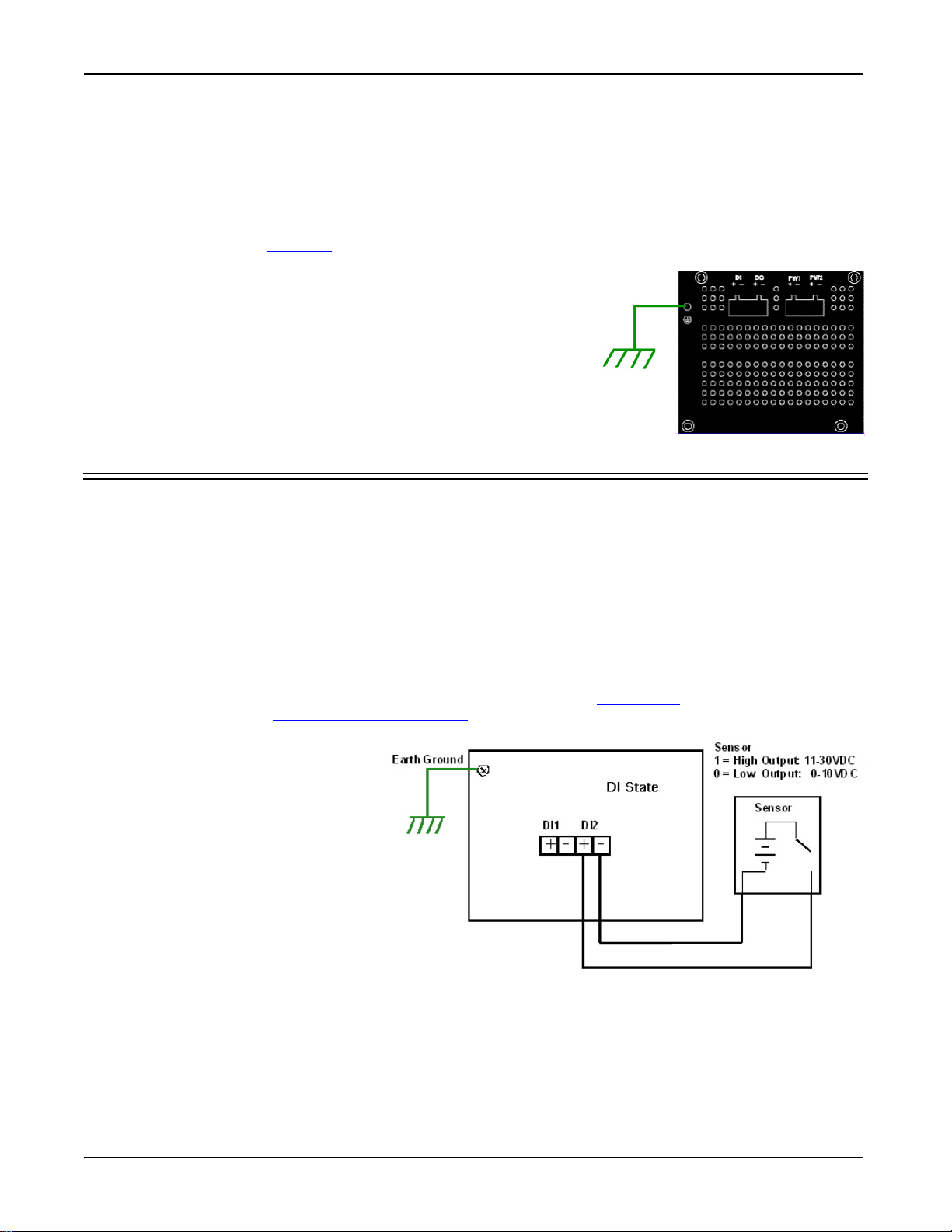
2. Connect a ground wire between the chassis and earth ground using
12-24AWG wire to ensure that the ES8510-XTE is not damaged by
noise or electrical shock.
a. Loosen the chassis ground screw on the bottom of the
ES8510-XTE.
b. Insert the ground wire.
c. Tighten the ground screw after the earth ground wire is
connected.
Connect the Digital Input s and Relay Outputs
The ES8510-XTE provides two digital inputs and two digital outputs (dry relay output) on terminal block
connectors on the bottom of the unit. The fault conditions can be configured in the web user interface or
Command Line Interface (CLI) and include:
•DI State
• Power failure
• Ethernet port link break
•Dry output
• Ping failure
• Super Ring failure
You can configure events using one of the ES8510-XTE user interfaces (Fault Relay
Command Line Interface (Global Configuration Mode
on Page 133).
The Digital Input pin can be pulled high
or low so that the connected equipment
can actively drive these pins. The web
user interface allows you to read and set
the value to the connected device. The
power input voltage of logic low is 0 to
10VDC and logic high is 11 to 30VDC.
Do not apply a higher voltage than the
specification; it may cause internal
circuit damage or a cause an incorrect
DI action.
on Page 109) or the
10 - Connect the Digital Input s and Relay Outputs RocketLinx ES8510-XTE User Guide: 2000574 Rev. C
Page 11
Hardware Installation
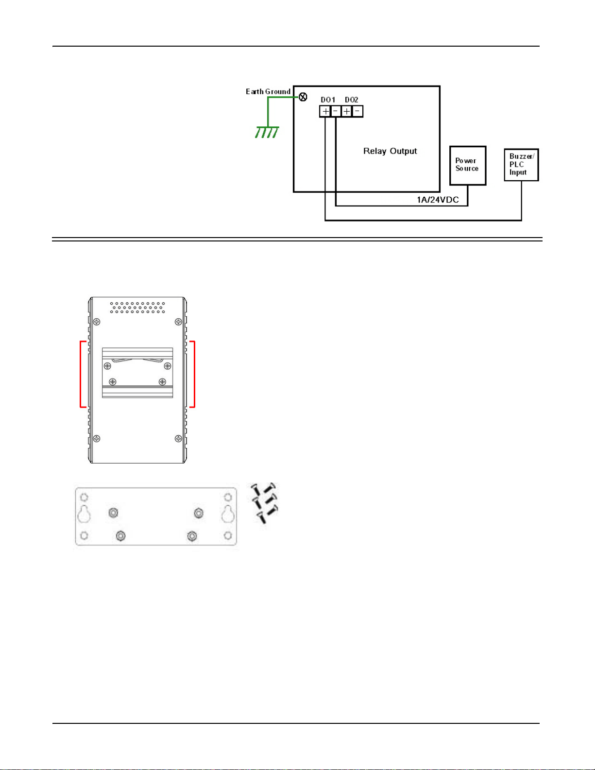
Digital Output
1. If necessary, use the screws to attach DIN rail clip to the rear
panel of the ES8510-XTE. (To remove DIN rail clip, reverse Step
1.)
2. Insert the upper end of DIN rail clip into the back of DIN rail
track from its upper side.
3. Lightly push the bottom of DIN rail clip into the track.
4. Verify that the DIN rail clip is tightly attached on the track.
5. To remove the ES8510-XTE from the track, reverse the steps
above.
DIN Rail Mounting
Follow the steps below to install the ES8510-XTE with the wall mounting plate:
1. To remove the DIN rail clip from the ES8510-XTE, loosen the screws from the DIN rail
clip.
2. Place the wall mounting plate on the rear panel of the ES8510-XTE.
3. Use the screws to attach the wall mounting plate to the ES8510-XTE.
4. Use the hook holes at the corners of the wall mounting plate to hang the ES8510-XTE
onto the wall.
5. To remove the wall mounting plate, reverse the steps above.
Wall Mount Installation
Digital output relay contacts are
energized (open) for normal operation
and close for fault conditions. The
digital output relay contacts support up
to 1A at 30VDC. Do not apply voltage
and current higher than the
specifications.
1. Insert the positive and negative
wires (12-24 AWG) into V+ and V-.
2. Tighten the wire-clamp screws to
prevent the wires from coming
loose.
Mount the ES8510-XTE
You can use the following procedure to mount the ES8510-XTE on a DIN rail or on the wall.
The DIN rail clip is already attached to the ES8510-XTE. If the DIN rail clip is not screwed onto the
ES8510-XTE, follow the instructions and the figure below to attach DIN rail clip to the ES8510-XTE.
RocketLinx ES8510-XTE User Guide: 2000574 Rev. C Mount the ES8510-XTE - 11
Page 12
Hardware Installation
Switch
3 TD+
6 TD-
1 RD+
2 RD-
3 RD+
6 RD-
1 TD+
2 TD-
Router or PC
Switch
3 TD+
6 TD-
1 RD+
2 RD-
3 TD+
6 TD-
1 RD+
2 RD-
Switch
Straight-Through Cabling Crossover Cabling
100BASE-TX
10BASE-TX
The SFP cage is 2 x1 design.
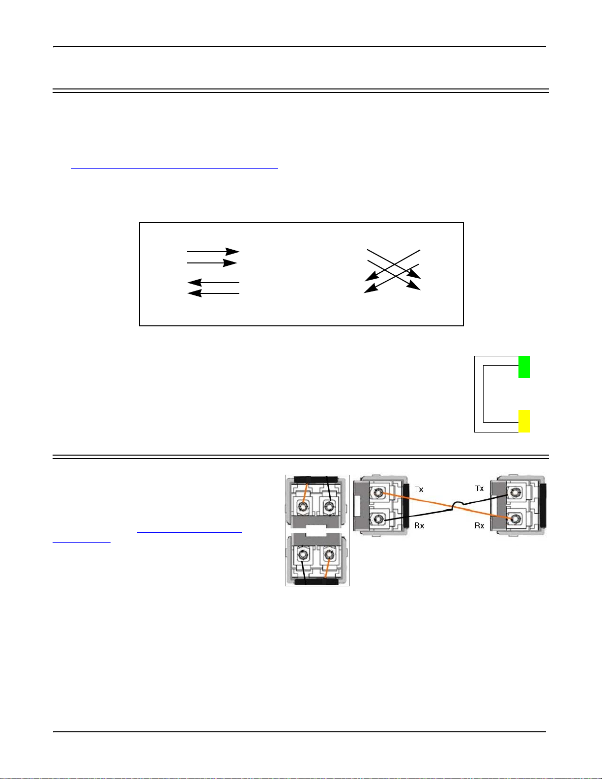
Connect the Ethernet Ports
You can use the following information to connect standard Ethernet cables between the ES8510-XTE
Ethernet ports and the network nodes.
• Ports 1-7 are Fast Ethernet (10/100BASE-TX) ports.
• Ports 8-10 are RJ45/SFP Combo ports that support (10/100BASE-TX / 100BASE-FX)
See Connect SFP Transceivers (Combo Ports 8-10) on Page 12 for information about SFP installation.
All of the Ethernet ports automatically detect the signal from the connected devices to negotiate the link
speed and duplex mode (half- or full-duplex). Auto MDI/MDIX allows you to connect another switch, hub, or
workstation without changing straight-through or crossover cables. Crossover cables cross-connect the
transmit lines at each end to the received lines at the opposite end.
.
Connect one side of an Ethernet cable into any switch port and connect the other side to
your attached device. The LNK/ACT LED is lit when the cable is correctly connected.
Always make sure that the cables between the switches and attached devices (for example,
switch, hub, or workstation) are less than 100 meters (328 feet) and meet these
requirements.
• 10BASE-T: Category 3, 4, or 5 cable
• 100BASE-TX: Category 5 or 5e cable
Connect SFP Transceivers (Combo Ports 8-10)
The ES8510-XTE equips three SFP ports
combined with RJ45 Fast Ethernet ports (Ports
8-10), The SFP ports accept standard mini GBIC
SFP transceivers. that support 100BASE-FX.
To ensure system reliability, Comtrol
recommends using Comtrol certified SFP
Transceivers.
1. Plug the SFP transceiver into the SFP fiber
transceiver.
2. Connect the transmit channel to the receive
channel at each end.
3. Check the direction/angle of the fiber transceiver and the fiber cable.
Note: This is a Class 1 Laser/LED product. Do not stare at the Laser/LED Beam.
The SFP port does not function until the fiber cable is linked to another active device. The SFP and
corresponding RJ45 ports work in an exclusive mode. Traffic sent or received through the SFP module has
priority thus no traffic is sent or received over the corresponding RJ45 connection. To use the RJ45
connection, remove the corresponding SFP.
Multi-Mode cables should not exceed 2KM and Single-Mode cables should not exceed 30km.
12 - Connect the Ethernet Ports RocketLinx ES8510-XTE User Guide: 2000574 Rev. C
Page 13

Hardware Installation
Link/
Speed
LED Descriptions
This subsection provides information about the ES8510-XTE LEDs. You can also refer to Device Front Panel
on Page 122 for information about using the web user interface to remotely view LED information.
LED Name LED On LED Blinking LED Off
Power 1
Green: Power available No power
Power 2
DO1 (Digital Output)
Red: DO activated DO not activated
DO2 (Digital Output)
DI1 (Digital Input)
Green: DI activated DI not activated
DI2 (Digital Input)
R.M. (ring master) Green: Working as a Ring
Master
1 - 7
Green: Linked to another
device
Amber: Full-Duplex
8 - 10
SFP
RJ45
Green: Connected
Green: Active connection
Green: Ring failed Ring function disabled or
the ES8510-XTE is on a
ring but not the ring
master
Green: Active traffic
Not connected
Collision
Green: Active
connection
Green: Active
Plugged in but not linked
up
Not connected
connection
RocketLinx ES8510-XTE User Guide: 2000574 Rev. C LED Descriptions - 13
Page 14

Hardware Installation
Combo Port
LEDs
SFP Ports
Combo Ports
10/100BASE-TX
RS-232 Console
Port
100BASE-FX
Reset Button
Fast Ethernet Ports
10/100BASE-TX
Fast Ethernet Ports
Panel Layout
The ES8510-XTE provides ten 10/100BASE-TX ports of which three are Combo ports (RJ45/SFP).
Reset Button
The ES8510-XTEhas a reset button that you can use to reboot the ES8510-XTE or reset the configuration to
the factory default.
Reset Button Description
Depress 5 Seconds
Depress > 10
Seconds
This reboots the ES8510-XTE without changing the
configuration.
This loads the factory default configuration values into the
ES8510-XTE including the IP address.
The Reset button is located on the front panel of the ES8510-XTE to the right of the RS LED.
14 - Panel Layout RocketLinx ES8510-XTE User Guide: 2000574 Rev. C
Page 15

Using PortVision DX
There are several ways to configure network information. Comtrol Technical Support recommends connecting
the ES8510-XTE to a PC or laptop running Windows
This section shows how to use PortVision DX for initial network configuration and discusses how to:
• Install PortVision DX (Page 17
• Configure the network address (Page 19
• Check the firmware and bootloader version on the ES8510-XTE to verify that the latest versions are
loaded (Page 22
• Download the latest version firmware and bootloader and upload it to the ES8510-XTE (Page 23
• Perform other PortVision DX tasks, such as:
- Adding a new RocketLinx (managed or unmanaged) or a third party device to PortVision DX to
maintain device information on your network (
- Using configuration files for use in configuring multiple installations with the same features (Page 26)
- Using the LED Tracker (Page 27)
• Organize how PortVision DX displays your Comtrol Ethernet attached products (Page 26)
• Access the latest documentation for your Comtrol Ethernet attached product
Optionally, you can use the web user interface or the CLI to perform these tasks on the ES8510-XTE using
these subsections:
• IP Configuration
• Firmware Upgrade
• Basic Settings (CLI)
) before configuration
on Page 47
on Page 61
on Page 138
)
)
and installing PortVision DX for initial configuration.
)
Page 25)
NetVision
NetVision, the configuration utility that only supported RocketLinx has been replaced by PortVision DX,
which supports all Comtrol Ethernet attached products.
If you are familiar with NetVision and wish to use it, NetVision
status, meaning that it is no longer being maintained. If any bugs or issues exist, Technical Support will have
you load and use PortVision DX.
is still available but has been moved to Legacy
RocketLinx ES8510-XTE User Guide: 2000574 Rev. C Using PortVision DX - 15
Page 16

Using PortVision DX
PortVision DX Overview
PortVision DX automatically detects Comtrol Ethernet attached products physically attached to the local
network segment so that you can configure the network address, upload firmware, and manage the following
products:
• RocketLinx switches
• DeviceMaster family
- DeviceMaster PRO
- DeviceMaster RTS
- DeviceMaster Serial Hub
- DeviceMaster 500
•DeviceMaster UP
•DeviceMaster LT
• IO-Link Master family
In addition to identifying Comtrol Ethernet attached products, you can use PortVision DX to display any
third-party switch and hardware that may be connected directly to those devices. All non-Comtrol products
and unmanaged RocketLinx switches are treated as non-intelligent devices and have limited feature support.
For example, you cannot configure or update firmware on a third-party switch.
PortVision DX Requirements
Use PortVision DX to identify, configure, update, and manage the ES8510-XTE on the following Windows
operating systems:
• Windows 8/8.1
• Windows Server 2012
•Windows 7
• Windows Server 2008
•Windows Vista
• Windows Server 2003
•Windows XP
PortVision DX requires that you connect the Comtrol Ethernet attached product to the same network segment
as the Windows host system if you want to be able to scan and locate it automatically during the configuration
process.
16 - PortVision DX Overview RocketLinx ES8510-XTE User Guide: 2000574 Rev. C
Page 17

Using PortVision DX
Installing PortVision DX
During initial configuration, PortVision DX automatically detects and identifies ES8510-XTE switches, if they
are in the same network segment.
Use the Software and Documentation CD that came with the ES8510-XTE to check for the latest version of
PortVision DX or use the link below to download the latest version.
1. Locate PortVision DX using one of the following methods to download the latest version:
• Software and Documentation CD: You can use the CD menu system to check the version on the CD
against the latest released version.
• FTP site subdirectory:
ftp://ftp.comtrol.com/rocketlinx/portvision_dx
Note: Depending on your operating system, you may need to
respond to a Security Warning to permit access.
2. Execute the PortVision_DX[version].msi file.
3. Click Next on the Welcome screen.
.
4. Click I accept the terms in the License Agreement and Next.
5. Click Next or optionally, browse to a different location and
then click Next.
RocketLinx ES8510-XTE User Guide: 2000574 Rev. C Installing PortVision DX - 17
Page 18
Using PortVision DX
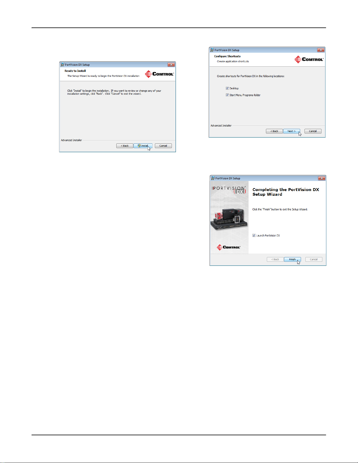
6. Click Next to configure the shortcuts.
7. Click Install.
8. Depending on the operating system, you may need to click Ye s to the Do you want to allow the following
program to install software on this computer? query.
9. Click Launch PortVision DX and Finish in the last
installation screen.
10. Depending on the operating system, you may need to click
Ye s to the Do you want to allow the following program to
make changes to this computer? query.
11. Go the next subsection to use PortVision DX to program the
network information.
18 - Installing PortVision DX RocketLinx ES8510-XTE User Guide: 2000574 Rev. C
Page 19

Using PortVision DX
You can save time if you only scan for RocketLinx switches.
Configuring the Network Settings
The ES8510-XTE has the following default values when shipped from the factory:
• IP address: 192.168.250.250
• Subnet mask: 255.255.0.0
• Gateway address: 192.168.250.1
Use the following procedure to change the default network settings on the ES8510-XTE for your network.
1. If necessary, start PortVision DX using the PortVision DX desktop shortcut or from the Start button, click
All Programs > Comtrol > PortVision DX > PortVision DX.
Note: Depending on your operating system, you may need to click Ye s to the Do you want to allow the
following program to make changes to this computer? query.
2. Click the Scan button in the Toolbar.
3. Select the Comtrol Ethernet attached products that you want to locate and then click Scan.
Note: If the Comtrol Ethernet attached product is not on the local segment and it has been programmed
with an IP address, it will be necessary to manually add the Comtrol Ethernet attached product to
PortVision DX.
RocketLinx ES8510-XTE User Guide: 2000574 Rev. C Configuring the Network Settings - 19
Page 20

Using PortVision DX
4. Highlight the ES8510-XTE for which you want to program network information and open the Properties
screen using one of these methods.
• Double-click the ES8510-XTE in the Device Tree or Device List pane.
• Highlight the ES8510-XTE in the Device Tree or Device List pane and click the Properties button.
• Right-click the ES8510-XTE in the Device Tree or Device List pane and click Properties in the popup
menu
• Highlight the ES8510-XTE, click the Manage menu and then Properties.
20 - Configuring the Network Settings RocketLinx ES8510-XTE User Guide: 2000574 Rev. C
Page 21

Using PortVision DX
5. Optionally, rename the ES8510-XTE in the Device Name field for a PortVision DX friendly name. The
default name displays as Device and the last three sets of hex numbers from the MAC address.
Note: The MAC address and Device Status fields are automatically populated and you cannot change
these values.
6. Optionally, enter the serial number, which is on a label on the ES8510-XTE.
7. Select DHCP IP or Static IP for the IP Mode.
• If you select DHCP IP, go to Step 8
.
• If you select Static IP:
- Enter a unique IP address as required for your site.
- Enter a valid Subnet Mask value for your network.
- Enter a valid Default Gateway value for your network.
8. Optionally, select the Network Topology type, which is an informational field.
9. Click Apply Changes to update the network information on the ES8510-XTE.
Note: If you are deploying multiple ES8510-XTE switches that share common values, you can save the
configuration file and load that configuration onto other ES8510-XTE switches. See Using
Configuration Files on Page 26 for more information.
10. Click Close to exit the Properties window.
11. You should verify that you have the latest firmware loaded on the ES8510-XTE because a newer version
typically includes feature enhancements and bug fixes. Refer to Checking the Firmware Version
22 and if necessary, Uploading the Latest Firmware
or Bootloader on Page 23.
on Page
12. If you have the latest firmware, you can begin feature configuration, see one of these sections:
• Configuration Using the Web User Interface
• Configuration Using the Command Line Interface (CLI)
on Page 31
on Page 125
• Right-click the ES8510-XTE in the Device List pane and click Webpage in the popup menu.
Note: The default User Name and Password are both admin.
RocketLinx ES8510-XTE User Guide: 2000574 Rev. C Configuring the Network Settings - 21
Page 22

Using PortVision DX
Checking the Firmware Version
Checking your web interface and bootloader versions is easy in PortVision DX.
Comtrol recommends loading the latest firmware and bootloader so that you have all of the latest feature
enhancements and bug fixes.
1. If the ES8510-XTE is not displayed in PortVision DX, click the
Scan button.
2. Select the Comtrol Ethernet attached product type and click the
Scan button.
3. Locate the ES8510-XTE in the Device List pane. Under
Software Version:
• The first number reflects the firmware version.
• The second number displays the bootloader version.
4. Check the Comtrol ftp
site for the latest firmware and bootloader. Simply, click your product type and click
the Software link and check the latest version against the version on the ES8510-XTE.
Use the next subsection for procedures to upload the firmware (web interface) and bootloader.
22 - Checking the Firmware Version RocketLinx ES8510-XTE User Guide: 2000574 Rev. C
Page 23

Using PortVision DX
Uploading the Latest Firmware or Bootloader
You can use the following procedure to upload the latest firmware or bootloader.
1. If you have not done so, download the latest firmware and bootloader using the previous subsection.
2. Right-click the ES8510-XTE in the Device List pane that you want to update, click Advanced --> Upload
firmware.
3. Navigate to the location of the firmware files, select the appropriate file, and then click Open.
4. Click Ye s to the Upload Firmware message.
5. Click Ok to the message notifying you that you should
wait to use the ES8510-XTE when the status returns
to ON-LINE.
6. Right-click the ES8510-XTE in the Device List pane and click Refresh. Optionally, you can click the Refresh
button in the Toolbar and that refreshes all devices in PortVision DX.
7. Verify that the version change is reflected in under the Software Version.
RocketLinx ES8510-XTE User Guide: 2000574 Rev. C Uploading the Latest Firmware or Bootloader - 23
Page 24

Using PortVision DX
Uploading Firmware to Multiple ES8510-XTE Switches
You can use this procedure if your ES8510-XTE is connected to the host PC, laptop, or if the ES8510-XTE
resides on the local network segment.
Note: Technical support does not advise uploading bootloader to multiple ES8510-XTE switches. Remember
that uploading firmware reboots the ES8510-XTE, which depending on your network connections may
cause firmware uploading to fail on another ES8510-XTE.
1. If the ES8510-XTE is not displayed in PortVision DX, click the
Scan button.
2. Select the Comtrol Ethernet attached product type and click the
Scan button.
3. Shift-click the multiple ES8510-XTE switches on the Main
screen that you want to update and use one of the following
methods:
•Click the Upload button.
• Right-click and then click Advanced > Upload Firmware.
•Click Advanced >Upload Firmware in the Manage menu.
4. Browse, click the firmware (.bin) file, Open (Please locate the new firmware), and then click Yes (Upload
Firmware).
It may take a few minutes for the firmware to upload onto all of the ES8510-XTE switches. The
ES8510-XTE reboots itself during the upload process.
5. Click Ok to the advisory message about waiting to use the device until the status reads ON-LINE.
24 - Uploading Firmware to Multiple ES8510-XTE Switches RocketLinx ES8510-XTE User Guide: 2000574 Rev. C
Page 25

Using PortVision DX
In the next polling cycle, PortVision DX updates the Device List pane and displays the new firmware version.
Adding a New Device in PortVision DX
You can add a new ES8510-XTE manually, if you do not want to scan the network to locate it or you want to
pre-configure an ES8510-XTE before connecting it to the network. Optionally, you can also add unmanaged
devices or RocketLinx switches to maintain information about devices on the network.
See the PortVision DX help system for additional information about adding unmanaged RocketLinx switches
or third party devices or switches.
Use the following procedure to add a remote ES8510-XTE to PortVision DX.
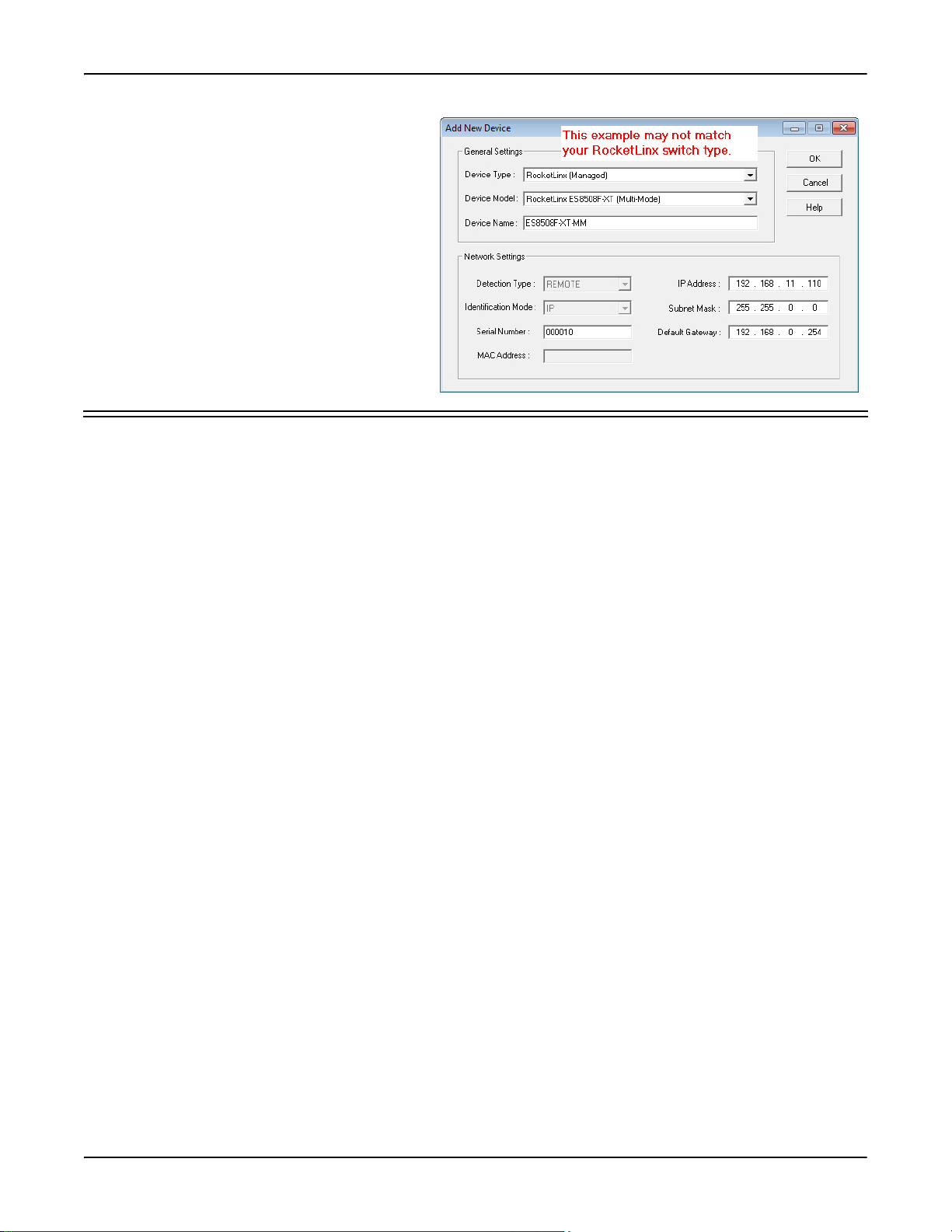
1. Access the New Device window using one of these methods:
•Click Add New > Device in the Manage menu.
• Right-click a folder or a RocketLinx switch in the Device Tree pane and click Add New > Device.
2. Select the appropriate RocketLinx in the Device Type drop list.
3. Select the appropriate model in the Device Model drop list.
4. Enter a friendly device name in the Device Name list box.
5. Optionally, enter the serial number in the Serial Number list box.
RocketLinx ES8510-XTE User Guide: 2000574 Rev. C Adding a New Device in PortVision DX - 25
Page 26
Using PortVision DX
6. Enter the IP Address for the ES8510-XTE.
It is not necessary to enter the Subnet Mask
and Default Gateway
7. Click Ok to close the Add New Device
window. It may take a few moments to save
the ES8510-XTE.
8. If necessary, click Refresh for the new
RocketLinx to display in the Device Tree or
Device List panes. The RocketLinx shows
OFF-LINE if it is not connected to the local
network or if an incorrect IP address was
entered.
Using Configuration Files
If you are deploying multiple ES8510-XTE switches that share common firmware values, you can save the
configuration file (.dc) from the Main screen in PortVision DX and load that configuration onto other
ES8510-XTE switches.
Saving a Configuration File
Use this procedure to save a configuration file.
1. Highlight the ES8510-XTE in the Device List pane and use one of the following methods:
•Click the Save button.
• Right-click and then click Configuration > Save.
2. Browse to the location you want to save the file, enter a file name, and click Save.
3. Click Ok to close the Save Configuration Completed message.
Loading a Configuration File
Use the following procedure to load a previously saved a ES8510-XTE configuration file. Load a configuration
file and apply it to a selected ES8510-XTE switch or switches from the Device List pane.
Use this procedure to load a configuration file using the Device List pane to one or more ES8510-XTE
switches.
1. Highlight the device or devices in the Device List pane and use one of the following methods:
•Click the Load button
• Right-click and then click Configuration > Load
2. Click Ye s to the warning that it will take 25 seconds per device and it may also reboot the devices.
3. Browse to the location of the configuration file, click the file name (.dc) and then Open.
4. Close the Load Configuration popup message.
26 - Using Configuration Files RocketLinx ES8510-XTE User Guide: 2000574 Rev. C
Page 27
Using PortVision DX
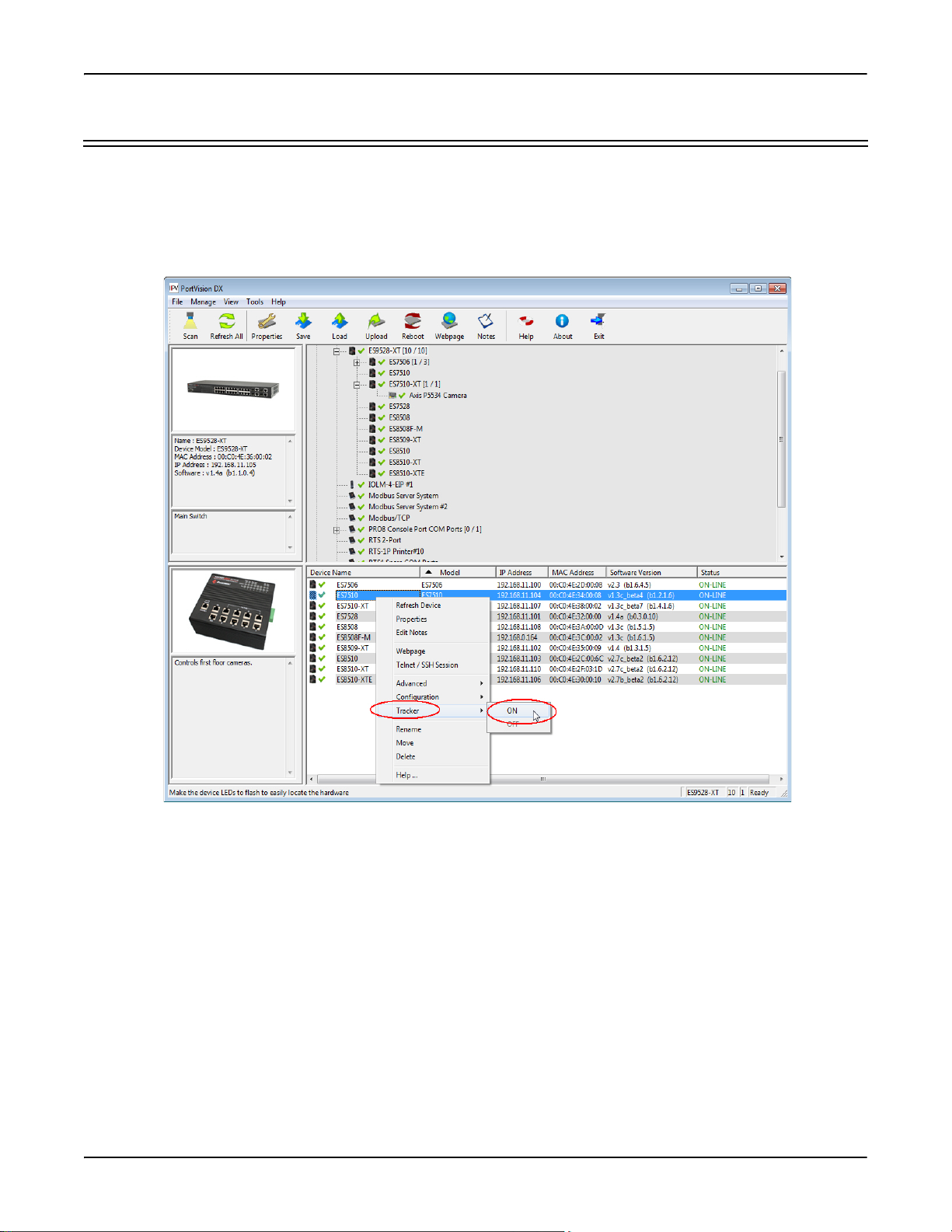
Using the LED Tracker
RocketLinx managed switches support the LED Tracker feature, which allows you to toggle on/off the LEDs
on a specific device so that you can locate the physical unit.
Use this procedure to toggle the LED Tracker feature on RocketLinx switches.
1. Right-click the ES8510-XTE in the Device List pane, click Tracker, and then click ON.
The ES8510-XTE SYS LED will flash for five seconds.
2. If necessary, you may need to click Trac ker and ON several times to catch the flashing SYS LED.
RocketLinx ES8510-XTE User Guide: 2000574 Rev. C Using the LED Tracker - 27
Page 28

Using PortVision DX
Customizing PortVision DX
You can customize how PortVision DX displays the devices. You can even create sessions tailored for specific
audiences. You can also add shortcuts to other applications using Tools > Applications > Customize feature.
The following illustrates how you can customize your view.
See the PortVision DX Help system for detailed information about modifying the view. For example, the above
screen shot illustrates devices layered in folders.
28 - Customizing PortVision DX RocketLinx ES8510-XTE User Guide: 2000574 Rev. C
Page 29
Using PortVision DX
Accessing RocketLinx Documentation from PortVision DX
You can use this procedure in PortVision DX to download and open the previously downloaded documents for
the RocketLinx.
How to Download Documentation
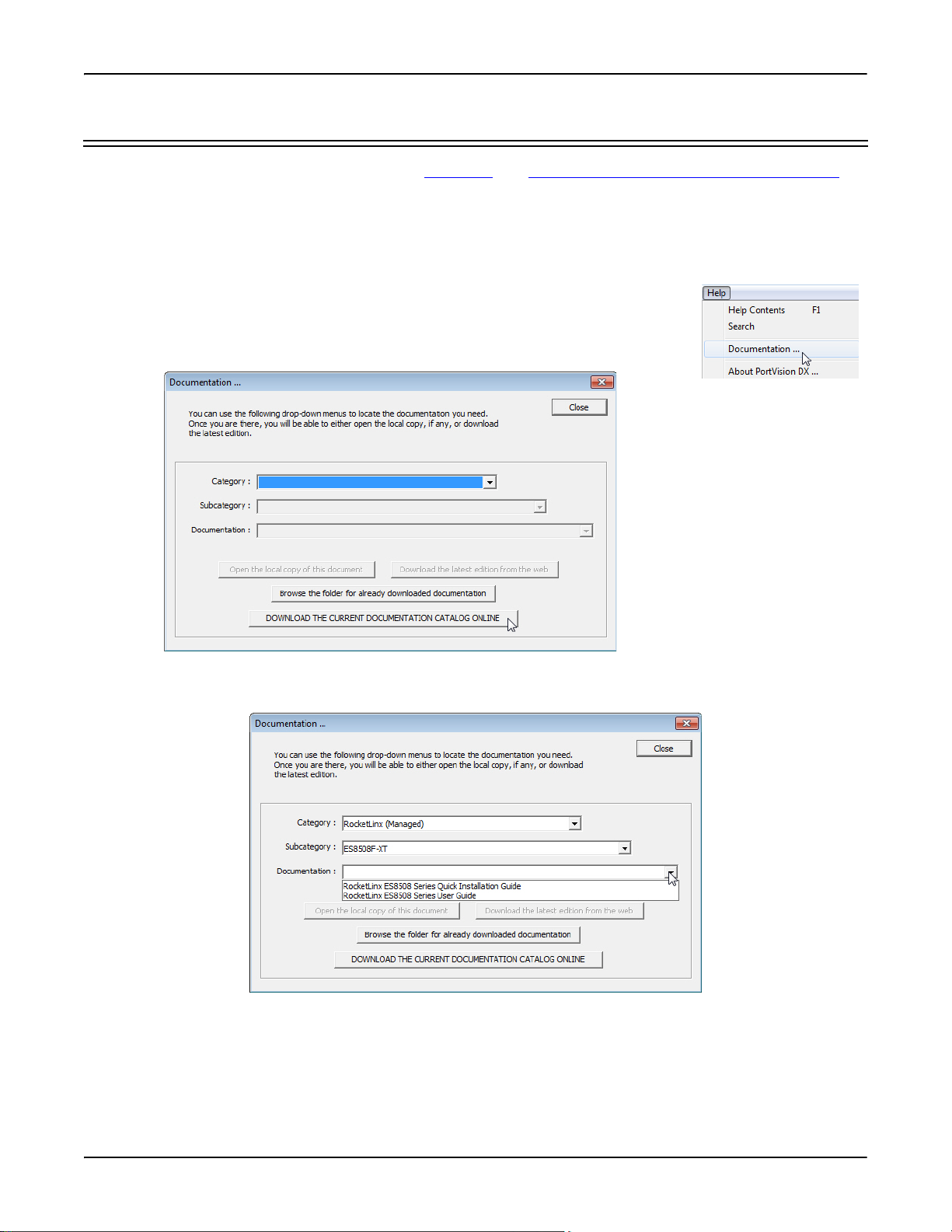
Use this procedure to initially download a document or documents.
1. If necessary, open PortVision DX.
2. Click Help > Documentation.
3. Optionally, click the DOWNLOAD THE CURRENT DOCUMENTATION CATALOG
ONLINE button to make sure that the latest documentation is available to
PortVision DX.
4. Select the product Category from the drop list.
5. Select the document you want to download from the Documentation drop list.
Note: This image may not reflect your RocketLinx.
6. Click the Download the latest edition from the web button.
Note: It may take a few minutes to download, depending on your connection speed. The document opens
automatically after it has downloaded.
7. Click Close if you have downloaded all of the documents that you wanted.
RocketLinx ES8510-XTE User Guide: 2000574 Rev. C Accessing RocketLinx Documentation from PortVision DX - 29
Page 30
Using PortVision DX
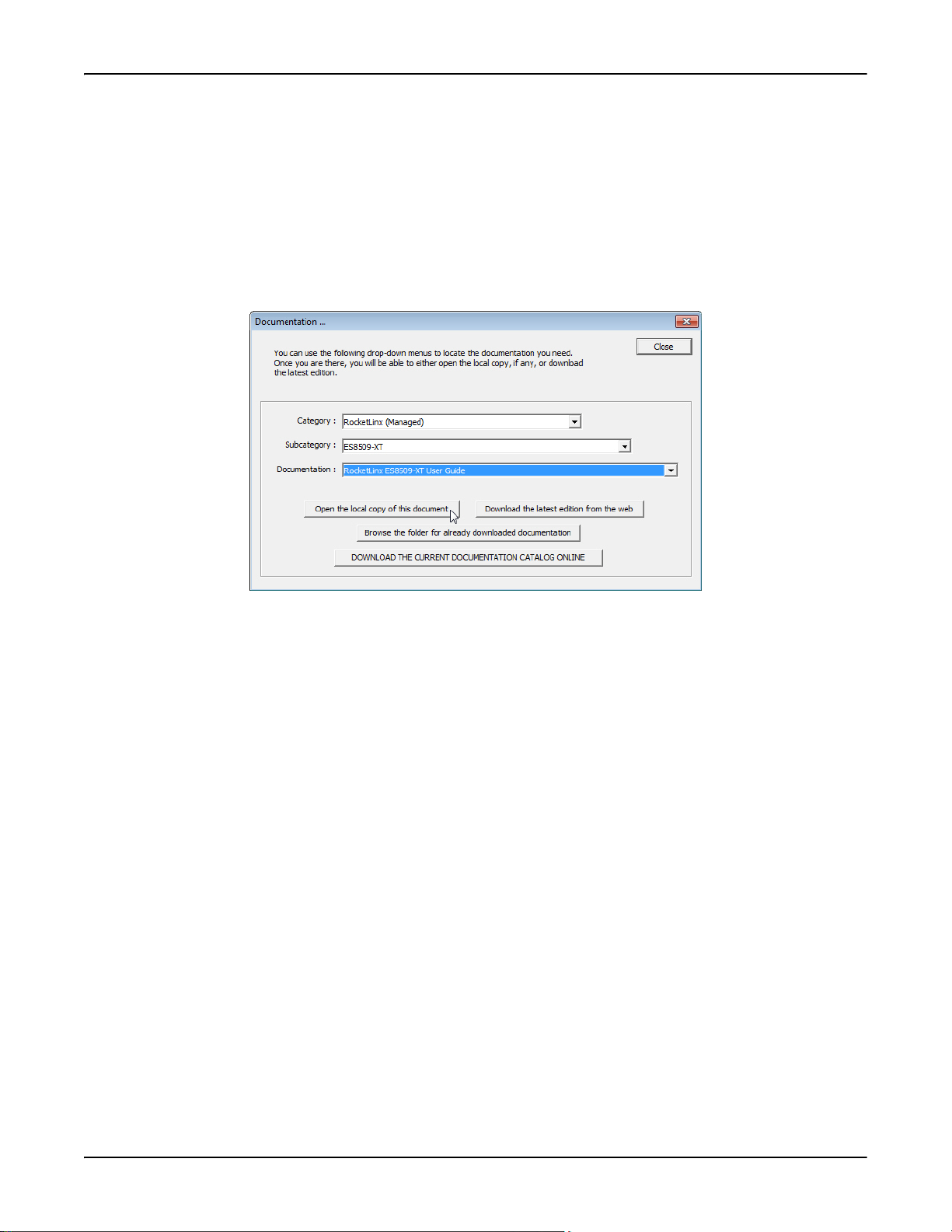
How to Open Previously Downloaded Documents
Use the following procedure to access previously downloaded documents in PortVision DX.
Note: Optionally, you can browse to the Program Files (x86) > Comtrol > PortVision DX > Docs subdirectory and
open the document.
1. If necessary, open PortVision DX > Start/Programs > Comtrol > PortVision DX > PortVision DX or use the
desktop shortcut.
2. Click Help > Documentation.
3. Click the Open the local copy of the document button to view the document.
Note: This image may not reflect your RocketLinx.
Note: If the document fails to open, it may be that your browser has been disabled. You can still access the
document by clicking the Browse the folder for already downloaded documentation button and opening
the document with your custom browser.
4. Click Close in the Documentation... popup, unless you want to open or download other documents.
30 - How to Open Previously Downloaded Documents RocketLinx ES8510-XTE User Guide: 2000574 Rev. C
Page 31

Configuration Using the Web User Interface
The ES8510-XTE provides in-band and out-band configuration methods:
• Out-band management means that you configure the ES8510-XTE using the RS-232 console cable and the
Command Line Interface (CLI) to access the ES8510-XTE without attaching an admin PC to the network.
You can use out-band management if you lose the network connection to the ES8510-XTE. The CLI and
Telnet are discussed in
• In-band management means that you connect remotely using the ES8510-XTE IP address through the
network. You can remotely connect with the ES8510-XTE embedded Java applet web user interface or a
Telnet console and the CLI. The ES8510-XTE provides HTTP web user interface (
HTTPS web user interface (Page 34) for web management.
Configuration Overview
This subsection discusses a minimum level of configuration required to operate the ES8510-XTE.
1. If you have not done so, install the hardware, see Hardware Installation on Page 9.
2. If you are planning on using in-band management, you need to program the ES8510-XTE IP address to
meet your network requirements. The easiest way to configure the IP address is using a Windows system
and PortVision DX, see
3. Configure other features as desired. You can refer to the Feature Overview on Page 37 to locate
configuration information or use these links:
• Basic Settings on Page 45
• Port Configuration on Page 64
• Network Redundancy on Page 70
• VLAN on Page 84
• Private VLAN on Page 91
• Traffic Prioritization on Page 94
• Multicast Filtering on Page 97
• SNMP on Page 100
• Security on Page 103
• Warning on Page 109
• Monitor and Diag on Page 115
• Device Front Panel on Page 122
• Save to Flash on Page 123
• Logout on Page 123
Configuration Using the Command Line Interface (CLI) on Page 125.
Page 32) and secure
Configuring the Network Settings on Page 19.
RocketLinx ES8510-XTE User Guide: 2000574 Rev. C Configuration Using the Web User Interface - 31
Page 32

Configuration Using the Web User Interface
Web User Interface
The ES8510-XTE web management page was developed with Java. You can use any standard web browser,
which is compatible with the Java Runtime to configure and communicate with the ES8510-XTE from
anywhere on the network.
If you did not program the IP address for your network using PortVision DX (Programming Network
Information on Page 20), you need to change your computer IP address to 192.168.250.x (Network Mask:
255.255.0.0). The default IP address for the ES8510-XTE is 192.168.250.250.
1. If necessary, install the latest version of the Java Runtime Environment.
Note: You will need to update to the latest Java version to run the web interface.
2. Open a command prompt window and ping the IP address for the ES8510-XTE to verify a normal
response time.
3. Launch the web browser on the PC using one of these methods:
• Right-click the ES8510-XTE in PortVision DX and click Webpage.
•Type http://192.168.250.250 (or the IP address of the switch), and then press Enter.
Note: Since Java is constantly updated, the prompts may be different from what the following subsections
display.
Windows XP - Windows Server 2003
If a Warning - Security message appears, click Always trust content from this publisher and then Run when
requested to run the application (IP address).
Windows Vista - Windows 8.1
If necessary, click I accept the risk and want to run this application, and then Run if a security warning popup
message appears.
32 - Web User Interface RocketLinx ES8510-XTE User Guide: 2000574 Rev. C
Page 33

4. Enter the user name, the password, and click OK. The
default user name and password are both admin.
The Welcome page of the web management interface
then appears.
Configuration Using the Web User Interface
5. If you have not done so, you can change the ES8510-XTE IP address to meet your network environment.
a. Double-click Basic Setting.
b. Click IP Configuration.
To use static addressing, enter a valid IP add dress, subnet mask and default gateway.
To use DHCP, click Enable in the DHCP Client drop list.
c. Click Apply.
You can use the Feature Overview on Page 37 to locate other features that you may want to configure.
RocketLinx ES8510-XTE User Guide: 2000574 Rev. C Web User Interface - 33
Page 34

Configuration Using the Web User Interface
Secure Web User Interface
The ES8510-XTE web user interface also provides secured management through an HTTPS login so that all
of the configuration commands are secure.
If you did not program the IP address for your network using PortVision DX (Configuring the Network
Settings on Page 19), you need to change your computer IP address to 192.168.250.x (Network Mask:
255.255.0.0). The default IP address for the ES8510-XTE is 192.168.250.250.
1. Open a command prompt window and ping the IP address for the ES8510-XTE to verify a normal
response time.
2. Launch the web browser and type https://192.168.250.250 (or the IP address of the ES8510-XTE).and then
press Enter.
3. Click Continue to the web site (not recommended).
34 - Secure Web User Interface RocketLinx ES8510-XTE User Guide: 2000574 Rev. C
Page 35

Windows XP and Windows Server 2003
a. Click No when the popup screen
appears and requests you to trust the
secured HTTPS connection distributed
by the ES8510-XTE.
b. Click Always trust content from this
publisher and then Run when requested
to run the application (IP address) in
the Warning - Security message.
Windows Vista - Windows 7
a. Click the Continue button.
Configuration Using the Web User Interface
b. If necessary, click Show all content.
c. If desired, click Do not show this again for apps from the publisher and location above and then click Run if
a security warning popup message appears.
RocketLinx ES8510-XTE User Guide: 2000574 Rev. C Secure Web User Interface - 35
Page 36

Configuration Using the Web User Interface
4. Enter the user name and the password and click OK. The default user name and password are both
admin.
The Welco me page of the web management interface then appears.
5. If you have not done so, you can change the ES8510-XTE IP address to meet your network environment.
a. Double-click Basic Setting.
b. Click IP Configuration.
- To use static addressing, enter a valid IP address, subnet mask and default gateway.
- To use DHCP, click Enable in the DHCP Client drop list.
c. Click Apply.
You can use the Feature Overview on Page 37 to locate other features that you may want to configure.
36 - Secure Web User Interface RocketLinx ES8510-XTE User Guide: 2000574 Rev. C
Page 37

Configuration Using the Web User Interface
Feature Overview
The following table provides detailed information about ES8510-XTE features and provides the location of the
configuration information in the web user interface.
Type Category Details
• System Authentication Control - Enable/Disable
• Authentication Method - RADIUS or Local
802.1x Port-Based
Network Access
Control
Configuration
802.1x Port-Based
Network Access
Control Port
Configuration
802.1x
Configuration on
Page 105
802.1x Port
Configuration on
Page 106
• RADIUS Server - IP Address, Shared Key, Server Port,
and Accounting Port
• Local RADIUS User - User Name, Password, and VID
• Secondary RADIUS Server - IP Address, Shared Key,
Server Port, and Accounting Port
• Local RADIUS User List
Port Configuration
• Port Control - Auto, Forced Authorized, or Force
Unauthorized
• Re-authentication - Enable/Disable
• Maximum Request
• Guest VLAN
• Host Mode - Single/Multi
• Admin Control Direction - Both or In
Timeout Configuration
•Port by Port
• Re-Authentication Periods
• Quiet Period
•Tx Period
• Supplicant Timeouts
• Server Timeouts
•Port by Port
802.1x Port-Based
Network Access
Control Port Status
802.1x Port Status
on Page 108
•Port Control
• Authorize Status
• Authorized Supplicant
• Oper Control Direction
•Admin
• RADIUS Server (RADIUS Server IP, Shared Key, and
Server Port)
Admin Password
Admin Password
on Page 46
• Secondary RADIUS Server (RADIUS Server IP, Shared
Key, and Server Port)
Backup and Restore
RocketLinx ES8510-XTE User Guide: 2000574 Rev. C Feature Overview - 37
Backup and
Restore on Page 57
Local or TFTP
Page 38

Configuration Using the Web User Interface
Type Category Details
CoS-Queuing
Mapping
DHCP Server
Configuration
DSCP-Queuing
Mapping
Event Selection
CoS-Queue
Mapping on Page
95
DHCP Server
Configuration on
Page 52
DHCP Leased
Entries on Page 54
DHCP Relay Agent
on Page 55
DSCP-Queue
Mapping on Page
96
Event Selection on
Page 112
• CoS 0 through 7
• Queue 0 through 3
• Queue 3 highest priority
• DHCP Server Configuration
- Excluded Addresses and Manual Binding
- Port and IP Address
- Option 82
• DHCP Leased Entries
•DHCP Relay Agent
- Helper Address 1-4
- DHCP Option82 Relay Agent (Circuit ID/Remote ID)
•DSCP 0 through 7
• Queue 0 through 3
• Queue 3 highest priority
• Device Cold Start
• Device Warm Start
• Authentication Failure
• Time Synchronization Failure
• Power 1 Failure
• Power 2 Failure
• Fault Relay
•DI1 Change
•DI2 Change
•Ring Event
• Loop Protection
•Ring Event
•SFP Failure
• Port by Port Event Selection
Relay 1- Multi-event
• DI - State (DI number and High or Low)
• Dry Output - On Period (Sec) and Off Period (Sec)
Faul t R e lay
Fault Relay on
Page 109
• Power Failure - Power 1 or Power 2
• Link Failure (Port or Ports)
• Ping Failure, IP Address, Reset Time (Sec), and Hold
Time (Sec)
• Super Ring Failure
38 - Feature Overview RocketLinx ES8510-XTE User Guide: 2000574 Rev. C
Page 39

Type Category Details
GVRP Configuration
GVRP
Configuration on
Page 89
Configuration Using the Web User Interface
•2K Entries
• Enable/Disable GVRP Protocol
• State - Enable/Disable
• Join Timer
• Leave Timer
• Leave All Timer
IGMP Query
IGMP Snooping
IP Configuration
IP Security
Loop Protection
MAC Address Table
(8K)
IGMP Query on
Page 99
IGMP Snooping on
Page 98
Basic Settings on
Page 45
IP Security on
Page 104
Loop Protection on
Page 83
MAC Address
Table on Page 115
• Version - Version 1, Version 2, or Disable
• Query Intervals
• Query Maximum Response Time
• Enable/Disable
•VID
• Port by Port IGMP Snooping Table
- IP Address
-VID
• IPv4 and IPv6 support
•DHCP
• DNS1 and DNS2
• Enable/Disable
•Security IP
• Security IP List - Index and Security IP
• Transmit Interval
• Enable/Disable port by port
• Status
• Aging Time (Sec)
• Static Unicast MAC Address - MAC Address, VID, and
Port
• Port by Port MAC Address Table View
- Static Unicast
- Dynamic Unicast
- Static Multicast
- Dynamic Multicast
• MSTP Region Configuration - Name and Revision
MSTP Configuration
MSTP
Configuration on
Page 75
• New MST Instance - Instance ID, VLAN Group, and
Instance Priority
• Current MST Instance Configuration - Instance ID,
VLAN Group, and Instance Priority
RocketLinx ES8510-XTE User Guide: 2000574 Rev. C Feature Overview - 39
Page 40

Configuration Using the Web User Interface
Type Category Details
MSTP Information
MSTP Port
Configuration
MSTP Information
on Page 79
MSTP Port
Configuration on
Page 78
• Instance ID
• Root Information
- Root Address
- Root Priority
- Root Port
- Root Path Cost
-Maximum Age
-Hello Time
-Forward Delay
•Port Information
- Role
-Port State
-Path Cost
-Port Priority
- Link Type
-Edge Port
Instance ID
•Port
•Path Cost
• Priority
• Link Type
•Edge Port
Ping Utility
Port Control
Port Mirror Mode
Port Security
Ping Utility on
Page 121
Port Control on
Page 64
Port Mirroring on
Page 118
Port Security on
Page 103
Target IP Address
• Enable/Disable Port State
• Speed/Duplex - Auto-Negotiation, 10 Full/Half, and 100
Full/Half
• Flow control - Disable/Symmetric
• User-Defined Description
• Port Mirror Mode - Enable/Disable
•Port by Port
- Source Port - Rx and Tx
- Destination Port - Rx and Tx
• Port Security State - Port by Port
• Add Port Security Entry - Port, VID, and MAC Address
• Port Security Entry List - Port VID, and MAC Address
40 - Feature Overview RocketLinx ES8510-XTE User Guide: 2000574 Rev. C
Page 41

Type Category Details
Port Statistics
Port Status
Port Statistics on
Page 117
Port Status on
Page 66
Configuration Using the Web User Interface
Port by Port
•Type
•Link
• State
• Rx and Tx Good
•Rx and Tx Bad
•Rx Abort
• Collision
•Port Type
• Link - Up/Down
• State - Enable/Disable
•Speed/Duplex
•Flow Control
• SFP Vendor, Wavelength, and Distance
• SFP DDM - Temperature, Tx Power, and Rx Power
Port Trunk
PVLAN
Configuration
PVLAN Information
PVLAN Port
Configuration
Aggregation
Setting on Page 68
Aggregation Status
on Page 69
PVLAN
Configuration on
Page 91
PVLAN
Information on
Page 93
PVLAN Port
Configuration on
Page 92
Aggregation Settings
•Group ID - Trunk 1-5
Trunk Type - Static or 802.3ad LACPAggregation Status by
Trunk
•Type
• Aggregated Ports
• Individual Ports
•Link down Ports
•VLAN ID
• PVLAN Type - None, Primary, Isolated, and Community
• Primary VLAN
• Secondary VLAN
• Secondary VLAN Type
•Ports
Port Configuration
• PVLAN Port Type - Normal, Host, or Promiscuous
•VLAN ID
PVLAN Association
• Secondary VLAN
• Primary VLAN
RocketLinx ES8510-XTE User Guide: 2000574 Rev. C Feature Overview - 41
Page 42

Configuration Using the Web User Interface
Type Category Details
QoS Setting
Rate Control
Redundant Ring
QoS Setting on
Page 94
Rate Control on
Page 67
Redundant Ring
on Page 81
Queue scheduling
• Use 8.4.2.1 Weighted Fair Queuing Scheme
• Use A Strict Priority Scheme
Port Setting
• CoS - 0 through 7
• Trust Mode - COS Only, DSCP Only, COS First, or DSCP
First
• Ingress Packet Types - Broadcast Only, Broadcast/
Multicast, Broadcast/Multicast/Unknown Unicast, and
All
• Ingress Rate (1 Mbps to 100Mbps)
• Egress Packet Type
• Egress Rate (1 Mbps to 100Mbps)
• Ring ID and Name
• Ring Configuration
-ID
-Name
- Version (Super Ring and Rapid Super Ring)
- Device Priority
-Ring Port
-Path Cost
-Ring Port2
-Path Cost
- Rapid Dual Homing
-Ring Status
Redundant Ring
Information
Reset/Reboot
SNMP Configuration
Redundant Ring
Information on
Page 82
Load Default on
Page 63
System Reboot on
Page 63
SNMP
Configuration on
Page 100
• 32 Ring ID Maximum (0-31)
• Supports up to four 100M rings
• Version
• Role
• Status
• RM MAC
• Blocking Port
• Role Transition Count
• Ring State Transition Count
• System Reset Button
• Reset to Factory Default Values
• Reboot from Interface
• V1/V2c Community
• Public - Read Only or Read and Write
• Private - Read Only or Read and Write
42 - Feature Overview RocketLinx ES8510-XTE User Guide: 2000574 Rev. C
Page 43

Type Category Details
SNMP Traps
SNMP V3 Profile
STP Configuration
SNMP Traps on
Page 102
SNMP V3 Profile
on Page 101
STP Configuration
on Page 71
Configuration Using the Web User Interface
• Enable/Disable
• Trap Server - Server IP Address, Community, and
Version (V1 or V2c)
• Trap Server Profile - Displays Server IP, Community, and
Version
SNMP V3
•User Name
• Security Level
• Authentication Level
• Authentication Password
• DES Password
SNMP V3 Users - Displays Profile Information
• STP, RSTP, MSTP, or Disable
• Bridge Address
• Bridge Priority
•Maximum Age
•Hello Time
• Forward Delay
STP Information
STP Port
Configuration
STP Information
on Page 73
STP Port
Configuration on
Page 72
• Root Information
- Root Address
- Root Priority
- Root Port
- Root Path Cost
-Maximum Age
-Hello Time
- Forward Delay
• Port Information
- Role
-Port State
- Path Cost
- Port Priority
- Link Type
-Edge Port
- Aggregated (D/Type)
Port by Port
•STP State
• Path Cost
• Priority
• Link Type
•Edge Port
RocketLinx ES8510-XTE User Guide: 2000574 Rev. C Feature Overview - 43
Page 44

Configuration Using the Web User Interface
Type Category Details
SYSLOG Mode
System Event Logs
Time Setting
Topology Discovery
Unknown Multicast
Upgrade Firmware
SysLog
Configuration on
Page 113
Event Log on Page
119
Time Setting on
Page 49
Topology Discovery
(LLDP) on Page
120
Unknown
Multicast on Page
99
Firmware Upgrade
on Page 61
• Disable, Local, Remote, or Both
• Remote IP Address
•Index
•Date
•Time
• Event Log
• Manual or NTP Client
• Time Zone Setting
•Daylight Savings Time
• LLDP - Enable/Disable
• LLDP Configuration - Timer and Hold Time
• LLDP Port State - Local Port, Neighbor ID, Neighbor IP,
and Neighbor VID
• Send to Query Ports
• Send to All Ports
• Discard
Local or TFTP
VLAN Configuration
VLAN Port
Configuration
VLAN Table
Warning - SMTP
Configuration
VLAN
Configuration on
Page 86
VLAN Port
Configuration on
Page 85
VLAN Table on
Page 90
SMTP
Configuration on
Page 114
• Tunneling support for 256
• Management VLAN ID
• Static VLAN - ID and Name
• Static VLAN Configuration - VLAN ID, Name, and Ports
(Options: No VLAN, Trunk Link, or Access Link)
•PVID
• Tunnel Mode
• Accept Frame Type
• Ingress Filtering
•VLAN ID
•Name
• Status
•Port by Port
• Email Alert - Enable/Disable
• SMTP Server IP
• Mail Account
• Authentication
•User Name
• Password
• Recipient Email Address 1-4
44 - Feature Overview RocketLinx ES8510-XTE User Guide: 2000574 Rev. C
Page 45

Configuration Using the Web Interface
Basic Settings
The Basic Setting group allows you the ability to configure switch information, IP address, User name/
Password of the system. It also allows you to do firmware upgrade, backup and restore configuration, reload
factory default, and reboot the system.
The following web pages are included in this group:
• Switch Setting on Page 45
• Admin Password on Page 46
• IP Configuration on Page 47
• Time Setting on Page 49
• DHCP Server Configuration on Page 52
• DHCP Leased Entries on Page 54
• DHCP Relay Agent on Page 55
• Backup and Restore on Page 57
• Firmware Upgrade on Page 61
• Load Default on Page 63
• System Reboot on Page 63
Optionally, you can use the CLI for configuration, see Basic Settings (CLI) on Page 138.
Switch Setting
You can assign the System Name, Location, Contact and view ES8510-XTE information.
Switch Setting Page
You can assign a name to the ES8510-XTE. You can input up to 64 characters. After
System Name
you configure the name, The CLI system selects the first 12 characters as the name
in CLI system.
System Location You can specify the ES8510-XTE physical location with up to 64 characters.
System Contact
You can specify contact people with up to 64 characters by typing the Administer’s
name, mail address or other information.
The SNMP Object ID of the ES8510-XTE. You can follow the path to find its private
System OID
MIB in an MIB browser.
Note: When you attempt to view private MIB, you should first compile private MIB
files into your MIB browser.
System Description RocketLinx ES8510-XTE Industrial Managed Ethernet Switch.
Firmware Version Displays the firmware version installed in this ES8510-XTE.
RocketLinx ES8510-XTE User Guide: 2000574 Rev. C Basic Settings - 45
Page 46

Configuration Using the Web Interface
Switch Setting Page (Continued)
Device MAC Displays a unique hardware address (MAC address) assigned at the factory.
Click Apply to apply the settings.
Apply
Note: You must Save the settings (Page 123), if you want to maintain these settings
if the ES8510-XTE is powered off.
Admin Password
You can change the user name and the password here to enhance security.
Admin Password Page
Administrator
Name
Password
Confirm
Password
You can enter a new user name here. The default
name is admin.
You can enter a new password here. The default
password is admin.
You need to type the new password again to
confirm it.
RADIUS Server
RADIUS
Server IP
Shared Key
The IP address of the RADIUS server.
The password for communication between switch
and RADIUS Server.
Server Port UDP port of RADIUS server.
Secondary RADIUS Server
RADIUS
Server IP
Shared Key
The IP address of the RADIUS server.
The password for communication between switch
and RADIUS Server.
Server Port UDP port of RADIUS server.
Click Apply to apply the settings.
Apply
Note: You must Save the settings (Page 123), if
you want to maintain these settings if the
ES8510-XTE is powered off.
46 - Admin Password RocketLinx ES8510-XTE User Guide: 2000574 Rev. C
Page 47

Configuration Using the Web Interface
IP Configuration
This function allows you to configure the ES8510-XTE’s IP address settings.
IP Configuration Page
You can select to Enable or Disable the DHCP Client function. When the DHCP
Client function is enabled, an IP address is assigned to the switch from the
DHCP Client
network’s DHCP server. In this mode, the default IP address is replaced by the
one assigned by DHCP server. If DHCP Client is disabled, then the IP address
that you specified is used.
You can assign the IP address reserved by your network for the ES8510-XTE.
IP Address
If the DHCP Client function is enabled, you do not need to assign an IP
address to the ES8510-XTE, because it is overwritten by the DHCP server and
displays here. The default IP Address is 192.168.250.250.
RocketLinx ES8510-XTE User Guide: 2000574 Rev. C IP Configuration - 47
Page 48

Configuration Using the Web Interface
IP Configuration Page (Continued)
You can assign the subnet mask for the IP address here. If the DHCP Client
function is enabled, you do not need to assign the subnet mask. The default
Subnet Mask is 255.255.255.0.
Subnet Mask
Note: In the CLI, the enabled bit of the subnet mask is used to represent the
number displayed in the web management interface. For example, 8
represents: 255.0.0.0,16 represents: 255.255.0.0, 24 represents:
255.255.255.0.
You can assign the gateway for the switch here. The default gateway is
Default Gateway
192.168.250.1.
Note: In the CLI, use 0.0.0.0/0 to represent the default gateway.
The Domain Name System (DNS) is a hierarchical naming system built on a
distributed database for computers, services, or any resource connected to the
Internet or a private network. It associates various information with domain
DNS Server 1/2
names assigned to each of the participating entities. Most importantly, it
translates domain names meaningful into the numerical identifiers associated
with networking equipment for the purpose of locating and addressing these
devices worldwide.
You can enter an IPv6 address for the ES8510-XTE.
An IPv6 address is represented as eight groups of four hexadecimal digits,
IPv6 Address
each group representing 16 bits (two octets). The groups are separated by
colons (:), and the length of IPv6 address is 128bits.
The 64-bit interface identifier is automatically generated from the MAC
address for the ES8510-XTE using the modified EUI-64 format.
Prefix This IPv6 prefix specifies the size of a network or subnet. The default is 64.
The IPv6 default gateway IP address identifies the gateway (for example, a
IPv6 Default
Gateway
router) that receives and forwards those packets whose addresses are
unknown to the local network. The agent uses the default gateway address
when sending alert packets to the management workstation on a network
other than the local network.
IPv6 Neighbor Table
Neighbor The IPv6 Neighbor Table lists neighbors of the ES8510-XTE.
Interface The interface connected to the neighbor.
MAC address This is the MAC address of the neighbor.
State
Remove
This displays the Neighbor Unreachability Detection (NUD) state of the
neighbor entry.
Click the Remove button to remove an IPv6 configuration or IPv6 Neighbor
Table entry.
Reload Click the Reload button to reload IPv6 configuration.
Click Apply to apply the settings.
Apply
Note: You must Save the settings (Page 123), if you want to maintain these
settings if the ES8510-XTE is powered off.
48 - IP Configuration RocketLinx ES8510-XTE User Guide: 2000574 Rev. C
Page 49

Configuration Using the Web Interface
Time Setting
Time Setting allows you to set the time manually or through a Network Time Protocol (NTP) server. NTP is
used to synchronize computer clocks on the internet. You can configure NTP settings here to synchronize the
clocks of several switches on the network. The ES8510-XTE also provides Daylight Saving functionality.
Time Setting Page
Time Setting
Source
Timezone Setting
Daylight Saving
Time
Apply
Manual Setting: Click Manual Setting to change time as needed. You can also click the Get
Time from PC button to get PC’s time setting for the ES8510-XTE.
NTP client: Click Time Setting Source if you want the NTP client to permit the
ES8510-XTE to enable the NTP client service. NTP client is automatically enabled if
you change the Time Setting Source to NTP Client. The system sends a request packet
to acquire current time from the NTP server you assign.
Select the time zone where the ES8510-XTE is located. The following table lists the
time zones for different locations for your reference. The default time zone is (GMT)
Greenwich Mean Time.
Click the Daylight Saving Time check box and then set the Daylight Saving Time Start and
End times. During Daylight Saving Time, the ES8510-XTE time is one hour earlier
than the actual time.
Click Apply to apply the settings.
Note: You must Save the settings (Page 123), if you want to maintain these settings if
the ES8510-XTE is powered off.
RocketLinx ES8510-XTE User Guide: 2000574 Rev. C Time Setting - 49
Page 50

Configuration Using the Web Interface
Switch(config)# clock timezone
01 (GMT-12:00) Eniwetok, Kwajalein
02 (GMT-11:00) Midway Island, Samoa
03 (GMT-10:00) Hawaii
04 (GMT-09:00) Alaska
05 (GMT-08:00) Pacific Time (US & Canada), Tijuana
06 (GMT-07:00) Arizona
07 (GMT-07:00) Mountain Time (US & Canada)
08 (GMT-06:00) Central America
09 (GMT-06:00) Central Time (US & Canada)
10 (GMT-06:00) Mexico City
11 (GMT-06:00) Saskatchewan
12 (GMT-05:00) Bogota, Lima, Quito
13 (GMT-05:00) Eastern Time (US & Canada)
14 (GMT-05:00) Indiana (East)
15 (GMT-04:00) Atlantic Time (Canada)
16 (GMT-04:00) Caracas, La Paz
17 (GMT-04:00) Santiago
18 (GMT-03:00) NewFoundland
19 (GMT-03:00) Brasilia
20 (GMT-03:00) Buenos Aires, Georgetown
21 (GMT-03:00) Greenland
22 (GMT-02:00) Mid-Atlantic
23 (GMT-01:00) Azores
24 (GMT-01:00) Cape Verde Is.
25 (GMT) Casablanca, Monrovia
26 (GMT) Greenwich Mean Time: Dublin, Edinburgh, Lisbon, London
27 (GMT+01:00) Amsterdam, Berlin, Bern, Rome, Stockholm, Vienna
28 (GMT+01:00) Belgrade, Bratislava, Budapest, Ljubljana, Prague
29 (GMT+01:00) Brussels, Copenhagen, Madrid, Paris
30 (GMT+01:00) Sarajevo, Skopje, Sofija, Vilnius, Warsaw, Zagreb
31 (GMT+01:00) West Central Africa
32 (GMT+02:00) Athens, Istanbul, Minsk
33 (GMT+02:00) Bucharest
34 (GMT+02:00) Cairo
35 (GMT+02:00) Harare, Pretoria
36 (GMT+02:00) Helsinki, Riga, Tallinn
37 (GMT+02:00) Jerusalem
38 (GMT+03:00) Baghdad
39 (GMT+03:00) Kuwait, Riyadh
40 (GMT+03:00) Moscow, St. Petersburg, Volgograd
41 (GMT+03:00) Nairobi
42 (GMT+03:30) Tehran
43 (GMT+04:00) Abu Dhabi, Muscat
44 (GMT+04:00) Baku, Tbilisi, Yerevan
45 (GMT+04:30) Kabul
46 (GMT+05:00) Ekaterinburg
47 (GMT+05:00) Islamabad, Karachi, Tashkent
48 (GMT+05:30) Calcutta, Chennai, Mumbai, New Delhi
50 - Time Setting RocketLinx ES8510-XTE User Guide: 2000574 Rev. C
Page 51

49 (GMT+05:45) Kathmandu
50 (GMT+06:00) Almaty, Novosibirsk
51 (GMT+06:00) Astana, Dhaka
52 (GMT+06:00) Sri Jayawardenepura
53 (GMT+06:30) Rangoon
54 (GMT+07:00) Bangkok, Hanoi, Jakarta
55 (GMT+07:00) Krasnoyarsk
56 (GMT+08:00) Beijing, Chongqing, Hong Kong, Urumqi
57 (GMT+08:00) Irkutsk, Ulaan Bataar
58 (GMT+08:00) Kuala Lumpur, Singapore
59 (GMT+08:00) Perth
60 (GMT+08:00) Taipei
61 (GMT+09:00) Osaka, Sapporo, Tokyo
62 (GMT+09:00) Seoul
63 (GMT+09:00) Yakutsk
64 (GMT+09:30) Adelaide
65 (GMT+09:30) Darwin
66 (GMT+10:00) Brisbane
67 (GMT+10:00) Canberra, Melbourne, Sydney
68 (GMT+10:00) Guam, Port Moresby
69 (GMT+10:00) Hobart
70 (GMT+10:00) Vladivostok
71 (GMT+11:00) Magadan, Solomon Is., New Caledonia
72 (GMT+12:00) Auckland, Wellington
73 (GMT+12:00) Fiji, Kamchatka, Marshall Is.
74 (GMT+13:00) Nuku'alofa
Configuration Using the Web Interface
RocketLinx ES8510-XTE User Guide: 2000574 Rev. C Time Setting - 51
Page 52

Configuration Using the Web Interface
DHCP Server Configuration
Use this page to configure DHCP server services.
DHCP Server Configuration Page
DHCP Server
You can select to Enable or Disable the DHCP Server function. The
ES8510-XTE assigns a new IP address to link partners.
DHCP Server Configuration
Network Enter the IPv4 address for the DHCP server.
52 - DHCP Server Configuration RocketLinx ES8510-XTE User Guide: 2000574 Rev. C
Page 53

Configuration Using the Web Interface
DHCP Server Configuration Page (Continued)
Subnet Mask Enter the subnet mask for the DHCP server.
Default Gateway Enter the IP gateway address for the DHCP server.
Lease Time Enter the Lease Time in seconds for the client.
Click Apply to apply the settings.
Apply
Note: You must Save the settings (Page 123), if you want to maintain these
settings if the ES8510-XTE is powered off.
Excluded Address
You can type a specific address into the IP Address field for the DHCP server
reserved IP address.
IP Address
The IP address that is listed in the Excluded Address List Table is not assigned
to the network device. Add or remove an IP address from the Excluded Address
List by clicking Add or Remove.
Manual Binding
The ES8510-XTE provides an IP address binding and removing function.
Enter the specified IP address, and then click Add to add a new IP address
IP Address
binding rule for a specified link partner, like a PLC, or any device without
DHCP client function.
To remove an IP address from the Manual Binding List, highlight the rule and
click Remove.
The ES8510-XTE provides a MAC address binding and removing function.
Enter the specified MAC address, and then click Add to add a new MAC
address binding rule for a specified link partner, like a PLC, or any device
MAC Address
without DHCP client function.
The MAC address format is xxxx.xxxx.xxxx; for example, 00C0.4E30.0001.
To remove a MAC address from the Manual Binding List, highlight the rule
and click Remove.
Port and IP Address
Port Enter the client port number for the DHCP server.
Enter the client IP address for the DHCP server.
IP Address
After entering the port number and IP address, click Add. To remove a port
and associated IP address, click Remove. Click Reload to reload selected port
and IP address entries.
Option82 IP Address Configuration
IP Address
Option 82 IP Address Configuration: fully supports DHCP relay function.
The IP address of the Option82 IP address configuration.
Circuit ID The Circuit ID of the Option82 IP address configuration.
The Remote ID of the Option82 IP address configuration.
Remote ID
After entering the IP Address, Circuit ID, and Remote ID, click Add.
Click the Remove button to remove selected Option82 IP Address table entries.
Click the Reload button to reload selected Option82 IP Address table entries.
Type This displays string or hex, depending on the type.
RocketLinx ES8510-XTE User Guide: 2000574 Rev. C DHCP Server Configuration - 53
Page 54

Configuration Using the Web Interface
DHCP Leased Entries
The ES8510-XTE provides an assigned IP address.
DHCP Leased Entries Page
Index Index of DHCP leased entries.
Binding Manual or auto binding IP addresses and MAC addresses.
IP Address The IP address of the leased entry.
MAC Address The MAC Address of the leased entry.
Lease Time(s) The lease time of the leased entry (in seconds).
Reload Click to reload DHCP leased entries.
54 - DHCP Leased Entries RocketLinx ES8510-XTE User Guide: 2000574 Rev. C
Page 55

DHCP Relay Agent
This subsection discusses the DHCP Relay Agent page.
Configuration Using the Web Interface
DHCP Relay Agent Page
Relay Agent
You can select to Enable or Disable the DHCP Relay Agent function. The
ES8510-XTE assigns a new IP address to link partners.
Relay Policy
Relay policy drop Drops the option 82 field and do not add any option 82 field.
Relay policy keep Keeps the original option 82 field and forwards to server.
Relay policy replace
Replaces the existing option 82 field and adds new option 82 field. (This is the
default setting).
Helper Address 1-4 DHCP Server addresses for the Relay Agent.
Click Apply to apply the settings.
Apply
Note: You must Save the settings (Page 123), if you want to maintain these
settings if the ES8510-XTE is powered off.
RocketLinx ES8510-XTE User Guide: 2000574 Rev. C DHCP Relay Agent - 55
Page 56

Configuration Using the Web Interface
DHCP Relay Agent Page (Continued)
DHCP Option82 Relay Agent
Default: Default value of the Circuit-ID.
Port: Port of the switch.
Circuit ID
Circuit ID: The Circuit ID includes information specific to which circuit the
request came in on. It is an identifier that is specific to the relay agent, so the
type of circuit varies depending on the relay agent.
Default: Default value of the Remote-ID.
Remote-ID
IP Address: IP Address of the switch.
Remote ID: The Remote-ID carries information relating to the remote host end
of the circuit, which is the MAC address of the relay.
56 - DHCP Relay Agent RocketLinx ES8510-XTE User Guide: 2000574 Rev. C
Page 57

Configuration Using the Web Interface
Backup and Restore
You can use the Backup option to save the current configuration saved in
the ES8510-XTE flash to a PC/laptop or a TFTP server.
This allows you to use the Restore option to restore a configuration file
back to the ES8510-XTE or load the same settings to another
ES8510-XTE. Before you can restore a configuration file, you must save
the backup configuration file in the PC or TFTP server. The ES8510-XTE
then downloads this file back into the flash.
The ES8510-XTE configuration file is a standard text file. You can open
the file with WordPad or Notepad. You can also modify the file, add/
remove the configuration settings, and then restore the file back to the
ES8510-XTE.
There are two modes to backup and restore the configuration file on the
web page:
•Local File
Note: If you have a Windows operating system above Windows XP, you can use the TFTP Server method,
the CLI, PortVision DX, or apply exclusions for Java for the Windows firewall to backup or restore
configuration files.
PortVision DX supports saving and loading configuration files, without any Windows operating
system firewall restrictions.
• TFTP Server
Backup & Restore Page
• Local File: The ES8510-XTE acts as the file server, see Backup the Configuration - Local
File Method on Page 58.
Backup
Configuration
• TFTP Server: The ES8510-XTE acts as a TFTP client, see Backup the Configuration -
TFTP Server Method on Page 60.
Note: Pointing to the wrong file causes the entire configuration to be skipped.
Backup Backup can only backup the configuration file to your PC or a TFTP server.
Restore
Configuration
You can select local file or TFTP server to restore the startup configuration. For procedures,
see Restore the Configuration - Local Method on Page 59 or Restore the Configuration -
TFTP Server Method on Page 61.
Restore Click to restore ES8510-XTE startup configurations to the ES8510-XTE.
• Local File: The ES8510-XTE acts as the file server, see Backup the Configuration - Local
File Method.
Backup
Configuration
• TFTP Server: The ES8510-XTE acts as a TFTP client, see Backup the Configuration -
TFTP Server Method.
Note: Pointing to the wrong file causes the entire configuration to be skipped.
• The ES8510-XTE provides a default configuration file in the ES8510-XTE. To load the default
configuration file, you can use the Reset on the
Load Default page on Page 63 or the Reload command in
the CLI (Page 142).
• You can use the CLI to view the latest settings running in the ES8510-XTE. The information are the
settings you have configured but have not yet saved to the flash. The settings must be saved to the flash
in order to work after a power recycle. Use the running-config command to view the configuration file, see
Show Running Configuration on Page 142.
• After you save the running-config to flash, the new settings are kept and work after the power is cycled.
Use the show startup-config to view it in the CLI. The Backup command can only backup the
configuration file to your PC or TFTP server.
RocketLinx ES8510-XTE User Guide: 2000574 Rev. C Backup and Restore - 57
Page 58

Configuration Using the Web Interface
Backup the Configuration - Local File Method
Use the following procedure to use the Local File method to create a configuration file.
Note: If you have a Windows operating system above Windows XP, you can use the TFTP Server method, the
CLI, PortVision DX, or apply exclusions for Java for the Windows firewall to backup or restore
configuration files.
PortVision DX supports saving and loading configuration files, without any Windows operating system
firewall restrictions.
1. If you have Windows XP, you can skip to Step 2. Windows operating systems above Windows XP must
apply exclusions for Java for the Windows firewall to permit Local File operation.
a. Open the Control Panel and select the System and Security option.
b. Select the Allow an app through Windows Firewall option.
c. Click the Change settings button.
d. Click the Allow another app… button. This will open the Add an app dialog.
e. Click the Browse… button.
f. Navigate to your Java installation folder.
• Windows 64-bit Editions of Windows Java:
- 64-bit versions install in C:\Program Files\Java by default
- 32-bit versions install in C:\Program Files (x86)\Java by default.
• Windows 32-bit Editions of Windows Java, install in C:\Program Files\Java by default. The Java
folder may include multiple Java versions, select the most recent version (located in jre7 at this
point in time).
g. Select java.exe and click the Open button.
This will close the Browse dialog and return you to the Add an app dialog.
h. Click the Add button.
i. Repeat Steps d through h. but select javaw.exe and javaws.exe in Step g.
j. There should be three new entries in your Windows Firewall exception list:
• Java(TM) Platform SE binary
• Java(TM) Platform SE binary
• Java(TM) Web Start Launcher.
You will have to ensure that the Private box is checked for all three.
2. Open the web user interface for the ES8510-XTE and open the
Backup and Restore page under Basic Settings.
3. Select Local File for Backup Configuration.
58 - Backup the Configuration - Local File Method RocketLinx ES8510-XTE User Guide: 2000574 Rev. C
Page 59

Configuration Using the Web Interface
4. Click the Folder icon, browse to the location that you want to store the backup configuration file, enter a
file name, and click Open.
Note: You cannot use spaces in the path to the target file.
5. Click the Backup button and then click Ok when the Success
Message appears.
Restore the Configuration - Local Method
You can use Local File method to restore with a Windows XP system.
Note: If you have a Windows operating system above Windows XP,
you can use the TFTP Server method, the CLI, PortVision DX,
or apply exclusions for Java for the Windows firewall to
backup or restore configuration files.
PortVision DX supports saving and loading configuration
files, without any Windows operating system firewall
restrictions.
1. Open the web user interface for the ES8510-XTE and open the Backup and Restore page under Basic
Settings.
2. Select Local File as the Restore Configuration.
3. Click the Folder icon, browse to the location where the
backup configuration file is located., highlight the file,
and click Open.
4. Click the Restore button.
5. Click Ye s to the Confirm Dialog.
6. Click Ok to the Success Message.
RocketLinx ES8510-XTE User Guide: 2000574 Rev. C Restore the Configuration - Local Method - 59
Page 60

Configuration Using the Web Interface
TFTP Server IP Address
Backup the Configuration - TFTP Server Method
If you do not have a TFTP server, you can download one from Comtrol using the Start the TFTP Server
subsection.
Start the TFTP Server
Use this procedure to download either the 32-bit or the 64-bit version from Comtrol.
1. If necessary, download the appropriate .zip file for your operating system from: ftp://ftp.comtrol.com/
contribs/free_3rd_party_utils/tftp_server/ to your system and unzip the file.
2. Execute the TFTP server application, click Allow access, and the TFTP server opens.
3. Leave the TFTP server open and go to Create a Backup File on Page 60..
Note: You will need the TFTP Server IP address in the next
procedure.
Create a Backup File
You must have a TFTP server open.
1. Open the web user interface for the ES8510-XTE and open
the Backup and Restore page under Basic Settings.
2. Select TFTP Server for the Backup Configuration, enter the IP
address of the TFTP server, enter a Backup File Name, and
click the Backup button.
Note: You cannot use spaces in the path to the target file.
3. Click Ok to close the popup message.
The backup file is located in the same directory that the TFTP server resides.
60 - Backup the Configuration - TFTP Server Method RocketLinx ES8510-XTE User Guide: 2000574 Rev. C
Page 61

Configuration Using the Web Interface
Restore the Configuration - TFTP Server Method
To restore a configuration file, you must open a TFTP server. If necessary, use Start the TFTP Server on Page
60.
The backup file must be located in the same directory that the TFTP server resides for this procedure to work.
1. Open the web user interface for the ES8510-XTE, open the Backup and Restore page under Basic Settings.
2. Select TFTP Server for the Restore Configuration, enter the IP
address of the TFTP server, enter the Backup File Name, and
click the Restore button.
3. Click Ye s to the Confirm Dialog message.
4. Click Ok to the Success Message.
Firmware Upgrade
Use this section to update the ES8510-XTE with the latest firmware. Comtrol provides the latest firmware on
the Comtrol
FTP site. Updated firmware may include new features, bug fixes, or other software changes.
Comtrol Technical Support suggests you use the latest firmware before installing the ES8510-XTE at a
customer site.
Note: Optionally, you can use PortVision DX to upload the latest firmware. If you need to upload a new
version of the Bootloader, you must use PortVision DX or the CLI. You cannot use the web user interface
to upload the Bootloader.
Firmware Upgrade Page
System Firmware
Version
System Firmware
Date
Firmware Upgrade
The firmware version on the ES8510-XTE.
You should check the version number after the switch reboots.
The build date of the firmware on the ES8510-XTE.
• Local File - see Upgrading Firmware (Local File) on Page 62
• TFTP Server - see Upgrading Firmware (TFTP Server) on Page 63
Note: The system is automatically rebooted after you finish upgrading firmware. You should alert the
attached users before updating the firmware that network interruption may occur.
RocketLinx ES8510-XTE User Guide: 2000574 Rev. C Restore the Configuration - TFTP Server Method - 61
Page 62

Configuration Using the Web Interface
Upgrading Firmware (Local File)
You can use this procedure to upgrade the web interface firmware (not Bootloader).
Note: You can also use PortVision DX to upload the web interface firmware. You must use PortVision DX or
the CLI to upload the Bootloader firmware.
1. Windows operating systems after Windows XP: you must add Java to your Windows firewall exclusion
list. See
Step 1 on Page 58 if you need to add Java exclusions for the Windows firewall.
2. Open the web user interface for the ES8510-XTE, open the Firmware Upgrade page under Basic Settings.
3. Select Local in the Firmware Upgrade drop list.
4. Click the folder icon, browse to the firmware location,
highlight the .bin file, and click Open.
5. Click the Upgrade button.
6. Click Ye s to the Confirm Dialog message.
7. Click Ok to the Warning Message.
8. Click Ok to close the Success Message.
Note: After the firmware has successfully uploaded, you should close and re-open the browser to clear the Java
Virtual Machine cache.
62 - Upgrading Firmware (Local File) RocketLinx ES8510-XTE User Guide: 2000574 Rev. C
Page 63

Configuration Using the Web Interface
Upgrading Firmware (TFTP Server)
You can use this procedure to upgrade the firmware (not Bootloader) using a Windows operating systems.
Note: You can also use PortVision DX to upload firmware. You must use PortVision DX or the CLI to upload
Bootloader.
1. Open a TFTP server, if necessary, see Start the TFTP Server on Page 60.
2. Place the ES8510-XTE .bin file in the same directory where the TFTP server resides.
3. If necessary, open the web user interface, open the Firmware Upgrade page in the Basic Settings group.
4. Select TFTP Server in the Firmware Upgrade drop list.
5. Enter the IP address of the TFTP server, enter the
firmware file name, and click the Upgrade button.
6. Click Ye s to the Confirm Dialog message.
7. Click Ok to the Warning Message.
8. Click Ok to close the Success Message.
Note: After the firmware has successfully uploaded, you
should close and re-open the browser to clear the
Java Virtual Machine cache.
Load Default
You can reset the ES8510-XTE configuration values to default settings, excluding the network information.
Optionally, you can use the Reset Button on Page 14, which also resets the IP address with the default
configuration values.
Note: You can also use PortVision DX to reset the switch to the default configuration values (excluding the
network settings.).
1. Click Reset, if you want the ES8510-XTE to reset all configurations to factory default settings.
The system displays a popup message window
after finishing. The default settings work after
rebooting the ES8510-XTE.
2. Click Ye s in the popup message to reset the
configuration to the factory defaults.
3. Click OK to the Success Message.
4. Go to the Reboot page, click the Reboot button.
5. Click Ye s to reboot the ES8510-XTE.
6. Click OK to the Success Message.
System Reboot
System Reboot allows you to reboot the device. Most feature changes require a switch reboot to take affect.
Note: Before rebooting, remember to click Save to save your settings. Otherwise, the settings you are lost when
the ES8510-XTE is powered off.
1. Click the Reboot button to reboot your ES8510-XTE.
2. Click Ye s . The switch reboots immediately.
3. Click Ok.
RocketLinx ES8510-XTE User Guide: 2000574 Rev. C Upgrading Firmware (TFTP Server) - 63
Page 64

Configuration Using the Web Interface
Port Configuration
The Port Configuration group allows you to enable/disable port state, or configure port auto-negotiation,
speed, duplex, flow control, port aggregation settings (port trunking), and rate limit control. It also allows you
to view port status and aggregation information. The following pages are included in this group:
• Port Control
• Port Status on Page 66
• Rate Control
• Port Trun king
Optionally, you can use the CLI for configuration, see Port Configuration (CLI)
Port Control
Port Control page allows you to enable/disable port state, or configure the port auto-negotiation, speed,
duplex, and flow control.
on Page 67
on Page 68
on Page 145.
Select the port you want to configure and make changes to the port. The following table provides information
about the different port control options.
64 - Port Configuration RocketLinx ES8510-XTE User Guide: 2000574 Rev. C
Page 65

Configuration Using the Web Interface
Technical Tip:
If both ends are not at the same speed, they cannot link with each other. If both ends
are not in the same duplex mode, they are connected by half-duplex mode.
Port Configuration Page
You can enable or disable the state of this port. Once you click
State
Disable, the port stops to link to the other end and stops to forward
any traffic. The default setting is Enable which means all the ports
are workable when you receive the ES8510-XTE.
You can configure port speed and duplex mode of each port. Below
are the selections you can choose:
• Fast Ethernet Ports 1~ 10 (fa1~fa10)
Speed/Duplex
- Auto Negotiation (default)
- 10M full-duplex (10 Full)
- 10M half-duplex (10 Half)
- 100M full-duplex (100 Full)
- 100M half-duplex (100 Half)
Symmetric means that you need to activate the flow control
function of the remote network device in order to let the flow
Flow Control
control of that corresponding port on the switch to work.
Disable (default) means that you do not need to activate the flow
control function of the remote network device, as the flow control of
that corresponding port on the switch works.
Description Click this field if you want to enter a port description.
Click Apply to apply the settings.
Apply
Note: You must Save the settings (Page 123
), if you want to
maintain these settings if the ES8510-XTE is powered off.
RocketLinx ES8510-XTE User Guide: 2000574 Rev. C Port Control - 65
Page 66

Configuration Using the Web Interface
Port Status
The Port Status page displays the current port status.
Port Status Page
Type 100BASE-TX displays for Fast Ethernet ports
Link Shows link status; Up means the link is up and Down means that the link is down.
State
Shows the port state. If the state is enabled it displays Enable. If the port is disabled or
shutdown, it displays Disable.
Speed/Duplex Current working status of the port.
Flow Control The state of the flow control.
SFP Vendor Vendor name of the SFP transceiver that is plugged into the SFP port or ports.
Wavelength The wave length of the SFP transceiver that is plugged into the SFP port or ports.
Distance The distance of the SFP transceiver that is plugged into the SFP port or ports.
Temperature
Tx Power
(dBm)
Rx Power
(dBm)
Displays the current temperature detected and acceptable temperature range for the DDM
SFP transceiver.
Displays the current transmit power detected and acceptable Tx power range for the DDM
SFP transceiver.
Displays the current received power and acceptable Rx power range for the DDM SFP
transceiver.
Scan All Click the Scan All button to scan for all SFPs.
Eject All You can eject one or all of the DDM SFP transceivers. To eject all of the SFPs, click Eject All.
Note: Most of the SFP transceivers provide vendor information which allows the ES8510-XTE to read it. The
user interface can display vendor name, wave length, and distance of all Comtrol SFP transceiver
models. If you see Unknown info, it may mean that the vendor does not provide their information or that
the information of their transceiver cannot be read.
If the plugged DDM SFP transceiver is not certified by Comtrol, the DDM function is not supported, but
the communication is not disabled.
66 - Port Status RocketLinx ES8510-XTE User Guide: 2000574 Rev. C
Page 67

Configuration Using the Web Interface
Rate Control
Rate limiting is used to control the rate of traffic that is sent or received on a network interface. For ingress
rate limiting, traffic that is less than or equal to the specified rate is received, whereas traffic that exceeds the
rate is dropped. For egress rate limiting, traffic that is less than or equal to the specified rate is sent, whereas
traffic that exceeds the rate is dropped.
Rate Control Page
You can select the packet type that you want to filter. The Ingress packet types
supported are:
• Broadcast/Multicast/Unknown Unicast
Ingress
Packet Type
• Broadcast/Multicast
• Broadcast
•All
The Egress rate supports all types of packets.
All ports support port Ingress and Egress rate control. For example, assume Port 1
is 10Mbps, you can set it's effective Egress rate at 2Mbps, Ingress rate at 1Mbps.
The ES8510-XTE performs the Ingress rate by packet counter to meet the specified
rate.
•Ingress
Bandwidth
Ingress rate in Mbps, the rate range is from 1 Mbps to 100 Mbps and zero
means no limit. The default value is 8Mbps
• Egress
The default value is no-limit. Egress rate limiting has an effect on all types of
packets, including Unicast, Multicast and Broadcast packets.
Click Apply to apply the settings.
Apply
Note: You must Save the settings (Page 123
), if you want to maintain these settings
if the ES8510-XTE is powered off.
RocketLinx ES8510-XTE User Guide: 2000574 Rev. C Rate Control - 67
Page 68

Configuration Using the Web Interface
Port Trunking
Port Trunking allows you to group multiple Ethernet ports in
parallel to increase link bandwidth. The aggregated ports can be
viewed as a physical port that has a bandwidth equal to the
combined bandwidth of each trunked port.The member ports of
the same trunk group can balance the loading and backup for
each other. The Port Trunking feature is usually used when you
need higher bandwidth for the network backbone. This is an
inexpensive way for you to transfer more data.
The aggregated ports can interconnect to the another switch
that also supports Port Trunking. Comtrol supports two types of
port trunking:
• Static Trunk
• IEEE 802.3ad
There are some different descriptions for the port trunking. Different manufacturers may use different
descriptions for their products, like Link Aggregation Group (LAG), Link Aggregation Control Protocol,
Ethernet Trunk, or Ether Channel.
When the other end uses IEEE 802.3ad LACP, you should assign IEEE 802.3ad LACP to the trunk. When the
other end uses non-802.3ad, you can then use Static Trunk.
There are two pages for port trunking, Aggregation Setting
on Page 68 and Aggregation Status on Page 69.
Aggregation Setting
Use the Port Trunk - Aggregation Setting page to set up port trunking.
Aggregation Setting Page
Trunk Size
Group ID
Trunk Type
The ES8510-XTE can support up to 5 trunk groups. Each trunk group can aggregate
up to 8 members. The ports should use the same speed and duplex.
Group ID is the ID for the port trunking group. Ports with same group ID are in the
same group.
Static or 802.3ad LACP. Each trunk group can only support Static or 802.3ad LACP.
Non-active ports cannot be setup here.
Click Apply to apply the settings.
Apply
Note: You must Save the settings (Page 123
), if you want to maintain these settings if
the ES8510-XTE is powered off.
68 - Port Trunking RocketLinx ES8510-XTE User Guide: 2000574 Rev. C
Page 69

Configuration Using the Web Interface
Aggregation Status
The Port Trunk - Aggregation Information page shows the status of port aggregation. Once the aggregation
ports are negotiated, you see the following status.
Aggregation Status Page
Group ID Displays Trunk 1 to Trunk 5 set up.
Type
Aggregated
The Type is Static or LACP. Static means that LACP is disabled and
configured statically by the Administrator.
When LACP links, you can see the member ports in the Aggregated
column.
When LACP is enabled, member ports of LACP group that are not
Individual
connected to the correct LACP member ports are displayed in the
Individual column.
Link Down
When LACP is enabled, member ports of LACP group that are not
linked up are displayed in the Link Down column.
Reload Click Reload to reload aggregation settings.
RocketLinx ES8510-XTE User Guide: 2000574 Rev. C Aggregation Status - 69
Page 70

Configuration Using the Web Interface
Network Redundancy
It is critical for industrial applications that the network remains running at all times. The ES8510-XTE
supports:
• Standard Rapid Spanning Tree Protocol (STP) and Rapid Spanning Tree Protocol (RSTP)
The ES8510-XTE supports RSTP versions IEEE 802.1D-2004, IEEE 802.1D-1998 STP, and IEEE 802.1w
RSTP.
• Multiple Spanning Tree Protocol (MSTP)
MSTP implements IEEE 802.1s, which uses RSTP for rapid convergence, enables VLANs to be grouped
into a spanning-tree instance, with each instance having a spanning-tree topology independent of other
spanning-tree instances. This architecture provides multiple forwarding paths for data traffic, enables
load balancing, and reduces the number of spanning-tree instances required to support a large number of
VLANs. MSTP was originally defined in the IEEE 802.1s and later merged into the IEEE 802.1Q-2003
specification.
• Redundant Ring
The Redundant Ring features 0 ms for restore and less than 5 ms for fail over for copper.
• Rapid Dual Homing (RDH)
Advanced RDH technology allows the ES8510-XTE to connect with a core managed switch easily. With
RDH technology, you can also couple several Rapid Super Rings or RSTP groups together, which is also
known as Auto Ring Coupling.
The following pages are included in this group:
• STP Configuration
• STP Port Configuration
• STP Information
• MSTP Configuration
• MSTP Port Configuration
• MSTP Information
• Redundant Ring
• Redundant Ring Information
• Loop Protection
Optionally, you can use the CLI to configure these features, see Network Redundancy (CLI)
on Page 71
on Page 72
on Page 73
on Page 75
on Page 78
on Page 79
on Page 81
on Page 82
on Page 83
on Page 149.
70 - Network Redundancy RocketLinx ES8510-XTE User Guide: 2000574 Rev. C
Page 71

Configuration Using the Web Interface
STP Configuration
This page allows you to select the STP mode and configure the global
STP/RSTP bridge configuration. Spanning Tree Protocol (STP; IEEE
802.1D) provides a loop-free topology for any LAN or bridged network.
Rapid Spanning Tree Protocol (RSTP; IEEE 802.1w) is an evolution of
the Spanning Tree Protocol (STP), and was introduced with the IEEE
802.1w standard, and provides faster spanning tree convergence after a
topology change. In most cases, IEEE 802.1w can also revert back to
IEEE 802.1D in order to interoperate with legacy bridges on a per-port
basis. The new edition of the IEEE 802.1D standard, IEEE 802.1D-2004,
incorporates the IEEE 802.1t-2001 and IEEE 802.1w standards.
Multiple Spanning Tree Protocol (MSTP; IEEE 802.1s) which uses
RSTP for rapid convergence, enables VLANs to be grouped into a
spanning-tree instance, with each instance having a spanning-tree
topology independent of other spanning-tree instances. This
architecture provides a loop-free topology with load balancing while
reducing the number of spanning-tree instances required to support a large number of VLANs. MSTP was
originally defined in the IEEE 802.1s and later merged into the IEEE 802.1Q-2003 specification.
STP Configuration Page
STP Mode Select STP running protocol STP, RSTP or MSTP or disable STP.
Bridge Configuration
Bridge Address A value used to identify the bridge. This item cannot be modified.
A value used to identify the bridge. The bridge with the lowest value has the
Bridge Priority
highest priority and is selected as the root. Enter a number 0 through 61440 in
increments of 4096.
The number of seconds a bridge waits without receiving Spanning-Tree Protocol
configuration messages before attempting to reconfigure. Enter a number of 6
Max Age
through 40.
Note: 2*(Forward Delay Time-1) should be greater than or equal to the Max Age.
The Max Age should be greater than or equal to 2*(Hello Time + 1).
The number of seconds between the transmissions of Spanning-Tree Protocol
Hello Time
configuration messages. Enter a number of 1 through 10.
Note: 2*(Forward Delay Time-1) should be greater than or equal to the Max Age.
The Max Age should be greater than or equal to 2*(Hello Time + 1).
The number of seconds a port waits before changing from its Spanning-Tree
Protocol learning and listening states to the forwarding state. Enter a number 4
Forward Delay
through 30.
Note: 2*(Forward Delay Time-1) should be greater than or equal to the Max Age.
The Max Age should be greater than or equal to 2*(Hello Time + 1).
Click Apply to apply the settings.
Apply
Note: You must Save the settings (Page 123
), if you want to maintain these
settings if the ES8510-XTE is powered off.
RocketLinx ES8510-XTE User Guide: 2000574 Rev. C STP Configuration - 71
Page 72

Configuration Using the Web Interface
STP Port Configuration
This page allows you to configure the port parameter after you have enabled STP, RSTP, or MSTP.
STP Port Configuration Page
You can enable/disable STP/RSTP/MSTP on a port by port basis.
STP State
You can disable the STP state when connecting a device in order to avoid STP waiting
periods.
Path Cost
Priority
The cost of the path to the other bridge from this transmitting bridge at the specified
port. Enter a number from 1 through 200000000.
Decide which port should be blocked by priority on your LAN. Enter a number from 0
through 240 in increments of 16.
Some of the rapid state transactions that are possible within RSTP are dependent
upon whether the port in question is connected to exactly one other bridge (that is, it
Link Type
is served by a point-to-point LAN segment), or if it is connected to two or more
bridges (that is., it is served by a shared medium LAN segment). This configuration
allows the p2p status of the link to be controlled by an administrator.
Present in implementations that support the identification of edge ports. All ports
directly connected to end stations cannot create bridging loops in the network and
can thus directly transition to forwarding, and skipping the listening and learning
Edge Port
stages.
When a non-bridge device connects an edge port, this port is in a blocking state and
turn to forwarding state in 2*Hello Time seconds. When the bridge device connects
an edge port, this port is a non-edge port automatic.
Click Apply to apply the settings.
Apply
Note: You must Save the settings (Page 123
), if you want to maintain these settings if
the ES8510-XTE is powered off.
72 - STP Port Configuration RocketLinx ES8510-XTE User Guide: 2000574 Rev. C
Page 73

Configuration Using the Web Interface
STP Information
The STP Information page allows you to see the ES8510-XTE root information and port status.
STP Information Page
Root Information
Root Address Root bridge address, which is the bridge with the smallest (lowest) bridge ID.
Root Priority
Root bridge priority, the bridge with the lowest value has the highest priority and
is selected as the root.
Root Port Root port of this bridge.
Root Path Cost Root path cost.
Max Age
Hello Time
Forward Delay
The number of seconds a bridge waits without receiving Spanning-Tree Protocol
configuration messages before attempting to reconfigure.
The number of seconds between the transmissions of Spanning-Tree Protocol
configuration messages.
The number of seconds a port waits before changing from its Spanning-Tree
Protocol learning and listening states to the forwarding state.
RocketLinx ES8510-XTE User Guide: 2000574 Rev. C STP Information - 73
Page 74

Configuration Using the Web Interface
STP Information Page (Continued)
Port Information
Port Role
Port State
Path Cost
Port Priority
Descriptive information about the STP/RSTP switch port role. Role: Root,
Designated, Alternate, Backup, Disabled, Unknown.
Descriptive information about the STP/RSTP switch port state. State: Blocking,
Listening, Learning, Forwarding, Disabled, Unknown.
The cost of the path to the other bridge from this transmitting bridge at the
specified port. Path cost range is 1 through 200000000.
Decide which port should be blocked by priority in your LAN. Range is 0 through
240 in increments of 16.
Operational link type. Some of the rapid state transactions that are possible
within RSTP are dependent upon whether the port in question can be concerned
Link Type
to exactly one other bridge (that is, it is served by a point-to-point LAN segment),
or can be connected to two or more bridges (that is, it is served by a shared
medium LAN segment).
Operational edge port state. Present in implementations that support the
identification of edge ports. All ports directly connected to end stations cannot
create bridging loops in the network and can thus directly transition to
Edge Port
forwarding, skipping the listening and learning stages. When the non-bridge
device connects an edge port, this port is in blocking state and turn to forwarding
state in 2*Hello Time seconds. When the bridge device connects an edge port, this
port is a non-edge port automatic.
Reload Click the Reload button to reload STP information.
74 - STP Information RocketLinx ES8510-XTE User Guide: 2000574 Rev. C
Page 75

Configuration Using the Web Interface
MSTP Configuration
Multiple Spanning Tree Protocol (MSTP) is a direct extension of RSTP. It can provide an independent
spanning tree for different VLANs. It simplifies network management, creates a faster convergence than
RSTP by limiting the size of each region, and prevents VLAN members from being segmented from the rest of
the group (as sometimes occurs with IEEE 802.1D STP).
While using MSTP, there are some new concepts of network architecture. A switch may belong to different
groups, act as root or designate switch, or generate BPDU packets for the network to maintain the forwarding
table of the spanning tree. MSTP can also provide load balancing between switches.
One VLAN can be mapped to a Multiple Spanning Tree Instance (MSTI). The maximum number of instances
that the ES8510-XTE supports is 16, with a range from 0-15. The MSTP builds a separate Multiple Spanning
Tree (MST) for each instance to maintain connectivity among each of the assigned VLAN groups. An Internal
Spanning Tree (IST) is used to connect all the MSTP switches within an MST region. An MST Region may
contain multiple MSTP instances.
The following figure shows a MSTP instance with two VLANs. Each instance has a root node and forwarding
paths.
A Common Spanning Tree (CST) interconnects all adjacent MST regions and acts as a virtual bridge node for
communications with STP or RSTP nodes in the global network. MSTP connects all bridges and LAN
segments with a single Common Internal Spanning Tree (CIST). The CIST is formed as a result of the
running spanning tree algorithm between switches that support the STP, RSTP, or MSTP protocols.
The following diagram shows a CST attached to a larger
network. In this network, a Region may have different
instances and its own forwarding path and table, however,
the CST acts as a single bridge.
RocketLinx ES8510-XTE User Guide: 2000574 Rev. C MSTP Configuration - 75
Page 76

Configuration Using the Web Interface
This is the MSTP Configuration page.
MSTP Configuration Page
MST Region Configuration
Region Name A name used to identify the MST Region.
Revision A value used to identify the MST Region.
Apply Click the Apply button to apply the MST Region Configuration.
New MST Instance
A value used to identify the MST instance, valid value are 1 through 15. Instance 0
Instance ID
(CIST, Common Internal Spanning Tree) is a special instance of spanning-tree
known as IST or Internal Spanning Tree (=MSTI00).
VLAN Group
Give a VLAN group to map this MST instance. Use a VLAN number (for example,
10), range (for example:1-10) or mixing format (for example: 2,4,6,4-7,10).
A value used to identify the MST instance. The MST instance with the lowest value
Instance Priority
has the highest priority and is selected as the root. Enter a number 0 through 61440
in increments of 4096.
Add Click the Add button to add the New MST Instance.
76 - MSTP Configuration RocketLinx ES8510-XTE User Guide: 2000574 Rev. C
Page 77

MSTP Configuration Page (Continued)
Current MST Instance Configuration
A value used to identify the MST instance. Instance 0 (CIST, Common Internal
Instance ID
Spanning Tree) is a special instance of spanning-tree known as IST or Internal
Spanning Tree (=MSTI00).
Provide a VLAN group to map this MST instance. Use the VLAN number, for
VLAN Group
example: 10. You can set a range, for example: 1-10) or set specific VLANs, for
example: 2,4,6,4-7.
A value used to identify the MST instance. The MST instance with the lowest value
Instance Priority
has the highest priority and is selected as the root. Enter a number 0 through 61440
in increments of 4096.
Click the Modify button to apply the current MST instance configuration.
Modify
Note: You must Save the settings (Page 123
if the ES8510-XTE is powered off.
Configuration Using the Web Interface
), if you want to maintain these settings
RocketLinx ES8510-XTE User Guide: 2000574 Rev. C MSTP Configuration - 77
Page 78

Configuration Using the Web Interface
MSTP Port Configuration
This page allows you to configure the port settings. Choose the Instance ID that you want to configure.
MSTP Port Configuration Page
Instance
ID
Select an Instance ID to display and modify MSTP instance setting.
Port Configuration
Path Cost
Priority
The cost of the path to the other bridge from this transmitting bridge at the
specified port. Enter a number from 1 through 200000000.
Decide which port should be blocked by priority on your LAN. Enter a number
from 0 through 240 in increments of 16.
Some of the rapid state transactions that are possible within RSTP are
dependent upon whether the port in question is connected to exactly one other
Link Type
bridge (that is, it is served by a point-to-point LAN segment), or if it's
connected to two or more bridges (that is, it is served by a shared medium
LAN segment). This configuration allows the p2p status of the link to be
controlled by an administrator.
Present in implementations that support the identification of edge ports. All
ports directly connected to end stations cannot create bridging loops in the
network and can thus directly transition to forwarding, and skipping the
Edge Port
listening and learning stages. When the non-bridge device connects an edge
port, this port is in a blocking state and turn to forwarding state in 2*Hello
Time seconds. When the bridge device connects an edge port, this port is a
non-edge port automatic.
Click the Apply button to apply the configuration.
Apply
Note: You must Save the settings (Page 123
), if you want to maintain these
settings if the ES8510-XTE is powered off.
78 - MSTP Port Configuration RocketLinx ES8510-XTE User Guide: 2000574 Rev. C
Page 79

Configuration Using the Web Interface
MSTP Information
This page allows you to see the current MSTP information. Choose the Instance ID first. If the instance is not
added, the information remains blank.
RocketLinx ES8510-XTE User Guide: 2000574 Rev. C MSTP Information - 79
Page 80

Configuration Using the Web Interface
MSTP Information Page
Select an instance ID to display MSTP instance information. Instance 0 (CIST,
Instance ID
Common Internal Spanning Tree) is a special instance of spanning-tree
known as IST or Internal Spanning Tree (=MSTI00).
Root Information
Root Address Root bridge address, which is the bridge with the smallest (lowest) bridge ID.
Root Priority
Root bridge priority, the bridge with the lowest value has the highest priority
and is selected as the root.
Root Port Root port of this bridge.
Root Path Cost Root path cost.
Max Age
Hello Time
Forward Delay
The number of seconds a bridge waits without receiving Spanning-Tree
Protocol configuration messages before attempting to reconfigure.
The number of seconds between the transmissions of Spanning-Tree Protocol
configuration messages.
The number of seconds a port waits before changing from its Spanning-Tree
Protocol learning and listening states to the forwarding state.
Port Information
Port Role
Port State
Path Cost
Port Priority
Descriptive information about the MSTP switch port role. Role: Master, Root,
Designated, Alternate, Backup, Boundary, Disabled, Unknown.
Descriptive information about the MSTP switch port state. State: Blocking,
Listening, Learning, Forwarding, Disabled, Unknown.
The cost of the path to the other bridge from this transmitting bridge at the
specified port. Path cost range is 1 through 200000000.
Decide which port should be blocked by priority in your LAN. The range is 0
through 240 in increments of 16.
Operational link type. Some of the rapid state transactions that are possible
within MSTP are dependent upon whether the port in question can be
Link Type
concerned to exactly one other bridge (that is, it is served by a point-to-point
LAN segment), or can be connected to two or more bridges (that is, it is served
by a shared medium LAN segment).
Operational edge port state. Present in implementations that support the
identification of edge ports. All ports directly connected to end stations cannot
create bridging loops in the network and can thus directly transition to
Edge Port
forwarding, skipping the listening and learning stages. When the non-bridge
device connects an edge port, this port is in blocking state and turn to
forwarding state in 2*Hello Time seconds. When the bridge device connects an
edge port, this port is a non-edge port automatic.
Reload Click the Reload button to reload MSTP instance information.
80 - MSTP Information RocketLinx ES8510-XTE User Guide: 2000574 Rev. C
Page 81

Configuration Using the Web Interface
Redundant Ring
The most common industrial network redundancy is to form a ring or loop. Typically, managed switches are
connected in series and the last switch is connected back to the first one. In such connection, you can
implement Redundant Ring technology.
Redundant Ring Page
To create a Redundant Ring enter the Ring ID, which has range from 0 to 31. If the name
New Ring
(Ring ID/Name)
field is left blank, the name of this ring is automatically named with the Ring ID. The
maximum number of rings is 32.
Note: Once a ring is created, you cannot change it.
Ring Configuration
Once a Ring is created, the Ring ID appears, and cannot be changed. In multiple ring
ID
environments, the traffic can only be forwarded under the same Ring ID. Remember to
check the Ring ID when there are more than one ring in existence.
Name
This field shows the name of the Ring. If it is not entered when creating, it is
automatically named by the rule RingID.
Version The version of Ring can be changed here, the choices are Rapid Super Ring or Super Ring.
The switch with highest priority (highest value) is automatically selected as the Ring
Device Priority
Master (RM). When one of the ring ports on this switch becomes a forwarding port and the
other one becomes a blocking port. If all of the switches have the same priority, the switch
with the highest MAC address is selected as the Ring Master.
In a Rapid Super Ring environment, you should have two Ring ports. Whether this switch
Ring Port1
is a Ring Master or not. When configuring Rapid Super Rings, two ports should be selected
to be Ring ports. For a Ring Master, one of the Ring Ports becomes the forwarding port
and the other one becomes the blocking port.
Change the Path Cost of Ring Port1, if this switch is the Ring Master of a Ring, then it
Path Cost
determines the blocking port. The port with higher Path Cost in the two Ring Ports
becomes the blocking port, If the Path Cost is the same, the port with larger port number
becomes the blocking port.
Ring Port2 Assign another port for ring connection.
Path Cost Change the Path Cost of Ring Port2.
RocketLinx ES8510-XTE User Guide: 2000574 Rev. C Redundant Ring - 81
Page 82

Configuration Using the Web Interface
Redundant Ring Page (Continued)
Rapid Dual Homing is an important feature of Rapid Super Ring redundancy technology.
When you want to connect multiple RSR or form redundant topology with other vendors,
RDH allows you to have a maximum of seven multiple links for redundancy without any
Rapid Dual
Homing
problem.
In RDH, you do not need to configure a specific port to connect to other protocol. The RDH
selects the fastest link for the primary link and blocks all the other links to avoid a loop.
If the primary link failed, RDH automatically forwards the secondary link for a network
redundant. If there are more connections, they are standby links and are recovered if
both primary and secondary links are broken.
Ring status To Enable/Disable the Ring, remember to enable the Ring after you add it.
Click Apply to apply the settings.
Apply
Note: You must Save the settings (Page 123
), if you want to maintain these settings if the
ES8510-XTE is powered off.
Redundant Ring Information
This page shows Redundant Ring information.
Redundant Ring Information Page
ID The Ring ID.
Version Displays the ring version, this field could be Super Ring or Rapid Super Ring.
Role This ES8510-XTE is the RM (Ring Master) or nonRM (non-ring master).
Status
RM MAC
If this field is Normal it means the redundancy is approved. If any one of the
link in this Ring is broken, then the status is Abnormal.
The MAC address of Ring Master of this Ring, which helps to find the
redundant path.
Blocking Port Shows which is blocked port of RM.
Role Transition Count
Role state Transition
Count
Shows how many times this ES8510-XTE has changed its Role from nonRM to
RM or from RM to nonRM.
Shows how many times the Ring status has been transformed between Normal
and Abnormal state.
Reload Click to reload redundant ring information.
82 - Redundant Ring Information RocketLinx ES8510-XTE User Guide: 2000574 Rev. C
Page 83

Configuration Using the Web Interface
Loop Protection
Loop protection prevents broadcast loops in Layer 2 switching configurations.
Loop Protection Page
Transmit Interval
Loop protection mechanism detection packet transmitting interval
1 ~ 10 seconds (default is 1).
Port The port ID.
Loop Protection Enable/Disable loop protection mechanism on port.
Status The status of loop protection.
Click Apply to apply the settings.
Apply
Note: You must Save the settings (Page 123
maintain these settings if the ES8510-XTE is powered off.
Enable/Disable All
Click the Enable/Disable All button to enable or disable all ports
and then click Apply button to apply.
Reload Click the Reload button to reload loop protection information.
), if you want to
RocketLinx ES8510-XTE User Guide: 2000574 Rev. C Loop Protection - 83
Page 84

Configuration Using the Web Interface
C-VLAN
S-VLAN
802.1Q Tunnel
802.1Q Tunnel Uplink
VLAN
A Virtual LAN (VLAN) is a logical grouping of nodes for the purpose of limiting a broadcast domain to specific
members of a group without physically grouping the members. The VLAN allows you to isolate network traffic
so that only members of the VLAN could receive traffic from the same VLAN members. Basically, creating a
VLAN from a switch is the logical equivalent of physically reconnecting a group of network devices to another
Layer 2 switch, without actually disconnecting these devices from their original switches.
The ES8510-XTE supports IEEE 802.1Q VLAN, which is also known as Tag-Based VLAN. This Tag-Based
VLAN allows a VLAN to be created across different switches. IEEE 802.1Q tag-based VLAN makes use of
VLAN control information stored in a VLAN header attached to IEEE 802.3 packet frames. This tag contains
a VLAN Identifier (VID) that indicates which VLAN a frame belongs to. Since each switch only has to check a
frame’s tag, without the need to dissect the contents of the frame, this saves a lot of computing resources
within the ES8510-XTE.
The following figure displays an IEEE 802.1Q VLAN.
The ES8510-XTE supports VLAN tunneling (QinQ), which expands the number of VLANs by adding a tag to
the 802.1Q packets. The original VLAN is usually identified as Customer VLAN (C-VLAN) and the new
VLAN is Service VLAN(S-VLAN). By adding the additional tag, QinQ increases the possible number of
VLANs. After QinQ is enabled, the ES8510-XTE can reach up to 256x256 VLANs. With different standard
tags, it also improves network security.
VLAN Configuration pages allow you to add and remove a VLAN, configure port Ingress/Egress parameters,
and view the VLAN table. The following pages are included in this group:
• VLAN Port Configuration
• VLAN Configuration
• GVRP Configuration
• VLAN Table
on Page 90
on Page 85
on Page 86
on Page 89
84 - VLAN RocketLinx ES8510-XTE User Guide: 2000574 Rev. C
Page 85

Configuration Using the Web Interface
Optionally, you can use the CLI for configuration, see VLAN (CLI) on Page 158.
VLAN Port Configuration
The VLAN Port Configuration page allows you to configure VLAN port parameters on a specific port. These
parameters include the port VLAN ID (PVID), Tunnel Mode, Accept Frame Type and Ingress Filtering
VLAN Port Configuration Page
Enter the port VLAN ID (PVID). The PVID allows the switches to identify which port
belongs to which VLAN. To keep things simple, it is recommended that PVID is
PVID
equivalent to VLAN IDs. The values of PVIDs are from 0 to 4,095 (0 and 4,095 are
reserved), 1 is the default value; 2 to 4,094 are valid and available in this column. Enter
the PVID you want to configure.
None - IEEE 802.1Q tunnel mode is disabled.
802.1Q Tunnel: QinQ is applied to the ports which connect to the C-VLAN. The port
receives a tagged frame from the C-VLAN. You need to add a new tag (Port VID) as an SVLAN VID. When the packets are forwarded to the C-VLAN, the S-VLAN tag is
removed. After 802.1Q Tunnel mode is assigned to a port, the egress setting of the port
should be Untag, it indicates that the egress packet is always untagged. This is
configured in the Static VLAN Configuration table (Page 86
Tunnel Mode
802.1Q Tunnel Uplink: QinQ is applied to the ports which connect to the S-VLAN. The
port receives a tagged frame from the S-VLAN. When the packets are forwarded to the
S-VLAN, the S-VLAN tag is kept. After 802.1Q Tunnel Uplink mode is assigned to a port,
the egress setting of the port should be Tag, it indicates that the egress packet is always
tagged. This is configured in the Static VLAN Configuration table (Page 86
example, if the VID of S-VLAN/Tunnel Uplink is 10, the VID of C-VLAN/Tunnel is 5.
The 802.1Q Tunnel port receives Tag 5 from C-VLAN and adds Tag 10 to the packet.
When the packets are forwarded to S-VLAN, Tag 10 is kept.
This defines the accepted frame type of the port. There are two modes you can select:
• Admit All mode means that the port can accept both tagged and untagged packets.
When you select Admit All, untagged frames or Priority-Tagged only frames received
Accept Frame
Type
on this port are accepted and assigned to the PVID for this frame. This control does
not affect VLAN independent BPDU frames, such as Super Ring, STP, GVRP and
LACP. It does affect VLAN dependent BPDU frames, such as GMRP.
• Tag Only mode means that the port can only accept tagged packets.When you select
Tag Only the ES8510-XTE discards untagged frames or Priority-Tagged only frames
received on this port.
).
). For
RocketLinx ES8510-XTE User Guide: 2000574 Rev. C VLAN Port Configuration - 85
Page 86

Configuration Using the Web Interface
VLAN Port Configuration Page (Continued)
Ingress filtering instructs the VLAN engine to filter out undesired traffic on a port.
• When you Enable Ingress Filtering, the port checks whether the incoming frames
belong to the VLAN they claimed or not. The port then determines if the frames can
be processed or not. For example, if a tagged frame from TEST VLAN is received,
Ingress
Filtering
and Ingress Filtering is enabled, the ES8510-XTE determines if the port is on the
TEST VLAN’s Egress list. If it is, the frame can be processed. If it is not, the frame is
dropped.
• When you select Disable, the port accepts all incoming frames regardless of its VLAN
classification. This control does not affect VLAN independent BPDU frames, such as
Super Ring, STP, GVRP and LACP. It does affect VLAN dependent BPDU frames,
such as GMRP.
Click Apply to apply the settings.
Apply
Note: You must Save the settings (Page 12 3
), if you want to maintain these settings if
the ES8510-XTE is powered off.
VLAN Configuration
Use this page to assign the Management VLAN, create the static VLAN, and assign the Egress rule for the
member ports of the VLAN.
86 - VLAN Configuration RocketLinx ES8510-XTE User Guide: 2000574 Rev. C
Page 87

VLAN Configuration Page
The management VLAN ID is the VLAN ID of the CPU interface so that only member
Management VLAN
ID
ports of the management VLAN can ping and access the switch. The default
management VLAN ID is 1.
Click Apply after you enter the VLAN ID.
You can assign a VLAN ID and VLAN Name for the new static VLAN.
• VLAN ID: This is used by the switch to identify different VLANs. A valid VLAN ID
is between 1 and 4,094, 1 is the default VLAN.
• VLAN Name: This is a reference for the network administrator to identify different
VLANs. The VLAN name may up to 12 characters in length. If you do not provide a
VLAN name, the system automatically assigns a VLAN name
Static VLAN
• . The rule is VLAN (VLAN ID).
Click Add to create a new VLAN. The new VLAN displays in the Static VLAN
Configuration table. After creating the VLAN, the status of the VLAN remains Unused,
until you add ports to the VLAN.
Note: Before changing the management VLAN ID by web or Telnet, remember that the
port attached by the administrator should be the member port of the management
VLAN; otherwise the administrator cannot access the switch through the
network. The ES8510-XTE supports a maximum of 256 VLANs.
• VLAN ID: The VLAN identifier for this VLAN.
• Name: The name of the VLAN.
• 1 - 10: The corresponding port number on the VLAN.
• -- Not available
• U Untag, indicates that egress/outgoing frames are not VLAN tagged.
Static VLAN
Configuration
• T Tag, indicates that egress/outgoing frames are
• LAN tagged.
•Click Apply to apply the settings.
Note: You must Save the settings (Page 123
•Click Remove to remove the selected static VLAN.
•Click Reload to reload static VLAN configuration.
Configuration Using the Web Interface
), if you want to maintain these settings
if the ES8510-XTE is powered off.
The following figure shows a static VLAN configuration table. The new VLAN 3 was created and the VLAN
name is test. Egress rules of the ports are not configured.
RocketLinx ES8510-XTE User Guide: 2000574 Rev. C VLAN Configuration - 87
Page 88

Configuration Using the Web Interface
This figure displays how to configure the Egress rule of the ports.
Use the following steps to configure Egress rules:
1. Select the VLAN ID. The entry of the selected VLAN turns to light blue.
2. Assign Egress rule of the ports to U or T.
3. Press Apply to apply the setting.
If you want to remove one VLAN, select the VLAN entry and then click the Remove button.
88 - VLAN Configuration RocketLinx ES8510-XTE User Guide: 2000574 Rev. C
Page 89

Configuration Using the Web Interface
GVRP Configuration
GARP VLAN Registration Protocol (GVRP) allows you to set-up VLANs automatically rather than manual
configuration on every port on every switch in the network. GVRP conforms to the IEEE 802.1Q specification.
This defines a method of tagging frames with VLAN configuration data that allows network devices to
dynamically exchange VLAN configuration information with other devices.
GARP (Generic Attribute Registration Protocol), a protocol that defines procedures by which end stations and
switches in a local area network (LAN) can register and de-register attributes, such as identifiers or
addresses, with each other. Every end station and switch thus has a current record of all the other end
stations and switches that can be reached. GVRP, like GARP, eliminates unnecessary network traffic by
preventing attempts to transmit information to unregistered users. In addition, it is necessary to manually
configure only one switch and all the other switches are configured accordingly.
GVRP Configuration Page
GVRP Protocol Allows you to Enable/Disable GVRP globally.
State After enabling GVRP globally, you can still Enable/Disable GVRP by port.
Controls the interval of sending the GVRP Join BPDU (Bridge Protocol
Join Timer
Data Unit). An instance of this timer is required on a per-port, per-GARP
participant basis.
Controls the time to release the GVRP reservation after having received the
Leave Timer
GVRP Leave BPDU. An instance of the timer is required for each state
machine that is in the LV state.
Leave All Timer
Controls the period to initiate the garbage collection of registered VLAN.
The timer is required on a per-port, per-GARP participant basis.
Click Apply to apply the settings.
Apply
Note: You must Save the settings (Page 123
), if you want to maintain these
settings if the ES8510-XTE is powered off.
RocketLinx ES8510-XTE User Guide: 2000574 Rev. C GVRP Configuration - 89
Page 90

Configuration Using the Web Interface
VLAN Table
This table displays the current settings of your VLAN table, including VLAN ID, Name, Status, and Egress
rule of the ports.
VLAN Table Page
VLAN ID The ID of the VLAN.
Name The name of the VLAN.
Static means that this is a manually configured static VLAN.
Unused means this VLAN is created by web user interface/CLI and has no
member ports and the VLAN is not workable yet.
Dynamic means this VLAN was learnt by GVRP.
• -- No VLAN setting.
Status
• T A Trunk Link is a LAN segment used for multiplexing VLANs
between VLAN bridges. All the devices that connect to a Trunk Link
must be IEEE 802.1Q VLAN-aware, which sends and receives frames
with IEEE 802.1Q tags.
• U An Access Link is a LAN segment used to multiplex one or more IEEE
802.1Q VLAN-unaware devices into a Port of a VLAN Bridge. Devices
that are connected to an Access Link sends and receives frames without
IEEE 802.1Q tagging, which is the identification of the VLAN it belongs
to.
After creating the VLAN, the status of this VLAN remains in Unused status until you add ports to the VLAN.
90 - VLAN Table RocketLinx ES8510-XTE User Guide: 2000574 Rev. C
Page 91

Configuration Using the Web Interface
Private VLAN
A private VLAN helps to resolve the primary VLAN ID shortage, client ports’ isolation and network security
issues. The private VLAN features provides primary and secondary VLANs within a single switch.
Primary VLAN: The uplink port is usually a member of the primary VLAN. A primary VLAN contains
promiscuous ports that can communicate with Secondary VLANs.
Secondary VLAN: The client ports are usually defined within secondary VLAN. The secondary VLAN includes
Isolated and Community VLANs. The client ports can be isolated VLANs or can be grouped in the same
Community VLAN. The ports within the same community VLAN can communicate with each other, however,
the isolated VLAN ports cannot.
This figure shows a typical private VLAN network. A SCADA/Public Server or NMS workstation is usually
located in a primary VLAN. Client PCs and rings are usually located within the secondary VLAN.
The following web pages are in this group:
• PVLAN Configuration
• PVLAN Port Configuration
• PVLAN Information
Optionally, you can use the CLI for configuration, see Private VLAN (CLI)
on Page 91
on Page 92
on Page 93
on Page 161.
PVLAN Configuration
PVLAN Configuration allows you to assign a private VLAN type. Choose the
private VLAN types for each VLAN you want configure.
Note: You must have previously configured a VLAN in the VLAN Configuration
screen. Refer to VLAN Configuration
on Page 86 for information.
Private VLAN Configuration Page
• Primary VLAN - The uplink port is usually the primary
VLAN. Ports within a primary VLAN can communicate with
ports in a secondary VLAN
• Secondary VLAN - The client ports are usually defined within
VLAN ID
secondary VLAN. The secondary VLAN includes Isolated
VLAN and Community VLANs. The client ports can be
isolated VLANs or can be grouped in the same Community
VLAN. The ports within the same community VLAN can
communicate with each other. However, the isolated VLAN
ports cannot.
RocketLinx ES8510-XTE User Guide: 2000574 Rev. C Private VLAN - 91
Page 92

Configuration Using the Web Interface
Private VLAN Configuration Page (Continued)
• None: The VLAN is not included in private VLAN.
Private
VLAN
Type
• Primary: A primary VLAN contains promiscuous ports that
can communicate with the secondary VLANs.
• Isolated: The member ports of the VLAN are isolated.
• Community: The member ports of the VLAN can communicate
with each other.
Click Apply to apply the settings.
Apply
Note: You must Save the settings (Page 123
), if you want to
maintain these settings if the ES8510-XTE is powered off.
PVLAN Port Configuration
The PVLAN Port Configuration page allows you to configure the port configuration and private VLAN
associations.
Private VLAN Port Configuration Page
The following options are available:
PVLAN Port Type
Normal: Normal ports remain in their original VLAN configuration.
Host: Host ports can be mapped to the secondary VLAN.
Promiscuous: Promiscuous ports can be associated to the primary VLAN.
VLAN ID
After assigning the port type, this displays the available VLAN ID for which the port
can associate.
Private VLAN Association
Secondary VLAN
After the isolated and community VLANs are configured in the Private VLAN
Configuration page, the VLANs belonging to the second VLAN are displayed.
After the Primary VLAN Type is assigned in Private VLAN Configuration page, the
Primary VLAN
secondary VLAN can associate to the primary VLAN ID.
Note: Before configuring PVLAN port type, the private VLAN Association should be
done first.
92 - PVLAN Port Configuration RocketLinx ES8510-XTE User Guide: 2000574 Rev. C
Page 93

Configuration Using the Web Interface
For example:
1. VLAN Create: VLANs 2-5 are created in the VLAN Configuration page.
2. Private VLAN Type: VLANs 2-5 has their own Private VLAN Type configured in the Private VLAN
Configuration page.
VLAN 2 belongs to the Primary VLAN.
VLANs 3-5 belong to the secondary VLAN (Isolated or Community).
3. Private VLAN Association: Associate VLANs 3-5 to VLAN 2 in the Private VLAN Association first.
4. Private VLAN Port Configuration
VLAN 2 – Primary -> The member port of VLAN 2 is a promiscuous port.
VLAN 3 – Isolated -> The Host port can be mapped to VLAN 3.
VLAN 4 – Community -> The Host port can be mapped to VLAN 3.
VLAN 5 – Community -> The Host port can be mapped to VLAN 3.
5. Result:
VLAN 2 -> VLANs 3, 4, 5; member ports can communicate with the ports in secondary VLAN.
VLAN 3 -> VLAN 2, member ports are isolated, but it can communicate with the member ports of VLAN
2.
VLAN 4 -> VLAN 2, member ports within the community can communicate with each other and
communicate with member ports of VLAN 2.
VLAN 5 -> VLAN 2, member ports within the community can communicate with each other and
communicate with member ports of VLAN 2.
PVLAN Information
The PVLAN Information page allows you to see the private VLAN information. Click Reload to refresh the
page contents.
RocketLinx ES8510-XTE User Guide: 2000574 Rev. C PVLAN Information - 93
Page 94

Configuration Using the Web Interface
Traffic Prioritization
Quality of Service (QoS) provides a traffic prioritization mechanism which allows you to deliver better service
to certain flows. QoS can also help to alleviate congestion problems and ensure high-priority traffic is
delivered first. This section allows you to configure Traffic Prioritization settings for each port with regard to
setting priorities.
The ES8510-XTE QoS supports four physical queues, weighted fair queuing (WRR) and Strict Priority
scheme, that follows the IEEE 802.1p CoS tag and IPv4 TOS/DiffServ information to prioritize the traffic of
your industrial network.
The following web pages are included in this group:
• QoS Setting
• CoS-Queue Mapping on Page 95
• DSCP-Queue Mapping
Optionally, you can use the CLI for configuration, see Traffic Prioritization (CLI)
QoS Setting
Use this subsection to set up QoS settings for the ES8510-XTE.
on Page 96
on Page 165.
QoS Setting Page
Queue Scheduling
Use an 8,4,2,1
weighted fair
queuing scheme
Use a strict
priority scheme
94 - Traffic Prioritization RocketLinx ES8510-XTE User Guide: 2000574 Rev. C
This is also known as WRR (Weight Round Robin). The ES8510-XTE follows the 8:4:2:1
rate to process the packets in a queue from the highest priority to the lowest. For
example, the system processes 8 packets with the highest priority in the queue, 4 with
middle priority, 2 with low priority, and 1 with the lowest priority at the same time.
Packets with higher priority in the queue are always processed first, except that there is
no packet with higher priority.
Page 95

QoS Setting Page (Continued)
Port Setting
The CoS column indicates that the default port priority value for untagged or priority-
CoS
tagged frames. When the ES8510-XTE receives the frames, the ES8510-XTE attaches the
value to the CoS field of the incoming VLAN-tagged packets. You can enable 0,1,2,3,4,5,6
or 7 to the port.
Trust Mode indicates the Queue Mapping types that you can select.
• COS Only (default): The port priority follows the CoS-Queue Mapping you have
assigned. The ES8510-XTE provides the default CoS-Queue table for which you can
refer to for the next command.
Trust Mode
• DSCP Only: Port priority only follows the DSCP-Queue Mapping you have assigned.
• COS first: Port priority follows the CoS-Queue Mapping first, and then the DSCPQueue Mapping rule.
• DSCP first: Port priority follows the DSCP-Queue Mapping first, and then the CoSQueue Mapping rule.
Click Apply to apply the settings.
Apply
Note: You must Save the settings (Page 123
ES8510-XTE is powered off.
Configuration Using the Web Interface
), if you want to maintain these settings if the
CoS-Queue Mapping
Use this page to change the CoS values into the Physical Queue mapping table. Since the switch fabric of
ES8510-XTE supports four queues, Lowest, Low, Middle, and High users should therefore assign how to map
the CoS value to the level of the physical queue.
You can assign the mapping table or follow the suggestion
of the IEEE 802.1p standard. The ES8510-XTE uses
IEEE 802.1p suggestion as default values. CoS Values 1
and 2 are mapped to physical Queue 0, the lowest queue.
CoS Values 0 and 3 are mapped to physical Queue 1, the
low/normal physical queue. CoS Values 4 and 5 are
mapped to physical Queue 2, the middle physical queue.
CoS Values 6 and 7 are mapped to physical Queue 3, the
high physical queue.
Class of service (CoS) is a 3 bit field within a layer two
Ethernet frame header defined by IEEE 802.1p when
using IEEE 802.1Q tagging. The field specifies a priority value of between 0 and 7 inclusive that can be used
by Quality of Service (QoS) disciplines to differentiate traffic.
While CoS operates only on Ethernet at the data link layer, other QoS mechanisms (such as DiffServ) operate
at the network layer and higher. Others operate on other physical layers. Although IEEE 802.1Q tagging
must be enabled to communicate priority information from switch to switch, some switches use CoS to
internally classify traffic for QoS purposes.
Differentiated Services (DiffServ) is a model where traffic is treated by intermediate systems with relative
priorities based on the type of services (ToS) field. Defined in RFC2474 and RFC2475, the DiffServ standard
supersedes the original specification for defining packet priority described in RFC791. DiffServ increases the
number of definable priority levels by reallocating bits of an IP packet for priority marking. The DiffServ
architecture defines the DiffServ field, which supersedes the ToS field in IPv4 to make per-hop behavior
(PHB) decisions about packet classification and traffic conditioning functions, such as; metering, marking,
shaping, and policing.
After configuration, press Apply to enable the settings.
Note: You must Save the settings (Page 123
), if you want to maintain these settings if the ES8510-XTE is
powered off.
RocketLinx ES8510-XTE User Guide: 2000574 Rev. C CoS-Queue Mapping - 95
Page 96

Configuration Using the Web Interface
DSCP-Queue Mapping
Use this page to change DSCP values to Physical Queue mapping table. Since the switch fabric of the
ES8510-XTE only supports four queues. Lowest, Low, Middle and High users should therefore assign how to
map DSCP values to the level of the physical queue. You should therefore assign how to map DSCP value to
the level of the queue. You can change the mapping table to follow the upper layer 3 switch or routers’ DSCP
setting.
After configuration, press Apply to enable the settings.
Note: You must Save the settings (Page 123
), if you want to maintain these settings if the ES8510-XTE is
powered off.
96 - DSCP-Queue Mapping RocketLinx ES8510-XTE User Guide: 2000574 Rev. C
Page 97

Configuration Using the Web Interface
Multicast Filtering
For multicast filtering, the ES8510-XTE uses IGMP (Internet Group Management Protocol) Snooping
technology. IGMP is an internet protocol that provides a way for internet device to report its multicast group
membership to adjacent routers. Multicasting allows one computer on the internet to send data to a multitude
of other computers that have identified themselves as being interested in receiving the originating computer’s
data.
Multicasting is useful for such applications as updating the address books of mobile computer users in the
field, sending out newsletters to a distribution list, and broadcasting streaming media to an audience that has
tuned into the event by setting up multicast group membership.
In effect, IGMP Snooping manages multicast traffic by making use of switches, routers, and hosts that
support IGMP. Enabling IGMP Snooping allows the ports to detect IGMP queries, report packets, and manage
multicast traffic through the switch. IGMP has three fundamental types of messages, as shown in the
following table.
Messages
A message sent from the querier (an IGMP router or a switch) that
Query
Report
Leave Group
asks for a response from each host that belongs to the multicast
group.
A message sent by a host to the querier to indicate that the host
wants to be or is a member of a given group indicated in the report
message.
A message sent by a host to the querier to indicate that the host has
quit as a member of a specific multicast group.
You can enable IGMP Snooping and IGMP Query functions. This section illustrates the information of the
IGMP Snooping function, including different multicast groups’ VID and member ports, and IP multicast
addresses that range from 224.0.0.0 to 239.255.255.255.
The following web pages are included in this group:
• IGMP Snooping
• IGMP Query
• Unknown Multicast
Optionally, you can use the CLI for configuration, see Multicast Filtering (CLI)
on Page 98
on Page 99
on Page 99
on Page 168.
RocketLinx ES8510-XTE User Guide: 2000574 Rev. C Multicast Filtering - 97
Page 98

Configuration Using the Web Interface
IGMP Snooping
Use this page to enable the IGMP Snooping feature, assign IGMP Snooping for specific VLANs, and view the
IGMP Snooping table from a dynamic learnt or static that you provide.
IGMP Snooping Page
You can select Enable or Disable. After enabling IGMP Snooping, you can
then enable IGMP Snooping for specific VLAN.
IGMP
Snooping
You can Enable IGMP Snooping for some VLANs so that some of the VLANs
support IGMP Snooping and others do not.
To assign IGMP Snooping to VLAN, click the check box of the VLAN ID or
click the Select All check box for all VLANs and then click Enable. You can
also Disable IGMP Snooping for certain VLANs using the same method.
IGMP
Snooping
Table
This table displays the multicast group IP address, VLAN ID it belongs to,
and member ports of the multicast group. The ES8510-XTE supports 256
multicast groups. Click Reload to refresh the table.
Note: You must Save the settings (Page 123
powered off.
), if you want to maintain these settings if the ES8510-XTE is
98 - IGMP Snooping RocketLinx ES8510-XTE User Guide: 2000574 Rev. C
Page 99

IGMP Query
Use this page to configure the IGMP Query feature. Since the
ES8510-XTE can only be configured by member ports of the
management VLAN, the IGMP Query can only be enabled on the
management VLAN. If you want to run IGMP Snooping feature in
several VLANs, first check to see whether each VLAN has its own
IGMP Querier.
The IGMP querier periodically sends query packets to all end-stations
on the LANs or VLANs that are connected to it. For networks with
more than one IGMP querier, a switch with the lowest IP address
becomes the IGMP querier.
IGMP Query Page
Select Version 1, Version 2 or Disable.
• Version 1 means IGMP V1 General Query
Version
• Version 2 means IGMP V2 General Query. The query is forwarded to all
multicast groups in the VLAN.
• Disable allows you to disable IGMP Query.
Query Interval(s)
Query Maximum
Response Time
The period of query (seconds) sent by querier. Enter a number between 1
and 65,535.
This option is available when you select Version 2. The span querier detect
(seconds) to confirm there are no more directly connected group members on
a LAN. Enter a number between 1 and 25.
Click Apply to apply the settings.
Apply
Note: You must Save the settings (Page 123
settings if the ES8510-XTE is powered off.
Configuration Using the Web Interface
), if you want to maintain these
Unknown Multicast
This page allows you to decide how to forward the unknown multicast traffic. After
enabling IGMP Snooping, the known multicast can be filtered by IGMP Snooping
mechanism and forwarded to the member ports of known multicast groups. The other
multicast streams that are not learned are-called unknown multicasts, the
ES8510-XTE decides how to forward them based on the setting on this page.
UnKnown Multicast Page
Send to Query
Ports
Send to All Ports
Discard
The unknown multicast is sent to the Query ports. The
Query port means the port received the IGMP Query
packets. It is usually the uplink port of the switch.
The unknown multicast is flooded on all ports even if they
are not member ports of the groups.
The unknown multicast is discarded. Non-member ports
do not receive the unknown multicast streams.
Click Apply to apply the settings.
Apply
Note: You must Save the settings (Page 12 3
to maintain these settings if the ES8510-XTE is
), if you want
powered off.
RocketLinx ES8510-XTE User Guide: 2000574 Rev. C IGMP Query - 99
Page 100

Configuration Using the Web Interface
SNMP
Simple Network Management Protocol (SNMP) is a protocol to
exchange management information between network devices. SNMP
is a member of the TCP/IP protocol suite. The ES8510-XTE supports
SNMP v1 and v2c and v3.
An SNMP managed network consists of two main components: agents
and a manager. An agent is a management software module that
resides in a managed switch. An agent translates the local
management information from the managed device into a SNMP
compatible format. The manager is the console through the network.
The following web pages are included in this group:
• SNMP Configuration
• SNMP V3 Profile on Page 101
• SNMP Traps
Optionally, you can use the CLI for configuration, see SNMP (CLI)
Page 171.
SNMP Configuration
on Page 102
on
Use this page to configure the SNMP v1/v2c Community. The community
string can be viewed as the password because SNMP v1/v2c does not
request you to enter a password before you try to access the SNMP agent.
The community includes two privileges:
• Read Only privilege, you only have the ability to read the values of MIB
tables. The default community string is public.
• Read and Write privilege, you have the ability to read and set the
values of MIB tables. The default community string is private.
The ES8510-XTE allows you to assign four community strings. Type the
community string, select the privilege, and then click Apply.
Note: When you first install the device in your network, we recommend
that you change the community string. Most SNMP management applications use public and private as
the default community name, this could be a network security leak.
100 - SNMP RocketLinx ES8510-XTE User Guide: 2000574 Rev. C
 Loading...