

Page 1

EtherNet/IP
Reference Manual
Page 2

Trademark Notices
Document Number: 2000589 Rev. A
Microsoft and Windows are registered trademarks of Microsoft Corporation.
Other product names mentioned herein may be trademarks and/or registered trademarks of their respective
owners.
First Edition, March 12, 2014
Copyright © 2013-2014. Comtrol Corporation.
All Rights Reserved.
Comtrol Corporation makes no representations or warranties with regard to the contents of this document or
to the suitability of the Comtrol product for any particular purpose. Specifications subject to change without
notice. Some software or features may not be available at the time of publication. Contact your reseller for
current product information.
Page 3

Table of Contents
Chapter 1. EtherNet/IP Interface .......................................................................................7
1.1. Introduction............................................................................................................................................. 7
1.1.1. Functionality Summary ................................................................................................................... 7
1.1.2. Data Type Definitions ...................................................................................................................... 8
1.1.3. Terms and Definitions ...................................................................................................................... 9
1.2. Data Transfer Methods ....................................................................................................................... 10
1.2.1. Receive Process Data Methods....................................................................................................... 10
1.2.1.1. Polling-PLC Requests Data .................................................................................................. 10
1.2.1.2. Write-to-Tag/File-IO-Link Master Writes Data Directly Into PLC Memory ..................... 10
1.2.1.3. Class 1 Connection (Input Only)-PLC and IO-Link Master Utilize an I/O Connection.... 11
1.2.2. Transmit Process Data Methods.................................................................................................... 11
1.2.2.1. PLC-Writes ........................................................................................................................... 11
1.2.2.2. Read-from-Tag/File-IO-Link Master Reads Data from PLC Memory ................................ 11
1.2.2.3. Class 1 Connection (Input and Output)-PLC and IO-Link Master Utilize an I/O Connection
12
1.3. Process Data Block Descriptions...................................................................................................... 13
1.3.1. Input Process Data Block Description........................................................................................... 13
1.3.1.1. Input Process Data Block-8 Bit Data Format...................................................................... 14
1.3.1.2. Input Process Data Block-16 Bit Data Format.................................................................... 14
1.3.1.3. Input Process Data Block-32 Bit Data Format.................................................................... 14
1.3.2. Output Process Data Block Description ........................................................................................ 15
1.3.2.1. Output Process Data Block-8 Bit (SINT) Data Format....................................................... 15
1.3.2.2. Output Process Data Block-16 Bit (INT) Data Format....................................................... 15
1.3.2.3. Output Process Data Block-32 Bit (DINT) Data Format .................................................... 16
Chapter 2. Functionality Descriptions............................................................................17
2.1. Event Handling ..................................................................................................................................... 17
2.1.1. Clear Event After Hold Time Process............................................................................................ 18
2.1.2. Clear Event in PDO Block Process ................................................................................................ 19
2.1.3. Clear Event Code in PDO Block and Clear Event After Hold Time Process-PDO Block First.. 20
2.1.4. Clear Event Code in PDO Block and Clear Event After Hold Time Process-Hold Time Expires ..
21
2.2. ISDU Handling ...................................................................................................................................... 21
2.2.1. ISDU Request/Response Structure................................................................................................ 22
2.2.1.1. Single ISDU Command Request .......................................................................................... 22
2.2.1.2. Multiple ISDU Command Structure .................................................................................... 23
2.2.2. ISDU Request Message Format-From PLC to IO-Link Master................................................... 25
2.2.2.1. Standard ISDU Request Command Format........................................................................ 25
2.2.2.2. Integer (16-Bit Word) ISDU Request Command Format.................................................... 26
2.2.3. ISDU Response Message Format................................................................................................... 27
2.2.3.1. Standard ISDU Response Command Format...................................................................... 27
2.2.3.2. Integer (16-Bit Word) ISDU Response Command Format.................................................. 28
2.2.4. ISDU Blocking and Non-Blocking Methods .................................................................................. 29
2.2.4.1. Single Command Blocking .................................................................................................... 29
2.2.4.2. Multiple Command Blocking ................................................................................................ 30
2.2.4.3. Single Command Non-Blocking............................................................................................31
2.2.4.4. Multiple Command Non-Blocking ........................................................................................ 32
IO-Link Master EtherNet/IP Reference Manual: 2000589 Rev. A Table of Contents - 3
Page 4

Table of Contents
Chapter 3. EtherNet/IP CIP Object Definitions ............................................................33
3.1. IO-Link Port Information Object Definition (71 hex).................................................................. 33
3.1.1. Class Attributes .............................................................................................................................. 34
3.1.2. Instance Attributes......................................................................................................................... 35
3.1.3. Common Services............................................................................................................................ 36
3.1.4. Instance Attribute Definitions ....................................................................................................... 37
3.1.4.1. Attribute 1-Vendor Name .................................................................................................... 38
3.1.4.2. Attribute 2-Vendor Text ....................................................................................................... 38
3.1.4.3. Attribute 3-Product Name .................................................................................................... 38
3.1.4.4. Attribute 4-Product ID ......................................................................................................... 38
3.1.4.5. Attribute 5-Product Text ...................................................................................................... 38
3.1.4.6. Attribute 6-Serial Number .................................................................................................. 38
3.1.4.7. Attribute 7-Hardware Revision ........................................................................................... 38
3.1.4.8. Attribute 8-Firmware Revision ........................................................................................... 38
3.1.4.9. Attribute 9-Device PDI Length ............................................................................................ 39
3.1.4.10. Attribute 10-Device PDO Length ....................................................................................... 39
3.1.4.11. Attribute 11-PDI Data Block Length ................................................................................. 39
3.1.4.12. Attribute 12-PDO Data Block Length................................................................................ 39
3.1.4.13. Attribute 13-Input Assembly PDI Offset ........................................................................... 39
3.1.4.14. Attribute 14-Input Assembly PDO Offset .......................................................................... 39
3.1.4.15. Attribute 15-Output Assembly PDO Offset ....................................................................... 40
3.1.4.16. Attribute 16-Control Flags ................................................................................................. 40
3.2. PDI (Process Data Input) Transfer Object Definition (72 hex) ................................................. 41
3.2.1. Class Attributes .............................................................................................................................. 41
3.2.2. Instance Attributes......................................................................................................................... 41
3.2.3. Common Services............................................................................................................................ 41
3.2.4. Instance Attribute Definitions - Attribute 1 to 4-PDI Data Blocks ............................................. 41
3.3. PDO (Process Data Output) Transfer Object Definition (73 hex)............................................. 42
3.3.1. Class Attributes .............................................................................................................................. 42
3.3.2. Instance Attributes......................................................................................................................... 42
3.3.3. Common Services............................................................................................................................ 42
3.3.4. Instance Attribute Definitions - Attribute 1 to 4-PDO Data Blocks............................................ 42
3.4. ISDU Read/Write Object Definition (74 hex).................................................................................. 43
3.4.1. Class Attributes .............................................................................................................................. 43
3.4.2. Instance Attributes......................................................................................................................... 43
3.4.3. Common Services............................................................................................................................ 43
3.4.4. Object Specific Services .................................................................................................................. 44
3.4.5. Instance Attribute Definitions ....................................................................................................... 44
3.4.5.1. Attribute 1-ISDU Read/Write Response (Non-Blocking only) ............................................ 44
3.4.5.2. Attribute 2-ISDU Read/Write Request (Non-blocking only)............................................... 44
3.5. Identity Object (01hex, 1 instance)................................................................................................... 45
3.5.1. Class Attributes .............................................................................................................................. 45
3.5.2. Instance Attributes......................................................................................................................... 45
3.5.3. Status Word .................................................................................................................................... 46
3.5.4. Common Services............................................................................................................................ 46
3.6. Message Router Object (02 hex) ........................................................................................................ 48
3.6.1. Class Attributes .............................................................................................................................. 48
3.6.2. Instance Attributes......................................................................................................................... 48
3.6.3. Common Services............................................................................................................................ 48
3.7. Connection Manager Object (06 hex)............................................................................................... 49
3.7.1. Class Attributes Object (06 hex) .................................................................................................... 49
3.7.2. Instance Attributes (02 hex) .......................................................................................................... 49
3.7.3. Common Services Object (06 hex) .................................................................................................. 49
4 - Table of Contents IO-Link Master EtherNet/IP Reference Manual: 2000589 Rev. A
Page 5

Table of Contents
3.8. Port Object (F4 hex-1 instance)......................................................................................................... 50
3.8.1. Class Attributes .............................................................................................................................. 50
3.8.2. Instance Attributes......................................................................................................................... 51
3.8.3. Common Services............................................................................................................................ 51
3.9. TCP Object (F5 hex-1 instance) ......................................................................................................... 52
3.9.1. Class Attributes .............................................................................................................................. 52
3.9.2. Instance Attributes......................................................................................................................... 52
3.9.3. Common Services............................................................................................................................ 54
3.10. Ethernet Link Object (F6 hex-1 instance) .................................................................................... 54
3.10.1. Class Attributes ............................................................................................................................ 54
3.10.2. Instance Attributes....................................................................................................................... 55
3.10.3. Common Services.......................................................................................................................... 55
3.11. PCCC Object (67 hex-1 instance) .................................................................................................... 56
3.11.1. Instances ....................................................................................................................................... 56
3.11.2. Common Services.......................................................................................................................... 56
3.11.3. Message Structure Execute_PCCC: Request Message ............................................................... 56
3.11.4. Message Structure Execute_PCCC: Response Message ............................................................. 57
3.11.5. Supported PCCC Command Types .............................................................................................. 57
3.12. Assembly Object (For Class 1 Interface) ....................................................................................... 58
3.12.1. Class Attributes ............................................................................................................................ 58
3.12.2. Instance Definitions...................................................................................................................... 58
3.12.3. Instance Attributes....................................................................................................................... 59
3.12.4. Common Services.......................................................................................................................... 59
3.12.5. Instance Attribute Definitions: Attribute 3-Request/Write Data .............................................. 60
3.12.6. Instance Attribute Definitions: Attribute 4-Data Length .......................................................... 60
3.12.7. Overview of Assembly Interface .................................................................................................. 60
3.12.8. Grouping of Assembly Instances.................................................................................................. 61
Chapter 4. IO-Link Port Configuration...........................................................................63
4.1. IO-Link Settings Configuration Page .............................................................................................. 63
4.1.1. Editing IO-Link Settings................................................................................................................ 64
4.1.2. IO-Link Settings Parameters......................................................................................................... 64
4.2. EtherNet/IP Settings Configuration Page ...................................................................................... 65
4.2.1. Editing EtherNet/IP Settings ........................................................................................................ 66
4.2.2. EtherNet/IP Settings Parameters ................................................................................................. 67
Chapter 5. Using the Diagnostics Pages .........................................................................73
5.1. IO-Link Port Diagnostics .................................................................................................................... 73
5.2. EtherNet/IP Diagnostics ..................................................................................................................... 76
Chapter 6. ControlLogix Family - Example PLC Programs .......................................81
6.1. Import the PLC program into RSLogix 5000 ................................................................................. 81
6.2. Configure the Controller .................................................................................................................... 81
6.3. Add the EtherNet/IP Module Interface ........................................................................................... 83
6.4. Configure the Ethernet Module ........................................................................................................ 85
6.5. Example PLC Program Operation ................................................................................................... 90
6.6. User Defined Data Structures ........................................................................................................... 93
6.6.1. User Defined Structure Example 1................................................................................................ 94
6.6.2. User Defined Structure Example 2................................................................................................ 94
6.6.3. User Defined Structure Example 3................................................................................................ 95
6.6.4. User Defined Structure Example 4................................................................................................ 95
IO-Link Master EtherNet/IP Reference Manual: 2000589 Rev. A Table of Contents - 5
Page 6

Table of Contents
6.7. Example PLC Program Tag Definitions.......................................................................................... 96
6.7.1. PrtN_DeviceInformation Definition .............................................................................................. 98
6.7.2. PrtN_RxPdiData Definition ........................................................................................................... 99
6.7.3. PrtN_MiscISDUReqs .................................................................................................................... 100
6.7.4. PrtN_MiscISDUResp .................................................................................................................... 101
6.7.5. Using Other ISDU Request/Response Command Formats ........................................................ 101
Chapter 7. SLC/PLC-5/MicroLogix Interface ...............................................................103
7.1. Requirements ...................................................................................................................................... 103
7.2. PLC-5 and SLC 5/05 PLC Requirements........................................................................................104
7.2.1. SLC 5/05 ........................................................................................................................................ 104
7.2.2. PLC-5............................................................................................................................................. 104
7.3. PLC-5 and SLC Messages .................................................................................................................. 105
7.4. Process Data (PDI and PDO) Access via PCCC Messages ........................................................107
Chapter 8. Troubleshooting and Technical Support .................................................109
8.1. Troubleshooting.................................................................................................................................. 109
8.2. Contacting Technical Support ........................................................................................................ 110
8.3. Using Log Files.................................................................................................................................... 111
8.3.1. View a Log File ............................................................................................................................. 111
8.3.2. Clear a Log File............................................................................................................................. 111
8.3.3. Export a Log File .......................................................................................................................... 112
6 - Table of Contents IO-Link Master EtherNet/IP Reference Manual: 2000589 Rev. A
Page 7
Chapter 1. EtherNet/IP Interface
1.1. Introduction
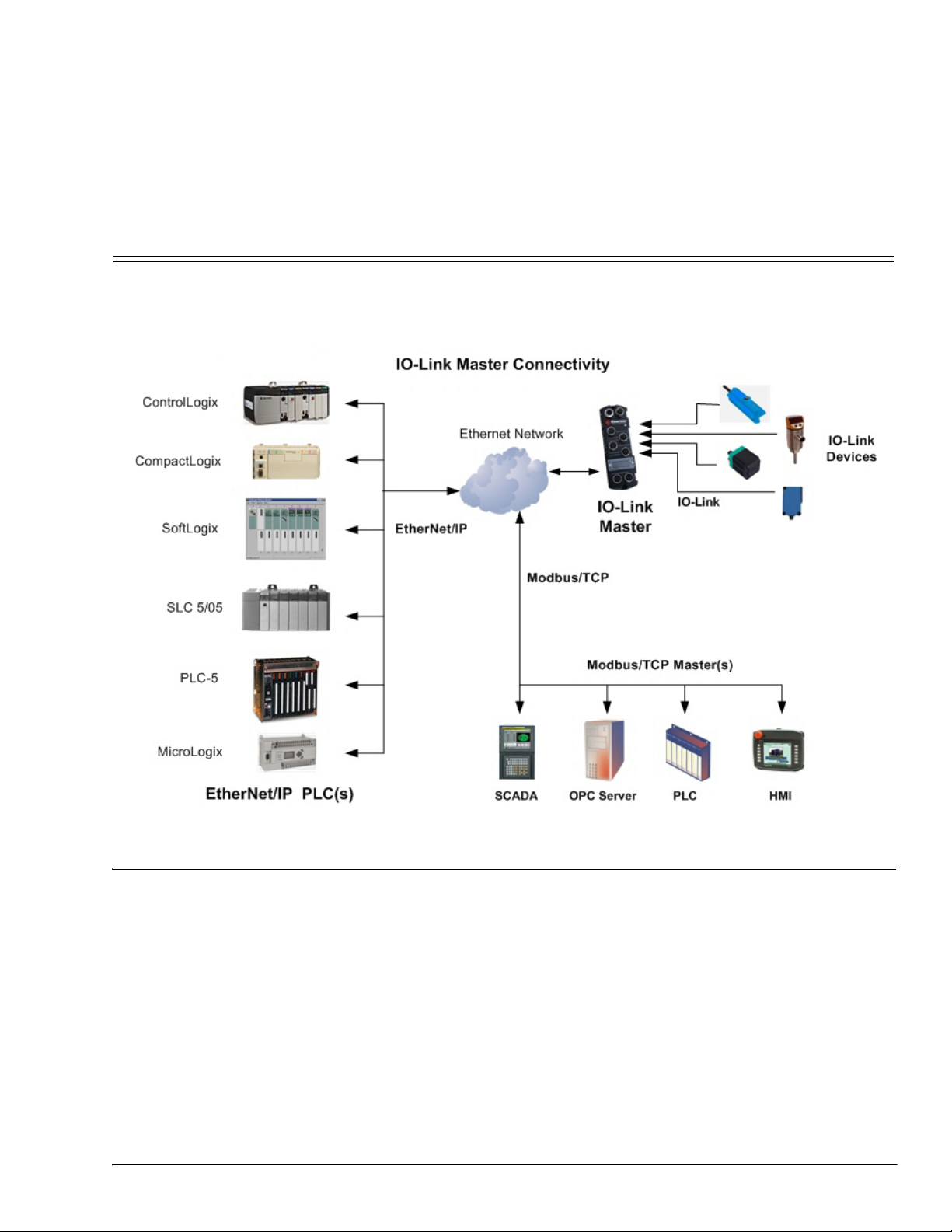
This section is intended to describe the EtherNet/IP and Modbus/TCP interfaces provided by the IO-Link
Master.
These interfaces provide the ability to retrieve port and device status information, input and output process
data and access to IO-Link device ISDU (SPDU) data blocks.
1.1.1. Functionality Summary
The EtherNet/IP interface consists of:
• Input Process Data blocks that include:
- Port communication status
- PDI valid status
- Auxiliary Input status (pin 2 of IO-Link connector)
- The active event code (zero if no active event)
- The input process data received from the port. This may be
• IO-Link mode: IO-Link device input process data
• I/O Input mode: Input bit status
• I/O Output mode: Output bit status (configurable option)
IO-Link Master EtherNet/IP Reference Manual: 2000589 Rev. A Chapter 1. EtherNet/IP Interface - 7
Page 8

Data Type Definitions
• Output Process Data blocks that include:
- The active event code to clear ((configurable option)
- The output process data to be sent to the port. This may be
• IO-Link mode: IO-Link device output process data
• I/O Output mode: Output bit status
• ISDU (ISDU) interface:
- Provides single and nested batch read/write capabilities
- Requires use of MSG instructions
- Provides both blocking and non-blocking message capabilities
• Blocking message responses are not returned until all the ISDU command(s) have completed.
• Non-blocking messages return immediately. The PLC must then request the ISDU command(s)
response status until a valid response is returned.
• Web based configuration and diagnostic pages:
- IO-Link interface configuration and diagnostics
- EtherNet/IP interface configuration and diagnostics
• EtherNet/IP interface support for ControlLogix, SLC, MicroLogix, and PLC-5 PLC families.
• Modbus/TCP slave interface.
• Example PLC programs to aid the PLC programmer.
1.1.2. Data Type Definitions
The following data type definitions apply.
BOOL Boolean; TRUE if = 1; False if = 0
USINT Unsigned Short Integer (8 bit)
CHAR Character (8 bit)
SINT Short Integer (8 bit)
UINT Unsigned Integer (16 bit)
INT Signed Integer (16 bit)
UDINT Unsigned Double Integer (32 bit)
DINT Signed Double Integer (32 bit)
STRING Character String (1 byte per character)
BYTE Bit String (8 bit)
WORD Bit String (16 bits)
DWORD Bit String (32 bits)
Data Type Definitions
8 - Chapter 1. EtherNet/IP Interface IO-Link Master EtherNet/IP Reference Manual: 2000589 Rev. A
Page 9

1.1.3. Terms and Definitions
This section uses the following terms and definitions.
Term Definition
Otherwise called implicit messaging, is a method of communication
between EtherNet/IP controllers and devices that:
Class 1
Class 3
EtherNet/IP
Ethernet TCP/IP
Ethernet UDP/IP
IO-Link Master
Multicast
Point-to-Point
PDI data
(Process Data
Input)
PDO data
(Process Data
Output)
ISDU
ISDU
Class 1
• Uses Ethernet UDP messages.
• Is cyclic in nature. Input and/or output data is exchanged between
the controllers and devices at regular time intervals.
Otherwise called explicit messaging, is a method of communication
between EtherNet/IP controllers and devices that:
• Uses Ethernet TCP/IP messages.
• By itself is not cyclic in nature. The controller and devices must send
individual messages to each other.
An Ethernet based industrial communication protocol utilized to
communicate between controllers, often times PLCS, and devices.
Standard Ethernet communications protocol utilizing socket
communication interfaces that guarantees delivery to the intended
device.
Standard Ethernet communications protocol utilizing socket
communication interfaces that does not guarantee delivery. The data
may or may get to the intended device.
IO-Link gateway that provides communication between IO-Link devices
and Ethernet protocols such as EtherNet/IP and Modbus/TCP.
Multicast addressing involves Ethernet devices sending messages to each
other using a multicast address. Multicast addressing:
• Uses a specified IP address range designated for multicast
communication.
• Allows either one or multiple devices to receive the same messages.
Point-to-Point, otherwise called unicast, addressing involves Ethernet
devices sending messages directly to each other using their own IP
addresses. Messages are sent to only one device.
Process data received from an IO-Link device or I/O interface that can be
provided to external controllers such as PLCs, HMIs, SCADA, and OPC
Servers.
Process data received from external controllers such as PLCs, HMIs,
SCADA, and OPC Servers and sent to an IO-Link device or I/O interface.
Note: IO-Link devices may or may not support PDO data.
Service Process Data Unit. Otherwise called ISDU, refers to the Service
Data units on IO-Link devices that are used for information, status and
configuration settings.
Indexed Service Data Unit. Otherwise called ISDU, refers to the Service
Data units on IO-Link devices that are used for information, status and
configuration settings.
Otherwise called implicit messaging, is a method of communication
between EtherNet/IP controllers and devices that:
• Uses Ethernet UDP messages.
• Is cyclic in nature. Input and/or output data is exchanged between
the controllers and devices at regular time intervals.
Terms and Definitions
IO-Link Master EtherNet/IP Reference Manual: 2000589 Rev. A Chapter 1. EtherNet/IP Interface - 9
Page 10
Data Transfer Methods
1.2. Data Transfer Methods
The IO-Link Master provides a selection of process data transfer methods and a number of options to
customize the process data handling.
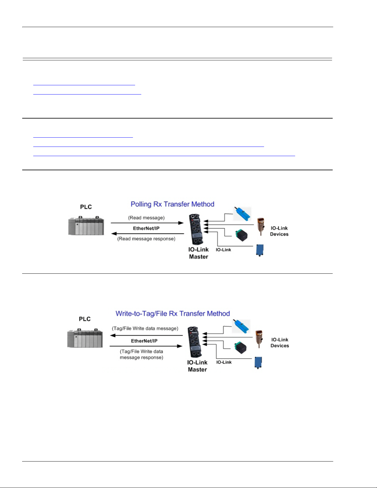
• 1.2.1. Receive Process Data Methods
• 1.2.2. Transmit Process Data Methods on Page 11
1.2.1. Receive Process Data Methods
The IO-Link Master supports the following receive process data methods:
• 1.2.1.1. Polling-PLC Requests Data
• 1.2.1.2. Write-to-Tag/File-IO-Link Master Writes Data Directly Into PLC Memory
• 1.2.1.3. Class 1 Connection (Input Only)-PLC and IO-Link Master Utilize an I/O Connection
1.2.1.1. Polling-PLC Requests Data
Also called Slave-Mode for some industrial protocols, the polling method requires the controller to request
data from the IO-Link Master via messages. The IO-Link Master does not respond until it receives a request
for data.
1.2.1.2. Write-to-Tag/File-IO-Link Master Writes Data Directly Into PLC Memory
Also called Master-Mode for some industrial protocols, the Write-to-Tag/File method requires the IO-Link
Master to send messages that write data directly into a tag or file on the PLC. The IO-Link Master sends
changed data to the PLC immediately and, optionally, can be configured to also send “heartbeat” update
messages at a regular time interval.
10 - Chapter 1. EtherNet/IP Interface IO-Link Master EtherNet/IP Reference Manual: 2000589 Rev. A
Page 11
Class 1 Connection (Input Only)-PLC and IO-Link Master Utilize an I/O Connection
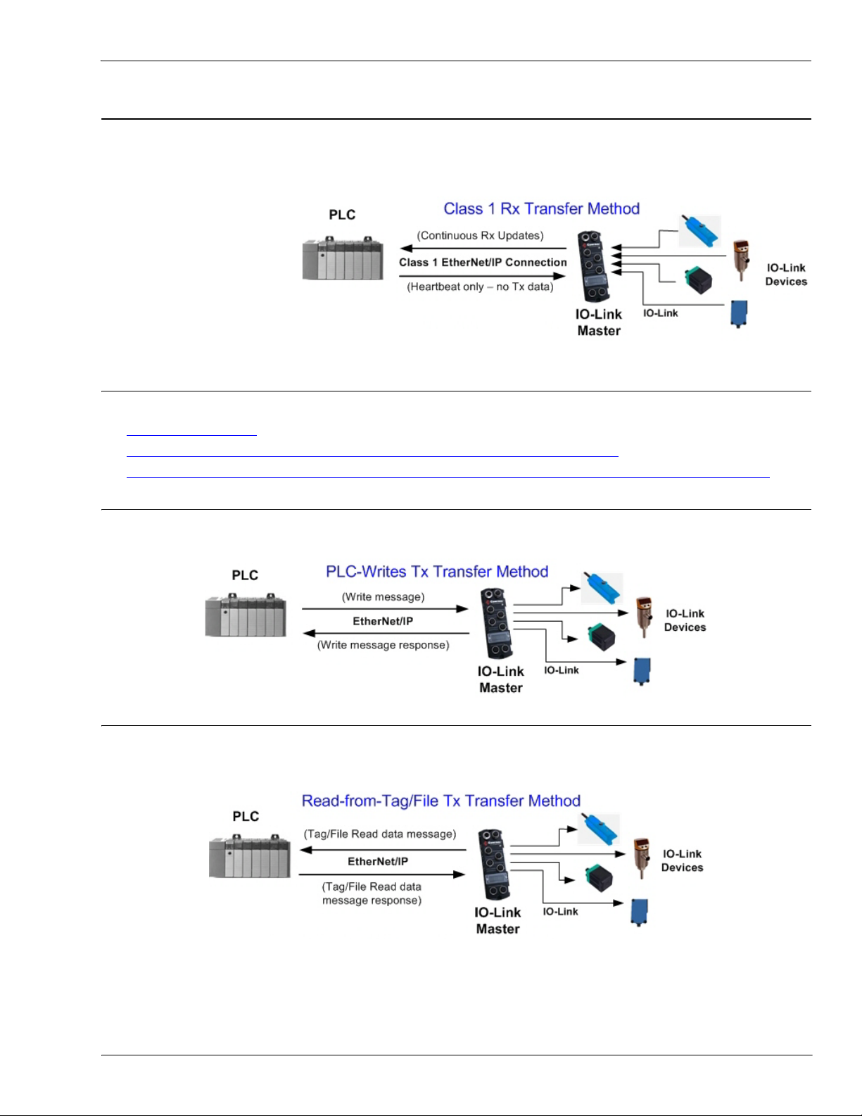
1.2.1.3. Class 1 Connection (Input Only)-PLC and IO-Link Master Utilize an I/O Connection
Also called I/O Mode for some industrial protocols, the Class 1 connection method requires the IO-Link
Master and PLC to connect to each via an I/O connection. For EtherNet/IP, a connection over UDP must first
be created. Once the connection is established, the IO-Link Master continually sends input data to the PLC at
a PLC configurable rate.
1.2.2. Transmit Process Data Methods
The IO-Link Master supports the following transmit process data methods:
• 1.2.2.1. PLC-Writes
• 1.2.2.2. Read-from-Tag/File-IO-Link Master Reads Data from PLC Memory
• 1.2.2.3. Class 1 Connection (Input and Output)-PLC and IO-Link Master Utilize an I/O Connection
1.2.2.1. PLC-Writes
Also called Slave-Mode for some industrial protocols, the PLC-Writes method requires the PLC to send data
to the IO-Link Master via write messages.
1.2.2.2. Read-from-Tag/File-IO-Link Master Reads Data from PLC Memory
Also called Master-Mode for some industrial protocols, the Read-from-Tag/File method requires the IO-Link
Master to read data from a tag or file on the PLC. In this method, the IO-Link Master requests data from the
PLC at configurable time intervals.
IO-Link Master EtherNet/IP Reference Manual: 2000589 Rev. A Chapter 1. EtherNet/IP Interface - 11
Page 12
Class 1 Connection (Input and Output)-PLC and IO-Link Master Utilize an I/O Connection
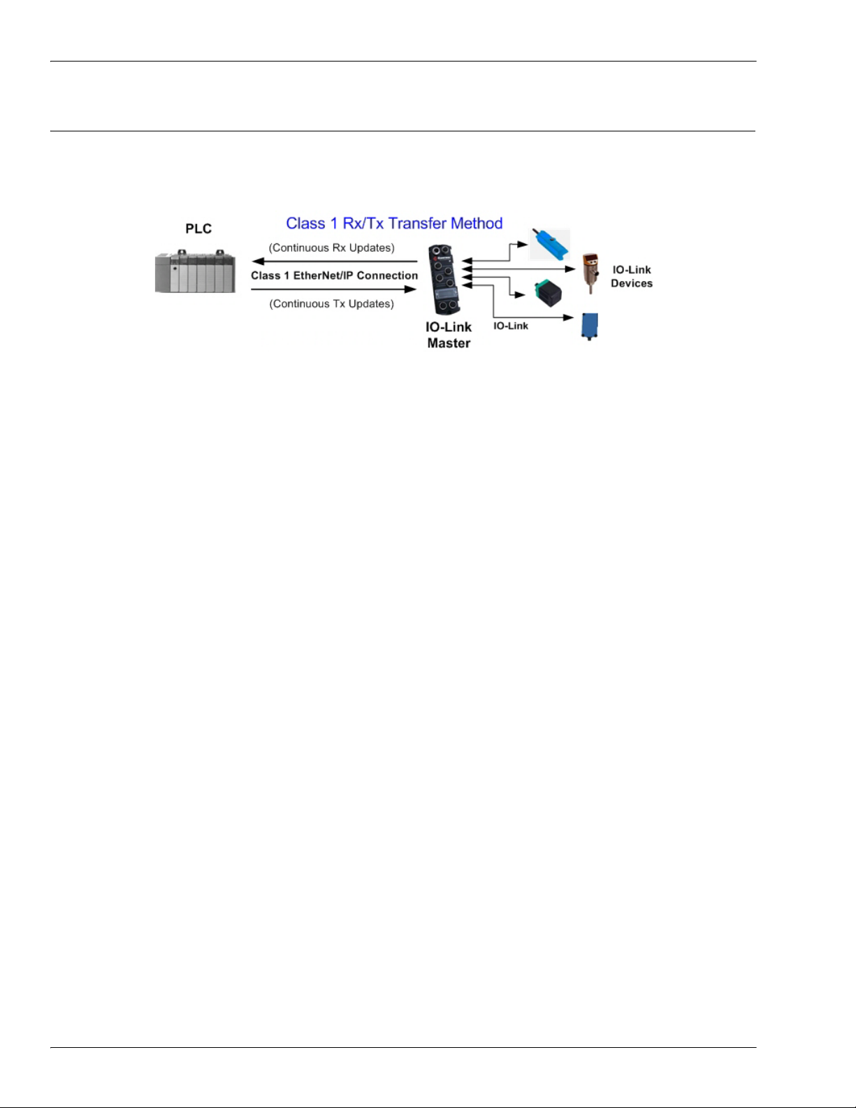
1.2.2.3. Class 1 Connection (Input and Output)-PLC and IO-Link Master Utilize an I/O Connection
Also called I/O Mode for some industrial protocols, the Class 1 connection method requires the IO-Link
Master and PLC to connect to each via an I/O connection. For EtherNet/IP, a connection over UDP must first
be created. Once the connection is established, the PLC and IO-Link Master continually exchange data at a
configurable rate.
12 - Chapter 1. EtherNet/IP Interface IO-Link Master EtherNet/IP Reference Manual: 2000589 Rev. A
Page 13

Process Data Block Descriptions
1.3. Process Data Block Descriptions
This subsection discusses the following:
• 1.3.1. Input Process Data Block Description
• 1.3.2. Output Process Data Block Description on Page 15
1.3.1. Input Process Data Block Description
The Input Process Data Block format is dependent on the configured PDI Data Format. The following tables
describe the Input Process Data Block in the possible formats.
Parameter Name Data Type Description
The status of the IO-Link device.
Bit 0 (0x01):
0 = IO-Link port communication initialization process is inactive
1 = IO-Link port communication initialization process is active
Bit 1 (0x02):
0 = IO-Link port communication is not operational
1 = IO-Link port communication is operational
Bit 2 (0x04):
0 = IO-Link input process data is not valid.
1 = IO-Link input process data is valid.
Bit 3 (0x08):
0= No fault detected
Port Status BYTE
1= Fault detected
• A minor communication fault is indicated by the Operational
status bit being set to 1. A minor communication fault results
from:
- A temporary loss of communication to the IO-Link device.
- A recoverable IO-Link Master software or hardware fault.
• A major communication fault is indicated by the Operational
bit being set to 0.
- An unrecoverable loss of communication to the IO-Link
device.
- An unrecoverable IO-Link Master software or hardware
fault.
Bits 4-7: Reserved (0)
Auxiliary I/O:
Bit 0: The status of the Pin 2 auxiliary bit.
Auxiliary I/O BYTE
Event Code INT 16-bit event code received from the IO-Link device.
PDI Data
Default Length = 32
bytes
IO-Link Master EtherNet/IP Reference Manual: 2000589 Rev. A Chapter 1. EtherNet/IP Interface - 13
Array of up
to 32
BYTEs
0 = off
1 = on
Bits 1-7: Reserved (0)
The PDI data as received from the IO-Link device. May contain from 0
to 32 bytes of PDI data. The definition of the PDI data is device
dependent.
Note: Length is configurable using the web page interface.
Page 14

Input Process Data Block-8 Bit Data Format
1.3.1.1. Input Process Data Block-8 Bit Data Format
The following table provides detailed information about the Input Process Data Block-8 Bit data format.
Byte Bit 7 Bit 0
0Port Status
1 Auxiliary I/O
2Event Code LSB
3Event Code MSB
4 PDI Data Byte 0
5 PDI Data Byte 1
.. ..
.. ..
N+3 PDI Data Byte (N-1)
1.3.1.2. Input Process Data Block-16 Bit Data Format
The following table provides detailed information about the Input Process Data Block-16 data format.
Word Bit 15 Bit 8 Bit 7 Bit 0
0 Port Status Auxiliary I/O
1Event Code
2 PDI Data Word 0
3 PDI Data Word 1
.. ..
.. ..
N+1 PDI Data Word (N-1)
1.3.1.3. Input Process Data Block-32 Bit Data Format
The following table provides detailed information about the Input Process Data Block-32 Bit data format.
Long
Word
Bit 31 Bit 24 Bit 23 Bit 16 Bit 15 Bit 0
0 Port Status Auxiliary I/O Event Code
2 PDI Data Long Word 0
3 PDI Data Long Word 1
.. ..
N PDI Data Long Word (N-1)
14 - Chapter 1. EtherNet/IP Interface IO-Link Master EtherNet/IP Reference Manual: 2000589 Rev. A
Page 15

1.3.2. Output Process Data Block Description
The contents of the Output Process Data Block are configurable.
Parameter Name Data Description
Output Process Data Block Description
Event to Clear
(Configurable option)
INT
If included, allows clearing of 16-bit event code received in
the PDI data block via the PDU data block.
Default: Not included
The PDO data written to the IO-Link device. May contain
PDO Data
Default Length = 32 bytes
Array of up
to 32 BYTEs
from 0 to 32 bytes of PDO data. The definition and length
of the PDO data is device dependent.
Note: Length is configurable via web page interface.
1.3.2.1. Output Process Data Block-8 Bit (SINT) Data Format
With the Include Event to Clear option selected:
Byte Bit 7 Bit 0
0 Event Code LSB
1 Event Code MSB
2 PDO Data Byte 0
3 PDO Data Byte 1
.. ..
.. ..
N+1 PDO Data Byte (N-1)
Without the Event to Clear option selected:
Byte Bit 7 Bit 0
0 PDO Data Byte 0
1 PDO Data Byte 1
.. ..
.. ..
N-1 PDO Data Byte (N-1)
1.3.2.2. Output Process Data Block-16 Bit (INT) Data Format
With the Include Event to Clear option selected:
Word Bit 15 Bit 0
0 Event Code
1 PDO Data Word 0
2 PDO Data Word 1
.. ..
.. ..
N PDO Data Word (N-1)
IO-Link Master EtherNet/IP Reference Manual: 2000589 Rev. A Chapter 1. EtherNet/IP Interface - 15
Page 16

Output Process Data Block-32 Bit (DINT) Data Format
Without the Event to Clear option selected:
Word Bit 15 Bit 0
0 PDO Data Word 0
1 PDO Data Word 1
.. ..
.. ..
N-1 PDO Data Word (N-1)
1.3.2.3. Output Process Data Block-32 Bit (DINT) Data Format
With the Include Event to Clear option selected:
Long Word Bit 31 Bit 16 Bit 15 Bit 0
0 0 Event Code
1 PDO Data Long Word 0
2 PDO Data Long Word 1
.. ..
.. ..
N - 1 PDO Data Long Word (N-1)
Without the Event to Clear option selected:
Long Word Bit 31 Bit 0
0 PDO Data Long Word 0
1 PDO Data Long Word 1
.. ..
.. ..
N - 1 PDO Data Long Word (N-1)
16 - Chapter 1. EtherNet/IP Interface IO-Link Master EtherNet/IP Reference Manual: 2000589 Rev. A
Page 17

Chapter 2. Functionality Descriptions
This appendix discusses the following:
• 2.1. Event Handling
• 2.2. ISDU Handling on Page 21
2.1. Event Handling
The IO-Link Master event handling is designed to provide real-time updates of event codes received directly
from the IO-Link device. The IO-Link event code:
• Is included in the second 16-bit word of the Input Process Data (PDI) block.
- An active event is indicated by a non-zero value.
- Inactive or no event is indicated by a zero value.
• Two methods are provided to clear an event:
- Enable the Clear Event After Hold Time option.
• The IO-Link Master keeps, or holds, the active event code in the PDI block until the configured Active
Event Hold Time has passed.
• The IO-Link Master then clears the event code in the PDI block and waits until the Clear Event Hold
Time has passed before including another event code in the PDI block.
- Enable the Clear Event In PDO Block option.
• The IO-Link Master monitors the PDO block received from the PLC.
• The IO-Link Master expects the first entry of the PDO block to indicate an event code to be cleared.
• If there is an active event code in the PDI block and the PDO block both contain the same event
code, the event code is cleared in the PDI block.
• The IO-Link Master then clears event code in the PDI block and waits until the Clear Event Hold
Time has passed before including another event code in the PDI block.
• The two methods can be used separately or together to control clearing of events.
The next subsections illustrate the event clearing process for the various event configurations.
IO-Link Master EtherNet/IP Reference Manual: 2000589 Rev. A Chapter 2. Functionality Descriptions - 17
Page 18
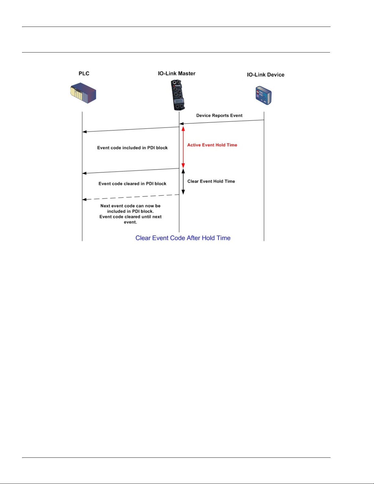
Clear Event After Hold Time Process
2.1.1. Clear Event After Hold Time Process
This illustrates clearing the event after the hold time process.
18 - Chapter 2. Functionality Descriptions IO-Link Master EtherNet/IP Reference Manual: 2000589 Rev. A
Page 19
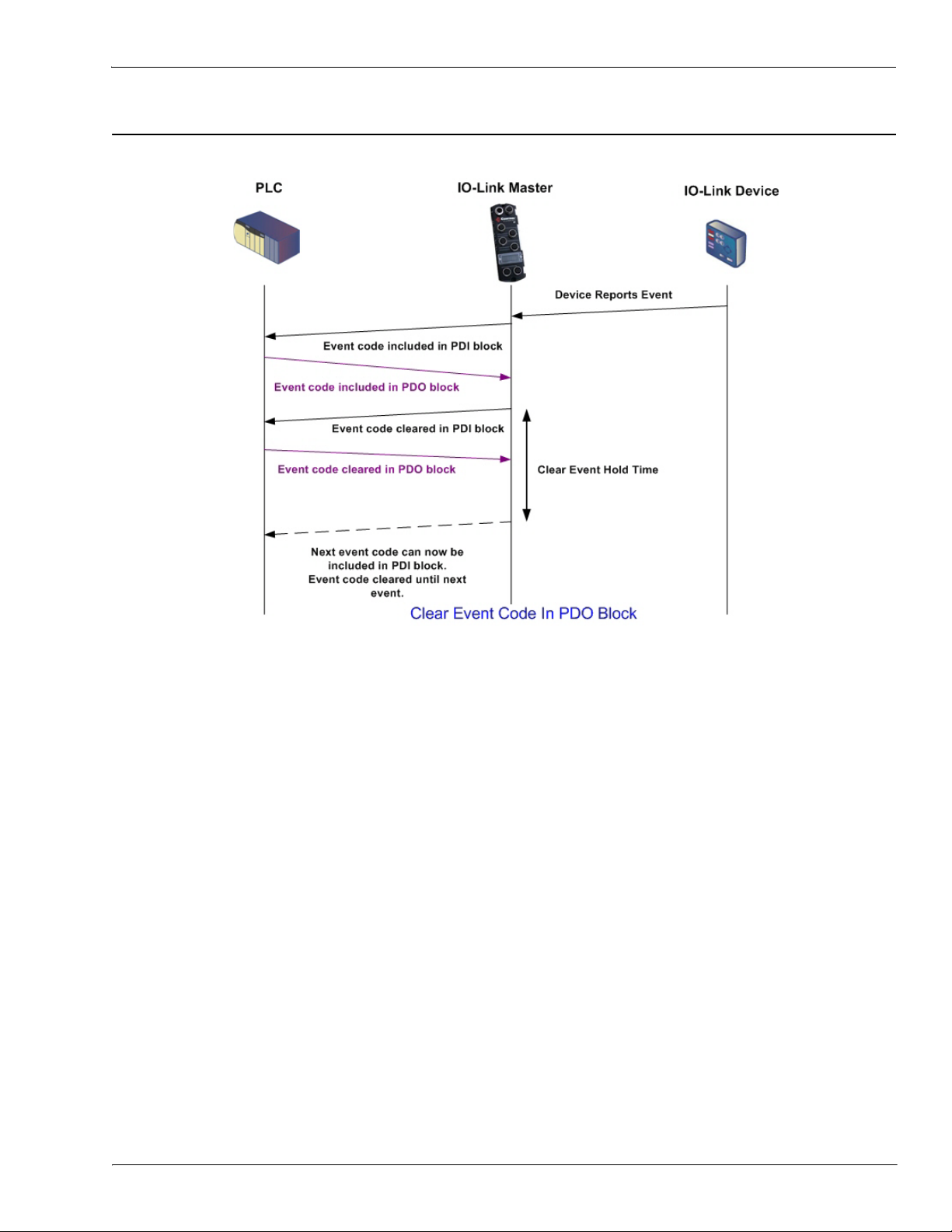
2.1.2. Clear Event in PDO Block Process
This illustrates clearing the event in the PDO block process.
Clear Event in PDO Block Process
IO-Link Master EtherNet/IP Reference Manual: 2000589 Rev. A Chapter 2. Functionality Descriptions - 19
Page 20
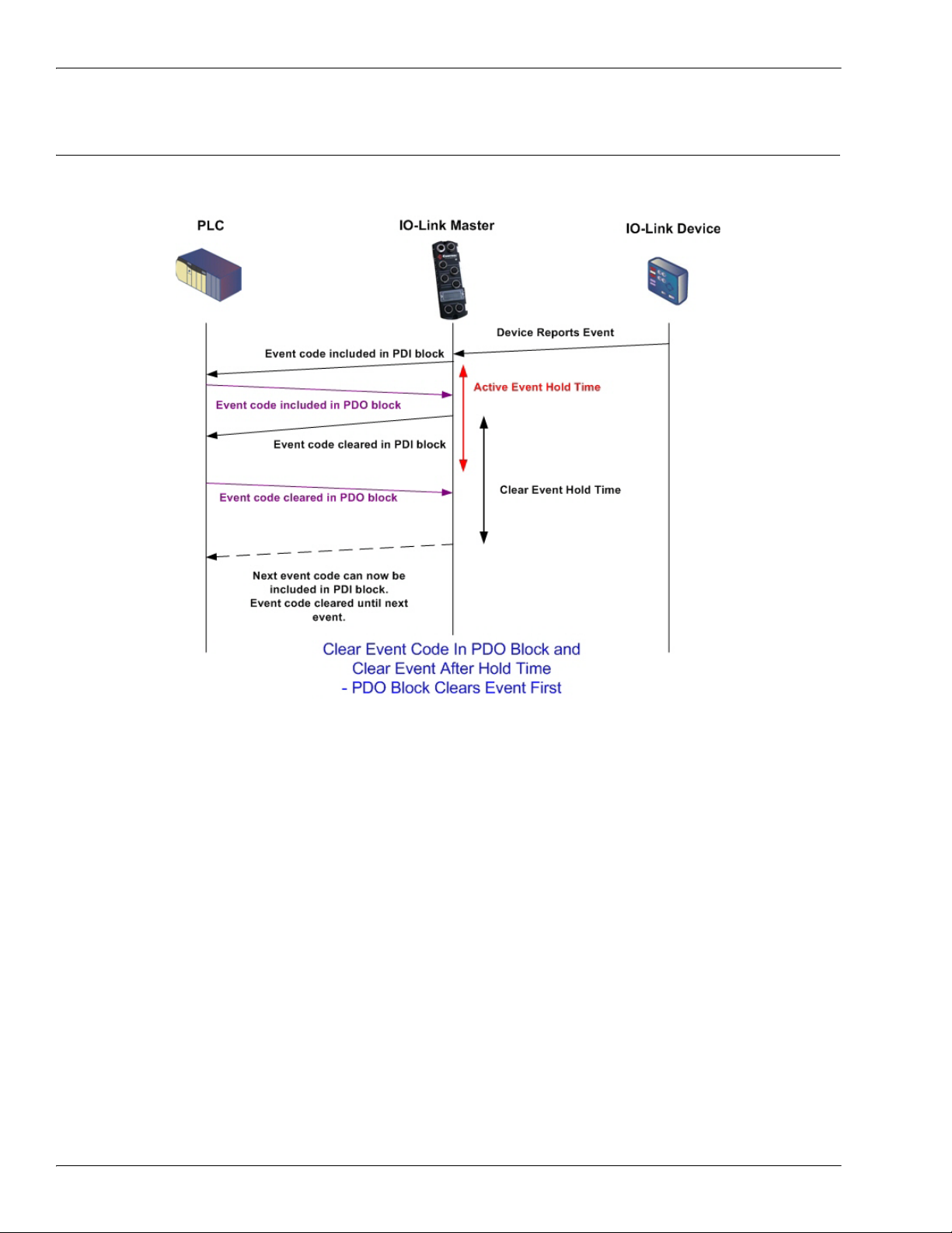
Clear Event Code in PDO Block and Clear Event After Hold Time Process-PDO Block First
2.1.3. Clear Event Code in PDO Block and Clear Event After Hold Time ProcessPDO Block First
This illustrates clearing the event code in the PDO block and clearing the event after the hold time process
with the PDO block first.
20 - Chapter 2. Functionality Descriptions IO-Link Master EtherNet/IP Reference Manual: 2000589 Rev. A
Page 21
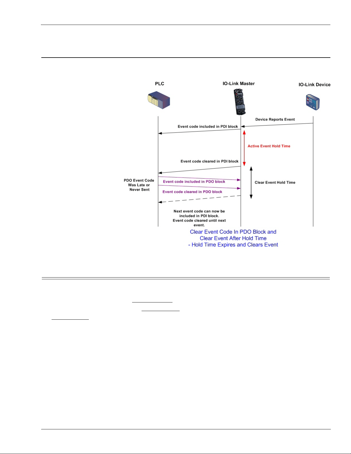
Clear Event Code in PDO Block and Clear Event After Hold Time Process-Hold Time Expires
2.1.4. Clear Event Code in PDO Block and Clear Event After Hold Time ProcessHold Time Expires
This illustrates clearing the event code in the PDO block and clearing the event after the hold time process
with the hold time expired.
2.2. ISDU Handling
The IO-Link Master provides a very flexible ISDU interface that is used by all supported industrial protocols.
The ISDU interface contains the following:
•An ISDU request may contain one or multiple individual ISDU read and/or write commands.
• Individual ISDU command based byte swapping capabilities.
• Variable sized command structures to allow access to wide range of ISDU block sizes.
• A single ISDU request may contain as many ISDU read and/or write commands as allowed by the
industrial protocol payload. For example, if an industrial protocol provides up to 500 byte read/write
payloads, then an ISDU request may contain multiple commands of various lengths that can total up to
500 bytes in length.
• For the ControlLogix family of EtherNet/IP PLCs, both blocking and non-blocking ISDU request methods
are provided.
- The IO-Link Master implements blocking ISDU requests by not responding to an ISDU request
message until all commands have been processed.
- The IO-Link Master implements non-blocking ISDU requests by:
• Responding to an ISDU request message immediately after receiving and verifying the ISDU
request.
• Requiring the PLC to monitor the ISDU request status with read messages. The IO-Link Master
will not return a completed status until all of the ISDU commands have been processed.
IO-Link Master EtherNet/IP Reference Manual: 2000589 Rev. A Chapter 2. Functionality Descriptions - 21
Page 22
ISDU Request/Response Structure
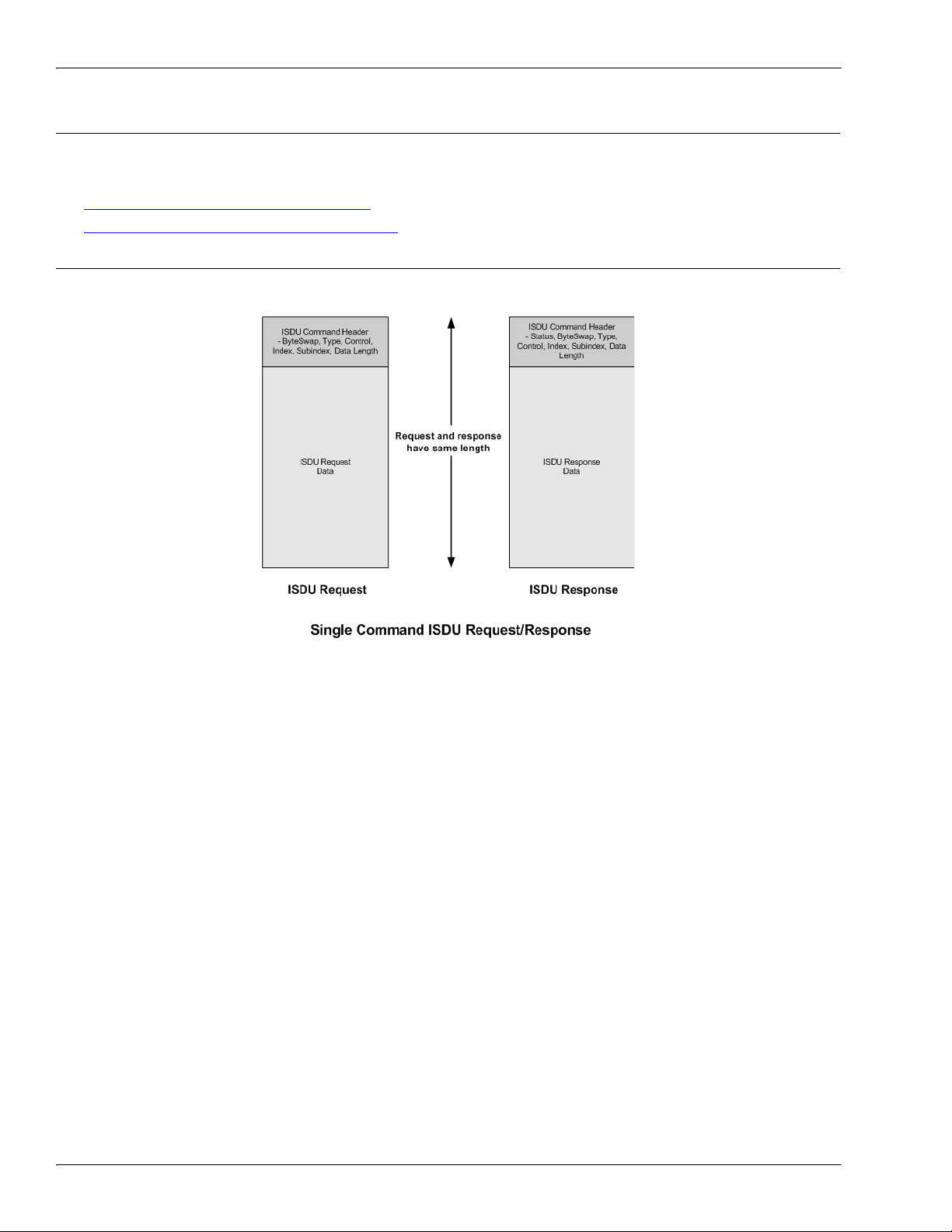
2.2.1. ISDU Request/Response Structure
ISDU requests may contain a single command or multiple, nested commands. This subsection discusses the
following:
• 2.2.1.1. Single ISDU Command Request on Page 22
• 2.2.1.2. Multiple ISDU Command Structure on Page 23
2.2.1.1. Single ISDU Command Request
This illustrates a single ISDU command request.
22 - Chapter 2. Functionality Descriptions IO-Link Master EtherNet/IP Reference Manual: 2000589 Rev. A
Page 23
Multiple ISDU Command Structure
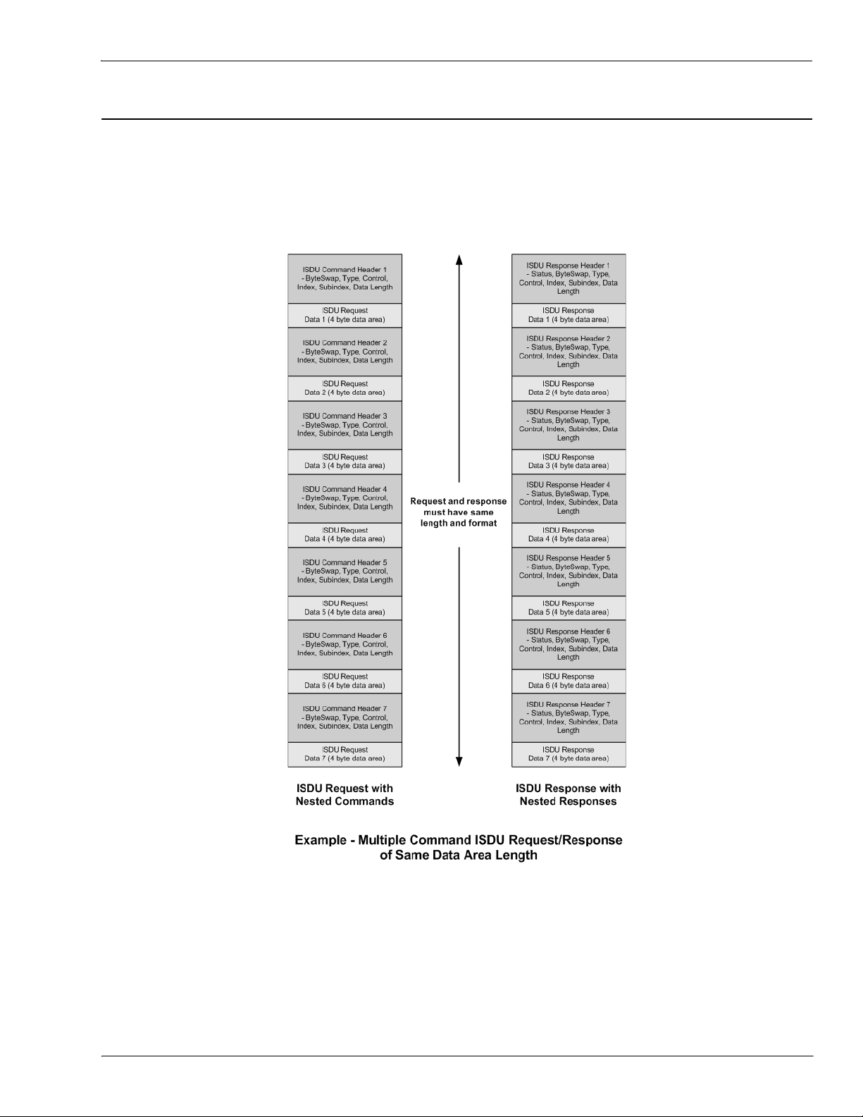
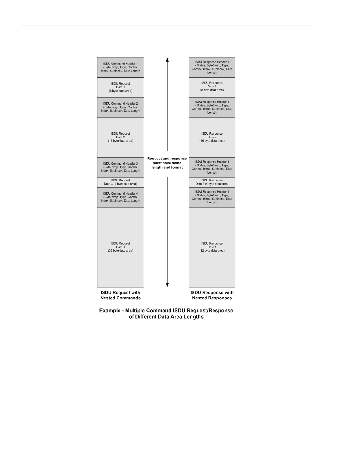
2.2.1.2. Multiple ISDU Command Structure
ISDU requests with multiple commands may consist of commands of the same data size or commands with
different data sizes. The following are two examples of multiple ISDU commands.
• ISDU commands of same data size (Page 23)
• ISDU commands of different data sizes (Page 24)
Multiple Command ISDU Request/Response of Same Data Area Length
IO-Link Master EtherNet/IP Reference Manual: 2000589 Rev. A Chapter 2. Functionality Descriptions - 23
Page 24
Multiple ISDU Command Structure
Multiple Command ISDU Request/Response of Different Data Lengths
24 - Chapter 2. Functionality Descriptions IO-Link Master EtherNet/IP Reference Manual: 2000589 Rev. A
Page 25

ISDU Request Message Format-From PLC to IO-Link Master
2.2.2. ISDU Request Message Format-From PLC to IO-Link Master
Write and read ISDU commands have the same message data format. Each ISDU request message is
comprised of one or more commands. The command(s) can consist of either a series of nested commands or a
single read command.
Note: A list of nested ISDU commands is terminated with either a control field of 0, (single/last operation), or
the end of the message data.
2.2.2.1. Standard ISDU Request Command Format
This table displays a standard ISDU request command format with ControlLogix PLCs.
Name Data Type Parameter Descriptions
Bits 0-3:
0= No byte swapping.
Byte Swapping USINT
RdWrControlType USINT
Index UINT The parameter address of the data object in the IO-Link device.
Subindex UINT
Datalength UINT
Array of
Data
USINTs,
UINTs, or
UDINTs.
1= 16-bit (INT) byte swapping of ISDU data.
2= 32-bit (DINT) byte swapping of ISDU data.
Bits 4-7:
Set to zero. Unused.
Provides the control and type of ISDU command.
Bits 0-3, Type Field:
0 = NOP (No operation)
1 = Read operation
2 = Write operation
3 = Read/Write “OR”
4 = Read/Write “AND”
Bits 4-7, Control Field:
0 = Single/Last Operation (length can vary from to 1 to 232)
1 = Nested batch command – fixed 4 byte data area
2 = Nested batch command – fixed 8 byte data area
3 = Nested batch command – fixed 16 byte data area
4 = Nested batch command – fixed 32 byte data area
5 = Nested batch command – fixed 64 byte data area
6 = Nested batch command – fixed 128 byte data area
7 = Nested batch command – fixed 232 byte data area
The data element address of a structured parameter of the data
object in the IO-Link device.
Length of data to read or write.
For nested batch commands, the data length can vary from 1 to
the fixed data area size.
Size of array is determined by the Control field in
RdWrControlType.
Note: Data is valid only for write commands.
IO-Link Master EtherNet/IP Reference Manual: 2000589 Rev. A Chapter 2. Functionality Descriptions - 25
Page 26

Integer (16-Bit Word) ISDU Request Command Format
2.2.2.2. Integer (16-Bit Word) ISDU Request Command Format
This table shows an integer (16 bit word) ISDU request command format with a SLC, MicroLogix, PLC-5, or
Modbus/TCP.
Name Data Type Parameter Description
Provides the control, type and byte swapping of ISDU command
Bits 0-3, Type Field:
0 = NOP (No operation)
1 = Read operation
2 = Write operation
3 = Read/Write “OR”
4 = Read/Write “AND”
Bits 4-7, Control Field:
0 = Single/Last Operation (length can vary from to 1 to 232)
1 = Nested batch command – fixed 4 byte data area
Byte Swapping /
RdWrControlType
UINT
2 = Nested batch command – fixed 8 byte data area
3 = Nested batch command – fixed 16 byte data area
4 = Nested batch command – fixed 32 byte data area
5 = Nested batch command – fixed 64 byte data area
6 = Nested batch command – fixed 128 byte data area
7 = Nested batch command – fixed 232 byte data area
Bits 8-11:
0= No byte swapping.
1= 16-bit (INT) byte swapping of ISDU data.
2= 32-bit (DINT) byte swapping of ISDU data.
Bits 12-15:
Set to zero. Unused.
Index UINT The parameter address of the data object in the IO-Link device.
Subindex UINT
The data element address of a structured parameter of the data
object in the IO-Link device.
Length of data to read or write.
Datalength UINT
For nested batch commands, the data length can vary from 1 to the
fixed data area size.
Data
Array of
USINTs,
UINTs, or
UDINTs.
Size of array is determined by the Control field in
RdWrControlType.
Note: Data is valid only for write commands.
26 - Chapter 2. Functionality Descriptions IO-Link Master EtherNet/IP Reference Manual: 2000589 Rev. A
Page 27

ISDU Response Message Format
2.2.3. ISDU Response Message Format
The ISDU responses have the same data format as requests with the only exception being the returned
command status. Each ISDU response message is comprised of one or more responses to the single and/or
nested command(s) received in the request.
2.2.3.1. Standard ISDU Response Command Format
The following table show the standard ISDU response command format with ControlLogix PLCs.
Name Data Type Parameter Description
Indicates the byte alignment and status of the command response.
Byte swapping, bits 0-3:
0= No byte swapping.
1= 16-bit (INT) byte swapping of TX/RX ISDU data.
Status USINT
RdWrControlType USINT
Index UINT The parameter address of the data object in the IO-Link device.
Subindex UINT
Datalength UINT
Array of
Data
USINTs,
UINTs, or
UDINTs.
2= 32-bit (DINT) byte swapping of TX/RX ISDU data.
Status, bits 4-7:
0 = NOP (No operation)
1 = In process (Only valid for non-blocking requests)
2 = Success
3 = Failure: IO-Link device rejected the request.
4 = Timed out: IO-Link device did not respond
Provides the control and type of ISDU request
Bits 0-3, Type Field:
0 = NOP (No operation)
1 = Read operation
2 = Write operation
3 = Read/Write “OR”
4 = Read/Write “AND”
Bits 4-7, Control Field:
0 = Single/Last Operation (length can vary from to 1 to 232)
1 = Nested batch command – fixed 4 byte data area
2 = Nested batch command – fixed 8 byte data area
3 = Nested batch command – fixed 16 byte data area
4 = Nested batch command – fixed 32 byte data area
5 = Nested batch command – fixed 64 byte data area
6 = Nested batch command – fixed 128 byte data area
7 = Nested batch command – fixed 232 byte data area
The data element address of a structured parameter of the data
object in the IO-Link device.
Length of data that was read or written.
For nested batch commands, the data length can vary from 1 to
fixed data area size.
Data required for read commands. Optionally can return the data
of a write command.
The size of the array is determined by the Control field in the
RdWrControlType.
Note: Data field not required for single NOP commands.
IO-Link Master EtherNet/IP Reference Manual: 2000589 Rev. A Chapter 2. Functionality Descriptions - 27
Page 28

Integer (16-Bit Word) ISDU Response Command Format
2.2.3.2. Integer (16-Bit Word) ISDU Response Command Format
The following table shows an integer (16-bit word) ISDU response command format with SLC, MicroLogix,
PLC-5, or Modbus/TCP.
Name Data Type Parameter Descriptions
Indicates the control, type, byte swapping and status of the
ISDU command.
Bits 0-3, Type Field:
0 = NOP (No operation)
1 = Read operation
2 = Write operation
3 = Read/Write “OR”
4 = Read/Write “AND”
Bits 4-7, Control Field:
0 = Single/Last Operation (length can vary from to 1 to 232)
1 = Nested batch command – fixed 4 byte data area
2 = Nested batch command – fixed 8 byte data area
Status,
Byte-Swapping,
RdWrControlType
UINT
3 = Nested batch command – fixed 16 byte data area
4 = Nested batch command – fixed 32 byte data area
5 = Nested batch command – fixed 64 byte data area
6 = Nested batch command – fixed 128 byte data area
7 = Nested batch command – fixed 232 byte data area
Byte swapping, bits 8-11:
0= No byte swapping.
1= 16-bit (INT) byte swapping of TX/RX ISDU data.
2= 32-bit (DINT) byte swapping of TX/RX ISDU data.
Status, bits 12-15:
0 = NOP (No operation)
1 = In process (Only valid for non-blocking requests)
2 = Success
3 = Failure: IO-Link device rejected the request.
4 = Timed out: IO-Link device did not respond
Index UINT The parameter address of the data object in the IO-Link device
Subindex UINT
The data element address of a structured parameter of the data
object in the IO-Link device.
Length of data that was read or written.
Datalength UINT
For nested batch commands, the data length can vary from 1 to
fixed data area size.
Data returned for read commands. Contains the data of a write
command.
The size of the array is determined by the Control field in
RdWrControlType.
Data
Array of
USINTs,
UINTs, or
UDINTs
Note: Data field not required for single NOP commands.
28 - Chapter 2. Functionality Descriptions IO-Link Master EtherNet/IP Reference Manual: 2000589 Rev. A
Page 29
ISDU Blocking and Non-Blocking Methods
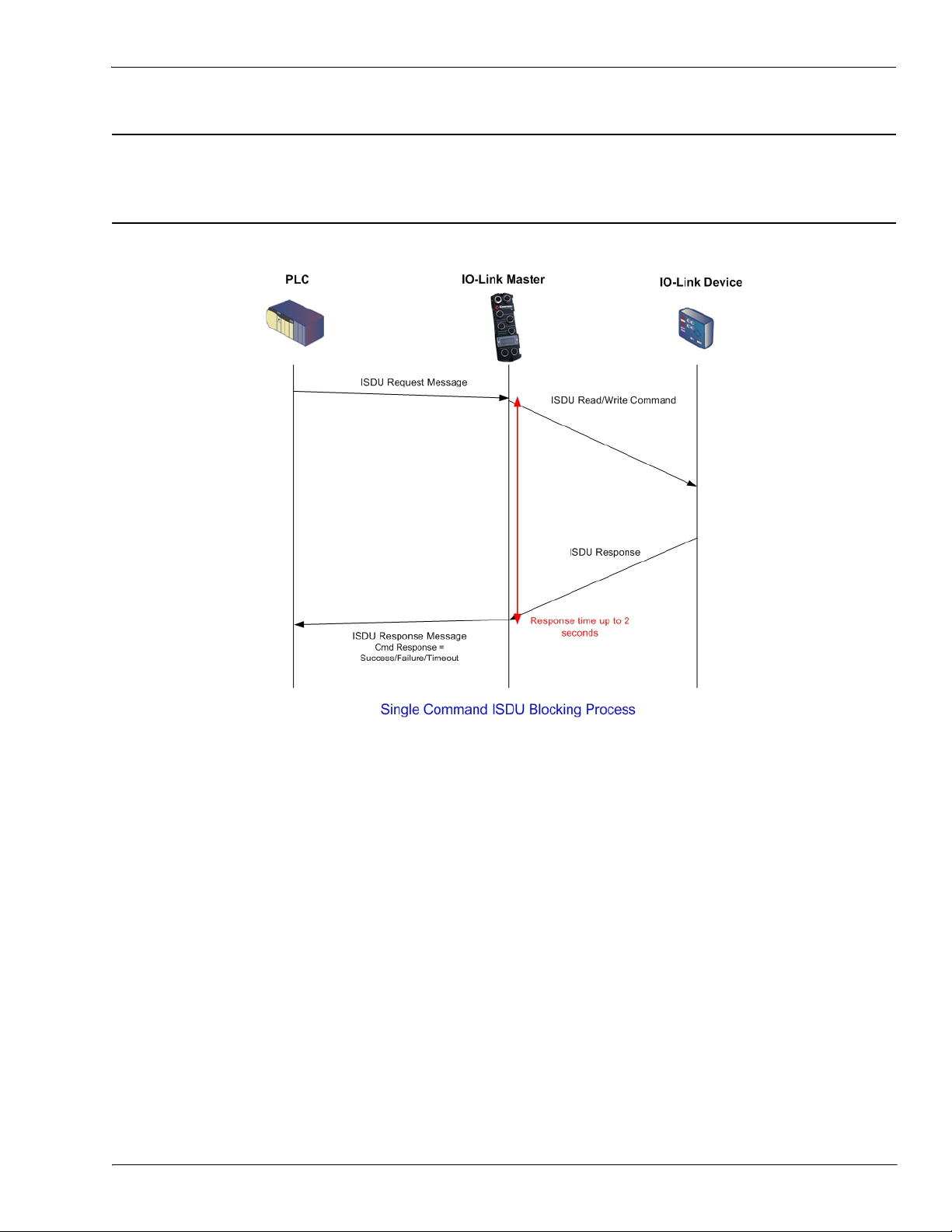
2.2.4. ISDU Blocking and Non-Blocking Methods
The IO-Link Master supports both blocking and non-blocking ISDU requests. The following diagrams
demonstrate how each mode works.
2.2.4.1. Single Command Blocking
The following illustrates the single command blocking method.
IO-Link Master EtherNet/IP Reference Manual: 2000589 Rev. A Chapter 2. Functionality Descriptions - 29
Page 30

Multiple Command Blocking
2.2.4.2. Multiple Command Blocking
This illustrates the multiple command blocking method.
30 - Chapter 2. Functionality Descriptions IO-Link Master EtherNet/IP Reference Manual: 2000589 Rev. A
Page 31

2.2.4.3. Single Command Non-Blocking
This illustrates the single command non-blocking method.
Single Command Non-Blocking
IO-Link Master EtherNet/IP Reference Manual: 2000589 Rev. A Chapter 2. Functionality Descriptions - 31
Page 32

Multiple Command Non-Blocking
2.2.4.4. Multiple Command Non-Blocking
This illustrates the multiple command non-blocking method.
32 - Chapter 2. Functionality Descriptions IO-Link Master EtherNet/IP Reference Manual: 2000589 Rev. A
Page 33

Chapter 3. EtherNet/IP CIP Object Definitions
The following are the vendor specific CIP Object definitions as supported in the IO-Link Master:
• 3.1. IO-Link Port Information Object Definition (71 hex)
• 3.2. PDI (Process Data Input) Transfer Object Definition (72 hex) on Page 41
• 3.3. PDO (Process Data Output) Transfer Object Definition (73 hex) on Page 42
• 3.4. ISDU Read/Write Object Definition (74 hex) on Page 43
The following are standard CIP Object Definitions that are supported in the IO-Link Master.
• 3.5. Identity Object (01hex, 1 instance) on Page 45
• 3.6. Message Router Object (02 hex) on Page 48
• 3.7. Connection Manager Object (06 hex) on Page 49
• 3.8. Port Object (F4 hex-1 instance) on Page 50
• 3.9. TCP Object (F5 hex-1 instance) on Page 52
• 3.10. Ethernet Link Object (F6 hex-1 instance) on Page 54
• 3.11. PCCC Object (67 hex-1 instance) on Page 56
3.1. IO-Link Port Information Object Definition (71 hex)
The IO-Link Device Information object defines the attributes by which the PLC can request standard device
information stored in the IO-Link device’s ISDU blocks.
IO-Link Master EtherNet/IP Reference Manual: 2000589 Rev. A Chapter 3. EtherNet/IP CIP Object Definitions - 33
Page 34

Class Attributes
3.1.1. Class Attributes
The following table shows the class attributes for IO-Link port information object definition (71 hex).
Attribute ID Name Data Type Data Value(s) Access Rule
1 Revision UINT 1 Get
2 Max Instance UINT 4 Get
4
3 Num Instances UINT
Note: Instance number determines the
IO-Link port.
Get
34 - Chapter 3. EtherNet/IP CIP Object Definitions IO-Link Master EtherNet/IP Reference Manual: 2000589 Rev. A
Page 35

Instance Attributes
3.1.2. Instance Attributes
The following table shows the instance attributes for IO-Link port information object definition (71 hex).
Attribute ID Name Data Type Data Value(s) Access Rule
1 Vendor Name Array of 64 SINTs 0-255 Get
2 Vendor Text Array of 64 SINTs 0-255 Get
3 Product Name Array of 64 SINTs 0-255 Get
4 Product Id Array of 64 SINTs 0-255 Get
5 Product Text Array of 64 SINTs 0-255 Get
6 Serial Number Array of 16 SINTs 0-255 Get
7 Hardware Revision Array of 64 SINTs 0-255 Get
8 Firmware Revision Array of 64 SINTs 0-255 Get
9 Device PDI Length INT 0-32 Get
10 Device PDO Length INT 0-32 Get
11 PDI Block Length INT 4-36 Get
12 PDO Block Length INT 0-36 Get
0-108 (8-bit format)
13 Input Assembly PDI Offset INT
14 Input Assembly PDO Offset INT
15 Output Assembly PDO Offset INT
16 Control Flags INT Bit settings Get
0-54(16-bit format)
0-27 (32-bit format)
16-246 (8-bit format)
8-123(16-bit format)
4-62 (32-bit format)
0-102 (8-bit format)
0-51 (16-bit format)
0-26 (32-bit format)
Get
Get
Get
IO-Link Master EtherNet/IP Reference Manual: 2000589 Rev. A Chapter 3. EtherNet/IP CIP Object Definitions - 35
Page 36

Common Services
3.1.3. Common Services
The following table shows the common services for IO-Link port information object definition (71 hex).
Service Code Implemented in Class Implemented in Instance Service Name
01 hex Yes Yes Get_Attributes_All
0E hex Ye s Ye s Get_Attribute_Single
36 - Chapter 3. EtherNet/IP CIP Object Definitions IO-Link Master EtherNet/IP Reference Manual: 2000589 Rev. A
Page 37

Instance Attribute Definitions
3.1.4. Instance Attribute Definitions
These attributes provide access to the standard ISDU information blocks on the IO-Link devices. These
ISDUs are read at IO-Link device initialization time and then provided once the IO-Link device is
operational.
IO-Link Master EtherNet/IP Reference Manual: 2000589 Rev. A Chapter 3. EtherNet/IP CIP Object Definitions - 37
Page 38

Attribute 1-Vendor Name
3.1.4.1. Attribute 1-Vendor Name
Data Attribute 1 - Vendor Name Description
64 ASCII
characters
Requested from ISDU block index 16, contains the Vendor Name
description of the IO-Link device.
3.1.4.2. Attribute 2-Vendor Text
Data Attribute 2 - Vendor Text Description
64 ASCII
characters
Requested from ISDU block index 17, contains the Vendor Text
description of the IO-Link device.
3.1.4.3. Attribute 3-Product Name
Data Attribute 3 - Product Name Description
64 ASCII
characters
Requested from ISDU block index 18, contains the Product Name
description of the IO-Link device.
3.1.4.4. Attribute 4-Product ID
Data Attribute 4 - Product ID Description
64 ASCII
characters
Requested from ISDU block index 19, contains the Product ID
description of the IO-Link device.
3.1.4.5. Attribute 5-Product Text
Data Attribute 5 - Product Text Description
64 ASCII
characters
Requested from ISDU block index 20, contains the Product Text
description of the IO-Link device.
3.1.4.6. Attribute 6-Serial Number
Data Attribute 6 - Serial Number Description
16 ASCII
characters
Requested from ISDU block index 21, contains the Vendor Specific
Serial Number of the IO-Link device.
3.1.4.7. Attribute 7-Hardware Revision
Data Attribute 7 - Hardware Revision Description
64 ASCII
characters
Requested from ISDU block index 22, contains the Hardware
Revision of the IO-Link device.
3.1.4.8. Attribute 8-Firmware Revision
Data Attribute 8 - Firmware Revision Description
64 ASCII
characters
Requested from ISDU block index 23, contains the Firmware
Revision of the IO-Link device.
38 - Chapter 3. EtherNet/IP CIP Object Definitions IO-Link Master EtherNet/IP Reference Manual: 2000589 Rev. A
Page 39

3.1.4.9. Attribute 9-Device PDI Length
Data Attribute 9 - Device PDI Length Description
Attribute 9-Device PDI Length
INT (0-32)
Requested from ISDU block index 0, sub-index 5. Contains the
number of PDI data bytes provided by the IO-Link device.
3.1.4.10. Attribute 10-Device PDO Length
Data Attribute 10 - Device PDO Length Description
INT
Requested from ISDU block index 0, sub-index 6. Contains the
number of PDO data bytes required by the IO-Link device.
3.1.4.11. Attribute 11-PDI Data Block Length
Data Attribute 11 - PDI Data Block Length Description
The configured PDI block length in units based on the configurable
INT
PDI data format (8-bit, 16-bit, 32-bit). This contains the PDI block
header, (port status, auxiliary bit, event code) status and the PDI
data.
3.1.4.12. Attribute 12-PDO Data Block Length
Data Attribute 12 - PDO Data Block Length Description
The configured PDO data block length in units based on the
INT
configurable PDO data format (8-bit, 16-bit, 32-bit). Depending on
the configuration, this may include both the returned event code and
the PDO data.
3.1.4.13. Attribute 13-Input Assembly PDI Offset
Data Attribute 13 - Input Assembly PDI Offset Description
Based from the start of the first Input Assembly instance, the PDI
data block’s offset for the corresponding port’s PDI data block.
INT
This index is based on the configurable PDI data format (8-bit, 16bit, 32-bit). To use this offset effectively, it is recommended to set IOLink Master PDI and PDO data as well as the Class 1 I/O connection
all to the same data format.
3.1.4.14. Attribute 14-Input Assembly PDO Offset
Data Attribute 14 - Input Assembly PDO Offset Description
Based from the start of the first Input Assembly instance, the PDO
data block’s offset for the corresponding port’s PDO data block.
INT
This index is based on the configurable PDO data format (8-bit, 16bit, 32-bit). To use this offset effectively, it is recommended to set IOLink Master PDI and PDO data as well as the Class 1 I/O connection
all to the same data format.
IO-Link Master EtherNet/IP Reference Manual: 2000589 Rev. A Chapter 3. EtherNet/IP CIP Object Definitions - 39
Page 40

Attribute 15-Output Assembly PDO Offset
3.1.4.15. Attribute 15-Output Assembly PDO Offset
Data Attribute 15 - Output Assembly PDO Offset Description
Based from the start of the first Output Assembly instance, the PDO
data block’s offset for the corresponding port’s PDO data block.
INT
This index is based on the configurable PDO data format (8-bit, 16bit, 32-bit). To use this offset effectively, it is recommended to set IOLink Master PDI and PDO data as well as the Class 1 I/O connection
all to the same data format.
3.1.4.16. Attribute 16-Control Flags
Data Attribute 16 - Control Flags Description
Bit 0 (01h):
1 = Indicates that the event code to clear is expected in the PDO
block
0 = Indicates that the event code to clear is not expected in the
PDO block. The PDO data block only contains PDO data.
Bit 1 (02h):
INT
(bitmapped
word)
1 = Indicates that the IO-Link device is SIO mode capable
0 = Indicates that the IO-Link device is not SIO mode capable
Bits 2 (04h)
1 = Indicates that Class 1 Rx (receive PDI block) is enabled
0 = Indicates that Class 1 Rx (receive PDI block) is disabled
Bit 3 (08h):
1 = Indicates that Class 1 Tx (transmit PDO) is enabled
0 = Indicates that Class 1 Tx (transmit PDO) is disabled
Bits 4-15: Reserved
40 - Chapter 3. EtherNet/IP CIP Object Definitions IO-Link Master EtherNet/IP Reference Manual: 2000589 Rev. A
Page 41

PDI (Process Data Input) Transfer Object Definition (72 hex)
3.2. PDI (Process Data Input) Transfer Object Definition (72 hex)
The PDI Transfer object defines the attributes by which the PLC can request the PDI data block from the IOLink Master.
3.2.1. Class Attributes
The following table displays Class Attributes for the PDI Transfer Object Definition (72 hex).
Attribute ID Name Data Type Data Value(s) Access Rule
1 Revision UINT 1 Get
2
3
3.2.2. Instance Attributes
The following table displays Instance Attributes for the PDI Transfer Object Definition (72 hex).
Max Instance UINT 1 Get
Num Instances UINT 1 Get
Attribute ID Name Data Type Length Data Values Access Rule
1 Port 1 PDI data block Array of BYTEs 4-36 bytes 0-255 Get
2
3
4
Port 2 PDI data block Array of BYTEs 4-36 bytes 0-255 Get
Port 3 PDI data block Array of BYTEs 4-36 bytes 0-255 Get
Port 4 PDI data block Array of BYTEs 4-36 bytes 0-255 Get
3.2.3. Common Services
The following table shows Common Services for the PDI Transfer Object Definition (72 hex).
Service Code Implemented in Class Implemented in Instance Service Name
01 hex Yes Yes Get_Attributes_All
0E hex Yes Yes Get_Attribute_Single
3.2.4. Instance Attribute Definitions - Attribute 1 to 4-PDI Data Blocks
These attributes provide access to the PDI data blocks.
• Get Attribute Single requests return the PDI data block for a specific port.
• Get Attribute All requests return all PDI data blocks from the IO-Link Master.
All PDI data is returned in the configured PDI format (8-bit, 16-bit or 32-bit). Refer to 3.2. PDI (Process Data
Input) Transfer Object Definition (72 hex) on Page 41 for a detailed explanation of the PDI data block.
IO-Link Master EtherNet/IP Reference Manual: 2000589 Rev. A Chapter 3. EtherNet/IP CIP Object Definitions - 41
Page 42

PDO (Process Data Output) Transfer Object Definition (73 hex)
3.3. PDO (Process Data Output) Transfer Object Definition (73 hex)
The PDO Transfer object defines the attributes by which the PLC can:
• Request the PDO data block from the IO-Link Master.
• Write PDO data block to the IO-Link Master.
3.3.1. Class Attributes
The following table displays the Class Attributes for the PDO Transfer Object Definition (73 hex).
Attribute ID Name Data Type Data Value Access Rule
1
2
3
3.3.2. Instance Attributes
Revision UINT 1 Get
Max Instance UINT 1 Get
Num Instances UINT 1 Get
The following table displays the Instance Attributes for the PDO Transfer Object Definition (73 hex).
Attribute ID Name Data Type Length Data Value Access Rule
1 Port 1 PDO data block Array of BYTEs 0-36 bytes 0-255 Get/Set
2 Port 2 PDO data block Array of BYTEs 0-36 bytes 0-255 Get/Set
3 Port 3 PDO data block Array of BYTEs 0-36 bytes 0-255 Get/Set
4 Port 4 PDO data block Array of BYTEs 0-36 bytes 0-255 Get/Set
3.3.3. Common Services
The following table displays the Common Services for the PDO Transfer Object Definition (73 hex).
Service Code Implemented in Class Implemented in Instance Service Name
01 hex Yes Yes Get_Attributes_All
0E hex Yes Yes Get_Attribute_Single
10 hex No Yes Set_Attribute_Single
02 hex No Yes Set_Attribute_All
3.3.4. Instance Attribute Definitions - Attribute 1 to 4-PDO Data Blocks
These attributes provide write access to the PDO data blocks.
• Get Attribute Single requests return the current PDO data block for a specific port.
• Get Attribute All requests return all current PDO data blocks from the IO-Link Master.
• Set Attribute Single allows writing the PDO data to one IO-Link port on the IO-Link Master.
• Set Attribute All messages allow writing of PDO data to all IO-Link ports on the IO-Link Master.
42 - Chapter 3. EtherNet/IP CIP Object Definitions IO-Link Master EtherNet/IP Reference Manual: 2000589 Rev. A
Page 43

ISDU Read/Write Object Definition (74 hex)
All PDO data is received and returned in the configured PDO format (8-bit, 16-bit or 32-bit). Refer to 3.3. PDO
(Process Data Output) Transfer Object Definition (73 hex) on Page 42 for a detailed explanation of the PDO
data block.
3.4. ISDU Read/Write Object Definition (74 hex)
The ISDU Read/Write object defines the attributes by which the PLC can:
• Send an ISDU request containing one or more read and/or write ISDU commands to an IO-Link device
via the IO-Link Master.
• Request the ISDU response(s) from the IO-Link Master.
• Send both blocking and non-blocking ISDU requests.
Refer to the ISDU Handling chapter for a detailed description of the ISDU functionality.
3.4.1. Class Attributes
The following table shows the Class Attributes for the ISDU Read/Write Object Definition (74 hex).
Attribute ID Name Data Type Data Value(s) Access Rule
1 Revision UINT 1 Get
2
3
Max Instance UINT 4 Get
4
Num Instances UINT
Note: Instance number determines IO-
Link port on the IO-Link Master.
Get
3.4.2. Instance Attributes
The following table shows the Instance Attributes for the ISDU Read/Write Object Definition (74 hex).
Attribute ID Name Data Type Data Value(s) Access Rule
1
2
ISDU Response ISDU response data block 0-255 Get
ISDU Read/Write Request ISDU request data block 0-255 Set
3.4.3. Common Services
The following table shows the Common Services for the ISDU Read/Write Object Definition (74 hex).
Service Code Implemented in Class Implemented in Instance Service Name
01 hex Yes No Get_Attributes_All
0E hex Yes Yes Get_Attribute_Single
10 hex No Yes Set_Attribute_Single
02 hex No No Set_Attribute_All
IO-Link Master EtherNet/IP Reference Manual: 2000589 Rev. A Chapter 3. EtherNet/IP CIP Object Definitions - 43
Page 44

Object Specific Services
3.4.4. Object Specific Services
The following table shows the Object Specific Services for the ISDU Read/Write Object Definition (74 hex).
Service Code Implemented in Class Implemented in Instance Service Name
4B hex No Yes Blocking ISDU Request
The Blocking ISDU Request service allows one message instruction to both send an ISDU request and receive
the response. Using this service causes the message to be active for several seconds.
3.4.5. Instance Attribute Definitions
The following attributes provide access to the ISDU blocks on the IO-Link devices.
3.4.5.1. Attribute 1-ISDU Read/Write Response (Non-Blocking only)
Get Attribute Single messages returns the ISDU response for a specific port through the IO-Link Master. The
response may need to be read multiple times until a response of Success, Failure, or Timed Out has been
received.
3.4.5.2. Attribute 2-ISDU Read/Write Request (Non-blocking only)
Set Attribute Single messages can send read/write type ISDU requests to the IO-Link devices via the IO-Link
Master. The ISDU request message need be sent only once for each ISDU read/write request.
44 - Chapter 3. EtherNet/IP CIP Object Definitions IO-Link Master EtherNet/IP Reference Manual: 2000589 Rev. A
Page 45

Identity Object (01hex, 1 instance)
3.5. Identity Object (01hex, 1 instance)
The Identity Object provides identification of and general information about the IO-Link Master.
3.5.1. Class Attributes
This table shows the Class Attributes for the Identity Object (01 hex, 1 Instance).
Attribute ID Name Data Type Data Value(s) Access Rule
1 Revision UINT 1 Get
2
3
6
7
3.5.2. Instance Attributes
Max Class UINT 1 Get
Max Instance UINT 1 Get
Maximum Number Class Attribute UINT 7 Get
Maximum Number Instance Attributes UINT 7 Get
This table shows the Instance Attributes for the Identity Object (01 hex, 1 Instance).
Attribute ID Name Data Type Data Value(s) Access Rule
1 Ve n d or ID UINT
2
3
4
5
6 Serial Number UDINT 1-FFFFFFFF hex Get
7
Device Type UINT
Product Code UINT As defined by Comtrol Get
Revision (Product or
Software release)
Structure of:
Major Revision
Minor Revision
Status WORD See Below Get
Product Name
Structure of:
Name Length
Name String
USINT
USINT
USINT
STRING
909
(Comtrol)
2B hex
(Generic Device)
1 to 127
1 to 255
Length of string
See below
Get
Get
Get
Get
Get
IO-Link Master EtherNet/IP Reference Manual: 2000589 Rev. A Chapter 3. EtherNet/IP CIP Object Definitions - 45
Page 46

Status Word
3.5.3. Status Word
Refer to Page 52 of Volume 3.5 of the CIP Common Specification.
The following applies to the Identity Object status word for the IO-Link Master.
Status Word Bit Setting Description
0 0 Ownership Flag. Does not apply to the IO-Link Master.
1 0 Reserved.
0 IO-Link Master is operating on the default configuration.
2
1
3 0 Reserved.
0101 (0x50) Indicates that there is a major fault (either Bit 10 or Bit 11 is set).
0100 (0x40) Indicates the stored configuration is invalid.
0011 (0x30)
0110 (0x60)
4-7
0000
0
8
1
9 1 Unrecoverable minor fault. Does not apply to the IO-Link Master.
0 No recoverable major fault.
10
1
0 No major unrecoverable fault.
11
1
12-15 0 Reserved.
The IO-Link Master has a configuration other than the default
configuration.
Indicates the system is operational and there are no I/O (Class 1)
connections.
Indicates the system is operational and there is at least one active
I/O (Class 1) connection.
Indicates the system is not operational. It may be in any of the
following states:
• System startup.
• Configuration in process.
•Idle.
• Critical (major) fault.
No recoverable minor fault. No error history entry reported within
the last ten seconds.
Recoverable minor fault. The IO-Link Master has reported an
error within the last ten seconds and a major fault has not been
detected.
A major recoverable fault exists. This is a fault that the IO-Link
Master may be able to recover from by a system reset. If the
system does not recover automatically, a system reset message or a
power cycle of the IO-Link Master may be required.
A major unrecoverable fault has occurred in the IO-Link Master. If
the major fault is not corrected with a system reset or a power
cycle, refer to the User Manual or call Comtrol support.
3.5.4. Common Services
Service Code Implemented in Class Implemented in Instance Service Name
01 hex Yes Yes Get_Attribute_All
46 - Chapter 3. EtherNet/IP CIP Object Definitions IO-Link Master EtherNet/IP Reference Manual: 2000589 Rev. A
Page 47

Common Services
05 hex No Yes Reset
0E hex Yes Yes Get_Attribute_Single
IO-Link Master EtherNet/IP Reference Manual: 2000589 Rev. A Chapter 3. EtherNet/IP CIP Object Definitions - 47
Page 48

Message Router Object (02 hex)
3.6. Message Router Object (02 hex)
The Message Router Object provides a messaging connection point through which a Client may address a
service to any object or instance residing in the physical device.
3.6.1. Class Attributes
This table displays the Class Attributes for the Message Router Object (02 hex).
Attribute ID Name Data Type Data Value Access Rule
1 Revision UINT 1 Get
2
3
4
5
6
7
Max Class UINT 1 Get
Max Instance UINT 1 Get
Optional Attribute List UINT 2 Get
Option Service List UINT 1 Get
Maximum Number
Class Attribute
Maximum Number
Instance Attribute
UINT 7 Get
UINT 2 Get
3.6.2. Instance Attributes
This table displays the Instance Attributes for the Message Router Object (02 hex)
Attribute ID Name Data Type Data Value(s) Access Rule
Object List
Structure of:
1
2
Number
Classes
Max Connections UINT 128 Get
UINT
Array of UINT
Number of supported
standard class codes
List of supported
standard class codes
3.6.3. Common Services
This table displays the Common Services for the Message Router Object (02 hex)
Service Code Implemented in Class Implemented in Instance Service Name
01 hex Yes No Get_Attribute_All
0E hex Yes Yes Get_Attribute_Single
0A hex No Yes Multiple_Service_Req
Get
Get
48 - Chapter 3. EtherNet/IP CIP Object Definitions IO-Link Master EtherNet/IP Reference Manual: 2000589 Rev. A
Page 49

Connection Manager Object (06 hex)
3.7. Connection Manager Object (06 hex)
This object provides services for connection and connection-less communications.
This object has no supported attributes.
3.7.1. Class Attributes Object (06 hex)
The following table displays the Class Attributes for the Connection Manager Object (06 hex).
Attribute ID Name Data Type Data Value(s) Access Rule
1 Revision UINT 1 Get
2
3
4
6
7
Max Class UINT 1 Get
Max Instance UINT 1 Get
Optional Attribute List UINT 8 Get
Maximum number Class Attribute UINT 7 Get
Maximum Number Instance Attributes UINT 8 Get
3.7.2. Instance Attributes (02 hex)
This table displays the Instance Attributes for the Message Router Object (02 hex).
Attribute ID Name Data Type Data Value(s) Access Rule
1 Open Requests UINT 0-0xffffffff Set/Get
2
3
4
5
6
7
8 Connection Time Outs UINT 0-0xffffffff Set/Get
Open Format Rejects UINT 0-0xffffffff Set/Get
Open Resource Rejects UINT 0-0xffffffff Set/Get
Open Other Rejects UINT 0-0xffffffff Set/Get
Close Requests UINT 0-0xffffffff Set/Get
Close Format Requests UINT 0-0xffffffff Set/Get
Close Other Requests UINT 0-0xffffffff Set/Get
3.7.3. Common Services Object (06 hex)
This table displays the Common Services for the Connection Manager Object (06 hex).
Service Code Implemented in Class Implemented in Instance Service Name
01 hex Yes Yes Get_Attribute_All
02 hex No Yes Set_Attribute_ALL
0E hex Yes Yes
10 hex No Yes Set_Attribute_Single
4E hex N/A N/A Forward_Close
Get_Attribute_Singl
e
IO-Link Master EtherNet/IP Reference Manual: 2000589 Rev. A Chapter 3. EtherNet/IP CIP Object Definitions - 49
Page 50

Port Object (F4 hex-1 instance)
Service Code Implemented in Class Implemented in Instance Service Name
52 hex N/A N/A Unconnected_Send
54 hex N/A N/A Forward_Open
5A hex N/A N/A
5B hex N/A N/A
Get_Connection_Ow
ner
Large_Forward_Ope
n
3.8. Port Object (F4 hex-1 instance)
The Port Object enumerates the CIP ports present on the IO-Link Master.
3.8.1. Class Attributes
This table illustrates the Class Attributes for the Port Object (F4 hex - 1 Instance)
Attribute ID Name Data Type Data Value(s) Access Rule
1 Revision UINT 1 Get
2
3
6
7
8
9
Max Instance UINT 1 Get
Num Instances UINT 1 Get
Maximum Number
Class Attributes
Maximum Number
Instance Attributes
Entry Port UINT 1 Get
All Ports Array of UINT
UINT 9 Get
UINT 7 Get
[0]=0
[1]=0
[2] = 1 (Vendor Specific)
[3] = 1 (Backplane)
[4]=TCP_IP_PORT_TYPE (4)
[5]=TCP_IP_PORT_NUMBER(2)
Get
50 - Chapter 3. EtherNet/IP CIP Object Definitions IO-Link Master EtherNet/IP Reference Manual: 2000589 Rev. A
Page 51

3.8.2. Instance Attributes
This table illustrates the Instance Attributes for the Port Object (F4 hex - 1 Instance).
Attribute ID Name Data Type Data Value(s) Access Rule
1 Port Type UINT 1 Get
2 Port Number UINT 1 Get
Port Object
3
4
7 Node Address USINT[2] 0x10, 0x00 Get
Structure of:
16 bit word count in path
Path
Port Name
Structure of:
String Length
Port Name
UINT
Array of UINT
2
[0]=6420 hex
[1]=0124 hex
USINT
Array of USINT10“Backplane”
Instance Attributes
Get
Get
Get
Get
This table illustrates the Instance Attributes for the Port Object (F4 hex - 2 Instance).
Attribute ID Name Data Type Data Value(s) Access Rule
1 Port Type UINT 4 (TCP/IP) Get
2 Port Number UINT 2 (TCP/IP) Get
Port Object
3
Structure of:
16 bit word count in path
Path
UINT
Array of UINT
2
[0]=F520 hex
[1]=0124 hex
Port Name
4
Structure of:
String Length
Port Name
USINT
Array of USINT17“Ethernet/IP Port”
7 Node Address USINT[2] 0x10, 0x00 Get
3.8.3. Common Services
Get
Get
Get
Get
This table illustrates the Common Services for the Port Object (F4 hex - 1 Instance).
Service Code Implemented in Class Implemented in Instance Service Name
01 hex Yes Yes Get_Attribute_All
0E hex Yes Yes Get_Attribute_Single
IO-Link Master EtherNet/IP Reference Manual: 2000589 Rev. A Chapter 3. EtherNet/IP CIP Object Definitions - 51
Page 52

TCP Object (F5 hex-1 instance)
3.9. TCP Object (F5 hex-1 instance)
The TCP/IP Interface Object provides the mechanism to retrieve the TCP/IP attributes for the IO-Link
Master.
3.9.1. Class Attributes
This table shows the Class Attributes for the TCP Object (F5 hex - I Instance).
Attribute ID Name Data Type Data Value Access Rule
1 Revision UINT 1 Get
2
3
4
6
7
Max Instance UINT 1 Get
Num Instances UINT 1 Get
Optional Attribute List UINT 4 Get
Maximum Number
Class Attribute
Maximum Number
Instance Attribute
UINT 7 Get
UINT 9 Get
3.9.2. Instance Attributes
This table shows the Instance Attributes for the TCP Object (F5 hex - I Instance).
Attribute ID Name Data Type Data Value(s) Access Rule
0 = The Interface Configuration
attribute has not been
configured.
1 = The Interface Configuration
attribute contains
configuration obtained from
DHCP or nonvolatile
storage.
1 Status DWORD
2
Configuration
Capability
DWORD
2 = The IP address member of
the Interface Configuration
attribute contains
configuration obtained, in
part, from the hardware
rotary switch settings.
• Upper 3 bytes from
nonvolatile storage.
• Least significant byte
from rotary switches.
34 hex
(DHCP, Settable and Hardware)
04 hex = DHCP
10 hex = Settable
20 hex = Hardware configurable
Get
Get
52 - Chapter 3. EtherNet/IP CIP Object Definitions IO-Link Master EtherNet/IP Reference Manual: 2000589 Rev. A
Page 53

Instance Attributes
Attribute ID Name Data Type Data Value(s) Access Rule
Interface control Flags:
0 = The device shall use
statically-assigned IP
3 Configuration Control DWORD
configuration values.
Set/Get
2 = The device shall obtain its
interface configuration values
via DHCP.
Physical Link Object
4
Structure of:
Path Size
Path
UINT
Array of USINT2[0]=20 hex
[1]=F6 hex
[2]=24 hex
Get
[3]=01 hex
Interface Configuration
Structure of:
IP Address
Network Mask
5
Gateway Address
Name Server
Name Server 2
Domain Name Length
Domain Name
UDINT
UDINT
UDINT
UDINT
UDINT
UINT
STRING
<IP address>
<Network mask>
<Gateway Address>
<Name server>
<Name server2>
<Length of name>
<Domain name>
Set/Get
Host Name
6
Structure of:
Host Name Length
Host Name String
UINT
STRING
0 to 15
<Default =IP NULL (0)>
Set/Get
TTL (Time-to-Live)
8
value for IP multicast
packets.
USINT 1 to 255
<Default = 1>
Set/Get
Struct of:
USINT - Alloc
Control
9
IP Multicast Address
Configuration
USINT Reserved
UINT - Num
Mcast
UDINT - Start
Mcast Address
Alloc Control:
0 = Default Algorithm
1 = Configuration
Num Mcast:
1 to 32
Start Mcast Address:
239.192.1.0 to
Set/Get
239.255.255.255
IO-Link Master EtherNet/IP Reference Manual: 2000589 Rev. A Chapter 3. EtherNet/IP CIP Object Definitions - 53
Page 54

Common Services
3.9.3. Common Services
This table shows the Common Services for the TCP Object (F5 hex - I Instance).
Service Code Implemented in Class Implemented in Instance Service Name
01 hex Yes Yes Get_Attribute_All
02 hex No Yes Set_Attribute_All
0E hex Yes Yes Get_Attribute_Single
10 hex No Yes Set_Attribute_Single
3.10. Ethernet Link Object (F6 hex-1 instance)
The Ethernet Link Object maintains link-specific counters and status information for the Ethernet
communications interface on the IO-Link Master.
3.10.1. Class Attributes
This table displays the Class Attributes for the Ethernet Link Object (F6 hex - 1 Instance).
Attribute ID Name Data Type Data Value(s) Access Rule
1 Revision UINT 3 Get
2
3
4
6
7
Max Instance UINT 1 Get
Num Instances UINT 1 Get
Optional Attribute List UINT 4 Get
Maximum Number
Class Attributes
Maximum Number
Instance Attributes
UINT 7 Get
UINT 1 Get
54 - Chapter 3. EtherNet/IP CIP Object Definitions IO-Link Master EtherNet/IP Reference Manual: 2000589 Rev. A
Page 55

Instance Attributes
3.10.2. Instance Attributes
This table displays the Instance Attributes for the Ethernet Link Object (F6 hex - 1 Instance).
Attribute ID Name Data Type Data Value(s) Access Rule
Interface speed
1
(Current operational
UDINT
speed)
10=10 Mbit
100=100 Mbit
Get
Bit 0 =link status
(0=inactive)
(1=active)
Bit 1=Half/Full Duplex
Interface Flags
2
(Current operational
DWORD
status)
(0=half duplex)
(2=full duplex)
Bits 2-4:
Get
00 = negotiation in progress
01 = negotiation failed
02 = negotiation failed speed OK
03 = negotiation success
3 Physical Address
Array of 6
USINT
MAC Address Get
7 Interface Type USINT 2 = Twisted Pair Get
8 Interface State USINT
1 = Interface is enabled and
operational
Get
9 Admin State USINT 1 = Interface enabled Get
Length = 1 to 64
ASCII characters
<Default = IP address in
“xxx.xxx.xxx.xxx” format>
Get
10 Interface Label
USINT16
Array of
USINT
3.10.3. Common Services
This table displays the Common Services for the Ethernet Link Object (F6 hex - 1 Instance)
Service Code Implemented in Class Implemented in Instance Service Name
01 hex Yes Yes Get_Attribute_All
0E hex Yes Yes Get_Attribute_Single
IO-Link Master EtherNet/IP Reference Manual: 2000589 Rev. A Chapter 3. EtherNet/IP CIP Object Definitions - 55
Page 56

PCCC Object (67 hex-1 instance)
3.11. PCCC Object (67 hex-1 instance)
The PCCC Object provides the ability to encapsulate and then transmit and receive PCCC messages between
devices on an Ethernet/IP network. This object is used to communicate to MicroLogix, SLC 5/05 and PLC-5
PLCs over EtherNet/IP.
The PCCC Object does not support the following:
• Class Attributes
• Instance Attributes
3.11.1. Instances
The PCCC Object supports Instance 1.
3.11.2. Common Services
The following table displays the Common Services for the PCCC Object.
Service Code Implemented in Class Implemented in Instance Service Name
4B hex No Ye s Execute_PCCC
3.11.3. Message Structure Execute_PCCC: Request Message
This table displays the message structure for the Execute_PCCC Request Message for the PCCC Object.
Name Data Type Description
Length USINT Length of requestor ID
Vendor UINT Vendor number of requestor
Serial Number UDINT ASA Serial number of requestor
CMD USINT Command byte
STS USINT 0
TNSW UINT Transport word
FNC USINT Function Code.
PCCC_params Array of USINT CMD/FMC specific parameters
56 - Chapter 3. EtherNet/IP CIP Object Definitions IO-Link Master EtherNet/IP Reference Manual: 2000589 Rev. A
Page 57

Message Structure Execute_PCCC: Response Message
3.11.4. Message Structure Execute_PCCC: Response Message
This table displays the message structure for the Execute_PCCC Response Message for the PCCC Object.
Name Data Type Description
Length USINT Length of requestor ID
Vendor UINT Vendor number of requestor
Serial Number UDINT ASA Serial number of requestor
CMD USINT Command byte
STS USINT Status Byte
TNSW UINT Transport word. Same value as request.
EXT_STS USINT Extended status. (If error)
PCCC_params Array of USINT CMD/FMC specific result data
3.11.5. Supported PCCC Command Types
The following table displays the Supported PCCC Command Types for the PCCC Object.
CMD FNC Description
0F hex A2 hex SLC 500 protected typed read with 3 address fields
0F hex AA hex SLC 500 protected typed write with 3 address fields
IO-Link Master EtherNet/IP Reference Manual: 2000589 Rev. A Chapter 3. EtherNet/IP CIP Object Definitions - 57
Page 58

Assembly Object (For Class 1 Interface)
3.12. Assembly Object (For Class 1 Interface)
The EtherNet/IP specification requires that all Class 1 interfaces be provided through the Assembly Object
interface. The Assembly Object interface is used to directly tie Vendor Specific objects to a standard interface,
which the EtherNet/IP controller, or PLC, uses to communicate to the device.
For the IO-Link Master, the Assembly Object corresponds to the PDI and PDO Transfer objects. Each
instance of the Assembly Object corresponds to one or more of the PDI and/or PDO Transfer Object attributes.
The Assembly Object is linked to the Process IO vendor specific object, which provides access to the PDI and
PDO data. The Assembly object defines the interface by which a Class 1 PLC or controller can:
• Request the PDI data block from the IO-Link Master.
• Write the PDO data block to the IO-Link Master.
3.12.1. Class Attributes
This table shows the Class Attributes for the Assembly Object for a Class 1 interface.
Attribute
ID
1 Revision UINT 1 Get
2 Max Instance UINT 12 Get
3 Num Instances UINT 12 Get
Name Data Type
Data
Value(s)
Access
Rule
3.12.2. Instance Definitions
This table shows the Instance Definitions for the Assembly Object for a Class 1 interface.
Assembly
Instance
Number
101
102
103
104
105 PDO data blocks from Ports 1-4
PDI data blocks from Ports 1 to 4.
PDO data blocks from ports 1-4
PDI data blocks from Ports 2 to 4.
PDO data blocks from Ports 1-4
PDI data blocks from Ports 3 to 4.
PDO data blocks from Ports 1-4
PDI data blocks from Port 4.
PDO data blocks from Ports 1-4
Description Data Type Data Values Access Rule
BYTE Array
Valid read lengths:
1-288
BYTE Array
Valid read lengths:
1-252
BYTE Array
Valid read lengths:
1-216
BYTE Array
Valid read lengths:
1-180
BYTE Array
Valid read lengths:
0-144
0-255 Get
0-255 Get
0-255 Get
0-255 Get
58 - Chapter 3. EtherNet/IP CIP Object Definitions IO-Link Master EtherNet/IP Reference Manual: 2000589 Rev. A
Page 59

Assembly
Instance
Description Data Type Data Values Access Rule
Number
106 PDO data blocks from Ports 2-4
107 PDO data blocks from Ports 3-4
108 PDO data blocks from Port 4
109 PDO data blocks to Ports 1-4
111 PDO data blocks to Ports 3-4
112 PDO data blocks to Port 4
BYTE Array
Valid read lengths:
0-108
BYTE Array
Valid read lengths:
0-72
BYTE Array
Valid read lengths:
0-36
BYTE Array
Valid read lengths:
0-144
BYTE Array
Valid read lengths:
0-72
BYTE Array
Valid read lengths:
0-36
Instance Attributes
0-255 Get
0-255 Get
0-255 Get
0-255 Set
0-255
0-255
Set
Set
3.12.3. Instance Attributes
This table shows the Instance Attributes for the Assembly Object for a Class 1 interface.
Attribute ID Name Data Type Data Value(s) Access Rule
3 Data Array of BYTE 0-255 Get/Set
4 Data Length UINT
Maximum number of
bytes in attribute 3
Get
3.12.4. Common Services
This table shows the Common Services for the Assembly Object for a Class 1 interface.
Service Code Implemented in Class Implemented in Instance Service Name
01 hex Ye s No Get_Attributes_All
0E hex Yes Ye s Get_Attribute_Single
10 hex No Yes Set_Attribute_Single
02 hex No No Set_Attribute_All
IO-Link Master EtherNet/IP Reference Manual: 2000589 Rev. A Chapter 3. EtherNet/IP CIP Object Definitions - 59
Page 60

Instance Attribute Definitions: Attribute 3-Request/Write Data
3.12.5. Instance Attribute Definitions: Attribute 3-Request/Write Data
Dependent on the instance number, this is either the PDI data block and/or the PDO data block.
3.12.6. Instance Attribute Definitions: Attribute 4-Data Length
This is the maximum data length for each Assembly instance.
3.12.7. Overview of Assembly Interface
The Assembly interface is designed to:
• Provide access to all Input and Output assemblies.
• Maximize flexibility for the PLC programmer.
• Minimize required PLC and IO-Link communication bandwidth.
• Be as easy to use as possible.
The following diagram illustrates the Assembly instances for a four port IO-Link Master. There is one
Assembly input and output instance assigned to each IO-Link port.
60 - Chapter 3. EtherNet/IP CIP Object Definitions IO-Link Master EtherNet/IP Reference Manual: 2000589 Rev. A
Page 61

Grouping of Assembly Instances
3.12.8. Grouping of Assembly Instances
In order to minimize the number of required I/O connections, the input and output assembly instances are
organized as follows. The Input Assembly instances are grouped into one continuous array with no gaps
between the instances. The same is also true for Output Assembly Instances.
Assembly Controller Access
Read
(Input)
Process
Data
Input
Read
(Input)
Process
Data
Output
Assembly
Instance
Number
101
(Port 1)
102
(Port 2)
103
(Port 3)
104
(Port 4)
105
(Port 1)
106
(Port 2)
107
(Port 3)
108
(Port 4)
Controller
Port 1 Access
Read
(Input)
(Output)
Write
Controller
Port 2 Access
Read
(Input)
(Output)
Write
Controller
Port 3 Access
Read
(Input)
(Output)
Write
Controller
Port 4 Access
Read
(Input)
(Output)
Write
109
(Port 1)
Write
(Output
)
Process
Data
Output
110
(Port 2)
111
(Port 3)
112
(Port 4)
Where:
• All accessible data can be read (input) and written (output) from one I/O connection.
• Controller Read (Input) access:
- One or more input instances may be read with one I/O connection. (i.e. If addressing the instance 101,
all input instances for both PDI and PDO data, 101 to 108, may be read in one connection.)
- The length of the Read (Input) connection can range from 1 to the total length for all input instances.
- Multiple controllers can read access to the Input Assembly instances at one time.
• Controller Write (Output) access:
- Only output instances may be written.
IO-Link Master EtherNet/IP Reference Manual: 2000589 Rev. A Chapter 3. EtherNet/IP CIP Object Definitions - 61
Page 62

Grouping of Assembly Instances
- One or more output instances may be written to with one connection.
- The length of the Write (Output) connection must be equal to the total length of the output
instance(s).
- Only one controller may have write access to an output instance.
62 - Chapter 3. EtherNet/IP CIP Object Definitions IO-Link Master EtherNet/IP Reference Manual: 2000589 Rev. A
Page 63

Chapter 4. IO-Link Port Configuration
This section discusses port configuration, which includes these topics:
• 4.1. IO-Link Settings Configuration Page
• 4.2. EtherNet/IP Settings Configuration Page on Page 65
Note: The IO-Link Master may work out of the box for ControlLogix PLCs.
4.1. IO-Link Settings Configuration Page
Use the IO-Link Settings page to configure IO-Link port characteristics for the IO-Link Master.
IO-Link Master EtherNet/IP Reference Manual: 2000589 Rev. A Chapter 4. IO-Link Port Configuration - 63
Page 64

Editing IO-Link Settings
4.1.1. Editing IO-Link Settings
You can use this procedure to configure IO-Link characteristics for each port. The following table or help
system provides information about each option.
1. If necessary, open the IO-Link Master web interface with your web browser using the IP address or
through PortVision DX.
2. Click Configuration in the menu bar, which by default loads the IO-Link Settings page.
3. Click the EDIT button for the port that you want to configure.
4. Make appropriate selections for the IO-Link device that you will connect to that port. You can use the help
system if you require definitions or values for the options or 4.1.2.
IO-Link Settings Parameters on Page
64.
5. Click the SAVE button.
6. Repeat for each port that requires configuration changes.
4.1.2. IO-Link Settings Parameters
The IO-Link Settings configuration page supports the following options.
IO-LINK SETTINGS Page
User defined port or device description.
Port Name
Port Mode
Default: IO-Link
Invert IO
Default: False
Minimum Cycle Time
Default: 4
• Standard ASCII characters
• Max length = 80 characters
Selected IO-Link Port Mode. Valid settings are:
• Reset
•IO-Link
• Digital In
• Digital Out
If enabled and the Port Mode is Digital In or Digital
Out, inverts the I/O value.
0= False (Disabled - Do not invert IO)
1= True (Enabled - Invert IO)
Note: Does not affect the Auxiliary Input.
The minimum, or fastest, cycle time that the IO-Link
device may operate at. The valid range is 4-65535 ms.
64 - Chapter 4. IO-Link Port Configuration IO-Link Master EtherNet/IP Reference Manual: 2000589 Rev. A
Page 65

4.2. EtherNet/IP Settings Configuration Page
Use the EtherNet/IP Settings page to configure EtherNet/IP port options.
EtherNet/IP Settings Configuration Page
IO-Link Master EtherNet/IP Reference Manual: 2000589 Rev. A Chapter 4. IO-Link Port Configuration - 65
Page 66

Editing EtherNet/IP Settings
4.2.1. Editing EtherNet/IP Settings
You can use this procedure to configure EtherNet/IP characteristics for each port.
1. If necessary, open the IO-Link Master web interface with your web browser using the IP address.
2. Click Configuration in the menu bar.
3. Click the ETHERNET/IP SETTINGS submenu.
4. Click the EDIT button for the port that you want to configure.
5. Make appropriate selections for the IO-Link device that you will connect to that port.
You can use the help system if you require definitions or values for the options or 4.2.2. EtherNet/IP
Settings Parameters on Page 67.
6. Scroll to the top of the page and click the SAVE button.
Make sure that the port now displays the EDIT button.
If it displays the SAVE and CANCEL buttons, that means that one of the parameters contains an incorrect
value. If necessary, scroll down the page, make the needed corrections, and click SAVE.
7. Repeat for each port that requires configuration changes.
66 - Chapter 4. IO-Link Port Configuration IO-Link Master EtherNet/IP Reference Manual: 2000589 Rev. A
Page 67

4.2.2. EtherNet/IP Settings Parameters
The EtherNET/IP Settings configuration page supports the following options.
EtherNet/IP Settings Page
ISDU Data Settings
The time that the IO-Link Master’s EtherNet/IP interface waits for a
ISDU Response Timeout
Default: 20 seconds
Process Data Settings
PDI Data Block Size (To PLC)
Default: 36-bytes
PDI Data Block Format (To
PLC)
Default: Word-16
PDI Data Byte-Swap Method
Default: Work (16-bit) byte swap
response to an ISDU request.
The timeout needs to set long enough to allow all commands within the
ISDU request to be processed.
Valid range: 1-10,000 seconds
The configurable PDI data block length. Supported optional lengths are:
• 4-bytes (header only)
• 8-bytes (4 bytes data)
• 16-bytes (12 bytes data)
• 24-bytes (20 bytes data)
• 36-bytes (32 bytes data)
Data format of PDI data block to be transferred to the PLC(s) in Class 1
and/or Write-to-Tag/File PDI Transfer Modes. Supported formats are:
• Byte-8 (8-bit or SINT)
• Word-16 (16-bit or INT)
• Dword-32 (32-bit or DINT)
Note: The Data Block Format is independent of the PDI Data Byte-Swap
Method.
This setting is not used for the SLC, PLC-5 and MicroLogix PLCs
which are always Word-16.
If enabled, the IO-Link Master swaps the data bytes in word (2 byte)
format or dword (4 byte) format.
Supported values are:
• No byte-swap – data passed through as received
• Word (16-bit) byte-swap – data is byte-swapped in word format
• Dword (32-bit) byte-swap – data is byte-swapped in dword format
Note: The byte swapping must be set correctly in order to convert from IO-
Link (big-endian byte order), to EtherNet/IP (little-endian byte
order).
EtherNet/IP Settings Parameters
IO-Link Master EtherNet/IP Reference Manual: 2000589 Rev. A Chapter 4. IO-Link Port Configuration - 67
Page 68

EtherNet/IP Settings Parameters
PDO Data Block Size (From
PLC)
Default: 32-bytes
PDO Data Block Format (From
PLC)
Default: Word-16
EtherNet/IP Settings Page (Continued)
The configurable PDO data block length. Supported optional lengths are:
• Event code not included:
- 4-bytes = all data
- 8-bytes = all data
- 16-bytes = all data
- 24-bytes = all data
- 32-bytes = all data
- 34-bytes = 32 bytes data, 2 pad bytes
- 36-bytes = 32 bytes data, 4 pad bytes
• Event code included - PDO Data Format = Byte8:
- 4-bytes = 2 byte event code, 2 data bytes
- 8-bytes = 2 byte event code, 6 data bytes
- 16-bytes = 2 byte event code, 14 data bytes
- 24-bytes = 2 byte event code, 22 data bytes
- 32-bytes = 2 byte event code, 30 data bytes
- 34-bytes = 2 byte event code, 32 data bytes
- 36-bytes = 2 byte event code, 32 data bytes, 2 byte pad
• Event code included - PDO Data Format = word (16-bit):
- 4-bytes = event code word, data word
- 8-bytes = event code word, 3 data words
- 16-bytes = event code word, 7 data words
- 24-bytes = event code word, 11 data words
- 32-bytes = event code word, 15 data words
- 34-bytes = event code word, 16 data words
- 36-bytes = event code word, 16 data words, pad word
• Event code included - PDO Data Format = dword (32-bit):
- 4-bytes = event code dword
- 8-bytes = event code dword, data dword
- 16-bytes = event code dword, 3 data dwords
- 24-bytes = dword event code, 5 data dwords
- 32-bytes = dword event code, 7 data dwords
- 34-bytes = dword event code, 7 data dwords, 2 data bytes
- 36-bytes = dword event code, 8 data dwords
Data format of PDO data block received from the PLC(s) in Class 1 or
Read from TagOrFile PDO Transfer Modes. Formats include:
• Byte-8 (8-bit)
• Word-16 (16-bit)
• Dword-32 (32-bit)
Note: The Data Block Format is independent of the PDO Data Byte-Swap
Method.
This setting is not used for the SLC, PLC-5 and MicroLogix PLCs
which are always Word-16.
68 - Chapter 4. IO-Link Port Configuration IO-Link Master EtherNet/IP Reference Manual: 2000589 Rev. A
Page 69

PDO Data Byte-Swap Method
Default: Word (16-bit) byte-swap
Clear Event Code in PDO Block
Default: False
Clear Event Code After Hold
Time
Default: True
Event Active Hold Time
Default: 1000 ms
Clear Event Hold Time
Default: 500 ms
EtherNet/IP Settings Parameters
EtherNet/IP Settings Page (Continued)
If enabled, the IO-Link Master swaps the data bytes in word (2 byte)
format or dword (4 byte) format. Supported values are:
• No byte-swap – data passed through as received
• Word (16-bit) byte-swap – data is byte-swapped in word format
• Dword (32-bit) byte-swap – data is byte-swapped in dword format
Note: The byte swapping must be set correctly in order to convert from
EtherNet/IP (little-endian byte order), to IO-Link (big-endian byte
order).
If enabled, the IO-Link Master expects the first 2 bytes, word, or dword of
the PDO block to be used for event code handling. Supported values are:
• True = expect event code
• False = no event code, expect only PDO data
If enabled, the IO-Link Master clears any event code reported in the PDI
data block after the Event Active Hold Time. Supported values are:
• True = clear event code after hold time
• False = do not clear event code after hold time
If Clear Event Code After Hold time is enabled, the time period an event
code is reported in the PDI block before it is cleared.
• Valid range: 1-65535
• Valid Units:
- ms (milliseconds)
- sec (seconds)
- min (minutes)
-hours
-days
Once an event code has been cleared, the time an event code stays cleared
in the PDI block before another event code can be reported.
• Valid range: 1-65535
• Valid Units:
- ms (milliseconds)
- sec (seconds)
- min (minutes)
-hours
-days
IO-Link Master EtherNet/IP Reference Manual: 2000589 Rev. A Chapter 4. IO-Link Port Configuration - 69
Page 70

EtherNet/IP Settings Parameters
Transfer Mode Settings
PDI Receive Mode(s)
Default: Polling, Class1
PDO Transmit Mode
Default: Class 1
Read/Write Tag/File Settings
PLC IP Address
Default: 0.0.0.0
PLC Controller Slot Number
Default: 0
PLC Type
Default: ControlLogix
Write PDI to Tag/File Settings
PDI Tag/File Name
Default: blank
Append PDO to PDI Data
Default: False
EtherNet/IP Settings Page (Continued)
Determines which PDI Receive (To PLC) Modes are enabled. Supported
modes are:
•Polling
• Class1
• Write-to-TagOrFile
Supported modes are:
•Off
• PLC-Writes
• Class1
• Read-from-TagOrFile
The PLC IP Address is required if either Write-to-TagOrFile or Read-from-
TagOrFile mode are enabled.
Format: xxx.xxx.xxx.xxx
The PLC Controller Slot Number is required if either Write-to-TagOrFile
or Read-from-TagOrFile mode are enabled.
Valid range: 0-64
Indicates the type of PLC that the tag(s) or file(s) are written to and/or
read from. Supported PLC Types are:
• ControlLogix
•SLC
• PLC-5
• MicroLogix
The tag or file name to place the PDI data block.
• ControlLogix family:
- Tags must be same type as PDI Data Format (SINT, INT or DINT).
- Tags must be an array.
- Tags must be at least as long as the PDI Data Block Length.
• SLC/PLC-5/MicroLogix:
- Files must be of INTEGER (16-bit) type.
- Files must be named with standard file name conventions (i.e:
N10:0, N21:30, etc)
- The file must be at least as long as the PDI Data Block Length.
If selected, the IO-Link Master appends any PDO data to the end of the
PDI data.
• False = Do not append PDO data
• True = Append PDO data
70 - Chapter 4. IO-Link Port Configuration IO-Link Master EtherNet/IP Reference Manual: 2000589 Rev. A
Page 71

EtherNet/IP Settings Page (Continued)
Maximum PLC Update Rate
Default: 40ms
Heartbeat Update Enable
Default: False
Heartbeat Update Rate
Default: 1000ms
Read PDO from Tag/File Settings
PDO Tag/File Name
Default: blank
PLC Poll Rate
Default: 1000ms
EtherNet/IP Settings Parameters
The maximum rate at which the IO-Link Master updates the PDI tag or
file.
This parameter is used to ensure that the PLC receives all state changes.
Setting the update rate to 10 ms effectively disables this feature. The
valid range is 10 to 65535 ms.
If selected, the IO-Link Master updates the PDI data block at the
Heartbeat Update Rate.
• False = Heartbeat update disabled
• True = Heartbeat update enabled
If Heartbeat Update Enable is selected, the rate at which the IO-Link
Master updates the PDI data block in the Write-to-Tag/File mode.
The valid range is 50 to 65535 ms.
The tag or file name that the IO-Link Master reads the PDO data block
from.
• ControlLogix family:
- Tags must be same type as PDO Data Format (SINT, INT or
DINT).
- Tags must be an array.
- Tags must be at least as long as the PDO Data Block Length.
• SLC/PLC-5/MicroLogix:
- Files must be of INTEGER (16-bit) type.
- Files must be named with standard file name conventions (i.e:
N10:0, N21:30, etc)
The file must be at least as long as the PDO Data Block Length.
The frequency which the IO-Link Master reads the PDO data block in the
Read-from-Tag/File mode.
Valid range: 50-65535 ms
IO-Link Master EtherNet/IP Reference Manual: 2000589 Rev. A Chapter 4. IO-Link Port Configuration - 71
Page 72

EtherNet/IP Settings Parameters
72 - Chapter 4. IO-Link Port Configuration IO-Link Master EtherNet/IP Reference Manual: 2000589 Rev. A
Page 73

Chapter 5. Using the Diagnostics Pages
This section provides information about the following Diagnostics web pages.
• 5.1. IO-Link Port Diagnostics
• 5.2. EtherNet/IP Diagnostics on Page 76
5.1. IO-Link Port Diagnostics
The IO-Link Diagnostics page may be useful when trying to troubleshoot port issues related to IO-Link
configuration.
Note: This image does not illustrate the complete Diagnostics page.
IO-Link Master EtherNet/IP Reference Manual: 2000589 Rev. A Chapter 5. Using the Diagnostics Pages - 73
Page 74

IO-Link Port Diagnostics
The following table provides information about the IO-Link Diagnostics page.
IO-Link Diagnostics
Displays the active device mode:
• Reset = The port is configured to disable all functionality.
Port Mode
• IO-Link = The port is configured to IO-Link mode.
• Digital In = The port is configured to operate as a digital input.
• Digital Out = The port is configured to operate as a digital output.
Displays the port status:
• Inactive = The port is in active state. Typically, this indicates that the
device is either not attached or not detected.
• Initializing = The port is in the process of initializing.
Port Status
• Operational = The port is operational and, if in IO-Link mode,
communications to the IO-Link device has been established.
• PDI Valid = The PDI data is now valid.
• Fault = The port has detected a fault and is unable to re-establish
communications.
Device Vendor Name Displays the Device Vendor Name as stored in ISDU Index 16.
Device Product Name The Device Product Name as stored in ISDU Index 18.
Device Serial Number The Device Serial Number as stored in ISDU Index 21.
Device Hardware The Device Hardware Version as stored in ISDU Index 22.
Device Firmware The Device Firmware Version as stored in ISDU Index 23.
Device IO-Link Version The supported Device IO-Link Version as stored in ISDU Index 0.
Auxiliary Bit Status The current status of the auxiliary bit as received on Pin 2 of the IO-Link port.
Last Rx PDI Data (MS
Byte First)
The last Rx PDI data as received from the IO-Link device.
Device PDO Data Length The supported Device PDO Data Length, in bytes, as stored in ISDU Index 0.
Lost PDO Controller(s)
Errors
The number of times that the PDO controller(s) were present and then lost
connection.
PDO Data Valid Status of PDO data being received from controller(s).
Device PDI Data Length The supported Device PDI Data Length, in bytes, as stored in ISDU Index 0.
PDI Data Valid Current status of PDI data as received from the IO-Link device.
Last Tx PDO Data The last Tx PDO data.
Time Since Initialization The time since the last port initialization.
Lost Communication
Count
The number of times that communication has been lost to the IO-Link device.
Initialization Attempts The number of times the IO-Link port was initialized.
Initialization Errors The number of port initialization errors that occurred.
Process Data Errors The number of process data errors the port received.
Process Data Retries The number of process data retries the port performed.
Internal Communication
Errors
Device Communication
Errors
The number of IO-Link Master internal communication errors that occurred on
this port.
The number of device specific communication errors that occurred.
74 - Chapter 5. Using the Diagnostics Pages IO-Link Master EtherNet/IP Reference Manual: 2000589 Rev. A
Page 75

IO-Link Port Diagnostics
IO-Link Diagnostics (Continued)
ISDU Read Cmd Attempts The number of read ISDU command attempts.
ISDU Read Cmd Errors The number of read ISDU command errors.
Minimum ISDU Read
Cmd Resp Time
Maximum ISDU Read
Cmd Resp Time
Average ISDU Read Cmd
Resp Time
Average ISDU Read Cmd
Byte Time
ISDU Write Cmd
Attempts
The minimum, or shortest, read ISDU command response time.
The maximum, or longest, read ISDU command response time.
The average ISDU read command response time.
The average per-byte read ISDU command response time.
The number of write ISDU command attempts.
ISDU Write Cmd Errors The number of write ISDU command errors.
Minimum ISDU Write
Cmd Resp Time
Maximum ISDU Write
Cmd Resp Time
Average ISDU Write Cmd
Resp Time
Average ISDU Write Cmd
Byte Time
The minimum, or shortest, write ISDU command response time.
The maximum, or longest, write ISDU command response time.
The average ISDU write command response time.
The average per-byte ISDU write command response time.
Total Events The total number of events that were received on this port.
First Events Up to the first, or oldest, three events that were received on this port.
Last Events Up to the last, or most recent, three events that were received on this port.
IO-Link Master EtherNet/IP Reference Manual: 2000589 Rev. A Chapter 5. Using the Diagnostics Pages - 75
Page 76

EtherNet/IP Diagnostics
5.2. EtherNet/IP Diagnostics
The EtherNet/IP Diagnostics page may be useful when trying to troubleshoot EtherNet/IP communications
and port issues related to EtherNet/IP configuration.
Note: This image does not illustrate the complete Diagnostics page.
76 - Chapter 5. Using the Diagnostics Pages IO-Link Master EtherNet/IP Reference Manual: 2000589 Rev. A
Page 77

EtherNet/IP Diagnostics
The following table provides information about the EtherNet/IP Diagnostics page.
EtherNet/IP Diagnostics
The number of active Ethernet/IP sessions. A session can:
Active Session Count
• Support both Class 1 I/O and Class 3 Messages
• Can be initiated by either the PLC or the IO-Link Master
• Can be terminated by either the PLC or the IO-Link Master
Active Connections The current number of active connections (both Class 1 and 3).
Total Connections
Established
The total number of connections that have been established.
Connection Timeouts The number of connections that have closed due to timing out.
Connections Closed The number connections that have closed due to a standard processes.
Class 3 Messages/
Responses Received
Broadcast Messages
Received
Class 3 Messages/
Responses Transmitted
Class 1 Output Updates
(From PLC)
Class 1 Output Data
Changes (From PLC)
Class 1 Input Data
Updates (To PLC)
The number of Class 3 messages and responses received from the PLC or
PLCs.
The number of broadcast messages received from PLC or PLCs.
The number of Class 3 messages and responses sent to the PLC or PLCs.
The number of Class 1 output data updates received from the PLC or PLCs.
The number of changes in Class 1 output data received from the PLC.
The number of Class 1 input data updates sent to the PLC or PLCs.
Client Object Requests The number of Class 3 requests to the IO-Link Master vendor specific objects.
Good Responses from PLC The number of good responses from messages sent to PLC or PLCs.
Displays the number of bad responses from messages sent to the PLC or
PLCs. Bad responses are typically returned for such errors as:
• Incorrect tag or file names
Bad Responses from PLC
• Incorrect tag or file data types
• Incorrect tag or file data sizes
• PLC is overloaded and cannot handle the amount of Ethernet traffic
• PLC malfunction
Displays the number of no responses from messages sent to the PLC or PLCs.
No responses are typically returned for such errors as:
• Incorrect IP address
No Responses from PLC
• Incorrect PLC configuration
• PLC malfunction
• PLC is overloaded and cannot handle the amount of Ethernet traffic
Invalid Network Paths
Pending Request Limit
Reached
Displays the number of network path errors on messages sent to the PLC or
PLCs. These are typically caused by incorrect IP address settings.
Displays the number of pending request limit errors. These errors occur when
the PLC is sending a continuous stream of messages to the IO-Link Master
faster than the IO-Link Master can process them.
Displays the number of unexpected event errors. Unexpected event errors
Unexpected Events
occur when the IO-Link Master receives an unexpected message from the
PLC such as an unexpected response or unknown message.
IO-Link Master EtherNet/IP Reference Manual: 2000589 Rev. A Chapter 5. Using the Diagnostics Pages - 77
Page 78

EtherNet/IP Diagnostics
EtherNet/IP Diagnostics (Continued)
Unsupported CIP Class
Errors
Unsupported CIP Instance
Errors
Unsupported CIP Service
Errors
Unsupported CIP Attribute
Errors
Unsupported File Errors
Displays the number of unsupported CIP class errors.
These errors occur when a message that attempts to access an invalid class is
received by the IO-Link Master.
Displays the number of unsupported CIP instance errors.
These errors occur when a message that attempts to access an invalid
instance is received by the IO-Link Master.
Displays the number of unsupported CIP service errors. These errors occur
when a message that attempts to access an invalid service is sent to the IOLink Master.
Displays the number of unsupported CIP request attribute errors. These
errors occur when a message that attempts to access an invalid attribute is
sent to the IO-Link Master.
Displays the number of messages from SLC/PLC-5/MicroLogix PLCs that
attempt to access an unsupported file address.
Displays the number of system resource errors. These errors indicate a
system error on the IO-Link Master such as operating system errors or full
System Resource Errors
message queues. These errors typically occur when the PLC or PLCs are
sending messages to the IO-Link Master faster than the IO-Link Master can
process them.
First Error String Text description of the first error that occurred.
Last Error String Text description of the last error that occurred.
EtherNet/IP Port Specific Diagnostics
Displays the number of improper configuration errors. These errors occur
Configuration Errors
when the IO-Link Master receives a message that cannot be performed due to
an invalid configuration.
Displays the number of invalid message data errors. These errors occur when
Invalid Data Errors
the IO-Link Master receives a message that cannot be performed due to
invalid data.
Active PDO Controller(s)
Lists the controller interface(s) type, (Class 1 or Class 3), and IP address that
are controlling the PDO data.
Displays the number of PDO write messages that were dropped due to any of
the following:
• The port is configured in IO-Link mode:
PDO Writes to Offline or
Read-Only Ports
- There is no device connected to the port.
- The IO-Link device is off-line.
- The IO-Link device does not support PDO data.
• The PDO Transmit Mode (To PLC) is disabled.
• The port is configured in Digital Input mode.
Displays the number of PDI update messages that could not be delivered to
the PLC in the Write-to-Tag/File method. Undeliverable updates may result
Undeliverable PDI
Updates (To PLC)
when:
The IO-Link Master cannot complete an Ethernet connection to the PLC.
The PDI data is changing faster than the Maximum PLC Update Rate.
ISDU Request Msgs From
PLC(s)
ISDU Invalid Requests
Displays the number of ISDU request messages received from the PLC(s) or
other controllers. These request messages may contain one or multiple ISDU
commands.
Displays the number of ISDU requests received over EtherNet/IP with one or
more invalid commands.
78 - Chapter 5. Using the Diagnostics Pages IO-Link Master EtherNet/IP Reference Manual: 2000589 Rev. A
Page 79

EtherNet/IP Diagnostics
EtherNet/IP Diagnostics (Continued)
Displays the number of ISDU requests received over EtherNet/IP when the
IO-Link port was offline. This can occur when:
ISDU Requests When Port
Offline
• The IO-Link port is initializing, such as after start-up.
• There is no IO-Link device attached to the port.
• The IO-Link device is not responding.
• Communication to the IO-Link device has been lost.
Valid ISDU Responses
From Port
ISDU Response Timeouts
Displays the number of valid ISDU response messages returned from the IOLink port interface and available to the PLC(s). The response messages
contain results to the ISDU command(s) received in the request message.
Displays the number of ISDU requests that did not receive a response within
the configured ISDU Response Timeout.
Displays the number of unexpected ISDU responses.
Unexpected ISDU
Responses
Unexpected responses may occur when an ISDU response is received after
the ISDU request has timed out. This typically requires setting the ISDU
Response Timeout to a longer value.
ISDU Read Commands Displays the number of ISDU read commands received over EtherNet/IP.
Maximum ISDU Request
Msg Response Time
Average ISDU Request
Msg Response Time
Minimum ISDU Request
Msg Response Time
Displays the maximum time period required to process all commands within
an ISDU request message. The response is not available until all ISDU
command(s) contained in the request have been processed.
Displays the average time period required to process the ISDU request
message(s). The response is not available until all ISDU command(s)
contained in the request have been processed.
Displays the minimum time period required to process all commands within
an ISDU request message. The response is not available until all ISDU
command(s) contained in the request have been processed.
ISDU Write Commands Displays the number of ISDU write commands received over EtherNet/IP.
ISDU NOP Commands
Displays the number of ISDU NOP (no operation) commands received over
EtherNet/IP.
IO-Link Master EtherNet/IP Reference Manual: 2000589 Rev. A Chapter 5. Using the Diagnostics Pages - 79
Page 80

EtherNet/IP Diagnostics
80 - Chapter 5. Using the Diagnostics Pages IO-Link Master EtherNet/IP Reference Manual: 2000589 Rev. A
Page 81

Chapter 6. ControlLogix Family - Example PLC Programs
The example RSLogix 5000 PLC program is intended to provide basic working functionality:
• Through a Class 1 connection, provide a PDI data block with the IO-Link port status, auxiliary bit status
and the PDI data.
• Through explicit messages, provide the ability to send both read and write ISDU requests to the IO-Link
devices and receive the responses.
• Through explicit messages, provide the Device Information block.
Perform the following steps to run the example PLC program on your ControlLogix family PLC.
1. 6.1. Import the PLC program into RSLogix 5000
2. 6.2. Configure the Controller on Page 81
3. 6.3.
4. 6.4.
5. 6.5.
6. 6.6.
Add the EtherNet/IP Module Interface on Page 83
Configure the Ethernet Module on Page 85
Example PLC Program Operation on Page 90
User Defined Data Structures on Page 93
6.1. Import the PLC program into RSLogix 5000
Both the standard .ACD file and library file have been provided. If your version of RSLogix 5000 will not open
the .ACD file, then you will need to import the .L5K file.
6.2. Configure the Controller
The following are the controller settings used by Comtrol to create the example PLC program.
Note: You may need to change the controller settings to match those of your PLC.
1. Open the RSLogix 5000 Properties page, click the General tab, enter the name, and click the Change
Controller button.
IO-Link Master EtherNet/IP Reference Manual: 2000589 Rev. A Chapter 6. ControlLogix Family - Example PLC Programs - 81
Page 82

Configure the Controller
2. Select the controller type and click Ok.
3. Set the System Overhead Time Slice to 50% and click Ok.
82 - Chapter 6. ControlLogix Family - Example PLC Programs IO-Link Master EtherNet/IP Reference Manual: 2000589 Rev. A
Page 83

Add the EtherNet/IP Module Interface
6.3. Add the EtherNet/IP Module Interface
If the controller has been changed or if the Ethernet module is different, you will need to add the EtherNet/IP
module to the PLC program.
You can use this procedure to add the Ethernet module for your PLC in the corresponding slot.
1. Click IO Configuration and select New Module.
2. Select the Ethernet Module Type and click OK.
IO-Link Master EtherNet/IP Reference Manual: 2000589 Rev. A Chapter 6. ControlLogix Family - Example PLC Programs - 83
Page 84

Add the EtherNet/IP Module Interface
3. Right-click the Ethernet Module and select Properties.
4. Set the Name, IP Address, Slot, and Revision for your PLC and then click OK.
84 - Chapter 6. ControlLogix Family - Example PLC Programs IO-Link Master EtherNet/IP Reference Manual: 2000589 Rev. A
Page 85

6.4. Configure the Ethernet Module
You can use these procedure as a guideline to configure the Ethernet module.
1. Right-click the Ethernet interface module and select New Module.
Configure the Ethernet Module
2. Select ETHERNET-MODULE Generic Ethernet Module and then click OK.
IO-Link Master EtherNet/IP Reference Manual: 2000589 Rev. A Chapter 6. ControlLogix Family - Example PLC Programs - 85
Page 86

Configure the Ethernet Module
3. Enter the following parameters on the
Module Properties pane.
a. Enter IOLinkMstr for the module
Name.
b. If desired, enter a Description for the
module.
c. Select INPUT Data - INT (16-bit) for the
Comm Format.
d. Enter the IP Address of the IO-Link
Master module.
e. Enter the Connection Parameters:
• Enter 101 for the Input - Assembly
Instance.
• Enter 72 for the Input-Size (input
data length in 16-bit words).
• Enter 254 for the Output - Assembly Instance.
• If not already set to zero, enter 0 for the Output-Size (output data length).
• Set the Configuration - Assembly Instance to 254.
• Set the Configuration-Size to 0. (There are no configuration parameters).
f. Click Next.
Note: Your version of RSLogix 5000 may only allow one Class 1 connection to a specific EtherNet/IP
device.
4. Enter the Requested Packet Interval.
a. Enter the interval value that best suits
your system. For the example
program, it is recommended to set the
interval to 10 ms.
b. Click Ok.
86 - Chapter 6. ControlLogix Family - Example PLC Programs IO-Link Master EtherNet/IP Reference Manual: 2000589 Rev. A
Page 87

5. Review the Module Information pane.
Configure the Ethernet Module
Note: This pane is not updated until the program is downloaded to the PLC and both PLC and IO-Link
Master are running.
6. Under Controller T ags, observe the input tags created for the module. The example PLC program requires
the IOLinkMstr.I (input data tag). The IOLinkMstr.C (configuration tag) is unused and can be ignored.
IO-Link Master EtherNet/IP Reference Manual: 2000589 Rev. A Chapter 6. ControlLogix Family - Example PLC Programs - 87
Page 88

Configure the Ethernet Module
7. Under MainProgram, configure the Communication Path for all messages in all four ProcessIoLinkPortN
subroutines.
88 - Chapter 6. ControlLogix Family - Example PLC Programs IO-Link Master EtherNet/IP Reference Manual: 2000589 Rev. A
Page 89

8. Enter IOLinkMstr for the Path for all MSG instructions in all four subroutines.
9. Save the RSLogix5000 program.
10. Download to the PLC.
11. Start the PLC.
12. Click MainRoutine and review the RSLogix 5000 screen.
Configure the Ethernet Module
IO-Link Master EtherNet/IP Reference Manual: 2000589 Rev. A Chapter 6. ControlLogix Family - Example PLC Programs - 89
Page 90

Example PLC Program Operation
6.5. Example PLC Program Operation
The example PLC Program has been designed to operate with the default IO-Link Master settings. It
provides only Input Process data, but can be modified to also transmit PDO data to the IO-Link Master. The
PLC program performs the following tasks:
1. The MainProgram calls each of the four ProcessIoLinkPortN subroutines once every 100 ms. The frequency
of these calls can be adjusted by changing the CycleTimer Preset value on rung 0.
2. Each ProcessIoLinkPortN subroutine is designed to handle all status and
communication between the EtherNet/IP controller and one port on the
IO-Link Master.
a. Rung 0:
This rung monitors the interface to the IO-Link. It sets the flags that control a port initialization or
shutdown.
b. Rung 1:
• Using the parameters received in the PortInfo tag, automatically indexes into the input data block.
• Copies the PDI data block into the PrtN_RxPdiData tag.
• Monitors the IO-Link port status.
90 - Chapter 6. ControlLogix Family - Example PLC Programs IO-Link Master EtherNet/IP Reference Manual: 2000589 Rev. A
Page 91

- When the device status transitions to active (2): The PrtN_Operational tag is enabled (latched).
This enables explicit message communication to the IO-Link Master on Rungs 3-6.
- When the device status transitions to inactive (0) or initializing (1): The PrtN_Shutdown flag is
enabled (latched) which causes a full shutdown of the port.
c. Rung 2:
This rung clears all flags necessary to cleanly shut down a port.
d. Rung 3:
Example PLC Program Operation
When the PrtN_SendBlkISDUReq tag is enabled, this rung sends an explicit message to the IO-Link
Master. This message starts a blocking ISDU process where the IO-Link Master will not return a MSG
response until all ISDU commands have been processed.
e. Rung 4-5:
• When the PrtN_SendNonBlkISDUReq tag is enabled, this rung sends an explicit message to the IO-
Link Master.
- This message starts a blocking ISDU process where the IO-Link Master returns a MSG
response immediately after verifying the ISDU request.
- The IO-Link Master then processes all ISDU commands within the request.
- The IO-Link returns In-Process statuses until all ISDU commands have been processed.
• When the PrtN_GetNonBlkISDUResp tag is enabled, this rung sends an explicit message to the IO-
Link Master to retrieve the ISDU response.
• Run 7 enables (latches) GetNonBlkISDUResp as soon the MSG in Rung 4 has completed
IO-Link Master EtherNet/IP Reference Manual: 2000589 Rev. A Chapter 6. ControlLogix Family - Example PLC Programs - 91
Page 92

Example PLC Program Operation
successfully.
• The ISDU response is retrieved until the response received indicates either a success (2) or error
(3 or 4).
f. Rung 6:
• When the PrtN_GetPortInfo tag is enabled, this rung sends an explicit message to request the IOLink port information block.
•The PrtN_GetDevInfo tag is enabled in Rung 0 whenever the IO-Link Master connection status
transitions from inactive to active.
g. Rung 7:
This rung monitors the various explicit messages for completion.
• Controls the non-blocking ISDU request process by enabling messages to retrieve the ISDU
response until the request has completed.
• Sets the various flags when a get port information message has completed.
92 - Chapter 6. ControlLogix Family - Example PLC Programs IO-Link Master EtherNet/IP Reference Manual: 2000589 Rev. A
Page 93

User Defined Data Structures
6.6. User Defined Data Structures
The example PLC program contains a number of User Defined Data Structures that may be used or modified
as need be.
The following illustrations show a few of the User Defined Data Structure formats.
IO-Link Master EtherNet/IP Reference Manual: 2000589 Rev. A Chapter 6. ControlLogix Family - Example PLC Programs - 93
Page 94

User Defined Structure Example 1
6.6.1. User Defined Structure Example 1
This displays the first example of a User Defined Data Structure.
6.6.2. User Defined Structure Example 2
This the second example of the User Defined Structure.
94 - Chapter 6. ControlLogix Family - Example PLC Programs IO-Link Master EtherNet/IP Reference Manual: 2000589 Rev. A
Page 95

6.6.3. User Defined Structure Example 3
This is the third example of a User Defined Structure.
User Defined Structure Example 3
6.6.4. User Defined Structure Example 4
This is the fourth example of a User Defined Structure.
IO-Link Master EtherNet/IP Reference Manual: 2000589 Rev. A Chapter 6. ControlLogix Family - Example PLC Programs - 95
Page 96

Example PLC Program Tag Definitions
6.7. Example PLC Program Tag Definitions
The following tag definitions apply to the example IO-Link Master PLC program.
Tag Name Value Range Description
PrtN_Operational
(init state = false)
PrtN_PdiValid
(init state = false)
PrtN_PortInfoValid
(init state = false)
PrtN_SendBlkgISDUReq
(init state = false)
PrtN_SendNonBlkISDUReq
(init state = false)
BOOL
BOOL
BOOL
BOOL
BOOL
Controlled by the subroutine, the port operational
status. The port must be operational before
communication to the IO-Link port is allowed.
• 0 = false
•1= true
Controlled by the subroutine, the PDI (Input Process
data block) valid status.
• 0 = false
•1= true
Controlled by the subroutine, the port information
valid status. The port information must be retrieved
before the device can become operational.
• 0 = false
•1= true
Controlled by the User or some other part of a PLC
program, directs the subroutine whether to send a
blocking ISDU request to the IO-Link Master.
• 0 = false (do not send message)
• 1= true (send message)
Controlled by the User or some other part of a PLC
program, directs the subroutine whether to begin
the non-blocking ISDU request process. If true, the
subroutine sends a non-blocking ISDU request to
the IO-Link Master.
• 0 = false (do not send message)
• 1= true (send message)
96 - Chapter 6. ControlLogix Family - Example PLC Programs IO-Link Master EtherNet/IP Reference Manual: 2000589 Rev. A
Page 97

Tag Name Value Range Description
PrtN_GetInfoMsg
PrtN_GetNonBlkISDURespMsg
PrtN_MiscISDUReqs
PrtN_MiscISDUResps
PrtN_PortInfo
PrtN_RxPdiData
PrtN_SendBlkgISDUReqMsg
PrtN_SendNonBlkISDUReqMsg
PrtN_ISDUReqArray4Byte
PrtN_ISDURespArray4Byte
PrtN_ISDUSingleReqData
MSG
instruction
parameters
MSG
instruction
parameters
User defined
data structure
User defined
data structure
User defined
data structure
User defined
data structure
MSG
instruction
parameters
MSG
instruction
parameters
ISDU
command
parameters
ISDU
response
parameters
ISDU
command
parameters
Example PLC Program Tag Definitions
Used by the subroutine, the message data used to
get the port information from the IO-Link Master.
Note: This tag should not be modified by any other
part of the PLC program or through the
RSLogix 5000 user interface.
Used by the subroutine, the message data used to
get the non-blocking ISDU response from the IOLink Master.
Note: This tag should not be modified by any other
part of the PLC program or through the
RSLogix 5000 user interface.
Group of ISDU commands used as the default ISDU
request format for the example PLC program. Can
be modified by the user or other part of a PLC
program.
Refer to 6.7.3. PrtN_MiscISDUReqs on Page 100 for
more information.
Group of ISDU command responses that is returned
by the IO-Link Master after and ISDU request
completion. Must be in same overall format as
PrtN_MiscISDUReqs.
Refer to 6.7.4. PrtN_MiscISDUResp on Page 101 for
a complete description.
Contains common device information parameters
automatically read by the IO-Link Master during
initialization of the IO-Link device interface.
This tag contains the latest PDI data block as
received from the Class 1 interface. It is updated
with every ProcessIoLinkPortN subroutine call.
Refer to 6.7.2. PrtN_RxPdiData Definition on Page
99 for more information.
MSG instruction parameters used to send a blocking
ISDU Request message.
Note: This tag should not be modified by any other
part of the PLC program or through the
RSLogix 5000 user interface.
MSG instruction parameters used to send a nonblocking ISDU Request message.
Note: This tag should not be modified by any other
part of the PLC program or through the
RSLogix 5000 user interface.
An alternative ISDU request format.
An alternative ISDU response format. Must be used
with PrtN_ISDUReqArray4Byte.
An alternative ISDU request format.
IO-Link Master EtherNet/IP Reference Manual: 2000589 Rev. A Chapter 6. ControlLogix Family - Example PLC Programs - 97
Page 98

PrtN_DeviceInformation Definition
Tag Name Value Range Description
PrtN_ ISDUSingleRespData
ISDU
response
parameters
An alternative ISDU response format. Must be used
with PrtN_ISDUReqArray4Byte.
If enabled, instructs all subroutines to repeat any
RepeatISDURequests BOOL
ISDU requests upon completion. Intended for
testing purposes. May be enabled by end user.
MainProgram only.
Allows the ProcessIoLinkPortN subroutine calls if
Run BOOL
enabled (1).
Prevents the ProcessIoLinkPortN subroutine calls if
disabled (0).
6.7.1. PrtN_DeviceInformation Definition
The IO-Link Master requests this information from the IO-Link device during the IO-Link device
initialization process. It is then made accessible via explicit messages. The example PLC program
automatically requests this information block when the device status transitions to active.
Paramet er Name Data Description
VendorName
VendorText
ProductName
ProductId
ProductText
SerialNum
HardwareRev
FirmwareRev
64 ASCII
characters
64 ASCII
characters
64 ASCII
characters
64 ASCII
characters
64 ASCII
characters
16 ASCII
characters
64 ASCII
characters
64 ASCII
characters
DevicePdiLength INT
DevicePdoLength INT
PdiBlockLength INT
PdoBlockLength INT
InputRxPdiOffset INT
Requested from ISDU data block index 16, contains the
Vendor Name description of the IO-Link device.
Requested from ISDU data block index 17, contains the
Vendor Text description of the IO-Link device.
Requested from ISDU data block index 18, contains the
Product Name description of the IO-Link device.
Requested from ISDU data block index 19, contains the
Product ID description of the IO-Link device.
Requested from ISDU data block index 20, contains the
Product Text description of the IO-Link device.
Requested from ISDU data block index 21, contains the
Vendor Specific Serial Number of the IO-Link device.
Requested from ISDU data block index 22, contains the
Hardware Revision of the IO-Link device.
Requested from ISDU data block index 23, contains the
Firmware Revision of the IO-Link device.
Length of valid PDI data from IO-Link device or port (if
not in I/O Link mode).
Length of valid PDO data that can accepted by the IOLink device or port (if not in I/O Link mode).
The configured PDI data block length. This includes the
header bytes and any PDI data.
The configured PDO data block length. This includes the
header bytes and any PDO data.
Provides the index into the Class 1 I/O input data
received from the IO-Link Master. The index corresponds
to the configured PDI data format of the port on the IOLink Master. Used to automatically index into the input
data and retrieve the PDI data block.
98 - Chapter 6. ControlLogix Family - Example PLC Programs IO-Link Master EtherNet/IP Reference Manual: 2000589 Rev. A
Page 99

Parameter Name Data Description
Provides the index into the Class 1 I/O input data
received from the IO-Link Master. The index corresponds
InputRxPdoOffset INT
to the configured PDO data format of the port on the IOLink Master. Used to automatically index into the input
data and retrieve the PDO data block.
Provides the index into the Class 1 I/O output data sent
to the IO-Link Master. The index corresponds to the
OutputPdoOffset INT
configured PDO data format of the port on the IO-Link
Master. Used to automatically index into the output data
and transmit the PDO data block.
Bit 0 (01h):
1 =Indicates that the event code to clear is expected in
the PDO block
0 =Indicates that the event code to clear is not expected
in the PDO block. The PDO data block only contains
PDO data.
Bit 1 (02h):
ControlFlags
Bitmapped
INT
1 =Indicates that the IO-Link device is SIO mode
capable
0 =Indicates that the IO-Link device is not SIO mode
capable
PrtN_RxPdiData Definition
6.7.2. PrtN_RxPdiData Definition
The PDI data block is received from the IO-Link Master over a Class 1 I/O connection. The data is then copied
into the PDI data block in each subroutine.
Refer to section on Input Process data format.
IO-Link Master EtherNet/IP Reference Manual: 2000589 Rev. A Chapter 6. ControlLogix Family - Example PLC Programs - 99
Page 100

PrtN_MiscISDUReqs
6.7.3. PrtN_MiscISDUReqs
This tag is used as the default ISDU request. It contains several ISDU commands that are configured to read
standard ISDU blocks supported by most IO-Link devices. This User Defined Structure may be changed to
include any set of ISDU commands. The only constraint is that the entire Request and response must be no
larger than the maximum MSG instruction payload of 500 bytes.
100 - Chapter 6. ControlLogix Family - Example PLC Programs IO-Link Master EtherNet/IP Reference Manual: 2000589 Rev. A
 Loading...