

Page 1
Installation and Configuration Guide
Page 2

Trademark Notices
Comtrol and DeviceMaster are trademarks of Comtrol Corporation. RocketPort is a registered trademark of
Comtrol Corporation.
Microsoft and Windows are registered trademarks of Microsoft Corporation.
CreditCard, RealPort, and Xircom are registered trademarks or trademarks of the Intel Corporation or its
subsidiaries in the United States or other countries.
Epson is a trademark of Seiko Epson Corporation.
Other product names mentioned herein may be trademarks and/or registered trademarks of their respective
owners.
URL References
All URLs in this document worked at the time of publication. Due to the nature of web sites, some links may
not work, and you may need to search their site to locate the referenced information.
Third Edition, October 15, 2003
Copyright © 2002 - 2003. Comtrol Corporation.
All Rights Reserved.
Comtrol Corporation makes no representations or warranties with regard to the contents of this document or
to the suitability of the Comtrol product for any particular purpose. Specifications subject to change without
notice. Some software or features may not be available at the time of publication. Contact your reseller for
current product information.
Document Number: 2000282 Rev. C
Page 3

Table of Contents
Installation and Setup ........................................................................................................................ 5
Product Overview ......................................................................................................................................... 5
Installation...................................................................................................................................................... 5
Initial Hardware Installation to Configure the ATS-NTE ..........................................................................................6
Connecting Optional Devices to the ATS-NTE ............................................................................................................6
Powering on the ATS-NTE............................................................................................................................................7
Other Installation and Configuration Procedures .......................................................................................................7
Configuring the Network Settings on the ATS-NTE ............................................................................. 8
Changing the Default Computer and Workgroup Names.................................................................... 9
Configuring Dialin for NetMeeting ......................................................................................................... 10
Setting Up Remote Management ............................................................................................................. 11
Configuring RAS TCP/IP for Dialin............................................................................................................................11
Client Configuration....................................................................................................................................................13
Managing Files on the ATS-NTE .................................................................................................... 14
Using NetMeeting ....................................................................................................................................... 14
Accessing the ATS-NTE...............................................................................................................................................14
Retrieving Files from the ATS-NTE ...........................................................................................................................15
Sending Files to the ATS-NTE....................................................................................................................................16
PC104 RocketPort Option................................................................................................................ 17
Default PC104 Port Configuration .......................................................................................................... 17
Configuring the Serial Ports .................................................................................................................... 18
Connecting Serial Devices ........................................................................................................................ 22
Installing Modems on the RocketPort Serial Ports ............................................................................ 22
Using the ATS-NTE Standard Modem Driver ...........................................................................................................22
Using the Modem Manufacturer’s Driver...................................................................................................................26
RocketPort Serial Port Connectors ........................................................................................................ 29
DB9 Connectors ...........................................................................................................................................................29
Building Additional DB9 Loopback Plugs..................................................................................................................29
DB25 Connectors .........................................................................................................................................................29
Building Additional DB25 Loopback Plugs ................................................................................................................30
RJ45 Connectors ..........................................................................................................................................................30
Building Additional RJ45 Loopback Plugs.................................................................................................................30
Building an RS-485 Test Cable ...................................................................................................................................30
Building Null-Modem Cables......................................................................................................................................31
Building Straight-Through Cables .............................................................................................................................31
Troubleshooting Serial Ports ................................................................................................................... 31
Using Test Terminal....................................................................................................................................................31
Testing a Comtrol Port .........................................................................................................................................32
Testing an RS-485 Port.........................................................................................................................................33
Test Terminal Modem Control Signals................................................................................................................33
Using Port Monitor......................................................................................................................................................33
Starting Port Monitor...........................................................................................................................................34
Changing Screen Appearance..............................................................................................................................34
Column Setup .......................................................................................................................................................35
Report Configuration............................................................................................................................................35
Port Monitor Files.................................................................................................................................................36
Port Monitor Variables .........................................................................................................................................37
Using Peer Tracer........................................................................................................................................................38
Starting Peer.........................................................................................................................................................38
Log Functions........................................................................................................................................................39
Using Peer............................................................................................................................................................. 39
Device Driver and OS Capabilities and Limitations........................................................................... 39
Other Peer Commands .........................................................................................................................................39
Certified PCMCIA Adapters ............................................................................................................ 41
Comtrol Certified PCMCIA Devices........................................................................................................ 41
Xircom CreditCard Wireless Ethernet Adapter ................................................................................... 41
Enabling the Ethernet Adapter ..................................................................................................................................41
Changing the Client Name..........................................................................................................................................42
Setting Up the Utilities ...............................................................................................................................................43
Enabling Wired Equivalent Privacy (WEP) ...............................................................................................................43
Verifying the Ethernet Adapter Set Up...................................................................................................................... 45
Table of Contents 3
Page 4

Table of Contents
Xircom RealPort Modem 56 GlobalACCESS Adapter ......................................................................... 46
Installing Xircom Utilities...........................................................................................................................................46
Selecting a Country Code ............................................................................................................................................ 47
Reconfiguring AUX A as a Standard Serial Port........................................................................ 48
Using the AUX A Port as a COM Port ..................................................................................................... 48
Using the CONSOLE Port ................................................................................................................ 49
Using the CONSOLE Port .......................................................................................................................... 49
Using the CONSOLE Port as a COM Port.............................................................................................. 50
Troubleshooting and Technical Support ..................................................................................... 51
Troubleshooting Checklist ........................................................................................................................ 51
Using the Recovery CD .............................................................................................................................. 52
Running the Diagnostics ........................................................................................................................... 52
Customer Support Policy .......................................................................................................................... 53
Technical Support ....................................................................................................................................... 53
Repair and Return Policy.......................................................................................................................... 53
Appendix A. Connectors................................................................................................................... 54
VGA Connector............................................................................................................................................. 54
PS/2 Keyboard and Mouse Connectors................................................................................................... 54
Ethernet Connectors .................................................................................................................................. 54
Compact Flash Disk Connector ............................................................................................................... 55
AUX A and CONSOLE Port Connectors ................................................................................................. 55
PARALLEL Port........................................................................................................................................... 56
Serial Ports 1-8 Connector (Optional) .................................................................................................... 57
Appendix B. Specifications and Notices ...................................................................................... 58
Product Specifications ............................................................................................................................... 58
Electromagnetic Compliances.....................................................................................................................................58
Environmental Condition Specifications.................................................................................................................... 59
Hardware Specifications..............................................................................................................................................59
Technical Specifications ..............................................................................................................................................59
Default Operating System Configuration...................................................................................................................60
System
Application ........................................................................................................................................... 63
.................................................................................................................................................. 60
Notices............................................................................................................................................................ 63
Radio Frequency Interference (RFI) (FCC 15.105)....................................................................................................63
Labeling Requirements (FCC 15.19)...........................................................................................................................63
Modifications (FCC 15.21)...........................................................................................................................................64
Serial Cables (FCC 15.27) ...........................................................................................................................................64
Underwriters Laboratory ............................................................................................................................................64
Important Safety Information.....................................................................................................................................64
Appendix C. Default System Values .............................................................................................. 65
System I/O Address Map ............................................................................................................................ 65
First MB Memory Map................................................................................................................................ 66
Appendix D. Changing BIOS Configuration ............................................................................... 67
Getting Started ............................................................................................................................................ 67
Standard CMOS Setup ............................................................................................................................... 68
BIOS Features Setup .................................................................................................................................. 68
Chipset Features Setup.............................................................................................................................. 69
Power Management Setup ........................................................................................................................ 69
PNP/PCI Configuration.............................................................................................................................. 70
Load BIOS Defaults..................................................................................................................................... 71
Load Setup Defaults.................................................................................................................................... 71
Integrated Peripherals............................................................................................................................... 72
Supervisor Password and User Password ............................................................................................. 72
SVGA Setup Introduction .......................................................................................................................... 73
Index ..................................................................................................................................................... 74
Table of Contents 4
Page 5
Product Overview
Installation and Setup
This section discusses the following topics:
• Product overview.
• Installing the hardware.
• Configuring the network settings on the ATS-NTE.
• Changing the default computer and workgroup names, for multiple unit
installations.
• Configuring dialin on the ATS-NTE for NetMeeting.
• Setting up remote management.
Please refer to the End-User License Agreement for Microsoft
Embedded shipped with the ATS-NTE for licensing information.
The DeviceMaster ATS-NTE is a standalone, user programmable microcomputer
designed to run both existing and newly developed Microsoft Windows
applications in a solid-state environment.
®
Windows®NT
Installation
USB is not supported
by Windows NT Embedded.
The ATS-NTE model provides built-in Ethernet connectivity and is designed for
“satellite” deployment through remote management and support of the server, its
local programs and the attached serial devices.
The DeviceMaster ATS-NTE is running Comtrol Corporation’s customized version
of the Windows NT
the Embedded NT operating system performs in a similar manner to a standard
“desktop” version of Windows NT 4.0 Workstation. See Appendix B.
and Notices starting on Page 58 for detailed default system information.
If you are unfamiliar with using an embedded operating system, you should
review information about the operating system before installation. Please refer to
the existing documentation provided by Microsoft at http://www.microsoft.com/
windows/embedded/xp/previous/default.asp.
Installation of the hardware may vary depending on the configuration you ordered
from Comtrol. Although the ATS-NTE can be placed in a remote location, you will
need to connect a monitor, keyboard, and mouse to configure the ATS-NTE before
it is placed into service.
®
4.0 Embedded operating system. With a few small exceptions,
Specifications
Installation and Setup 5
Page 6

Initial Hardware Installation to Configure the ATS-NTE
Follow the following procedures to setup the DeviceMaster ATS-NTE.
Note: If you need pin out information about any of the connectors on the ATS-
NTE, see Appendix A.Connectors
starting on Page 54.
Initial Hardware
Installation to
Configure the ATSNTE
Connecting Optional
Devices to the ATSNTE
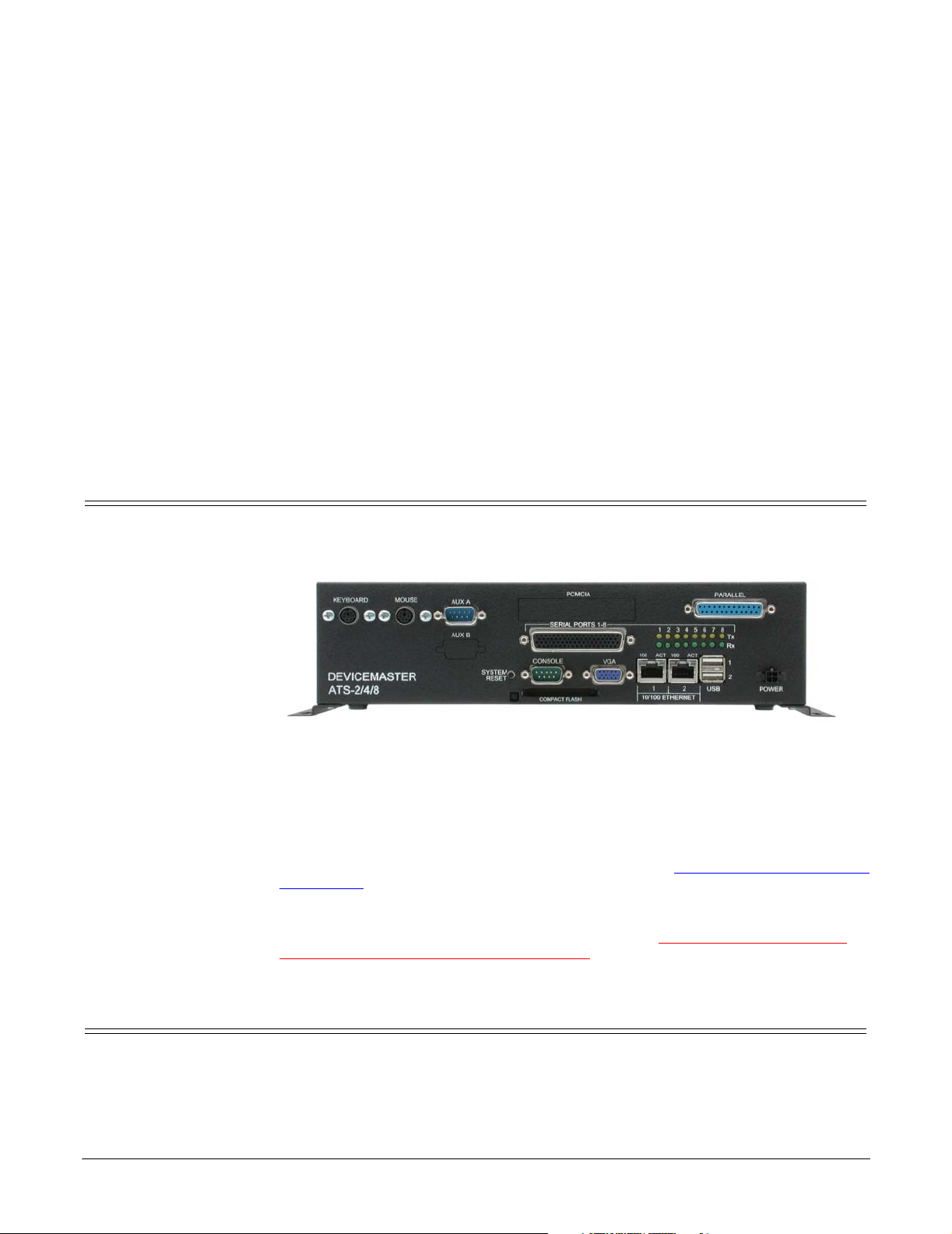
1. Place the DeviceMaster ATS-NTE on a stable
surface or attach it to a suitable surface
using the mounting brackets shipped with
the device.
2. Verify that the compact flash is fully
inserted. When installed correctly, the
compact flash is recessed into the ATS-NTE
and the eject button protrudes about 1/4
inch. If necessary, without using excessive
force or sharp objects, seat the compact flash
in its socket. Too much force can damage the
device.
3. Connect the 15-pin monitor cable from a standard VGA monitor to the VGA connector.
4. Connect a standard PS/2 compatible keyboard (6-pin mini DIN) into the KEYBOARD connector.
5. Connect a PS/2 compatible mouse (6-pin mini DIN) into the MOUSE connector.
Connect the devices appropriate for how you plan to use the ATS-NTE:
1. To dial-in and manage the ATS-NTE through a modem, connect an external
modem to the AUX A connector of the ATS-NTE.
If you want to connect a serial device (other than a modem) to this port, you
must turn off RAS and configure the port for your serial device. See Using the
AUX A Port as a COM Port on Page 48 to change the default port set up.
2. If you want to connect a parallel printer to the system, connect the printer
cable to the PARALLEL connector.
™
Note: The printer configuration supports the Epson
FX80.
3. Optionally, insert one of the Comtrol approved PCMCIA devices into one of the
PCMCIA slots.ThePCMCIAdevicemustbeinsertedintheslotifyouwantto
configure the device in the following sections.
Note: The ATS-NTE PCMCIA option supports two Type II PCMCIA slots or
one Type III slot, which is installed at the factory. Drivers for Comtrol
approved PCMCIA devices are installed in the system.
• Xircom® CreditCard™ Wireless Ethernet Adapter
Carefully align the adapter (with the flat side down, so that the Xircom
Activity and Status LEDs are visible from the top of the device) and gently
seat it into either the top or bottom rail of the PCMCIA slot.
• Xircom RealPort™ Modem 56 GlobalACCESS Adapter
a. Carefully align the adapter (with the flat side down, so that the
Xircom LED is on the left side) and gently seat it into the ATS-NTE.
b. Connect the phone line.
Note: If you refer to the Xircom Quick Start card, please note that the
driver is already installed and configured as COM3.
• PCMCIA to CompactFlash Adapter
a. Insert a compact flash into the PCMCIA to CompactFlash adapter.
b. Carefully align the PCMCIA adapter (compact flash facing up) with
the bottom rail and gently seat it into the ATS-NTE.
Installation and Setup 6
Page 7

Powering on the ATS-NTE
Note: The operating system only supports one PCMCIA to CompactFlash
adapter.
The PCMCIA compact flash will display as drive d: after logging in.
®
4. Optionally, connect the PC104 RocketPort
cable (quad- or octacable) to the
SERIAL PORTS 1-8 connector.
Note: If you have the PC104 RocketPort card option installed, do not connect
any RS-422 or RS-485 devices to the serial ports until you have
configured the driver.
Pow erin g on the
ATS -NTE
Other Installation and Configuration Procedures
After connecting the cables and devices, you can power on the ATS-NTE and login
to the operating system.
1. Connect the power cable into the power supply and connect the power supply
(with the latch and key up) into the POWER connector.
2. Connect the power cable to a power source.
Note: Thesystembeepsduringthepoweroncycle.IfyouhavetheRocketPort
PC104 option installed, solid yellow Tx LEDs also indicate that you
have power to the unit.
3. When prompted by Windows, press Ctrl + Alt + Del.
4. At the Windows Login prompt, enter the Administrator’s password.
Administrator is the default password and it is case-sensitive.
Note: After logging into the ATS-NTE, you will see three applications running on
your taskbar. These applications (WebServer.exe, SocketServer.exe,and
SystemManager.exe) must be running in the background to use these
applications. See ftp://ftp.comtrol.com/Dev_Mstr/ATS/NTE/
BrowserInterface for more information about these applications.
After the initial installation of the hardware there are other procedures you may
need to perform to complete installation and configuration of the ATS-NTE.
• If you want to connect and configure the ATS-NTE to a network (Ethernet or
PCMCIA wireless adapter), review and perform these procedures:
- Configuring the Network Settings on the ATS-NTE
on Page 8, for initial
setup.
- Changing the Default Computer and Workgroup Names
on Page 9, if you
are configuring multiple ATS-NTE units on your network.
- Configuring Dialin for NetMeeting
on Page 10, if you want to use
NetMeeting to control the ATS-NTE remotely.
• If you installed a modem (AUX A or PCMCIA) review and perform these
procedures:
- Configuring Dialin for NetMeeting
on Page 10, if you want to control the
ATS-NTE from a remote location.
- Setting Up
Remote Management starting on Page 11, to configure RAS
TCP/IP for an address pool.
• If you ordered the PC104 RocketPort option, see Configuring the Serial Ports
on Page 18 before connecting your serial devices.
Note: Only install serial device drivers for the Windows NT Embedded
operating system. Refer to the Customer Support Policy
on Page 53,
before installing any drivers.
• If you ordered a PCMCIA option, see the appropriate subsection for more
information:
- After you configure NetMeeting dialin and RAS, see Xircom RealPort
Modem 56 GlobalACCESS Adapter on Page 46 to load the Xircom Utilities
from the Xircom CD (V2.62). If using outside the United States or Canada,
Installation and Setup 7
Page 8

Configuring the Network Settings on the ATS-NTE
you will need the Xircom Utilities to set the modem country code.
- After you configure the network settings and NetMeeting dialin, see
Xircom CreditCard Wireless Ethernet Adapter
installation.
Configuring the Network Settings on the ATS-NTE
After installing the hardware, you are ready to configure the network. The ATSNTE provides Ethernet ports that function as two independent Ethernet network
interface cards and support for an optional wireless adapter in the PCMCIA slot.
Each network port must be connected to a different network segment or the ports
will conflict with each other. If the ports are not connected to different network
segments, NETBEUI will shut down all network services.
Note: Before you can configure the Xircom CreditCard Wireless Ethernet adapter,
it must be enabled. See Enabling the Ethernet Adapter
1. Log into the ATS-NTE as an
administrator. Administrator is the
default password and it is casesensitive.
2. Open the Network control panel and select the Protocols tab.
a. Highlight TCP/IP Protocol and
select Properties.
Note: Do NOT remove any of the
adapters from the network
because you cannot re-install
the drivers.
b. Select the adapter (1, 2, or 10) in
the drop list that corresponds to
network adapter you want to
configure. The default
c. network settings for the adapters
are:
Adapter#1
IP Address 192.168.250.251
Subnet mask 255.255.255.0
Gateway 192.168.250.1
Adapter#2
IP Address 192.168.255.252
Subnet mask 255.255.255.0
Gateway 192.168.255.1
Adapter#10
IP Address 192.168.245.253
Subnet Mask 255.255.255.0
Default Gateway 192.168.245.1
d. Make any necessary changes to the
IP address, selection by DHCP, or
other TCP/IP parameters.
e. Select Ok to close the Properties popup.
f. Select Close in the Protocol tab.
g. Select Yes to shutdown and restart the computer.
on Page 41, to complete the
on Page 41.
Installation and Setup 8
Page 9

Changing the Default Computer and Workgroup Names
3. Before the ATS-NTE reboots, connect a standard Ethernet cable to the
Ethernet port (or ports) that corresponds to the port (or ports) configured in
.
Step 2
The ports are labeled 1 and 2 (10/100 ETHERNET). For connector information,
see Ethernet Connectors
on Page 54. After the ATS-NTE boots and is running,
the green LED indicates receive activity and the yellow LED indicates
transmit activity on the network.
Changing the Default Computer and Workgroup Names
IfyouplanoninstallingmorethanoneATS-NTEonyournetwork,youmust
change the default computer name.
1. Right-click the Network Neighborhood icon and select Properties.
2. Select the Identification tab and the Change button.
3. Enteranewcomputernameand select Ok.
4. To change the Workgroup name, select the Change button, enter a new Workgroup name and select Ok.
5. Reboot the system so that the changes take affect.
Note: If you change the computer’s name
and you have installed the Xircom
CreditCard Wireless Ethernet
adapter, make sure that you change
thenameintheNetworkcontrol
panel (Step 3
on Page 42).
Installation and Setup 9
Page 10
Configuring Dialin for NetMeeting
NetMeeting can be used to access the Windows NT 4.0 Embedded desktop from a
remote location through a network connection (Ethernet or wireless) or a modem
connection (AUX A or PCMCIA modem). The desktop can be used to configure and
manage the ATS-NTE. Files can also be transferred through NetMeeting in the
event that the file sharing on the ATS-NTE is not available or enabled.
Use the following procedure if you want to use NetMeeting to control the ATSNTE.
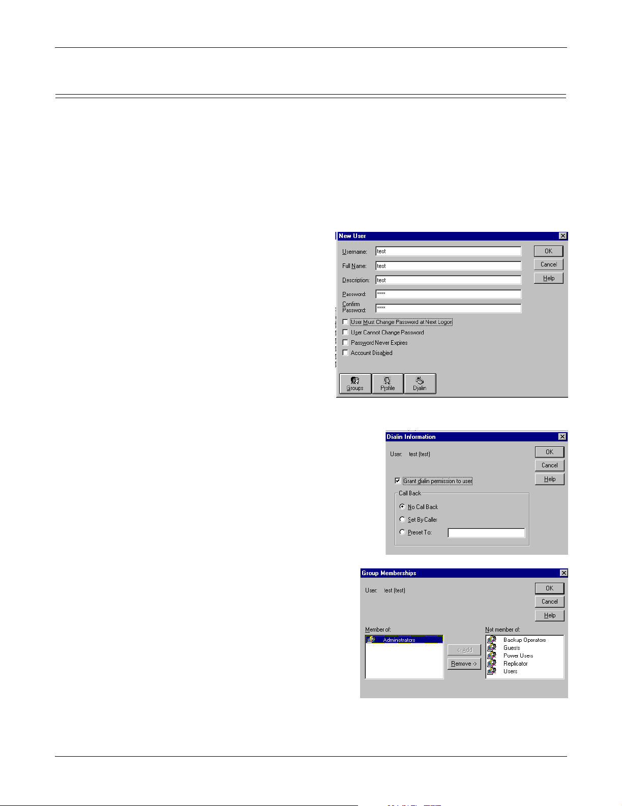
1. From the Start button, select Programs/ Administrative Tools (Common)/User Manager.
2. Select New User from the User menu.
3. Enter the new user name, the user’s full name, and a description.
4. Enter a password and confirm the password.
Note: NetMeeting requires
a password.
5. Uncheck User Must Change Password at Nex t Login.
Note: If you do not
uncheck this option,
the user must signon the ATS-NTE
before using
NetMeeting from a
remote site. NetMeeting does not permit you to change the password
when you log in.
6. Select the Dialin button.
Configuring Dialin for NetMeeting
7. Select the Grant dialin permission to
user option and then the Ok button to
close the Dialin Information pop-up. If
necessary, select the call back type.
8. Select the Groups button.
9. Make the user a Member of the Administrators group and select the Ok button.
10. Select Ok to close the New User pop-up.
11. Exit the User Manager.
Note: You may be requested to
provide a new password
the first time you sign in
with the new user name.
Installation and Setup 10
Page 11
Setting Up Remote Management
Before setting up remote management, make sure that you have already
performed the procedures in Configuring Dialin for NetMeeting on Page 10. The
ATS-NTE has the following drivers installed that require additional configuration
for remote management:
• A standard 28.8 Kbps modem driver for AUX A with Remote Access Service
(RAS) enabled on COM2.
• Xircom RealPort Modem 56 GlobalACCESS adapter driver that is installed on
COM3.
Review and perform the following procedures if you want to manage the ATS-NTE
from a remote (client) site:
• Configuring RAS TCP/IP for Dialin (below)
• Client Configuration
Setting Up Remote Management
on Page 13
Configuring RAS TCP/IP for Dialin
To use NetMeeting on a dialin connection with AUX A or the Xircom modem, you
must change the RAS TCP/IP configuration.
Note: If you plan on configuring the Xircom CreditCard Wireless adapter, you
must enable the device (Enabling the Ethernet Adapter
on Page 41) before
any changes to the network bindings. Failure to do so before configuring
RAS will “orphan” the Xircom wireless adapter from the TCP/IP stack.
That is, this adapter will lose its pre=-configured binding to the network
protocols and services.
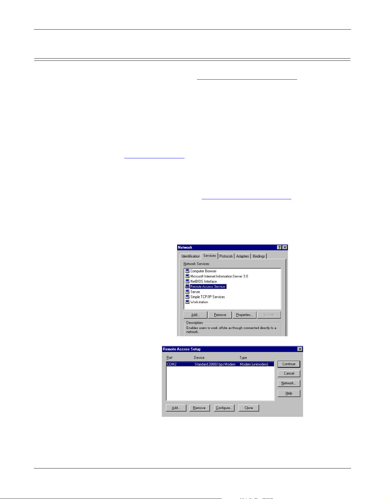
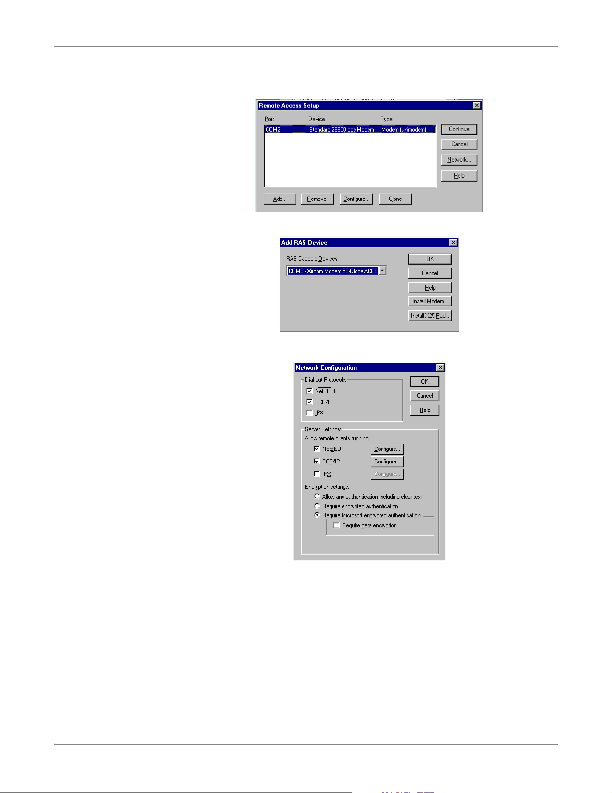
1. Open the Network control panel and select the Services tab.
2. Highlight Remote Access Service and select the Properties button.
3. To configure a modem on AUX A, select the Network button and go to Step 5.
Note: If you want to configure the Xircom Modem 56-Global modem with Receive
calls only or Dial Out and Receive Calls capabilities, you must change
COM2 to a dial out only configuration.
Installation and Setup 11
Page 12
Configuring RAS TCP/IP for Dialin
4. To configure the Xircom Modem 56-GlobalACCESS modem:
a. Select the Add button.
b. Select COM3 - Xircom Modem 56-GlobalACCESS from the RAS Capable
Devices drop list and select Ok.
c. Go to Step 5.
5. Select the TCP/IP Configure button.
Installation and Setup 12
Page 13
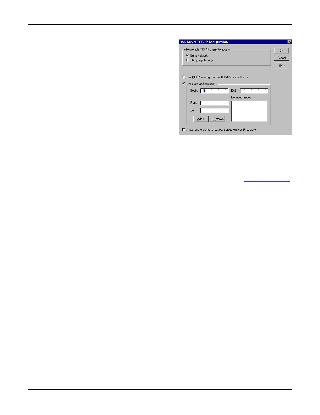
6. Select Use static address p ool,
enter a range of valid IP
addresses, and then select the
Ok button to close the RAS
Server TCP/IP Configuration
popup.
Note: You may want to note
the Begin number
assigned to the pool
because you will need
that IP address if
dialing in through
NetMeeting.
7. Select Ok to close the
Network Configuration
popup.
8. Select the Continue button in
the Remote Access Setup
popup.
9. Select the Close button in the Network window.
10. Shutdown and restart the system as prompted.
Client Configuration
Client Configuration Before you can manage the ATS-NTE remotely, you must set up a dial up network
connection on the client. To initiate a NetMeeting session, see A
ccessing the ATS-
NTE on Page 14.
Installation and Setup 13
Page 14

Using NetMeeting
Managing Files on the ATS-NTE
You can share the ATS-NTE and use Windows Explorer to access or move files or
applications to or from any remote system. In addition, you may want to use
NetMeeting to control the ATS-NTE from a remote (client) system.
Note: Compact flash technology does not support an unlimited number of writes.
Use the compact flash to store applications but avoid using it for file storage.
If your application generates files, save the files on a remote system.
NetMeeting can be used to control the ATS-NTE from a remote location and to
transfer or retrieve files through a modem or a network connection.
Accessing the ATSNTE
Use the following procedure to access the ATS-NTE from a remote (client) system.
Note: The ATS-NTE must have been previously configured with a user name and
password that has dial-in privileges, see Configuring Dialin for NetMeeting
on Page 10.
1. If you are using a modem, create a dialup connection to the ATS-NTE and
make the connection to the ATS-NTE.
2. Start up NetMeeting on the client. The following shows the steps for a Windows NT client:
a. Start NetMeeting from the Start button
Programs/Accessories/Communications/
NetMeeting.
b. Select Call and New Call.
c. Enter the IP address of the ATS-NTE, check
security call, and select Call.NetMeeting
requires that the call be secure.
Note: If connecting through a modem, use the beginning static IP address
Managing Files on the ATS-NTE 14
that was assigned in C
11.
onfiguring RAS TCP/IP for Dialin on Page
Page 15
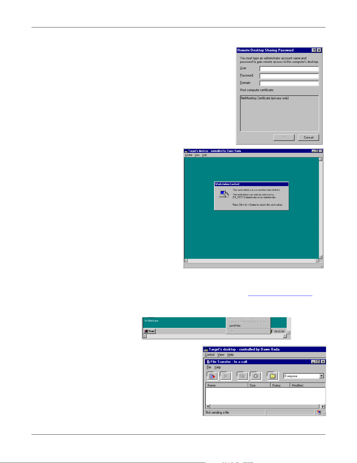
d. Enter the user name and password
you created on the ATS-NTE with
dialin privileges and select Ok.Leave
theDomainnameblank.
Note: IftheRemoteDesktopSharing
Password popup returns after
selecting Ok, check with the
Administrator to see if your
user name was set up without
the need to change the
password during the first login.
NetMeeting cannot change your
password.
The ATS-NTE will appear on your remote
desktop.
3. Select the Control menu and then Send Ctrl+Alt+Del to log onto the ATS-NTE.
Retrieving Files from the ATS-NTE
Retrieving Files
from the ATS-NTE
Use the following procedure if you want to retrieve a file from the ATS-NTE.
1. Start up NetMeeting on the remote system. (Use A
ccessing the ATS-NTE on
Page 14, if necessary).
2. After accessing the ATS-NTE, right-click on the NetMeeting Remote Desktop
Sharing icon in the ATS-NTE task bar and select Send files.
3. Select Add Files in the File menu and select the files you want to transfer.
4. Select Send All or Send a File from the File menu.
5. Close the Transfer Complete pop-ups.
The files are copied into the
C:\Program
Files\NetMeeting\Received Files
subdirectory.
Managing Files on the ATS-NTE 15
Page 16

Sending Files to the ATS-NTE
Sending Files to the
ATS -NTE
Use the following procedure if you want to send a file to the ATS-NTE.
Note: Compact flash technology does not support an unlimited number of writes.
Use the compact flash to store applications but avoid using it for file storage.
If your application generates files, save the files on a remote system.
1. Start up NetMeeting on the remote system. (Use A
ccessing the ATS-NTE on
Page 14, if necessary).
2. Select File Transfer from the Tools menu.
3. Select AddFiles from the File menu and select the files you want to transfer.
4. Select Send All or Send a File from the File menu.
5. Close the Transfer Complete popup.
The files are copied into the
C:\Winnt\rds\Received Files subdirectory.
Managing Files on the ATS-NTE 16
Page 17

PC104 RocketPort Option
The PC104 RocketPort serial card is optional in the DeviceMaster ATS-NTE.
Note: This option can only be installed by Comtrol.
This section discusses the following topics:
• PC104 RocketPort default settings.
• Configuring the serial ports for your serial devices. Review Default PC104 Port
Configuration (below) to determine whether you need to reconfigure any of the
default settings.
Note: ThedriverdefaultfortheportsisRS-232.
• Connecting your serial devices to the ATS-NTE.
• Adding modems on the serial ports:
- Using the ATS-NTE default driver.
- Using the modem manufacture’s driver.
• RocketPort quad- or octacable:
- Connector pinouts
- Building loopback plugs
- Building cables (null-modem and straight-through).
• Troubleshooting serial ports with Comtrol tools (Test Terminal and PortMon).
• Device driver and operating system capabilities and limitations.
Default PC104 Port Configuration
This subsection lists the default configuration values for the RocketPort PC104. If
these settings are suitable for your installation, you do not need to configure the
driver and can begin connecting your devices using Configuring the Serial Ports
Page 18.
Mode RS-232
StartingCOMPort COM4(seePage18formoreinformation)
Verb o se Event lo g Of f
Scan Rate 10 ms (see Page 21 for more information)
Overrideandlockbaudrateto None
Timeoutontransmitdataonportclose 0sec
Map 2 stop bits to 1 Disabled
Wait on physical transmission before
completing write
on
Item Default Value
Disabled
PC104 RocketPort Option 17
Page 18
Configuring the Serial Ports
Use the following procedure if you need to reconfigure the driver for your serial
devices.
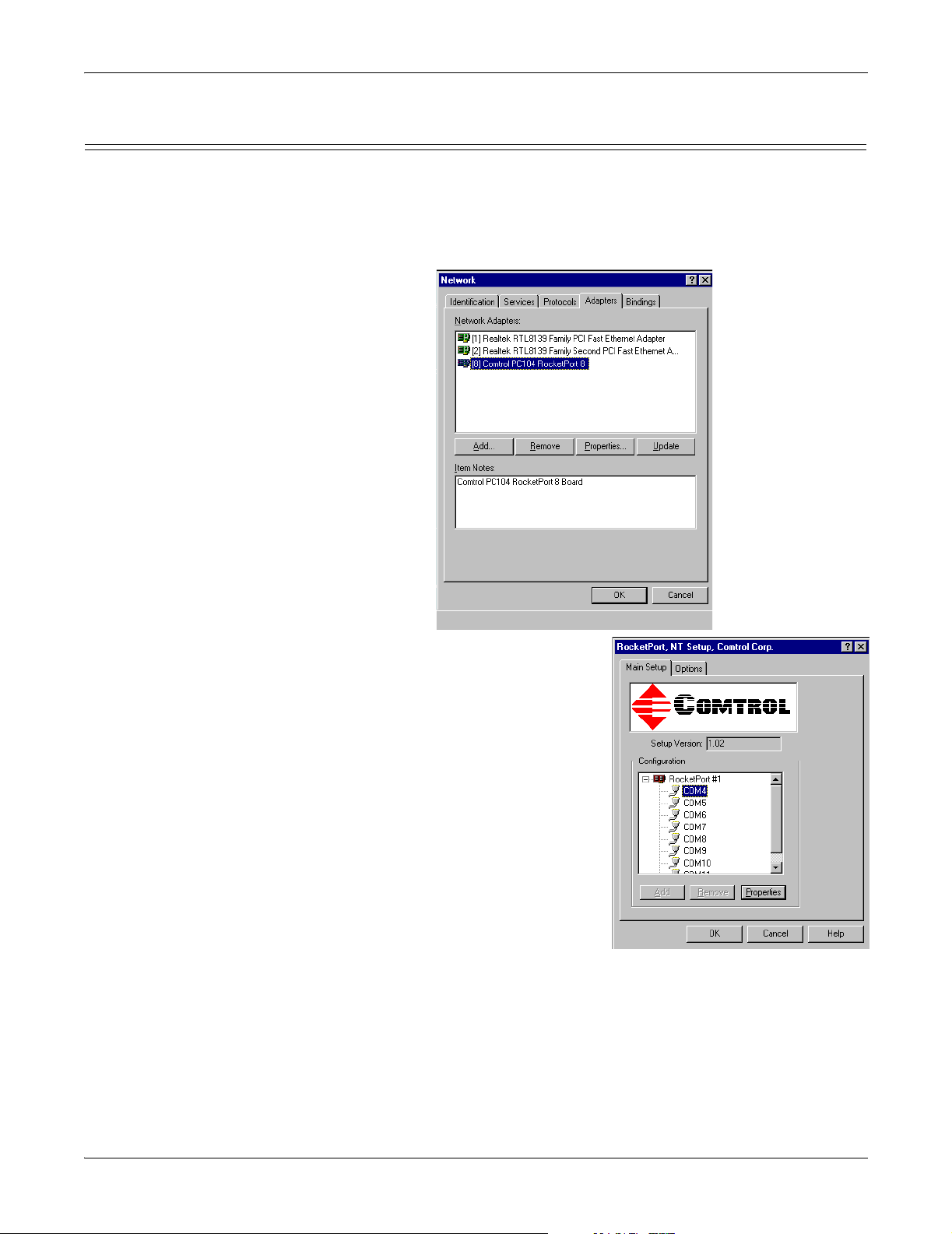
1. Right-click the Network Neighborhood icon and select Properties.
2. Select the Adapters tab.
3. Highlight Comtrol RocketPort and select the Properties button.
Configuring the Serial Ports
4. Highlight the port for which you want to
configure COM port characteristics and
select Properties.
Note: COM4 is the default starting
COM port.
• COM1 is assigned to the CONSOLE
port.
• COM2 is assigned to the AUX A port.
• COM3 is assigned to the optional
PCMCIA Ethernet/Modem cards.
PC104 RocketPort Option 18
Page 19

Configuring the Serial Ports
a. Change the communications
mode to match the device you
plan to connect.
b. If necessary, set an Override
andlockbaudratetovalue.
This option lets you lock
selected ports to specific baud
rates. After you do so, no
matter what baud rate is
selected in a host application,
the actual rate used is the
rate specified here.
c. If necessary, set the Time on
transmit data on port close
value.
Use this drop list to select the length of time to wait for data to clear the
transmit buffer after a host application has closed the port. This is typically
used with peripheral devices such as printers, to give the data sufficient
time to flush through the system.
d. If necessary, select the Map CD to DSR option.
This option is used in installations where there is no connection to the
port’s DSR input. Check this box to cause the CD input to appear as DSR
to the host application, and to perform hardware handshaking with CD
rather than DSR. This is ignored if flow control is not enabled via
IOCTL_SERIAL_SET_HANDFLOW.
e. If necessary, set the Wait on physical transmission before completing write
option.
This option forces all write packets to wait until the transmit data has
physically completed the transmission before returning completion to the
host application. The default mode (box not checked) is to buffer the data in
the transmit hardware buffer, and return completion as soon as the packet
is in the buffer.
f. Select the Clone option if you want to clone all of the ports on the adapter
with the characteristics set in this port.
Note: If this box is not checked, changes apply to the selected port only.
g. Select Ok to make the changes to
the selected port.
If you select 485 as the RS Mode,
this popup appears.
h. Repeat Step 4 for each port that
requires configuration.
PC104 RocketPort Option 19
Page 20
Configuring the Serial Ports
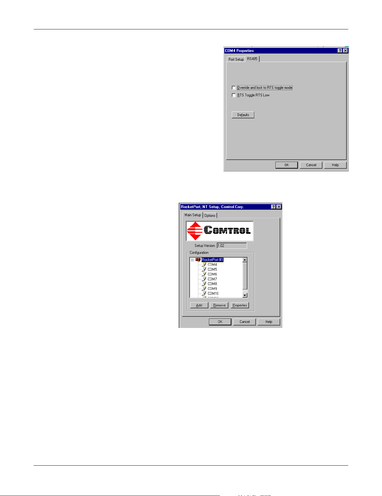
5. If you selected RS-485 as the
communications mode, highlight
the port, select Properties and
then the RS-485 tab.
a. Check the Check the RS-485
Port Properties - RTS Toggle
RTS Low boxtotogglethe
RTS output signal low during
data transmission. If this box
is not checked, RTS is toggled
high (asserted) during data
transmission.
b. Check the RS-485Port
Properties - Override and lock
to RTStogglem ode box to lock
theportinRTStogglemode,
then set the mode (low or
high) as desired. If this box is
not checked, the RTS output
signal is ignored.
c. Select Ok to make the changes to the selected port.
6. To change the name of the PC104 RocketPort adapter or the starting COM
port number, highlight RocketPort #1 and select Properties.
PC104 RocketPort Option 20
Page 21
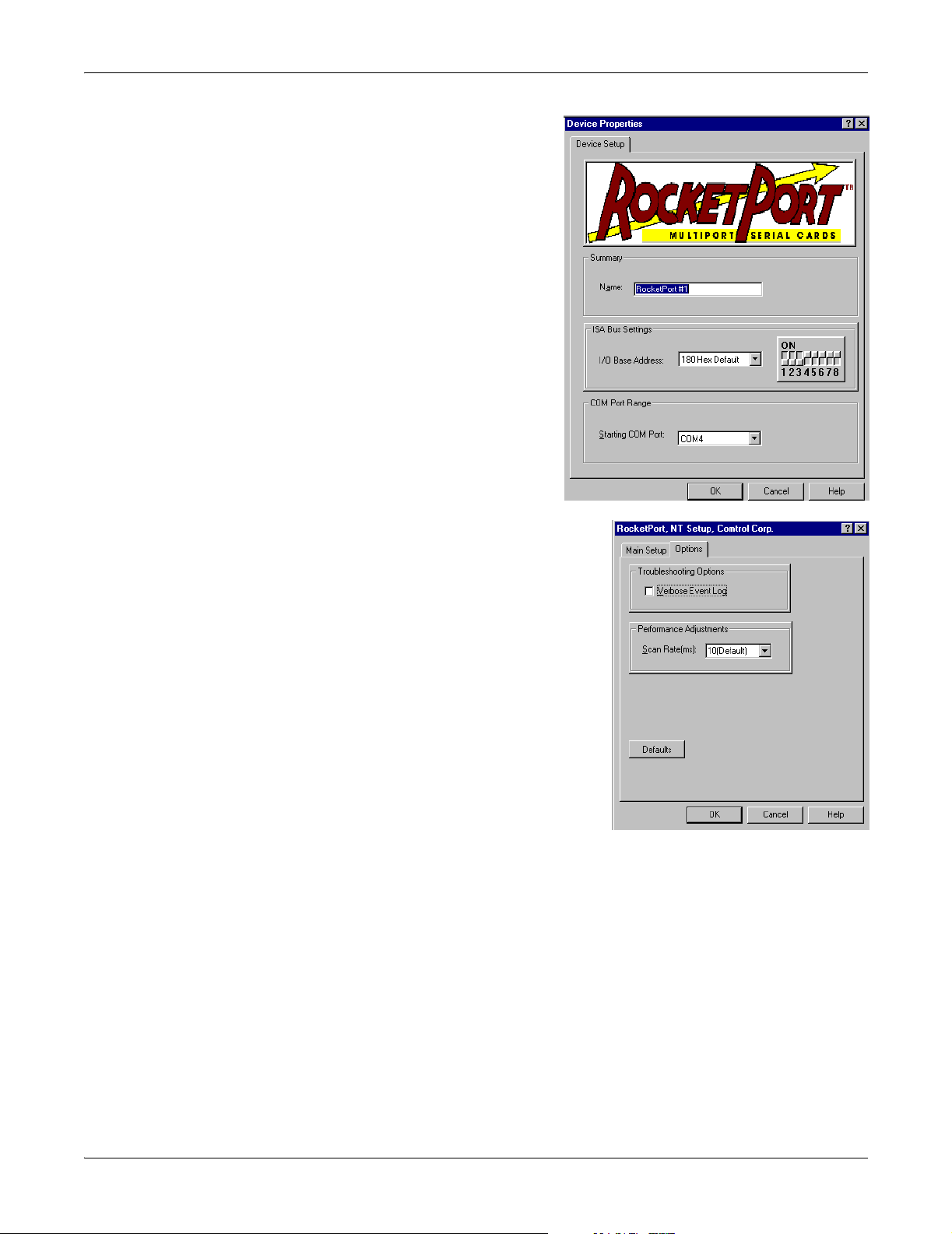
a. Change the Name or the
Starting COM Port number.
Note: Do not change the I/O
Base Address. It is
preset at the factory
and it cannot be
changedinthefield.
• COM1 is assigned to the
CONSOLE port.
• COM2 is assigned to the
AUX A port.
• COM3 is assigned to the
optional PCMCIA
Ethernet/Modem card.
The default starting COM port
number is COM4.
b. Select Ok to return to the
Main Setup screen.
Configuring the Serial Ports
7. If you want to set the verbose event log or change the scan rate, select the Options tab.
a. Check Verbose Event Log if you want
more information logged in to the
Event Viewer when the driver loads.
b. Use the Scan Rate drop list to select a
driver servicing rate.
8. Select Ok to close the Setup window.
9. Select Ok to close the Network window.
10. Reboot if requested by the system.
PC104 RocketPort Option 21
Page 22

Connecting Serial Devices
The COM ports provided by the SERIAL PORTS1-8 can support any asynchronous
serial modem for use by any application that uses TAPI.
There is a remote possibility that connecting a peripheral using the wrong
configuration (RS-232 device connected to a RS-422 configured port)could
damage the peripheral. Configure each serial port specifically for the peripheral
that will be connected prior to connecting the peripheral to the ATS-NTE. See
Configuring the Serial Ports
on Page 18 for information about configuring port
characteristics.
Note: If your serial devices require a driver that does not support the Windows NT
Embedded system, contact Comtrol before driver installation.
Connect your serial devices to the configured ports using the appropriate cables. If
you need to build cables, see RocketPort Serial Port Connectors
Installing Modems on the RocketPort Serial Ports
A standard 28800 bps modem driver is built into the ATS-NTE image. To add
additional modems that use the standard driver, see Using the ATS-NTE
Standard Modem Driver (below).
If you want to install a specific driver for your modems on the RocketPort serial
ports (SERIAL PORTS 1-8), see Using the Modem Manufacturer’s Driver
26.
Connecting Serial Devices
on Page 29.
on Page
Using the ATS-NTE Standard Modem Driver
Use the following procedure if you want to use the standard modem driver
configured in the ATS-NTE.
1. Connect the modem to the serial port you want to configure. The connector labeled P0 by default corresponds to COM4 (unless you changed
the starting COM port number in the driver setup to a higher number).
• COM1 is assigned to the CONSOLE port.
• COM2 is assigned to the AUX A port.
• COM3 is assigned to the optional
PCMCIA Ethernet/Modem card.
2. Open the Modem control panel and select the Add button.
3. Check the Don’t detect my modem... box and select Next.
PC104 RocketPort Option 22
Page 23

Using the ATS-NTE Standard Modem Driver
4. Highlight Standard 28800 bps Modem and select the Next button.
5. Select the COM port that corresponds to the port number. This example shows
connecting a modem to the P0 connector (with the COM4 as the starting COM
port number).
6. Select Ok to the Modem Setup popup to restart the system.
7. Select Finish.
PC104 RocketPort Option 23
Page 24

Using the ATS-NTE Standard Modem Driver
8. Select Close.
9. Select No, and shutdown and reboot the ATS-NTE.
10. After rebooting the system, open the Network control panel, select the Services
tab, highlight Remote Access Service, and select Properties.
11. Select the Add button.
12. Select the COM port number that corresponds to COM port installed in Step 5 and select Ok.
PC104 RocketPort Option 24
Page 25

Using the ATS-NTE Standard Modem Driver
13. Select the Continue button.
If you have previously configured a static address pool for RAS TCP/IP, select
Ok when this message appears.
Adjust the RAS Server TCP/IP Configuration screen as necessary.
Note: If you want to configure this modem with Receive calls only or Dial Out
and Receive Calls capabilities, you must change COM2 to a dial out
only configuration.
14. Select Yes, shutdown, and restart your ATS-NTE.
PC104 RocketPort Option 25
Page 26

Using the Modem Manufacturer’s Driver
Using the Modem
Manufacturer’s
Driver
1. If you want to use a modem driver that supports more than the standard
28800 bps default driver in the ATS-NTE, install the modem driver using the
manufacturer’s instructions.
2. Connect the modem to the serial port you want to configure. The connector labeled P0 by default corresponds to COM4 (unless you changed
the starting COM port number in the driver setup to a higher number).
• COM1 is assigned to the CONSOLE port.
• COM2 is assigned to the AUX A port.
• COM3 is assigned to the PCMCIA Ethernet/modem cards.
3. Open the Modem control panel and select the Add button.
4. Check the Don’t detect my modem... box and select Next.
5. Select the modem manufacturer and model from the lists, and select Next.
PC104 RocketPort Option 26
Page 27

Using the Modem Manufacturer’s Driver
6. Select the COM port number that corresponds to the port number. This
example shows connecting a modem to the P0 connector (with the COM4 as
the starting COM port number).
7. Select Finish.
8. Select Close.
9. Select No, and shutdown and reboot the ATS-NTE.
10. After rebooting the system, open the
Network control panel, select the Services
tab, highlight Remote Access Service,and
select Properties.
PC104 RocketPort Option 27
Page 28

Using the Modem Manufacturer’s Driver
11. Open the Remote Access Setup window and select the Add button.
12. Select the COM port number that corresponds to COM port installed in Step 6andselectOk.
13. Select the Continue button to close Remote Access Setup. If you have previously configured a static address pool for RAS TCP/IP, select
Ok when this message appears.
Adjust the RAS Server TCP/IP Configuration screen as necessary.
14. Select Yes, shutdown, and restart your ATS-NTE.
PC104 RocketPort Option 28
Page 29

RocketPort Serial Port Connectors
The following subsections illustrate the pinouts for the quad- and octacable
connector types and how to build loopback plugs for testing serial ports.
RocketPort Serial Port Connectors
DB9 Connectors This illustrates
the pinouts for
DB9 quad- or
octacables.
Building Additional DB9 Loopback Plugs
Loopback connectors are DB9 female serial port plugs that you can use to test
serial ports. The ATS-NTE is shipped with a a single loopback plug (RS-232/422)
that corresponds to your quad- or octacable type.
Note: You can run loopback tests with Test Terminal.
Wire the following pins together to build additional plugs or replace a missing RS232 loopback plug:
•Pins1to4to6
•Pins2to3
•Pins7to8to9
Wire the following pins together for an RS-422 loopback plug:
•Pins2to3
•Pins7to8
GND
DTR
TxD
RxD
CD
Pin 1
Pin 1
Pin 6
RS-232
Pin 1
Pin 6
Pin 6
RI
CTS
RTS
DSR
Not used*
Not used
TxDRxDNot used
Pin 5
Pin 9
Pin 5
Pin 9
RS-422
Pin 1
Pin 6
RS-232 Only
(Back View)
RS-422 Only
(Back View)
RS-485
Not used
RxD+
TxD+
Not used
Not used*
Not used
TxD/RxDNot used
Not used
Pin 1
* Pin 5 is tied to ground on the board,
but is not used in the cable.
The RS-232 loopback plug
also works for RS-422.
Not used
Not used
TxD/RxD+
Not used
Pin 6
DB25 Connectors This illustrates the pinouts for DB25 quad - or octacables.
RS-232
DCD
Signal Gnd
DSR
CTS
RTS
RxD
TxD
Pin 1
RI
DTR
Pin 14
RS-422
Signal Gnd
TxD+
RxD+
RxDTxD-
Pin 1
Pin 14
RS-485
Signal Gnd
TxD/RxD+-
TxD/RxD-
Pin 1
Pin 14
PC104 RocketPort Option 29
Page 30

Building Additional DB25 Loopback Plugs
Building Additional
DB25 Loopback
Plugs
Loopback connectors areDB25femaleserialportplugsthatyoucanusetotest
serial ports. The ATS-NTE is shipped with a a single loopback plug (RS-232/422)
that corresponds to your quad- or octacable type.
Note: You can run loopback tests with Test Terminal.
Wire the following pins together to build additional plugs or replace a missing RS232 loopback plug:
.
•Pins2to3
•Pins4to5to22
•Pins6to8to20
Pin 1
Pin 14
The RS-232 loopback plug
.
Wire the following pins
together for an RS-422 loopback plug:
•Pins2to3
•Pins4to5
Pin 1
Pin 14
RS-422 Only
(Back View)
RJ45 Connectors This illustrates the pinouts for RJ45 quad- or octacables.
Pin 1
RJ45
RS-232
RTS
DTR
Signal GND
TxD
RxD
DCD
DSR
CTS
RJ45
Pin 1
RS-422
TxD+
Not used
Not used**
TxDRxDNot used
Not used
RxD+
** Pin 3 is tied to ground on the board,
butisnotusedinthecable.
RJ45
RS-232 Only
(Back View)
also works for RS-422.
Pin 1
RS-485
TxD/RxD+
Not used
Not used**
TxD/RxDNot used
Not used
Not used
Not used
Building Additional RJ45 Loopback Plugs
Building an RS-485 Tes t C a b le
Loopback connectors are RJ45 serial port plugs that can be used to test serial
ports. The ATS-NTE is shipped with a a single loopback plug (RS-232/422) that
corresponds to your quad- or octacable type.
Note: You can run loopback tests with Test Terminal.
•Pins4to5
•Pins1to8
•Pins2to6to7
18
Plug
Top View
Cable
The RS-232 loopback plug also
works for RS-422.
You can use a straight-through cable as illustrated previously, or build your own
cable.
Signal
TxD or TRX-
RTS or TRX+
RJ45
Pins
4
1
DB9
Pins
3
7
RJ45
Pins
4
1
DB25
Pins
2
4
Signal
TxD or TRX-
RTS or TRX+
PC104 RocketPort Option 30
Page 31

Building Null-Modem Cables
Building NullModem Cables
Building StraightThrough Cables
Use the following figure if you need to build a null-modem cable. A null-modem
cable is required to connect the CONSOLE port to a PC COM port or to connect
DTE devices.
Signal
TxD
RxD
RTS
CTS
DSR
DCD
DTR
GND
ATS-N TE Female
RI
DB9
Pins
3
2
7
8
6
1
4
5
9
DB25
Pins
2
3
4
5
6
8
20
7
22
RJ45
Pins
4
5
1
8
7
6
2
3
N/A
DB9
Pins
2
3
8
7
4
1
6
5
9
DB25
Pins
3
2
5
4
20
8
6
7
22
RJ45
Pins
5
4
8
1
2
6
7
3
N/A
Signal
RxD
TxD
CTS
RTS
DTR
DCD
DSR
GND
RI
PC COM Port
Note: You may want to purchase or build a straight-through cable and purchase a
null-modem adapter.
Use the following figure if you need to build a straight-through cable. Straightthrough cables are used to connect DCE devices.
RJ45
Signal
DCD
RxD
TxD or TRxDTR
GND
DSR
RTS or TRx+
CTS
ATS-NTE Female
RI 9
DB9
Pins
1
2
3
4
5
6
7
8
RJ45
Pins
6
5
4
2
3
7
1
8
N/A
DB9
Pins
1
2
3
4
5
6
7
8
9RI
Pins
6
5
4
2
3
7
1
8
N/A
DB25
Pins
8
3
2
20
7
6
4
5
22
Signal
DCD
RxD
TxD or TRxDTR
GND
DSR
RTS or TRx+
CTS
Troubleshooting Serial Ports
The following subsections discuss the following utilities that are installed on the
ATS-NTE:
•TestTerminalprogram(wcom32.exe), which can be used to troubleshoot
communications on a port-by-port basis.
• Port Monitor program (portmon.exe), which checks for errors, modem control,
and status signals (Using Port Monitor
you with raw byte input and output counts.
• Peer Tracer program (peer.exe), which traces driver events (Using Peer Tracer
on Page 38).
Using Test Terminal WCOM32 is a terminal program that enables you to open a port, send characters
and commands to the port, and toggle the control signals.
Note: WCOM32 will not work on ports used by RAS if Remote Access Service is
running or any other application is using the port.
If you have started RAS service on any of the ports you want to test, you
must stop RAS on those ports before starting WCOM32. To test ports that
are not used by RAS, you do not need to stop RAS.
on Page 33). In addition, it provides
PC104 RocketPort Option 31
Page 32

Testing a Comtrol Port
Follow these steps:
1. To start
WCOM32, select
Test Terminal
from theComtrol
program group.
The program
window displays:
2. Select Open Port from the Port menu. A list of possible COM port numbers displays.
3. Select the COM port you want to test. If the COM port does not exist or if it is currently being used by another
program, a Create File Error message displays.
If the COM port is
available, a terminal
window pops up:
Note: Notice the <loop>
button in the
terminal window.
If this option is
activated, it is
green and
uppercase ( ),
the COM port
internal loopback
feature is activated,
and the data is
returned by the
COM port hardware. If this option is deactivated, it is gray and
lowercase ( ), the internal loopback is deactivated, and the data is
sent out the COM port.
Testing a Comtrol
Port
Use the following procedure to test the RocketPort PC104 serial port.
1. Place a loopback plug on the COM port you are testing. Make sure all
connectors are seated firmly and that the loop button is off.
Note: Test terminal works for RS-232 and RS-422 mode.
To build loopback plugs, see Building Additional DB9 Loopback Plugs
29, Building Additional DB25 Loopback Plugs on Page 30, or Building
Additional RJ45 Loopback Plugs on Page 30.
2. From the Portmenu, select
Send Test Data.The
program sends out a
repeating data stream.
Note: To stop the data
stream, select Send
Test Data again.
• If the loopback plug is
inplaceandtheportis
working correctly, the
test data should be
echoed back to the
screen.
•Iftheloopbackplugisnot in place or the port is not working correctly, no
data or garbled data is echoed back to the screen.
on Page
PC104 RocketPort Option 32
Page 33

Testing an RS-485 Port
Note: If no characters appear, try putting the loopback plug on an adjacent
port. It may be that you have the ports mixed up.
3. If further testing is required, select Loopback Test from the Port menu. If the loopback plug is in place and the port is
working correctly, the system should return the
message Passed.
If the loopback plug is not in place or the port is
not working correctly, the system will return the
message Failed.
Testing an RS-485
Port
Test Terminal Modem Control Signals
Perform the following procedure to determine if a port or ports are functioning
properly.
1. Connect a straight-through cable from Port 1 to Port 2.
Note: See Building an RS-485 Test Cable
on Page 30 for the cable
information. If testing ports other than Ports 1 and 2, connect the cable
between the two ports being tested.
2. Open a session for each port.
3. Enter data into the Port 1 session, the data should appear in the Port 2 window.
4. Enter data into the Port 2 session, the data should appear in the Port 1 window.
Note: If the data appears as described in Steps 3 and 4, the hardware is
functioning properly.
The terminal window displays the modem control signals as gray
or green lights at the top of the window. The first four are inputs:
The lights are green if they are turned on, or gray if off. The text
on the light also changes from uppercase (CTS), which is on, to lowercase (cts),
which is off.
The next two lights are outputs:
Note: If you have a loopback plug connected and you click on one of the outputs,
the corresponding signal is sent to the input and the input lights should
toggle accordingly.
The right most light is the loop indicator:
If this is on, the COM port internal loopback feature is activated and any
information or code entered in the terminal window loops back through the COM
port circuitry. If this is off, the COM port internal loopback is deactivated, and any
information or code entered in the terminal window is sent out of the port.
Using Port Monitor The Port Monitor program (portmon.exe) offers a summary of all Comtrol device
statistics in one spreadsheet view. It also enables you to verify operation of all
Comtrol device ports from a single window.
The Port Monitor display follows the familiar spreadsheet model: each COM port
is a horizontal row, and each vertical column displays a variable or value for the
respective COM port. For definitions of the abbreviations used, see Port Monitor
Variables on Page 37.
Port Monitor can also produce statistics and reports that can help you verify the
operation of the COM ports and connected peripherals. Some immediate feedback
includes:
• The state of the modem control and status signals
•Openports
• Raw byte input and output counts obtained from NS-Link
• Port errors
PC104 RocketPort Option 33
Page 34

Starting Port Monitor
The available statistics include:
• Instantaneous characters per second (CPS) calculations
• Minute, hour, and day CPS averages and peaks
• Carrier detect (CD) signal runtime and transition count
Reports can be automatically generated on an hourly and/or daily basis, and can
cover all ports collectively or a separate report for each port. You can also set how
often the values are recalculated, fine-tuning thoroughness against system
efficiency, and automatically run external batch files to perform additional
processing and analysis.
Starting Port
Monitor
Changing Screen Appearance
To run Port Monitor, select Port Monitor from the Comtrol program group. The
monitor window displays:
Note: To change the appearance of the screen, see the following discussion.
Once the monitor window displays, Port Monitor is active and collecting data. If
any cumulative data has been saved from previous sessions, it is automatically
brought in and used.
Port Monitor continues to run and collect data until you terminate it, at which
point all accumulated data is automatically saved for use in the next session.
While Port Monitor is running, there are a number of commands and controls that
change the appearance of the screen.
Desired Change Procedure
Change the monitor
window font.
Change width of a
single column.
Change column
placement.
Remove a column.
Clear all fields and
reset them to null
values.
Clear any single field
except the upper left
cell.
PC104 RocketPort Option 34
Select Font from the Edit menu.
Left-click on the column separator (vertical) line and
drag it to the desired width.
Left-click in the middle of the column you want to
move and drag it to the desired location.
Right-click on the column you want to remove and
select Remove from the pop-up menu.
Right-click on the upper left cell in the table and select
Reset from the pop-up menu.*
Right-click on the field to be cleared and select Reset
from the pop-up menu.*
Page 35

Desired Change Procedure
Right-click on the column now occupying the desired
location and select Add from the pop-up menu.
You are prompted to name the variable you want to
Add a column.
display, as well as other information. (See Column
Setup,below.)
After you click OK, the column is inserted in the
selected location and the existing column is moved to
the right.
Change otherproperties
of a column.
Right-click on the column and select Properties from
the pop-up menu. (See Column Setup, below.)
*TheReset command does not clear raw data from the calcs.dat file. It simply
resets the selected display fields to their null values.
Column Setup When you select Add or Properties from
the column pop-up menu, the Column
Setup window displays:
•UsetheInput drop list to select the
variable displayed in the column.
•UsetheType drop list to select the
way in which the value displays:
either as an integer, as an on/off
state, as an integer with a kilo,
mega, or giga suffix, or as an
hh:mm:ss time stamp. This defaults
totheappropriatetypeforthe
selected Input variable.
•UsetheName variable to change
the column heading name.
•UsetheWidth variable to specify
the column width in characters.
•UseColor0 to set the column character color when the value is zero.
•UseColor1 to set the column character color when the value is not zero.
• When done, click OK to save your changes and return to Port Monitor.
Column Setup
Report Configuration
To configure reports, select
Config from the Edit menu.
The Single report options
cover all ports and are
overwritteneachtimethe
reports are generated. The
Multiple report options
generate a separate report
for each port, and each
report file is appended each
time the report is generated.
For Hour reports, use the
Single and Multiple drop
lists to select whether you
are generating single or
multiple reports, or both.
For each report type, select
from the following types of data to include:
• None: no report is generated.
PC104 RocketPort Option 35
Page 36

Port Monitor Files
• Hour Data: only variables with “Hour” in the name are included.
• All Data: all variables are included.
• View Data: only variables that appear on-screen are included.
The External Program field is used to enter a command line to run another
program after the hourly reports have been generated. For example, you can use
this to run a batch file that performs custom report processing. The Test button
causesthecommandlinetobeexecutedimmediately.
For Day reports, the single and multiple drop lists behave the same, but your
choices are:
• None: no report is generated.
• Day Data: only variables with the words “Day” or “Raw” in the names are
included.
• All Data: all variables are included.
• View Data: only the variables that appear in the Port Monitor window are
included.
Likewise, the External Program fieldisusedtoenteracommandlinetobe
executed after the daily reports have been generated.
The Update Time option allows you to set the rate at which the port information is
obtained and the calculations performed. There is a trade-off between Port
Monitor efficiency and response time. If you are using Port Monitor to view the
port activity on the screen, you may want to set the update time to 1 or 2 seconds,
so that the screen is updated frequently. If you are concerned about the monitor
program using CPU resources, set this to a higher value, (6 to 20 seconds) in order
to decrease the time required by the program to perform the calculations and
update the screen.
If Port Monitor is left active to generate reports, minimizing or reducing the
display area of the program will help reduce the CPU overhead of updating the
screen.
Port Monitor Files Port Monitor creates and uses the following files:
•portmon.vew
•calcs.dat
The default column layout is saved in portmon.vew. If you have been experimenting
with the appearance of the monitor screen, you can use the File menu Save option
to save your customized layout in another.vew file. You can retrieve this file later
by using the File menu Open option, or you can use the Edit menu View Default
option to retrieve portmon.vew and restore the default view.
All Port Monitor calculations are saved at program exit and on the hour in a
binary file named calcs.dat. This enables you to halt Port Monitor execution
without losing accumulated data.
Port Monitor also creates a \REPORTS directory. All hourly and daily reports are
saved in this directory, under the following names:
• hall.txt — hourly single report
• dall.txt — daily single report
• hcomx.txt — hourly multiple reports, where x is the port number
• dcomx.txt — daily multiple reports, where x is the port numb
Compact flash technology does not support an unlimited number of
writes. Use the compact flash to store applications but avoid using it
for file storage. If your application generates files, save the files on a
Caution
remote system.
Some safeguards are built into the program to avoid filling up a hard disk drive
due to growing report files. The monitoring program stops writing additional data
to the multiple reports if they reach a size of 2 MB. Also, the program will not
PC104 RocketPort Option 36
Page 37

Port Monitor Variables
writeoutdatafilestothediskdriveifthespareroomonthedriveislessthan2
MB in size.
To view or edit an hourly or daily report, use the Edit Report option on the File
menu, or use a system tool such as NOTEPAD.
For more information, see the Port Monitor Help file.
Port Monitor
Variables
The following table lists Port Monitor variables.
Variable Description
Open Open status, on if open, off if closed.
Cts Input CTS pin status.
Dsr Input DSR pin status.
Cd Input CD (carrier detect) pin status.
Rts Output RTS pin status.
Dtr Output DTR pin status.
TxTotal Total bytes transmitted.
RxTotal Total bytes received.
TxCPSInst Instantaneous average of transmit characters per second.
RxCPSInst Instantaneous average of receive characters per second.
Errors Total hardware receive errors (parity, framing, and overruns.)
TxMinCPS Last minute average of transmit characters per second.
RxMinCPS Last minute average of receive characters per second.
TxCPSMinAvMax Peak TxCPSInst for the last minute.
RxCPSMinAvMax Peak RxCPSInst for the last minute.
TxCPSHourAvMax Peak TxMinCPS for the last hour.
RxCPSHourAvMax Peak RxMinCPS for the last hour.
TxCPSDayAvMax Peak TxMinCPS for the last day.
RxCPSDayAvMax Peak RxMinCPS for the last day.
TxTotalRaw Total number of transmit bytes raw data from driver.
RxTotalRaw Total number of receive bytes raw data from driver.
TxMinCnt Count of transmit bytes sent in last minute.
TxHourCnt Transmitbytescountsentinthelasthour.
TxDayCnt Transmit bytes count sent in the last day.
RxMinCnt Receive bytes count sent in the last minute.
RxHourCnt Receive bytes count sent in the last hour.
RxDayCnt Receive bytes count sent in the last day.
TxMinCntWrk Transmit bytes count sent in this minute.
TxHourCntWrk Transmit bytes count sent in this hour.
TxDayCntWrk Transmitbytescountsentinthisday.
RxMinCntWrk Receive bytes count sent in this minute.
RxHourCntWrk Receive bytes count sent in this hour.
RxDayCntWrk Receive bytes count sent in this day.
TxCPSMinAvMaxWrk Peak TxCPSInst for the current minute.
TxCPSHourAvMaxWrk Peak TxMinCPS for the current hour.
TxCPSDayAvMaxWrk Peak TxHourCPS for the current day.
PC104 RocketPort Option 37
Page 38

Using Peer Tracer
Variable Description
RxCPSMinAvMaxWrk Peak RxCPSInst for the current minute.
RxCPSHourAvMaxWrk Peak RxMinCPS for the current hour.
RxCPSDayAvMaxWrk Peak RxHourCPS for the current day.
CDRuns Carrier detect turn-on count.
CDDayRuns Carrier detect turn-on count in the last day.
CDDayRunsWrk Carrier detect turn-on count in the current day.
CDRunTime Time in seconds carrier detect has been on.
CDHourRunTime Time in seconds carrier detect has been on in the last hour.
CDDayRunTime Time in seconds carrier detect has been on in the last day.
CDHourRunTimeWrk Time in seconds carrier detect has been on this hour.
CDDayRunTimeWrk Time in seconds carrier detect has been on this day.
StatusFlags Bit flags, Open, CTS, DSR, CD, RTS, DTR
TxPkts Raw count of total transmit packets sent.
RxPkts Raw count of total receive packets sent.
OverrunErrors Total count of receive overrun errors.
FramingErrors Total count of receive framing errors.
ParityErrors Total count of receive parity errors.
OverrunErrorsRaw Total count of receive overrun errors, from NS-Link.
FramingErrorsRaw Total count of receive framing errors, from NS-Link.
ParityErrorsRaw Total count of receive parity errors, from NS-Link.
Using Peer Tracer The Peer Tracer program (peer.exe) is specifically designed to view the internal
operations of NS-Link for the purpose of troubleshooting communications on
Windows NT systems. Peer enables you to see:
• Receive and transmit data
• Internal driver event traces
• Advanced configuration and status information
Like Test Terminal, Peer acts as a simple terminal session, and is used to send and
receive text information to and from NS-Link. To use Peer, you type in commands,
and status and information are sent back.
Unlike Test Terminal, Peer enables you to keep a continuous log of the commands
sent and the results received in a file named peer.log.
Comtrol Technical Support may ask you to run Peer in order to help diagnose
reported problems.
Starting Peer Peer Tracer does not
appear in the Comtrol
program group. To use it,
you must open Windows
Explorer, access the
C:\WINNT\system32\Rocket
directory, and double-click
on peer.exe.ThePeer
Tracer window displays (at
right).
PC104 RocketPort Option 38
Page 39

Log Functions
Log Functions All logging functions are found under the File menu. To start keeping a log, select
LogtoDiskfrom the File menu. The other options on this menu are View Disk Log,
Clear Disk Log, Clear Screen, and Exit.
Compact flash technology does not support an unlimited number of
writes. Use the compact flash to store applications but avoid using it
for file storage. If your application generates files, save the files on a
Caution
remote system.
Using Peer To use peer, simply type in commands at the :prompt. (It may be necessary to
press Enter to make the :promptappear.) For example, to examine COM5, type:
PORT COM5 <Enter>
To gather some information about the port, type: STAT <Enter>. This should
return details about the port.
To turn on monitoring of any calls into driver (events), type: MONEV<Enter>
To send strings and commands to attached peripherals—for example, to send
“ATH0” to a modem—type: SEND ATH0 <Enter>. A return and linefeed are always
appended to each string sent.
Other Peer
Enter commands at the : prompt and follow each command with Enter.
Commands
Command Effect
MON TX Monitor data being transmitted through the selected port.
MON RX Monitor data being received through the selected port.
M Turn off all monitoring.
? Display Peer Tracer command summary.
PORT COMxx Change port being examined to COMxx.
Keep in mind that all commands are processed in NS-Link, and that Peer simply
acts as a conduit for this information.
For more information, see the Peer.hlp help file.
Device Driver and OS Capabilities and Limitations
This device driver supports the Win32 API. The following tables list known device
driver and operating system capabilities and limits. This information is not
relevant to ordinary users, but is important to software developers.
Note: In Windows NT, device names above COM9 require the \\.\ prefix in order
to be recognized by the system. For example, to reference COM20, use
\\.\COM20 as the file name.
Device Control Block Settings Status
ByteSize 7 or 8
ErrorChar Supported
EofChar Not supported, supports only binary
EvtChar Supported
fAbortOnError Supported
fBinary Always binary mode
fDtrControl Supported
fDsrSensitivity Not supported
fErrorChar Supported
PC104 RocketPort Option 39
Page 40

Device Driver and OS Capabilities and Limitations
Device Control Block Settings Status
fInX, fOutX Supported
fNull Supported
fParity Supported
fOutxCtsFlow Supported
fRtsControl
RTS_CONTROL_DISABLE,
RTS_CONTROL_ENABLE,
RTS_CONTROL_HANDSHAKE,
Supported as always TRUE
RTS_CONTROL_TOGGLE
fTXContinueOnXoff
Parity EVENPARITY, NOPARITY, or ODDPARITY
StopBits ONESTOPBIT or TWOSTOPBITS
XonChar, XoffChar Supported
PC104 RocketPort Option 40
Page 41

Certified PCMCIA Adapters
This section discusses configuration issues for Comtrol certified PCMCIA options.
Comtrol Certified PCMCIA Devices
The ATS-NTE supports the following PCMCIA devices.
• Any standard PCMCIA to CompactFlash adapter
• Xircom CreditCard Wireless Ethernet adapter
• Xircom RealPort Modem 56 GlobalACCESS adapter
Note: The ATS-NTE PCMCIA option supports two Type II PCMCIA slots or one
Type III slot, which is installed at the factory. Drivers for Comtrol approved
PCMCIA devices are installed in the system.
Xircom CreditCard Wireless Ethernet Adapter
The device driver for the Xircom CreditCard Wireless Ethernet adapter
(CWE1130-NA) is installed in the ATS-NTE. To verify the operation of the Xircom
CWE1130 Wireless Ethernet Adapter, it is necessary to have a configured and
operating wireless access point connected to the local network and situated within
range of the wireless adapter (preferably less than 100 feet indoors with no
obstructions).
For support of the CreditCard wireless Ethernet adapter, see http://
www.intel.com/network/connectivity/products/xircw1120_1130.htm.
Perform the following procedures to configure the adapter.
• Enable the adapter in the Devices control panel.
• Configure the network settings (Configuring the Network Settings on the ATS-
NTE on Page 8)
• Set up the Xircom Utilities.
• If necessary, enable Wired Equivalent Privacy (WEP).
There is a subsection if you need to verify the set up (Verifying the Ethernet
Adapter Set Up on Page 45).
Note: Refer to the Xircom online documentation for more information on using
this product or the utilities.
Enabling the Ethernet Adapter
Certified PCMCIA Adapters 41
You must enable the device in the operating system because the ATS-NTE system
ships with the wireless adapter drivers installed but disabled.
Note: Make sure that you enable the adapter before configuring any network
bindings. Failure to do so causes this device to be “orphaned” on the
network.
1. Power up the ATS-NTE and log in as Administrator.
2. Open the Devices control panel.
Page 42

Changing the Client Name
3. Highlight the Xircom Wireless Ethernet Adapter Driver from the Devices list.
4. Select the Startup button.
5. Select Automatic for the Start up Type and select Ok.
6. Select Close to close the Devices folder.
7. Close the Devices control panel, then shut down the system.
Changing the Client
Name
The Client Name is not automatically imported when and if the Computer Name
is changed. Use the following procedure if you need to change the computer name.
1. Open the Network Control Panel and select the Adapters tab.
2. Highlight the Xircom Wireless Ethernet Adapter and the select Properties.
3. Edit the Client Name so that it matches
the Computer Name in the Identification
tab in the Network folder.
4. Optionally, confirm that the following
parameters have the correct preset
values. These are necessary for the
device to operate:
Data Rates Auto
Infrastructure Mode Yes
Interrupt 5
IO Base Address (hex) 300
Power Save Mode CAM
SSID atsnte
Note: SSID parameter must be set to
match the one programmed into
the wireless access point (case-sensitive).
5. Select Ok when parameter values have been confirmed.
6. Select the Close button in the Network folder.
7. Select Yes if prompted to reboot the ATS-NTE.
Certified PCMCIA Adapters 42
Page 43

Setting Up the Utilities
Setting Up the
Utilities
Use this procedure to set up the utilities for the Xircom Wireless Ethernet adapter.
1. From the Start button, select Run.
2. Select the Browse button, locate the following path, and select the Ok button.
C:\Xircom CWE1130\Utilities\Setup.exe
Note: If you manually enter the path,
make sure that you enclose the
path in quotes (as illustrated).
3. Select Next for the initial setup window.
Enabling Wired Equivalent Privacy (WEP)
4. Select the appropriate Authentication Method and the Next button. The default selection is None.
Note: Do NOT select LEAP
unless your wireless
network uses a LEAPenabled RADIUS server
for wireless login
authentication. The
machine will hang at
login time if this option is
selected and the wireless
adapter is unable to
locate an authentication
server.
5. Select Next for the remaining setup options.
6. Select the Finish button when the setup process has completed.
If your particular wireless network does not use WEP (Wired Equivalent Privacy)
data encryption, skip this subsection.
1. Double-click on the Xircom Client Encryption Manager (CEM) icon on your desktop.
Note: You must have previously installed the Xircom Utilities, see Setting Up
the Utilities on Page 43, if necessary.
Certified PCMCIA Adapters 43
Page 44

Enabling Wired Equivalent Privacy (WEP)
2. Enter the password. The default password is Xircom and it is case-sensitive.
3. If the Xircom wireless adapter has never
been configured, the initial status screen
for the Client Encryption Manager should
show the following information:
Current Adapter is CWE1100 PCMCIA
Adapter's Firmware Does Support WEP
(Version V4.23)
Adapter is Configured
WEP is Disabled
WEP Key 1 is Not Set
WEP Key 2 is Not Set
WEP Key 3 is Not Set
WEP Key 4 is Not Set
WEP Tx Key is Key 1
4. Under the Commands menu, select Enter WEP Key...
5. Select the appropriate WEP Key
Size, set the WEP Key Type to
either Temporary or Permanent,
andenterthekeyvalueforKey
1 (with no spaces between the
characters).
• For 128-bit encryption
(recommended), the WEP
value is 13 bytes (26
hexadecimal characters) in
length.
• The WEP value is 5 bytes (10
hexadecimal characters) in
length for 40-bit encryption.
6. Select Ok to save.
7. Select Ok when finished and exit the utility.
8. Double-click on the Xircom Wireless Ethernet Client Utility (WECU).
9. When the initial client utility screen comes up, this message at the bottom of
the screen, Your CWE1100 is Not Associated!, which is expected behavior since
WEP has not yet been activated.
10. Under the Commands menu in the top menu bar, select Edit Properties...
11. Select the Network Security tab.
Certified PCMCIA Adapters 44
Page 45

Verifying the Ethernet Adapter Set Up
12. Select Enable WEP (Wired Equivalent Privacy).
Note: The Security
Level indicator
in the lower-left
corner of the
window should
change from all
black (No
Security) to all
green (Most
Secure)
13. Select Ok to close the Properties window.
When the Client Utility
main screen returns,
the message at the
bottom should change
from:
Your CWE1100 is Not Associated!
to:
Your CWE1100 is Associated to MAC Address xx:xx:xx:xx:xx:xx
Where xx:xx:xx:xx:xx:xx is the MAC address of the wireless access point. If the
message does not change within a second or two, it may be necessary to move
the wireless adapter closer to the access point.
Verifying the
Ethernet Adapter
Set Up
Use the following procedure to set up the device.
1. Before powering up the ATS-NTE again, confirm that the Xircom Wireless
Ethernet adapter is plugged into one of the two PCMCIA slots.
2. Repeat the power up and login sequence.
3. Open up the PCMCIA Control Panel.
4. Highlight the Xircom Wireless
Ethernet Adapter and select the
Properties button.
5. Select the Drivers tab, verify that the
driver is installed and started, and
then select the Ok button.
Note: If the driver has not been started, return to Enabling the Ethernet
Adapter on Page 41 and enable the adapter.
6. Select Ok to close the PCMCIA folder.
Certified PCMCIA Adapters 45
Page 46

Xircom RealPort Modem 56 GlobalACCESS Adapter
Xircom RealPort Modem 56 GlobalACCESS Adapter
Although, the RealPort Modem 56 GlobalACCESS driver for this adapter is preconfigured into the ATS-NTE as COM3, you must configure the modem in RAS
and you may need to select a country code if you are using it outside North
America.
To set up RAS, see C
The following subsections discuss these topics:
• How to install the Xircom Utilities (modem documentation, diagnostic, and
CountrySelect).
• How to set the country code if outside of the United States or Canada, after
installing the Xircom Utilities.
For support of the RealPort modem, see http://www.intel.com/network/
connectivity/products/xirrm56g.htm.
onfiguring RAS TCP/IP for Dialin on Page 11.
Installing Xircom Utilities
Use the following procedure to install the Xircom Utilities on the ATS-NTE.
1. Place the Xircom CD (Version 2.62) in a shared CD-ROM drive on the network.
2. Browse the CD and execute the Setup.exe file.
3. Select Install Software and Tools.
Certified PCMCIA Adapters 46
Page 47

4. Select Next.
5. Select Nexttoinstall the files in a Xircom directory.
6. Select Yes to create the Xircom directory.
7. Select Finish.
Selecting a Country Code
Selecting a Country
Code
Before using the modem, you may need to set the country code if the installation is
outside United States or Canada. After installing the Xircom utilities, select
Programs/Xircom Utilities/CountrySelect from the Start button.
Certified PCMCIA Adapters 47
Page 48

Reconfiguring AUX A as a Standard Serial Port
This section contains information to change the default function of the AUX A
from the default configuration to standard RS-232 serial ports.
By default, AUX A (COM2) is configured for use with RAS and NetMeeting.
UsingtheAUXAPortasaCOMPort
The AUX A port is pre-configured for a modem. You can use the AUX A port as a
standard RS-232 COM port if you perform you disable the RAS service.
1. Select Start/Administrative Tools Common/Remote Access Admin.
2. Select Stop Remote Access Service from the Server menu.
3. Select Yes to stop the Remote Access Service.
AUX A is now a standard COM port on the ATS-NTE.
Reconfiguring AUX A as a Standard Serial Port 48
Page 49

Using the CONSOLE Port
This section contains information about how to use the CONSOLE port to execute
from the command prompt. In addition, this section discusses how to change the
default configuration and use it as a standard RS-232 serial port.
By default, the CONSOLE (COM1) port is configured for serial console
administration.
Using the CONSOLE Port
You can use the CONSOLE port to execute command prompt commands.
1. Connect a null-modem cable from a COM port on a PC or laptop to the port
labeled CONSOLE on the ATS-NTE. See AUX A and CONSOLE Port
Connectors on Page 55 for connector information.
2. Start a terminal program, for example, HyperTerminal and configure the
following CONSOLE port attributes on the COM port for the PC:
• Bits per second = 57600
•Databits=8
•Parity=None
•Stopbits=1
• Flow control = None
3. Enter the user name and password of a user with a valid login.
Tes t
The Welcome to Microsoft Administration Console screen appears.
Using the CONSOLE Port 49
Page 50

Using the CONSOLE Port as a COM Port
The CONSOLE port is pre-configured for use with the Console Management
system. The following shows how to disable CONSOLE mode and use the port as a
standard RS-232 COM port.
1. Open the Services Control panel.
2. Highlight the cmdrmt entry in the Services popup and select the Startup button.
3. Change the Startup type to Disabled and select Ok.
Using the CONSOLE Port as a COM Port
4. Select the Close button in the Services popup.
Using the CONSOLE Port 50
Page 51

Troubleshooting and Technical Support
This section contains troubleshooting information for your Comtrol device. You
should review the following subsections before calling Technical Support because
they will request that you perform many of the procedures or verifications before
they will be able to help you diagnose the problem.
• Troubleshooting checklist
• Using the recovery CD
• Running the diagnostics
• Customer support policy
If you cannot diagnose the problem, you can contact Technical Support using
Technical Support
Troubleshooting Checklist
The following checklist may help you diagnose your problem:
• Verify that you are using the correct types of cables on the correct connectors
and that all cables are connected securely using the hardware documentation.
Note: Most customer problems reported to Comtrol Technical Support are
• Verify that the Ethernet hub and any other network devices between the
server and the Comtrol device are powered up and operating.
• Reset the power on the Comtrol device by disconnecting and reconnecting the
power cord.
• Verify that the port polarity is correct, especially if using RS-422 or RS-485
mode.
• Verify that the network IP address is correct. If IP addressing is being used,
the server should be able to ping the Comtrol device.
• Verify that the IP address programmed into the Comtrol device matches the
unique reserved IP configured address assigned by the system administrator.
• Verify that you are addressing the serial port correctly. In many applications,
device names above COM9 require the prefix \\.\ inordertoberecognized.
For example, to reference COM20, use \\.\COM20 asthefileorportname.
• If using a PC104 RocketPort adapter, you can use one of the tools bundled with
the drivers. See Troubleshooting Serial Ports
using these tools.
-TestTerminalprogram(wcom32.exe), which can be used to troubleshoot
- Port Monitor program (portmon.exe), which checks for errors, modem
- Peer Tracer program (peer.exe), which traces driver events.
• Enable the Verbose Event Log feature under the SetupOptions tab and then
reboot the ATS-NTE.
on Page 53.
eventually traced to cabling or network problems. Use a standard
Ethernet cable to connect from the 1 or 2 port to an Ethernet hub or a
cross-over cable if connected directly to a NIC in a server.
on Page 31 for information about
communications on a port-by-port basis.
control, and status signals. In addition, it provides you with raw byte
input and output counts.
Troubleshooting and Technical Support 51
Page 52

Using the Recovery CD
g
ComtrolshipsaRecoveryCDwitheachsystemintheeventthatyourWindows
NT Embedded system becomes corrupt and you need to recover the image on the
ATS-NTE compact flash or if you want to replace the existing flash with a larger
flash.
To use the Recovery CD, you will require the following:
• A PC with a Windows operating system and a CD-ROM that supports bootable
• An IDE compact flash adapter.
•Acompactflash.
Use the following procedure to recover the default ATS-NTE image onto a compact
flash.
1. Turn off your PC to access the IDE cables.
2. Install the IDE compact flash adapter using the instructions that came with
3. Insert the compact flash into the IDE compact flash adapter.
4. Disconnect any IDE hard drives.
Warnin
5. Insert the Recovery CD and power on the PC.
6. Select the 2. Boot from CD-ROM item.
7. Select the 1. Restore Hard Drive From CD-ROM item.
8. Select the Restore button when the Hard Disk Recovery Menu appears.
9. During the reboot cycle:
10. Reconnect the hard drives disconnected in Step 4.
Using the Recovery CD
CDs.
the adapter.
If you do not disconnect the PC hard drives, run the risk of
accidentally overwriting the contents of an existing IDE drive. Comtrol
strongly recommends that you disconnect all IDE hard drives until the
recovery process has been completed.
Note: You may need to enter the system BIOS and have the CD-ROM boot
first.
a. Remove the CD from the drive.
b. Turn off the system power.
c. Remove the compact flash from the adapter and insert it into the ATS-
NTE.
Note: If necessary, you may need to enter the BIOS and reset the boot
sequence.
Running the Diagnostics
If you suspect that a hardware problem exists, run the Comtrol ATS-NTE
Diagnostics. The diagnostics will verify the operation of each I/O port.
Thediagnosticsarelocatedat:C:\DeviceMaster\Utils\ATS-NTEdiag.exe.
Follow the online instructions to run the diagnostics. If you plan on testing the
serial port tests (SERIAL PORTS 1-8), you will need loopback plugs. See the
appropriate subsection in RocketPort Serial Port Connectors
Troubleshooting and Technical Support 52
starting on Page 29.
Page 53

Customer Support Policy
Comtrol will support customers on the installation, use, and configuration of the
ATS-NTE product on the supported operating system, and certified options. No
charge support will include installation, configuration, and testing of “Comtrol
Certified” options.
Support beyond normal installation including installation of non-certified options,
and interoperability with non-certified options will be provided on a fee for
services basis. Fees will be $100 per hour with a $100 minimum per case.
Customers wishing support on a fee for services bases must be pre-approved by
Comtrol prior to receiving support. Please contact Comtrol Customer Service for
information on fee for services.
Technical Support
If you need technical support, contact Comtrol using one of the following methods.
Customer Support Policy
Repair and Return Policy
The DeviceMaster ATS-NTE has a licensed operating system embedded in the
compact flash inst al led on t he unit. According to the OEM license agreement wit h
Microsoft, the license must be traceable to the end user.
The DeviceMaster ATS-NTE returned for repair must have t he COA label
attached.
Note: Units returned for repair with the COA label missing will have an added
Contact
Method
FAQ/Online http://support.comtrol.com/support.asp
Downloads http://support.comtrol.com/download.asp
Email support@comtrol.com support@comtrol.co.uk
Web site http://www.comtrol.com http://www.comtrol.co.uk
Fax (763) 494-4199 +44 (0) 1 869-323-211
Phone (763) 494-4100 +44 (0) 1 869-323-220
charge of $150.00 assessed for a new license in addition to the repair
charges (if any).
Corporate
Headquarters
Comtrol Europe
Troubleshooting and Technical Support 53
Page 54

Appendix A. Connectors
This section contains information about the standard connectors on the NTE. For
connector information for the optional SERIAL PORTS 1-8 connector, see the
section that discusses the PCMCIA option.
VGA Connector
This table illustrates the 15-pin female VGA connector pinouts.
Pin Signal Pin Signal Pin Signal
1 Red 6 Ground 11 Not connected
2 Green 7 Ground 12 DDCDAT
3Blue 8Ground 13HSYNC
4 Not connected 9 Not connected 14 VSYNC
5 Ground 10 Ground 15 DDCCLK
PS/2 Keyboard and Mouse Connectors
Ethernet Connectors
This table illustrates the DIN 6-pin (PS/2) keyboard and mouse connector pinouts.
Pin Signal Pin Signal
1 Keyboard Data 4 +5V
2MouseData 5KeyboardClock
3 Ground 6 Mouse Clock
This table illustrates the RJ45 LAN connector pinouts.
Pin Signal Pin Signal
1 TX+ 5 Not connected
2 TX- 6 RX-
3 RX+ 7 Not connected
4 Not connected 8 Not connected
Appendix A. Connectors 54
Page 55

Compact Flash Disk Connector
This table illustrates the compact flash connector pinouts.
Compact Flash Disk Connector
Pin Signal Pin Signal
1 Ground 26 VCC-IN, CHECK1
2DATA3 27DATA11
3DATA4 28DATA12
4DATA5 29DATA13
5DATA6 30DATA14
6DATA7 31DATA15
7 HDC_CS0# 32 HDC_CS1
8 Not connected 33 Not connected
9 Ground 34 IOR#
10 Not connected 35 IOW#
11 Not connected 36 Not connected
12 Not connected 37 Interrupt
13 VCC_COM 38 VCC_COM
14 Not connected 39 CSEL
15 Not connected 40 Not connected
16 Not connected 41 HDD_RESET
17 Not connected 42 IORDY
18 SA2 43 N/C
19 SA1 44 VCC_COM
20 SA0 45 HDD_ACTIVE#
21 DATA 0 46 Not connected
22 DATA 1 47 DATA 8
23 DATA 2 48 DATA 9
24 Not connected 49 DATA 10
25 VCC-IN, CHECK2 50 Ground
AUX A and CONSOLE Port Connectors
This table illustrates the DB9 pinouts for the AUX A and CONSOLE connectors.
Pin Signal Pin Signal Pin Signal
1CD 4DTR 7RTS
2RxD 5Ground 8CTS
3TxD 6DSR 9RI
Appendix A. Connectors 55
Page 56

PARALLEL Port
PARALLEL Port
This table illustrates the DB25 PARALLEL pinouts.
Pin Signal Pin Signal
1 Strobe# 14 Auto form feed #
2Data0 15Error#
3 Data 1 16 Initialize
4 Data 2 17 Printer select line#
5 Data 3 18 Ground
6 Data 4 19 Ground
7 Data 5 20 Ground
8 Data 6 21 Ground
9 Data 7 22 Ground
10 Acknowledge 23 Ground
11 Busy 24 Ground
12 Paper empty 25 Ground
13 Printer select 26 Not connected
Note: The default printer is the Epson FX80.
Appendix A. Connectors 56
Page 57

Serial Ports 1-8 Connector (Optional)
This table lists the pinouts for the DB78 connector.
This option must be ordered or installed at the Comtrol factory.
Serial Ports 1-8 Connector (Optional)
Pin
RS232 RS422 RS485 RS232 RS422 RS485
1 DTR 7 NC NC 40 TXD 4 TXD- 4 TX/RX- 4
2 TXD 5 TXD- 5 TX/RX- 5 41 RTS 5 TXD+ 5 TX/RX+ 5
3DTR5 NC NC 42DSR5 NC NC
4CTS5 RXD+5 NC 43CD4 NC NC
5 DSR 4 NC NC 44 RI 4 NC NC
6 CD 7 NC NC 45 CTS 7 RXD+ 7 NC
7 RI 7 NC NC 46 RXD 6 RXD- 6 NC
8 RXD 5 RXD- 5 NC 47 RI 6 NC NC
9 CTS 6 NC NC 48 CD 6 NC NC
10 TXD 3 TXD- 3 TX/RX- 3 49 DTR 0 NC NC
11 TXD 2 TXD- 2 TX/RX- 2 50 TXD 1 TXD- 1 TX/RX- 1
12 RTS 2 TXD+ 2 TX/RX+ 2 51 RTS 0 TXD+ 0 TX/RX+ 0
13 DTR 2 NC NC 52 DTR 3 NC NC
14 RTS 3 TXD+ 3 NC 53 CTS 1 RXD+ 1 NC
15 RI 1 NC NC 54 DSR 0 NC NC
16 CTS 0 RXD+ 0 NC 55 RXD 0 RXD- 0 NC
17 RXD 1 RXD- 1 NC 56 RXD 3 RXD- 3 NC
18 CD 3 NC NC 57 CTS 3 RXD+ 3 NC
19 RI 3 NC NC 58 DSR 2 NC NC
20 RI 2 NC NC 59 CTS 2 RXD+ 2 NC
21 RTS 4 TXD+ 4 TX/RX+ 4 60 RTS 7 TXD+ 7 TX/RX+ 7
22 DTR 4 NC NC 61 DTR 6 NC NC
23 CD 5 NC NC 62 RTS 6 TXD+ 6 TX/RX+ 6
24 RI 5 NC NC 63 TXD 6 TXD- 6 TX/RX- 6
25 CTS 4 RXD+ 4 NC 64 TXD 7 TXD- 7 TX/RX- 7
26 DSR 7 NC NC 65 Ground Ground Ground
27 RXD 7 RXD- 7 NC 66 Ground Ground Ground
28 RXD 4 RXD- 4 NC 67 8 PORT 8 PORT 8 PORT
29 DSR 6 NC NC 68 Ground Ground Ground
30 TXD 0 TXD- 0 TX/RX- 0 69 Ground Ground Ground
31 RTS 1 TXD+ 1 TX/RX+ 1 70 Ground Ground Ground
32 DTR 1 NC NC 71 Ground Ground Ground
33 CD 1 NC NC 72 Ground Ground Ground
34 DSR 1 NC NC 73 Ground Ground Ground
35 CD 0 NC NC 74 Ground Ground Ground
36 RI 0 NC NC 75 Ground Ground Ground
37 RXD 2 RXD- 2 NC 76 Ground Ground Ground
38 DSR 3 NC NC 77 Ground Ground Ground
39 CD 2 NC NC 78 Ground Ground Ground
Signals
Pin
Signals
Appendix A. Connectors 57
Page 58

Appendix B. Specifications and Notices
This section discusses the following topics:
• Product specifications
• FCC Part 15 Class A notices
Product Specifications
The following subsections provide a variety of information about the DeviceMaster
ATS-NTE.
- Electromagnetic compliances
- Environmental condition specifications
- Hardware specifications
- Technical specifications
- Default operating system configuration
Electromagnetic Compliances
The following table illustrates the status of electromagnetic compliance for the
ATS-NTE.
Electromagnetic Compliances Status
Emission:
Canadian EMC requirements
CISPR-22/EN55022 Class A
FCC Part 15 Class A
Immunity (motherboard):
EN55024: 1998
EN61000-4-2: 1995 ESD
EN61000-4-3: 1996 RF
EN61000-4-4: 1994 Fast Transient
EN61000-4-5: 1995 Surge
EN61000-4-6: 1996 Conducted disturbance
EN61000-4-8: 1993 Magnetic field
EN61000-4-11: 1994 Dips and Voltage Variations
Safety (power supply):
EN60950
UL / C-UL Listed
Yes
Yes
Yes
Yes
Yes
Yes
Yes
Yes
Yes
Yes
Yes
Yes
Appendix B. Specifications and Notices 58
Page 59

Environmental Condition Specifications
Environmental
Condition
Specifications
Hardware Specifications
The following table illustrates environmental condition specifications for the
DeviceMaster ATS-NTE.
Environmental Condition Value
Air temperature:
System on (operational)
System off (storage)
0to60
-20 to 85
o
C
o
C
Altitude 0 to 10,000 feet
Heat output 47 BTU/Hr
Humidity (non-condensing):
System on (operational)
System off (storage)
8% to 80%
20% to 80%
This table lists hardware specifications for the ATS-NTE.
Specification Description
Baud rates (default):
COM1 - AUX A
COM2 - CONSOLE
- PCMCIA modem
COM3
57.6 Kbps
28.8 Kbps
57.6 Kbps
(optional)*
COM4 to COM11 - SERIAL PORTS
(optional)
1-8
300 bps to 230.4 Kbps
Data bits: 7 or 8
Optional PC104 driver control
Parity: Odd, even, none
Stop bits: 1 or 2
Power input:
Frequency
Vol tage
50/60 Hz
5VDC
Power consumption 13.75 W
Current consumption 2.75 A
Dimensions 11” x 5.69” x 2.75” (W x L x H)
Weight:
Fully-configured system with
RocketPort PC104 and
PCMCIA options installed
Power supply
Octacable
* See Certified PCMCIA Adapters
3.52 lbs
0.62 lbs
1.12 lbs
on Page 41 for the list of Comtrol
approved adapters.
Technical Specifications
This subsection lists the DeviceMaster ATS-NTE technical specifications.
• Compact flash (256 MB or 512 MB) with pre-configured Windows NT
Embedded operating system. See Default Operating System Configuration
on
Page 60 for detailed information.
• NS GXLV/GX1-300 MMX 32-Bit x86 Processor that supports the Intel
®
MMX
instruction set extension for the acceleration of multi media applications. It
has 16 KB unified L1 cache, five-stage pipe lined integer unit, and an
integrated Floating Point Unit (FPU).
• 128 MB SDRAM system memory
Appendix B. Specifications and Notices 59
Page 60

Default Operating System Configuration
• AWARD256KbflashmemoryBIOS
• Display controller that has a MediaGx processor with 4 MB memory that
supports non-interlaced CRT monitors resolutions up to 1280 x 1024 @ 256
colors or 1024 x 768 @ 16 bpp.
• 10/100M bps Ethernet Controller, with two Realtek
™
RTL8139 IEEE802.u
100 BASE-TX standard dual auto-sensing interface to 10 Mbps or 100 Mbps
networks. On board RJ45 connectors provide for easy connection.
• Serial ports on the motherboard.
- AUX A (COM2) is pre-configured RAS and NetMeeting for remote
management through a modem. See Setting Up
Remote Management on
Page 11 for the default set up. See Using the AUX A Port as a COM Port
on Page 48, if you want to disable the default configuration.
- CONSOLE (COM1) is for serial console administration. See .Usingthe
CONSOLE Port on Page 49, for information.
• Parallel port (DB25), which supports SPP/EPP/ECP mode.
Note: The default printer configuration supports the Epson
™
FX80. If you
require a special driver for your printer contact Comtrol.
• PS/2 mouse connector (6-pin mini DIN) connector.
• PS/2 keyboard connector (6-pin mini DIN) connector.
• Optional PC104 serial ports with a quadcable or octacable interface that is
software configurable with speeds up to 230.4 Kbps.
• Optional PCMCIA slot for Comtrol approved devices that are pre-configured in
the ATS-NTE system.
Note: The ATS-NTE PCMCIA option supports two Type II PCMCIA slots or
one Type III slot, which is installed at the factory. Drivers for Comtrol
approved PCMCIA devices are installed in the system.
- Xircom CreditCard Wireless Ethernet Adapter
- Xircom RealPort Modem 56 GlobalACCESS Adapter
on Page 41
on Page 46
The hardware supports the following items, but they are not supported by the
Windows NT Embedded operating system:
• USB interface
• Power management
•Watch-DogTimer
Default Operating
System
Configuration
The following list is a baseline operating system configuration for the ATS-NTE.
For information about the operating system, see Windows NT Embedded on the
Microsoft web site at: http://www.microsoft.com/windows/embedded/nt/
default.asp.
System
Platform
System Role: Workstation System
Core OS: Standard OS
HAL: Standard HAL
Virtual Memory: No Page File
Error Recovery: System Message Interception
Devices
Storage
Floppy Disk: Standard Floppy Disk
Fixed Disk
CompactFlash IDE disk
EIDE Disk
SCSI Disk
Appendix B. Specifications and Notices 60
Page 61

CD-ROM
EIDE CD-ROM
SCSI CD-ROM
File Systems
CDFS
FAT
NTFS
Display Drivers
Media GX video chip driver
VGA
Keyboard
Keyboard Layout: US Keyboard Layout
Keyboard Drivers: PC/AT Keyboard Driver
Keyboard Input Locale: English (US) Input Locale
Mouse: Microsoft PS/2 Mouse
Bus Devices
EIDE SCSI Adapter
EIDE SCSI Driver
PCMCIA Controller
Serial Ports
COM1 (native)
COM2 (native)
COM3 (optional PCMCIA modem)
COM4 (optional starting COM port number RocketPort PC104)
Parallel Ports: LPT1
Modems: Standard 28.8Kbps Modem
Printers: FX80
Modems (Second Instance): Xircom 56K PCMCIA Modem)
Network
Membership: Workgroup Participation
Adapters:
RealTek RTL8139 Fast PCI Adapter
RealTek RTL8139 Fast PCI Adapter (Second Instance)
CWE1130 Xircom Wireless Ethernet adapter (Third Instance)
Drivers:
CWE1100 Xircom Wireless Ethernet driver
RTL8139
Protocols
NetBEUI
PPTP
TCP/IP
Services
Computer Browser
DHCP Client
LAN Manager Server
LAN Manager Workstation
Messenger
NetBIOS
NT LM Security Support Provide
RAS Client
RPC
Simple TCP Services
SNMP
WinSock
System
Appendix B. Specifications and Notices 61
Page 62

Network Applications
Net Command (NET.EXE)
TCP/IP Utilities
Windows Services
OLE/COM
DCOM
Cryptography Core
TAPI 2.1
Telephony Service Providers
Kernel TSP
Unimodem
Database Access
Database Client Support: ODBC
ODBC Access Driver
ODBC Core
ODBC Jet Support
ODBC Sql Server Driver
Management
Management Applications
Remote Administration
Graphical Remote Administration
Serial Console Administration
Telnet Server
System Configuration Management
Registry Management: Registry Editor
Storage Administration
Windows Disk Management: Disk Administrator
User Administration
User Manager
User Manager for Domains
Microsoft Management Console: MMC
Performance Management and Troubleshooting
System Events: Event Viewer (disabled)
Performance Monitoring
Performance Monitor
Task Manager
Windows NT Diagnostics
Management Services
Event Logging
Performance Counters
Desktop Settings
Font: MS Sans Serif Font
Accessibility: Standard Accessibility
Application Links: Explorer Links
Global System Settings
Device Settings
Service Settings
Time Zone Settings
Shared System Components
Console Administration Common
Display Common
Keyboard Drivers Common
Keyboard Locale Common
Logon Screen Saver
System
Appendix B. Specifications and Notices 62
Page 63

Mouse Common
Network Common
Parallel Ports Common
SCSI Common
Serial Ports Common
Virtual Memory Common
Application Shell:ExplorerShell
Utilities
DeviceMaster Components
DeviceMaster Diagnostic Tests
DeviceMaster SocketServer
DeviceMaster SystemManager
DeviceMaster WebServer
Explorer
File Attribute Command
Shutdown Utility
System Cloning
Windows NT Command Prompt
Windows NT Help Engine
Accessories
Calculator
Character Map
Clock
Hyper Terminal
Notepad
PC104 RocketPort
Application
Notices
Radio Frequency Interference (RFI) (FCC 15.105)
Labeling
Requirements (FCC
15.19)
This equipment has been tested and found to comply with the limits for Class A
digital devices pursuant to Part 15 of the FCC Rules.
This equipment generates, uses, and can radiate radio frequency energy, and if not
installed and used in accordance with the instruction manual, may cause harmful
interference to radio communications. However, there is no guarantee that
interference will not occur in a particular installation. If this equipment does
cause harmful interference to radio or television reception, which can be
determined by turning the equipment off and on, the user is encouraged to try and
correct the interference by one or more of the following measures:
• Reorient or relocate the receiving antenna.
• Increase the separation between the equipment and the receiver.
• Connect the equipment into an outlet on a circuit different from that to which
the receiver is connected.
• Consult the dealer or an experienced radio/TV technician for help.
This equipment complies with part 15 of FCC rules. Operation is subject to the
following two conditions:
• This device may not cause harmful interference.
• This device must accept any interference received, including interference that
may cause undesired operation.
Appendix B. Specifications and Notices 63
Page 64

Modifications (FCC 15.21)
Modifications (FCC
15.21)
Serial Cables (FCC
15.27)
Underwriters Laboratory
Important Safety Information
Changes or modifications to this equipment not expressly approved by Comtrol
Corporation may void the user's authority to operate this equipment.
This equipment is certified for Class A operation when used with unshielded
cables.
This equipment is Underwriters Laboratory “UL” listed.
To avoid contact with electrical
current:
• Never install electrical wiring
during an electrical storm.
Warning
• Never install the power plug in wet locations.
• Use a screwdriver and other tools with insulated handles.
Appendix B. Specifications and Notices 64
Page 65

Appendix C. Default System Values
This subsection contains the following information:
• System I/O address map
• First MB memory map
System I/O Address Map
This table illustrates the system I/O address map for the ATS-NTE.
I/O Address Map Description
000-01F DMA Controller #1
020-021 Interrupt Controller # 1, Master
022-023 Chipset address
040-05F System Timer
060-06F Standard 101/102 keyboard Controller
070-07F Real time Clock, NMI Controller
080-0BF DMA Page Register
0A0-0BF Interrupt Controller # 2
0C0-0DF DMA Controller # 2
0F0-0F0 Clear Math Coprocessor Busy
0F1-0F1 Reset Math Coprocessor
0F8-OFF Math Coprocessor
1F0-1F8 VIR BUS Master PCI IDE Controller
200-207 Game I/O
278-27F Reserved
2F8-2FF Serial Port 2
378-37F Parallel Printer Port 1
3B0-3DF Cyrix Graphic Adapter
3F0-3F7 Available
3F8-3FF Serial Port 1
443 Watch-Dog timer enable
843 Watch-Dog timer disable
Appendix C. Default System Values 65
Page 66

First MB Memory Map
This table illustrates the first MB memory map.
First MB Memory Map
Address Description
F000h-FFFFh System ROM
D800h-EFFFh Unused
C800h-D7FFh Ethernet ROM
C000h-C7FFh Expansion ROM
B800h-BFFFh CGA/EGA/VGA text
B000h-B7FFh Unused
A000h-AFFFh EGA/VGA graphics
0000h-9FFFh Base memory
Appendix C. Default System Values 66
Page 67

Getting Started
Appendix D. Changing BIOS Configuration
This section discusses using the BIOS to change the system defaults. The
DeviceMaster ATS-NTE uses the AWARD PCI/ISA BIOS for system
configuration. The AWARD BIOS setup program is designed to provide maximum
flexibility in configuring the system by offering various options which may be
selected to meet your requirements.
Note: The information in this appendix is for reference only. The DeviceMaster
ATS-NTE is pre-configured before shipment.
When you apply power on the DeviceMaster ATS-NTE, the BIOS enters Power-on-
-Self Test (POST) routines. These routines are executed for system test,
initialization, and system configuration verification. After the POST routines are
completed, the following message appears:
" Hit DEL if you want to run SETUP"
To access the AWARD BIOS SETUP UTILITY,pressthe<Del> key. This screen
displays.
Appendix D. Changing BIOS Configuration 67
Page 68

Standard CMOS Setup
The Standard CMOS Setup screen is used for basic hardware system configuration,
suchtheDateandTimesettings.
This figure illustrates the DeviceMaster ATS-NTE factory defaults.
Use the following procedure to change the system date.
1. PresseithertheArrowor<Enter> key on your keyboard to select one of the
2. Press either <PgUp>or<PgDn>toincreaseordecreasethevalueofthatfield.
3. Use the same key sequence to change the time setting.
Standard CMOS Setup
fields (Month, Date or Year).
BIOS Features Setup
The BIOS Features Setup screen is designed for fine-tuning your system and
improving its performance. Typically, you do not have to change the default
settings, which are pre-set for the most reliable operation.
This figure illustrates the DeviceMaster ATS-NTE factory defaults.
Appendix D. Changing BIOS Configuration 68
Page 69

Chipset Features Setup
The Chipset Features Setup screen primary controls the board's chipset and is used
to change the chipset configuration.
This figure illustrates the DeviceMaster ATS-NTE factory defaults.
Chipset Features Setup
Note: Changing these default setting improperly can result in an unstable system.
Power Management Setup
The Power Management Setup screen helps you handle the ROCKY-568SEV board’s
“green” function. This feature can shut down the video display and hard disk to
save energy.
This figure illustrates the DeviceMaster ATS-NTE factory defaults.
Appendix D. Changing BIOS Configuration 69
Page 70

PNP/PCI Configuration
This menu is used to assign IRQ numbers to your PNP/PCI devices manually. This
figure illustrates the DeviceMaster ATS-NTE factory defaults.
• PNP OS Installed: If you install a Plug and Play operating system (OS), the
• Resources Controlled By: Select Auto if you want the computer to assign the
• Reset Configuration Data: Enabling this field means you allow the
• IRQ-xx assigned to: These fields show whether certain IRQ is used by a PCI/
PNP/PCI Configuration
OS will reassign the interrupt even if you choose Yes for this option. If you
install a non-Plug and Play OS or if you want to prevent the OS from
reassigning the board’s IRQ settings, choose No for this option.
IRQs.
configuration data to be reset.
ISA card.
Appendix D. Changing BIOS Configuration 70
Page 71

Load BIOS Defaults
Load BIOS Defaults
IfyouchoosetoactivatetheLoad BIOS Defaults menu and then answer Y to load
the Load BIOS Defaults prompts, the AWARD defaults load with the exception of
the Standard CMOS setup.
™
Note: If you load the default BIOS, you will change Comtrol
Corporation’s
default settings and may experience unreliable results and an unstable
platform.
Select N to abort this screen.
Load Setup Defaults
If you select Y to this field, the Setup Defaults load except Standard CMOS SETUP.
Note: If you load the Setup defaults, you will change Comtrol Corporation’s
default settings.
The screens in this document illustrate the Comtrol default setting, which
are optimal configuration settings for your system.
Appendix D. Changing BIOS Configuration 71
Page 72

Integrated Peripherals
This option is used to assign Onboard I/O, IRQ, DMA, etc.
This figure illustrates the DeviceMaster ATS-NTE factory default settings.
• Multiple Monitor Support -- No Onboard, PCI first, M/B first
• Video Memory Size -- 4.0M
Integrated Peripherals
Use to select the primary VGA for multiple monitor support in Windows.
Use to select the size of video memory.
Supervisor Password and User Password
The Supervisor Password screen sets a password that is used to protect your system
and Setup Utility. The Supervisor Password has higher priority than User
Password. Once you setup the Supervisor password, the system will always ask
you to key-in the Supervisor Password every time you enter the BIOS SETUP.
If you enter the BIOS SETUP with Supervisor Password, you can choose every
setup/option on the main menu. When entering the BIOS with the User Password,
however, you can only choose three setup/options (USER PASSWORD, SAVE &
EXIT SETUP and EXIT WITHOUT SAVING).
Use the following procedure to disable the Supervisor and User passwords:
1. Enter the BIOS SETUP program with the Supervisor password.
2. Press the <Enter> key when prompted for a new password.
Note: If you forget the password, follow the Clear/Reset CMOS procedure, see
Clear CMOS Setup
.
Appendix D. Changing BIOS Configuration 72
Page 73

SVGA Setup Introduction
The DeviceMaster ATS-NTE is equipped with an on-board LCD/VGA interface.
The following subsections discuss its specifications and features.
Chipset
The DeviceMaster ATS-NTE uses a Cyrix
controller. The chipset is compatible with most traditional analog CRT monitors
and also accepts most interlaced and non-interlace analog monitors (color and
monochrome VGA) with high-resolution quality while maintaining complete
™
IBM
Digital monitors (i.e. MDA, CGA, and EGA) cannot be supported. Multiple
frequency (multisync) monitors operate as if they are analog monitors.
Display Memory
With the 4 MB UMA memory, the VGA controller can make CRT displays or color
panel displays perform with resolutions up to 1024 x 768 at 64K colors.
Display Driver
This device supports a MediaGX driver.
PCI Bus Ethernet Interface
The DeviceMaster ATS-NTE provides a high performance 32-bit Ethernet chipset
which is fully compliant with the IEEE 802.3 standard. The Ethernet port
supports a standard RJ45 connector and is both 100Base-T and 10Base-T
compatible. The major network operating system fits it. The Ethernet port
supplies a standard RJ45 connector on board.
VGA compatibility.
SVGA Setup Introduction
™
CX5530 chipset as its SVGA
Appendix D. Changing BIOS Configuration 73
Page 74

Index
Numerics
10/100M bps Ethernet 60
A
accessing
ATS-NTE with NetMeeting 14
adapters, supported
Xircom CreditCard Wireless Ethernet adapter
(CWE1130-NA) 41
Xircom RealPort Modem 56 GlobalACCESS 46
agency notices 63
air temperature 59
altitude 59
AUX A port
default baud 59
pinouts 55
reconfigure as standard serial port 48
required setup 11
B
baud rates
default 59
BIOS 60
changing configuration 67–73
building
DB25loopback plugs 30
DB9 loopback plugs 29
null-modem cable 31
RJ45 loopback plugs 30
RS-485 test cable 30
straight-through cable 31
C
cables
build null-modem 31
build RS-485 test cable 30
build straight-through 31
changing
BIOS configuration 67
–73
default computer name 9
network settings 8
PC104 name 21
Starting COM port number
PC104 21
workgroup name 9
client
setup 13
Xircom wireless
Clone 19
change name 42
COA label 53
COM1-3
default baud 59
COM4-11 port properties
PC104 18
COM4-COM11
baud rate range 59
compact flash
size options 59
usage caution 14
compact flash connector 55
computer name
changing default 9
configuration
changing BIOS 67
–73
client setup 13
default operating system 60
Ethernet ports 8
NetMeeting 14
NetMeeting setup 10
network settings 8
PC104 COM port properties 18
PC104 serial ports 18
RAS TCP/IP 11
Xircom wireless adapter 41
connecting serial devices 22
connectors 54–57
CONSOLE port
default baud 59
how to use 49
pinouts 55
reconfigure as a COM port 50
current
consumption 59
D
DB25 connectors
loopback plugs
PC104 30
PC104 29
DB9 connectors
loopback plugs
PC104 29
PC104 29
straight-through cables 31
diagnostics 52
dialin
NetMeeting configuration 10
dimensions 59
display controller 60
documentation updates 53
downloads 53
drivers
installing modem 26
PC104 version 18
PCMCIA 6
printer default 6
dual-Ethernet ports 8
E
electromagnetic compliances 58
email
Technical Support 53
emission 58
environmental conditions 59
Index 74
Page 75

Index
Ethernet
network configuration 8
type 60
Ethernet connectors 54
Ethernet LEDs 7
F
FAQs 53
fax
Technical Support 53
FCC rules 63
file
management 14
–16
files
compact flash usage 14
retrieving 15
sending 16
first MB memory map 66
H
heat output 59
humidity 59
I
I/O address map 65
immunity 58
installation
hardware 5
IP addresses
default 8
IP gateway
default 8
K
keyboard connector 54
L
LAN connectors 54
LEDs
Ethernet 7
TxD/RxD 7
loopback plugs
DB25 30
DB9 29
RJ45 30
M
managing files 14–16
Map CD to DSR 19
memory map
first MB 66
modems
configuring RAS 11
installing manufacturer’s driver 26
using standard modem driver 22
mouse connector 54
multiple unit installation
change computer name 9
N
NetMeeting
configuration 14
modem set up 11
retrieving files 15
sending files 16
network
configuration 8
connectors 54
Ethernet 8
network settings
configuration 8
null-modem cables
PC104 31
O
octacable
DB25 connectors 29
DB9 connectors 29
RJ45 connectors 30
online help 53
operating system
Recovery CD 52
operating system configuration
default 60
Options tab
PC104 driver 21
Override and lock baud rate to 19
P
PARA L L EL port
connector pinouts 56
specifications 60
PC104
DB25 connectors 29
DB78 connector 57
DB9 connectors 29
driver capabilities 39
driver control 59
port configuration 18
RJ45 connectors 30
RocketPort daughter card 60
RocketPort option 17–40
troubleshooting ports 31–39
PCMCIA port
default baud 59
supported adapters 41
Xircom CreditCard Wireless Ethernet adapter
(CWE1130-NA) 41
Xircom RealPort Modem 56 GlobalACCESS
(RM56G) 46
Peer Tracer 38
phone
Technical Support 53
Por t Monitor 33
power
consumption 59
input 59
Index 75
Page 76

Index
power management
not supported by operating system 60
printer
default 56
default driver 6
processor 59
product overview 5
PS/2 keyboard 60
PS/2 mouse 60
Q
quadcable
DB25 connectors 29
DB9 connectors 29
RJ45 connectors 30
R
RAS TCP/IP configuration
AUX A 11
Recovery CD
how to use 52
remote management
modems 11
repair policy 53
retrieving files
NetMeeting 15
return policy 53
RJ45 connectors
loopback plugs 30
PC104 30
straight-through cables 31
RxD LED 7
S
safety 58
information 64
Scan Rate 21
sending files
NetMeeting 16
serial ports
CONSOLE port 49
CONSOLE port reconfiguration 50
motherboard 60
PC104
configuration 18
connecting devices 22
option 17–40
reconfiguring AUX A 48
SERIAL PORTS 1-8 port
baud rate range 59
SSID
Xircom wireless 42
Starting COM port number
PC104 21
straight-through cables 31
subnet mask
default 8
supervisor password
BIOS 72
system I/O address map 65
system memory 59
T
Technical Support 53
Test Ter minal 31
Time on transmit data on port close 19
troubleshooting 51
PC104 serial ports 31–39
troubleshooting hardware
diagnostics 52
TxD LED 7
U
USB
not supported by operating system 60
USB interface 60
using
CONSOLE port 49
recovery CD 52
utilities
Xircom RealPort Modem 56 46
Xircom wireless adapter 43
V
Verbose Event Log 21
VGA connector 54
W
Wait on physical transmission before
completing write 19
WCOM32 31
web site 53
weight
fully configured) 59
Windows NT® 4.0 Embedded operating
system 5
Wired Equivalent Privacy (WEP) 43
workgroup name
changing 9
X
Xircom CreditCard Wireless Ethernet adapter
(CWE1130-NA)
network setup 8
Xircom RealPort Modem 56 GlobalACCESS
(RM56G)
RAS configuration 12
utilities setup 46
XircomCreditCard Wireless Ethernet adapter
(CWE1130-NA)
configuration procedures 41
Index 76
 Loading...