

Page 1
CT-5361T
Wireless ADSL2+ Router
User’s Manual
Version A3.5, December 25, 2007
261056-038
Page 2

WARNING
Before servicing or disassembling this equipment, always disconnect all
power and telephone lines from the device.
Use an appropriate power supply and a UL Listed telephone line cord.
Specification of the power supply is clearly stated in Appendix C -
Specifications.
Preface
This manual provides information to network administrators. It covers the
installation, operation and applications of the wireless ADSL2+ router.
The reader reading this manual is presumed to have a basic understanding of
telecommunications. For product update, new product release, manual revision,
software upgrade, technical support, etc., visit Comtrend Corporation at
http://www.comtrend.com
This document is subject to change without notice.
Copyright
Copyright© 2007 Comtrend Corporation. All rights reserved. The information and
messages contained herein are proprietary to Comtrend Corporation. No part of
this document may be translated, transcribed, reproduced, in any form, or by any
means without prior written permission by Comtrend Corporation.
Technical support
When you find the product out of service, or that it doesn’t work properly, please
contact technical support engineer for immediate servicing or email to
INT-support@comtrend.com
1
Page 3

Table of Contents
CHAPTER 1 INTRODUCTION......................................................................................................5
1.1 FEATURES..................................................................................................................................5
1.2 APPLICATION.............................................................................................................................6
1.3 FRONT PANEL LED INDICATORS................................................................................................7
CHAPTER 2 INSTALLATION........................................................................................................9
2.1 HARDWARE INSTALLATION........................................................................................................9
2.2 USB DEVICE DRIVER AUTO-RUN INSTALLATION ....................................................................11
2.3 USB DRIVER MANUAL INSTALLATION(64BIT OS)...................................................................14
CHAPTER 3 LOGIN VIA THE WEB BROWSER......................................................................19
3.1 IP ADDRESS.............................................................................................................................19
3.2 LOGIN PROCEDURE .................................................................................................................21
3.3 DEFAULT SETTINGS .................................................................................................................23
CHAPTER 4 DEVICE INFO........................................................................................................24
4.1 WAN.......................................................................................................................................25
4.2 STATISTICS ..............................................................................................................................26
4.2.1 LAN Statistics..................................................................................................................27
4.2.2 WAN Statistics.................................................................................................................28
4.2.3 ATM statistics.................................................................................................................29
4.2.4 ADSL Statistics...............................................................................................................31
4.2.5 Route...............................................................................................................................33
4.2.6 ARP.................................................................................................................................33
4.2.7 DHCP.............................................................................................................................34
CHAPTER 5 QUICK SETUP.........................................................................................................35
5.1 AUTO QUICK SETUP ................................................................................................................36
5.2 MANUAL QUICK SETUP...........................................................................................................37
5.2.1 PPP over ATM (PPPoA) and PPP over Ethernet (PPPoE)............................................39
5.2.2 MAC Encapsulation Routing (MER)..............................................................................44
5.2.3 IP Over ATM...................................................................................................................48
5.2.4 Bridging..........................................................................................................................52
CHAPTER 6 ADVANCED SETUP................................................................................................54
2
Page 4

6.1
WAN.......................................................................................................................................56
6.2 LAN........................................................................................................................................57
6.3 NAT ........................................................................................................................................59
6.3.1 Virtual Servers................................................................................................................59
6.3.2 Port Triggering...............................................................................................................61
6.3.3 DMZ Host.......................................................................................................................62
6.3.4 ALG ................................................................................................................................63
6.4 SECURITY................................................................................................................................64
6.4.1 IP Filtering.....................................................................................................................64
6.4.2 Parental Control.............................................................................................................67
6.4.3 MAC Filtering.................................................................................................................68
6.5 QUALITY OF SERVICE ..............................................................................................................70
6.6 ROUTING .................................................................................................................................74
6.6.1 Default Gateway.............................................................................................................74
6.6.2 Static Route.....................................................................................................................75
6.6.3 RIP..................................................................................................................................76
6.7 DNS........................................................................................................................................77
6.7.1 DNS Server.....................................................................................................................77
6.7.2 Dynamic DNS.................................................................................................................78
6.8 DSL ........................................................................................................................................80
6.9 PORT MAPPING........................................................................................................................81
6.10 CERTIFICATE............................................................................................................................84
6.10.1 Local...............................................................................................................................84
6.10.2 Trusted CA......................................................................................................................86
CHAPTER 7 WIRELESS...............................................................................................................87
7.1 WIRELESS BASIC SCREEN........................................................................................................87
7.1.1 Security...........................................................................................................................89
7.1.2 MAC Filter......................................................................................................................93
7.1.3 Wireless Bridge...............................................................................................................95
7.1.4 Advanced ........................................................................................................................96
7.1.5 Quality of Service .........................................................................................................100
7.1.6 Station Info ...................................................................................................................101
CHAPTER 8 DIAGNOSTICS......................................................................................................102
CHAPTER 9 MANAGEMENT....................................................................................................104
9.1 SETTINGS ..............................................................................................................................104
9.1.1 Configuration Backup...................................................................................................105
9.1.2 Update Settings.............................................................................................................106
3
Page 5

9.1.3
Restore Default.............................................................................................................107
9.2 SYSTEM LOG .........................................................................................................................109
9.3 TR-069 CLIENT.....................................................................................................................112
9.4 INTERNET TIME .....................................................................................................................114
9.5 ACCESS CONTROL.................................................................................................................115
9.5.1 Services......................................................................................................................... 116
9.5.2 Access IP Addresses...................................................................................................... 117
9.5.3 Passwords..................................................................................................................... 118
9.6 UPDATE SOFTWARE................................................................................................................119
9.7 SA VE AND REBOOT ................................................................................................................120
APPENDIX A: FIREW ALL..............................................................................................................121
APPENDIX B: PIN ASSIGNMENTS...............................................................................................127
APPENDIX C: SPECIFICATIONS..................................................................................................128
APPENDIX D: SSH CLIENT ...........................................................................................................131
4
Page 6

Chapter 1 Introduction
The CT-5361T is an 802.11g (54Mbps) wired and Wireless Local Area Network
(WLAN) ADSL router. Four 10/100 Base-T Ethernet ports and a single USB port
provide wired LAN connectivity with an integrated 802.11g Wi-Fi WLAN Access Point
(AP) for wireless connectivity. The CT-5361T ADSL2+ router provides state of the
art security features such as WPA data encryption, Firewall and VPN pass through.
The CT-5361T is designed for both residential and business applications that require
wired and wireless connectivity to an ADSL broadband network. The CT-5361T
supports up to 16 contiguous virtual connections, allowing for multiple simultaneous
Internet connections.
1.1 Features
• UPnP
• Integrated 802.11g AP
• Backward compatible with 802.11b
• WPA/WPA2 and 802.1x
• RADIUS client
• IP /MAC address filtering
• Static route/RIP/RIP v2 routing functions
• Dynamic IP assignment
• IP QoS
• NAT/PAT
• IGMP Proxy
• DHCP Server/Relay/Client
• DNS Proxy
• Auto PVC configuration
• Per-VC packet level QoS
• Up to 16 VCs
• Web-based management
• Remote configuration and upgrade
• Configuration backup and restoration
• FTP server
• TFTP server
• TR-069
• TR-068
5
Page 7
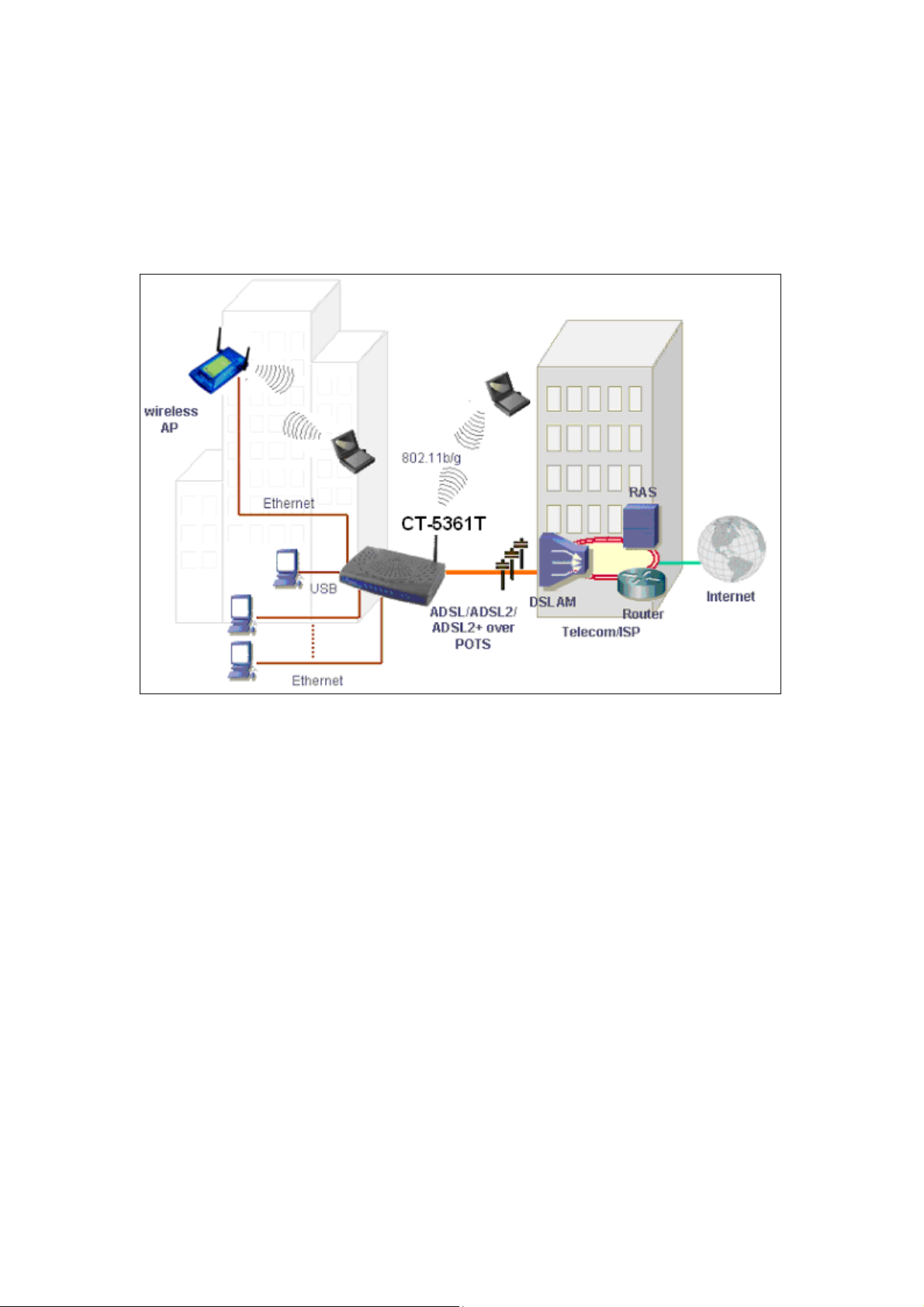
1.2 Application
The following diagram depicts the application of the device on a wireless network.
6
Page 8

1.3 Front Panel LED Indicators
The front panel LED indicators are shown in the picture below and followed by an
explanation in the table below.
LED Color Mode Function
Green On The router is powered up.
Off The router is powered down.
POWER
LAN
4x~1x
WLAN
USB
Red On POST (Power On Self Test) failure (not bootable) or
Device malfunction.
A malfunction is any error of internal sequence or state
that will prevent the device from connecting to the
DSLAM or passing customer data. This may be
identified at various times such after power on or
during operation through the use of self testing or in
operations which result in a unit state that is not
expected or should not occur.
Green On An Ethernet Link is established.
Off An Ethernet Link is not established.
Green Blink Data transmitting or receiving over LAN.
Green On The wireless module is ready and idle.
Off The wireless module is not installed.
Green Blink Data transmitting or receiving over WLAN.
Green On A USB link is established.
Off A USB link is not established.
Green Blink Data transmitting or receiving over USB.
7
Page 9

ADSL
Green On DSL good sync
Off Modem power off
Green Blink Flashing Green = DSL attempting sync
Flashing at 2 Hz with a 50% duty cycle when trying to
detect carrier signal
Flashing at 4 Hz with a 50% duty cycle when the carrier
has been detected and the modem is trying to train.
Green On IP connected and no traffic detected. If an IP or PPPoE
session is dropped due to an idle timeout, the light will
remain green if an ADSL connection is still present.
Off Modem power off, modem in bridged mode or ADSL
connection not present. Also, if an IP or PPPoE session
is dropped for any reason, other than an idle timeout,
INTERNET
the light is turned off.
Green Blink IP connected and IP Traffic is passing thru the device
(either direction)
Red On Device attempted to become IP connected and failed
(no DHCP response, no PPPoE response, PPPoE
authentication failed, no IP address from IPCP, etc.)
The light will turn red when it attempts to reconnect
and DHCP or PPPoE fails.
8
Page 10
Chapter 2 Installation
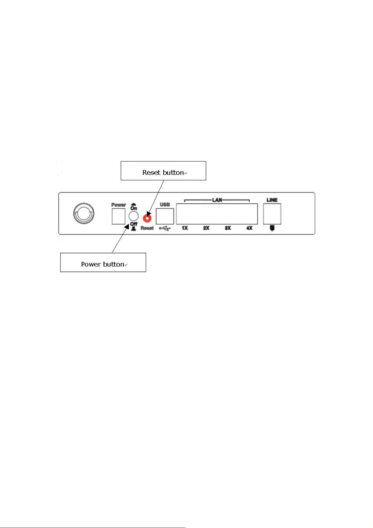
2.1 Hardware Installation
In the rear panel, there is a reset button. To load the factory default settings, hold
the reset button down for at least 5 seconds.
Follow the instructions below to complete the hardware connections.
Connection to LINE port
If you wish to connect both the router and a telephone, connect the LINE port to a
POTS splitter with a RJ11 connection cable.
Connection to LAN port
To connect to a hub or PC, use a RJ45 cable. You can connect the router to up to four
LAN devices. The ports are auto-sensing MDI/X and either straight-through cable
or crossover cable can be used.
Connection to USB port
Connect the USB port to a PC with a standard USB cable.
9
Page 11

Connection to Power
Connect the Power jack to the shipped power cord. Attach the power adapter to
the wall outlet or other AC source.
After all connections have been made, press the power-switch in to turn the device
on. After power on, the router performs a self-test. Wait for a few seconds until the
test is finished, then the router will be ready to operate.
Caution 1: If the router fails to power up, or it malfunctions, first verify that the
power supply is connected correctly. Then power it on again. If the
problem persists, contact our technical support engineers.
Caution 2: Before servicing or disassembling this equipment always disconnect all
power cords and telephone lines from the wall outlet.
10
Page 12
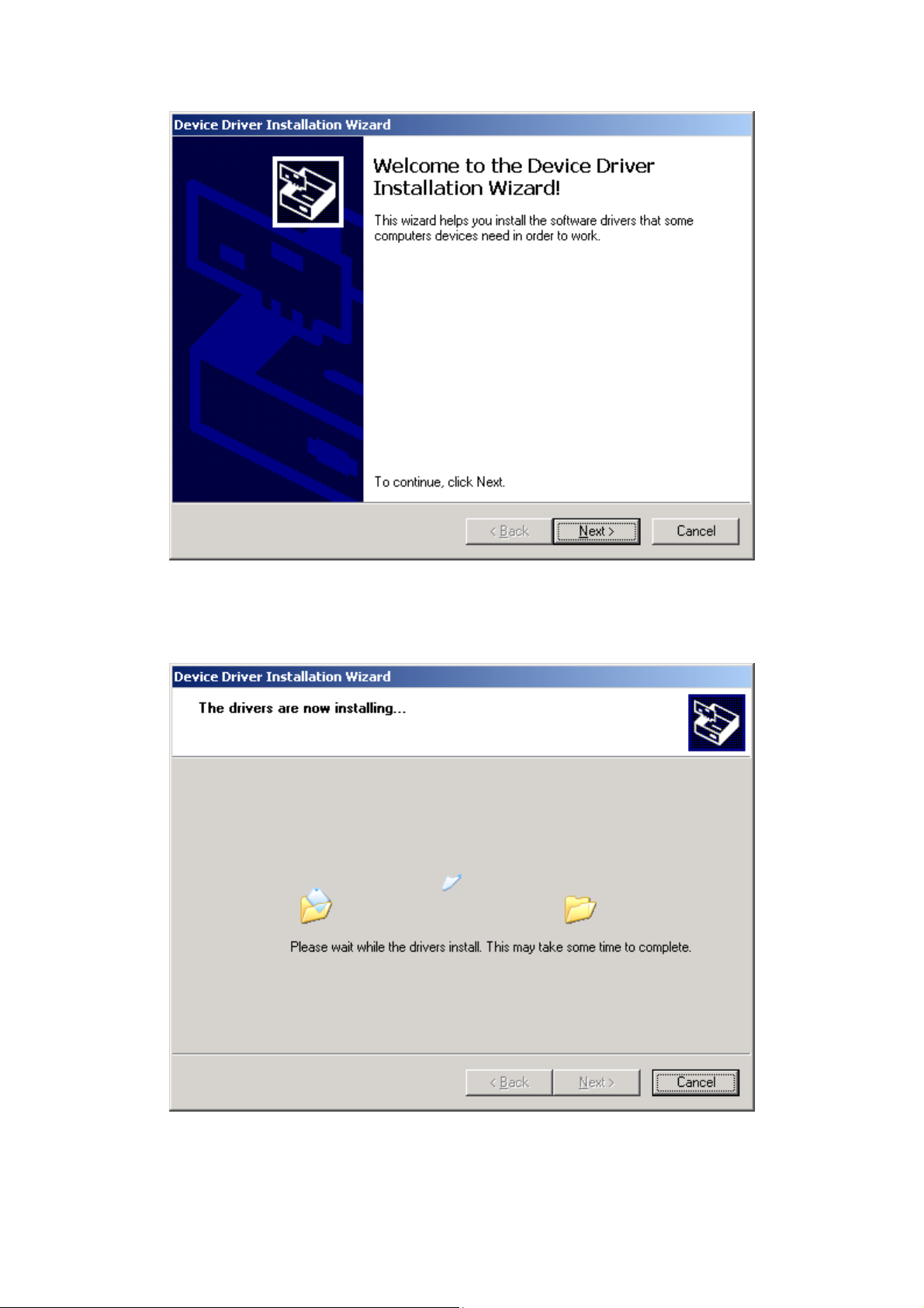
2.2 USB Device Driver Auto-run Installation
Before you connect your router’s USB cable to you r PC, you m u st l oad the A DS L USB
drivers. The auto-run USB driver installation supports Win ME, Win 98, Win 2000,
Win XP (32 bit) and Vista (32 bit). For those using Windows XP 64 bit, the driver
needs to be installed manually (please see section 2.3 below for details), and the
driver is also enclosed on the CD-ROM.
To connect the router to a PC using the USB interface, you need to use a standard
USB cable and install the USB interface software. Follow the steps below:
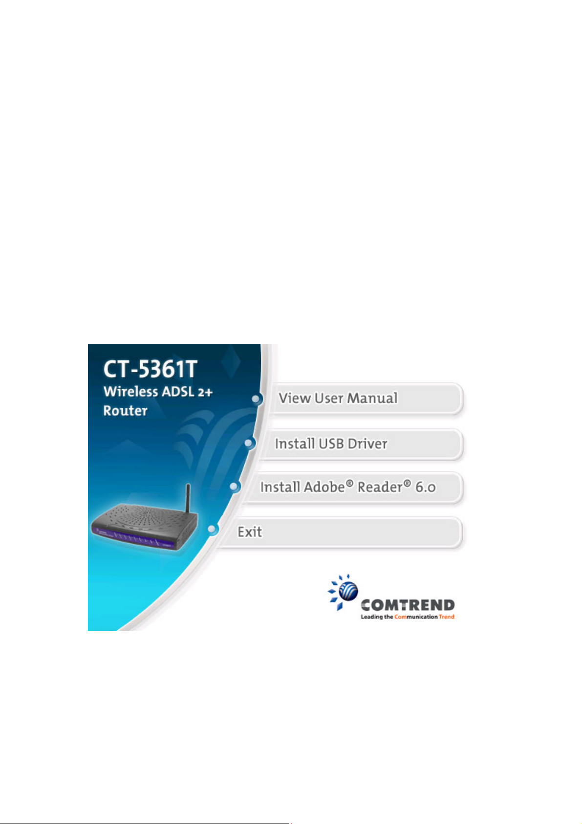
STEP 1: Insert the Installation disk and select the Install USB Driver option.
STEP 2: The following screen will be displayed. Click the Next button to continue.
11
Page 13
STEP 3: When the screen displays as below, wait until the drivers are fully installed.
STEP 4: Click the Finish button, when the screen displays as below.
12
Page 14
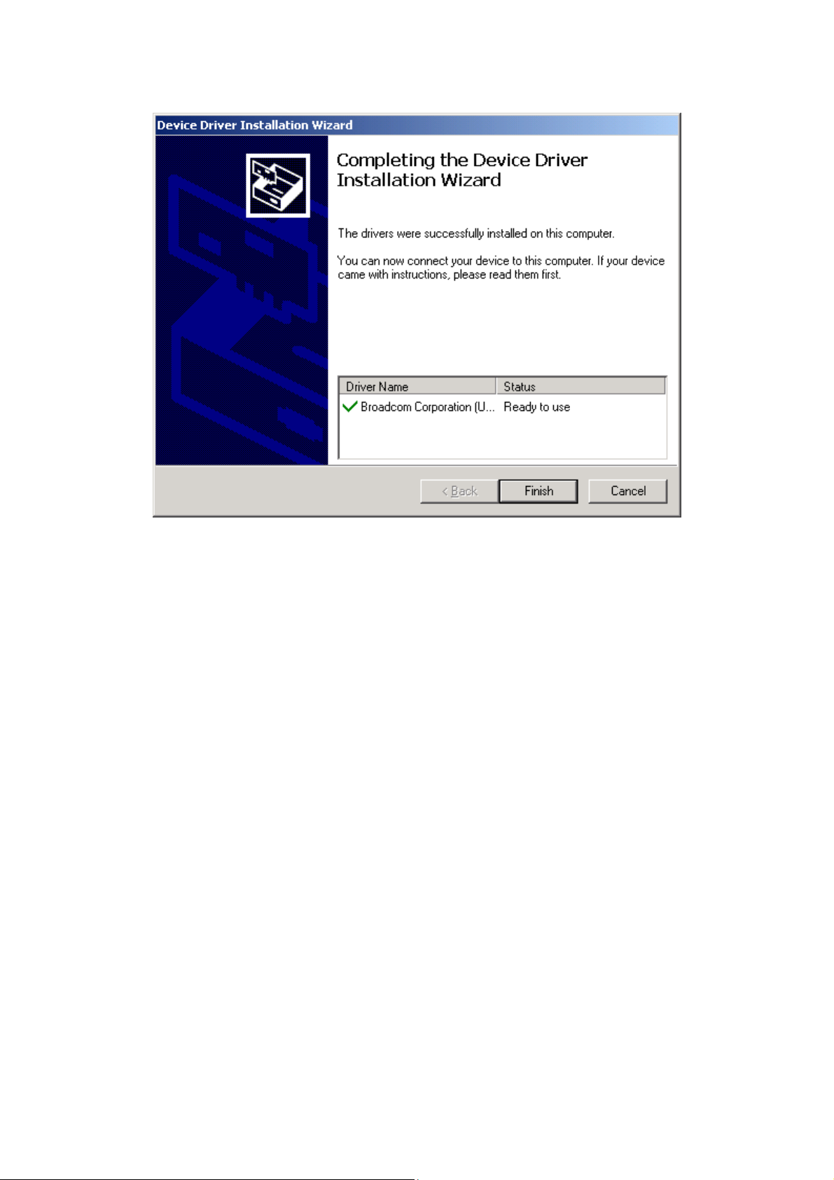
STEP 5: Installation is complete.
13
Page 15

2.3 USB Driver Manual Installation(64bit OS)
Before you connect your router’s USB cable to you r PC, you m u st l oad the A DS L USB
drivers. This manual USB driver installation supports Windows XP 64 bit.
To connect the router to a PC using the USB interface, you need to use a standard
USB cable and install the USB interface software. Follow the steps below:
STEP 1: Connect the USB router to the PC by plugging the flat connector of a
standard USB cable into your PC, and plugging the square connector into
the router. The screen will display as below:
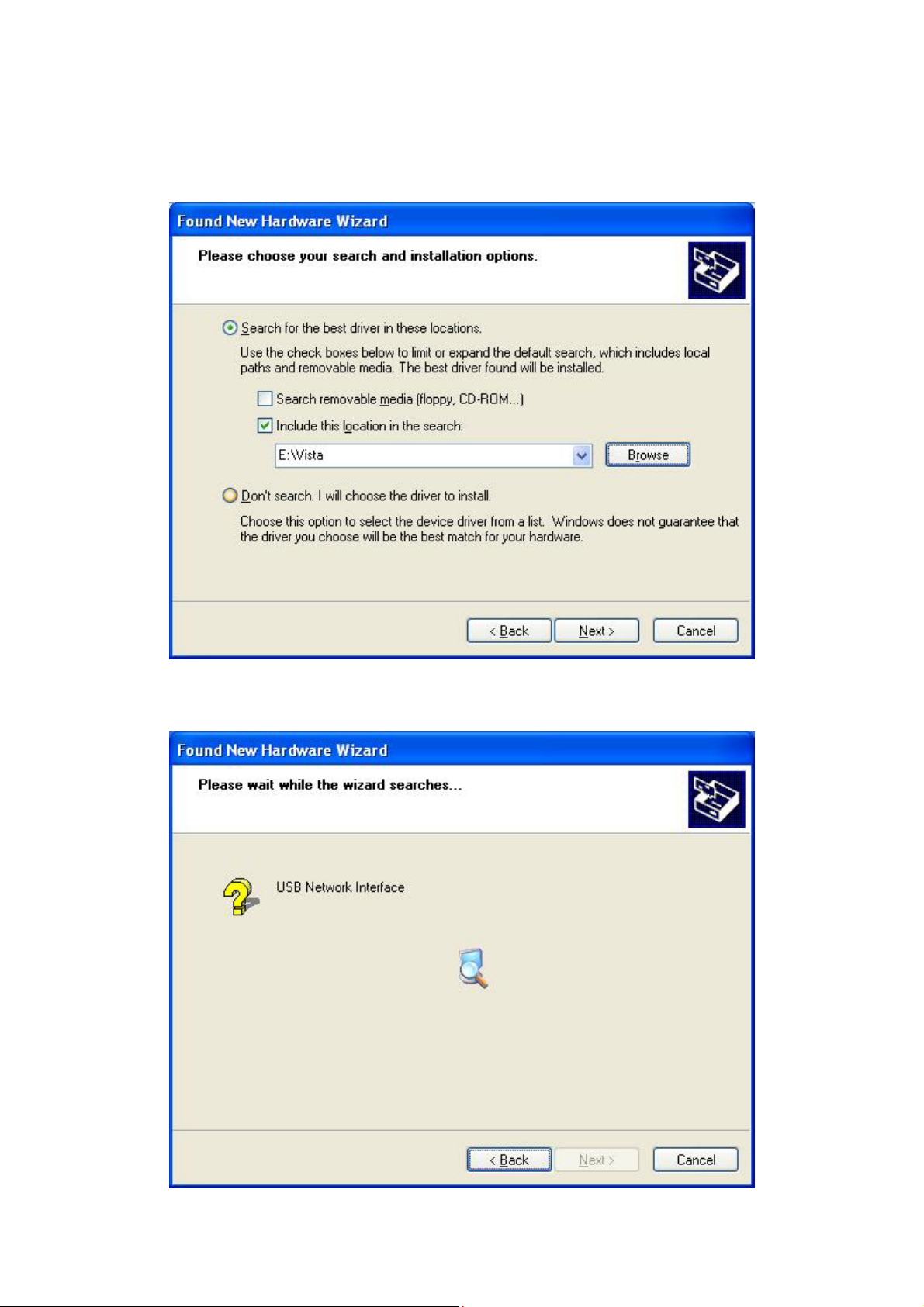
STEP 2: When the screen displays as below, select install from a list of specific
location (Advanced) and click the Next button.
14
Page 16
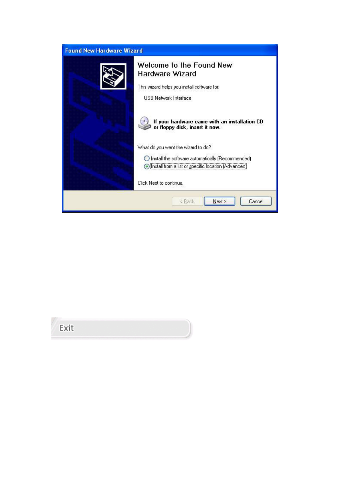
Note: This screen won’t be displayed if the USB Driver has been previously
un/installed.
STEP 3: If you are installing the software from a disk, insert the disk.
Note: When the auto-run screen pops up click Exit and continue with the manual
installation process (see below).
15
Page 17
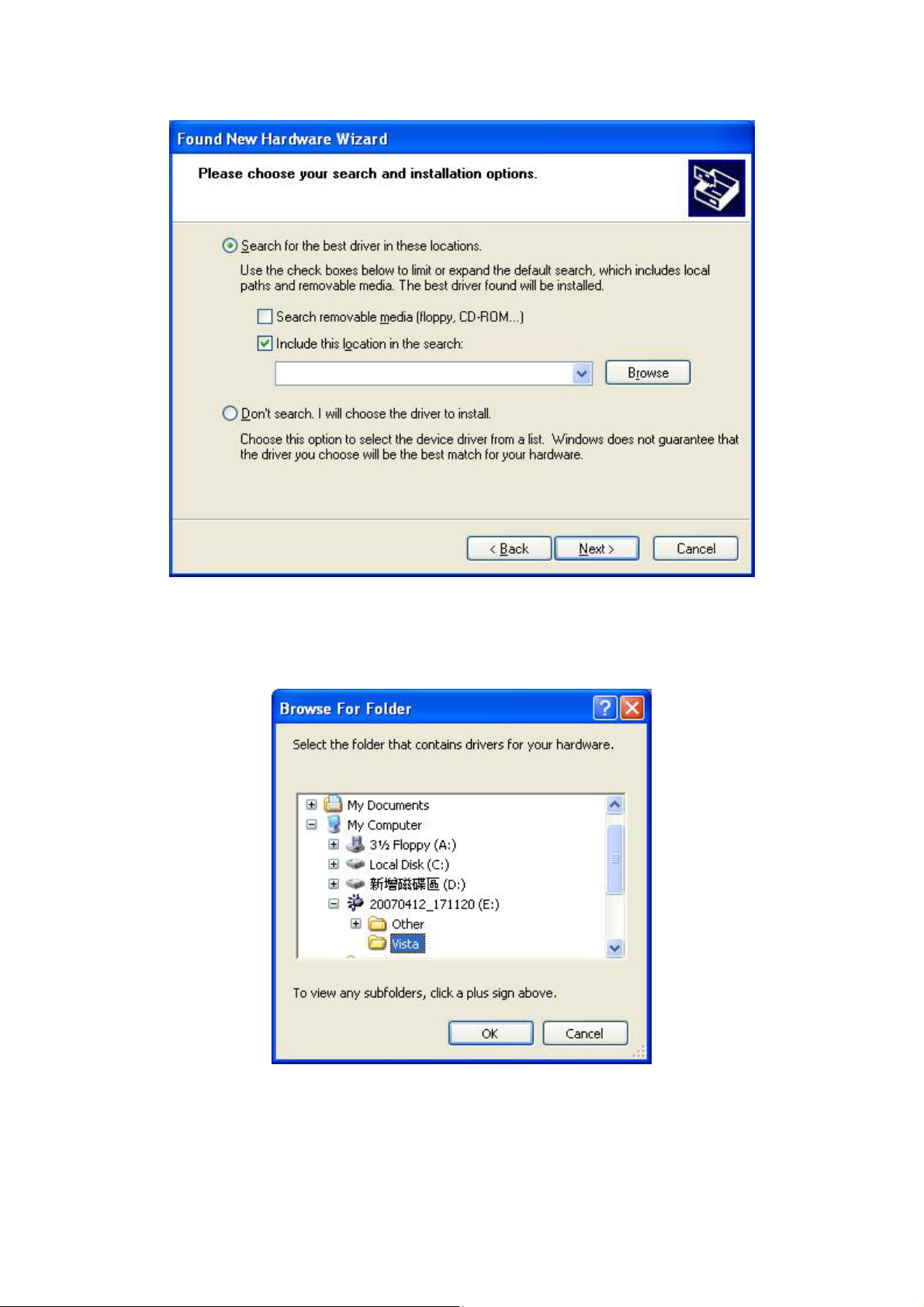
STEP 4: Select the location of the file using the Browse button. Normally, the file
is on the CD-ROM shipped with the device.
STEP 5: Locate the Vista folder, and click the OK button.
16
Page 18
STEP 6: When the screen displays as below, click the NEXT button.
17
Page 19
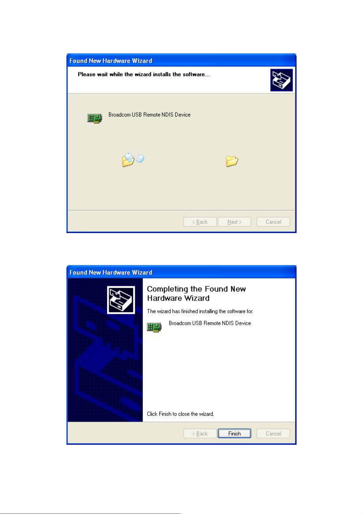
STEP 7: Click the Finish button, when the screen displays as below.
STEP 8: Installation is complete.
18
Page 20

Chapter 3 Login via the Web Browser
This section describes how to manage the router via a Web browser via the remote
end. You can use a web browser such as Microsoft Internet Explorer, or Netscape
Navigator. (The Web page is best viewed with Microsoft Internet Explorer 5.0 and
later): A unique default user account is assigned with user name root and password
12345. The user can change the default password later when logged in to the
device.
3.1 IP Address
The default IP address of the CT-5361T (LAN port) is 192.168.1.1. To configure the
CT-5361T for the first time, the configuration PC must have a static IP address
within the 192.168.1.x subnet. Follow the steps below to configure your PC IP
address to use subnet 192.168.1.x.
STEP 1: Right click on the Local Area Connection under the Network and Dial-Up
connection window and select Properties.
STEP 2: Enter the TCP/IP screen and change the IP address to the domain of
192.168.1.x/24.
19
Page 21
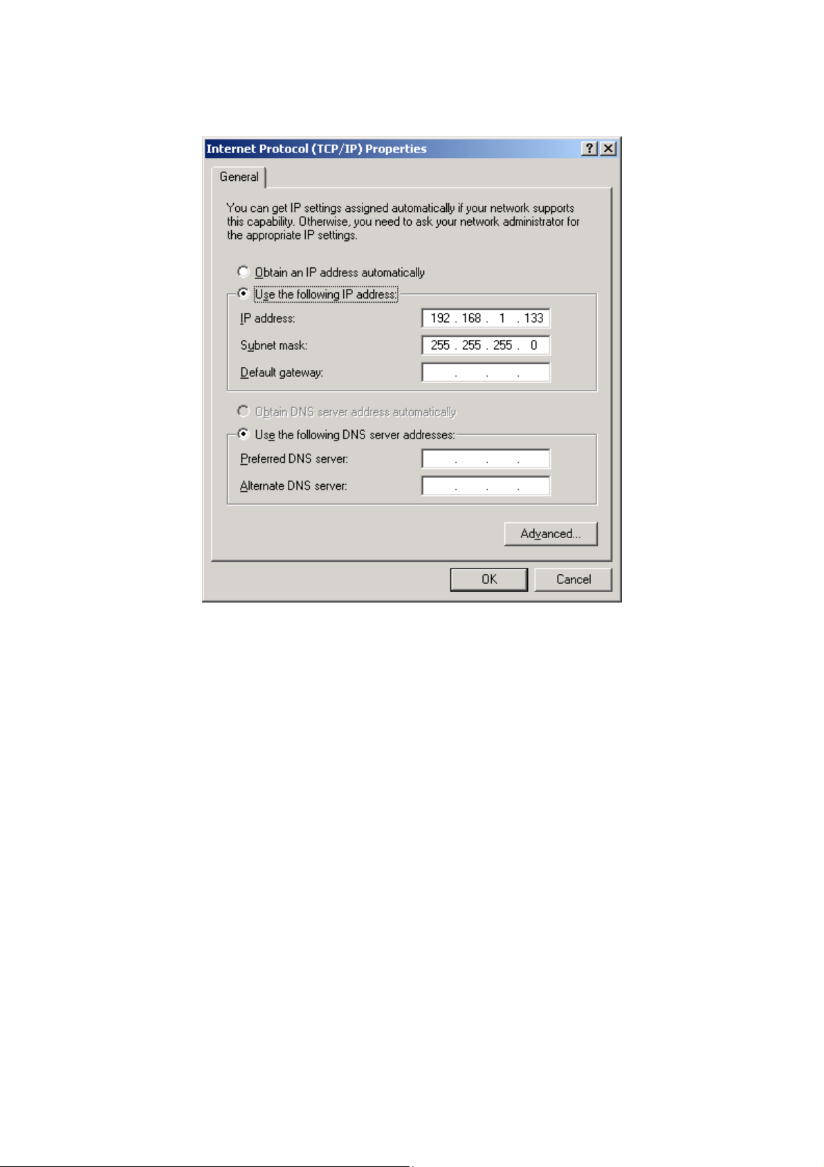
STEP 3: Click OK to submit the settings.
STEP 4: Start your Internet browser and type the IP address for the router
(192.168.1.1) in the Web address bar.
20
Page 22
3.2 Login Procedure
Perform the following steps to bring up the Web user interface and configure the
CT-5361T. To log on to the system from the Web browser, follow the steps below:
STEP 1: Start your Internet browser. Type the IP address for the router in the Web
address field. For example, if the IP address is 192.168.1.1, type
http://192.168.1.1
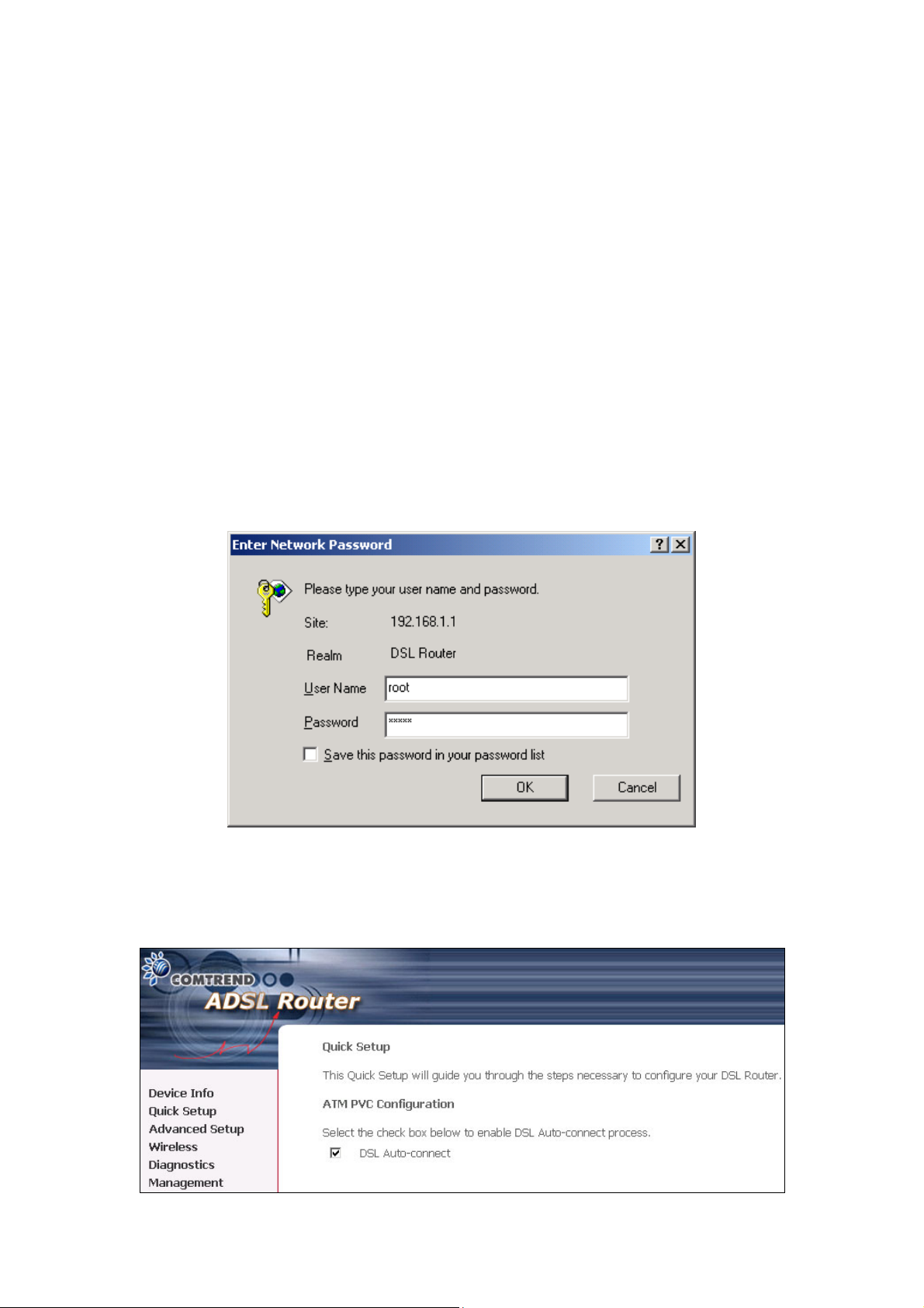
STEP 2: You will be prompted to enter your user name and password. Type root in
the user name and 12345 in the password field, and click OK. These
values can be changed later in the Web User Interface by selecting the
Management link.
STEP 3: After successfully logging in, you will reach the Quick Setup menu.
21
Page 23
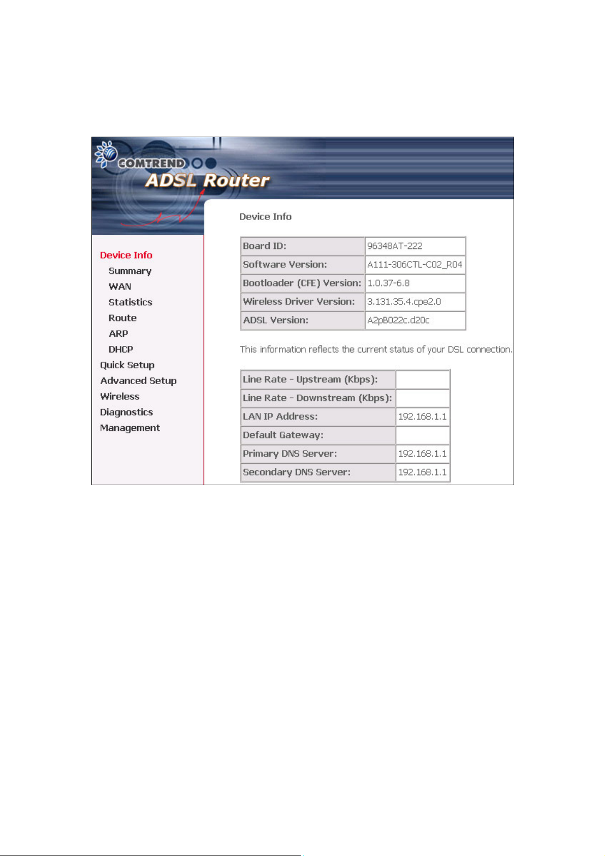
Shown here is the Device Info screen for your reference.
22
Page 24

3.3 Default Settings
During power on initialization, the CT-5361T initializes all configuration attributes to
default values. It will then read the configuration profile from the Permanent
Storage section on the flash memory. The default attributes are overridden when
identical attributes with different values are configured. The configuration profile
in Permanent Storage can be created via the Web user interface, telnet user
interface, or other management protocols. The factory default configuration can be
restored either by pushing the reset button for more than five seconds, or by
clicking the Restore Default Configuration option in the Restore Settings screen.
The following default settings are present when setting up the router for the first
time. The PC running the browser can be attached to the Ethernet.
z LAN port IP address: 192.168.1.1
z Local administrator account name: root
z Local administrator account password: 12345
z Local non- administrator account name: user
z Local non- administrator account password: user
z Remote WAN access: disabled
z Remote WAN access account name: support
z Remote WAN access account password: support
z NAT and firewall: enabled
z DHCP server on LAN interface: enabled
z WAN IP address: none
z Wireless Access enabled
z SSID: Comtrend
z Wireless authentication open (no authentication)
23
Page 25
Chapter 4 Device Info
After login, the Quick Setup screen appears as shown.
Note: The selections available on the left side of menu are based upon the
configured connection.
24
Page 26
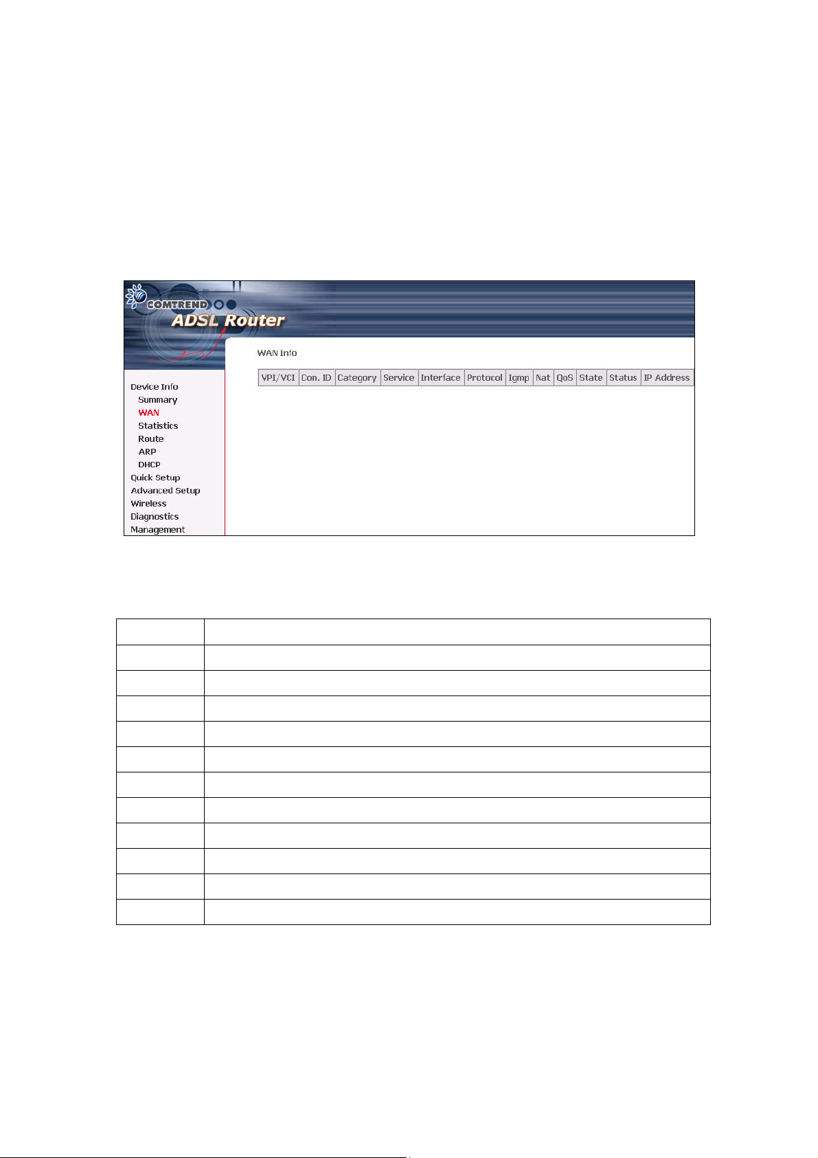
4.1 WAN
Click Device Info on the menu bar to display the WAN option. Then, click WAN on
the Device Info menu bar to display the configured PVC(s) and the status.
VPI/VCI Shows the values of the ATM VPI/VCI
Con. ID Shows the connection ID
Category Shows the ATM service classes
Service Shows the name for WAN connection
Interface Shows connection interfaces
Protocol Shows the connection type, such as PPPoE, PPPoA, etc.
IGMP Shows the state of the IGMP function
Nat Shows if the Network Address Translation(NAT) is enabled or disabled.
QoS Shows if IGMP IP QoS is enabled or disabled
State Shows the connection state of the WAN connection
Status Lists the status of DSL link
IP Address Shows IP address for WAN interface
25
Page 27

4.2 Statistics
Selection of the Statistics screen provides statistics for the Network Interface of LAN,
WAN, ATM and ADSL. All statistics screens are updated every 15 seconds.
26
Page 28
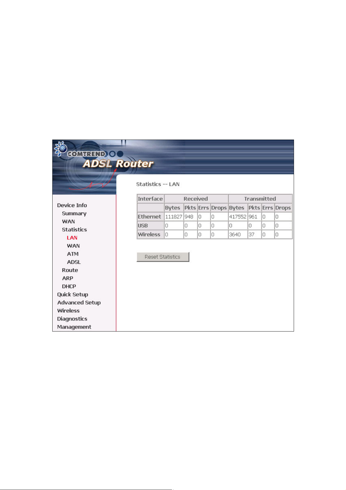
4.2.1 LAN Statistics
The Network Statistics screen shows the interface statistics for Ethernet, USB and
Wireless interfaces. (The Network Statistics screen shows the interface statistics for
the LAN interface. This provides byte transfer, packet transfer, Error and Drop
statistics for the LAN interface.)
27
Page 29
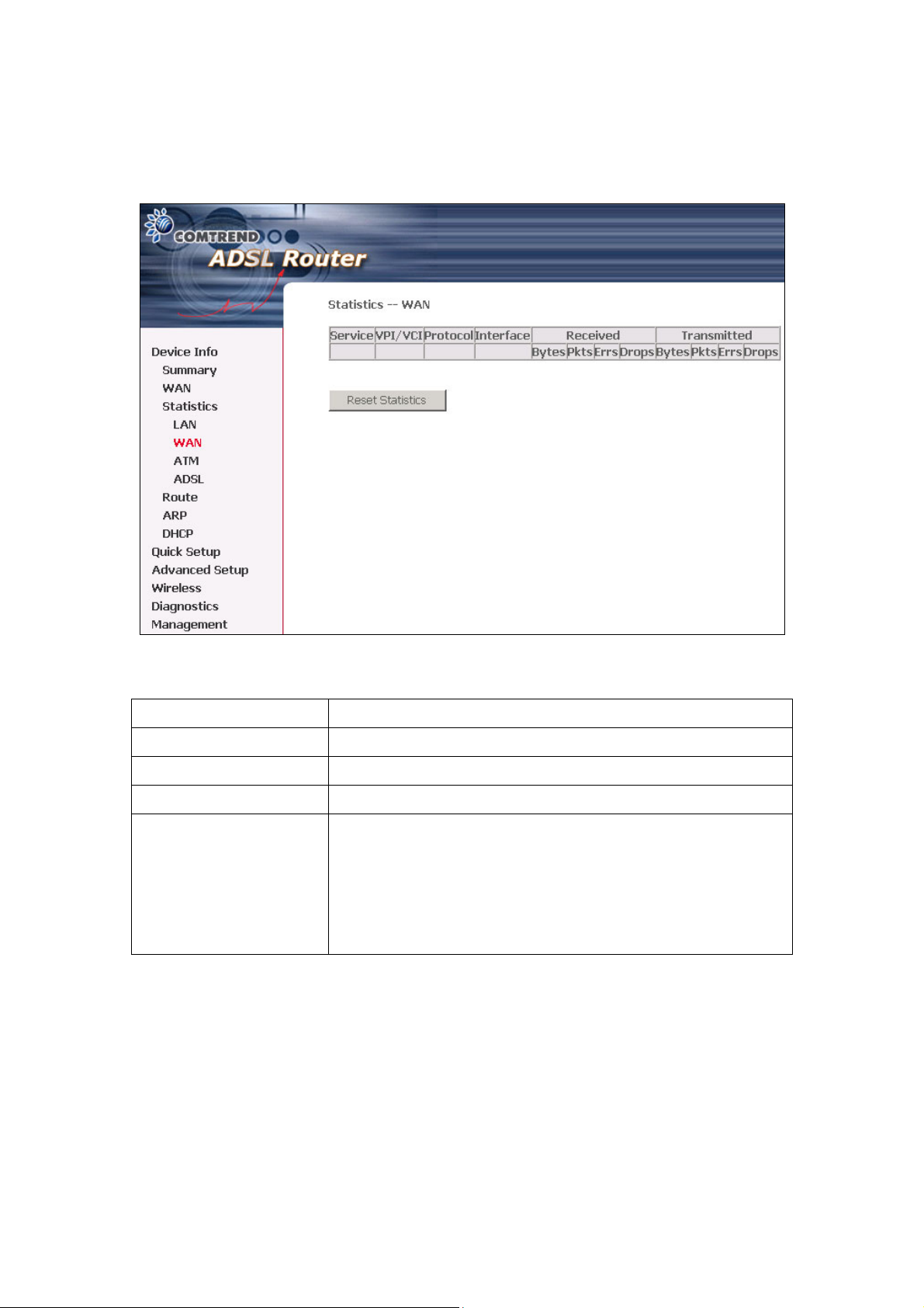
4.2.2 WAN Statistics
Service Shows the service type
VPI/VCI Shows the values of the ATM VPI/VCI
Protocol Shows the connection type, such as PPPoE, PPPoA, etc.
Interface Shows connection interfaces
Received/Transmitted
- Bytes
- Pkts
- Errs
- Drops
Number of Bytes Received/Transmitted
Number of packets Received/Transmitted
Number of errored packets Received/Transmitted
Number of dropped packets Received/Transmitted
28
Page 30
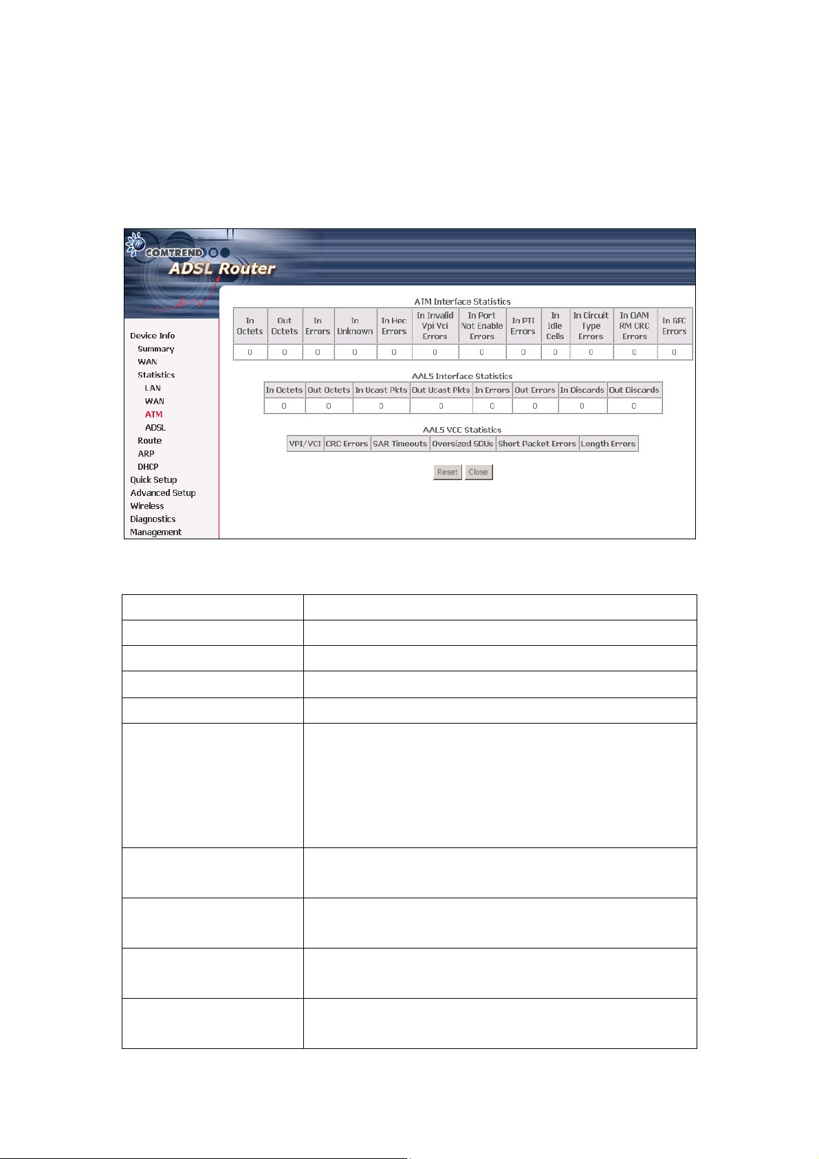
4.2.3 ATM statistics
The following figure shows the ATM statistics screen.
ATM Interface Statistics
Field Description
VPI/VCI Shows the values of the ATM VPI/VCI
In Octets Number of received octets over the interface
Out Octets Number of transmitted octets over the interface
In Errors Number of cells dropped due to uncorrectable HEC errors
In Unknown Number of received cells discarded during cell header
validation, including cells with unrecognized VPI/VCI
values, and cells with invalid cell header patterns. If
cells with undefined PTI values are discarded, they are
also counted here.
In Hec Errors Number of cells received with an ATM Cell Header HEC
error
In Invalid Vpi Vci Errors Number of cells received with an unregistered VCC
address
In Port Not Enable Errors Number of cells received on a port that has not been
enabled
In PTI Errors Number of cells received with an ATM header Payload
Type Indicator (PTI) error
29
Page 31

In Idle Cells Number of idle cells received
In Circuit Type Errors Number of cells received with an illegal circuit type
In Oam RM CRC Errors Number of OAM and RM cells received with CRC errors
In GFC Errors Number of cells received with a non-zero GFC
ATM AAL5 Layer Statistics over ADSL interface
Field Description
In Octets Number of received AAL5/AAL0 CPCS PDU octets
Out Octets Number of AAL5/AAL0 CPCS PDU octets transmitted
In Ucst Pkts Number of received AAL5/AAL0 CPCS PDU passed to a
higher-layer
Out Ucast Pkts Number of received AAL5/AAL0 CPCS PDU received from a
higher layer for transmission
In Errors Number of received AAL5/AAL0 CPCS PDU in error. The types
of errors counted include CRC-32 errors.
Out Errors Number of received AAL5/AAL0 CPCS PDU that could not be
transmitted due to errors.
In Discards Number of received AAL5/AAL0 CPCS PDU discarded due to an
input buffer overflow condition.
Out Discards This field is not currently used
A TM AAL5 L AYER STATISTICS FOR EACH VCC OVER ADSL INTERFACE
Field Description
CRC Errors Number of PDUs received with CRC-32 errors
SAR TimeOuts Number of partially re-assembled PDUs which were discarded
because they were not fully re-assembled within the required
period of time. If the re-assembly time is not supported
then, this object contains a zero value.
Over Sized SDUs Number of PDUs discarded because the corresponding SDU
was too large
Short Packets Errors Number of PDUs discarded because the PDU length was less
than the size of the AAL5 trailer
Length Errors Number of PDUs discarded because the PDU length did not
match the length in the AAL5 trailer
30
Page 32

4.2.4 ADSL Statistics
The following figure shows the ADSL Network Statistics screen. Within the ADSL
Statistics window, a bit Error Rate Test can be started using the ADSL BER Test
button. The Reset button resets the statistics.
31
Page 33

Field Description
Mode Line Coding format, that can be selected G.dmt, G.lite,
T1.413, ADSL2
Type Channel type Interleave or Fast
Line Coding Trellis On/Off
Status Lists the status of the DSL link
Link Power State Link output power state.
SNR Margin (dB) Signal to Noise Ratio (SNR) margin
Attenuation (dB) Estimate of average loop attenuation in the downstream
direction.
Output Power (dBm) Total upstream output power
Attainable Rate (Kbps) The sync rate you would obtain.
Rate (Kbps) Current sync rate.
Super Frames Total number of super frames
Super Frame Errors Number of super frames received with errors
RS Words Total number of Reed-Solomon code errors
RS Correctable Errors Total Number of RS with correctable errors
RS Uncorrectable Errors Total Number of RS words with uncorrectable errors
HEC Errors Total Number of Header Error Checksum errors
OCD Errors Total Number of out-of-cell Delineation errors
LCD Errors Total number of Loss of Cell Delineation
Total ES: Total Number of Errored Seconds
Total SES: Total Number of Severely Errored Seconds
Total UAS: Total Number of Unavailable Seconds
32
Page 34

4.2.5 Route
Choose Route to display the routes that the route information has learned.
4.2.6 ARP
Click ARP to display the ARP information.
33
Page 35

4.2.7 DHCP
Click DHCP to display the DHCP information.
34
Page 36

Chapter 5 Quick Setup
The Quick Setup allows the user to configure the ADSL router for DSL connectivity
and Internet access. It also guides the user though the WAN network setup first
and then the LAN interface setup. You can either manually customize the router or
follow the online instruction to set up the router.
The CT-5361T ADSL router supports the following five network operating modes
over an ATM PVC WAN interface.
z PPP over Ethernet (PPPoE)
z PPP over ATM (PPPoA)
z MAC Encapsulated Routing (MER)
z IP over ATM (IPoA)
z Bridging
The following configuration considerations apply:
z The WAN network operating mode operation depends on the service provider’s
configuration on the Central Office side and Broadband Access Server for the
PVC
z If the service provider provides PPPoE service, then the connection selection
depends on whether the LAN-side device (typically a PC) is running a PPPoE
client or whether the CT-5361T is to run the PPPoE client. The CT-5361T can
support both cases simultaneously.
z If some or none of the LAN-side devices do not run PPPoE client, then select
PPPoE. If every LAN-side device is running a PPPoE client, then select Bridge
In PPPoE mode, CT-5361T also supports pass-through PPPoE sessions from the
LAN side while simultaneously running a PPPoE client fro non-PPPoE LAN
devices. NAT and firewall are always enabled when PPPoE mode is selected, but
they can be enabled or disabled by the user when MER or IPoA is selected, NAT
and firewall are always disabled when Bridge mode is selected.
z Depending on the network operating mode, and whether NAPT and firewall are
enabled or disabled, the main panel will display or hide the NAPT/Firewall menu.
For instance, at initial setup, the default network operating mode is Bridge.
The main panel will not show the NAPT and Firewall menu.
35
Page 37

Note: Up to sixteen PVC profiles can be configured and saved on the flash memory.
To activate a particular PVC profile, you need to navigate all the Quick Setup pages
until the last summary page, then click on the Finish button and reboot the system.
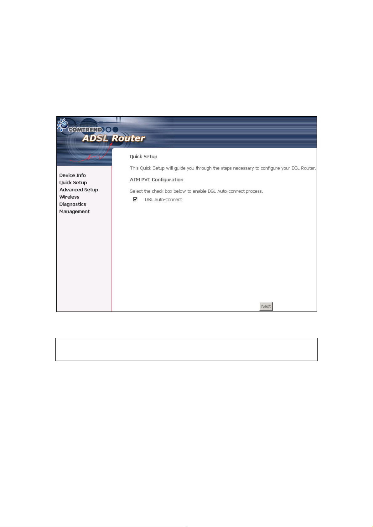
5.1 Auto Quick Setup
The auto quick setup requires the ADSL link to be up. The ADSL router will
automatically detect the PVC. You only need to follow the online instructions that
you are prompted.
1. Select Quick Setup to display the DSL Quick Setup screen.
2. Click Next to start the setup process. Follow the online instructions to complete
the setting. This procedure will skip some processes like PVC index, or
encapsulation.
3. After the settings are complete, you can use the ADSL service.
36
Page 38

5.2 Manual Quick Setup
STEP 1: Click Quick Setup and un-tick the DSL Auto-connect checkbox to enable
manual configuration of the connection type.
Un-tick this checkbox to enable manual setup and display
the following screen.
STEP 2: Enter the Virtual Path Identifier (VPI) and Virtual Channel Identifier (VCI).
Select Enable Quality Of Service if required. Click Next.
37
Page 39

STEP 3: Choosing different connection types pops up different settings requests.
Enter appropriate settings that are requested by your service provider. The
following descriptions state each connection type setup separately. Select
Enable 802.1q (by ticking the box) if required, and input a number for the
VLAN ID. Click on “Next” to go to next step.
38
Page 40

5.2.1 PPP over ATM (PPPoA) and PPP over Ethernet (PPPoE)
1. Select the PPP over ATM (PPPoA) or PPP over Ethernet (PPPoE) radio
button and click Next. The following screen appears:
PPP USERNAME/PPP PASSWORD
Give “PPP Username”, “PPP Password” and “PPPoE Service Name”, then select the
“Authentication Method” (AUTO/PAP/CHAP/MSCHAP). Please contact your ISP for
the information. The WEB user interface allows a maximum of 256 characters in the
PPP user name and a maximum of 32 characters in PPP password.
Encapsulation Mode
Choosing different connection types provides different encapsulation modes.
z PPPoA- VC/MUX, LLC/ENCAPSULATION
z PPPoE- LLC/SNAP BRIDGING, VC/MUX
z MER- LLC/SNAP-BRIDGING, VC/MUX
z IPoA- LLC/SNAP-ROUTING, VC MUX
z Bridging- LLC/SNAP-BRIDGING, VC/MUX
Disconnect if no activity
The CT-5361T can be configured to disconnect if there is no activity for a period of
time by selecting the Dial on demand check box. When the checkbox is ticked, you
need to enter the inactivity timeout period. The timeout period ranges from 1
minute to 4320 minutes.
39
Page 41

PPP IP Extension
The PPP IP Extension is a special feature deployed by some service providers.
Unless your service provider specially requires this setup, do not select it.
The PPP IP Extension supports the following conditions:
z Allows only one PC on the LAN
z The public IP address assigned by the remote side using the PPP/IPCP protocol
is actually not used on the WAN PPP interface. Instead, it is forwarded to the
PC’s LAN interface through DHCP. Only one PC on the LAN can be connected to
the remote, since the DHCP server within the ADSL router has a single IP
address to assign to a LAN device.
z NAPT and firewall are disabled when this option is selected.
z The ADSL router becomes the default gateway and DNS server to the PC
through DHCP using the LAN interface IP address.
z The ADSL router extends the IP subnet at the remote service provider to the
LAN PC. That is, the PC becomes a host belonging to the same IP subnet.
z The ADSL router bridges the IP packets between WAN and LAN ports, unless
the packet is addressed to the router’s LAN IP address.
Use Static IP Address
Unless your service provider specially requires this setup, do not select it.
If selected, enter your static IP address.
Enable PPP Debug Mode
Enable the PPPoE debug mode. The system will put more PPP connection information
in System Log. But this is for debug, please don't enable in normal usage.
2. Click Next to display the screen on the following page.
Enable IGMP Multicast checkbox: Tick the checkbox to enable IGMP multicast
(proxy). IGMP (Internet Group Membership Protocol) is a protocol used by IP hosts
to report their multicast group memberships to any immediately neighboring
multicast routers.
40
Page 42

Enable WAN Service checkbox: Tick this item to enable the ATM service. Untick
it to stop the ATM service.
Service Name: This is user-defined.
3. After entering your settings, select Next. The following screen appears. This
page allows the user to configure the LAN interface IP address, subnet mask and
DHCP server. If the user would like this ADSL router to assign dynamic IP address,
DNS server and default gateways to other LAN devices, select the button Enable
DHCP server on the LAN to enter the starting IP address and end IP address and
DHCP leased time.
41
Page 43

The Device Setup page allows the user to configure the LAN interface IP address and
DHCP server. If the user would like this ADSL router to assign dynamic IP
addresses, DNS server and default gateway to other LAN devices, select the radio
box Enable DHCP server on the LAN to enter the starting IP address and end IP
address and DHCP lease time. This configures the router to automatically assign IP
addresses, default gateway address and DNS server addresses to each of your PCs.
Note 1: Enable DHCP Server Relay will not display if Firewall is enabled in the
previous step.
Note 2: The router’s default IP address is 192.168.1.1 and the default private
address range provided by the ISP server in the router is 192.168.1.2 through
192.168.1.254.
4. The following screen will be displayed. To enable the wireless function, select the
box (by clicking on it) and input the SSID. Then, click Next.
5. Click Next to display the WAN Setup-Summary screen that presents the entire
configuration summary. Click Save/Reboot if the settings are correct. Click
Back if you wish to modify the settings.
42
Page 44

6. After clicking Save/Reboot, the router will save the configuration to the flash
memory, and reboot. The Web UI will not respond until the system is brought up
again. After the system is up, the Web UI will refresh to the Device Info page
automatically. The CT-5361T is ready for operation and the LED indicators display
as described in the LED description tables (subsection 1.3).
43
Page 45

5.2.2 MAC Encapsulation Routing (MER)
To configure MER, do the following.
1. Select Quick Setup and click Next.
2. Enter the PVC Index provided by the ISP and click Next.
3. Select the MAC Encapsulation Routing (MER) radio button, and click Next. The
following screen appears.
Enter information provided to you by your ISP to configure the WAN IP settings.
Notice: DHCP can be enabled for PVC in MER mode if Obtain an IP address
automatically is chosen. Changing the default gateway or the DNS effects the
whole system. Configuring them with static values will disable the automatic
assignment from DHCP or other WAN connection.
If you configure static default gateway over this PVC in MER mode, you must enter
the IP address of the remote gateway in the “Use IP address”. The “Use WAN
interface” is optional.
The ISP should provide the values that must be entered in the entry fields.
44
Page 46

4. Click Next to display the following screen.
Enable NAT checkbox: If the LAN is configured with a private IP address, the user
should select this checkbox. The NAT submenu on the left side main panel will be
displayed after reboot. The user can then configure NAT-related features after the
system comes up. If a private IP address is not used on the LAN side, this checkbox
should be de-selected to free up system resources for better performance. When
the system comes back after reboot, the NAT submenu will not be displayed on the
left main panel.
Enable Firewall checkbox: If the firewall checkbox is selected, the Security
submenu on the left side main panel will be displayed after system reboot. The
user can then configure firewall features after the system comes up. If firewall is
not used, this checkbox should be de-selected to free up system resources for better
performance. When system comes back after reboot, the Security submenu will
not be displayed on the left main panel.
Enable IGMP Multicast: Tick the checkbox to enable IGMP multicast (proxy).
IGMP (Internet Group Membership Protocol) is a protocol used by IP hosts to report
their multicast group memberships to any immediately neighboring multicast
routers.
Enable WAN Service: Tick the checkbox to enable the WAN service. If this item
is not selected, you will not be able to use the WAN service.
Service Name: This is User-defined.
45
Page 47

5. Upon completion, click Next. The following screen appears.
The Device Setup page allows the user to configure the LAN interface IP address and
DHCP server. If the user would like this ADSL router to assign dynamic IP
addresses, DNS server and default gateway to other LAN devices, select the radio
box Enable DHCP server on the LAN to enter the starting IP address and end IP
address and DHCP lease time. This configures the router to automatically assign IP
addresses, default gateway address and DNS server addresses to each of your PCs.
Note 1: Enable DHCP Server Relay will not display if Firewall is enabled in the
previous step.
Note 2: The router’s default IP address is 192.168.1.1 and the default private
address range provided by the ISP server in the router is 192.168.1.2 through
192.168.1.254.
Note: Ethernet interface (and the wireless LAN interface on the CT-5361T) share
the same subnet since they are bridged within the router.
46
Page 48

6. After entering your settings, select Next to display the following screen. The
WAN Setup-Summary screen presents the entire configuration summary. Click
Save/Reboot if the settings are correct. Click Back if you wish to modify the
settings.
7. The following screen will be displayed. To enable the wireless function, select
the box (by clicking on it) and input the SSID. Then, click Next.
The following screen will be displayed.
After clicking Save/Reboot, the router will save the configuration to the flash
memory, and reboot. The Web UI will not respond until the system is brought up
again. After the system is up, the Web UI will refresh to the Device Info page
automatically. The CT-5361T is ready for operation and the LED indicators display
as described in the LED description tables (subsection 1.3).
47
Page 49

5.2.3 IP Over ATM
To configure IP Over ATM,
1. Select Quick Setup and click Next.
2. Enter the PVC Index and click Next.
3. Type the VPI and VCI values provided by the ISP and click Next.
4. Select the IP over ATM (IPoA) radio button and click Next. The following screen
appears.
Notice that DHCP is not supported over IPoA. The user must enter the IP address
or WAN interface for the default gateway setup, and the DNS server addresses
provided by the ISP.
5. Click Next. The following screen appears.
48
Page 50

Enable NAT checkbox
If the LAN is configured with a private IP address, the user should select this
checkbox. The NAT submenu on the left side main panel will be displayed after
reboot. The user can then configure NAT-related features after the system comes
up. If a private IP address is not used on the LAN side (i.e. the LAN side is using a
public IP), this checkbox should be de-selected. When the system comes back
after reboot, the NAT submenu will not be displayed on the left main panel.
Enable Firewall checkbox
If the firewall checkbox is selected, the Security submenu on the left side main panel
will be displayed after system reboot. The user can then configure firewall features
after the system comes up. If firewall is not used, this checkbox should be
de-selected to free up system resources for better performance. When system
comes back after reboot, the Security submenu will not be displayed on the left
main panel.
6. Click Next to display the following screen. The Device Setup page allows the
user to configure the LAN interface IP address and DHCP server if the user would
like this ADSL router to assign dynamic IP addresses, DNS server and default
gateway to other LAN devices. Select the button Enable DHCP server on the LAN to
enter the starting IP address and end IP address and DHCP lease time.
49
Page 51

The user must configure the IP Address and the Subnet Mask. To use the DHCP
service on the LAN, select the Enable DHCP server checkbox, and enter the Start
IP addresses, the End IP address and DHCP lease time. This configures the router
to automatically assign IP addresses, default gateway address and DNS server
addresses to each of your PCs.
Note 1: Enable DHCP Server Relay will not display if Firewall is enabled in the
previous step.
Note 2: The router’s default IP address is 192.168.1.1 and the default private
address range provided by the ISP server in the router is 192.168.1.2 through
192.168.1.254.
7. The following screen will be displayed. To enable the wireless function, select the
box (by clicking on it) and input the SSID. Then, click Next.
The following screen will be displayed.
50
Page 52

8. After clicking Save/Reboot, the router will save the configuration to the flash
memory, and reboot. The Web UI will not respond until the system is brought up
again. After the system is up, the Web UI will refresh to the Device Info page
automatically. The CT-5361T is ready for operation and the LED indicators display
as described in the LED description tables (subsection 1.3).
51
Page 53

5.2.4 Bridging
Select the bridging mode. To configure Bridging, do the following.
1. Select Quick Setup and click Next.
2. Enter the PVC Index and click Next.
3. Type in the VPI and VCI values provided by the ISP and click Next.
4. Select the Bridging radio button and click Next. The following screen appears.
To use the bridge service, tick the checkbox, Enable Bridge Service, and enter
the service name.
5. Click the Next button to continue. Enter the IP address for the LAN interface.
The default IP address is 192.168.1.1. The LAN IP interface in bridge operating
mode is needed for local users to manage the ADSL router. Notice that there is
no IP address for the WAN interface in bridge mode, and the remote technical
support cannot access the ADSL router.
52
Page 54

6. The following screen will be displayed. To enable the wireless function, select the
box (by clicking on it) and input the SSID. Then, click Next.
The following screen will be displayed.
The WAN Setup-Summary screen presents the entire configuration summary.
Click Save/Reboot if the settings are correct. Click Back if you wish to modify the
settings.
53
Page 55

Chapter 6 Advanced Setup
This chapter explains: WAN, LAN, Routing, DSL and Port Mapping……
Note: Shown below for your reference are the available menu options for each
different configuration.
This screenshot is for MER and IPoA encapsulations.
This screenshot is for PPPoE and PPPoA encapsulations.
54
Page 56

This screenshot is for Bridge encapsulation.
55
Page 57

6.1 WAN
VlanID
Please reference subsection 4.1 for further information.
• This function means one can add an 802.1Q VLAN tag on
PPPoE/MER or Bridge mode.
It means the packets are sent to WAN and a specific VlanID
(802.1Q tag) will be added in the Ethernet header. The VlanID
shows which 802.1Q tag will be added.
56
Page 58

6.2 LAN
Configure the DSL Router IP Address and Subnet Mask for LAN interface. Save
button only saves the LAN configuration data. Save/Reboot button saves the LAN
configuration data and reboots the router to make the new configuration effective.
IP Address: Enter the IP address for the LAN port.
Subnet Mask: Enter the subnet mask for the LAN port.
Enable IGMP Snooping: Enable /Disable the function that is IGMP Snooping.
Standard Mode: In standard mode, as in all prior releases, multicast traffic will
flood to all bridge ports when there is no client subscribes to any multicast group –
even when IGMP snooping is enabled.
Blocking Mode: In blocking mode, the multicast data traffic will be blocked and not
flood to all bridge ports when there is no client subscription to any multicast group.
To configure a secondary IP address for the LAN port, click the box as shown below.
57
Page 59

IP Address: Enter the secondary IP address for the LAN port.
Subnet Mask: Enter the secondary subnet mask for the LAN port.
58
Page 60

6.3 NAT
To display the NAT function, you need to enable the NAT feature in the WAN Setup.
6.3.1 Virtual Servers
Virtual Server allows you to direct incoming traffic from WAN side (identified by
Protocol and External port) to the Internal server with private IP address on the LAN
side. The Internal port is required only if the external port needs to be converted to
a different port number used by the server on the LAN side. A maximum 32 entries
can be configured.
To add a Virtual Server, simply click the Add button. The following will be displayed.
59
Page 61

Select a Service
Or
Custom Server
User should select the service from the list.
Or
User can enter the name of their choice.
Server IP Address Enter the IP address for the server.
External Port Start Enter the starting external port number (when you select
Custom Server). When a service is selected the port ranges
are automatically configured.
External Port End Enter the ending external port number (when you select
Custom Server). When a service is selected the port ranges
are automatically configured.
Protocol User can select from: TCP, TCP/UDP or UDP.
Internal Port Start Enter the internal port starting number (when you select
Custom Server). When a service is selected the port ranges
are automatically configured
Internal Port End Enter the internal port ending number (when you select
Custom Server). When a service is selected the port ranges
are automatically configured.
60
Page 62

6.3.2 Port Triggering
Some applications require that specific ports in the Router’s firewall be opened for
access by the remote parties. Port Trigger dynamically opens up the ‘Open Ports’ in
the firewall when an application on the LAN initiates a TCP/UDP connection to a
remote party using the ‘Triggering Ports’. The Router allows the remote party from
the WAN side to establish new connections back to the application on the LAN side
using the ‘Open Ports’. A maximum 32 entries can be configured.
To add a Trigger Port, simply click the Add button. The following will be displayed.
61
Page 63

Select an Application
User should select the application from the list.
Or Custom Application
Trigger Port Start Enter the starting trigger port number (when you select
Trigger Port End Enter the ending trigger port number (when you select
Trigger Protocol User can select from: TCP, TCP/UDP or UDP.
Open Port Start Enter the starting open port number (when you select
Open Port End Enter the ending open port number (when you select
Open Protocol User can select from: TCP, TCP/UDP or UDP.
Or User can enter the name of their choice.
custom application). When an application is selected the
port ranges are automatically configured.
custom application). When an application is selected the
port ranges are automatically configured.
custom application). When an application is selected the
port ranges are automatically configured.
custom application). When an application is selected the
port ranges are automatically configured.
6.3.3 DMZ Host
The DSL router will forward IP packets from the WAN that do not belong to any of
the applications configured in the Virtual Servers table to the DMZ host computer.
Enter the computer’s IP address and click “Apply” to activate the DMZ host.
Clear the IP address field and click “Apply” to deactivate the DMZ host.
62
Page 64

6.3.4 ALG
SIP ALG is Application layer gateway. If the user has an IP phone(SIP) or VoIP
gateway(SIP) behind the ADSL router, the SIP ALG can help VoIP packet
passthrough the router (NAT enabled).
Note: SIP (Session Initiation Protocol, RFC3261) is the protocol of choice for most
VoIP (Voice over IP) phones to initiate communication. This ALG is only valid for SIP
protocol running on UDP port 5060.
63
Page 65

6.4 Security
To display the Security function, you need to enable the firewall feature in the WAN
Setup.
6.4.1 IP Filtering
IP filtering allows you to create a filter rule to identify outgoing/incoming IP traffic
by specifying a new filter name and at least one condition below. All of the specified
conditions in this filter rule must be satisfied for the rule to take effect. Click
‘Save/Apply’ to save and activate the filter.
Outgoing
Note: The default setting for Outgoing is Accepted.
To add a filtering rule, simply click the Add button. The following screen will be
displayed.
64
Page 66

Filter Name Type a name for the filter rule.
Protocol User can select from: TCP, TCP/UDP, UDP or
ICMP.
Source IP address Enter source IP address.
Source Subnet Mask Enter source subnet mask.
Source Port (port or port:port) Enter source port number.
Destination IP address Enter destination IP address.
Destination Subnet Mask Enter destination subnet mask.
Destination port (port or port:port) Enter destination port number.
65
Page 67

Incoming
Note: The default setting for Incoming is Blocked.
To add a filtering rule, simply click the Add button. The following screen will be
displayed.
To configure the parameters, please reference Outgoing
66
table above.
Page 68

6.4.2 Parental Control
Parental control: allows parents, schools, and libraries to set access times for
Internet use.
To add a parental control, simply click the Add button. The following screen will be
displayed.
Username: Input Internet access user name
MAC: Set the MAC address to access the Internet
Mon, Tue, Wed, Thu, Fri, Sat, Sun: Set which days that will have block
restrictions to Internet access
Start, End Blocking Time: Set Internet block start and stop time
67
Page 69

6.4.3 MAC Filtering
Mac Filtering is only available when Bridging PVC is configured.
Each network device has a unique MAC address. You can block or forward the
packets based on the MAC addresses. The MAC Filtering Setup screen allows
setting up the MAC filtering policy and the MAC filtering rules. MAC Filtering is only
effective on ATM PVCs configured in Bridge mode.
The policy FORWARDED means that all MAC layer frames will be FORWARDED
except those matching with any of the specified rules in the following table.
BLOCKED means that all MAC layer frames will be BLOCKED except those
matching with any of the specified rules in the following table. The default is
FORWARD; you change by clicking the Change Policy button.
Choose Add or Remove to configure MAC filtering rules. The following screen
pops up when you click Add. Create a filter to identify the MAC layer frames by
specifying at least one condition below. If multiple conditions are specified, all of
them take effect. Click Apply to save and activate the filter.
68
Page 70

Option Description
Protocol type PPPoE, IPv4, IPv6, AppleTalk, IPX, NetBEUI, IGMP
Destination MAC Address Define the destination MAC address
Source MAC Address Define the source MAC address
Frame Direction: Select a direction of the frame
WAN Interface Selects the interface that the MAC filter rule(s) will be
applied. Only the WAN interface that is configured for
bridged can be selected.
69
Page 71

6.5 Quality of Service
To d is p l a y t he Qo S f u nc ti o n , you need to enable the QoS feature in the WAN Setup.
Choose Add to configure network traffic classes. The following screen will be
displayed:
70
Page 72

Traffic Class Name Enter name for traffic class.
Assign ATM Transmit Priority Select Low, Medium or High.
Mark IP Precedence Select between 0-7. The lower the digit
shows the higher the priority.
Mark IP Type Of Service Select either: Normal Service, Minimize
Cost, Maximize Reliability, Maximize
Throughput, Minimize Delay
Mark 802.1p if 802.1q is enabled on WAN Select between 0-7. The higher the
digit shows the higher the priority.
SET-1
Physical LAN Port Select between ENET(1-4), USB,
Wireless and Wireless_Guest.
Protocol User can select from: TCP, TCP/UDP,
UDP or ICMP.
Source IP Address Enter the source IP address.
71
Page 73

Source Subnet Mask Enter the subnet mask for the source IP
address.
Source Port (port or port:port) Enter source port number or port
range.
Destination IP address Enter destination IP address.
Destination Subnet Mask Enter destination subnet mask.
Destination port (port or port:port) Enter destination port number or port
range.
SET-2
802.1p Priority Select between 0-7. The lower the digit
shows the higher the priority
If the Enable Differentiated Service Configuration box is ticked (i.e. selected)
the following screen will be displayed:
72
Page 74

The additional Items are explained here.
Assign Differentiated Services
Code Point (DSCP) Mark
The selected Code Point gives the
corresponding priority to the packets that
satisfies the rules set below.
Source MAC Address A packet belongs to SET-1, if a binary-AND of
its source MAC address with the Source MAC
Mask is equal to the binary-AND of the
Source MAC Mask and this field.
Source MAC Mask This is the mask used to decide how many
bits are checked in Source MAC Address.
Destination MAC Address A packet belongs to SET-1 then the result
that the Destination MAC Address of its
header binary-AND to the Destination MAC
Mask must equal to the result that this field
binary-AND to the Destination MAC Mask.
Destination MAC Mask This is the mask used to decide how many
bits are checked in Destination MAC Address.
73
Page 75

6.6 Routing
The Routing dialog box allows you to configure Default gateway, Static Route and
RIP.
6.6.1 Default Gateway
If ‘Enable Automatic Assigned Default Gateway’ checkbox is selected, this
router will accept the first received default gateway assignment from one of the
PPPoA, PPPoE or MER/DHCP enabled PVC(s). If the checkbox is not selected, enter
the static default gateway AND/OR a WAN interface. Click ‘Save/Apply’ button to
save it.
NOTE: If changing the Automatic Assigned Default Gateway from unselected to
selected, You must reboot the router to get the automatic assigned default gateway.
74
Page 76

6.6.2 Static Route
Choose Static Route to display the Static Route screen. The Static Route screen
lists the configured static routes, and allows configuring static routes. Choose Add
or Remove to configure the static routes.
To add static route, click the Add button to display the following screen. Enter the
destination network address, subnet mask, gateway AND/OR available WAN
interface then click Save/Apply to add the entry to the routing table.
75
Page 77

6.6.3 RIP
To activate RIP for the device, select the 'Enabled' radio button for Global RIP Mode.
To configure an individual interface, select the desired RIP version and operation,
followed by placing a check in the 'Enabled' checkbox for the interface. Click the
'Save/Apply' button to save the configuration, and to start or stop RIP based on the
Global RIP mode selected.
76
Page 78

6.7 DNS
6.7.1 DNS Server
If 'Enable Automatic Assigned DNS' checkbox is selected, this router will accept the
first received DNS assignment from one of the PPPoA, PPPoE or MER/DHCP enabled
PVC(s) during the connection establishment. If the checkbox is not selected, enter
the primary and optional secondary DNS server IP addresses. Click 'Save' button to
save the new configuration. You must reboot the router to make the new
configuration effective.
77
Page 79

6.7.2 Dynamic DNS
The Dynamic DNS service allows you to alias a dynamic IP address to a static
hostname in any of the many domains, allowing your DSL router to be more easily
accessed from various locations on the Internet.
To add a dynamic DNS service, simply click the Add button. The following screen will
be displayed:
78
Page 80

D-DNS provider Select a dynamic DNS provider from the list.
Hostname Enter the name for the dynamic DNS server.
Interface Select the interface from the list.
Username Enter the username for the dynamic DNS server.
Password Enter the password for the dynamic DNS server.
79
Page 81

6.8 DSL
To access the DSL settings, first click On Advanced Setup and then click on DSL.
The DSL Settings dialog box allows you to select an appropriate modulation mode.
Option Description
G.dmt Enabled Sets G.Dmt if you want the system to use G.Dmt mode.
G.Lite Enabled Sets G.Lite if you want the system to use G.Lite mode.
T1.413 Enabled Sets the T1.413 if you want the system to use only T1.413
mode.
ADSL2 Enabled The device can support the functions of the ADSL2.
AnnexL Enabled The device can support/enhance the long loop test.
ADSL2+ Enabled The device can support the functions of the ADSL2+.
AnnexM DISABLED Covers a higher “upstream” data rate version, by making use of
some of the downstream channels.
Inner Pair Reserved only
Outer Pair Reserved only
Bitswap Enable Allows bitswaping function
80
Page 82

SRA Enable Allows seamless rate adaptation
6.9 Port Mapping
Port Mapping supports multiple port to PVC and bridging groups. Each group will
perform as an independent network. To support this feature, you must create
mapping groups with appropriate LAN and WAN interfaces using the Add button.
The Remove button will remove the grouping and add the ungrouped interfaces to
the Default group.
As shown below, when you tick the Enable virtual ports on, all of the LAN interfaces
will be grouped together as a default.
To add a port mapping group, simply click the Add button.
81
Page 83

To create a group from the list, first enter the group name and then select from the
available interfaces on the list.
Automatically Add Clients With the Following DHCP Vendor IDs:
Add support to automatically map LAN interfaces including Wireless and USB to
PVC's using DHCP vendor ID (option 60). The local DHCP server will decline and
send the requests to a remote DHCP server by mapping the appropriate LAN
interface. This will be turned on when PortMapping is enabled.
There are 4 PVCs (0/33, 0/36, 0/37, 0/38). 0/33 is for PPPoE and the others are for
IP setup-box (video).
The LAN interfaces are ETH1, ETH2, ETH3, ETH4, USB Wireless and Wireless_Guest.
Port mapping configuration are:
1. Default: ETH1, ETH2, ETH3, ETH4, USB Wireless and Wireless_Guest.
82
Page 84

2. Video: nas_0_36, nas_0_37 and nas_0_38. The DHCP vendor ID is "Video".
The CPE's DHCP server is running on "Default". And ISP's DHCP server is running on
PVC 0/36. It is for setup-box use only.
In the LAN side, PC can get IP address from CPE's DHCP server and access Internet
via PPPoE (0/33).
If the setup-box was connected with interface "ETH1" and send a DHCP request with
vendor id "Video", CPE's DHCP server will forward this request to ISP's DHCP server.
And CPE will change the port mapping configuration automatically. The port
mapping configuration will become:
1. Default: ETH2, ETH3, ETH4, USB Wireless and Wireless_Guest.
2. Video: nas_0_36, nas_0_37, nas_0_38 and ETH1.
83
Page 85

6.10 Certificate
A certificate is a public key, attached with its owner’s information (company name,
server name, personal real name, contact e-mail, postal address, etc) and digital
signatures. There will be one or more digital signatures attached on the certificate,
indicating that these signers have verified that the owner information of this
certificate is correct.
6.10.1 Local
Click Create Certificate Request to generate a certificate signing request. The
certificate signing request can be submitted to the vendor/ISP/ITSP to apply for a
certificate. Some information must be included in the certificate signing request.
Actually, your vendor/ISP/ITSP will ask you to provide the information they require
and to provide the information in the format they regulate. The explanation for each
column in the following table is only for reference.
84
Page 86

Certificate Name A user-defined name for the certificate.
Common Name Usually, it is the fully qualified domain name for the
machine.
Organization Name The exact legal name of your organization. Do not
abbreviate.
State/Province Name The state or province where your organization is located. It
cannot be abbreviated.
Country/Region Name The two-letter ISO abbreviation for your country.
Click Apply to generate a private key and a certificate signing request.
This page is used to paste the certificate content and the private key provided by
your vendor/ISP/ITSP.
85
Page 87

6.10.2 Trusted CA
CA is the abbreviation for Certificate Authority. CA is a part of the X.509 system. It
is itself a certificate, attached with the owner information of this certificate authority.
But its purpose is not to do encryption/decryption. Its purpose is to sign and issue
certificates; in order to prove the owner information of that certificate is correct.
Click Import Certificate to paste the certificate content of your trusted CA.
Generally speaking, the certificate content will be provided by your vendor/ISP/ITSP
and is used to authenticate the Auto-Configuration Server (ACS) that the CPE will
connect to.
86
Page 88

Chapter 7 Wireless
The Wireless dialog box allows you to enable the wireless capability, hide the access
point, set the wireless network name and restrict the channel set.
7.1 Wireless Basic Screen
The Basic option allows you to configure basic features of the wireless LAN interface.
You can enable or disable the wireless LAN interface, hide the network from active
scans, set the wireless network name (also known as SSID) and restrict the channel
set based on country requirements.
Click Apply to configure the basic wireless options.
87
Page 89

Option Description
Enable Wireless A checkbox that enables or disables the wireless LAN
interface. When selected, the Web UI displays Hide Access
point, SSID, and County settings. The default is Enable
Wireless.
Hide Access Point Select Hide Access Point to protect ADSL router access point
from detection by wireless active scans. If you do not want
the access point to be automatically detected by a wireless
station, this checkbox should be de-selected.
The station will not discover this access point. To connect a
station to the available access points, the station must
manually add this access point name in its wireless
configuration.
In Windows XP, go to the Network>Programs function to view
all of the available access points. You can also use other
software programs such as NetStumbler to view available
access points.
SSID Sets the wireless network name. SSID stands for Service Set
Identifier. All stations must be configured with the correct
SSID to access the WLAN. If the SSID does not match, that
user will not be granted access.
The naming conventions are: Minimum is one character and
maximum number of characters: 32 bytes.
88
Page 90

BSSID The BSSID is a 48bit identity used to identify a particular BSS
(Basic Service Set) within an area. In Infrastructure BSS
networks, the BSSID is the MAC (Medium Access Control)
address of the AP (Access Point) and in Independent BSS or ad
hoc networks, the BSSID is generated randomly.
Country A drop-down menu that permits worldwide and specific
national settings. Each county listed in the menu enforces
specific regulations limiting channel range:
z US= worldwide
z Japan=1-14
z Jordan= 10-13
z Israel= 1-13
7.1.1 Security
Security options include authentication and encryption services based on the wired
equivalent privacy (WEP) algorithm. WEP is a set of security services used to
protect 802.11 networks from unauthorized access, such as eavesdropping; in this
case, the capture of wireless network traffic. When data encryption is enabled,
secret shared encryption keys are generated and used by the source station and the
destination station to alter frame bits, thus avoiding disclosure to eavesdroppers.
802.11 supports two subtypes of network authentication services: open system and
shared key. Under open system authentication, any wireless station can request
authentication. The system that needs to authenticate with another wireless
station sends an authentication management frame that contains the identity of the
sending station. The receiving station then sends back a frame that indicates
whether it recognizes the identity of the sending station.
Under shared key authentication, each wireless station is assumed to have
received a secret shared key over a secure channel that is independent from 802.11
wireless network communications channel.
The following screen appears when Security is selected. The Security page allows
you to configure security features of the wireless LAN interface. You can set the
network authentication method, selecting data encryption, specify whether a
network key is required to authenticate to this wireless network and specify the
encryption strength.
89
Page 91

Click Apply to configure the wireless security options.
Option Description
Network
Authentication
It specifies the network authentication. When this checkbox is selected, it specifies
that a network key be used for authentication to the wireless network. If the
Network Authentication (Shared mode) checkbox is not shared (that is, if open
system authentication is used), no authentication is provided. Open system
authentication only performs identity verifications.
Different authentication type pops up different settings requests.
Choosing 802.1X, enter RADIUS Server IP address, RADIUS Port, and RADIUS key.
Also, enable WEP Encryption and the Encryption Strength.
90
Page 92

Select the Current Network Key and enter 13 ASCII characters or 26 hexadecimal
digits for 128-bit encryption keys and enter 5 ASCII characters or 10 hexadecimal
digits for 64-bit encryption keys.
Choosing WPA, you must enter WPA Group Rekey Interval.
Choosing WPA-PSK, you must enter WPA Pre-Shared Key and Group Rekey
Interval.
91
Page 93

WEP
Encryption
Encryption
strength
It specifies that a network key is used to encrypt the data is sent over the network.
When this checkbox is selected, it enables data encryption and prompts the
Encryption Strength drop-down menu. Data Encryption (WEP Enabled) and
Network Authentication use the same key.
A session’s key strength is proportional to the number of binary bits comprising the
session key file. This means that session keys with a greater number of bits have a
greater degree of security, and are considerably more difficult to forcibly decode.
This drop-down menu sets either a 64 8-bit (5-ASCII character or 10-hexadecimal
character) or 128 8-bit (13-ASCII character or 26-hexadecimal character) key.
If you set a minimum 128-bit key strength, users attempting to establish a secure
communications channel with your server must use a browser capable of
communicating with a 128-bit session key.
The Encryption Strength settings do not display unless the network Authentication
(shared Mode) check box is selected.
92
Page 94

7.1.2 MAC Filter
This MAC Filter page allows access to be restricted/allowed based on a MAC address.
All NICs have a unique 48-bit MAC address burned into the ROM chip on the card.
When MAC address filtering is enabled, you are restricting the NICs that are allowed
to connect to your access point. Therefore, an access point will grant access to any
computer that is using a NIC whose MAC address is on its “allows” list.
Wi-Fi routers and access points that support MAC filtering let you specify a list of
MAC addresses that may connect to the access point, and thus dictate what devices
are authorized to access the wireless network. When a device is using MAC filtering,
any address not explicitly defined will be denied access.
MAC Restrict mode: Off- disables MAC filtering; Allow – permits access for the
specified MAC address; deny; reject access of the specified MAC address, then click
the SET button.
To delete an entry, select the entry at the bottom of the screen and then click the
Remove button, located on the right hand side of the screen.
To add a MAC entry, click Add and enter MAC address
After choosing the Add button, the following screen appears. Enter the MAC
address and click Apply to add the MAC address to the wireless MAC address filters.
93
Page 95

Option Description
MAC Restrict Mode Radio buttons that allow settings of;
Off: MAC filtering function is disabled.
Allow: Permits PCs with listed MAC addresses to connect to
the access point.
Deny: Prevents PCs with listed MAC from connecting to the
access point.
MAC Address Lists the MAC addresses subject to the Off, Allow, or Deny
instruction. The Add button prompts an entry field that
requires you type in a MAC address in a two-character,
6-byte convention: xx:xx:xx:xx:xx:xx where xx are
hexadecimal numbers. The maximum number of MAC
addresses that can be added is 60.
94
Page 96

7.1.3 Wireless Bridge
This page allows you to configure wireless bridge features of the wireless LAN
interface. You can select Wireless Bridge (also known as Wireless Distribution
System) to disable access point functionality. Selecting Access Point enables access
point functionality. Wireless bridge functionality will still be available and wireless
stations will be able to associate to the AP. Select Disabled in Bridge Restrict, which
disables wireless bridge restriction. Any wireless bridge will be granted access.
Selecting Enabled or Enabled (Scan) enables wireless bridge restriction. Only those
bridges selected in Remote Bridges will be granted access.
Option Description
AP Mode Access Point
Wireless Bridge
Bridge Restrict Enabled
Enabled (Scan)
Disabled
95
Page 97

7.1.4 Advanced
The Advanced page allows you to configure advanced features of the wireless LAN
interface. You can select a particular channel on which to operate, force the
transmission rate to a particular speed, set the fragmentation threshold, set the RTS
threshold, set the wakeup interval for clients in power-save mode, set the beacon
interval for the access point, set XPress mode and set whether short or long
preambles are used.
Click Apply to configure the advanced wireless options.
Option Description
AP Isolation Select On or Off. By enabling this feature, wireless
clients associated with the Access Point will be able to
connect to each other.
96
Page 98

Band The new amendment allows IEEE 802.11g units to fall
back to speeds of 11 Mbps, so IEEE 802.11b and IEEE
802.11g devices can coexist in the same network. The
two standards apply to the 2.4 GHz frequency band.
IEEE 802.11g creates data-rate parity at 2.4 GHz with
the IEEE 802.11a standard, which has a 54 Mbps rate at
5 GHz. (IEEE 802.11a has other differences compared to
IEEE 802.11b or g, such as offering more channels.)
Channel Drop-down menu that allows selection of a specific
channel.
Auto Channel Timer(min) Auto channel scan timer in minutes (0 to disable)
54g™ Rate Drop-down menu that specifies the following fixed rates:
Auto: Default. Uses the 11 Mbps data rate when
possible but drops to lower rates when necessary.
1 Mbps, 2Mbps, 5.5Mbps, or 11Mbps fixed rates. The
appropriate setting is dependent on signal strength.
Multicast Rate Setting multicast packet transmit rate.
Basic Rate Setting basic transmit rate.
Fragmentation Threshold A threshold, specified in bytes, that determines whether
packets will be fragmented and at what size. On an
802.11 WLAN, packets that exceed the fragmentation
threshold are fragmented, i.e., split into, smaller units
suitable for the circuit size. Packets smaller than the
specified fragmentation threshold value are not
fragmented.
Enter a value between 256 and 2346.
If you experience a high packet error rate, try to slightly
increase your Fragmentation Threshold. The value
should remain at its default setting of 2346. Setting
the Fragmentation Threshold too low may result in poor
performance.
RTS Threshold Request to Send, when set in bytes, specifies the packet
size beyond which the WLAN Card invokes its RTS/CTS
mechanism. Packets that exceed the specified RTS
threshold trigger the RTS/CTS mechanism. The NIC
transmits smaller packet without using RTS/CTS.
The default setting of 2347 (maximum length) disables
RTS Threshold.
97
Page 99

DTIM Interval Delivery Traffic Indication Message (DTIM), also known
as Beacon Rate. The entry range is a value between 1
and 65535. A DTIM is a countdown informing clients of
the next window for listening to broadcast and multicast
messages. When the AP has buffered broadcast or
multicast messages for associated clients, it sends the
next DTIM with a DTIM Interval value. AP Clients hear
the beacons and awaken to receive the broadcast and
multicast messages. The default is 1.
Beacon Interval The amount of time between beacon transmissions.
Each beacon transmission identifies the presence of an
access point. By default, radio NICs passively scan all
RF channels and listen for beacons coming from access
points to find a suitable access point.
Before a station enters power save mode, the station
needs the beacon interval to know when to wake up to
receive the beacon (and learn whether there are
buffered frames at the access point).
The entered value is represented in ms. Default is 100.
Acceptable entry range is 1 to 0xffff (65535)
Maximum Associated
Clients
Xpress
TM
Technology Xpress Technology is compliant with draft specifications
This is the maximum number of client allowed to
connect to the router.
of two planned wireless industry standards.
Wireless Media Extension Provides an interim QoS solution for 802.11 networks
until the release of 802.11e. WRAP (Wireless Robust
Authenticated Protocol) An encryption protocol in the
802.11i standard. WRAP is based upon the Offset
Codebook (OCB) mode of AES. WRAP is being replaced
with CCMP.
TM
54g
Mode Select the mode to 54g Auto for
the widest compatibility. Select the mode to
54g Performance for the fastest performance
among 54g certified equipment. Set
the mode to 54g LRS if you are experiencing
difficulty with legacy 802.11b equipment.
98
Page 100

54g Protection In Auto mode the router will use
RTS/CTS to improve 802.11g performance in
mixed 802.11g/802.11b networks. Turn
protection off to maximize 802.11g throughput
under most conditions.
Preamble Type Short preamble is intended for application where
maximum throughput is desired but it doesn’t cooperate
with the legacy.
Long preamble interoperates with the current 1 and 2
Mbit/s DSSS specification as described in IEEE Std
802.11-1999
Transmit Power The router will set different power output (by
percentage) according to this selection.
99
 Loading...