

Comtest Networks 4048 SYSTEM 5 User Manual
Model 4048 SYSTEM 5 Splitter Shelf Installation Guide
Copyright © 2009,
Comtest Networks Inc.
This guide provides the basic information required to install the Comtest Model 4048 SYSTEM 5 Splitter Shelf
on a 19” or 23” rack assembly.
Unpacking the 4048 shelf
Before opening the 4048 shipping box, carefully inspect for any signs of damage. If the box has been
damaged, note the damage before opening the box. Open the box and remove the 4048 shelf and carefully
examine it for any damage. If the shelf is damaged, contact your supplier for instructions to return it for a
replacement. If there is no damage, verify that all packed items have been received. You should receive the
following:
• Comtest model 4048 SYSTEM 5 shelf, part number SA-4048-7144
• Quantity 1, Rack Mounting Bracket Kit, Part Number SA-4048-7117
o Quantity 2, Rack Mounting Brackets, part number SA-4048-7107
• Quantity 1, Cable Tie Kit, part number SA-4048-7119
o Quantity 6, 8” nylon cable tie wraps, part number HW-CTS0-080N
o Mounting hardware consisting of:
o Quantity 4, 10-32 x 3/8” screws, part number HW-PP06-05SS
o Quantity 4, 10-32 external tooth lock washers, part number HW-WE06-00SS
If any of the above items are missing, contact your supplier.
Installation
The 4048 requires 1U (1.75 inches) of rack space. The shelf is
supplied with mounting brackets and hardware to allow installation in
a 19 inch or 23 inch rack.
Preparation for Mounting
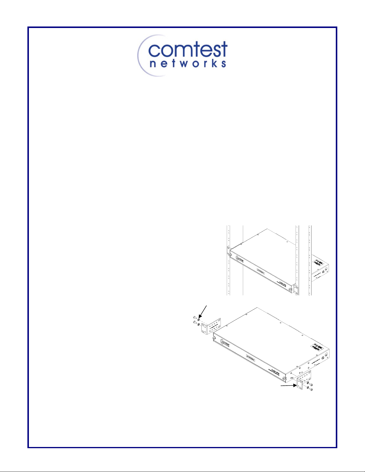
• 19 Inch Mounting
For 19 inch mounting, the long side of the
mounting bracket is attached to the side of the
shelf. There are three positions to mount the
bracket on the shelf and four positions on the
mounting bracket. The Rack Mounting Bracket can
also be mounted with the flange at the back. Thus,
there are 24 possible mounting positions for the
Rack Mounting Bracket. Choose a suitable
mounting position for the shelf then, using the
provided 10-32 screws and lock washers, attach
the bracket to each side of the shelf. Place the shelf in position on the rack and, using the appropriate
screws and lock washers, atta ch t he shelf to the rack. Please note the hardware (screws) required to
mount the shelf to the rack is not supplied with the 4048 shelf mounting kit.
Mounting Hardware
Mounting Bracket
Rev 2-5 June 2009 Page 1 of 6
A
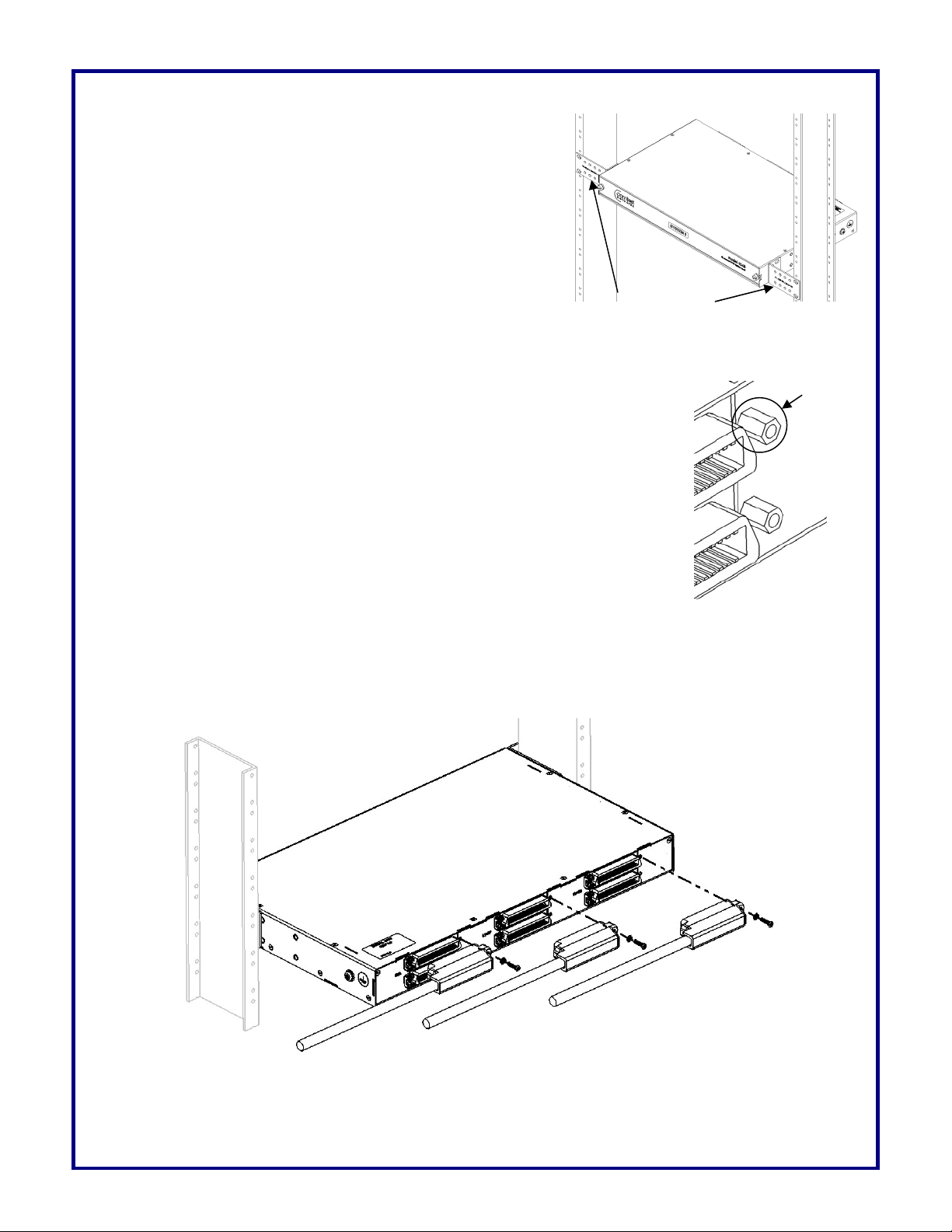
• 23 Inch Mounting
For 23 inch mounting, the short side of the mounting bracket
is attached to the side of the shelf. There are three positions
to mount the bracket on the shelf. Choose a suitable
mounting position for the shelf then, using the provided 10-32
screws and lock washers, att a ch the bracket to each side of
the shelf. Place the shelf in position on the rack and, using
the appropriate screws and lock washers, attach the shelf to
the rack. Please note the hardware (screws) required to
mount the shelf to the rack is not supplied with the 4048 shelf
mounting kit.
Mounting Brackets
Cabling Overview
New Installations
The 4048 Splitter Shelf cabling configurations will vary depending on installation
locations and the number of lines supported by the DSLAM. However, the physical
interface to the rear panel connectors is standard 50-pin RJ-21 type receptacle
connectors. Each splitter card uses 24 pairs of the 25 pairs available on each 50-pin
connector. After the shelf has been attached to the rack, the cabling can be prepared
as shown below.
The threaded mounting holes for the RJ-21 covers are designed to utilize ¾” captive
pan head screws. However, if only 0.425” captive pan head screws are available,
jack screws will have to be screwed into the RJ-21 connectors before assembling the
cover. Jack screws are available separately, order Comtest part number: HW-JS0203ZI.
dd if using
.425” screws
For improved DSL performance, Comtest recommends the use of CAT 5, or better, cabling on the DSL
connectors for our 4048 Splitter Shelf in order to ensure that optimum system performance is achieved and
maintained. Comtest suggest that the CAT 5 mating connectors used be equipped with either a 90
o
or 120o
cover so that routing of the cables is simplified.
POTS Cable
LOOP Cable
DSL Cable
CAUTION - To reduce the risk of fire, use only No. 26 AWG or larger telecommunication line cord/cable.
Rev 2-5 June 2009 Page 2 of 6
 Loading...