

Page 1
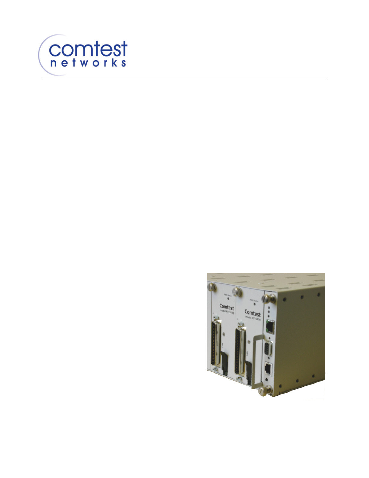
MTAS-192 METALLIC TEST ACCESS SYSTEM
Installation
Guide
Date: May 1, 2008
Version: 1.8 Release
Part No.: CT-IG-MTAS192
Page 2
CT-IG-MTAS192-2008-v1_8.doc
Revision History
ISSUE DATE REASON FOR CHANGES
1.0 Aug. 2005 Creation
1.1 Dec. 2005 Various Updates and formatting changes
1.2 Jan. 2006 Updated network configuration procedures and cabling
requirements
1.3 Jan. 2006 Added comments required for CSA / UL and a table
summarizing interface cables required / recommended
1.4 Feb. 2006 Updated MS Word source to contain Issue 1.3 PDF content
changes, added Appendix E, updated figures, and added
troubleshooting flowcharts to Chapter 5.
1.5 Apr. 2006 Added additional comments required for CSA / UL in Chapter 2
1.6 Jun. 2006 Added additional comments required for CSA / UL in Chapter 2
and Appendix B
1.7 Mar. 2008 Updated document with reference to new line cards MT-5820V
and MT-5821
1.8 May 2008 Added TAL pin-out wiring configuration for 4-wire applications
in Table 17.
Updated Contact Information in Appendix B.
List of Changes:
PAGE SECTION CHANGE DESCRIPTION
Warnings
Throughout this guide the reader will note various warnings. The purpose of these
warnings is to alert the reader to certain risks that may be encountered during the
installation of the Comtest MTAS-192 shelf in a Central Office environment. They are
categorized in terms of risk of injury to personnel and risk of damage to equipment.
The warnings are listed below from most to least threatening.
Danger: Danger indicates the presence of a hazard that will cause severe injury, death,
or substantial property damage if the hazard is not avoided.
ii
Page 3

CT-IG-MTAS192-2008-v1_8.doc
Warning: Warning indicates the presence of a hazard that can cause severe injury,
death, or substantial property damage if the hazard is not avoided.
Caution: Caution indicates the presence of a hazard that will or can cause minor injury
or property damage if the hazard is not avoided.
iii
Page 4

Page 5

CT-IG-MTAS192-2008-v1_8.doc
Table of Contents
Table of Contents..........................................................................................................v
Chapter 1 Introduction..............................................................................................1
1.1 Overview........................................................................................................1
1.2 The Metallic Test Access System.................................................................. 1
1.3 Hardware Overview ....................................................................................... 3
1.3.1 The MTAS Shelf............................................................................... 3
1.3.2 The Test Access Controller Cards....................................................8
1.3.3 The Line Cards (Splitter Cards and Test Access Only Cards)..........9
Chapter 2 Preparing for Installation ...................................................................... 13
2.1 Installation Personnel................................................................................... 13
2.2 Site Survey .................................................................................................. 13
2.3 Environmental..............................................................................................13
2.4 Tools and Materials Required...................................................................... 13
2.5 Ethernet Requirements................................................................................ 14
2.6 Shelf Power Supply ..................................................................................... 14
2.7 Physical Requirements................................................................................14
2.8 Unpacking....................................................................................................15
2.9 Inspection .................................................................................................... 15
2.10 Packing List ................................................................................................. 15
2.10.1 Shelf ............................................................................................... 15
2.10.2 Cards..............................................................................................16
Chapter 3 Installing the MTAS Shelf......................................................................17
3.1 Mounting the MTAS-192 Shelf.....................................................................17
3.2 Installing the MTAS Circuit Packs................................................................17
Chapter 4 Cabling.................................................................................................... 21
4.1 Backplane Connectors.................................................................................21
4.1.1 MTAS-CM Connectors ................................................................... 24
4.1.2 MTAS-CS Connectors.................................................................... 24
4.1.3 xDSL Filter Card Connectors..........................................................25
4.2 Cabling......................................................................................................... 25
4.2.1 Grounding Connector ..................................................................... 26
v
Page 6

CT-IG-MTAS192-2008-v1_8.doc
4.2.2 Power Feeds .................................................................................. 26
4.2.3 Connecting Line/Facility and POTS/Equipment RJ-21
Connectors..................................................................................... 28
4.2.4 Connecting to DSL ......................................................................... 29
4.2.5 Connecting to the Control Card......................................................30
4.2.6 Connecting the Test Head to the MTAS-192 Shelf......................... 30
4.2.7 Daisy-chaining Multiple MTAS-192 Shelves................................... 30
4.2.8 Connecting MAJOR and MINOR Alarm Ports ................................ 32
Chapter 5 Activation and Testing .......................................................................... 33
5.1 Introduction.................................................................................................. 33
5.2 Powering the MTAS-192.............................................................................. 33
5.3 Validating Operation of Control Cards and Line Cards................................ 33
5.4 Communicating with the MTAS.................................................................... 36
5.4.1 Via the Ethernet Port ...................................................................... 36
5.4.2 Via the Serial Port........................................................................... 36
5.5 IP Network Configuration............................................................................. 37
Appendix A Specifications......................................................................................... 41
Appendix B Repair and Return Services................................................................... 51
Appendix C Warranty.................................................................................................. 53
Appendix D Acronyms and Abbreviations................................................................ 55
Appendix E Recommended Cabling Practices......................................................... 57
Index 63
# # #
vi
Page 7
CT-IG-MTAS192-2008-v1_8.doc
Comtest Networks
MTAS-192
Chapter 1
Introduction
1.1 Overview
This chapter provides an introduction to the 192-port Comtest Networks Metallic Test
Access System (MTAS-192).
1.2 The Metallic Test Access System
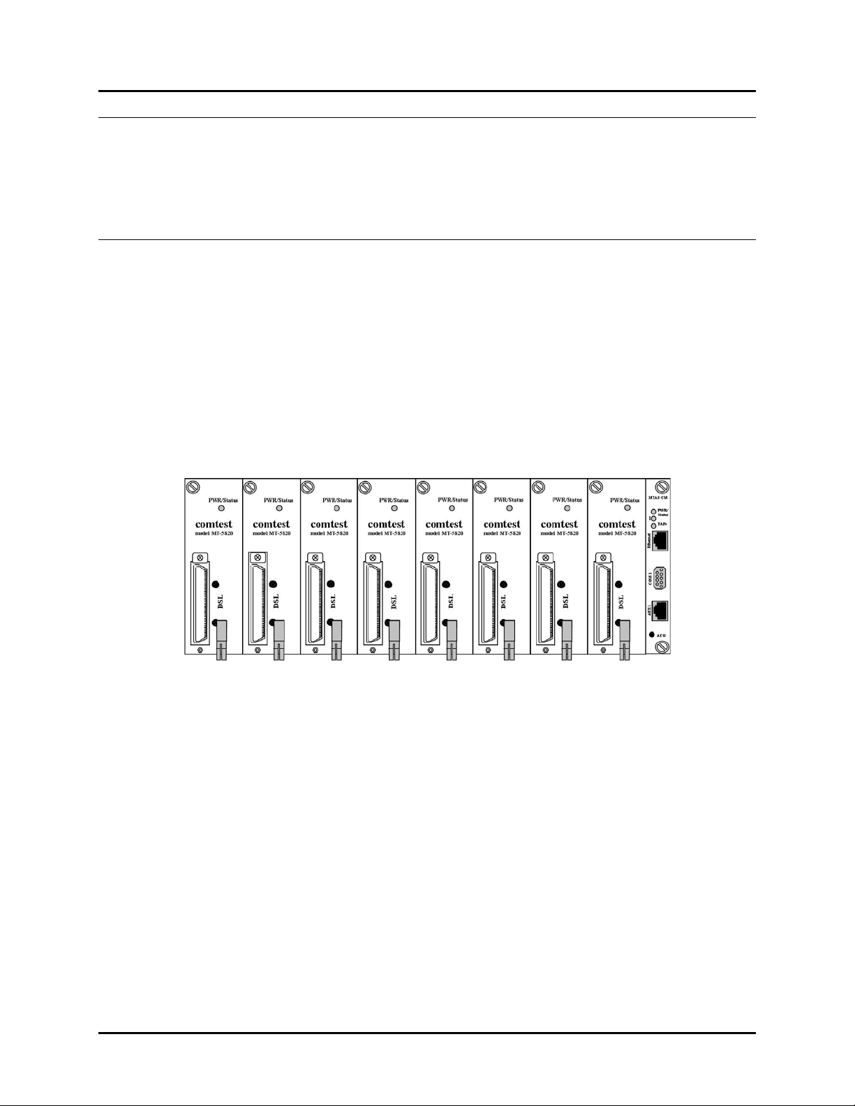
The MTAS-192 is a high density, modular metallic test access system (MTAS) for DSL
splitter and non-splitter applications. It combines xDSL Splitter, Metallic Test Access
Unit (MTAU), and Splitter/MTAU functionality into a single physical shelf/chassis, the
MTAS-192.
2
Figure 1: MTAS-192 (Front Panel)
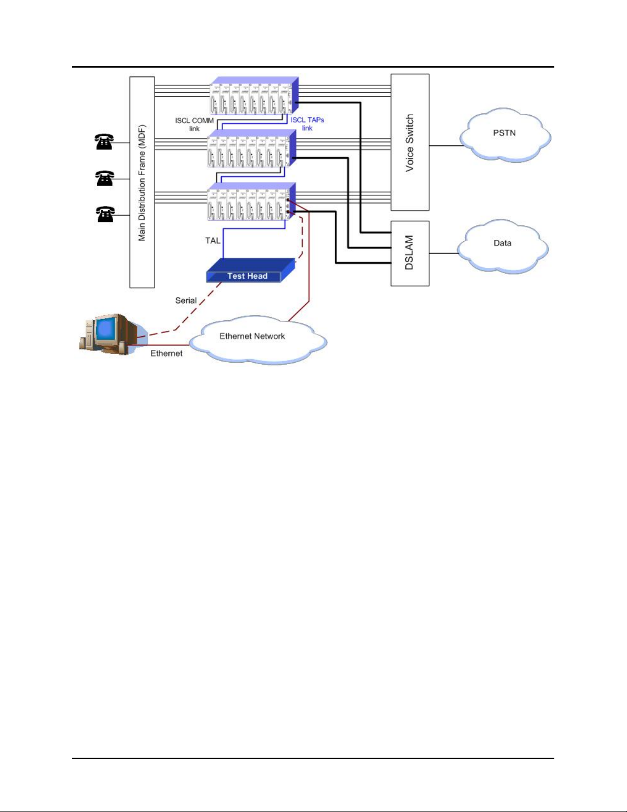
The MTAS-192 sits between the subscriber lines and the DSLAM (Digital Subscriber
Loop Access Multiplexer), enabling simultaneous voice and data services over the
subscriber’s local loop, in conjunction with remote test access capability for customer
line monitoring and troubleshooting. The MTAS enables the user to non-intrusively
monitor the line or perform intrusive test access upstream and downstream. Test
access functionality can be controlled by any leading broadband test head or
Support System (
The MTAS offers up to 192 two-wire circuits per 3 rack units (RU) of test access and
can be daisy-chained to provide over 2,000 ports per configuration. The MTAS product
family consists of the test access shelf, control modules, and choice of cards for DSL
splitter and non-splitter test access applications. The backplane houses the POTS and
LINE interfaces using standard 50 pin (25 pair) female RJ-21 connectors. The DSL
interface is located on the front of each line card, also using a standard 50 pin (25 pair)
female RJ-21 connector.
OSS) that is compliant with the GR-834 and GR-818 standards.
Operational
June 2006 Installation Guide
1
Page 8
Comtest Networks
MTAS-192
CT-IG-MTAS192-2008-v1_8.doc
Figure 2: MTAS-192 in the Network
The MTAS-192 provides two (2) four-wire Test Access Paths (TAPs), with monitor,
bridged, look-in, and look-out functionality. The four-wire TAP provides separate look-in
and look-out pairs with access controlled by Transaction Language 1 (TL1) messages
sent over an Ethernet or an RS-232 serial port directly to each MTAS-192 System.
2
Installation Guide June 2006
Page 9
CT-IG-MTAS192-2008-v1_8.doc
Comtest Networks
MTAS-192
1.3 Hardware Overview
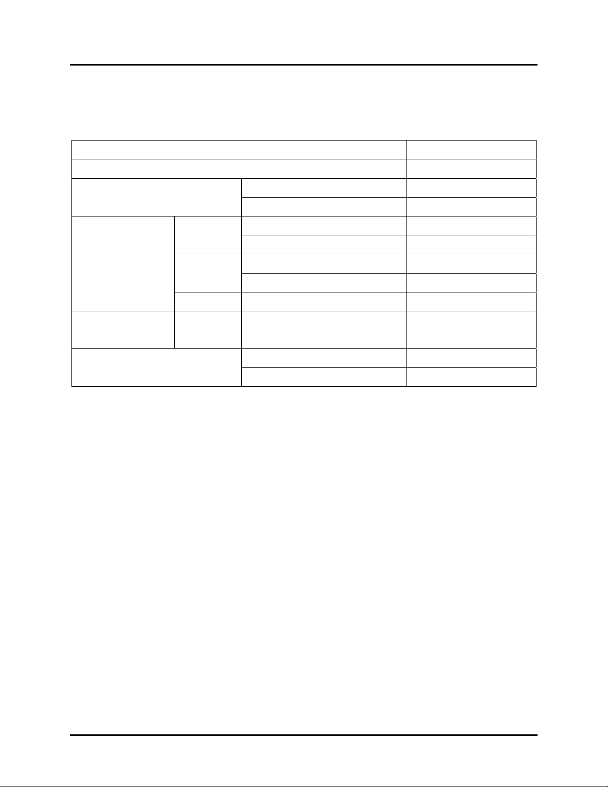
The MTAS-192 Metallic Test Access System has the following parts.
Table 1: Components of the MTAS-192 Metallic Test Access System
Component Model Number
High Density, Test Access Shelf MTAS-192
Test Access Controller Card
Master MTAS-CM
Slave MTAS-CS
North
American
Standard NA-5820
With Test Access MT-5820
Splitter Card
Standard EU-5807
(ADSL2+)
ETSI
with Test Access MT-5807
ISDN With Test Access MT-5821
Splitter Card
(VDSL2)
North
American
With Test Access MT-5820V
for 2-wire Lines MT-501
Test Access Only Card
for 2- and/or 4-wire Lines MT-502
1.3.1 The MTAS Shelf
The MTAS-192 shelf is 3 Rack Units in height and can be rack-mounted in either a 19”
or 23” ANSI- and ETSI-dimensioned equipment rack or cabinet using universal
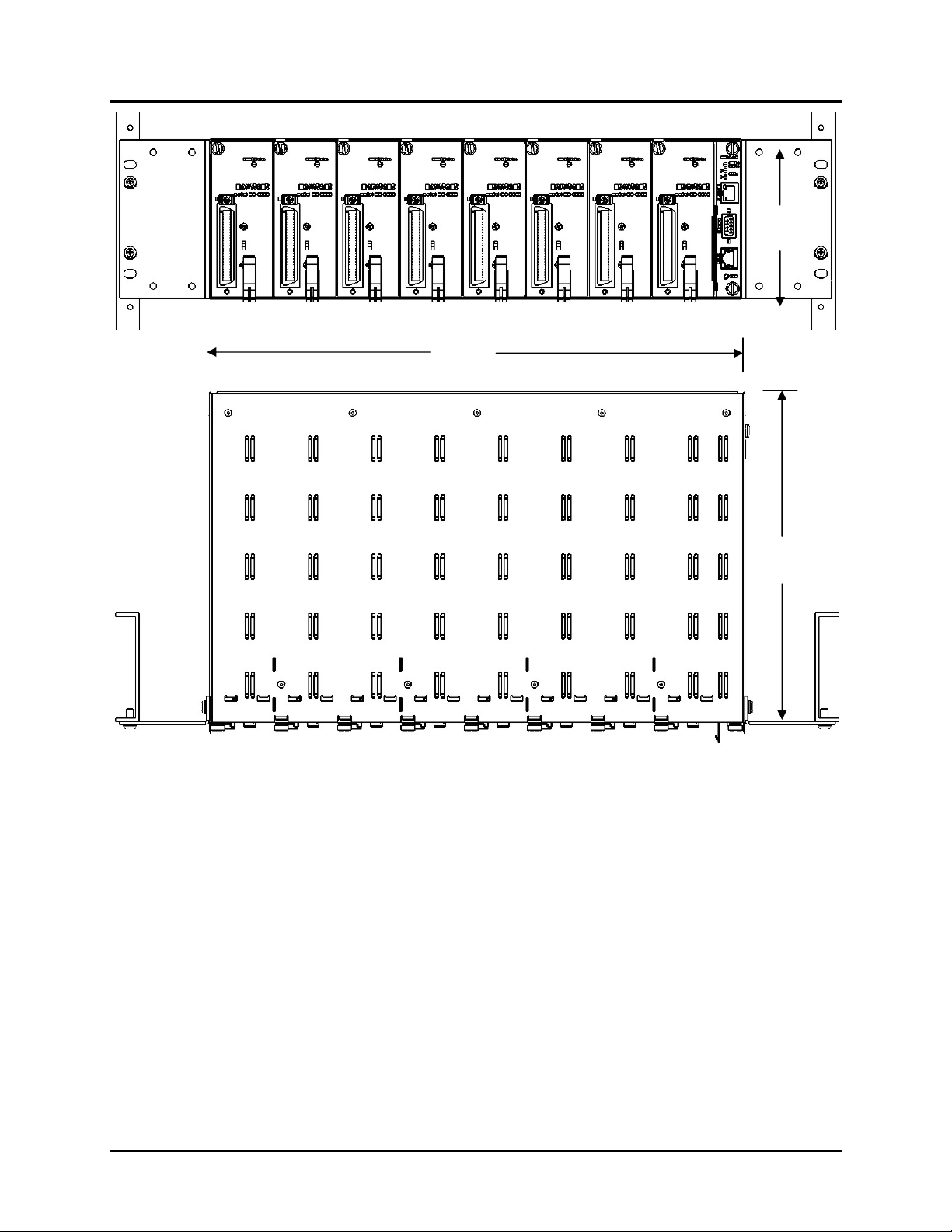
mounting flanges. The actual dimensions of the shelf are 5.22″ high by 17.3″ wide
(without the mounting flanges) by 10.5″ deep. Refer to Figure 3.
MTAS-192 shelf contains nine card slots. The first eight slots (#1-8, labeled from left to
right) are reserved for line cards, each providing xDSL splitter and/or metallic test
access to 24 2-wire lines. Therefore, one MTAS-192 provides MTA to 192 2-wire lines.
The ninth slot is reserved for the Control Card.
June 2006 Installation Guide
3
Page 10
Comtest Networks
MTAS-192
CT-IG-MTAS192-2008-v1_8.doc
5.22"
17.3"
10.5"
Figure 3: Front and Top Views of MTAS Shelf Showing Flanges for 23" Rack
The MTAS-192 shelf has eight line card slots (slots #1-8) for up to eight line cards in
any combination of:
• MT-5820(V) North American Splitter with Test Access or
MT-5807 ETSI Splitter with Test Access or
MT-5821 ISDN Splitter with Test Access
• NA-5820 North American Splitter Cards or
EU-5807 ETSI Splitter Cards
• MT-501/MT-502 Test Access only cards
and one slot (slot #9) for either:
• MTAS-CM control card (master) or
• MTAS-CS control card (slave).
4
Installation Guide June 2006
Page 11
CT-IG-MTAS192-2008-v1_8.doc
Comtest Networks
MTAS-192
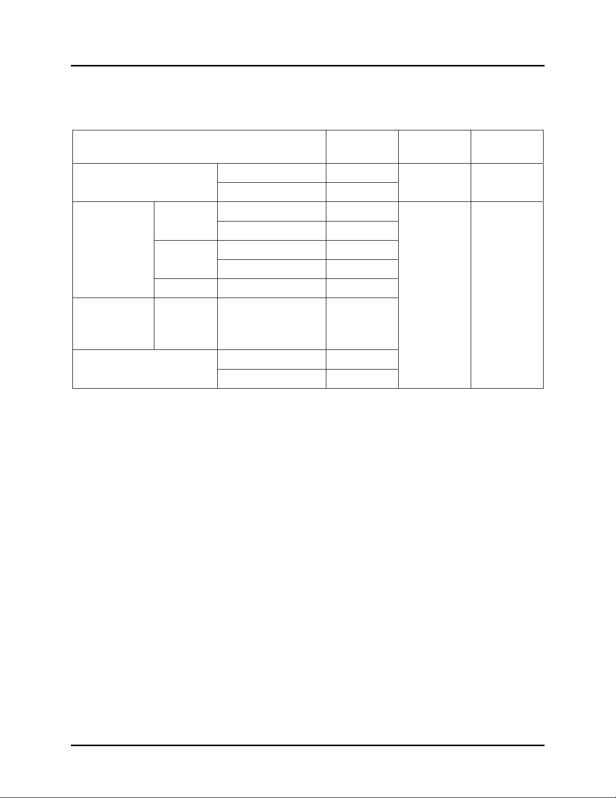
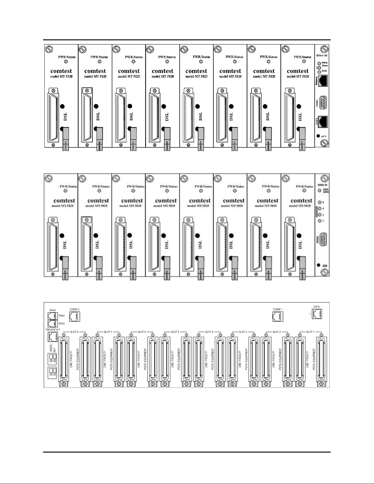
This is summarized in Table 2 below. A sample MTAS-192 system containing eight
MT-5820 line cards is shown in Figure 4 and Figure 5.
Table 2: Card Slot Assignments for the MTAS-192
Component
Test Access Controller
Card
North
Splitter
American
Cards
(ADSL2+)
ETSI
ISDN With Test Access MT-5821
Splitter
Cards
North
American
Model
Number
Master MTAS-CM
Slave MTAS-CS
Type
Controller
Cards
Standard NA-5820
With Test Access MT-5820
Standard EU-5807
with Test Access MT-5807
Line
Cards
With Test Access MT-5820V
Use in
Slot(s)…
9
1-8
(VDSL2)
2-wire MT-501
Test Access Only Card
2- and/or 4-wire MT-502
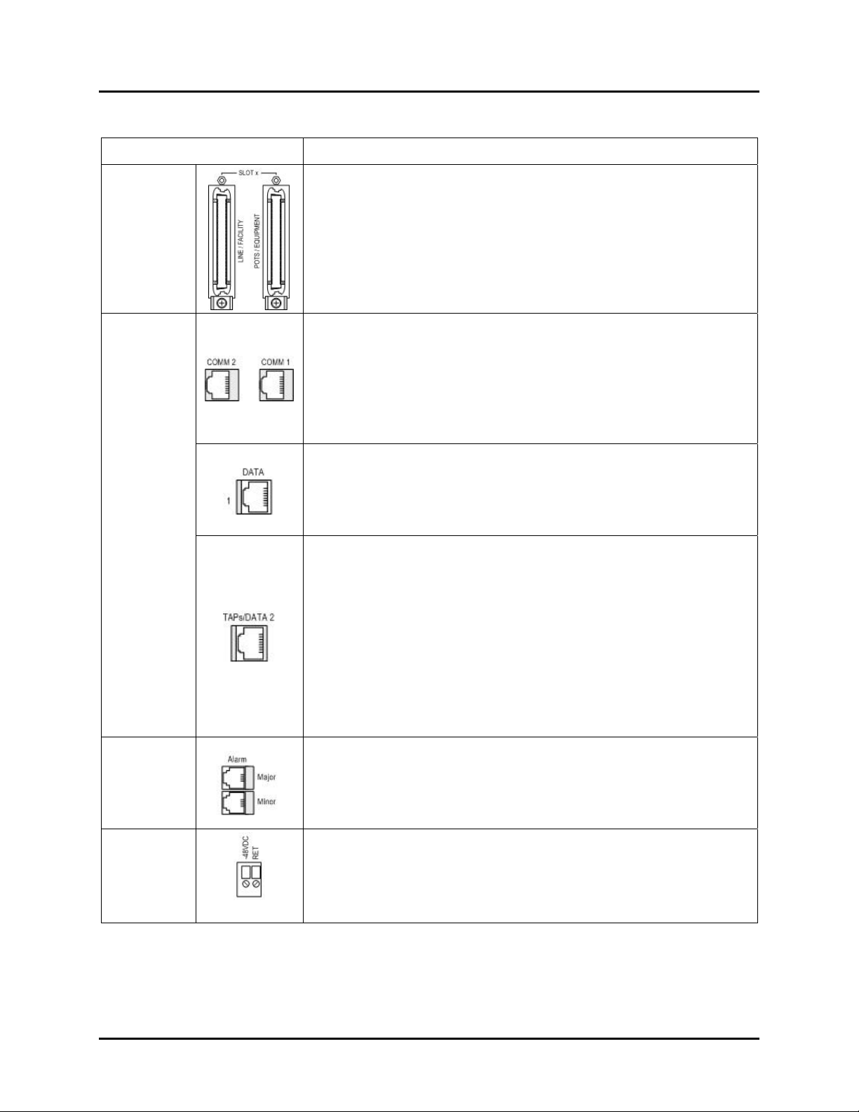
Table 3 lists visible features and interfaces on the rear panel of the MTAS-192 shelf.
The complete rear panel is shown in Figure 6.
June 2006 Installation Guide
5
Page 12
Comtest Networks
MTAS-192
Figure 4: MTAS-192 Front View with Master Control Card (MTAS-CM)
CT-IG-MTAS192-2008-v1_8.doc
2
Figure 5: MTAS-192 Front View with Slave Control Card (MTAS-CS)
Figure 6: MTAS-192 Rear View
Refer to Chapter 4: Cabling and Appendix A for connector pin-outs. Refer to Chapter 5:
Activation and Testing for LED information.
6
Installation Guide June 2006
Page 13
CT-IG-MTAS192-2008-v1_8.doc
Table 3: Rear Panel Connectors of the MTAS-192 Shelf
Connector/Function Description
24 Line/Facility and 24 POTS/Equipment Pairs
RJ-21
(8 sets)
50-pin (25 pair) RJ-21 female connector – 1/ line card slot.
Pairings correspond to eight (8) splitter/TAU line card slots
#1-8 in the shelf.
COMM 1 and COMM 2 for ISCL Bus
RJ-45 shielded female jacks for COMM 1 communications
ports on top right and COMM 2 communications ports on
top left. Used for daisy chaining the ISCL bus from the
chassis (COMM 1 is ISCL bus OUT, COMM 2 is ISCL bus
IN).
DATA 1 for TAL Bus
Comtest Networks
MTAS-192
RJ-45
RJ-11
Dual Wire
Terminal
Header
RJ-45 shielded female jack for DATA 1 TAL extensions
port. Used to extend the TAL bus to the next shelf in a
daisy-chained network.
TAPs / DATA 2 port
RJ-45 shielded female jack. Test Access Link (TAL)
consisting of two 4-wire Test Access Paths (TAPs). Each
TAP delivers simultaneous metallic test access to both the
DSLAM and Line side of a port under test.
For a Stand-alone or master shelf configuration, this port is
used for connection to the test head.
For the slave shelf configuration, this port is the TAL input
connector for a daisy chain.
Major and Minor External Alarm Contacts
RJ-11 female jack. Shelf Major and Minor Alarm outputs.
Normally open, dry contacts for visual and audible alarms.
Located on the top left of the chassis.
Shelf Power
Two sets of -48VDC Battery and Return terminals (for both
A and B power feeds), located on the left side.
June 2006 Installation Guide
7
Page 14
Comtest Networks
CT-IG-MTAS192-2008-v1_8.doc
MTAS-192
1.3.2 The Test Access Controller Cards
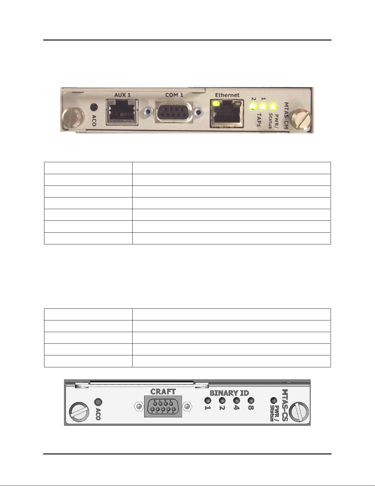
The MTAS-CM (Control Master) card has the following visible features and interfaces
on its front panel.
Figure 7: Test Access Controller Card MTAS-CM (Control Master) (Rotated 90 Degrees)
Table 4: Features of the MTAS-CM Control Master Card
Item Description
PWR / Status LED One Tri-colour LED to show PWR and Status
TAPs LEDs Two TAPs LEDs to show status of TAPS 1 and 2
Ethernet Female RJ-45 shielded jack for 10/100 BaseT cable
COM 1 Female RS-232 shielded DB-9 connector (debug port)
AUX 1 Female RS-232D shielded RJ-45 connector
ACO (Alarm Cut-off) Push button cutoff switch for audible alarms
More than one MTAS-192 shelf can be daisy-chained into a master/slave configuration.
In such applications, a slave version of the Test Access Controller Card is available
(MTAS-CS). The MTAS-CS (Control Slave) card has the following visible features and
interfaces on its front panel.
Table 5: Features of the MTAS-CS Control Slave Card
Item Description
PWR / Status LED One Tri-colour LED to show PWR and Status
Binary ID LEDs Four LEDs to identify the Shelf ID (1-11)
CRAFT Female RS-232 shielded DB-9 connector (debug port)
ACO (Alarm Cut-off) Push button cutoff switch for audible alarms
Figure 8: Test Access Controller Card MTAS-CS (Control Slave) (Rotated 90 Degrees)
8
Installation Guide June 2006
Page 15
CT-IG-MTAS192-2008-v1_8.doc
Comtest Networks
MTAS-192
1.3.3 The Line Cards (Splitter Cards and Test Access Only Cards)
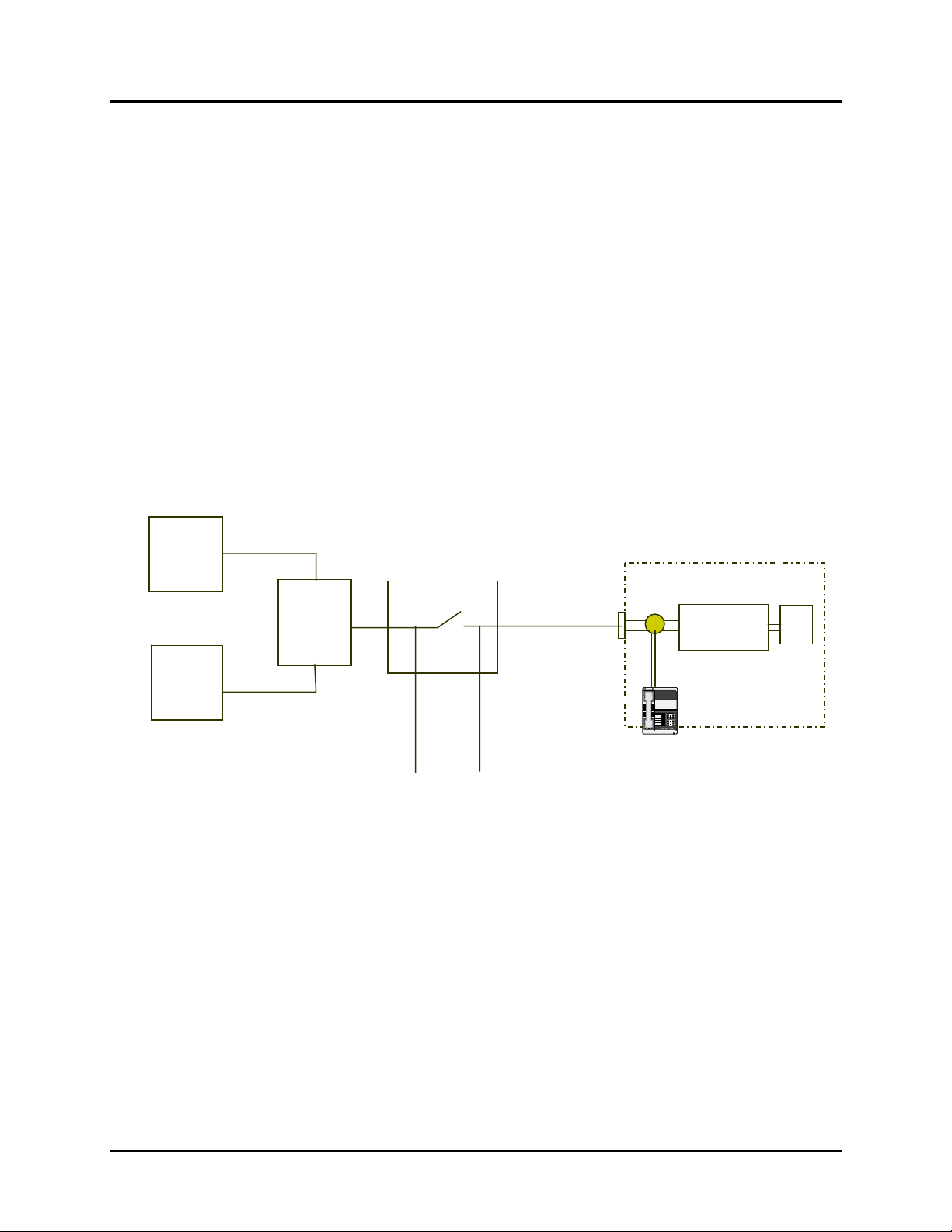
There are 6 unique types of line cards divided into 2 categories: Splitter Cards (4
varieties) and Test Access Only Cards (2 varieties) (refer to Table 2).
Each splitter card has a DSL (Digital Subscriber Loop) interface using a standard 50-pin
(25 pair) RJ-21 female connector. In addition, each splitter card has two TAPs (Test
Access Paths) and each TAP consists of 2 pairs of wires (making a 4-wire TAP):
• One for the upstream (Equipment) side called AE
• One for downstream (Facility) side called AF.
The AF (facility) pair is intended for testing on the line (facility) side and it is always used
in any test mode. The AE (equipment) pair is intended for testing on the equipment side.
Equipment Side (E)
(Upstream)
DSLAM
PSTN
Class 5
Splitter
MTAU (MTAS -192)
AE
AF
RTU (Test Head)
Figure 9: Test Access Paths (TAPs)
Facility Side (F)
(Downstream)
CPE
Splitter
DSL
Modem
123
456
789
8#
*
PC
June 2006 Installation Guide
9
Page 16
Comtest Networks
p
p
g
g
A
CT-IG-MTAS192-2008-v1_8.doc
MTAS-192
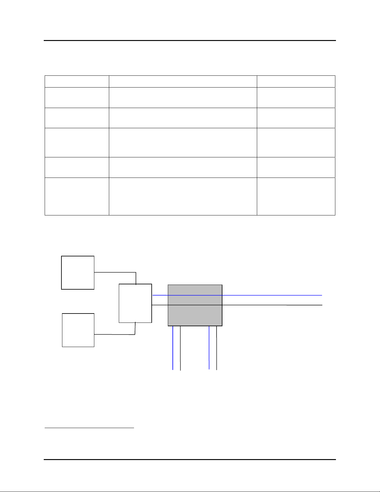
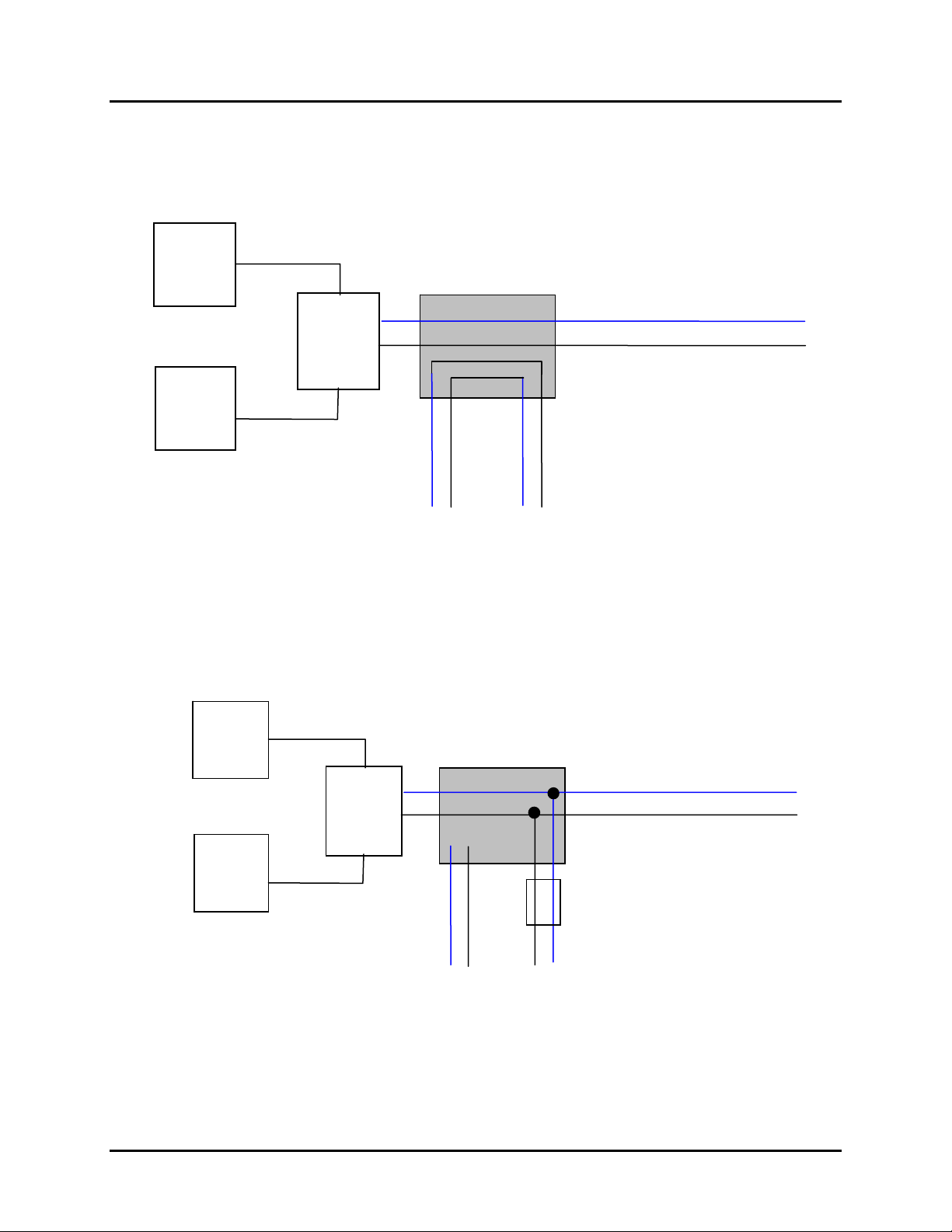
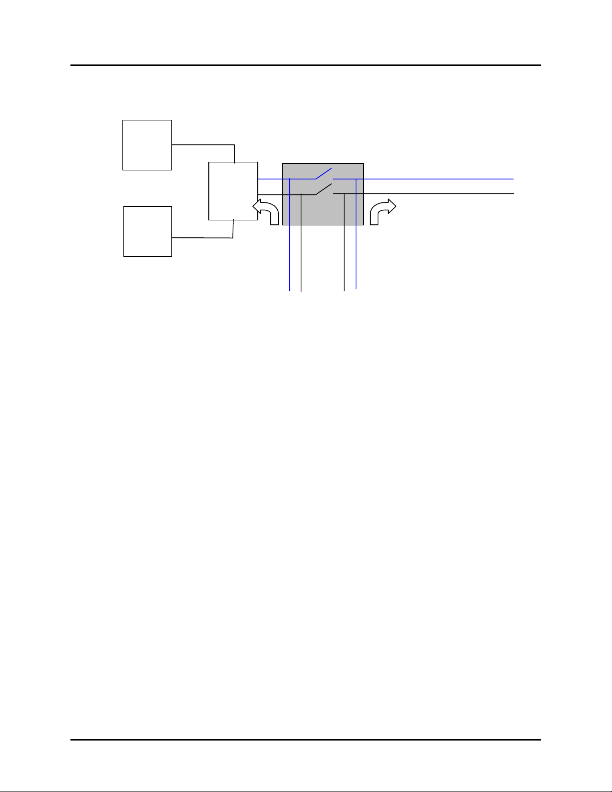
Each splitter card has five (5) modes, which are explained below.
Table 6: Splitter Card Modes
Mode Description TL1 Command
1
Transparent/
Isolated
Loop-around
High-impedance
Monitor
Bridged Monitor
Split
Equipment Side (E)
(Upstream)
DSLAM
In this mode, all test connections are
released. This is the default mode.
In this mode, the AF and AE sides of a
TAP are looped back at the line card.
This mode uses the AF portion of the TAP
bus and performs a hitless connection to
provide access for monitoring.
This mode connects the AF pair directly to
the circuit under test.
Split Mode access breaks the cable pair to
be tested in two directions, one provided
by AF (towards the customer) and AE
(towards the equipment).
Facility Side (F)
(Downstream)
MTAU (MTAS-192)
ccess Point
DISC-TACC
CONN-LPACC-MET
CONN-TACC-MET
CONN-MON
CHG-SPLIT
2–Wire Circuit
Splitter
Ti
Rin
Ti
Rin
PSTN
Class 5
TT
AE
RR
AF
RTU (Test Head)
Figure 10: Transparent/Isolation Mode
1
TL1 commands are explained in the MTAS-192 User Guide.
10
Installation Guide June 2006
Page 17
CT-IG-MTAS192-2008-v1_8.doc
A
pTip
g
g
A
Comtest Networks
MTAS-192
Equipment Side (E)
(Upstream)
DSLAM
PSTN
Class 5
Splitter
MTAU (MTAS-192)
ccess Point
Ti
Rin
TT
AE
Rin
RR
AF
RTU (Test Head)
Figure 11: Loop-Around Mode
Facility Side (F)
(Downstream)
2–Wire Circuit
Equipment Side (E)
(Upstream)
DSLAM
Splitter
MTAU (MTAS-192)
ccess Point
Tip
Ring
Facility Side (F)
(Downstream)
Tip
Ring
2–Wire Circuit
PSTN
Class 5
TT
AE
High (Z) Impedance
RR
AF
RTU (Test Head)
Figure 12: High-Impedance Monitor Mode for the Splitter/Access Two-Wire TAP
June 2006 Installation Guide
11
Page 18
Comtest Networks
MTAS-192
CT-IG-MTAS192-2008-v1_8.doc
Equipment Side (E)
(Upstream)
DSLAM
PSTN
Figure 13: Split Mode for Testing in Both Directions
Splitter
MTAU (MTAS-192)
4-Wire Access
Tip
Ring
TT
AE
RR
AF
RTU (Test Head)
Facility Side (F)
(Downstream)
Tip
Ring
2–Wire Circuit
Refer to the MTAS User Guide for shelf and TL1 command specifications.
# # #
12
Installation Guide June 2006
Page 19

CT-IG-MTAS192-2008-v1_8.doc
Comtest Networks
MTAS-192
Chapter 2
Preparing for Installation
2.1 Installation Personnel
Comtest recommends that all installation activities be conducted by certified central
office (CO) installers.
2.2 Site Survey
Comtest recommends that a site survey be conducted in advance by experienced
personnel to determine and assign the following:
• equipment rack location(s)
• shelf position(s) in the rack
• power distribution panel and fusing
• suitable disconnect device for power feed
• connections to OSS and test head.
2.3 Environmental
The MTAS-192 is designed to be installed in a restricted-access location such as a
Central Office environment or remote hardened enclosures. The MTAS-192 is suitable
for mounting on concrete or other non-combustible surface only. The temperature range
for the MTAS-192 is -40 to +60
2.4 Tools and Materials Required
The MTAS-192 is easy to install. The following equipment is required:
• One (1) large Philips-head (star) screwdriver
• One (1) narrow, long blade slot-edge screwdriver
• Tie wraps for forming and securing various cables to equipment and cable racks
• Bolts for securing the MTAS to the equipment rack
2
degrees Celsius.
• 8-wire CAT5 cable (shielded is recommended) for TAL connections
• 8-wire CAT5 cable (shielded is recommended) for Ethernet and serial
connections
2
To operate in temperatures above this range please contact Comtest Networks
June 2006 Installation Guide
13
Page 20
Comtest Networks
CT-IG-MTAS192-2008-v1_8.doc
MTAS-192
• RJ-45 plugs (shielded or non-shielded, depending upon CAT5 cable us ed), up to
6 per chassis
• If daisy-chaining MTAS shelves, 8-wire CAT5 shielded cable for COMM
connections is required.
NOTE: For daisy-chain configurations, CAT5 shielded cable is required for COMM
connections and it must be properly grounded on both ends. Refer to Chapter 4 and
Appendix A for more details.
2.5 Ethernet Requirements
The MTAS requires assignment and configuration of a static IP address, subnetwork
mask, and gateway. This information must be obtained prior to the MTAS Activation and
Testing phase of the installation.
NOTE: To be visible to the configuring PC, the PC and master MTAS shelves must
share the same IP subnetwork.
2.6 Shelf Power Supply
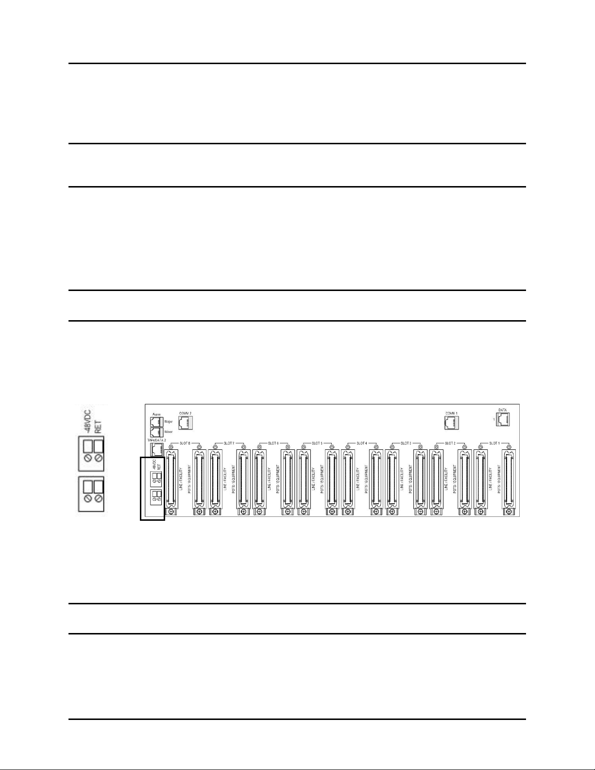
The MTAS-192 shelf is powered by standard –48VDC Central Office (CO) battery.
Although the shelf can operate from a single power feed, dual connectors are provided
for A and B power feed redundancy.
Figure 14: Dual Connectors for Power Feed
The power supply breakers/fuses required are minimum 1/2 A to maximum 1A; these
are typically located in the Power Distribution Bay/Block/Center at the top of the
equipment rack.
NOTE: The MTAS-192 power feeds must be connected to an appropriate disconnect
device
2.7 Physical Requirements
The MTAS-192 shelf is adaptable to 19" and 23" racks using universal mounting
flanges.
14
Installation Guide June 2006
Page 21

CT-IG-MTAS192-2008-v1_8.doc
Comtest Networks
MTAS-192
Each MTAS shelf requires three (3) Rack Units or 5.25 inches of vertical rack space.
The MTAS shelves may be installed directly above or below one another: there is no
vertical spacing required for cooling or cabling.
2.8 Unpacking
The MTAS is shipped in two separate boxes – one contains the MTAS-192 shelf, and
the other contains the circuit packs for the shelf. There are no special handling
requirements for the shelf; however, the circuit packs require standard ESD handling
precautions.
CAUTION: A grounded wrist strap should be worn at all times when handling the circuit
packs. Place cards in or on static bags when working with the cards.
NOTE: After unpacking, do not install the circuit packs into the shelf before the shelf is
mounted in the equipment rack. Mount the MTAS-192 shelf in the rack before inserting
circuit packs.
2.9 Inspection
Step 1. Using standard ESD handling precautions unwrap circuit cards one at a time.
Step 2. Consult the packing list (see section 2.10 Packing List) to verify that all items
have been received as ordered and inspect them for obvious physical damage.
Step 3. If there is damage, re-pack the item in the shipping materials in which it came
in and return to Comtest Networks using the standard defect return procedure
in Appendix B: Repair and Return Services.
Step 4. If there is no damage, go to Chapter 3: Installing the MTAS Shelf.
2.10 Packing List
Please verify the contents of your MTAS-192 shipment against the packing list(s).
2.10.1 Shelf
• One (1) MTAS-192 High Density, Test Access Shelf
• Two (2) universal ANSI ear mounts (flanges) for either 19 or 23" shelves, each
supplied with two (2) screws and two (2) washers
• One (1) ISCL bus terminator (RJ-45 connector 'dongle')
• One (1) Steward EMI (Electro-magnetic Interference) suppressor
• Optional Redundant Power Feed Steward EMI suppressor
• Optional RJ-21 Hex Nut kits
• Optional RJ-21 Angle Shroud kits.
NOTE: Hex Nut and Angle Shroud kits are based on the RJ-21 shroud type (D-type or
Angled) and screw length (0.75" or less than (<) 0.75") used to build the CAT5 RJ-21
24-pair cables that connect to the MTAS backplane POTS, Line, and line card DSL
June 2006 Installation Guide
15
Page 22

Comtest Networks
MTAS-192
RJ-21 female connectors. The kits consist of:
• Hex Nut kit: 8 hex nuts
• Angled Shroud kit: 8 tie wraps, 8 cable tie mounts.
2.10.2 Cards
• One (1) MTAS-CM Test Access Controller card Master or MTAS-CS Test Access
controller card Slave
• Up to eight line cards in any combination of:
o NA-5820 North American Splitter Card(s) or EU-5807 ETSI Splitter Card(s)
OR
o MT-5820(V) North American Splitter(s) with Test Access or MT-5807 ETSI
Splitters with Test Access or MT-5821 ISDN Splitters with Test Access OR
o MT-501 Test Access only card or MT-502 Test Access only card.
NOTE: There is no dongle/ terminator required for the Test Access Link extender bus.
CT-IG-MTAS192-2008-v1_8.doc
# # #
16
Installation Guide June 2006
Page 23
CT-IG-MTAS192-2008-v1_8.doc
Comtest Networks
MTAS-192
Chapter 3
Installing the MTAS Shelf
3.1 Mounting the MTAS-192 Shelf
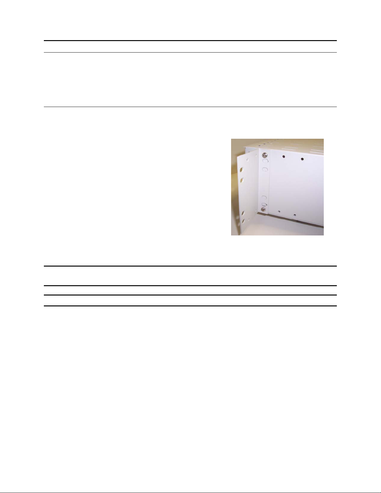
Step 1. The MTAS-192 shelf comes with two (2)
universal mounting flanges and four (4)
10-32 screws and washers. Attach the
left and right side universal mounting
flanges to the MTAS-192 shelf using the
supplied screws to set the depth of the
shelf with respect to the equipment rack.
For 19" racks, screw the long side of the
mounting flange to the shelf using the
supplied 10-32 screws and lock washers.
For 23" racks, screw the short side of the
mounting flange to the shelf.
Figure 15: Universal Mounting Flanges
Screwed to MTAS Shelf
WARNING: Using non-standard screws may pierce line cards in the shelf/chassis. Use
only bolts shipped with the MTAS-192 mounting flanges.
NOTE: Do not over-torque the screws.
Step 2. Once the mounting flanges are attached, screw the MTAS-192 shelf to the
equipment rack at the correct, pre-determined height using four 10-32 screws
(not supplied).
3.2 Installing the MTAS Circuit Packs
Step 1. Unpack the MTAS cards, observing all ESD precautions. Wear a grounding
wrist strap and/or use an anti-static mat.
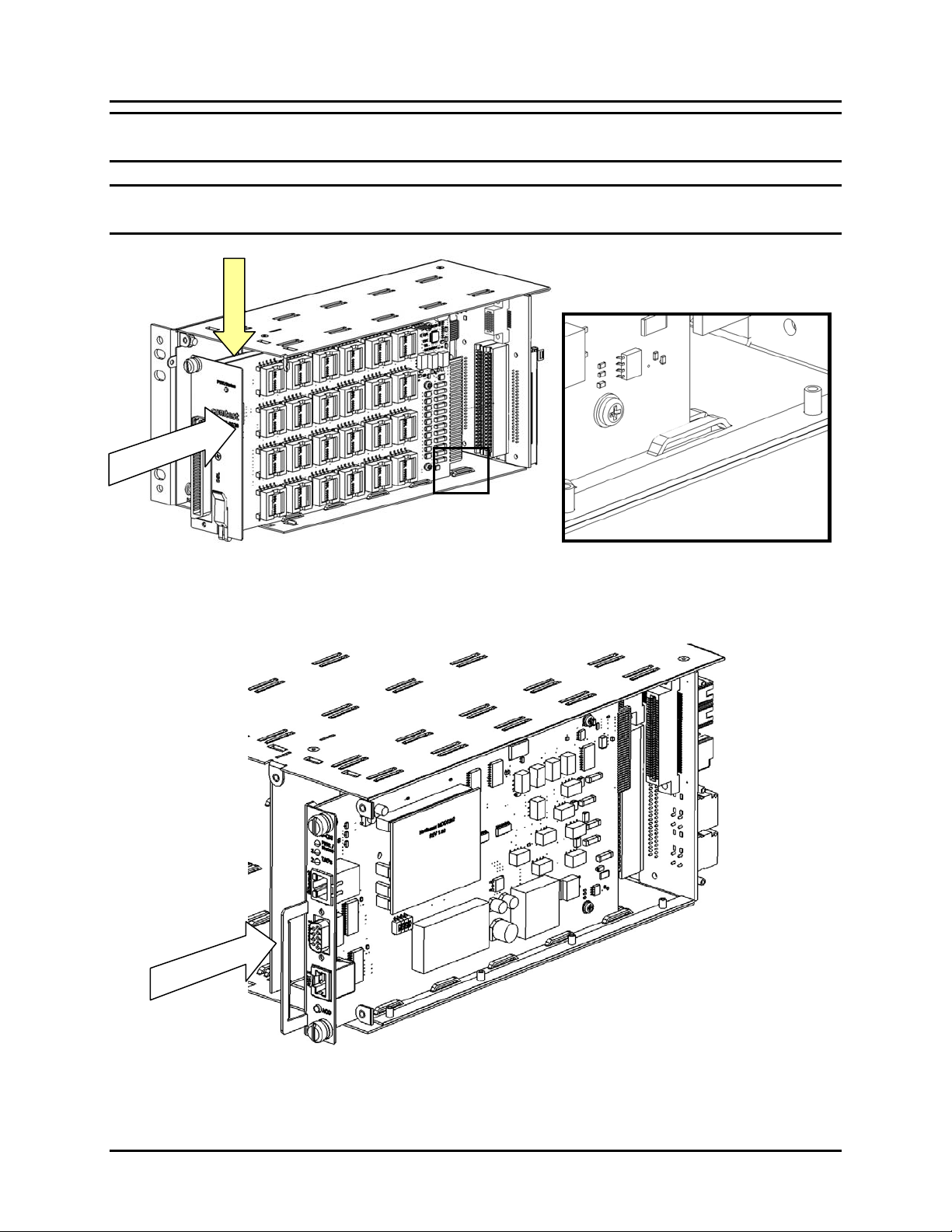
Step 2. Grasp the faceplate of the card with both hands, one hand at the top of the
faceplate, and one hand on the bottom.
Step 3. Pull the black card ejector/latch all the way back and insert the card into the
shelf using the guides at the top and bottom of the shelf to seat the card (see
Figure 16: Inserting a LINE Card).
June 2006 Installation Guide
17
Page 24
Comtest Networks
CT-IG-MTAS192-2008-v1_8.doc
MTAS-192
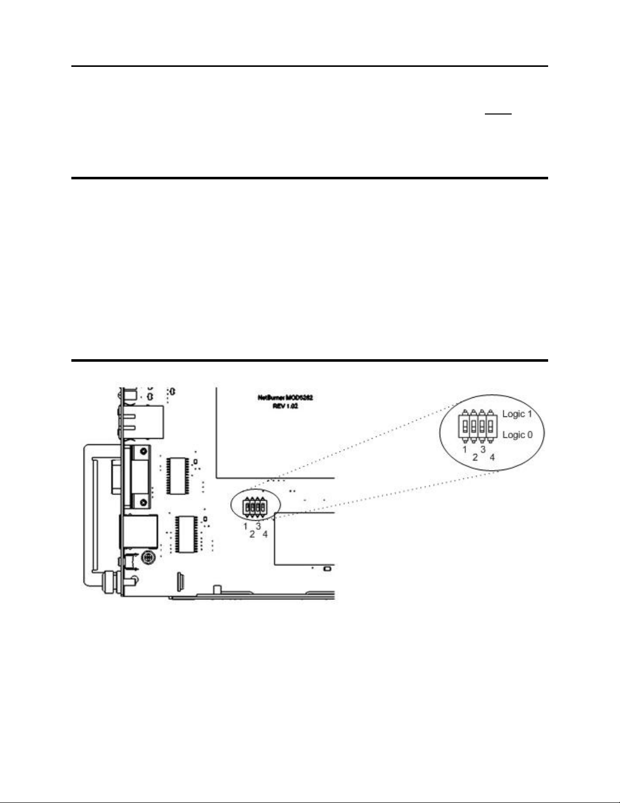
NOTE: On cards with two circuit boards, align the right-most circuit board with the card
guides (see Figure 16: Inserting a LINE Card Showing Magnified View of Card Guide).
CAUTION: While sliding in cards, ensure that the components on the circuit boards do
not catch on the shelf card tabs.
Figure 16: Inserting a LINE Card Showing Magnified View of Card Guide
Figure 17: Inserting a CONTROL Card Aligned with Card Guides
18
Installation Guide June 2006
Page 25
CT-IG-MTAS192-2008-v1_8.doc
Comtest Networks
MTAS-192
Step 4. When the card will go no further, pull the card ejector tab upwards and push it
towards the shelf in one motion to completely seat the card.
Step 5. When the card is completely seated, lock it in place by pushing and hand-
tightening the slotted card locking screws until they are tight – DO NOT OVER-
TORQUE.
Step 6. Repeat for all the cards to be installed on the shelf.
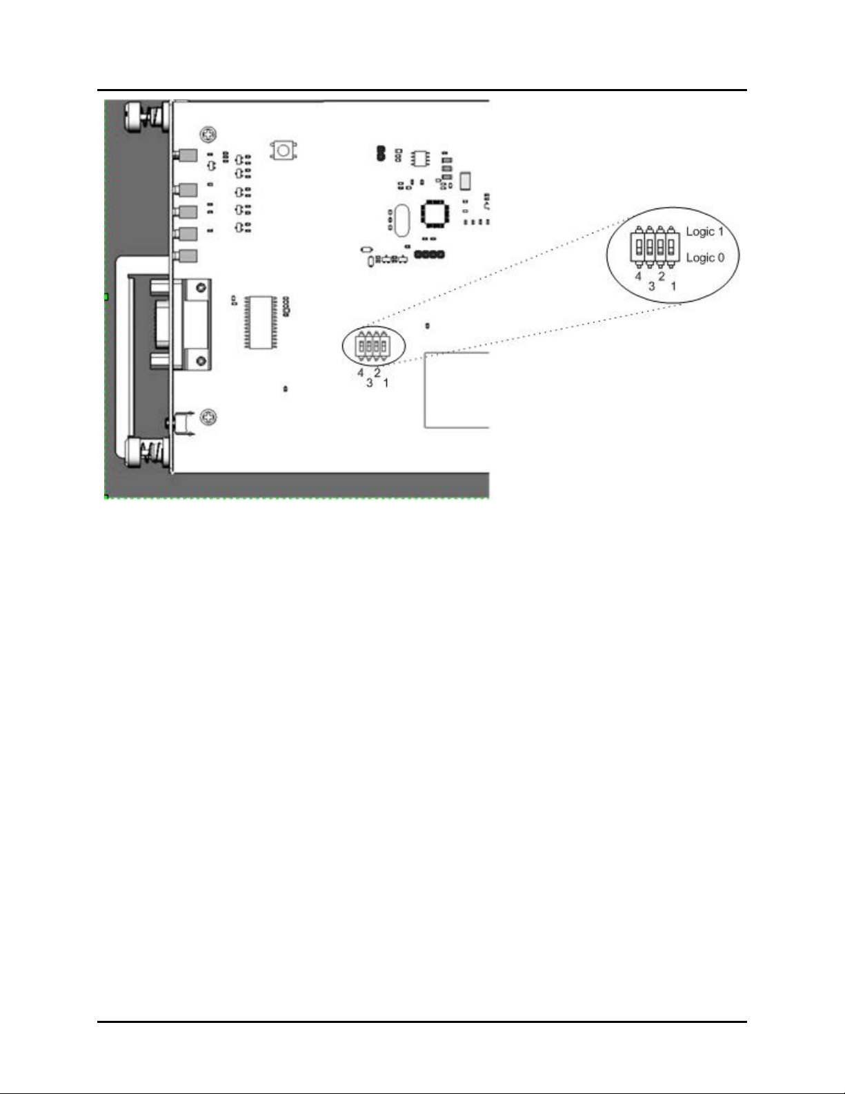
NOTE: The MTAS-CM (Master) control card has a block of DIP switches that are set to
a default setting of 0 (0-0-0-0) and factory-sealed with a plastic film. These DIP switches
must remain at 0-0-0-0 (see Figure 18: ). MTAS-CS (Slave) control card DIP switch
settings, however, must be set to identify the shelf's unique address in a daisy-chain of
up to 12 MTAS shelves
Slave shelves require their MTAS-CS cards to be set to a unique number between 1
and 11 in binary, to identify the slave shelf's logical ID in the daisy-chain. See Figure 18:
to locate DIP switches and consult Appendix A for the MTAS Control Card DIP switch
settings table.
In addition to physically inspecting the DIP switch settings, they can also be verified by
viewing the Binary ID LEDs (8, 4, 2, 1) on the slave card faceplate (see Figure 22).
Figure 18: MTAS-CM (Control Master) DIP Switch Location
June 2006 Installation Guide
19
Page 26
Comtest Networks
MTAS-192
CT-IG-MTAS192-2008-v1_8.doc
Figure 19: MTAS-CS (Control Slave) DIP Switch Location
# # #
20
Installation Guide June 2006
Page 27
CT-IG-MTAS192-2008-v1_8.doc
Comtest Networks
MTAS-192
Chapter 4
Cabling
4.1 Backplane Connectors
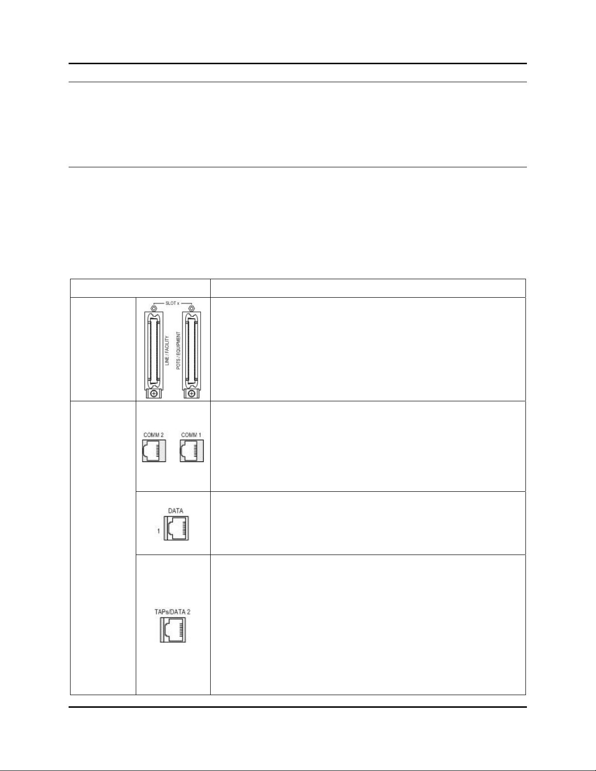
The MTAS-192 shelf has the following connectors. With the exception of the ground lug
(which is located on the side of the shelf), all connectors are located on the rear panel of
the shelf.
Table 7: Backplane Connector Functions of the MTAS-192 Shelf
Connector/Function Description
RJ-21
(8 sets)
RJ-45
24 Line/Facility and 24 POTS/Equipment Pairs
50-pin (25 pair) RJ-21 female connector – 1/ line card slot.
Pairings correspond to eight (8) splitter/TAU line card slots
#1-8 in the shelf.
COMM 1 and COMM 2 for ISCL Bus
RJ-45 shielded female jacks for COMM 1 communications
ports on top right and COMM 2 communications ports on
top left. Used for daisy chaining the ISCL bus from the
chassis (COMM 1 is ISCL bus OUT, COMM 2 is ISCL bus
IN).
DATA 1 for TAL Bus
RJ-45 shielded female jack for DATA 1 TAL extensions
port. Used to extend the TAL bus to the next shelf in a
daisy-chained network.
TAPs / DATA 2 port
RJ-45 shielded female jack. Test Access Link (TAL)
consisting of two 4-wire Test Access Paths (TAPs). Each
TAP delivers simultaneous metallic test access to both the
DSLAM and Line side of a port under test.
For a Stand-alone or master shelf configuration, this port is
used for connection to the test head.
For the slave shelf configuration, this port is the TAL input
connector for a daisy chain.
June 2006 Installation Guide
21
Page 28
Comtest Networks
CT-IG-MTAS192-2008-v1_8.doc
MTAS-192
Connector/Function Description
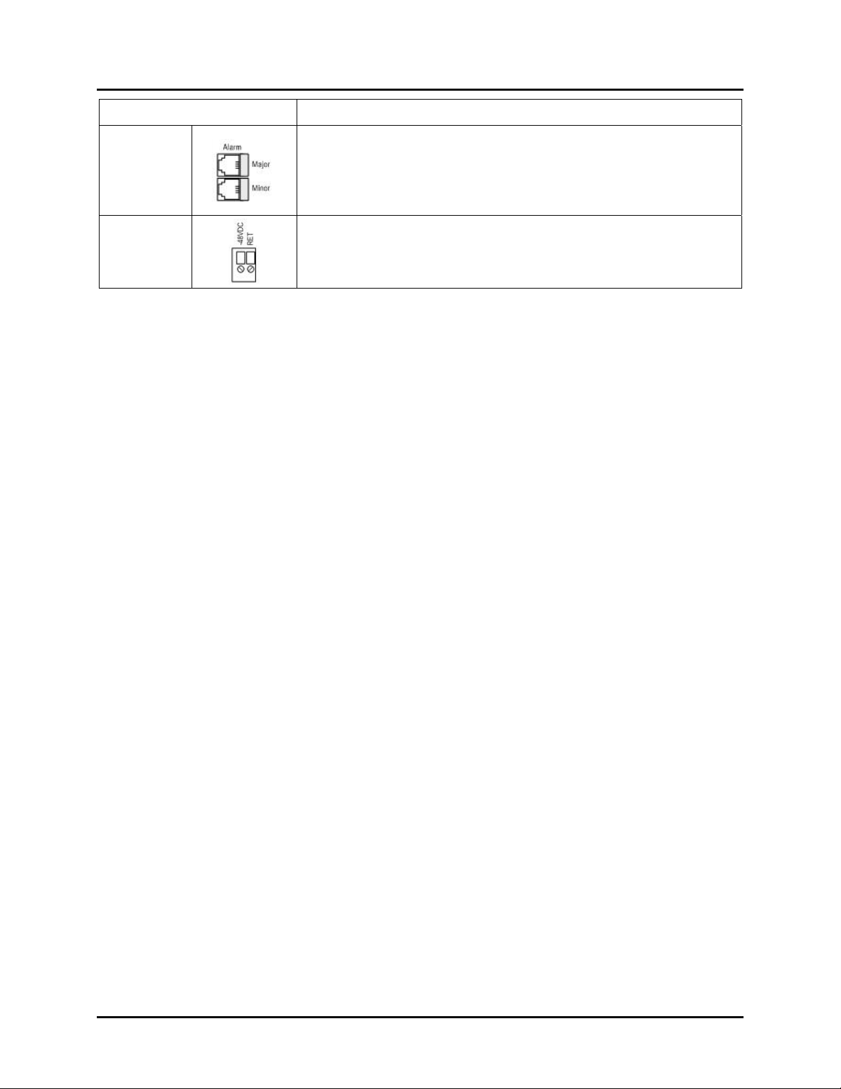
Major and Minor External Alarm Contacts
RJ-11
Dual Wire
Terminal
Header
RJ-11 female jack. Shelf Major and Minor Alarm outputs.
Normally open, dry contacts for visual and audible alarms.
Located on the top left of the chassis.
Shelf Power
Two sets of -48VDC Battery and Return terminals (for both
A and B power feeds), located on the left side.
22
Installation Guide June 2006
Page 29
CT-IG-MTAS192-2008-v1_8.doc
Comtest Networks
MTAS-192
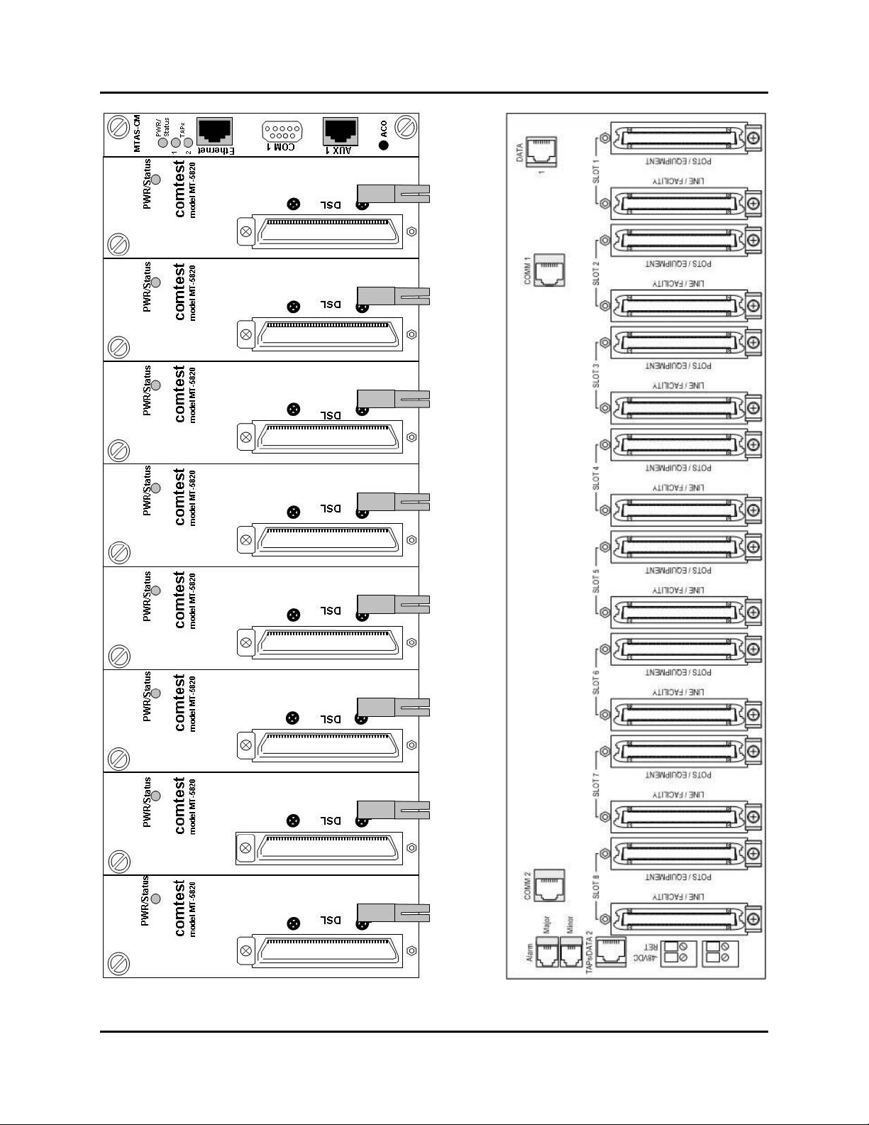
Figure 20: Front and Back Views of the MTAS-192 Shelf
June 2006 Installation Guide
23
Page 30
Comtest Networks
CT-IG-MTAS192-2008-v1_8.doc
MTAS-192
4.1.1 MTAS-CM Connectors
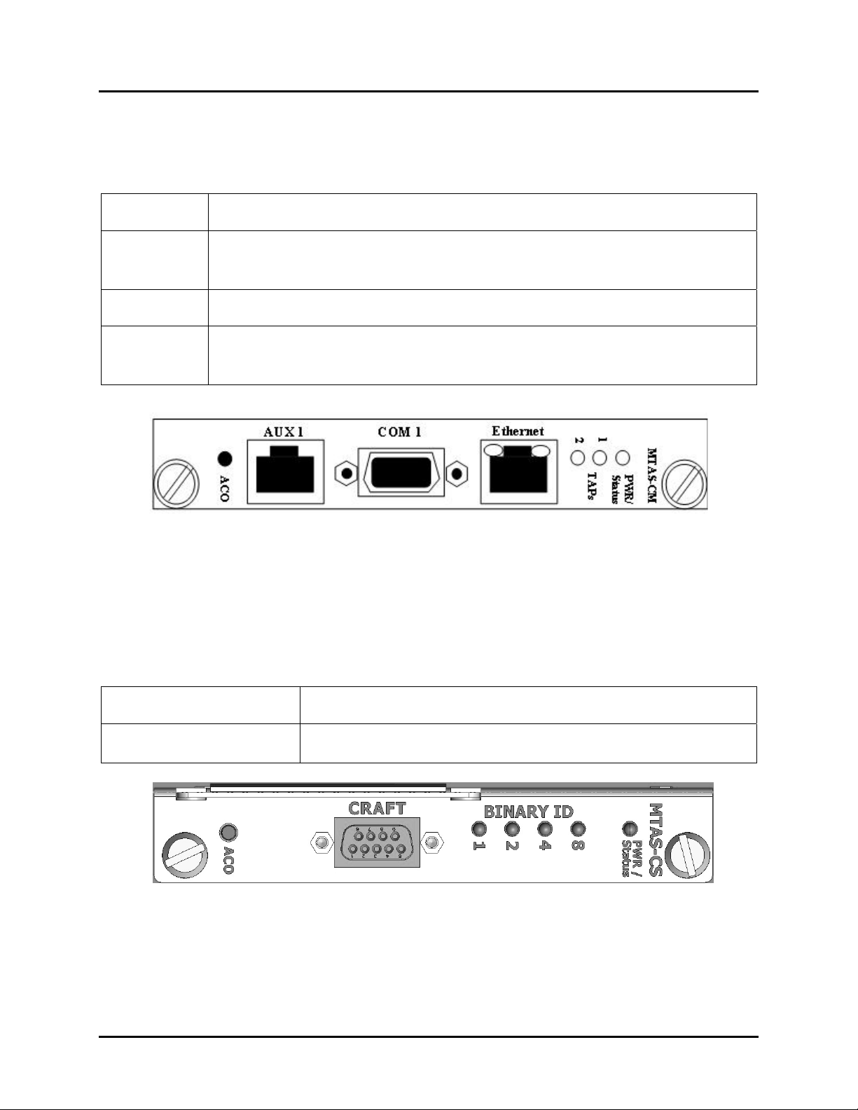
The MTAS-CM master shelf control card has three connectors.
Table 8: Connectors of the MTAS-CM
Connector Description
Ethernet
This shielded, female RJ-45 jack for 10/100 BaseT connection allows
TL1 communications with the MTAS-192 via telnet or direct TCP/IP
connection (master shelf only).
COM 1 This shielded, female DB-9 connector acts only as a debug port.
AUX 1
This shielded, female RJ-45 jack provides serial communication. The
device communicates at 9600 baud, with 8 data bits, 2 stop bits, no
parity and no flow control.
Figure 21: Master Shelf MTAS-CM Control Card Faceplate (Rotated 90 Degrees)
4.1.2 MTAS-CS Connectors
MTAS slave shelves have an MTAS-CS control card.
Table 9: Connectors of the MTAS-CS
Connector Description
CRAFT
A shielded, female DB-9 connector labeled as CRAFT acts
only as a debug port.
Figure 22: Slave Shelf MTAS-CS Control Card Faceplate (Rotated 90 Degrees)
24
Installation Guide June 2006
Page 31
CT-IG-MTAS192-2008-v1_8.doc
Comtest Networks
MTAS-192
4.1.3 xDSL Filter Card Connectors
The xDSL Splitter and Splitter with Test Access line cards have one female RJ-21
connector labeled "DSL".
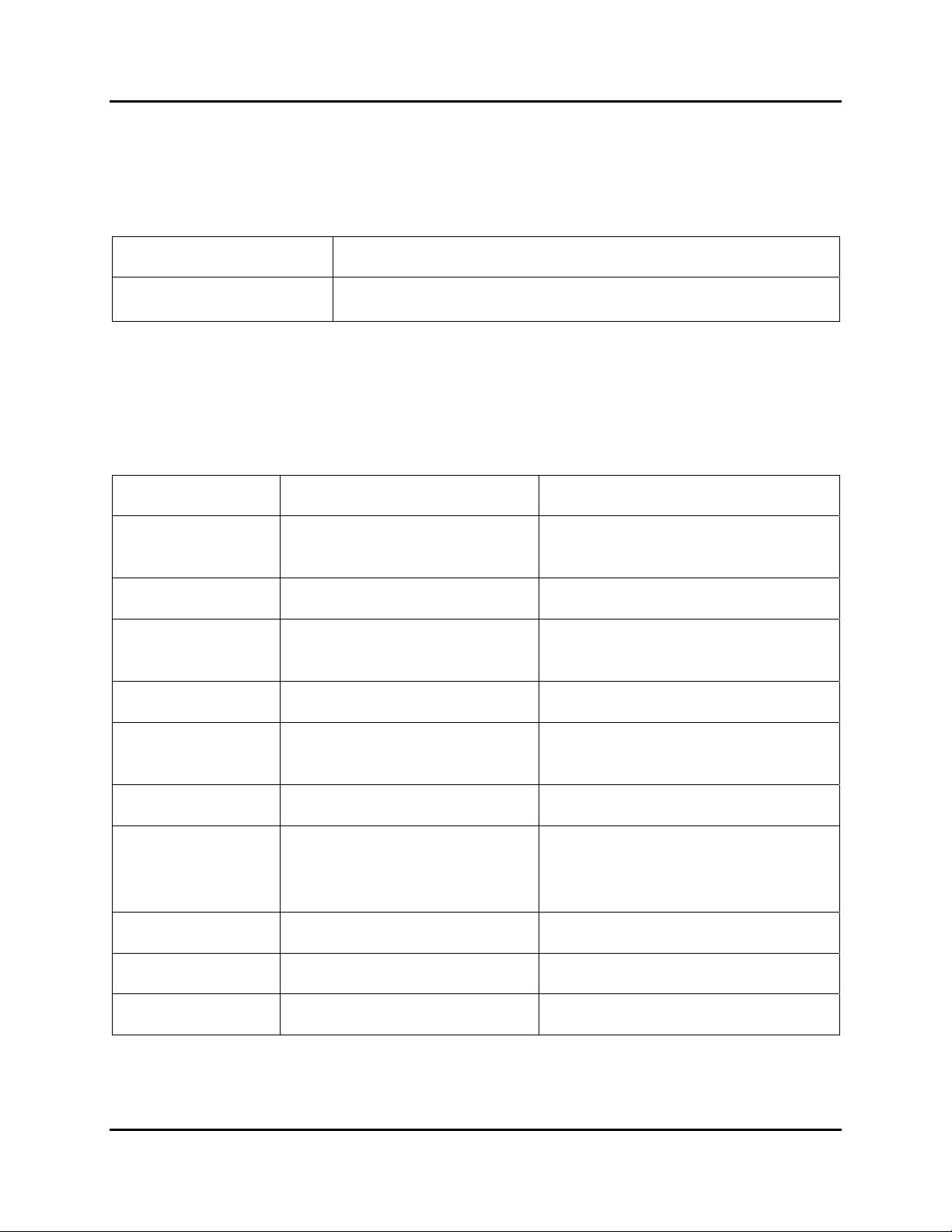
Table 10: Connectors of the xDSL Filter Cards
Connector Description
DSL
50-pin (25 pair) RJ-21 female connector – one per line card
slot - for connection to DSLAM.
4.2 Cabling
Refer to Table 11 for a summary of the recommended cables required for installation.
Table 11: MTAS-192 Shelf Cabling Requirements Summary
Interface Cable Requirements Recommendations
COMM 1 and
COMM 2
8-wire STP CAT5 STP CAT5 assembly
TAPs 8-wire UTP or STP CAT5 STP CAT5 recommended
DATA 1 and
DATA 2
8-wire UTP or STP CAT5 STP CAT5 recommended
Alarm Jacks 4-wire UTP CAT3 Normally open (NO) dry contacts
Power Terminal
Blocks
#16 - #18 AWG solid or
stranded copper wire
Fuse should be 0.5 Amp for
48 VDC circuit
Ground Screw #14 AWG solid copper wire
UTP or STP CAT5 or CAT3
RJ-21 Connectors
cable with non-shielded
housing. Minimum #26 AWG
to be used.
Ethernet 8-wire UTP or STP CAT5 STP CAT5 recommended
COM 1 For debug purposes only
AUX 1 8-wire UTP or STP CAT5 STP CAT5 recommended
June 2006 Installation Guide
25
Page 32
Comtest Networks
CT-IG-MTAS192-2008-v1_8.doc
MTAS-192
4.2.1 Grounding Connector
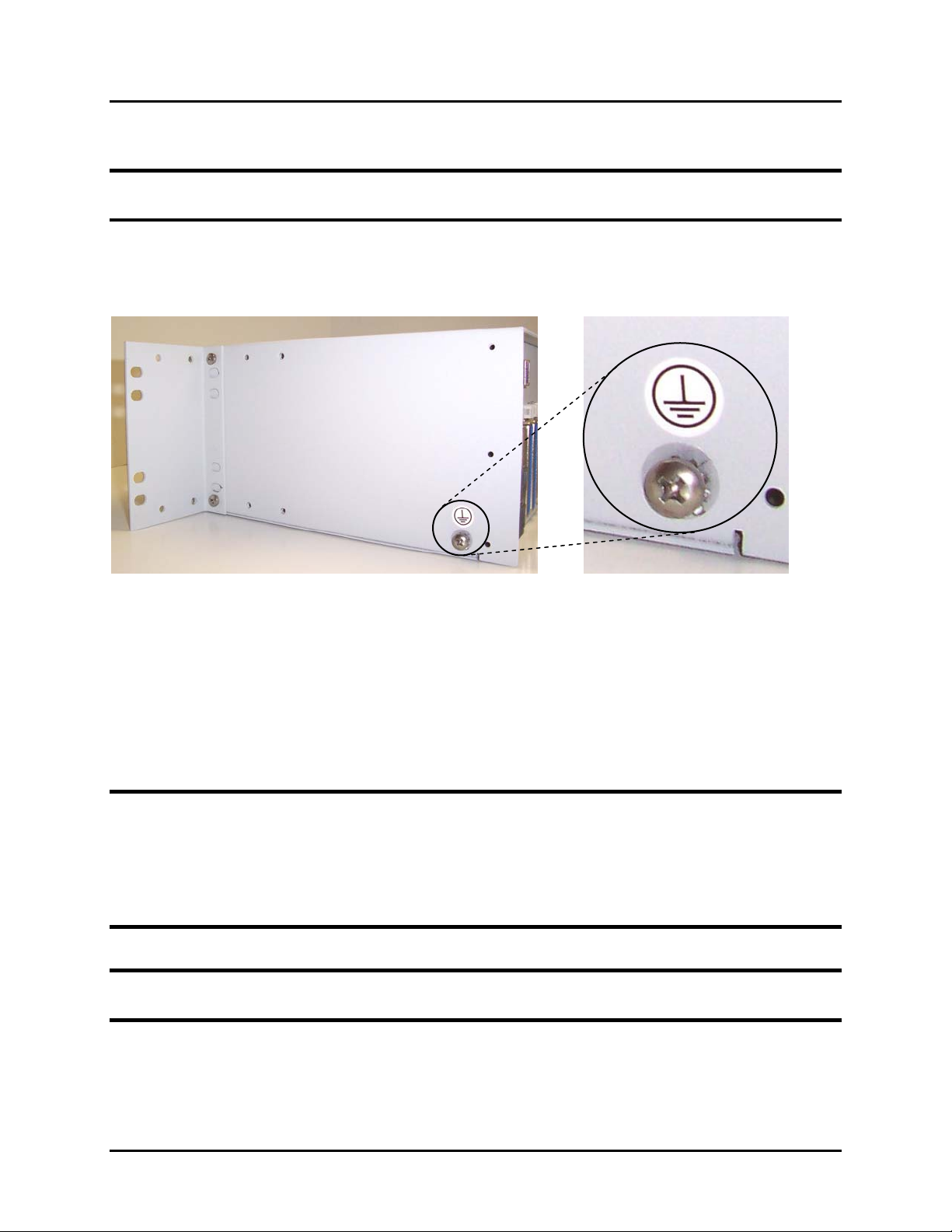
Note: Recommended wire size for the grounding connector is #14 AWG solid copper
wire.
Step 1. Screw the AWG #14 solid copper ground wire to the MTAS shelf chassis using
the grounding screw located on left side (viewed from rear) of the shelf.
Figure 23: Grounding Screw on Left Rear of MTAS Shelf
Step 2. Connect the other end of the ground cable to a known good earth ground. Be
sure to follow local and national electrical codes.
4.2.2 Power Feeds
WARNING: Do not switch on the power until the power connections are installed, and
the power cables are attached to the MTAS Shelf terminal block(s) power unit. Inserting
or removing the power unit while a live power cable is attached to it can result in
equipment damage and potentially life-threatening exposure to dangerous voltage
levels. Follow local electrical safety procedures and codes when making power source
connections.
Note: Recommended wire size for power feeds is #16 - #18 AWG solid or stranded
copper wire.
26
Installation Guide June 2006
Page 33
CT-IG-MTAS192-2008-v1_8.doc
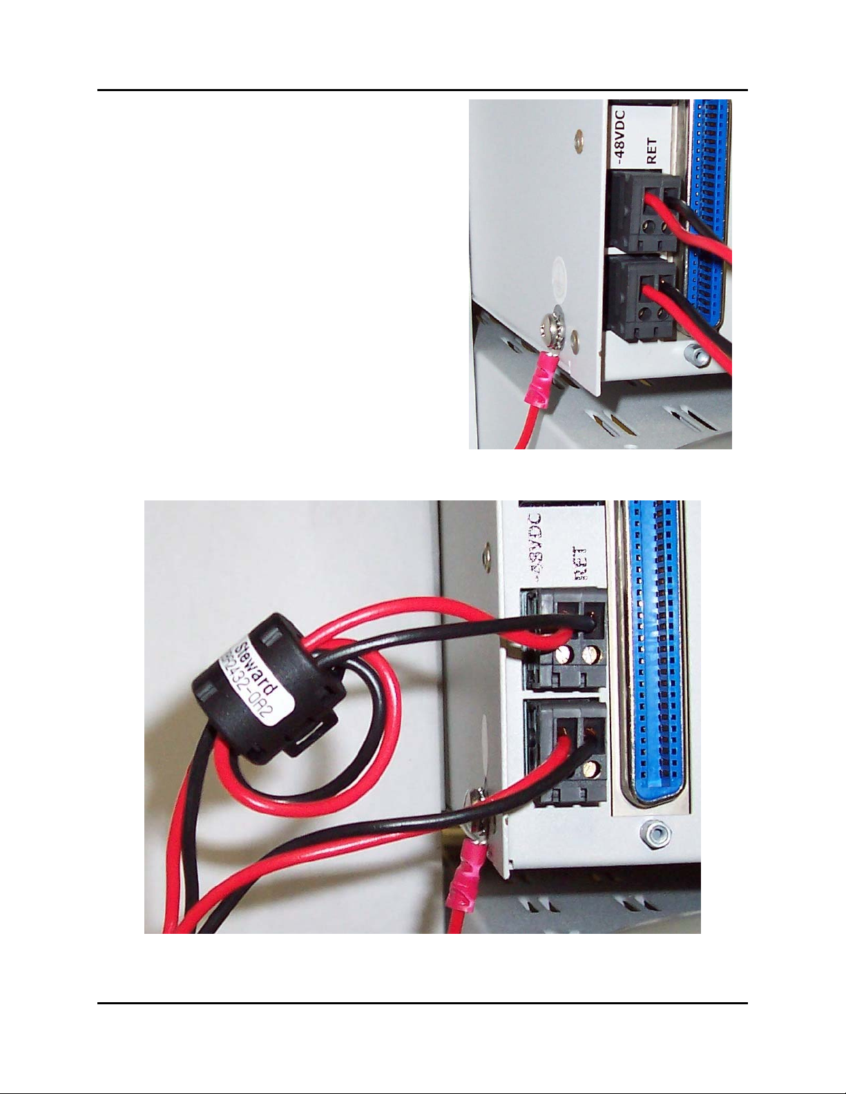
Step 1. Locate the -48VDC A and B power
feed connectors on the back of the
MTAS-192 shelf (left side).
Step 2. Connect AWG #16 solid copper wire
from the Power Distribution Bay to
the -48VDC connectors on the
MTAS-192 backplane dual wire
terminal header for Battery (-48VDC)
and Return (RET), for both A and B
power feeds if required.
Step 3. For the primary/A power feeds, form
a loop with both the -48VDC Battery
and Return feeds and push them into
an open Steward EMI suppressor,
then close the EMI suppressor.
Please see Figure 25. Repeat for the
redundant/B feed.
Step 4. Dress, tie, and label cables following
local procedures.
Figure 24: MTAS-192 Terminal Block
Comtest Networks
MTAS-192
Figure 25: Steward EMI Suppressor Closed around Power Cable
June 2006 Installation Guide
27
Page 34
Comtest Networks
CT-IG-MTAS192-2008-v1_8.doc
MTAS-192
4.2.3 Connecting Line/Facility and POTS/Equipment RJ-21 Connectors
NOTE: Please see Appendix A for cable pinouts.
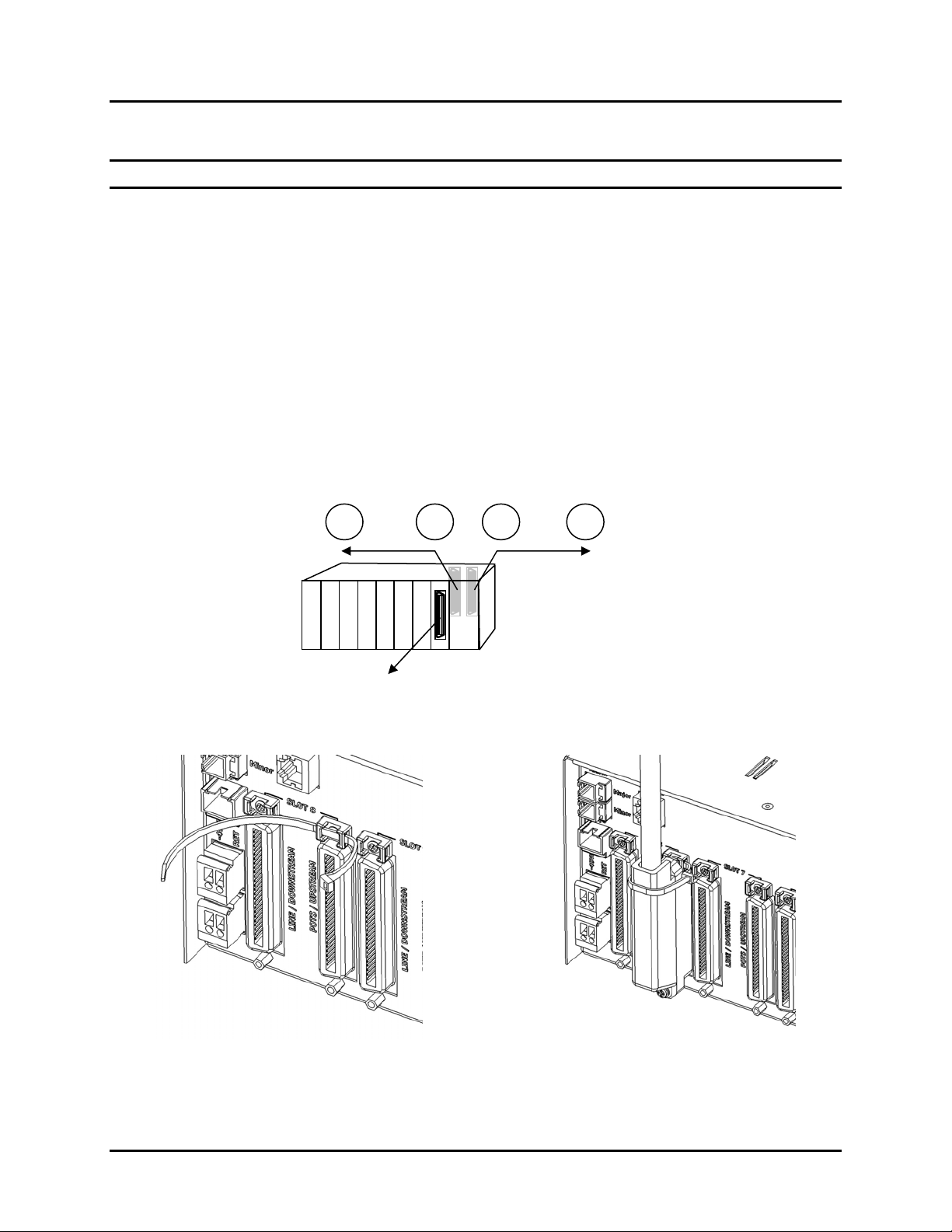
Step 1. Connect one end of the CAT3/5 24-pair cable to the "LINE/FACILITY" female
RJ-21 connector on the MTAS backplane. For right-angle RJ-21 connectors,
use a tie wrap to secure the top of connector to the cable tie mount and RJ-21
connector; use a screw for bottom. Please see Figure 27 and Figure 28.
Step 2. Connect the other end to the subscriber MDF.
Step 3. Connect one end of the CAT3/5 24-pair cable to the "POTS/EQUIPMENT"
female RJ-21 connector on the MTAS backplane.
Step 4. Connect the other end to the voice switch.
Step 5. Dress, tie, and label cables following local procedures.
Step 6. Repeat steps #1-5 for all provisioned line cards.
"LINE/FACILITY" to
subscriber
MDF
"POTS/EQUIPMENT" to
voice switch
12 3 4
"DSL" to DSLAM
Figure 26: Cabling RJ-21 Connections
Figure 27: Run Tie-wrap through Slot of Cable
Tie Mount
28
Installation Guide June 2006
Figure 28: Right Angle RJ-21 Male Connector
Tie-wrapped to Cable Tie Mount
Page 35
CT-IG-MTAS192-2008-v1_8.doc
Comtest Networks
MTAS-192
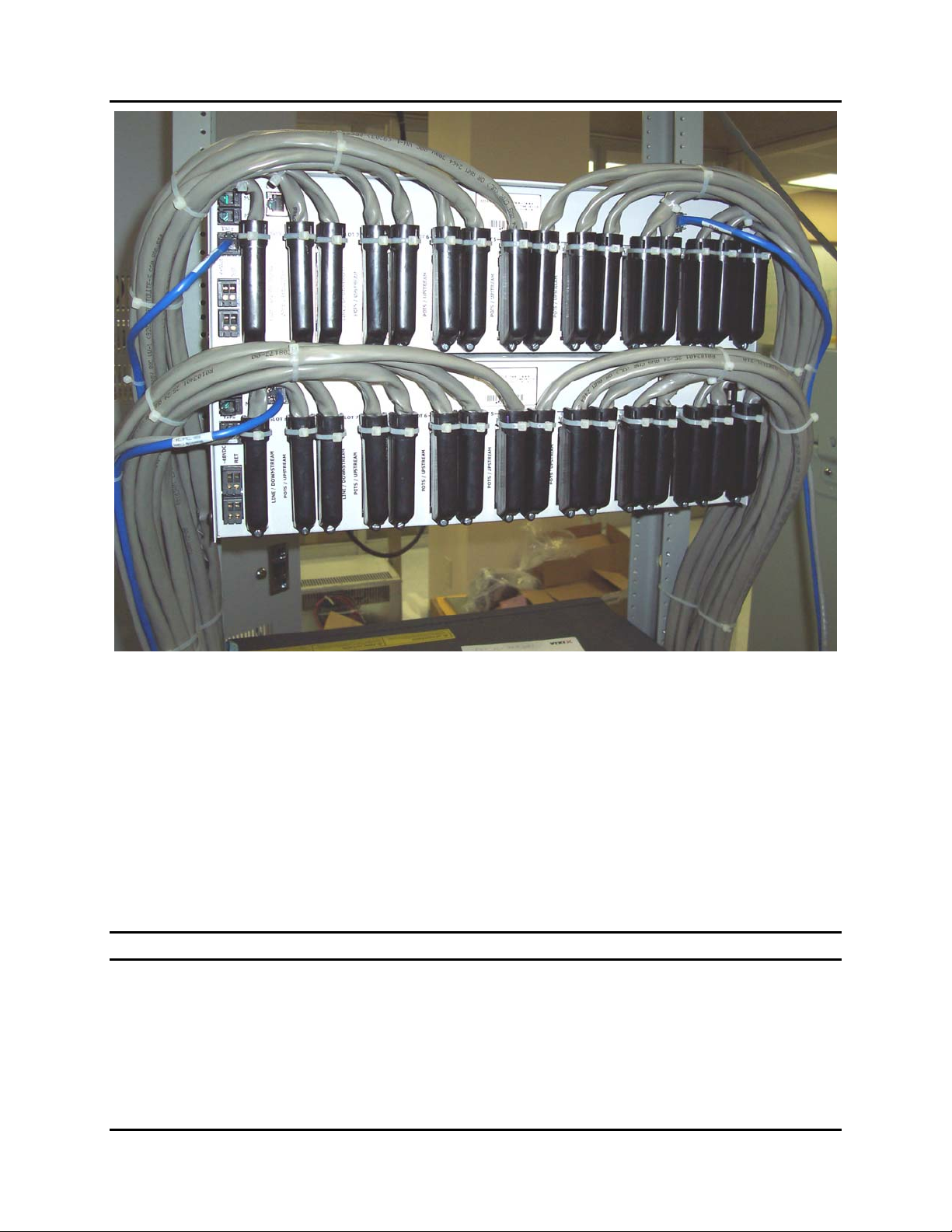
Figure 29: Two MTAS Shelves (Rear View) with CAT3 24-pair Cables using Right Angle
Connectors
4.2.4 Connecting to DSL
Step 1. Connect one end of the male CAT3/5 24-pair cable to the "DSL" female RJ-21
connector on the faceplate of each line card.
Step 2. Connect the other end to the DSLAM.
Step 3. Dress, tie, and label cables following local procedures.
Step 4. Repeat steps #1-3 for every cable connected to a line card.
NOTE: See the Appendix A, section 0: “RJ-21 Cabling” for cable pinouts.
June 2006 Installation Guide
29
Page 36

Comtest Networks
CT-IG-MTAS192-2008-v1_8.doc
MTAS-192
4.2.5 Connecting to the Control Card
There are three connectors on the control card faceplate providing communication with
the MTAS-192.
• Ethernet : A shielded RJ-45 jack allows communications with the MTAS-192 via
telnet (port 9090) or raw TCP/IP socket (port 9099).
• COM 1: A shielded, female DB-9 connector acts only as a debug port.
• AUX 1: A shielded, female RJ-45 jack provides serial communications. The device
communicates at 9600 baud, with 8 data bits, 2 stop bits, no parity and no flow
control.
NOTE: See Appendix A, sections 0: “Ethernet Cabling” and 0: “Serial Cabling” for cable
pinouts.
4.2.6 Connecting the Test Head to the MTAS-192 Shelf
Step 1. Connect the test head to the MTAS via the TAPs (Test Access Paths/Link)
shielded RJ-45 jack on the left side of the MTAS backplane using the TAL
custom cable built per Appendix A, section 0: “Test Access Link (TAL) Bus
Extender”.
NOTE: For dual test head operation, the far end of the cable must be split and
terminated on a terminal block that will allow access to the two internal TAP buses, TAP
1 and TAP 2, one for each test head.
4.2.7 Daisy-chaining Multiple MTAS-192 Shelves
Up to 12 MTAS shelves may be daisy-chained together. There is one master MTAS
shelf and there can be up to 11 slave MTAS shelves, for a total of 12 MTAS shelves.
Connecting them are two types of MTAS buses: the Test Access Link (TAL) extender
bus (master DATA 1 to slave TAPs/DATA 2 connector) and ISCL bus (master COMM 1
to slave COMM 2 connector).
NOTE: Ensure that MTAS-CM control card is configured as chassis ID=0 (Factory
default setting). Configure each slave (MTAS-CS) control card with a unique chassis
(shelf) ID between 1 and 11, for each master/slave group of 12 MTAS shelves to which
it belongs. Check the DIP switch settings in the MTAS Control Card Address DIP
switch Settings table (Table 15) in Appendix A (section 0: “MTAS Control Card Shelf
Address DIP Switch Settings”) to ensure that the shelf is configured correctly. There is
no requirement to set the switches to correspond to the PHYSICAL position in the
daisy-chain.
30
Installation Guide June 2006
Page 37
CT-IG-MTAS192-2008-v1_8.doc
Comtest Networks
MTAS-192
NOTE: See Appendix A, section 0: “Test Access Link (TAL) Bus Extender” for cable
pinouts.
NOTE: Ensure all 8-wire CAT5 shielded cables are properly terminated to earth ground
using a shielded RJ-45 plug.
4.2.7.1 Test Access Link (TAL) Bus Extender
Step 1. Using 8-wire, CAT5 cable (see Appendix A, section 0: “Test Access Link (TAL)
Bus Extender” for pinouts/cable assembly), connect the test head to the master
MTAS shelf via the female TAPs/DATA 2 RJ-45 jack .
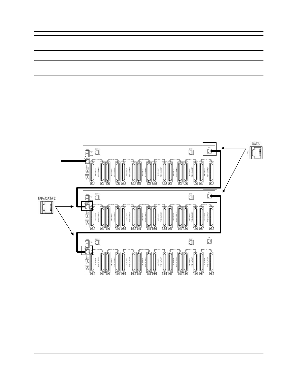
Step 2. Connect the female DATA 1 RJ-45 jack on the MTAS backplane to the female
TAPs/DATA 2 jack on the next (slave) MTAS shelf.
Step 3. Repeat for all shelves in the daisy -chain.
To test
head
Master Shelf
(Chassis ID=0)
Slave Shelf
(Unique Chassis
ID=1-11)
Slave Shelf
(Unique Chassis
ID=1-11)
Figure 30: Daisy Chaining using TAL Bus Extenders (One Master, Two Slave Shelves)
4.2.7.2 Inter-Shelf Communications Link (ISCL) Bus Extender
Step 4. Using shielded, 8-wire CAT 5 Ethernet cable (see Appendix A, section 0:
“Inter-Shelf Communications Link (ISCL) Cabling” for pinouts and cable
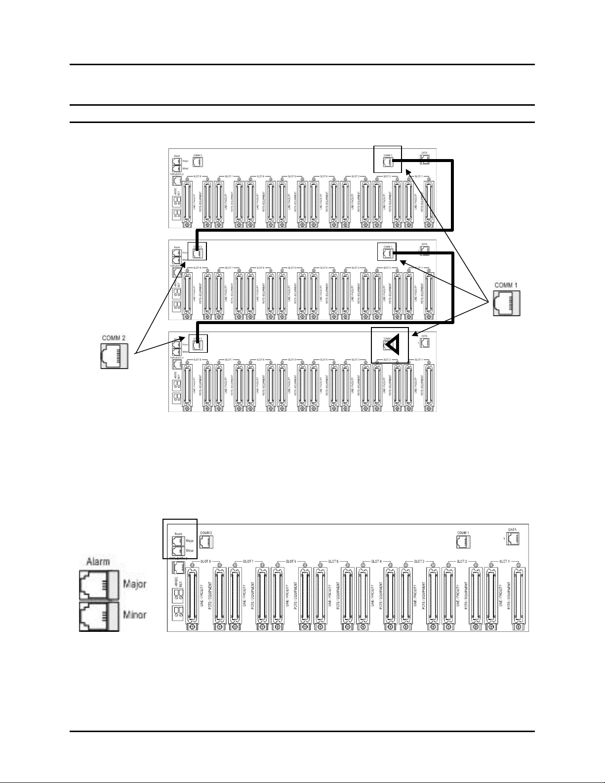
assembly), connect COMM 1 on the master MTAS shelf to COMM 2 on the
next slave shelf.
Step 5. Repeat for all shelves in the daisy -chain.
June 2006 Installation Guide
31
Page 38
Comtest Networks
CT-IG-MTAS192-2008-v1_8.doc
MTAS-192
Step 6. On the last shelf, terminate the COMM 1 port with the ISCL terminator.
NOTE: Total ISCL bus length for the entire chain must not exceed 400 feet.
Master Shelf
(Chassis ID=0)
Slave Shelf
(Unique Chassis
ID=1-11)
Slave Shelf
(Unique Chassis
ID=1-11)
Figure 31: Daisy Chaining the ISCL Bus (Bus Terminator on COMM 1, Last Shelf)
4.2.8 Connecting MAJOR and MINOR Alarm Ports
If required, connect the female RJ-11 jack alarm ports, MAJOR and MINOR, to the
appropriate alarm block on the bay/equipment rack, per local methods and procedures.
See Appendix A, section 0: “Alarm Cabling” for Alarm Descriptions.
Figure 32: Major and Minor Alarm Ports
# # #
32
Installation Guide June 2006
Page 39
CT-IG-MTAS192-2008-v1_8.doc
Comtest Networks
MTAS-192
Chapter 5
Activation and Testing
5.1 Introduction
This chapter describes how to power up the MTAS-192 shelf and verify that it is
operating correctly, after all required physical installation of the MTAS shelf, circuit
packs, and associated cabling has been completed as described in the preceding
chapters.
5.2 Powering the MTAS-192
Apply power to the MTAS shelf by inserting the fuse corresponding to the MTAS shelf at
the Power Distribution Block at the top of the rack. (See Appendix A MTAS
Specifications for fuse requirements). For redundant power, remember to insert the
corresponding A and B feed fuses.
5.3 Validating Operation of Control Cards and Line Cards
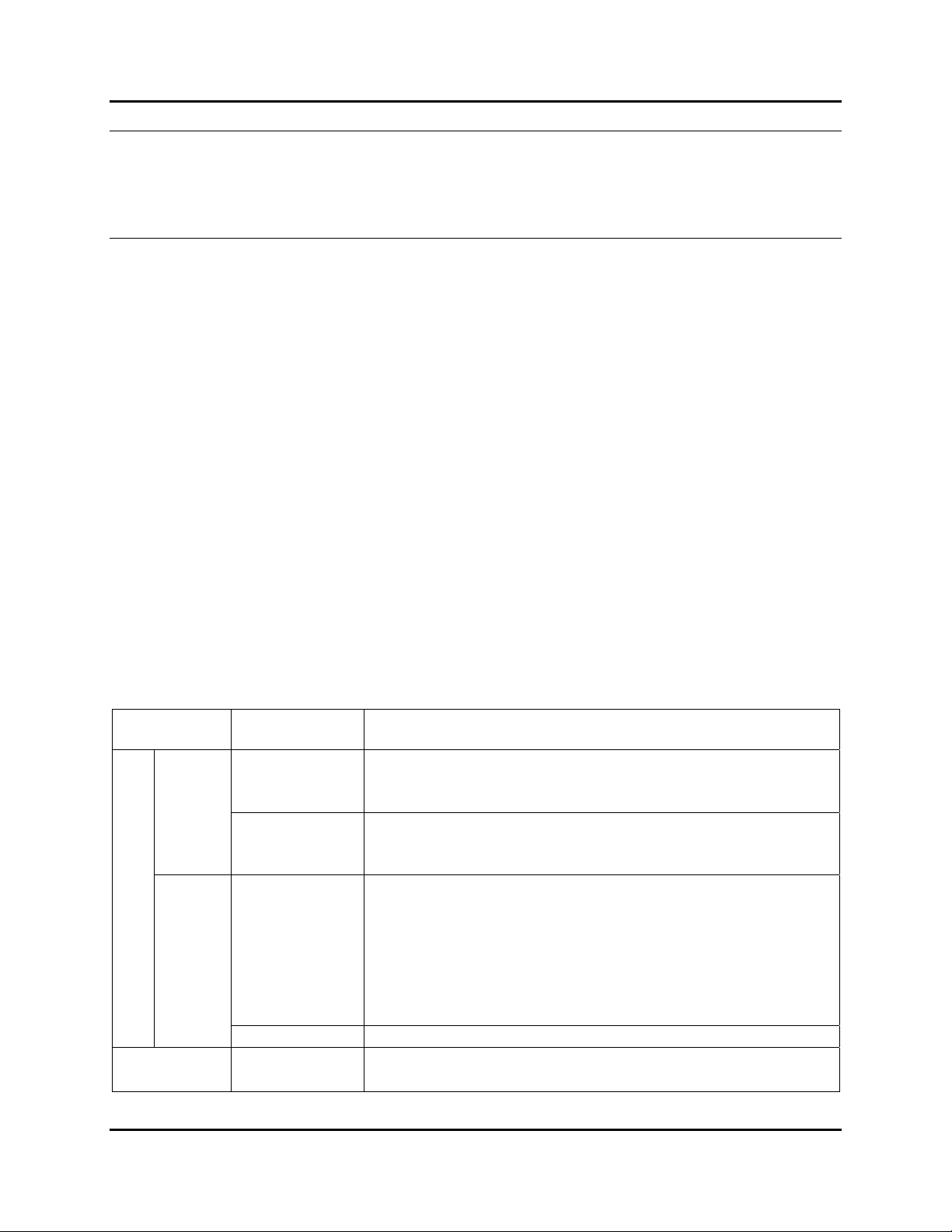
After applying power to the MTAS-192 shelf, the Light Emitting Diodes (LEDs) on the
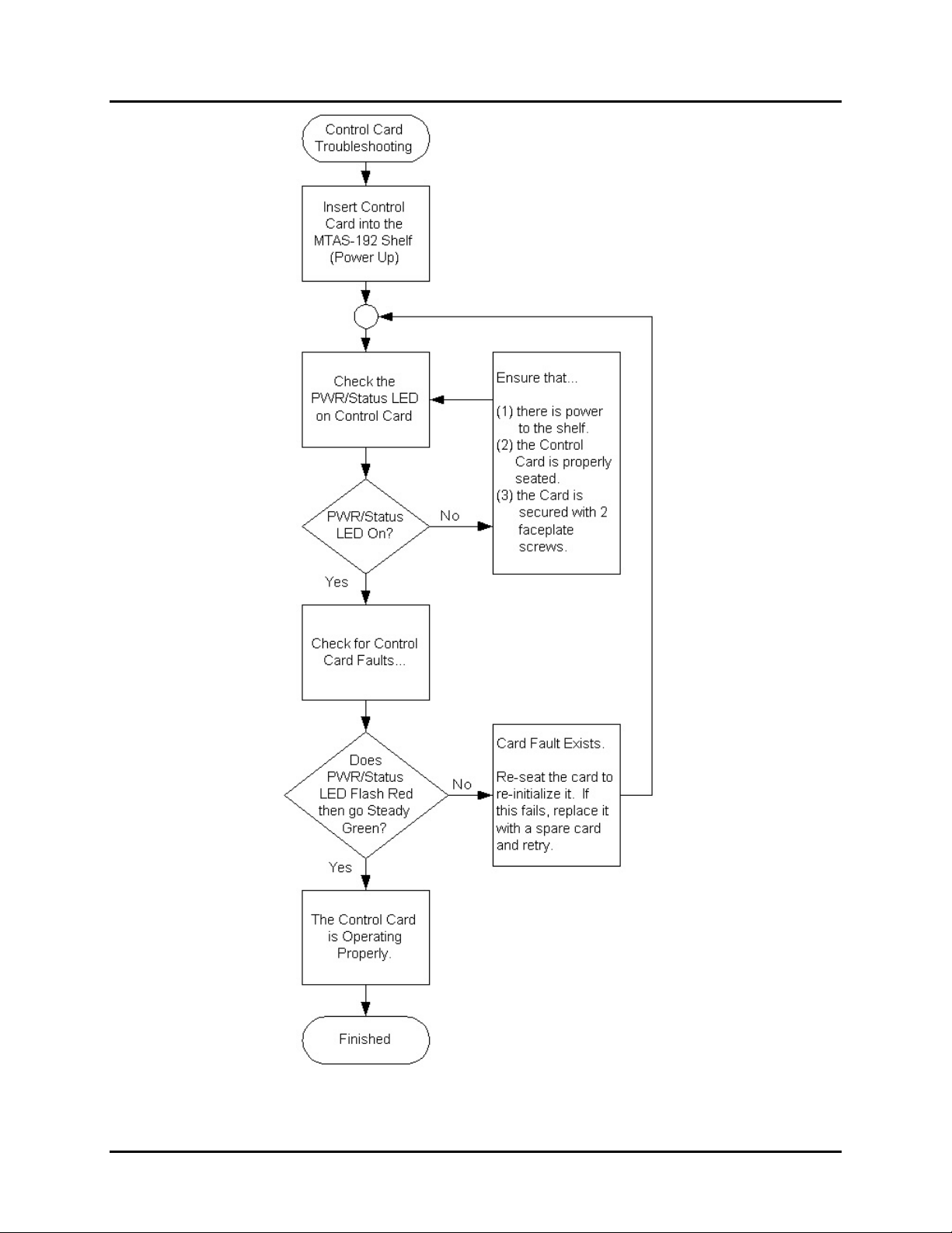
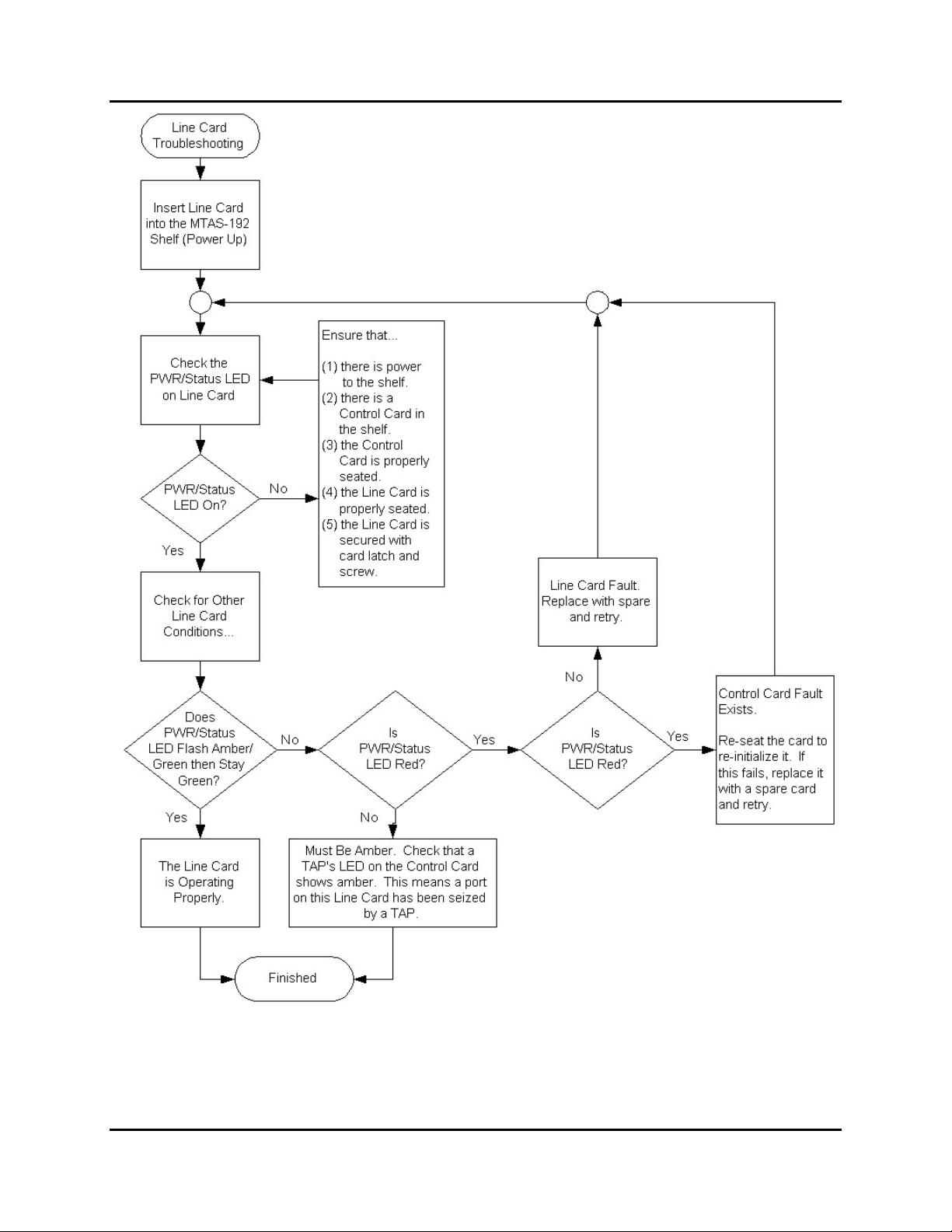
card faceplates should behave as listed in Table 12. Figure 33 and Figure 34 show
flowcharts for validating operation of these cards.
Table 12: LED Operation after Successful Power Up
Cards LEDs LED Action After Power Up
PWR/Status
Master
Shelf
TAPs 1 and 2
Control Cards
Slave
Shelf
Line Cards PWR/Status
PWR/Status
Binary ID Indicates configured chassis ID.
Immediately light solid red, then after a few seconds
light solid green.
Immediately light solid red, then after a few seconds
light solid green.
Immediately flash red for several seconds, then light
solid amber. This LED will remain amber until it is
discovered by the master shelf (typically 30 seconds),
at which time it will light solid green and each line card
will be then be restarted, processing from left to right,
with its PWR/Status LED lighting – flashing amber for a
few seconds, then solid green.
Flicker amber until the card can read a valid chassis ID,
then light solid green.
June 2006 Installation Guide
33
Page 40
Comtest Networks
MTAS-192
CT-IG-MTAS192-2008-v1_8.doc
Figure 33: Control Card Flowchart for Validating Operation
34
Installation Guide June 2006
Page 41
CT-IG-MTAS192-2008-v1_8.doc
Comtest Networks
MTAS-192
Figure 34: Line Card Flowchart for Validating Operation
June 2006 Installation Guide
35
Page 42

Comtest Networks
CT-IG-MTAS192-2008-v1_8.doc
MTAS-192
5.4 Communicating with the MTAS
All user access is via the Master MTAS shelf. Communications with the MTAS master
shelf is provided via the Ethernet port or AUX 1 (serial) port on the MTAS-CM Card.
NOTE: You must configure the IP settings for the master shelf prior to connecting it to
your Local Area Network (LAN). Failure to do so may result in degraded LAN
performance or an outage.
5.4.1 Via the Ethernet Port
Connect to the Ethernet jack on the MTAS-CM control card using a straight-through
10/100BaseT Ethernet cable or connect your PC directly to the MTAS Ethernet port
using a cross-over cable, as described in Appendix A.
To log in, follow the steps below.
Step 1. From the PC, launch the command prompt screen by doing the following: (1)
Click on the START button (lower, left side of screen), (2) Select “RUN…” from
the menu, (3) Type cmd in the “Open” field of the RUN dialogue box, and (4)
click the OK button.
Step 2. At the command line, type telnet xx.xx.xx.xx 9090 where xx.xx.xx.xx is the
static IP address and 9090 is the telnet port.
The TL1>> prompt will then be displayed on the screen.
5.4.2 Via the Serial Port
Step 1. Configure your PC's VT emulation software (e.g., Hyperterminal, ProCOMM
Plus, etc.) or VT terminal Setup Directory to allow access to the MTAS shelf.
Settings are: 9600 baud, with 8 data bits, 2 stop bits, no parity and no flow
control.
Step 2. Using a serial cable constructed per the pin out diagram in Appendix A,
connect one (male) end to the AUX 1 jack on the MTAS-CM control card.
Step 3. Connect the other (male) end to the serial port on your PC, using an RJ-45 to
DB-9 adapter. See Table 21: Pin Layout for Serial RJ-45 → DB-9 Adapter in
Appendix A, section 0: “Serial Cabling” for proper pinout information.
Step 4. Press ENTER in the terminal software. The operator should then see the
TL1>> prompt on the screen.
36
Installation Guide June 2006
Page 43
CT-IG-MTAS192-2008-v1_8.doc
Comtest Networks
MTAS-192
5.5 IP Network Configuration
IP addresses are used to route packets from place to place on an intranet/internet. If
you are not part of an established network, and your Ethernet segment is isolated, e.g.,
using an isolated Ethernet hub, you can choose "private" addresses from one of the
reserved ranges of three different classes: A, B, and C.
Table 13: Reserved Private IP Address Ranges for Classes A, B, and C
Class Minimum Address Maximum Address
A 10.0.0.0 10.255.255.255
B 172.16.0.0 172.31.255.255
C 192.168.0.0 192.168.255.255
The MTAS-CM is preconfigured with the following network address.
• IP Address: 10.0.2.100
• Subnet Mask: 255.255.255.0
• Gateway: 10.0.2.20
To change the IP address of the MTAS-CM, the user must be logged in to the TL1
command interface as specified in Section 5.4 Communicating with the MTAS. At the
TL>> prompt, the user can change the network settings using the following procedure.
Step 1. Login from the PC using TL1 command ACT-USER.
ACT-USER::ROOT:1::PUBLIC;
“ROOT” is the system administrator User ID (UID) and “PUBLIC” (in capital
letters) is the default password.
NOTE: To prevent unauthorized access, change your password as soon as possible
and store this password in a safe place.
On success, the user should see something similar to:
MTAS_106 70-01-01 00:39:38
M 1 COMPLD
“UID=ROOT:LASTLOGIN=Thu Jan 1 00:28:41 1970,UNSUCCESSFULATTEMPTS=0”
;
And a TL1 prompt.
TL1>>
At the TL1 prompt, type the following command:
June 2006 Installation Guide
37
Page 44

Comtest Networks
MTAS-192
CONN-CLI:::1;
The response should be as follows:
Welcome to the MTAS CLI
For a list of commands, enter ‘?’
At this point, the user can type:
chk ethernet
This will display the existing settings for the MTAS-CM. To change the
settings, type the following:
ethernet
A series of settings and prompts will be displayed.
IP Address 10.0.2.100
New?
The user can either enter a new IP address or press <return> to keep the
existing value. The next prompt will be displayed.
Network Mask 255.255.255.0
New?
The user can either enter a new network mask or press <return> to keep the
existing value. The next prompt will be displayed.
Gateway 10.0.2.20
New?
The user can either enter a new gateway address or press <return> to keep
the existing value. The next prompt will be displayed.
DNS Server 0.0.0.0
New?
The user can either enter a new DNS server address or press <return> to keep
the existing value. The following message should appear and the user should
then log out.
IP Address 10.0.2.100
Network Mask 255.255.255.0
Gateway 10.0.2.20
DNS Server 0.0.0.0
Change will take effect on reset
CT-IG-MTAS192-2008-v1_8.doc
38
Installation Guide June 2006
Page 45

CT-IG-MTAS192-2008-v1_8.doc
Comtest Networks
MTAS-192
To manually reset the system for the changes to take effect, the user must
type the following command.
system reset
Otherwise, the new IP settings will not take effect until the system is restarted.
NOTE: For a detailed description of TL1 commands and command syntax, refer to the
MTAS TL1 Guide.
NOTE: For information on using the MTAS after successful installation, refer to the
MTAS-192 User Guide CT-UG-MTAS192-2005.
# # #
June 2006 Installation Guide
39
Page 46

Comtest Networks
MTAS-192
CT-IG-MTAS192-2008-v1_8.doc
40
Installation Guide June 2006
Page 47

CT-IG-MTAS192-2008-v1_8.doc
Comtest Networks
MTAS-192
Appendix A
Specifications
MTAS-192 Specifications
Table 14: MTAS-192 Specifications
Item Description
Dimensions 3 rack unit high chassis (H x W x D = 5.22" x 17.3" x 10.5")
Mounting 19" or 23" rack-mountable
Chassis Capacity 192 (2-wire) circuit packs
Line Card Capacity
Line Card Functionality
Options
Slots
Impedance
Line Card
Compliances
Test Access Capacity
Each line card contains 24 2-wire circuit ports. Up to 8 line
cards can be installed in a chassis.
Test Access only to data or POTS circuits
Splitter only
Splitter plus test access
8 available for line cards (#1-8)
1 available slot for control module card (#9)
North American : 900-600 ohms
ETSI European Harmonized
MT-5820 and NA-5820 line cards:
T1.413, G.992.1, G.992.3, G.992.5
EU-5807 line card:
TS 101 952-1-1, TS 101 952-1-2
2 four-wire test buses per chassis or daisy-chained system.
Each bus carries both the DSLAM/EQUIPMENT side and
the LINE/FACILITY side of the port under test.
June 2006 Installation Guide
41
Page 48
Comtest Networks
CT-IG-MTAS192-2008-v1_8.doc
MTAS-192
Item Description
LINE (local) loop: 50-pin (25 pair) standard Telco RJ-21
connector (backplane, one per line card)
POTS: 50-pin (25 pair) standard Telco female RJ-21
Interfaces3
connector (backplane, one per line card)
DSL: 50-pin (25 pair) standard Telco female RJ-21
connector (faceplate of each line card)
TEST ACCESS BUS: 8-wire RJ-45 female jack (backplane)
Ethernet - 10/100BaseT Shielded RJ-45 (Supports ASCII
and TL1 messaging (GR-834))
Communications
COM 1- RS232 serial port - DB-9 connector debug port
AUX 1 - RS232D serial port – shielded RJ-45 connector
(Supports ASCII and TL1 messaging (GR-834))
TELNET 9090
TCP/IP Ports
RAW TCP SOCKET 9099
Control Options TL1, ASCII (command line, Telnet, TCP)
Protection
Secondary protection on POTS/EQUIPMENT side via
current and over-voltage devices
Compliance UL/CSA, FCC Part 68, CS 03, NEBS, GR1089, CE
Power Standard CO Battery, -48V DC operation
Current 250-500 mA (0.5 A) for a fully-loaded shelf
Fuse Requirements 0.5 Amp minimum to 1.0 Amp maximum
Environment -40 to +60 degrees Celsius
3
Only 24 pairs are used on the RJ-21 connector. See Appendix A for pinout information.
42
Installation Guide May 2008
Page 49
CT-IG-MTAS192-2008-v1_8.doc
MTAS Control Card Shelf Address DIP Switch Settings
Table 15: MTAS Control Card Shelf Address DIP Switch Settings
Physical Setting Binary ID
MTAS Shelf #1 #2 #3 #4 8 4 2 1
MTAS-CM master Down Down Down Down 0 0 0 0
MTAS-CS slave #1 Down Down Down Up 0 0 0 1
MTAS-CS slave #2 Down Down Up Down 0 0 1 0
MTAS-CS slave #3 Down Down Up Up 0 0 1 1
MTAS-CS slave #4 Down Up Down Down 0 1 0 0
MTAS-CS slave #5 Down Up Down Up 0 1 0 1
MTAS-CS slave #6 Down Up Up Down 0 1 1 0
Comtest Networks
MTAS-192
MTAS-CS slave #7 Down Up Up Up 0 1 1 1
MTAS-CS slave #8 Up Down Down Down 1 0 0 0
MTAS-CS slave #9 Up Down Down Up 1 0 0 1
MTAS-CS slave #10 Up Down Up Down 1 0 1 0
MTAS-CS slave #11 Up Down Up Up 1 0 1 1
The DIP switch settings may be verified by physical inspection or by viewing the slave
card faceplate Binary ID LEDs.
If DIP switch settings are duplicated in the daisy chain, between master and slave, or
between two slaves, these cards will go into alarm.
NOTE: For DIP switch settings, a logical 0 is represented by having the DIP switch in
the DOWN position. A logical 1 is represented by having the DIP switch in the UP
position. Please refer to Figure 18: MTAS-CM (Control Master) DIP Switch Location
and Figure 19: MTAS-CS (Control Slave) DIP Switch Location.
June 2006 Installation Guide
43
Page 50

Comtest Networks
CT-IG-MTAS192-2008-v1_8.doc
MTAS-192
Test Access Link (TAL) Bus Extender
The Test Access Link (TAL) is used for the following connections:
• To connect the test head to the Master MTAS shelf via the TAPs/DATA 2 RJ-45
connector.
• To extend the TAL bus to multiple chassis in a daisy-chain configuration via the
DATA 1 and TAPs/DATA 2 RJ-45 connectors.
For daisy-chain configurations, the TAL bus is extended from one chassis to the next by
connecting the DATA 1 (OUT) RJ-45 connector of one shelf to the TAPs/DATA 2 (IN)
RJ-45 connector of the next shelf until the last shelf of the daisy chain has been
connected as shown in Figure 30 (which shows one master and two slave shelves).
The TAL bus extender cabling sequence for a full daisy-chained system (12 chassis) is
listed in Table 16.
Table 16: TAL Bus Extender Cabling Sequence
Connect from: To:
Test Head Master TAPs / DATA 2
Master DATA 1 Slave 1 TAPs / DATA 2
Slave 1 DATA 1 Slave 2 TAPs / DATA 2
Slave 2 DATA 1 Slave 3 TAPs / DATA 2
Slave 3 DATA 1 Slave 4 TAPs / DATA 2
Slave 4 DATA 1 Slave 5 TAPs / DATA 2
Slave 5 DATA 1 Slave 6 TAPs / DATA 2
Slave 6 DATA 1 Slave 7 TAPs / DATA 2
Slave 7 DATA 1 Slave 8 TAPs / DATA 2
Slave 8 DATA 1 Slave 9 TAPs / DATA 2
Slave 9 DATA 1 Slave 10 TAPs / DATA 2
Slave 10 DATA 1 Slave 11 TAPs / DATA 2
Slave 11 DATA 1
TAL Custom Cabling
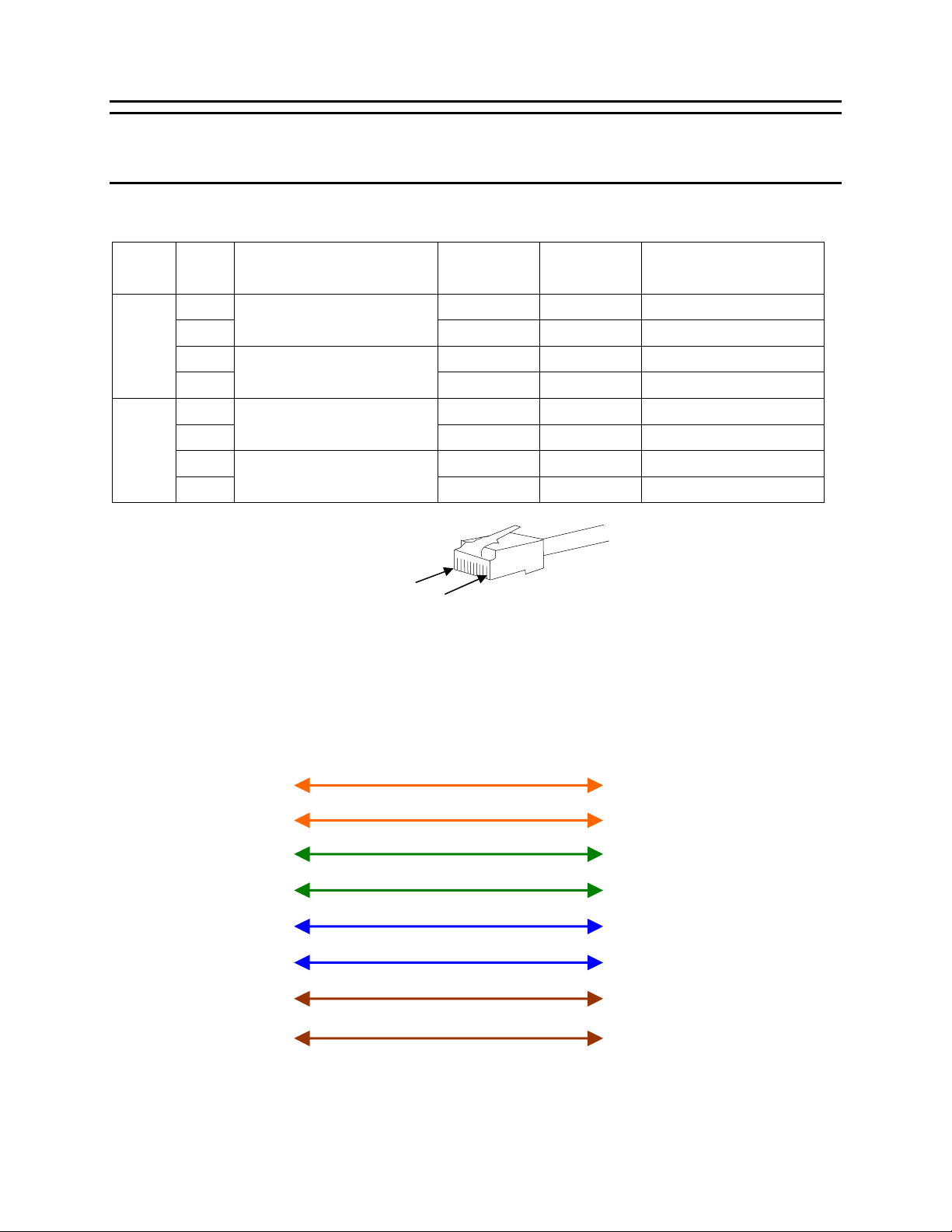
The TAL cable must be wired as shown in Table 17 and Figure 36. Comtest
recommends that shielded cable be used for the TAL installation. The TAPS/DATA 2
and DATA 1 RJ-45 jacks are shielded and tied to the chassis ground to accommodate
shielded RJ-45 plugs.
44
Installation Guide May 2008
Page 51
CT-IG-MTAS192-2008-v1_8.doc
Comtest Networks
MTAS-192
IMPORTANT: If using shielded cable, ensure that devices on either end of the cable
have the same reference ground (earth/chassis/frame ground) in order to prevent
ground loops.
Table 17: Cable Pinouts for TAL Bus Extender
TAP # Pin # Label
( 2-Wire )
1 TxA Tip Orange/White
LINE/FACILITY (AF)
2
TAP 1
3 RxA Tip Green/White
DSLAM/EQUIPMENT (AE)
4
5 RxB Tip Blue/White
LINE/FACILITY (AF)
6
TAP 2
7 TxB Tip Brown/White
DSLAM/EQUIPMENT (AE)
8
Figure 35: Pin Locations for Test Access Link Connector
Pin #1
Pin #8
CAT 5e Shielded Cable
Label
Tip/Ring Colour coding
( 4-Wire )
TxA Ring Orange
RxA Ring Green
RxB Ring Blue
TxB Ring Brown
Orange/White
Orange
Green/White
Green
Blue/White
Blue
Brown/White
Brown
Master Data 1
RJ-45 shielded
Male Connector
(Plug)
1
2
3
4
5
6
7
8
Figure 36: Pinouts and Cable Colors for Custom TAL Bus Extender Cable
June 2006 Installation Guide
1
2
Slave 1 TAPs / DATA 2
3
RJ-45 shielded
Male Connector
(Plug)
4
5
6
7
8
45
Page 52
Comtest Networks
CT-IG-MTAS192-2008-v1_8.doc
MTAS-192
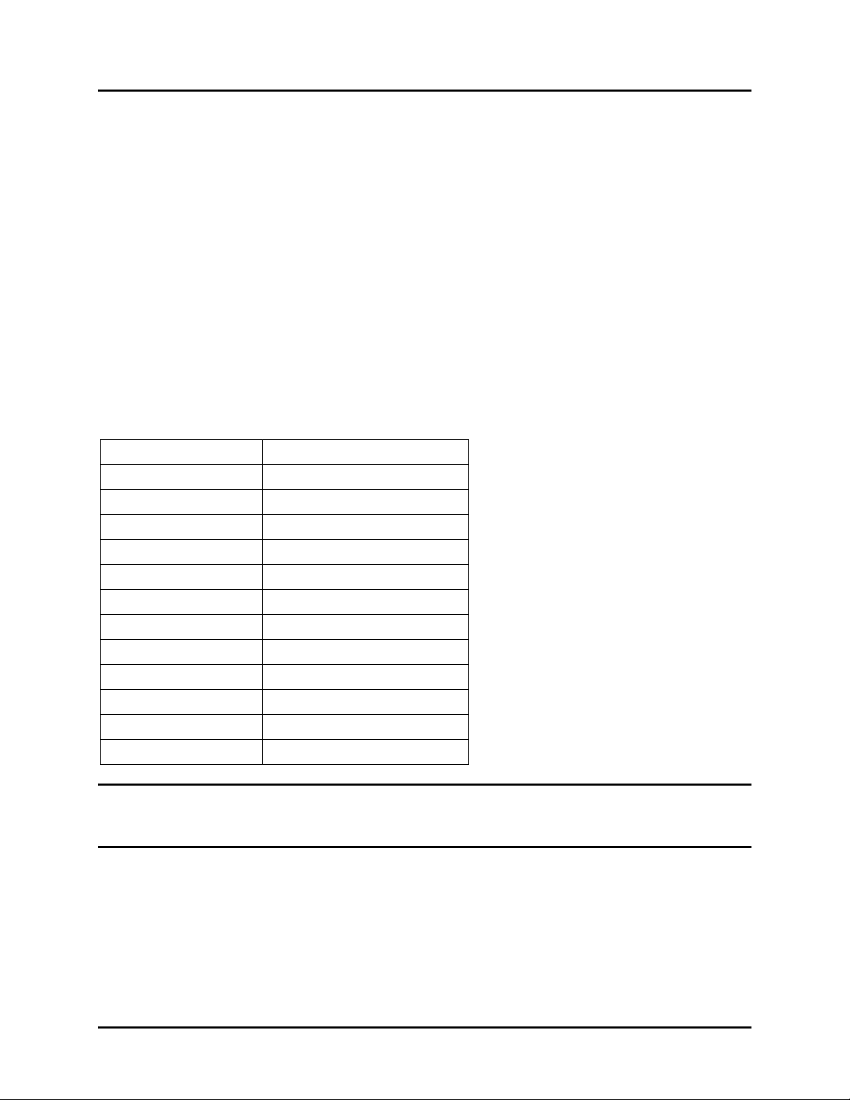
Inter-Shelf Communications Link (ISCL) Cabling
Standard straight-though 10/100BaseT Ethernet cabling is used to daisy-chain the
MTAS Inter-Shelf Communications Link (ISCL) between MTAS chassis. The COMM 1
RJ-45 connector of one shelf is connected to the COMM 2 RJ-45 connector of the next
shelf until the last shelf on the daisy chain has been connected as shown in Figure 31.
Shielded 8-wire CAT5 cable must be used for the ISCL installation. The COMM 1 and
COMM 2 RJ-45 jacks are shielded and tied to the chassis ground to accommodate
shielded RJ-45 plugs. On the last shelf in the daisy-chain, the ISCL bus terminator
(dongle) is inserted in COMM 1.
The ISCL cabling sequence for a full daisy-chained system (12 chassis) is listed in
Table 18.
Table 18: ISCL Cabling Sequence
Connect from: To:
Master COMM 1 Slave 1 COMM 2
Slave 1 COMM 1 Slave 2 COMM 2
Slave 2 COMM 1 Slave 3 COMM 2
Slave 3 COMM 1 Slave 4 COMM 2
Slave 4 COMM 1 Slave 5 COMM 2
Slave 5 COMM 1 Slave 6 COMM 2
Slave 6 COMM 1 Slave 7 COMM 2
Slave 7 COMM 1 Slave 8 COMM 2
Slave 8 COMM 1 Slave 9 COMM 2
Slave 9 COMM 1 Slave 10 COMM 2
Slave 10 COMM 1 Slave 11 COMM 2
Slave 11 COMM 1 ISCL Terminator Dongle
IMPORTANT: When using shielded cable, ensure devices on either end of the cable
have the same reference ground (earth / chassis / frame ground) in order to prevent
ground loops.
46
Installation Guide May 2008
Page 53
CT-IG-MTAS192-2008-v1_8.doc
Comtest Networks
MTAS-192
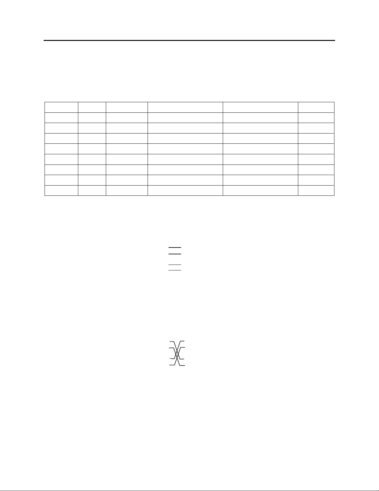
Ethernet Cabling
Connect to the Ethernet jack on the MTAS-CM control card using 10/100BaseT
Ethernet cable.
Table 19: RJ-45 10/100BaseT Connector Pinouts
Pin No. Name Description EIA/TIA 568A EIA/TIA 568B Ethernet
1 DSR/RI TX+ White/Green White/Orange
2 DCD TX- Green/White or Green Orange/White or Orange
3 DTR RX+ White/Orange White/Green
4 Blue/White or Blue Blue/White or Blue Not Used
5 White/Blue White/Blue Not Used
6 TD RX- Orange/White or Orange Green/White or Green
7 White/Brown White/Brown Not Used
8 Brown/White or Brown Brown/White or Brown Not Used
9
9
9
9
Straight-Through Cable Pinout
Connecting RJ-45 Ethernet Interface to a Hub or Router)
Router MTAS
3 TxD+
6 TxD-
1 RxD+
2 RxD-
3 TxD+
6 TxD-
1 RxD+
2 RxD-
Figure 37: Straight-Through Cable Pinouts
Crossover Cable Pinout
Connecting RJ-45 Ethernet interface to a PC)
PC MTAS
3 TxD+
6 TxD-
1 RxD+
2 RxD-
3 TxD+
6 TxD-
1 RxD+
2 RxD-
Figure 38: Crossover Cable Pinouts
June 2006 Installation Guide
47
Page 54
Comtest Networks
CT-IG-MTAS192-2008-v1_8.doc
MTAS-192
Serial Cabling
To communicate with the MTAS serially, use the AUX 1 RJ-45 jack located on the
Master (MTAS-CM) control card's front panel. Configure the terminal emulation
software for 9600 baud, with 8 data bits, 2 stop bits, no parity and no flow control. If the
connection is good, you should see a TL1>> prompt.
The pin layout for the RJ-45 serial port (AUX 1) follows the RS-232D standard.
Table 20: Pin Layout for RJ-45 (AUX 1) Serial Port using RS-232D Standard
Pin No. Name Notes/Description
1 DSR/RI Data Set Ready/Ring Indicator
2 DCD Data Carrier Detect
3 DTR Data Terminal Ready
4 SGND Signal Ground
5 RD Receive Data
6 TD Transmit Data
7 CTS Clear to Send
8 RTS Request to Send
NOTE: Only pins 4 (GND), 5 (RD), and 6 (TD) are used for this release.
Table 21: Pin Layout for Serial RJ-45 → DB-9 Adapter
MTAS Aux 1
pinout
4 → SGND
5 → RD
6 → TD
RJ-45 Female Colour DB-9 Female
RJ-45-F to DB-9-F Serial Adapter pinout
4 Red 5
5 Yellow 2
6 Green 3
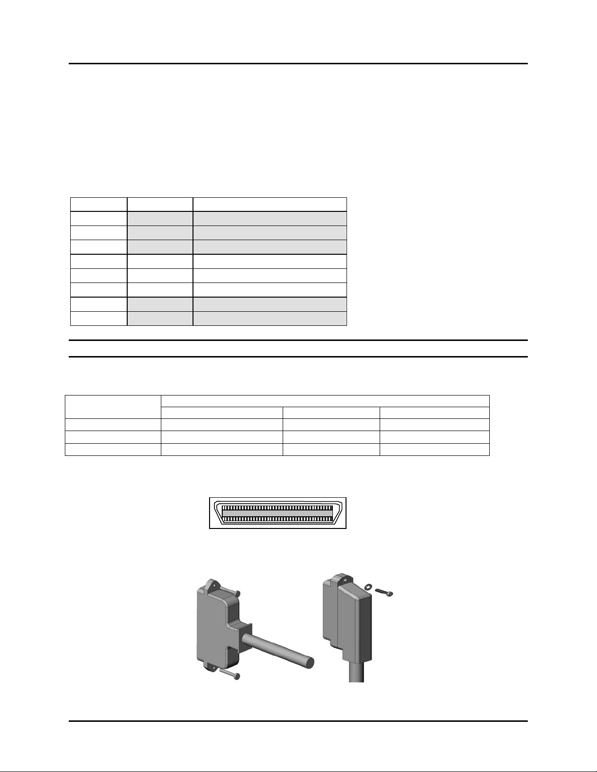
RJ-21 Cabling
Figure 39: RJ-21 Pinout Diagram
Pin 26
Pin 1
Figure 40: D-type and Right Angle (90 Degree) RJ-21 Connectors
48
Installation Guide May 2008
Page 55

CT-IG-MTAS192-2008-v1_8.doc
Table 22: RJ-21 Pinouts
Comtest Networks
MTAS-192
Port/Pair
Number
1 26 1 26 1 26 1
2 27 2 27 2 27 2
3 28 3 28 3 28 3
4 29 4 29 4 29 4
5 30 5 30 5 30 5
6 31 6 31 6 31 6
7 32 7 32 7 32 7
8 33 8 33 8 33 8
9 34 9 34 9 34
10 35 10 35 10 35
11 36 11 36 11 36
12 37 12 37 12 37
13 38 13 38 13 38
14 39 14 39 14 39
15 40 15 40 15 40
16 41 16 41 16 41
17 42 17 42 17 42
18 43 18 43 18 43
19 44 19 44 19 44
20 45 20 45 20 45
21 46 21 46 21 46
22 47 22 47 22 47
23 48 23 48 23 48
24 49 24 49 24
Alarm Cabling
DSL (Front) LINE/FACILITY (Rear) POTS/EQUIPMENT (Rear)
Tip Ring Tip Ring Tip Ring
9
10
11
12
13
14
15
16
17
18
19
20
21
22
23
49 24
Two female RJ11 jacks on the MTAS backplane correspond to MAJOR and MINOR
audible and visible alarms (normally open contacts).
Table 23: Alarm Cable Pinouts
MAJOR MINOR
Pin No. Alarm Pin No. Alarm
1 1
Major Visible Alarm
2
3 3
Major Audible Alarm
4
2
4
Minor Visible Alarm
Minor Audible Alarm
# # #
June 2006 Installation Guide
49
Page 56

Comtest Networks
MTAS-192
CT-IG-MTAS192-2008-v1_8.doc
50
Installation Guide May 2008
Page 57

CT-IG-MTAS192-2008-v1_8.doc
Comtest Networks
MTAS-192
Appendix B
Repair and Return
Services
If a shipment is damaged or if equipment is defective, contact Comtest Network's Repair
and Return Services department at +1 613 369-5499.
Specify the model number and serial number and provide a description of the problem.
You will be given an Return Material Authorization (RMA) number to include with your
shipment.
Ship the items as follows.
Attention: Repair & Return Services Department
Re: RMA # <your RMA number here>
Comtest Networks
171-E MacFarlane Road
Ottawa, Ontario
Canada
K2E 6V4
# # #
June 2006 Installation Guide
51
Page 58

Comtest Networks
MTAS-192
CT-IG-MTAS192-2008-v1_8.doc
52
Installation Guide May 2008
Page 59

CT-IG-MTAS192-2008-v1_8.doc
Comtest Networks
MTAS-192
Appendix C
Warranty
Comtest warrants all equipment and software manufactured by it and bearing its name
to be free from defects in workmanship and materials, during normal use and service,
for a period of one (1) year from the date of shipment. In the event that a defect in any
such equipment arises within the warranty period it shall be the responsibility of the
customer to return the equipment by prepaid transportation to a Comtest service centre
prior to the expiration of the warranty period for the purpose of allowing Comtest to
inspect and repair the equipment. If inspection by Comtest discloses a defect in
workmanship or material it shall, at its option, repair or replace the equipment without
cost to the customer, and thereafter return it to the customer by the least expensive
mode of transportation the cost of which shall be prepaid by Comtest. In no event shall
this warranty apply to equipment which has been modified without the written
authorization of Comtest, or which has been subject to abuse, neglect, accident, or
improper application. If inspection by Comtest discloses that the repairs that must be
made on the equipment are not covered by this warranty, the regular repair charges
shall apply to any repairs made to the equipment.
This warranty constitutes the only warranty applicable to the equipment sold by Comtest
and no other warranty or condition, statutory or otherwise, expressed or implied shall be
imposed upon Comtest nor shall any representation made by any person including a
representation by a representative or agent of Comtest be effective to extend the
warranty coverage provided herein. In no event (including, but not limited to the
negligence of Comtest, its agents, or employees) shall Comtest be liable for special or
consequential damages or damages arising from the loss of use of the equipment and
on the expiration of the warranty period all liability of Comtest whatsoever in connection
with the equipment shall terminate.
# # #
June 2006 Installation Guide
53
Page 60

Comtest Networks
MTAS-192
CT-IG-MTAS192-2008-v1_8.doc
54
Installation Guide May 2008
Page 61

CT-IG-MTAS192-2008-v1_8.doc
Appendix D
Acronyms and
Abbreviations
Table 24: Acronyms and Abbreviations
Comtest Networks
MTAS-192
Acronym/
Abbreviation
ACK Acknowledgement
ACO Alarm Cut-Off
AID Access IDentifier
ANSI American National Standards Institute
ASCII American Standard Code for Information Interchange
AUX Auxiliary
AWG American Wire Gauge
CAT Category
CD Compact Disk
CM Control Module
CO Central Office
CPE Customer Premises Equipment
CPT Circuit Pack Type
CTAG Correlation TAG
DC Direct Current (voltage)
DNS Domain Name Server/Service
DSL Digital Subscriber Loop
DSLAM Digital Subscriber Loop Access Multiplexer
ETSI European Telecommunications Standards Institute
IP Internet Protocol
ISCL Inter-shelf Communications Link
LAN Local Access Network
lbs pounds
LED Light Emitting Diode
MAC Media Access Control (address)
MDF Main Distribution Frame
MTAS Metallic Test Access System
Meaning
June 2006 Installation Guide
55
Page 62

Comtest Networks
MTAS-192
CT-IG-MTAS192-2008-v1_8.doc
Acronym/
Abbreviation
MTAU Metallic Test Access Unit
NEBS Network Equipment Building System
NO Normally Open
OSS Operational Support System
POTS Plain Old Telephone Service
PSTN Public Switched Telephone Network
RU Rack Unit
SID Site IDentifier
STP Shielded Twisted Pair
TAP Test Access Path
TIA Telecommunications Industry Association
TID Target IDentifier
TL1 Transaction Language 1
UID User Identification
UTP Unshielded Twisted Pair
Meaning
# # #
56
Installation Guide May 2008
Page 63

CT-IG-MTAS192-2008-v1_8.doc
Comtest Networks
MTAS-192
Appendix E
Recommended
Cabling Practices
E.1. Introduction
This appendix includes recommended cabling practices that should be followed in order
to avoid potential hazards and to achieve proper operation of your MTAS -192 Metallic
Test Access System.
E.2. General Cabling Rules
1. Avoid running cables parallel to power cables.
2. Do not bend cables to less than four times the diameter of the cable.
3. When bundling groups of cables together (using cable ties, zip ties, etc.), snug
the cables together firmly, but do not over-cinch them or deform the cables.
4. Keep cables away from devices which can introduce electrical noise (e.g., copy
machines, electric heaters, speakers, printers, televisions, fluorescent lights,
welding machines, microwave ovens, telephones, fans, elevator motors, electric
ovens, dryers, washing machines, shop equipment, etc.).
5. Avoid stretching unshielded twisted pair (UTP) cables. If this is unavoidable, the
strain (force) on the cable must not exceed 25 lbs.
6. Never run UTP cable to the outside of a building. This presents a very
dangerous lightning hazard.
7. Never use a stapler to secure UTP cables. Instead, use telephone wire hangers
(which are available at most hardware stores).
8. Avoid reusing old cables.
E.3. CAT5 Cable Types: Stranded vs. Solid
Most patch cables have stranded wire. Stranded wire is normally specified for use in
patch cables due to its superior flexibility. There are debates (in the technical sector of
the structured wiring community) regarding the possible use of solid conductors for
patch cables because it is supposedly more stable under a variety of conditions.
NOTE: Comtest offers custom solid copper category 5E patch cables in Plenum
insulation in lengths of up to 295 feet. These cables are suitable for use in air handling
(Plenum) ceilings and environments.
June 2006 Installation Guide
57
Page 64
Comtest Networks
CT-IG-MTAS192-2008-v1_8.doc
MTAS-192
Solid category 5 (or CAT5) cable is recommended for:
• all horizontal runs
• runs between wiring closets
• runs over 25 feet
• runs less than 328 feet or 100 meters (the maximum recommended length)
• applications in which the cable is not flexed.
Stranded category 5 (or CAT5) cable is recommended for:
• applications that may involve repeated flexing of the cable (stranded cable is built
to withstand repeated flexing without damage to inner conductors)
• PC-to-wallplate applications
• short runs of 25 feet or less (due to the higher attenuation associated with
stranded cabling).
NOTE: In addition to choosing between stranded and solid CAT5 cabling, be sure to
determine whether plenum-rated or non-plenum-rated cable is required for your
particular application. Plenum-rated cable has a special outer jacket and is generally
required in all air returns, dropped ceilings, and public buildings. As fire codes vary
from area to area, be sure to check with your local Fire Marshall.
E.4. Common Causes of Cable Failure
Table 25 shows a list of cabling mistakes that are often the cause of cable failures.
Table 25: Common Causes of Cable Failure
Problem Solution
Modular plugs are not
terminated properly
Pair-twists are not
maintained
• Use the right type of plug (stranded vs. solid conductor).
• Follow the appropriate color code.
• Add an additional twist to the pair (if needed) when
terminating the modular jack to ensure that the cutter on
the termination tool is facing the right direction.
Too much cable
jacketing is removed
Poor cable routing
• Keep the cable jacket intact up to the connector.
• Remove only enough of the jacket to terminate the pairs.
• Keep cables separate from power and other
telecommunications cabling.
• Do not exceed 25 lbs of tension on cables being pulled.
• Avoid cable twisting.
• Avoid friction and “rubs” between the cable and other
items (e.g., nails, screws, and even poorly drilled joists
and studs).
58
Installation Guide May 2008
Page 65

CT-IG-MTAS192-2008-v1_8.doc
Problem Solution
Comtest Networks
MTAS-192
Poor documentation
• Keep good records of all cables placed in the job
including all test data.
• Leave a copy of cabling documentation with the owner
and in the distribution center.
E.5. RJ45 Plug Types
CAT5 cables are typically terminated with RJ-45 connectors. Creating usable and longlasting patch cables requires more than just the appropriate cable. The appropriate
RJ45 plug types must also be used. There are a variety of RJ45 plug types available.
Be sure to choose the plug type that is appropriate for your particular application.
Consider the following when choosing RJ45 plugs.
• Choose RJ45 plugs that are specifically made for CAT5 round cable (not the
less-expensive Telco ones for flat satin cable). The ones rated for CAT5 (and
CAT6) have a thicker gold plating.
• Choose RJ45 plugs that are appropriate for your wire type (i.e., solid vs.
stranded). The aligned tine version is intended for use with stranded cable. The
bent tine version, although intended for use with solid core cable, may also be
used with stranded.
• Choose RJ45 plugs that are compatible with your RJ45 crimp tools. There may
be subtle differences between RJ45 plugs and tools of different manufacturers.
• Consider the pros and cons of using “no-fail” RJ45 plugs (the wires exit the end
of the plug, you crimp, then trim off the excess for a “no fail” connection).
Although they may provide a “no fail” connection, (1) they are more expensive,
(2) they leave the copper conductors exposed at the end, (3) they are not the
best for outdoor use, and (4) they are not ideal for patch cable use where the
plugs are not protected by the jack.
E.6. 568A vs. 568B Wiring Standards
For patch cables, 568B wiring is by far, the most common wiring method. Virtually all
pre-assembled patch cables are wired to the B standard. There is no difference in
connectivity between 568B and 568A cables. Therefore, a 568B patch cable should
work fine on a 568A cabling system, and visa-versa.
NOTE: Comtest offers custom CAT5E and CAT6 cables in both 568A and 568B wiring
schemes.
For both wiring standards, the pins of an RJ45 jack are numbered 1-8.
• Pin 1 is on the right when looking at the face of the jack.
• Pin 8 is on the left when looking at the face of the jack.
• Pin 1 is on the left when looking at the face of the plug.
• Pin 8 is on the right when looking at the face of the plug.
June 2006 Installation Guide
59
Page 66
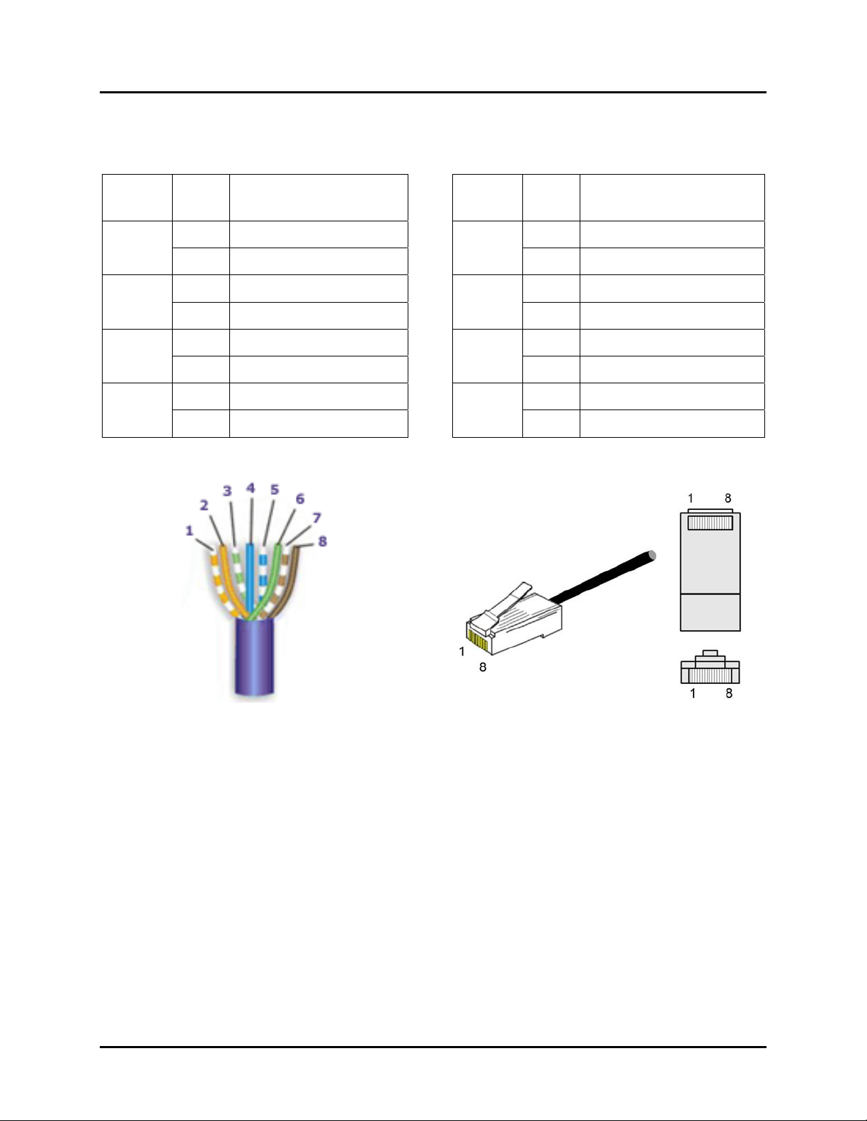
Comtest Networks
CT-IG-MTAS192-2008-v1_8.doc
MTAS-192
Pinouts and wire colors are summarized in Table 26.
Table 26: RJ45 Wiring by 568A and 568B Standards
568B
Pair #
1
2
3
4
Pin Wire Colors (568B)
568A
Pair #
Pin Wire Colors (568B)
5 White/Blue 5 White/Blue
1
4 Blue/White
4 Blue/White
1 White/Orange 3 White/Green
2
2 Orange/White
6 Green/White
3 White/Green 1 White/Orange
3
6 Green/White
2 Orange/White
7 White/Brown 7 White/Brown
4
8 Brown/White
8 Brown/White
Figure 41: Cable with 568B Wire Assignments
Figure 42: RJ45 Plug Showing Pin Numbers
60
Installation Guide May 2008
Page 67

CT-IG-MTAS192-2008-v1_8.doc
Comtest Networks
MTAS-192
E.7. Crimping Shielded RJ-45 Plugs onto 8-Wire STP CAT5 Cable
Step Description
1 Preparation: Assemble appropriate materials:
• length of shielded twisted pair (STP) CAT5 cable
• CAT5 plug
• wire cutters/strippers
• crimping tool
• Multimeter/continuity tester
2 Strip: At one end of the CAT5 cable, carefully remove approximately one
inch of the cable jacket, exposing the foil shield.
3 Foil: Carefully pull back the foil shield onto the remaining cable jacket,
exposing the unshielded drain wire and the eight individually shielded wires.
4 Drain Wire: Select the unshielded drain wire and wrap it around the foil
shield.
5
Separate: Untwist a portion of each pair of wires (to approximately 1/8″
from the jacket).
6 Arrange: Arrange the individual wires according to the associated TAP or
DATA connection specifications (refer to Appendix A). Be sure to flatten the
individual conductors to facilitate their insertion into the RJ45 plug.
7 Trim: Using the wire cutters, trim perpendicularly across the eight
conductors, ensuring that each conductor is of equal length. Be sure to
leave enough of the conductors for insertion into the RJ45 plug
(approximately 1/2″).
8
Insert: Insert the wires (and about 1/4″ of the cable jacket, for strain relief)
into the CAT 5 plug. Ensure that the orientation is correct between each tine
of the plug and each wire in the CAT5 cable.
9 Crimp: Using the crimping tool, secure the RJ45 plug to the CAT5 cable.
10 Repeat: Repeat the process for the other end of the cable, if needed.
11 Test: Using a multimeter or continuity tester, verify that each line of the
cable is connected and operating properly.
June 2006 Installation Guide
61
Page 68
Comtest Networks
MTAS-192
E.8. Crimping Unshielded RJ-45 Plugs onto 8-Wire UTP CAT5 Cable
Step Description
1 Preparation: Assemble appropriate materials:
2 Strip: At one end of the CAT5 cable, carefully remove approximately one
inch of the cable jacket, exposing the eight individually shielded wires.
3
4 Arrange: Arrange the individual wires according to the associated TAP or
5 Trim: Using the wire cutters, trim perpendicularly across the eight
6
7 Crimp: Using the crimping tool, secure the RJ45 plug to the CAT5 cable.
8 Repeat: Repeat the process for the other end of the cable, if needed.
9 Test: Using a multimeter or continuity tester, verify that each line of the
Separate: Untwist a portion of each pair of wires (to approximately 1/8″
from the jacket).
DATA connection specifications (refer to Appendix A). Be sure to flatten the
individual conductors to facilitate their insertion into the RJ45 plug.
conductors, ensuring that each conductor is of equal length. Be sure to
leave enough of the conductors for insertion into the RJ45 plug
(approximately 1/2″).
Insert: Insert the wires (and about 1/4″ of the cable jacket, for strain relief)
into the CAT 5 plug. Ensure that the orientation is correct between each tine
of the plug and each wire in the CAT5 cable.
cable is connected and operating properly.
CT-IG-MTAS192-2008-v1_8.doc
• length of unshielded twisted pair (UTP) CAT5 cable
• CAT5 plug
• wire cutters/strippers
• crimping tool
• Multimeter/continuity tester
# # #
62
Installation Guide May 2008
Page 69

CT-IG-MTAS192-2008-v1_8.doc
Index
bridged ............................................................................... 2
1
10/100BaseT......................................................... 42, 46, 47
19" racks...........................................................................17
2
23" racks.....................................................................14, 17
25 pair ....................................................... 1, 7, 9, 21, 25, 42
2-wire........................................................................3, 5, 41
2-wire circuits.....................................................................3
4
4-wire..............................................................................3, 5
4-Wire.................................................................................9
4-wire circuits.....................................................................3
5
50 pin..............................................................................1, 9
A
Abbreviations....................................................................55
ACO..............................................................................8, 55
Acronyms .........................................................................55
Activation...............................................................6, 14, 33
Activation and Testing phase............................................14
address........................................................................51, 55
unique..........................................................................19
ADSL Splitter...............................................................1, 25
AE9, 10, 45
AF 9, 10, 45
alarm block.......................................................................32
Alarm Contacts.............................................................7, 22
Alarm Cut-off...............................................................8, 55
alarms .......................................................................7, 8, 22
cable pinouts................................................................49
Angle Shroud kits.............................................................15
anti-static mat ...................................................................17
applications.....................................................................1, 8
AUX 1 .................................................. 8, 24, 30, 36, 42, 48
B
backplane.................................. 1, 15, 27, 28, 30, 31, 42, 49
baud ................................................................24, 30, 36, 48
Binary ID................................................................8, 19, 43
bolts..................................................................................13
breakers.............................................................................14
Bridged Monitor............................................................... 10
broadband........................................................................... 1
Bus Extender.............................................................. 31, 44
cable pair..........................................................................10
cable tie mounts................................................................16
cabling.......................................................15, 21, 33, 46, 48
Cabling......................................6, 28, 44, 45, 46, 47, 48, 49
custom......................................................................... 44
card ejector.................................................................17, 19
Card Slot Assignments.......................................................5
card slots .................................................................. 3, 7, 21
CAT3/5 ......................................................................28, 29
CAT5.......................................................................... 15, 31
central office .................................................................... 13
circuit boards...................................................................18
circuit packs......................................................... 15, 33, 41
COM 1 ............................................................. 8, 24, 30, 42
COMM 1...............................................7, 21, 30, 31, 32, 46
COMM 2.................................................... 7, 21, 30, 31, 46
COMM1 ........................................................................... 32
Connecting to DSL........................................................... 29
connectors ...........................................14, 16, 21, 24, 27, 30
control card .....................................4, 19, 24, 30, 36, 47, 48
Control Card............................................... 3, 19, 24, 30, 43
control modules.................................................................. 1
Controller Card...........................................................3, 5, 8
cooling..............................................................................15
CRAFT......................................................................... 8, 24
daisy chain........................................................ 7, 21, 43, 46
daisy-chain........................................................... 19, 30, 31
daisy-chained ..................................................... 1, 8, 30, 41
Daisy-chaining................................................................. 30
dangerous voltage levels.................................................. 26
data bits.......................................................... 24, 30, 36, 48
DATA1 ................................................................ 30, 31, 44
DB-9 connector................................................ 8, 24, 30, 42
debug port .............................................................. 8, 24, 30
dimensions ......................................................................... 3
DIP Switch Settings ......................................................... 43
DIP switches .................................................................... 19
DNS..................................................................................55
dongle................................................................... 15, 16, 32
downstream.................................................................... 1, 9
dry contacts.................................................................. 7, 22
DSL interface..................................................................... 1
DSL splitter........................................................................1
Comtest Networks
MTAS-192
C
D
June 2006 Installation Guide
63
Page 70

Comtest Networks
MTAS-192
CT-IG-MTAS192-2008-v1_8.doc
DSLAM................................................ 1, 25, 29, 41, 45, 55
Dual Wire Terminal Header................................................7
E
ear mounts.........................................................................15
EMI (Electro-magnetic Interference) suppressor..............15
EMI suppressor...........................................................15, 27
enclosures.........................................................................13
Equipment...............................................................9, 55, 56
equipment damage............................................................26
equipment rack ..................................... 3, 13, 14, 15, 17, 32
ESD handling precautions.................................................15
ESD precautions...............................................................17
Ethernet..................... 2, 8, 14, 24, 30, 31, 36, 37, 42, 46, 47
ETSI..........................................................3, 4, 5, 16, 41, 55
EU-5807 .........................................................3, 4, 5, 16, 41
F
faceplate..............................................17, 19, 29, 30, 42, 43
faceplates..........................................................................33
Facility................................................................................9
flanges.....................................................................3, 15, 17
flow control.....................................................24, 30, 36, 48
four-wire TAP.....................................................................2
four-wire Test Access Paths................................................2
fuse ...................................................................................33
fuses............................................................................14, 33
fusing................................................................................13
G
gateway.............................................................................14
GR-818...............................................................................1
GR-834.........................................................................1, 42
ground wire.......................................................................26
grounding....................................................................17, 26
Grounding Connector .......................................................26
ISCL..........................................7, 15, 21, 30, 31, 32, 46, 55
bus length max............................................................ 32
ISCL Bus...................................................................... 7, 21
ISCL bus terminator.........................................................15
L
LAN performance............................................................. 36
LED.................................................................... 6, 8, 33, 55
LEDs...................................................................... 8, 33, 43
binary ID..................................................................... 19
line card.......................1, 4, 7, 10, 15, 21, 25, 29, 33, 41, 42
line monitoring...................................................................1
Line/Downstream............................................. 7, 21, 28, 49
Local Area Network ......................................................... 36
local loop............................................................................ 1
logical ID ......................................................................... 19
look-in................................................................................ 2
look-out.............................................................................. 2
Loop-around..................................................................... 10
Loop-around Mode........................................................... 11
M
master........................................8, 14, 24, 30, 31, 33, 36, 43
Master .....................................3, 5, 8, 16, 24, 31, 33, 44, 48
metallic test access............................................................. 3
model number .................................................................. 51
Modes.............................................................................. 10
monitor...........................................................................1, 2
mounting flanges.................................................... 3, 14, 17
universal...................................................................... 17
MT-501 ................................................................ 3, 4, 5, 16
MT-502 ................................................................ 3, 4, 5, 16
MT-5807 .............................................................. 3, 4, 5, 16
MT-5820 ........................................................ 3, 4, 5, 16, 41
MT-5820V ..................................................................... 3, 5
MT-5821 .............................................................. 3, 4, 5, 16
MTAS-CM..............3, 4, 5, 8, 16, 19, 24, 30, 36, 43, 47, 48
MTAS-CS .................................3, 4, 5, 8, 16, 19, 24, 30, 43
H
N
Hardware Overview............................................................3
Hex Nut kits......................................................................15
hex nuts.............................................................................16
High-impedance Monitor..................................................10
High-Impedance Monitor Mode.......................................11
hitless connection..............................................................10
Hyperterminal...................................................................36
I
Inspection .........................................................................15
installation ........................................................................13
installers............................................................................13
Installing the MTAS Shelf................................................17
Inter-shelf Communications Link (ISCL) Bus Extender...31
intrusive test access.............................................................1
IP addresses
dummy.........................................................................37
IP settings.........................................................................36
64
Installation Guide May 2008
NA-5820 ........................................................ 3, 4, 5, 16, 41
non-splitter.........................................................................1
normally open .................................................................. 49
North American.............................................. 3, 4, 5, 16, 41
O
Operational Support System.........................................1, 56
OSS........................................................................ 1, 13, 56
P
packing list....................................................................... 15
parity.............................................................. 24, 30, 36, 48
ports.................................................................. 7, 21, 32, 41
per configuration........................................................... 1
POTS/Upstream............................................... 7, 21, 28, 49
POTS/Upstream Pairs .................................................. 7, 21
Page 71

CT-IG-MTAS192-2008-v1_8.doc
Comtest Networks
MTAS-192
power.............................................. 7, 13, 14, 22, 26, 27, 33
Power .................................................. 14, 15, 26, 27, 33, 42
Power Distribution Block ................................................. 33
power distribution panel ...................................................13
power feed ..................................................................14, 27
power feed redundancy.....................................................14
power feeds.............................................................7, 22, 27
power source connections.................................................26
ProCOMM Plus................................................................36
R
rack location .....................................................................13
redundant power ...............................................................33
Remote Digital Access Centers (RDACs)........................13
remote test access ...............................................................1
Repair and Return Services department............................51
Return Material Authorization (RMA).............................51
return procedure................................................................15
RJ-11.......................................................................7, 22, 32
RJ-21................................. 1, 7, 9, 15, 21, 25, 28, 29, 42, 48
pinouts.........................................................................49
RJ-21 connector..........................................1, 25, 28, 29, 42
RJ-21 connectors ..........................................................1, 28
RJ-45................... 7, 8, 15, 21, 24, 30, 31, 36, 42, 46, 47, 48
RS-232............................................................................2, 8
serial port.......................................................................2
S
screwdriver .......................................................................13
screws...................................................................15, 17, 19
non-standard................................................................17
over-torquing...............................................................17
serial cable........................................................................36
serial communication..................................................24, 30
serial number ....................................................................51
shelf position.....................................................................13
Shelf Power.............................................................7, 14, 22
shielded...................................................................7, 21, 31
site survey.........................................................................13
slave...................................................... 8, 19, 24, 30, 31, 43
Slave....................................... 3, 5, 8, 16, 19, 24, 31, 33, 44
Specifications......................................33, 41, 57, 59, 61, 62
Split ..................................................................................10
Split Mode........................................................................12
splitter.............................................................1, 7, 9, 10, 21
Splitter Card..................................................................3, 16
modes ..........................................................................10
Splitter Cards..................................................................4, 5
static bags.........................................................................15
static IP address................................................................14
stop bits...........................................................24, 30, 36, 48
subnetwork........................................................................14
subnetwork mask..............................................................14
subscriber lines...................................................................1
switch settings ...................................................... 19, 30, 43
inspecting.................................................................... 19
system administrator........................................................ 37
T
TAL...................................................................... 30, 31, 44
pinouts.........................................................................45
TAL Bus..................................................................... 31, 44
pinouts.........................................................................45
TAP bus ...........................................................................10
TAPs .............................................2, 8, 9, 10, 30, 31, 33, 44
TAU ............................................................................. 7, 21
TCP/IP connection...........................................................24
telnet........................................................................... 24, 30
temperature range............................................................. 13
terminal header................................................................. 27
Terminal Header.................................................................7
terminator.........................................................................16
test access................................................................. 1, 3, 41
Test Access 1, 2, 3, 4, 5, 8, 9, 15, 16, 25, 30, 31, 41, 44, 45,
55, 56
test access applications....................................................... 1
Test Access Paths......................................................... 9, 30
test access shelf.................................................................. 1
test head ........................................................... 1, 13, 30, 31
test mode............................................................................ 9
Testing.............................................................. 6, 12, 14, 33
Testing in Both Directions ............................................... 12
tie wrap.............................................................................28
tie wraps..................................................................... 13, 16
TL1............................................2, 10, 12, 24, 37, 42, 48, 56
Transaction Language 1...............................................2, 56
Transparent/ Isolated ........................................................ 10
Transparent/Isolation Mode ............................................. 10
troubleshooting................................................................... 1
two-wire circuits.................................................................1
U
upstream......................................................................... 1, 9
V
vertical rack space............................................................ 15
voice and data services....................................................... 1
VT emulation software..................................................... 36
VT terminal Setup Directory............................................ 36
W
warnings............................................................................. 2
warranty ........................................................................... 53
washers....................................................................... 15, 17
wrist strap .................................................................. 15, 17
# # #
June 2006 Installation Guide
65
Page 72

Comtest Networks
MTAS-192
CT-IG-MTAS192-2008-v1_8.doc
66
Installation Guide May 2008
 Loading...