

Page 1

SFC4200/SFC1275G
Synthesized Frequency
Downconverter
Installation and Operation Manual
TM054 - Rev. 4.0
March, 2002
- NOTICE -
2002, Radyne ComStream Corporation. This
manual may not in whole or in part be copied,
reproduced, translated or reduced to any
electronic or magnetic storage medium without
the written consent of a duly authorized officer
of Radyne ComStream Corporation.
Radyne ComStream Corporation •• 3138 E. Elwood St. •• Phoenix, AZ 85034 •• (602) 437-9620 •• Fax: (602) 437-4811
Page 2

Page 3

Latest Software Revision Confirmation
When new features are added to Radyne ComStream Corporation
equipment, the control parameters are appended to the end of the
Non-Volatile Section of the Remote Communications Specification,
and status of the features, if any, are added at the end of the Volatile
Section. If a remote M&C queries two pieces of Radyne ComStream
Corporation equipment with different revision software, they could
respond with two different sized packets. The remote M&C MUST
make use of the non-volatile count value to index to the start of the
Volatile Section. If the remote M&C is not aware of the newly added
features to the product, it should disregard the parameters at the end
of the Non-Volatile Section and index to the start of the Volatile
Section.
Before creating any software based on the information contained in
this document, contact the Radyne ComStream Corporation Customer
Service Department (602-437-9620) to find out if the software revision
for that piece of equipment is current and that no new features have
been added since the release of this document.
Page 4

Warranty Policy DM240 Synthesized Frequency Downconverter
2
Page 5

SFC4200/SFC1275G Synthesized Frequency Downconverter Warranty Policy
Radyne ComStream Corporation Warranty Policy
Warranty and Service
Radyne ComStream Corporation (Seller) warrants the items manufactured and sold by Radyne
ComStream Corporation to be free of defects in material and workmanship for a period of two (2) years
from date of shipment Radyne ComStream Corporation's obligation under its warranty is limited in
accordance with the periods of time and all other conditions stated in all provisions of this warranty.
This warranty applies only to defects in material and workmanship in products manufactured by Radyne
ComStream Corporation. Radyne ComStream Corporation makes no warranty whatsoever concerning
products or accessories not of its manufacture. Repair, or at Radyne ComStream Corporation's option,
replacement of the Radyne ComStream Corporation products or defective parts therein shall be the sole
and exclusive remedy for all valid warranty claims.
Warranty Period
The applicable warranty period shall commence on the date of shipment from Radyne ComStream
Corporation's facility to the original purchaser and extend for the stated period following the date of
shipment. Upon beginning of the applicable Radyne ComStream Corporation warranty period, all
customer's remedies shall be governed by the terms stated or referenced in this warranty. In-warranty
repaired or replacement products or parts are warranted only for the remaining unexpired portion of the
original warranty period applicable to the repaired or replaced products or parts. Repair or replacement of
products or parts under warranty does not extend the original warranty period.
Warranty Coverage Limitations
The following are expressly not covered under warranty:
1. Any loss, damage and/or malfunction relating in any way to shipping, storage, accident, abuse,
alteration, misuse, neglect, failure to use products under normal operating conditions, failure to
use products according to any operating instructions provided by Radyne ComStream
Corporation, lack of routine care and maintenance as indicated in any operating maintenance
instructions, or failure to use or take any proper precautions under the circumstances.
2. Products, items, parts, accessories, subassemblies, or components which are expendable in
normal use or are of limited life, such as but not limited to, bulbs, fuses, lamps, glassware, etc.
Radyne ComStream Corporation reserves the right to revise the foregoing list of what is covered
under this warranty.
Warranty Replacement and Adjustment
Radyne ComStream Corporation will not make warranty adjustments for failures of products or parts which
occur after the specified maximum adjustment period. Unless otherwise agreed, failure shall be deemed to
have occurred no more than seven (7) working days before the first date on which a notice of failure is
received by Radyne ComStream Corporation. Under no circumstances shall any warranty exceed the
period stated above unless expressly agreed to in writing by Radyne ComStream Corporation.
Liability Limitations
This warranty is expressly in lieu of and excludes all other express and implied warranties, Including but
not limited to warranties of merchantability and of fitness for particular purpose, use, or applications, and
all other obligations or liabilities on the part of Radyne ComStream Corporation, unless such other
warranties, obligations, or liabilities are expressly agreed to in writing by Radyne ComStream Corporation.
All obligations of Radyne ComStream Corporation under this warranty shall cease in the event its products
or parts thereof have been subjected to accident, abuse, alteration, misuse or neglect, or which have not
been operated and maintained in accordance with proper operating instructions.
TM054 – Rev. 4.0 iii
Page 6

Warranty Policy SFC4200/SFC1275G Synthesized Frequency Downconverter
In no event shall Radyne ComStream Corporation be liable for Incidental, consequential, special or
resulting loss or damage of any kind howsoever caused. Radyne ComStream Corporation’s liability for
damages shall not exceed the payment, if any, received by Radyne ComStream Corporation for the unit or
product or service furnished or to be furnished, as the case may be, which is the subject of claim or
dispute.
Statements made by any person, including representatives of Radyne ComStream Corporation, which are
inconsistent or in conflict with the terms of this warranty, shall not be binding upon Radyne ComStream
Corporation unless reduced to writing and approved by an officer of Radyne ComStream Corporation.
Warranty Repair Return Procedure
Before a warranty repair can be accomplished, a Repair Authorization must be received. It is at this time
that Radyne ComStream Corporation will authorize the product or part to be returned to the Radyne
ComStream Corporation facility or if field repair will be accomplished. The Repair Authorization may be
requested in writing or by calling:
Radyne ComStream Corporation
3138 E. Elwood St.
Phoenix, Arizona 85034 (USA)
ATTN: Customer Support
Phone: (602) 437-9620 Fax: (602) 437-4811
Any product returned to Radyne ComStream Corporation for examination must be sent prepaid via the
means of transportation indicated as acceptable to Radyne ComStream Corporation. Return Authorization
Number must be clearly marked on the shipping label. Returned products or parts should be carefully
packaged in the original container, if possible, and unless otherwise indicated, shipped to the above
address.
Non-Warranty Repair
When a product is returned for any reason, Customer and its shipping agency shall be responsible for all
damage resulting from improper packing and handling, and for loss in transit, not withstanding any defect
or nonconformity in the product. By returning a product, the owner grants Radyne ComStream
Corporation permission to open and disassemble the product as required for evaluation. In all cases,
Radyne ComStream Corporation has sole responsibility for determining the cause and nature of failure,
and Radyne ComStream Corporation's determination with regard thereto shall be final.
iv TM054 - Rev. 4.0
Page 7
SFC4200/SFC1275G Synthesized Frequency Downconverter Record of Revisions
SFC4200/SFC1275G Synthesized Frequency Downconverter
Installation and Operation Manual
TM054 – Record of Revisions
Radyne ComStream Corporation is constantly improving its products and therefore the
information in this document is subject to change without prior notice. Radyne ComStream
Corporation makes no warranty of any kind with regard to this material, Including but not limited
to the implied warranties of merchantability and fitness for a particular purpose. No responsibility
for any errors or omissions that may pertain to the material herein is assumed. Radyne
ComStream Corporation makes no commitment to update nor to keep current the information
contained in this document. Radyne ComStream Corporation assumes no responsibility for use
of any circuitry other than the circuitry employed in Radyne ComStream Corporation systems
and equipment.
Revision
Level
1.0 7-15-96 Initial Release
2.0 12-01-96 Added interconnection diagram, redefined connector pinouts, updated serial
2.1 12-16-96 Updated Operation Section, updated Serial Protocol and added additional
3.0 2-03-97 Updated Operation Section, added 1:1 and 1:8 Serial Protocol data.
3.1 4-24-97 Added Extended Band data, additional 1:8 operation data and backup 1:8
4.0 3-4-02 Merged with Rev. 4.0, TM062, SFC1275G Global Ku-Band Synthesized
Date Reason for Change
protocol, enhanced operation section, added remote serial I/O operation.
figures to Appendix C.
flow chart
Frequency Downconverter.
TM054 - Rev. 4.0 v
Page 8

SFC4200/SFC1275G Synthesized Frequency Downconverter
This Page is Intentionally Left Blank
vi TM054 - Rev. 4.0
Page 9

SFC4200/SFC1275G Synthesized Frequency Downconverter Table of Contents
Table of Contents
Section 1 - Introduction
1.0 Description______________________________________________________1-1
1.1 Protection Switch Versatility_________________________________________ 1-2
Section 2 - Installation
2.0 Installation Requirements __________________________________________ 2-1
2.1 Unpacking ______________________________________________________ 2-1
2.2 Removal and Assembly____________________________________________2-1
2.3 Mounting Considerations___________________________________________2-1
2.4 Initial Power-Up __________________________________________________2-1
2.5 SFC Downconverter Interconnections _________________________________ 2-2
Section 3 - Operation
3.0 Theory of Operation_______________________________________________3-1
3.1 Signal RF Assembly ______________________________________________3-1
3.1.1 AS/4010 Converter First Mixer C-Band Downconverter (SFC4200) _________ 3-2
3.1.2 AS/4011 Converter Second Mixer C-Band Downconverter (SFC4200) ______ 3-2
3.1.3 AS/4007 Converter First Mixer Ku-Band Downconverter (SFC1275G)_______3-3
3.1.4 AS/4012 Converter Second Mixer Ku-Band Downconverter (SFC1275G) ____3-3
3.2 AS/3048 M&C Controller Assembly___________________________________3-4
3.3 Synthesizer Modules ______________________________________________3-4
3.3.1 Synthesizer Module (SFC4200) ____________________________________3-5
3.3.2 Synthesizer Module (SFC1275G)___________________________________3-5
3.4 AS/3072 Frequency Reference Assembly______________________________ 3-7
3.5 AS/3228 Power Supply System______________________________________3-7
3.5.1 AS/3228 Output Board ___________________________________________3-7
3.6 Frequency Accuracy ______________________________________________ 3-8
3.7 Amplitude Accuracy_______________________________________________3-8
TM054 - Rev. 4.0 vii
Page 10

Table of Contents SFC4200/SFC1275G Synthesized Frequency Downconverter
Section 4 – User Interfaces
4.0 User Interfaces __________________________________________________ 4-1
4.1 Front Panel User Interface__________________________________________4-1
4.1.1 Front Panel LED Indicators________________________________________4-1
4.1.2 Front Panel LCD Display _________________________________________ 4-2
4.1.3 Front Panel Keypad _____________________________________________4-4
4.1.3.1 Soft Reset ___________________________________________________4-4
4.1.4 Monitoring Ports ________________________________________________ 4-4
4.2 Menu Screens ___________________________________________________4-4
4.2.1 Root Menu ____________________________________________________4-8
4.2.1.1 Status ______________________________________________________ 4-9
4.2.1.2 Set/Change Status ___________________________________________4-10
4.2.1.3 Frequency __________________________________________________ 4-10
4.2.1.4 Gain_______________________________________________________ 4-11
4.2.2 Converter Type Menu___________________________________________4-11
4.2.3 Switch Fault Menu _____________________________________________4-11
4.2.4 Converter Faults Menu __________________________________________ 4-12
4.2.5 Utility Access Menus____________________________________________4-13
4.2.6 Switch Configuration Menu_______________________________________4-14
4.2.7 Learn Menu (Backup Converter Only) ______________________________ 4-14
4.2.8 Learn Status Menus (Backup Converter Only) ________________________4-14
4.2.9 Configuration Menu ____________________________________________ 4-15
4.2.10 Reference Menu______________________________________________4-16
4.2.10.1 Reference Offset____________________________________________4-17
4.2.10.2 Reference Stability __________________________________________4-17
4.2.11 Output Attenuator Calibration Menu _______________________________ 4-18
4.3 Serial Protocol __________________________________________________ 4-19
4.4 Command Structure______________________________________________4-19
4.5 Control Commands ______________________________________________4-20
4.5.1 Set Current Channel Frequency Command (S, P1:1, P1:8)______________4-20
4.5.2 Set Current Channel Gain Command (S, P1:1, P1:8) __________________4-20
4.5.3 Set Channel Command (S, P1:1, P1:8) _____________________________4-21
4.5.4 Store Current Channel Settings (S, P1:1, P1:8) _______________________4-21
4.5.5 Remote Help Menu (All) _________________________________________ 4-21
4.5.6 Status Command ______________________________________________4-21
viii TM054 - Rev. 4.0
Page 11

SFC4200/SFC1275G Synthesized Frequency Downconverter Table of Contents
4.5.7 Clear Faults Command (All) ______________________________________4-22
4.5.8 Auto Mode Command (P1:1, B1:1, B1:8) ____________________________4-22
4.5.9 Manual Mode Command (P1:1, B1:1)_______________________________ 4-23
4.5.10 Manual Backup Command (B1:8)_________________________________4-23
4.5.11 Set Stored Gain For a Specified Channel (S, P1:1, P1:8) ______________4-23
4.5.12 Set Stored Frequency For a Specified Channel (S, P1:1, P1:8)__________4-23
4.5.13 Erase (All)___________________________________________________ 4-23
4.5.14 Restart (All)__________________________________________________4-24
4.5.15 Data (All)____________________________________________________4-24
4.5.16 Learn (B1:1, B1:8) ____________________________________________4-24
4.5.17 Show Priority (B1:8) ___________________________________________4-24
4.5.18 Set Priority (B1:8) _____________________________________________4-24
4.6 SFC Downconverter Operator Quick Reference Guide___________________4-25
Section 5 – Electrical Interfaces
5.0 SFC Downconverter Connections ____________________________________ 5-1
5.1 Power _________________________________________________________5-1
5.2 RF In (J1)_______________________________________________________5-1
5.3 IF Out (J2) ______________________________________________________5-1
5.4 10 MHz Ref Out (J3) ______________________________________________5-1
5.5 10 MHz Ref In (J4)________________________________________________5-1
5.6 B. U. Switch Interface (J5)__________________________________________5-1
5.7 Equipment RS-485 (J6)____________________________________________5-2
5.8 Test/Fault (J7) ___________________________________________________5-3
5.9 Operation Serial I/O (J8) ___________________________________________5-4
5.10 Coarse VCXO Adjustment_________________________________________5-7
5.11 Monitor Ports ___________________________________________________5-8
5.11.1 RF Monitor Port _______________________________________________5-8
5.11.2 IF Monitor Port ________________________________________________5-8
5.11.3 LO Monitor ___________________________________________________5-8
TM054 - Rev. 4.0 ix
Page 12

Table of Contents SFC4200/SFC1275G Synthesized Frequency Downconverter
Section 6 - Maintenance
6.0 Periodic Maintenance _____________________________________________6-1
6.1 Failure Analysis __________________________________________________6-1
Section 7 - Technical Specifications
7.0 Introduction _____________________________________________________7-1
7.1 Input Characteristics ______________________________________________7-1
7.2 Output Characteristics_____________________________________________7-1
7.3 Transfer Characteristics____________________________________________7-1
7.4 Frequency Synthesizer ____________________________________________ 7-2
7.5 Single Side Band Phase Noise ______________________________________7-2
7.6 Rx Signal Strength Detection________________________________________7-2
7.7 Mechanical______________________________________________________ 7-2
7.8 Operator Interface ________________________________________________7-3
7.9 Environmental Characteristics_______________________________________7-3
Section 8 – Appendices
x TM054 - Rev. 4.0
Page 13

SFC4200/SFC1275G Synthesized Frequency Downconverter Introduction
Section 1 - Introduction
1.0 Description
This manual discusses the Radyne ComStream Corporation SFC Synthesized Frequency
Downconverter family of products (Figure 1-1). These include the SFC4200 C-Band, and the
SFC1275G Ku-Band Synthesized Frequency Downconverters. They are high quality, rack
mounted satellite Downconverters that are intended for use in medium-to-large earth station
installations where multiple carrier uplinks need to be established. The SFC Downconverters are
ready to be configured into a variety of backup switch configurations which include 1:1, and 1:N
(to a maximum of N = 8) configurations.
The SFC4200 Downconverter is a C-Band, 125 kHz resolution synthesized satellite
downconverter capable of converting a C-band downlink in the range of 3.620 to 4.2 GHz or
3.400 to 4.2 GHz extended band, to either a 40 MHz bandwidth 70 MHz IF output or optionally to
an 80 MHz bandwidth 140 MHz carrier.
The SFC1275G Downconverter is a Ku-Band 125 KHz resolution synthesized satellite
downconverter capable of converting a Ku-Band downlink in the range of 10.95 to 12.75 GHz to
either a 40 MHz bandwidth 70 MHz IF output or optionally to an 80 MHz bandwidth 140 MHz
carrier.
Gain can be controlled to 0.1 dB step resolution. Control of frequency and gain can be
accomplished through the Front Panel Controls or remotely via an RS-232 Serial Interface.
The units monitor local oscillator (LO) phase-locked loop faults in the converter at all times
during operation. If a fault is detected, the converter immediately goes into the Off Line Mode.
If multiple converters are configured to provide backup protection switching, a summary fault will
signal the backup and put itself online thus restoring the failed circuit.
The RF Hardware consists of a broadband synthesizer, a fixed frequency phase locked oscillator,
and the first and second converter modules. The broadband synthesizer provides the
synthesized local oscillator for the conversion from RF to L-Band. The LO that tunes from
4.6645 – 5.2425 GHz or 4.485 – 5.335 GHz (SFC4200), or from 8.88 – 10.68 GHz (SFC1275G)
performs this conversion. The second mixer converts the L-Band Signal to either the 70 or 140
MHz IF Output. A fixed frequency IFLO performs this frequency conversion.
A 40 dB gain control output attenuator at the IF controls the power out of the converter. This
attenuator is capable of 0.1 dB resolution through a software linear interpolation of 1 dB
calibration values.
The internal IF is converted by the second mixer LO to 70 or 140 MHz. The 70/140 MHz IF
chain also performs filtering and phase equalization via an all-pass network. The gain calibration
process also provides gain slope across all bands to be within the specified ± 0.5 dB. Additional
gain compensation due to changes in ambient temperature provide for high gain stability over
various operating conditions.
Figure 1-1. SFC Downconverter Front Panel
TM054 - Rev. 4.0 1-1
Page 14

Introduction SFC4200/SFC1275G Synthesized Frequency Downconverter
The SFC Downconverters have been designed to provide performance that meets or exceeds all
industry standards in effect today for satellite communications earth station frequency converter
equipment found worldwide. In addition to providing robust performance, the SFC
Downconverters are loaded with features that will provide ease of integration and operation.
1.1 Protection Switch Versatility
Radyne ComStream Corporation SFC family of Converter Products feature ‘plug-and-play’ ease
of installation with the RCU101 1:1 or the RCU108 1:8 Redundancy Control Units. All converters
can be plugged into the backup slot and assume the role of protection switch controller. The
backup converter learns and stores the frequency, gain and channel settings of the primary
converters. If the stored setting of the primary converter is changed, the backup converter will
notify the user via the front panel and the RS-232/RS-485 interface.
All circuits are protected upon installation of the switch and completion of the learning process.
This eliminates the need for complicated software configurations that might otherwise leave a
circuit vulnerable. Likewise, replacing a failed converter is as simple as plugging in a
replacement.
1-2 TM054 - Rev. 4.0
Page 15

SFC4200/SFC1275G Synthesized Frequency Downconverter Installation
Section 2 - Installation
2.0 Installation Requirements
SFC Downconverters are designed to be installed within any standard 19 inch equipment cabinet
or rack, and requires 1 Rack Unit (RU) mounting space (1.75 inches) vertically and 19 inches of
depth. Including cabling, a minimum of 20 inches of rack depth is required. The rear panel is
designed to have power enter from the right and cabling enter from the center and left when
viewed from the rear of the unit. Data and control cabling can enter from either side. The unit
can be placed on a table or suitable stable surface if required.
Before initially applying power to the unit, it is a good idea to disconnect
the transmit output from the operating station equipment. This is
especially true if the current SFC Downconverter configuration settings are
unknown, where incorrect setting could disrupt existing communications
traffic.
2.1 Unpacking
The SFC Downconverter was carefully packaged to avoid damage and should arrive complete
with the following items for proper installation:
SFC Downconverter Unit
Power Cord, 6 foot with applicable AC Connector
Installation and Operation Manual
2.2 Removal and Assembly
Carefully unpack the unit and ensure that all of the above items are in the carton. If the Prime
AC power available at the installation site requires a different power cord/AC connector, then
arrangements to receive the proper device will be necessary before proceeding with the
installation.
SFC Downconverters are shipped fully assembled and do not require removal of the covers for
any purpose in installation. Should the AC Power Connector Cable be of the wrong type for the
installation, either the cable or the power connector end should be replaced. The power supply
itself is designed for universal application using from 100 to 240 VAC, 50 – 60 Hz.
2.3 Mounting Considerations
When mounted in an equipment rack, adequate ventilation must be provided. The ambient
temperature in the rack should be between 10°C and 35°C, and held constant for best equipment
operation. The air available to the rack should be clean and relatively dry.
2.4 Initial Power-Up
Turn the unit ‘ON’ by placing the rear panel switch (above the power entry connector) to the ‘ON’
position. Upon initial and subsequent power-ups, the SFC Downconverters will test themselves
and several of its components before beginning its main Monitor/Control program. These powerup diagnostics show no results if successful. If a failure is detected, the Fault LED is illuminated.
TM054 - Rev. 4.0 2-1
Page 16
Installation SFC4200/SFC1275G Synthesized Frequency Downconverter
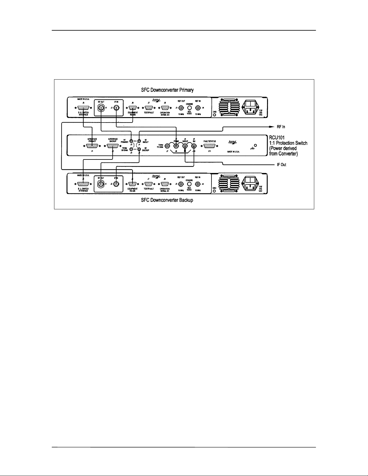
2.5 SFC Downconverter Interconnections
Figure 2-1 illustrates a typical interconnection of a SFC Downconverter with an RCU101 1:1
Protection Switch.
Figure 2-1. RCU101 Typical Interconnection with SFC Downconverters
2-2 TM054 - Rev. 4.0
Page 17
SFC4200/SFC1275G Synthesized Frequency Downconverter Operation
Section 3 - Operation
3.0 Theory of Operation
The SFC Downconverters have been designed to minimize the amount of hardware in the
system while maximizing performance. Spurious performance in the Downconverter is critical
and in particular, LO related spurious In-Band is nonexistent.
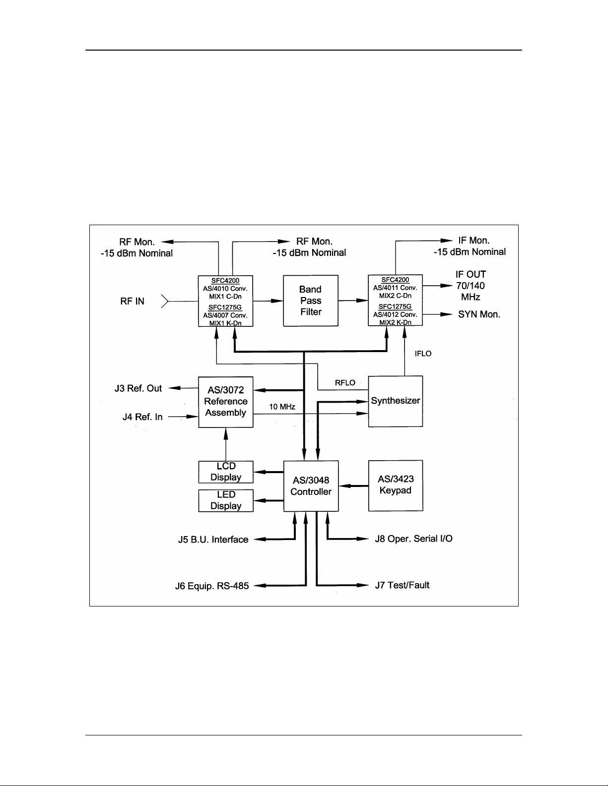
The SFC Downconverters are double conversion microwave Downconverters. The block
diagram (Figure 3-1) of the system includes the Signal RF Assembly, the Synthesizer Assembly,
the Reference Assembly, the Monitor and Control (M&C) Microcontroller, and Power Supply
Subsystem.
Figure 3-1. SFC Downconverter Block Diagram
3.1 Signal RF Assembly
The Signal RF Assembly is a subassembly that holds the first and second mixer converter
modules, and the IF Cavity Filter. The first and second mixer modules for the SFC4200 and
SFC1275G Downconverters are described below.
TM054 - Rev. 4.0 3-1
Page 18
Operation SFC4200/SFC1275G Synthesized Frequency Downconverter
3.1.1 AS/4010 Converter First Mixer C-Band Downconverter (SFC4200)
The First Mixer module of the C-Band Downconverter accepts the input and has 30 dB of digital
gain control. Performance specifications for the First Mixer are listed on Table 3-1.
Table 3-1. AS/4010 Converter First Mixer C-Band Downconverter (SFC4200)
Standard Band Extended Band
Input Frequency 3.62 – 4.2 GHz 3.400 – 4.200 GHz
Input Power -40 dB Nominal -40 dB Nominal
Input Return Loss > -20 dB > -20 dB
Input Impedance 50Ù 50Ù
Gain 8 – 10 dB 8 –10 dB
Gain Control None None
Output Frequency 1.0225 – 1.0626 GHz
(70 MHz)
0.9325 – 1.0125 GHz
(140 MHz)
P
Nominal -30 to –32 dBm -30 to –32 dBm
out
1.135 – 1.175 GHz
(70 MHz)
1.045 - 1.125 GHz
(140 MHz)
Output Impedance 50Ù 50Ù
LO Input 4.6625 – 5.2425 GHz @
+13 dBm for 70 MHz IF
4.5925 – 5.1725 GHz @
+13 dBm for 140 MHz IF
4.555 – 5.355 GHz @
+13 dBm for 70 MHz IF
4.485 – 5.285 GHz @
+13 dBm for 140 MHz IF
3.1.2 AS/4011 Converter Second Mixer C-Band Downconverter (SFC4200)
The Second Mixer module of the C-Band Downconverter accepts the IF from the First Mixer and
converts and amplifies it to the 70/140 MHz, 75Ù IF Output. The Second Mixer has 40 dB of
gain control. Performance of this converter assembly is listed in Table 3-2.
Table 3-2. AS/4011 Converter Second Mixer C-Band Downconverter (SFC4200)
Standard Band Extended Band
Output Frequency 50 – 90 MHz Standard
(100 – 180 MHz [Option 01])
50 – 90 MHz Standard
(100 – 180 MHz [Option 01])
Impedance 75Ù 75Ù
Output Return Loss
P
P1 dB +20 dBm +20 dBm
out
≥ 23 dB ≥ 23 dB
Gain 30 – 32 dB 30 – 32 dB
Input Frequency 1.0225 – 1.0625 GHz (70 MHz)
0.9325 – 1.0125 GHz (140 MHz)
Detected Output 0 - 10 VDC
(10 VDC @ -10 dBm Out)
3-2 TM054 - Rev. 4.0
1.135 – 1.175 GHz (70 MHz)
1.045 – 1.125 GHz (140 MHz)
0 - 10 VDC
(10 VDC @ -10 dBm Out)
Page 19
SFC4200/SFC1275G Synthesized Frequency Downconverter Operation
0 – 10 VDC (10 VDC @ -10 dBm In with
LO 1.1125 GHz @ +13 dB 1.225 GHz @ +13 dB
3.1.3 AS/4007 Converter First Mixer Ku-Band Downconverter (SFC1275G)
The First Mixer module of the Ku-Band Downconverter accepts the 10.95 – 12.75 GHz Downlink
and converts it to L-Band IF. Performance specifications for the First Mixer are listed on
Table 3-3.
Table 3-3. AS/4007 Converter First Mixer Ku-Band Downconverter
(SFC1275G)
Input Frequency 10.95 – 12.75 GHz
Input Power -40 dBm
Input Return Loss > -18 dB
Input Impedance 50Ù
Gain -5 to 6 dB
Gain Control None
Output Frequency 2.050 – 2.070 GHz (70 MHz) 2.100 –
2.180 GHz (140 MHz)
P
Nominal -34 to -35 dBm
out
Output Impedance 50Ù
LO Input 8.88 – 10.68 GHz @ +13 dBm for 70
MHz IF
8.81 – 10.61 GHz @ +13 dBm for 140
MHz IF
3.1.4 AS/4012 Converter Second Mixer Ku-Band Downconverter
(SFC1275G)
The Second Mixer module of the Ku-Band Downconverter accepts the IF from the First Mixer
and converts and amplifies it to the 70 MHz, 75Ù IF Output. The Second Mixer has 40 dB of
gain control. Performance of this converter assembly is listed in Table 3-4.
Table 3-4. AS/4012 Converter Second Mixer Ku-Band
Downconverter (SFC1275G)
Output Frequency 50 – 90 MHz Standard (100 – 180
MHz [Option 01])
Impedance 75Ù
Output Return Loss < -23 dB
P
P1 dB +20 dBm
out
Gain 34 – 35 dB
Input Frequency 2.050 – 2.090 GHz (70 MHz)
Pin Nominal -34 to 35 dBm
Detected Output
TM054 - Rev. 4.0 3-3
Page 20

Operation SFC4200/SFC1275G Synthesized Frequency Downconverter
0 dB Attenuation)
LO 2.0 GHz @ +13 dB
3.2 AS/3048 M&C Controller Assembly
The Controller PWB Assembly is the controller, which monitors the Operator Front Panel, and
Remote Input used to control the frequency, gain and provide the fault detection functions of the
converter. The AS/3048 hardware features an Intel 80C32 microprocessor (Refer to Figure 5-2).
Peripherals on the controller include the following:
12 Bit Digital to Analog Converter (DAC)
8 Channel/8 Bit Analog to Digital Converter (A/D)
RS-485 UART
RS-232, -422, -485 UART
LCD Port
8 Bit Addressable Synthesizer Bus
5 Bit Addressable Converter Bus
Static Memory
Nonvolatile Memory
Serial Nonvolatile Memory
Read-Only Memory (ROM)
The 12 Bit DAC provides the precise current to the PIN Diode Attenuators in the converter. The
value of attenuation is determined through look-up of calibration data stored in non-volatile
memory. 000 to FFF written to the DAC provides an output voltage of 0.3 V – 8.50 V
respectively.
The 8-channel A/D Converter allows the AS/3048 to monitor various voltages within the
converter. The input to the A/D is 0 to 5 VDC. Voltages monitored by the A/D include the
square-law voltages from the IF and Fault of the synthesizer which allows the controller to
calculate signal strengths.
The Equipment RS-485 UART is independent from the Operator UART. Dual UARTS allow
equipment to be tied together as a system while giving the operator a single remote point of
contact. The operator serial interface is configurable via jumpers found on the AS/3048. Refer
to Figure 5-3 for the location of the jumpers.
The various memories found in the AS/3048 provide for program storage and calibration value
storage. In the event that the operator is requested to perform a software revision, replacement
of the PROM (U11) will be required. This operation should be performed with the power off and
in a static-free environment.
3.3 Synthesizer Modules
The Synthesizer module used in SFC Downconverters are stand-alone modules that provide the
synthesized local oscillator and the fixed IF local oscillator for the first and second mixers in the
converter.
3-4 TM054 - Rev. 4.0
Page 21
SFC4200/SFC1275G Synthesized Frequency Downconverter Operation
3.3.1 Synthesizer Module (SFC4200)
The 10 MHz reference to the synthesizer is provided by the AS/3072 Reference Assembly.
Performance of the synthesizer is listed in Table 3-5.
Table 3-5. Synthesizer Module (SFC4200)
Standard Extended
RF LO Output Frequency 4592.5 - 5242.5 MHz 4.48 – 5.355 GHz
Step Size 125 kHz 125 kHz
Power Out +13 dBm +13 dBm
Spurious -70 dBc -70 dBc
Harmonics -20 dBc -20 dBc
Phase Noise
Note: Typical readings are 3
to 8 dB better than shown.
IF LO Output Frequency 1112.5 MHz 1.225 GHz
Spurious -70 dBc -70 dBc
Harmonics -20 dBc -20 dBc
-70 dBc @ 100 Hz
-80 dBc @ 1 kHz
-88 dBc @ 10 kHz
-95 dBc @ 100 kHz
-110 dBc @ 1 MHz
-70 dBc @ 100 Hz
-80 dBc @ 1 kHz
-88 dBc @ 10 kHz
-95 dBc @ 100 kHz
-110 dBc @ 1 MHz
3.3.2 Synthesizer Module (SFC1275G)
The 10 MHz reference to the synthesizer is provided by the AS/3072 Reference Assembly.
Performance of the synthesizer is listed in Table 3-6.
Table 3-6. Synthesizer Module (SFC1275G)
RF LO Output Frequency 11.91 – 12.73 GHz
Step Size 125 kHz
Power Out 13 – 15 dBm
Spurious -70 dBc In-Band
-82 dBc Out-of Band
Harmonics -20 dBc
Phase Noise
Note: Typical readings are 3
to 5 dB better than shown.
IF LO Output Frequency 2.0 GHz
Spurious -70 dBc
Harmonics -20 dBc
TM054 - Rev. 4.0 3-5
-60 dBc @ 100 Hz
-80 dBc @ 1 kHz
-84 dBc @ 10 kHz
-94 dBc @ 100 kHz
-110 dBc @ 1 MHz
Page 22

Operation SFC4200/SFC1275G Synthesized Frequency Downconverter
As shown in Figure 3-2, the phase noise plots showing synthesized and IF LO SSB Phase Noise
are representative of the actual phase noise of the SFC4200.
Figure 3-2. Phase Noise Plots
3-6 TM054 - Rev. 4.0
Page 23

SFC4200/SFC1275G Synthesized Frequency Downconverter Operation
3.4 AS/3072 Frequency Reference Assembly
The Frequency Reference Assembly provides high-stability, low-noise reference signals to the
synthesizer in the converter system. The assembly also provides a reference output signal and
a means of synchronizing the internal synthesizer to an external 10 MHz source.
Contained within the reference assembly is a 10 MHz SC-cut overtone ovenized frequency
standard. When an external reference is applied to the reference assembly, the internal
oscillator is turned off and the synthesizer attempts to phase-lock to the external 10 MHz.
The RF Signal to the reference assembly includes the following:
EXT REF IN: 10 MHz external reference signal input.
REF-OUT: 10 MHz OXO signal out, or when an external reference
is present, the external reference signal is available for
daisy chaining. In this manner, a single 10 MHz
reference can be supplied to the external reference of
one converter. In turn, the externally supplied 10 MHz
becomes available at the RF Output Port where it can
be supplied to the Reference Input of the next converter.
Int 10 MHz: 10 MHz signal for the synthesizer. Analog & Digital
Signal to the reference assembly includes the following:
Synthesizer Interface: 16-Pin Synthesizer Bus provides control of serial DAC
for the purpose of fine- tuning the 10 MHz Frequency
Reference.
Power Connector: 10-Pin Synthesizer Power Bus provides voltage for
operating the reference assembly.
3.5 AS/3228 Power Supply System
Power for the converter system is derived from a single 75-Watt 15 V switching regulator. With
15 VDC as the secondary voltage for the entire system, it is possible to operate the converter
from a wide range of primary voltages especially DC or battery supplies. In addition, the 15 VDC
can be heavily filtered with a single computer-grade capacitor. This will allow a high degree of
isolation from dirty primary power systems.
3.5.1 AS/3228 Output Board
The other voltages that are required in the system include +9 VDC and +5 VDC. All of these
voltages are filtered but unregulated. The +9 VDC, and –9.5 VDC are all derived from the
+15 VDC supply through DC/DC converters.
Power budgets in the converter are listed in Table 3-7.
TM054 - Rev. 4.0 3-7
Page 24

Operation SFC4200/SFC1275G Synthesized Frequency Downconverter
Table 3-7. SFC 1275G/SFC4200 Power Supply
+9 VDC +15 VDC +5 VDC
3048 Controller 300 ma 50 ma
3072 Ref. Assy 100 ma 300 ma
1st Mix U/C 120 ma 150 ma
2nd Mix U/C 350 ma 90 ma
Synthesizer 500 ma 850 ma
LCD Display 180 ma
Total Current 1.05 A 1.09 A 850 ma
Power 9.45 Watts 16.35 Watts 4.25 Watts
Total Power: 28 Watts * 85% Conversion Efficiency = 33 Watts Primary
Consumption
3.6 Frequency Accuracy
The 10 MHz reference in the SFC4200 was factory set for an accuracy of 1x10 E-9. The aging
specification of the reference is 5x10 E
-10
per day. In one year, the frequency may drift as much
as 6x10 E-9.
To correct an error in frequency, the operator should use the Reference Menu and adjust the
Frequency Offset in PPB. Scaling of the PPB Offset allows for ± 999 PPB of adjustment. An
increment of 1 PPB of the Reference Menu Offset will provide approximately 4.6 Hz correction in
the synthesizer frequency.
3.7 Amplitude Accuracy
The frequency response stability of the converter is not expected to vary more than the specified
accuracy of the converter over its normal life. In the event that the accuracy of the converter
gain should exceed an acceptable level, it is recommended that the unit be returned to the
factory for gain calibration. Calibration of the converter is performed under computer control.
Manually performing a calibration in the field is possible but may be considered impractical.
3-8 TM054 - Rev. 4.0
Page 25

SFC4200/SFC1275G Synthesized Frequency Downconverter User Interfaces
Section 4 – User Interfaces
4.0 User Interfaces
The Front Panel may be used to monitor and control the SFC Downconverters.
4.1 Front Panel User Interface
The Front Panel of the SFC Downconverters allows for complete M&C (including but not limited
to operation, calibration, and testing) of all parameters and functions via a Keypad, LCD Display
and Status LEDs.
The front panel layout is shown in Figure 4-1, showing the location and labeling of the front
panel. The front panel is divided into four functional areas: Front Panel LED Indicators, Front
Panel LCD Display, Front Panel Keypad, and Monitoring Ports, each described in Table 4-1.
Figure 4-1. SFC Downconverters Front Panel Controls and Indicators
Table 4-1. Front Panel User Interface
Item No. Description Function
1 Front Panel LED
Indicators
2 Front Panel LCD Display Displays SFC Downconverter operating
3 Front Panel Keypad Controls the up, down, left, and right movement
4 Monitoring Ports Allows the monitoring of the LO, and RF and IF
Refer to Section 4.1.1 for an itemized description
of these LEDs.
parameters and configuration data.
of the cursor in the Front Panel LCD Display.
Signals.
4.1.1 Front Panel LED Indicators
There are six LEDs on the SFC Downconverter Front Panel to indicate the operation status
(Table 4-2). The LED colors maintain a consistent meaning. Green signifies that the indication
is appropriate for normal operation, Yellow indicates operation status, and Red indicates a fault
condition that will result in lost communications.
TM054 - Rev. 4.0 4-1
Page 26

User Interfaces SFC4200/SFC1275G Synthesized Frequency Downconverter
Table 4-2. Front Panel LED Indicators
LED Color Function
POWER Green Indicates the presence of primary power and that the On/Off
Switch located on the rear of the chassis is in the On
Position.
EXT REF Green This LED indicates that an external 10 MHz reference signal
has been applied to the converter. A LO fault may occur
when the external reference is applied or removed. This
indicates that a change in the reference has occurred. This
fault can be cleared with a soft reset.
REMOTE Green The Remote LED indicates that the converter has been
addressed via the operator RS-232 Serial Interface, and that
a command has been received.
STANDBY Yellow This LED, when illuminated, indicates that the converter is
waiting to be off-line.
LO FAULT Red If the Synthesized LO or IFLO System of the converter
indicates an out-of-lock condition, the LO Fault LED will
illuminate. At this time, the Summary Fault Relay Contacts
will latch. If the LO Fault was due to an Intermittent Fault
Condition, the LO Fault will flash at one second intervals,
and fault checked may be reset.
SIG FAULT Yellow Signal Faults are used in switch configuration to indicate
switch status (when in the Backup Mode).
4.1.2 Front Panel LCD Display
The front panel display is a 2 line by 24-character LCD display that is capable of displaying five
fields of information in each menu window. While at the Root Menu, the Front Panel LCD
Display displays five fields, which are depicted by text captions around the display bezel. These
fields are listed below. The LCD display is a single entry window into the large matrix of
parameters that can be monitored and set from the front panel.
RX Frequency: The RX Frequency Field shows the frequency of the
selected input signal that will be converted to
70/140 MHz. When the cursor is placed in the
Frequency Field, and the Converter is in ‘SETUP’ Mode,
the frequency operation can be modified.
STATUS: The Status Field indicates the Mode of Operation or
Status of the Converter. The Modes of Operation
include ‘SINGLE’, ‘PRIMARY’, ‘BACKUP’, ‘SETUP’, and
‘OFF LINE’. The Single, Primary or Backup Status
indicates that there are no faults. It also identifies the
current configuration of the Converter. The Off Line
Status indicates that the Converter is off line due to a
fault condition.
Note: Because the backup ‘Learns’ the Frequency, Channel and Gain from the Prime,
changes to these fields are not allowed in the Backup converter.
4-2 TM054 - Rev. 4.0
Page 27

SFC4200/SFC1275G Synthesized Frequency Downconverter User Interfaces
CHANNEL: The Channel Field indicates which of 30 User-
Programmable (frequency and gain) Channels is
currently active.
GAIN: The Gain Field indicates the gain of the Converter. By
placing the cursor in the Gain Field, the gain can be
changed. Gain can be varied from +40 dB to 0 dB, and
may also be adjusted when the Converter is online.
RX SIGNAL: The Received Signal Field in the lower right-hand corner
of the display represents the signal strength of the RF
Input. The signal strength is displayed in dBm. The
Received Signal Strength Display is active when the
display is locked. Received signal strength accuracy is
± 3 dB.
Online Menus:
Single: Indicates that the converter is a standalone converter.
Backup: Indicates that the converter is the backup converter in a
redundancy system, either a 1:1 or a 1:8 system.
Primary: Indicates that the converter is the primary converter in a
Other Menus:
Setup: Allows the user to modify the fields from the Front Panel
Offline: Indicates that the converter is offline as a result of a
redundancy system, either a 1:1 or a 1:8 system.
Note: The online menus indicate no faults.
Display. To accomplish this:
1. Press <Enter> to obtain the cursor.
2. Move the cursor to the desired field.
3. Make the necessary modification.
4. Depress <Enter> to store the data.
5. Depress the <↑↑> Key to bring the converter to
an online status
6. Depress <Enter> again to turn the RF On.
Note: A faulted condition does not allow the
converter to be placed online. To access the Fault
Menu, press the Menu Button until the Converter
Status Menu is displayed.
fault condition.
Gain: The Gain Field indicates the gain of the converter. By
placing the cursor in the Gain Field, the gain can be
changed. Gain can be varied from +40 dB to 0 dB.
TM054 - Rev. 4.0 4-3
Page 28

User Interfaces SFC4200/SFC1275G Synthesized Frequency Downconverter
Note: Because the backup converter ‘Learns’ the Frequency, Channel, Gain and Input
Attenuation from the Prime Converter, changes to these fields are not allowed for the
Backup Converter.
4.1.3 Front Panel Keypad
The pushbutton keypad consists of (↑↑), (↓↓), (→→), (←←) keys, a Menu, and an Enter Key. Use of
these buttons is listed on Table 4-3.
Table 4-3. Front Panel Keypad
Key Function
Left/Right
Arrow Keys
(→→), (←←)
Up/Down
Arrow Keys
(↑↑), (↓↓)
ENTER The Enter Key will cause changes to Frequency, Status, and other operator-
MENU The Menu Key toggles the screens of the Front Panel LCD Display through
The Left/Right Arrow Keys are used to place the cursor in the desired field or
under the specific digit when moved to a number field. No changes in the
values or status can be executed from the left/right cursor movement.
The Up/Down Arrow Keys execute changes to numeric digits and can scroll
the status fields. To execute an actual change in status, gain or frequency,
the new number must be entered by depressing the enter pushbutton. Actual
operation to control frequency gain and status will be covered in detail below.
selected parameters to be executed. <Enter> also causes the status of the
converter to be saved into non-volatile memory.
the various menus (refer to Section 4.2).
4.1.3.1 Soft Reset
The microprocessor can be reset from the front panel by simultaneously depressing the
<MENU> and <ENTER>. This will cause the controller to reinitialize. The previously stored
Frequency, Gain and Input Attenuation information will be used during initialization.
4.1.4 Monitoring Ports
Refer to Section 5.11.
4.2 Menu Screens
The following Menu Screens are available on the SFC Downconverters (refer to Figure 4-2
through 4-4).
Root Menu: The Root Menu is the default screen showing
Frequency, Status, Gain, Rx Signal, and
Current Channel.
Converter Type: Displays Converter Model Number, Software
Revision and Serial Number.
Fault Menu: This menu shows latched fault conditions. It is
this menu that must be accessed to clear a
stored fault.
4-4 TM054 - Rev. 4.0
Page 29

SFC4200/SFC1275G Synthesized Frequency Downconverter User Interfaces
Utility Menu: Allows the operator to access the various utility
submenus described below:
Learn Menu (Backup Converter Only): Allows the operator to tell the Backup Converter
to ‘Learn’ about the Primary Converter.
Learn Status Menu (Backup Converter Only):Informs the operator of the status of the learning
process; successful or failed. If failed,
additional submenus inform the operator why.
Unit Configuration Menu: Allows operator selection of unit address (1 -
99), serial port baud rate (1200, 2400, 4800, and
9600 baud), Echo On/Off, specifies converter
configuration (Single, 1:1 or 1:8) and indicates
backup/primary configuration.
Reference Menu: This menu allows the operator to adjust the
reference source in PPB and to view the
number of hours the converter has been in
operation.
Output Attenuator Calibration Menu: The calibration menu allows a qualified operator
to calibrate the 20 dB output attenuator.
Note: Access to the Service Menu and the Calibration menus is denied when the
converter is online, as these submenus allow direct access to the synthesizer tuning.
TM054 - Rev. 4.0 4-5
Page 30

User Interfaces SFC4200/SFC1275G Synthesized Frequency Downconverter
Figure 4-2. Prime and Single SFC Downconverter Front Panel Menu Flowchart. SFC
Downconverter Menu Flow Charts (Prime and Single, Backup 1:1, and Backup 1:8)
4-6 TM054 - Rev. 4.0
Page 31

SFC4200/SFC1275G Synthesized Frequency Downconverter User Interfaces
Figure 4-3. Backup 1:1 SFC Downconverter Front Panel Menu Flowchart
TM054 - Rev. 4.0 4-7
Page 32

User Interfaces SFC4200/SFC1275G Synthesized Frequency Downconverter
Figure 4-4. Backup 1:8 SFC Downconverter Front Panel Menu Flowchart
4.2.1 Root Menu
The Root Menu appears after the Model Identification Screen, after power-up of the converter.
The four fields of this menu include Receive Frequency, Status, Gain Receive Signal (refer to
Figure 4-5).
4-8 TM054 - Rev. 4.0
Page 33

SFC4200/SFC1275G Synthesized Frequency Downconverter User Interfaces
Figure 4-5. Root Menu
The operation of these four fields is as follows:
4.2.1.1 Status
The Status field in the Root Menu provides an indication of the status of the selected channel.
The Status fields indicate the converter’s configuration (Single, Primary, Backup) if the converter
is Online; Setup, if the converter is in setup mode; or Offline if there is a fault in the converter
which would prevent it from being placed online. The Status field also indicates under which
channel number the Frequency and Gain information is being stored.
The Root Menu will appear by default upon power-up. Prior to putting a converter online, the
correct frequency should have been selected. A properly functioning converter that has no faults
and is ready to be placed online will have the status indicated at ‘Setup.’ The structure of the
Status prompt is as follows:
{Status}{Channel No.}
SINGLE: Indicates that the converter is in a standalone
configuration and that when presented with an input
signal of the specified frequency, will generate an output
signal with the specified conversion gain.
PRIMARY: Indicates that the converter is in a switched
configuration, and that when presented with an input
signal of the specified frequency, is capable of
generating an output.
BACKUP: Indicates that the converter is in a switched
configuration, and that when presented with an input
signal of the specified frequency, is capable of
generating an output.
SETUP: Indicates that the front panel is unlocked and the
operator has free control of the Gain and Frequency
fields.
OFF LINE: The converter has experienced a fault and has placed
itself off line. Off Line Status is the same as out-ofservice. The fault will have to be cleared and/or the
failed component replaced.
The ‘Channel No.’ field of the Status prompt includes the numbers from 01 to 30 to indicate
which stored channel is being programmed or recalled with Frequency and Gain information.
TM054 - Rev. 4.0 4-9
Page 34

User Interfaces SFC4200/SFC1275G Synthesized Frequency Downconverter
4.2.1.2 Set/Change Status
Status manipulation is performed via the cursor position and the <ENTER> Key. To modify the
operating status of the converter, first determine if the cursor is blinking. If the cursor is not
blinking, press <ENTER> to turn on the blinking cursor and position it under the first letter of the
status field. This is the ‘home’ position in which the cursor is placed in order to execute a change
in status.
For example, to place the converter online (single) from setup, insure that the cursor is present.
Press either the (↑↑) or (↓↓) Keys and scroll through the selections which will include Single
Indicator or Setup. When the selection for Single Indicator has been reached, depress
<ENTER>. The flashing cursor will turn off, and the Standby LED will turn off and the unit
placed in service.
The gain of the online converter can be changed by depressing <ENTER>, using the (→→) or (←←)
Keys to position the blinking cursor in the Gain Field and then using the (↑↑) or (↓↓) Keys to
change the gain. Once the cursor is in the Gain Field, it cannot move into any other field. This
prevents a change of frequency while online. Depressing <ENTER> will save the selected gain,
turn the cursor off, and lock the front panel.
To place a single or a primary converter in setup, from online and front panel locked (no blinking
cursor visible), depress <ENTER>. A blinking cursor will be positioned in the Status Field. Use
the (↑↑) or (↓↓) Keys to select ‘SETUP’ (the Standby LED is on). Use the (↑↑) or (↓↓), and the (→→) or
(←←) Keys to select and change the desired control field. Depress <ENTER>. The Standby
Indicator will be turned off, the changed parameter will be stored to memory, and the cursor will
be placed in the Status Field. Use the (↑↑) or (↓↓) Keys to select the online indicator and depress
<ENTER>. The new converter settings will be executed, the RF will be turned back On, and the
front panel will be locked.
Note: The Backup Converter ‘Learns’ about the Prime(s) and therefore cannot be placed
in Setup Mode.
An optional method of changing the Frequency and Gain is to use the programmed channels.
To select a programmed channel, move the cursor to the Channel Number part of the field after
the unit has been placed into Setup, and scroll through the selections. As the number changes,
the Frequency and Gain Fields will change to indicate the stored values (Note that no changes to
the Frequency or Gain will take place unless the operator depresses the <ENTER> Key). If
<ENTER> is depressed, the new channel will be selected as the default channel. To modify or
to program the stored values, move the cursor to the appropriate field and make the change. To
store the value to non-volatile memory, depress <ENTER>. An asterisk (*) will be displayed to
the right of the channel field to indicate a Channel Store Operation has taken place. In case of a
power failure, the current operating parameters are stored in non-volatile memory for automatic
Downconverter configuration, which takes place upon power restoration.
4.2.1.3 Frequency
To set or to change the Frequency, perform the steps listed in Section 4.2.1.2 to place the
converter into Setup Mode. Select the Channel Number that contains the programmed
frequency, or is the channel for which a previously programmed frequency needs to be changed.
While at the desired channel number, move the cursor to the Frequency Field. Position the
cursor under the desired digit to be changed and make the change with the (↑↑) or (↓↓) Keys. To
store the new frequency into memory for the selected channel, depress <ENTER>.
4-10 TM054 - Rev. 4.0
Page 35

SFC4200/SFC1275G Synthesized Frequency Downconverter User Interfaces
The cursor will move to the Status Field. Place the unit back in service by selecting the Single
Indicator in the Status Field and then depressing <ENTER>. An asterisk (*) will be displayed to
the right of the Channel Field to indicate a Channel Store Operation has taken place. Otherwise,
upon power-up or recalling the desired channel will cause the frequency to revert to the stored
frequency value. The frequency selection to the synthesizer is executed when <ENTER> is
depressed. The LO Fault Circuitry is active so that an LO Fault associated with a specific
frequency of operation can be determined while the converter is in Setup Mode.
4.2.1.4 Gain
The Gain of a single or primary converter can be changed while the converter is both Online and
in Setup mode. To change the Gain at any time, position the cursor under the digit to be
changed in the Gain field and increment or decrement the number using the (↑↑) or (↓↓) Keys.
The Gain change will be made at this time. To store the new Gain into the non-volatile memory
for the currently selected channel number, depress <ENTER>. An asterisk (*) will be displayed
to the right-hand corner of the Channel Field to indicate a Channel Store operation has taken
place. Otherwise, upon power-up, or recalling the desired channel causes the Gain to revert to
the Stored Gain value. To prevent data errors while the unit is online, changes as directed from
the front panel are dampened in execution to the actual hardware so as not to generate an
abrupt jump in power.
4.2.2 Converter Type Menu
The Converter Type Menu (Figure 4-6) displays the Converter Type, Software Revision Level.
Figure 4-6. Converter Type Menu
4.2.3 Switch Fault Menu
This menu is applicable to the Backup 1:1 and Backup 1:8 Converters. If there are no switchrelated faults, the menu will say so. If there are switch-related faults, using the (↑↑) Key will scroll
through the various reasons for the Switch Fault (refer to Figure 4-7).
Figure 4-7. Switch Fault Menu
TM054 - Rev. 4.0 4-11
Page 36

User Interfaces SFC4200/SFC1275G Synthesized Frequency Downconverter
These include the following:
Prime Not Learned: The Backup has not learned about the Prime(s).
Prime Polling Error: Either the Prime did not respond to the Backup’s
periodic polling, or something in the Prime’s
configuration has changed since the last time the
backup was told to ‘Learn.’
Note: Changing the Prime after the Backup has ‘Learned It’ will cause a Switch Fault until
the Backup is told to ‘Relearn’ the Prime(s).
Prime Relay Fault: The Backup has detected that the Switching Relay did
not switch when told to do so.
Note: Any Switch Fault will cause the Signal Fault LED on the Backup to illuminate. It
will also cause the Error LED on the 1:8 Switch to illuminate.
4.2.4 Converter Faults Menu
To access the Converter Faults Menu, depress <ENTER>. If there are no stored faults, the fault
menu will indicate ‘Stored Faults, None.’ If there are stored faults, the menu will indicate that
stored faults have been recorded.
To interrogate the nature of the stored faults, depress <ENTER> again. The stored fault screen
format is as shown in Figure 4-8.
Figure 4-8. Stored Faults Menu
The Fault descriptions are indicated as follows:
LO: Indicates a fault in the synthesizer and the number of fault detections
(up to 255).
SIG: N/A
To clear the faults, depress <ENTER>.
4-12 TM054 - Rev. 4.0
Page 37

SFC4200/SFC1275G Synthesized Frequency Downconverter User Interfaces
4.2.5 Utility Access Menus
Depress <Menu> from the Fault Menu to access the Utility Access Menu. To gain access to the
various utility menus of the converter, depress <ENTER>. The Utility Access Menu will appear
as shown in Figure 4-9.
Figure 4-9. Utility Access Menu
Pressing <ENTER> will scroll to the first Utility Menu which is the Configuration Menu for
Primary and Single Converters, or the Learn Menu for Backup Converters. Depressing <MENU>
again will scroll to the second Configuration Menu. Use <MENU> to scroll through the
Reference Menu, Status Menu, and Output Attenuator Calibration Menu. Calibration Menus
represent those alignments, settings and various operating parameters that are set in nonvolatile memory. Most calibration is done via the RS-232 Interface, but those same parameters
can be accessed via calibration menus.
Note: The Calibration Menu is denied when the converter is online, as these submenus
allow direct access to the synthesizer tuning.
For a 1:1 Backup, the menu will appear as shown below in Figure 4-10.
Figure 4-10. Menu for a 1:1 Backup
For a 1:8 Backup Converter, the Menu will appear as shown below in Figure 4-11.
Figure 4-11. Menu for a 1:8 Backup
TM054 - Rev. 4.0 4-13
Page 38

User Interfaces SFC4200/SFC1275G Synthesized Frequency Downconverter
4.2.6 Switch Configuration Menu
This Menu (refer to Figure 4-12) is applicable for a 1:8 Backup Converter. It allows the operator
to specify the priority of the various converters. The priority is as follows: 1 (Highest Priority)
through 8 (Lowest Priority), and 0 (No Priority, the Backup will ignore the Prime).
Figure 4-12. Switch Configuration Menu
The Arrow Keys are used to move left and right, and increase or decrease a converter’s priority.
When all of the priorities have been set, pressing the <ENTER> causes the Backup to accept the
entries and store them in Non-Volatile RAM. Pressing <MENU> will scroll to the next menu.
4.2.7 Learn Menu (Backup Converter Only)
Depressing <MENU> will scroll to the Configuration Menu. Depressing <ENTER> will cause the
Backup Converter to ‘Learn’ about the Primary Converter (Figure 4-13).
Figure 4-13. Learn Menu
The screen automatically scrolls to the Learn Status Menu
4.2.8 Learn Status Menus (Backup Converter Only)
The Automatic Learning in Progress Window (Figure 4-14) indicates that the Backup Converter
is polling the Prime Converter in order to learn about it.
Figure 4-14. Automatic Learning in Progress Window
4-14 TM054 - Rev. 4.0
Page 39

SFC4200/SFC1275G Synthesized Frequency Downconverter User Interfaces
The window shown in Figure 4-15 indicates that the Backup Converter was successfully able to
‘Learn’ about the Primary Converter.
Figure 4-15. Automatic Learning Successfully Completed Window
The following window (Figure 4-16) indicates that the Backup Converter was not able to learn
about the Prime Converter.
Figure 4-16. Automatic Learning Failed Window
When the <Menu> key is pressed, the Backup Converter will provide more information about the
failure. This information includes the following:
No Response: The Prime Converter did not respond.
Invalid Response: The Prime Converter responded, but the Backup
Converter did not receive the message clearly.
Incompatible Converter: The Backup Converter is not capable of backing up the
Prime Converter.
4.2.9 Configuration Menu
The ID # Field allows the operator to establish an ID Number for the Operator Serial Interface.
Move the cursor to this field and increment or decrement to change the ID Number. Press
<ENTER> to store the value.
The field for Baud Rate allows the operator to select baud rates from 1200 to 9600 bps. Move
the cursor to this field and increment or decrement the value. Depress <ENTER> to store the
value and reinitialize the serial port.
Note: Serial data format is fixed to provide 8 data bits, 1 start bit, 1 stop bit, no parity.
The Echo Field is for the Operator Serial Port Interface. When the Echo is in the On State, the
converter will echo all the data it receives back to the Host Terminal. When more than one
converter is connected to the same bus (RS-485), the Echo must be Off. Move the cursor to this
field to change the Echo On/Off Status. Press <ENTER> to store the value.
TM054 - Rev. 4.0 4-15
Page 40

User Interfaces SFC4200/SFC1275G Synthesized Frequency Downconverter
The Config Field (Configuration) indicates the status of the converter and is defined as follows:
SNGL: Indicates that the converter is a standalone unit.
1:1: Indicates that the converter is in a one-for-one backup
configuration.
1:8: Indicates that the converter is in a one-for-eight backup
configuration.
Figure 4-17. Configuration Menu
4.2.10 Reference Menu
The Reference Menu (Figure 4-18) allows the operator to fine-tune the 10 MHz ovenized
frequency standard over a range of ±999 PPB. This menu also contains a clock that indicates
the total number of hours the unit has been in operation since the reference oscillator was first
installed.
The Reference Menu is as follows:
Figure 4-18. Reference Menu
OPPB: This field contains the offset of the 10 MHz frequency
standard in PPB. When the oscillator is first installed, or
when the oscillator has been coarse-calibrated, this
value will first be set to 000 PPB offset. The operator
can change the offset manually by placing the cursor in
this field and incrementing or decrementing the value.
Press <ENTER> to store the value.
ELAPSED HOURS: This field indicates the number of hours the converter
has been in operation since the frequency standard was
first installed.
4-16 TM054 - Rev. 4.0
Page 41

SFC4200/SFC1275G Synthesized Frequency Downconverter User Interfaces
4.2.10.1 Reference Offset
The Reference Offset Field of the Reference Menu allows the operator to adjust the frequency of
the 10 MHz High Stability Internal Reference and vary the output of the Synthesized RF LO by ±
999 Parts per Billion (PPB). One part per billion represents a change of 1 Hz per GHz (1 billion
Hz) of output frequency. Measured at the LO MON port, 1 PPB represents 4.6 Hz change in
frequency for a LO Output of 4.6625 GHz. Note that 1 PPB changes the frequency of the LO
MON or Converted IF or RF Output by 4.6 Hz as well. Thus, each unit of PPB will allow a
change in accuracy of the converter of 1 x 10⁻⁹.
The exact frequency of the LO Output can be calculated from the displayed frequency on the
converter front panel as follows:
C-Band Downconverter (70 MHz IF): LO MON = Rx Freq. + 1042.5 MHz
C-Band Downconverter (140 MHz IF): LO MON = Rx Freq. + 972.5 MHz
C-Band Downconverter Extended (70 MHz IF): LO MON = Rx Freq. + 1155 MHz
C-Band Downconverter Extended (140 MHz IF): LO MON = Rx Freq. + 1085 MHz
Ku-Band Downconverter (70 MHz IF): LO MON = Rx Freq. – 2070.0 MHz
Ku-Band Downconverter (140 MHz IF): LO MON = Rx Freq. – 2140.0 MHz
The RF Monitor output can be measured with a frequency counter of known calibration.
4.2.10.2 Reference Stability
The stability of the 10 MHz Reference is related to the temperature of 10 MHz crystal inside the
unit. A proportionally controlled oven around the crystal maintains the temperature in the oven
to 0.1°C. In addition, the precise temperature that the oven maintains has been determined
empirically for each crystal during manufacturing. As long as the ambient temperature stays
within limits (0 - 50°C) the reference will maintain stability of greater than 1 x 10
4-18).
-8
(refer to Figure
Figure 4-19. Typical Reference Aging vs. Time
TM054 - Rev. 4.0 4-17
Page 42

User Interfaces SFC4200/SFC1275G Synthesized Frequency Downconverter
Long term stability of the reference is affected by factors other than temperature. Over days and
months, the frequency of the reference will drift at a rate specified as aging. Typical aging rates
of 1 to 5 parts in 10
-10
per day are typical in a crystal that has been stabilized for a few weeks.
The first month of operation for any crystal is a time where drift due to aging can be excessive.
The typical aging curve provides insight into the exponential decay in aging rate for a 10 MHz
Reference. Converters shipped from the factory have had their reference oscillator aged for a
minimum of 30 days and in addition, the aging rate has been verified in the final week to within
tolerance. However, converters that have been in storage or powered off for a period of several
weeks will exhibit a phenomenon whereby the aging curve return to the slope shown for zero
days of aging. This aging reset in not well understood but the manufacturers of crystals believe
it to be related to a gradual relaxation of the molecular makeup of the quartz substrates and the
conductive films deposited on the quartz.
The rule of thumb when checking the frequency accuracy of the converter is to make sure that
the crystal has stabilized before attempting any adjustment. For units that have been in storage
or shipment for more than a week, allow several days of operation before verifying the accuracy.
For this reason, converters shipped from Radyne ComStream Corporation are typically poweredup until the final day before shipment. In addition, the accuracy and aging rate are verified
immediately prior to shipment.
For a converter that has been powered-up for several months, the operator can assume an aging
rate of several PPB per month. If the aging rate has been established, the station operator can
make calculated adjustments from the reference offset menu at timed intervals.
4.2.11 Output Attenuator Calibration Menu (locked, not user accessible)
The Output Attenuator (Figure 4-20) can be calibrated over 0 – 40 dB of attenuation in 1 dB
increments over frequency bands centered 50 MHz apart.
Figure 4-20. Output Attenuator Calibration Menu
Freq: Shows the 50 MHz Frequency Band that is currently
being calibrated. While in this menu, selecting or
changing a Frequency Cal Band will cause the
synthesizer to change to that center frequency. The
frequency band selection can be incremented or
decremented by placing the cursor on the current
frequency and depressing the Up or Down cursor
buttons.
Atten: This number, located under the Status Field
nomenclature, indicates the location for or value of
attenuation for which the operator is calibrating the
Digital-to-Analog Converter (DAC) Value. The Atten
value can be increased by depressing <ENTER>.
When <ENTER> is depressed, the DAC Value displayed
is stored into non-volatile memory and the Atten digit is
increased to the next value. At 20, this digit rolls over to
0.
4-18 TM054 - Rev. 4.0
Page 43

SFC4200/SFC1275G Synthesized Frequency Downconverter User Interfaces
DAC Value: Place the cursor in the DAC Value Field and use the (↑↑)
and (↓↓) Keys to increment or decrement the DAC Value.
Simultaneously, the display will indicate the DAC
Voltage. In a normal calibration arrangement, the
operator will be monitoring the power output of the
converter with a Spectrum Analyzer. When the desired
value of calibration is reached, the operator will depress
<ENTER> which stores the value and increments the
Atten Level to the next number. The DAC value will
revert to the stored value for that location. This keypad
arrangement is designed to allow for manual calibration
with limited wear-and-tear on the operator who may be
attempting manual calibration of the attenuator in the
field.
To perform the calibration, the technician needs to apply
an RF signal to the Downconverter at the frequency
indicated in the Freq. Field. A spectrum analyzer or
power meter is connected to the output and the DAC
Value is incremented up or down until the required gain
is indicated by the spectrum analyzer. Finally, the
correct DAC is stored by depressing <ENTER>. The
attenuator setting is incremented to the next location, or
in this case, 01 dB. The process is repeated until 20 dB
is reached and then the next frequency is selected. The
frequency of the signal generator must be changed and
the process repeated. This menu is not displayed when
the converter is online.
4.3 Serial Protocol
The SFC Downconverter Serial Protocol allows a remote operator to gain control the converter.
Through the serial protocol described, the remote operator can control gain, frequency,
calibration, status and fault isolation. The Serial Port is factory-set to communicate as the DCE
at 9600 baud with 8 data bits, 1 start bit, 1 stop bit and no parity bits.
4.4 Command Structure
The serial command structure uses an ASCII character string format that enables serial control
through the use of a ‘dumb terminal.’ To differentiate a proper command string from noise, all
serial commands have a header followed by the specific command characters, followed by
numeric values where required, and are terminated by a character return <cr>. The basic
command structure is as follows:
@{Unit Address/}{command}{numerical value(s)}<cr>
For the following examples, a unit address of 01 is assumed.
TM054 - Rev. 4.0 4-19
Page 44

User Interfaces SFC4200/SFC1275G Synthesized Frequency Downconverter
4.5 Control Commands
Control Commands are those commands that alter the setup or operating parameters of the
converter. These commands primarily control Frequency and Gain. Frequency and Gain can be
altered on the current channel number that is indicated on the front panel, or the other channels
0-30 which are not selected can be programmed without affecting the current operating channel.
The final method to change Frequency and Gain is by remotely recalling the Gain and
Frequency Settings that have been programmed in another channel. The various Control
Commands are applicable for a variety of converter configurations. After each of the following
control commands appears an abbreviation in parenthesis that identifies which converter
configurations are valid for that particular control command. The applicable converter
configurations are as follows:
S: Single Converters
P1:1: Primary Converter 1:1 Switch
B1:1: Backup Converter 1:1 Switch
P1:8: Primary Converter 1:8 Switch
B1:8: Backup Converter 1:8 Switch
ALL: All Converters
4.5.1 Set Current Channel Frequency Command (S, P1:1, P1:8)
The Set Current Channel Frequency Command alters the stored frequency of the current
channel. The set frequency command is as follows:
@01/SETFREQffff.t<cr>
The frequency numerical values include four digits for MHz and one digit "t" which indicates the
resolution in 125 kHz steps. The values of "t" are as follows:
t Frequency
0 000 kHz
1 125 kHz
2 250 kHz
3 375 kHz
4 500 kHz
5 625 kHz
6 750 kHz
7 875 kHz
Valid frequency ranges are 3400.000 though 4200.000 kHz (SFC4200), and 10950.000 MHz
through 12750 MHz (SFC1275G). Frequencies outside this range, or frequencies that are of an
invalid form will be responded to by the ‘illegal frequency’ prompt. If the synthesizer is unable to
tune to the desired in-band frequency, the converter will indicate a LO Fault Condition status
indication and will change to an off-line or out-of-service indication.
4.5.2 Set Current Channel Gain Command (S, P1:1, P1:8)
To permanently change the programmed gain of the current channel, use the Set Current
Channel Gain Command. The command is as follows:
@01/SETGAINsgg.g<cr>
The numeric value ‘s’ indicates the ‘plus’ sign (+). The numeric value ‘g’ consists of three digits
indicating gain from 0 to 40 dB.
4-20 TM054 - Rev. 4.0
Page 45

SFC4200/SFC1275G Synthesized Frequency Downconverter User Interfaces
4.5.3 Set Channel Command (S, P1:1, P1:8)
The Set Channel Command allows the remote operator to change the Channel and thus the
Gain and Frequency of the converter to one of the 30 preprogrammed channels. To change
channels, use the following format:
@01/SETCHANcc<cr>
Where ‘cc’ represents a channel number from 01 through 30.
4.5.4 Store Current Channel Settings (S, P1:1, P1:8)
After altering the Frequency or Gain of the currently selected channel, the remote operator can
store these settings into non-volatile memory by issuing the Store command as follows:
@01/STORE<cr>
4.5.5 Remote Help Menu (All)
All serial commands and serial protocol can be listed for the remote operator by entering the
Help command as follows:
@01/HELP<cr>
4.5.6 Status Command
Prior to issuing a remote command, the remote operator may first wish to determine the current
status of the converter. To request status, issue the following command:
@01/STATUS<cr>
A single converter will issue the following string of information:
Configuration: {Single}
Status: {Online, Faulted, Setup}
Channel: {Current Channel No.}
Frequency: {Current Frequency}
Gain: {Current Gain}
RSS: {Text, Signal Value}
Stored Fault: {None, Faulted}
Reference: {Internal/External}
A Converter in a 1:1 Switch Configuration will issue the following string of information:
Converter Configuration: {One for One Primary, One for One Backup}
Switch Configuration: {Auto, Manually Selected, Manually De-selected}
Status: {Standby, Online, Faulted}
Channel: {Current Channel}
Frequency: {Current Frequency}
Gain: {Current Gain}
RSS: {Text, Signal Value}
Stored Fault: {None, Faulted}
Reference: {Internal/External}
TM054 - Rev. 4.0 4-21
Page 46

User Interfaces SFC4200/SFC1275G Synthesized Frequency Downconverter
A Primary Converter in a 1:8 Switch configuration will issue the following string of information:
Switch Configuration: {Auto, Manually Selected, Manually De-selected}
Primary Converter Number: {01, 02, 03, 04, 05, 06, 07, 08}
Status: {Available, Faulted}
Channel: {Current Channel}
Frequency: {Current Frequency}
Gain: {Current Gain}
RSS: {Text, Signal Value}
Stored Fault: {None, Faulted}
Reference: {Internal/External}
A Backup Converter in a 1:8 Switch Configuration will issue the following string of information:
Hot Converter: {Identifies the Converter number with the highest priority
in reference to the Switch}
Frequency: {Current Frequency}
Gain: {Current Gain}
RSS: {Text, Signal Value}
Stored Faults: {None or Faulted}
One For Eight Switch Status: {Indicates the status of each prime converter}
Switch is in: {Manual Mode, Auto Mode}
Prime 1
Prime 2
Prime 3
Prime 3
Prime 4
Prime 5
Prime 6
Prime 7
Prime 8
Backup is: {Available, Online for Converter [1…8]}
Notes: If none of the converters are faulted, the ‘Hot Converter’ will be the converter for
which the backup is in hot standby.
If one or more of the converters have faulted, the ‘Hot Converter’ will be the converter that
the backup is currently replacing.
If the status indicates that the backup is available, then the backup is not currently
replacing any of the primes.
4.5.7 Clear Faults Command (All)
The operator may wish to remotely clear any stored faults. Issue the following command:
@01/CLRFAULT<cr>
4.5.8 Auto Mode Command (P1:1, B1:1, B1:8)
This command allows the operator to put the switch back into Auto Mode. Issue the following
command:
@01/AUTO<cr>
4-22 TM054 - Rev. 4.0
Page 47

SFC4200/SFC1275G Synthesized Frequency Downconverter User Interfaces
Note: For a 1:1 Switch configuration, if the front panel switch is accidentally left in
Manual Mode, then the following action should be performed: from the Remote Port, send
a manual command to the converter that is ‘Manually Deselected,’ i.e.; the one that is NOT
selected. Then send an Auto Command to the same converter and the switch change
back to Auto Mode.
For a 1:8 Switch configuration, send the Auto Mode command to the backup converter.
4.5.9 Manual Mode Command (P1:1, B1:1)
This command allows the operator to force the switch to put the converter online and keep it
there. This command simulates the manual selection switch on the front panel. Issue the
following command:
@01/MANUAL<CR>
Note: For a 1:1 Switch configuration, if the front panel switch is accidentally left in
Manual Mode, then the following action should be performed: from the Remote Port, send
a manual command to the converter that is ‘Manually Deselected,’ i.e.; the one that is NOT
selected. Then send an Auto Command to the same converter and the switch change
back to Auto Mode.
4.5.10 Manual Backup Command (B1:8)
This command allows the operator to force the switch to put the Backup online for the specified
converter and keeps it there. This command simulates the manual backup selection switches on
the front panel of the 1:8 Switch. Issue the following command:
@01/MANBACKn<cr>
Where:
n = 0 Forces the Backup to Standby Mode, all Primes are online
n = 1 – 8 Specifies the converter that the Backup is to replace
4.5.11 Set Stored Gain For a Specified Channel (S, P1:1, P1:8)
This command allows the user to set the Stored Gain for a specified channel other than the
current one.
@01/RAMGAINccsgg.g<cr>
4.5.12 Set Stored Frequency For a Specified Channel (S, P1:1, P1:8)
This command allows the user to set the Stored Frequency for a specified channel other than the
current one.
@01/RAMFREQccffff.t<cr>
4.5.13 Erase (All)
This command allows the user to erase the Stored Status, Frequency and Gain Information the
next time the unit is reset.
@01/ERASE<cr>
TM054 - Rev. 4.0 4-23
Page 48

User Interfaces SFC4200/SFC1275G Synthesized Frequency Downconverter
4.5.14 Restart (All)
This command allows the user to reset/restart the converter.
@01/RESTART<cr>
4.5.15 Data (All)
This command will cause the converter to display the applicable data formats for the various
commands.
@01/DATA
4.5.16 Learn (B1:1, B1:8)
In a 1:1 Switch configuration, this command will cause the backup converter to ‘Learn’ about the
Prime converter.
In a 1:8 configuration, the Backup converter will ‘Learn’ about the Prime converters that have a
priority > 0. As the Backup converter polls the Prime(s), the learning status will be output via the
serial port.
@01/LEARN
4.5.17 Show Priority (B1:8)
This command causes the backup converter to display the priority settings for all 8 of the prime
converters.
@01/SHOW PRI (1:8 configuration only)
4.5.18 Set Priority (B1:8)
This command is used to set the priorities of converters 1 to 8 respectively where:
0 = No priority (the converter will be ignored)
1 = Highest priority
8 = Lowest Priority
@01/SETPRIabcdefgh (1:8 configuration only)
For example: @01/SETPRI47300000 will cause the following to occur:
Converter 1 will have priority 4;
Converter 2 will have priority 7;
Converter 3 will have priority 3;
Converters 4 through 8 will be ignored.
4-24 TM054 - Rev. 4.0
Page 49

SFC4200/SFC1275G Synthesized Frequency Downconverter User Interfaces
4.6 SFC Downconverter Operator Quick Reference Guide
Table 4-4 lists all of the SFC Downconverter Commands.
Note: In all cases the commands are preceded by a valid address “@01/”.
Table 4-4. SFC Downconverter Operator Quick Reference Guide
@01/HELP Displays all available user commands.
@01/DATA Displays data formats associated with commands.
@01/STATUS Displays converter status.
@01/SHOWRSS Display received signal strength.
@01/CLRFAULT Clears latched faults.
@01/ERASE Erases stored status, frequency, and gain data upon the next reset.
@01/RESTART Restarts the converter.
@01/SETGAIN Sets the gain for the current channel.
@01/SETCHAN Sets the current channel.
@01/SETFREQ Sets the frequency for the current channel.
@01/STORE Saves all data under the current channel.
@01/RAMGAIN Sets the gain for another/alternate channel.
@01/SETATTN Sets the input attenuator for the current channel.
@01/RAMFREQ Sets the frequency for another/alternate channel.
@01/AUTO Puts the switch back into Auto Mode. Simulates the middle position
of the front panel switch (1:1, 1:8 only).
@01/MANUAL Forces the switch to place the converter online and keeps it there.
Simulates the manual selection switch on the front panel (1:1, 1:8
only).
@01/SHOWPRI Displays priority settings for the 8 prime converters (1:8 only).
@01/SETPRIabcdefghSets priorities of converters 1 through 8 respectively (1:8 only).
@01/LEARN Causes the backup converter to learn about the prime converter(s)
(1:1, 1:8 only).
@01/MANBACKn Forces the backup to replace the specified converter (1:8 only).
TM054 - Rev. 4.0 4-25
Page 50

Page 51

SFC4200/SFC1275G Synthesized Frequency Downconverter Electrical Interfaces
Section 5 – Electrical Interfaces
5.0 SFC Downconverter Connections
All SFC Downconverter connections are made to labeled connectors. Any connection interfacing
to SFC Downconverters must be the appropriate mating connector. Refer to Figure 5-1 below
for the various connector locations.
Figure 5-1. SFC Downconverter Rear Panel
5.1 Power
Located on the right-rear side of the SFC Downconverter Rear Panel is the AC Power Input
Connector. This connector is an IEC 320/C13 Power Entry Module. The unit is powered from a
100 – 240 VAC, 50 – 60 Hz source. Maximum unit power consumption is 50 W. The switch
turns power on and off to the unit. A chassis ground connection can be made at the #10 size
stud located to the lower left of the AC Power Connector.
The power cord/connector for the SFC Downconverter is a supplied item.
5.2 RF In (J1)
The RF In (J1) is the Primary RF Input of the SFC Downconverters. It is an N-Type Female
Connector for the SFC4200, and an SMA Female Connector for the SFC1275G.
5.3 IF Out (J2)
The IF Out Connector (J2) is the 75 Ohm BNC-F Connector. Outputs are within 50 – 90 MHz for
standard units and 100 – 180 MHz for units equipped with 140 MHz.
5.4 10 MHz Ref Out (J3)
The 10 MHz Reference Out (J3) is the 50 Ohm BNC-F Connector that provides a 10 MHz
squarewave, 50 Ohm AC coupled reference output signal at 0 dBm. In normal operation (no
external reference) this output is synchronous with the internal high stability 10 MHz reference.
5.5 10 MHz Ref In (J4)
The Reference Input BNC-F connector (J4) at the rear of the converter allows the operator to
synchronize the synthesizer of the converter to an external 10 MHz reference. When an external
reference is properly applied to the reference input, the external reference LED will illuminate on
the front panel.
5.6 B. U. Switch Interface (J5)
The Backup Switch Interface (J5) is a D Sub 15 Pin Connector that connects each converter with
the RCU101 or RCU108 Backup Switch Unit. This cable is not daisy-chained between
converters, but serves as a direct link for each converter in the configuration, whether they are
TM054 - Rev. 4.0 5-1
Page 52

Electrical Interfaces SFC4200/SFC1275G Synthesized Frequency Downconverter
the individual online converters or the backup unit. This interface finds use in both the 1:1 and
1:N configuration type switches. The pinouts of the switch is listed in Table 5-1.
Table 5-1. J5 – Backup Switch Interface – D Sub 15-Pin Connector
Pin No. Signal Description
1 N.O. Form-C contact summary fault
normally open contact
5 N.C. Form-C contact summary fault
normally closed contact
9 COM Form-C contact summary fault
common contact
13 GND Ground 10
2 +15 V Or’d Diode Or’d +15 VDC from
converter
6 FCB1 Fault Code Bit 1 11
10 FCB2 Fault Code Bit 2 4
14 FCB3 Fault Code Bit 3 12
3 FCB4 Fault Code Bit 4 5
7 IDB1 ID Bit 1 13
11 IDB2 ID Bit 2 6
15 IDB3 ID Bit 3 14
AS/3048 (J7)
Controller
1
9
2
3
4 IDB4 ID Bit 4 7
8 INT O Interrupt 15
12 RMT 8
5.7 Equipment RS-485 (J6)
The Equipment Multi-Drop, Full-Duplex, Bi-directional RS-485 Interface (J6) allows
communication between converters. Because the RS-485 Interface uses a master/slave
(talker/listener) configuration, the converter that is designated as the backup will automatically be
established as the master. Under normal RS-485 protocol, the master will poll a specific slave
by address and only then will the slave unit respond. The swapping of Transmit Data and
Receive Data is accomplished in the inter-converter cable, as the hardware interface is identical
for all converters. Refer to Table 5-2 for pinouts.
5-2 TM054 - Rev. 4.0
Page 53

SFC4200/SFC1275G Synthesized Frequency Downconverter Electrical Interfaces
Table 5-2. J6 – Equipment RS-485 Interface
Description 10 Pin
AS/3048 (J14)
1 GND 1
2 SRCLK 3
3 Not
Connected
4 Tx Not 7
5 Tx 9
6 SR DAT 2
7 Not
Connected
8 Rx Not 6
9 Rx 8
5
4
5.8 Test/Fault (J7)
The Test Port/High-Speed Switch Interface (J7) provides a port where all analog voltages used
in determining fault status by the microprocessor are made directly available to the rear panel of
the converter. Synthesizer and signal path faults can be verified with a voltmeter using the
following test points. The pinouts of this connector are listed in Table 5-3.
Table 5-3. J7 – Test/Fault Interface – D-Sub 15-Pin Connector
Pin No. Signal Description
Controller
AS/3048 (J5)
A/D Chan.
1 N/C 1
2 LOFLT Open Collector 3
3 GND 5
4 IFSIGDET IF Signal Detected Power Level
(0 – 10 VDC)
5 N/C 9
6 N/C 2
7 TEMP N/A 4
8 N/C 6
9 RFSIGDET RF Signal Power Level Detect
(0 – 10 VDC) (U/C Only)
TM054 - Rev. 4.0 5-3
7
8
Page 54

Electrical Interfaces SFC4200/SFC1275G Synthesized Frequency Downconverter
5.9 Operation Serial I/O (J8)
The Operation Serial I/O Port (J8) is a D Sub 9-Pin Female Connector. This port provides a
serial interface that can be configured as either an RS-232, RS-422 or RS-485 interface and
allows the user to remotely control all of the features outlined in the Serial Protocol. The serial
port comes configured as an RS-232 Serial Port for DCE unless indicated otherwise. The
pinouts of the D-Sub 9-Pin Socket Connector configured for RS-232 or RS-422/-485 is listed in
Table 5-4.
Table 5-4. J8 – Operation Serial I/O Port – D Sub 9-Pin Connector
Pin No. RS-232 RS-422/-485
AS/3048
(J10)
1 N/C RXData\ 1
2 TXData TxData 3
3 RXData RxData 5
4 DTR to Pin 6 DTR to Pin 6 7
5 GND GND 9
6 DSR to Pin 4 DSR to Pin 4 2
7 RTS to Pin 8 RTS to Pin 8 4
8 CTS to Pin 7 CTS to Pin 7 6
9 N/C TxData\ 8
Note: In order to obtain these signals at the output connector, the jumper configuration
on the AS/3048 Controller PWB must have been performed as illustrated in Figures 5-4
through 5-7. A summary of the jumper selections is as follows:
Configuration
RS-232
JP4-1 JP4-2 JP4-3 JP4-4 JP4-5 JP4-6 JP3 JP5 JP6 JP7 JP8
OUT OUT OUT OUT IN IN OUT OUT IN OUT OUT
RS-422
RS-485
RS-485 1/2 DPLX
IN IN IN IN OUT OUT OUT*OUT OUT OUT IN
IN IN IN IN OUT OUT OUT*OUT OUT OUT IN
IN OUT OUT IN OUT OUT OUT*IN OUT IN IN
* Receiver terminations for twisted pair RS-422/-485 can be optionally terminated at 120
Ohms by installing JP3. Factory-supplied cables for multiple converter "daisy chain"
operation are terminated at the cable ends.
The serial protocol is designed to provide DTE-to-DCE Point-to-Point Communications. The
converter is wired as the DCE to provide an interface to a dumb terminal (DTE) without a null
modem connection. Because the serial protocol uses unique addressable commands, the
converters are capable of providing multipoint communications between a number of converters
and a customer-supplied serial interface. The typical multipoint communications configurations
include full- and half-duplex RS-485. In addition, a multipoint RS-232 interface is also possible.
5-4 TM054 - Rev. 4.0
Page 55

SFC4200/SFC1275G Synthesized Frequency Downconverter Electrical Interfaces
Figure 5-2 shows the AS/3048 Controller. Figure 5-3 shows the locations on the controller of the
various jumpers required to configure the hardware for RS-232, RS-422, Full-Duplex RS-485 and
Half-Duplex RS-485 (Figures 5-3 through 5-6). To make these changes, remove the top cover
and locate the AS/3048 Controller. Some software configuration changes must also be made by
the operator to implement the RS-422/-485 or multipoint RS-232 modes of serial operation. The
theory of operation for multipoint requires that the M&C Computer Transmit Port be connected in
parallel to all of the Receive Data Ports of the various converters. Likewise, the transmit ports of
the various converters must all be connected in parallel and tied to the Receive Data Port of the
M&C Computer. To prevent any one Converter Transmit Port from acting as a low impedance,
thus hanging the bus, each transmit port of each converter remains in a high impedance state
until asked by the M&C computer to transmit.
Figure 5-2. AS/3048 Controller
TM054 - Rev. 4.0 5-5
Page 56

Electrical Interfaces SFC4200/SFC1275G Synthesized Frequency Downconverter
Figure 5-3. RS-232 Operator Serial I/O Configuration
Figure 5-4. RS-422 Operator Serial I/O Configuration
5-6 TM054 - Rev. 4.0
Page 57

SFC4200/SFC1275G Synthesized Frequency Downconverter Electrical Interfaces
Figure 5-5. Full-Duplex RS-485 Serial I/O Configuration
Figure 5-6. Half-Duplex RS-485 Serial I/O Configuration
To prevent data collisions from all the converters responding at once, each converter must be
software configured for ‘echo off’ in the Configuration Menu. If the converters are being linked to
a dumb terminal, the echo should be turned on locally.
5.10 Coarse VCXO Adjustment
This adjustment at the rear panel is used to set the initial accuracy of the 10 MHz reference. The
coarse adjustment was factory-set to 1 x 10⁻⁹ accuracy with the software offset set to 000 PPB.
Refer to Section 4.2.10.2 for the software fine adjustment feature. When the fine adjustment
approaches ± 999 PPB, a coarse adjustment may be necessary.
TM054 - Rev. 4.0 5-7
Page 58

Electrical Interfaces SFC4200/SFC1275G Synthesized Frequency Downconverter
5.11 Monitor Ports
The SFC Downconverters have Monitor Ports located on the Front Panel (Figure 5-7) that allow
the operator to monitor the IF Input, RF Input and Synthesized LO.
Figure 5-7. SFC Downconverter Front Panel with Monitor Ports
5.11.1 RF Monitor Port
The RF Monitor port is an SMA (F) Type Connector located on the front panel. Signals present
at the RF Input of the SFC Downconverter (J1) can be monitored at the RF Monitor Port. The
power level of the monitored signal will be -15 dB nominal below the level present at J1.
5.11.2 IF Monitor Port
The IF Monitor Port is an SMA (F) Type Connector located on the front panel. Signals present at
the IF Output of the Converter (J2) can be monitored at the IF Monitor Port. The power level of
the monitored signal will be -15 dB nominal below the level present at J2.
5.11.3 LO Monitor
The LO Monitor allows the operator to monitor the Synthesized or Second Mixer Local Oscillator
using the SMA LO Monitor Connector at the front of the converter. The power level of the signal
measured will be -15 dBm nominal. The frequency of the synthesizer LO in the SFC
Downconverters can be determined by subtracting the IFLO Frequency (Table 5-5) from the
displayed transmit frequency on the LCD display.
The LO Monitor can be used to set the 10 MHz Reference with a high degree of accuracy
unobtainable by just measuring the 10 MHz Output. See Section 6, Maintenance, for more
details on setting the reference oscillator accuracy. Also, the SSB Phase Noise performance of
the LO monitor is an accurate representation of the phase noise of the entire converter. Refer to
Figure 5-9 for a Single Sideband Phase Noise Plot.
Table 5-5. IF LO Frequency
SFC4200 SFC1275G
Standard Extended
70 MHz 140 MHz 70 MHz 140 MHz
1.1825 MHz 1.8525 MHz 1.295 MHz 1.365 MHz 2.07 GHz 2.14 GHz
70 MHz 140 MHz
5-8 TM054 - Rev. 4.0
Page 59

SFC4200/SFC1275G Synthesized Frequency Downconverter Electrical Interfaces
Figure 5-9. Phase Noise Plot
TM054 - Rev. 4.0 5-9
Page 60

Electrical Interfaces SFC4200/SFC1275G Synthesized Frequency Downconverter
This Page is Intentionally Left Blank
5-10 TM054 - Rev. 4.0
Page 61

SFC4200/SFC1275G Synthesized Frequency Downconverter Maintenance
Section 6 - Maintenance
6.0 Periodic Maintenance
Radyne ComStream Corporation SFC Downconverters are designed to provide many thousands
of hours of continuous operation. Normal aging and drifting of electronic components can cause
the accuracy of the converter to change over time. As with any converter, these changes will
affect the frequency accuracy and frequency conversion amplitude accuracy over time.
6.1 Failure Analysis
Faults in the converter are limited in scope to either a LO Fault or a Signal Fault. Other faults
may or may not provide an indication such as a failure of the microcontroller.
TM054 - Rev. 4.0 6-1
Page 62

Maintenance SFC4200/SFC1275G Synthesized Frequency Downconverter
This Page is Intentionally Left Blank
6-2 TM054 - Rev. 4.0
Page 63

SFC4200/SFC1275G Synthesized Frequency Downconverter Technical Specifications
Section 7 - Technical Specifications
7.0 Introduction
This section defines the technical performance parameters and specifications for the SFC
Synthesized Frequency Downconverters
7.1 Input Characteristics
SFC4200 Frequency: 3.625 – 4.20 GHz Standard
3.40 – 4.20 GHz Extended Band (Optional)
SFC1275G Frequency: 10.95 – 12.75
Impedance: 50Ù
SFC4200 Return Loss: ≥ 20 dB
SFC1275G Return Loss: ≥ 19 dB
Input Dynamic Range: -25 dBm Aggregate Signal Power to –110 dBm Carrier
Level
SFC4200 Connector: N-Type F
SFC1275G Connector: SMA-Type F
7.2 Output Characteristics
Frequency: 70 MHz ± 18 MHz Standard
140 MHz ± 36 MHz Extended Band (Optional)
Impedance: 75Ù
Return Loss: ≥ 23 dB
P1 dBm Output: +19 dBm
Note: Performance specifications guaranteed at nominal levels only.
Connector: BNC Type F
7.3 Transfer Characteristics
Type: Double-Conversion, No Spectral Inversion
Gain: 40 dB Maximum @ 0 dB Total Attenuation (Options to
60 dB)
Gain Control: 40 dB, 0.1 dB Increments (0 dB to 40 dB Conversion
Gain)
SFC4200 Gain Ripple: ± 0.25 dB/36 MHz Typical ± 0.50 dB/76 MHz
SFC1275G Gain Ripple: ± 0.50 dB/36 MHz typical ± 0.75 dB Maximum
Gain Slope: ± 0.05 dB/MHz
Gain Stability: ± 0.25 dB/24 hr., ± 1.0 dB, 0 to 50°C
Noise Figure: 12 dB Maximum
SFC4200 Spurious: -80 dBm LO Related Spurious (In-Band) at Minimum
Attenuation (+5 dBm out)
-60 dBc Signal Related Spurious (In-Band) at Minimum
Attenuation
SFC1275G Spurious: -80 dBm LO Related Spurious (In-Band) at Minimum
Attenuation (+5 dBm out)
-50 dBc Signal Related Spurious (In-Band) at Minimum
Attenuation
Line Frequency Spurious: < -50 dBc @ 60 Hz
SFC4200 Third Order Intercept: +30 dBm -60 dBc IMD Two Tones with 0 dBm
Combined Output Power
TM054 - Rev. 4.0 7-1
Page 64

Technical Specifications SFC4200/SFC1275G Synthesized Frequency Downconverter
SFC1275G Third Order Intercept: +30 dBm -48 dBc IMD two tones with 0 dBm combined
output power
AM/PM Conversion: 0.1°/dB
Image Rejection: > 80 dB
Group delay:
Linear: 0.025 nsec/MHz
Parabolic: 0.005 Nsec/MHz
2
Ripple: 1 nsec p-p for ± 18 MHz
7.4 Frequency Synthesizer
Resolution: 125 kHz Step Size
Accuracy: ± 5 x 10
-9
After 20 Minutes
Stability: ± 5 x 10⁻⁹ Over Temperature (0 to 50°C)
5 x 10¹⁰/24 hours
7.5 Single Side Band Phase Noise
Offset Standard SFC4200 Standard SFC1275G
10 Hz: -50 dBc/Hz -50 dBc/Hz
100 Hz: -70 dBc/Hz -60 dBc/Hz
1 kHz: -80 dBc/Hz -80 dBc/Hz
10 kHz: -88 dBc/Hz -84 dBc/Hz
100 kHz: -95 dBc/Hz -94 dBc/Hz
1 MHz: -110 dBc/Hz -110 dBc/Hz
External Reference:
(5 MHz Optional)
7.6 Rx Signal Strength Detection
SFC4200 Sensitivity (TSS): 80 dBm @ 40 dB Gain Referenced to the RF Input
Connector
-40 dBm @ 0 dB Gain Referenced to the RF Input
Connector
SFC1275G Sensitivity (TSS): 80 dBm @ 40 dB Gain Referenced to the RF Input
Connector
-40 dBm @ 0 dB Gain Referenced to the RF Input
Connector
Dynamic Range: 30 dB @ Any Gain Setting
Absolute Accuracy: ± 3 dB
Relative Accuracy: ± 1 dB LCD Display, ± 0.2 dB (8-Bit Serial Data)
Maximum Detectable Signal: -20 dBm Referenced to RF Port @ 10 dB Gain
-10 dBm Referenced to IF Output Port
(IF Power – Gain = Rx Signal)
7.7 Mechanical
Size: 19" x 1.73" x 21" Deep
Weight: 12 lb.
Primary Power: 100 - 240 VAC, 50 - 60 Hz, 1.0 A
Power Consumption: 50 Watts
7-2 TM054 – Rev. 4.0
Page 65

SFC4200/SFC1275G Synthesized Frequency Downconverter Technical Specifications
7.8 Operator Interface
Remote M&C Interface: Operator Serial Port Configurable to RS-232, RS-422, or
RS-485
Remote Features: Frequency, Gain, and Channel Control
Status Reports
Signal Strength Monitoring
Fault Isolation
Reference Offset Control
Front Panel Controls & Indicators: LCD Menu Driven Display provides indication & control
of Frequency, Channel, Gain, Rx Signal Strength,
Status, and Switch Status
Rear panel Connections:
Operator Serial Port D Sub 9 Pin
10 MHz REF In (BNC),
REF Out (BNC)
Fault/Test D Sub 9 Pin
Switch Interface D Sub15 Pin
Equipment RS-485 Interface D Sub 9 Pin
IEC 320/C13 Power Entry Module
Module Switch, #10 Ground Lug
Front Panel Test Ports: LO Monitor -15 dBm SMA-F
RF Monitor -15 dB SMA-F
IF Monitor -15 dB SMA-F
7.9 Environmental Characteristics
Temperature: 0 to 50°C
Humidity: To 95% Non-Condensing
Altitude: To 8,000 Feet AMSL
Shock & Vibration: No loss of frame synchronization at the BER Test Set
due to a standard hammer drop test on any outside
surface of the converter. Likewise, no loss of frame
synchronization for temperature gradients of ± 22°C/Hr.
Storage Temperature: -32 to +65°C
Note: These specifications are subject to change.
TM054 - Rev. 4.0 7-3
Page 66

Technical Specifications SFC4200/SFC1275G Synthesized Frequency Downconverter
This Page is Intentionally Left Blank
7-4 TM054 – Rev. 4.0
Page 67

SFC4200/SFC1275G Synthesized Frequency Downconverter Appendices
This Page is Intentionally Left Blank
TM054 - Rev. 4.0 8-1
Page 68

Appendices SFC4200/SFC1275G Synthesized Frequency Downconverter
This Page is Intentionally Left Blank
8-2 TM054 – Rev. 4.0
 Loading...