

Page 1

SFC1800A
Synthesized Frequency Upconverter
Installation and Operation Manual
TM111
Revision 1.0
Comtech EF Data • 2114 W 7
th
St. • Tempe, AZ 85281 • (480) 33 3-22 00 • Fa x: (480) 33 3-2540 • www.comtechefdata.com
Page 2

Page 3

SFC1800A Synthesized Frequency Upconverter Warranty Policy
Warranty Policy
WP
Comtech EF Data products are warranted against defects in material and workmanship for a period of two
years from the date of shipment. During the warranty period, Comtech EF Data will, at its option, repair or
replace products that prove to be defective.
For equipment under warranty, the owner is responsible for freight to Co mtech EF Data and all related
customs, taxes, tariffs, insurance, etc. Comtech EF Data is responsible for the freight charges only for return
of the equipment from the factory to the owner. Comtech EF Data will return the equipment by the same
method (i.e., Air, Express, Surface) as the equipment was sent to Comtech EF Data.
All equipment returned for warranty repair must have a valid RMA number issued prior to return and be
marked clearly on the return packaging. Comtech EF Data strongly recommends all equipment be returned
in its original packaging.
Comtech EF Data Corporation’s obligations under this warranty are limited to repair or replacement of failed
parts, and the return shipment to the buyer of the repaired or replaced parts.
Limitations of Warranty
The warranty does not apply to any part of a product that has been installed, altered, repaired, or misused in
any way that, in the opinion of Co mtech EF Data Corporation, would affect the reliability or detracts from the
performance of any part of the product, or is damaged as the result of use in a way or with equipment that
had not been previously approved by Comtech EF Data Corporation.
The warranty does not apply to any product or parts thereof where the serial number or the serial number of
any of its parts has been altered, defaced, or removed.
The warranty does not cover damage or loss incurred in transportation of the product.
The warranty does not cover replacement or repair necessitated by loss or damage from any cause beyond
the control of Comtech EF Data Corporation.
The warranty does not cover any labor involved in the removal and or reinstallation of warranted equipment
or parts on site, or any labor required to diagnose the necessity for repair or replacement.
The warranty excludes any responsibility by Comtech EF Data Corporation for incidental or consequentia l
damages arising from the use of the equipment or products, or for any inability to use them either separate
from or in combination with any other equipment or products.
A fixed charge established for each product will be imposed for all equipment returned for warranty repair
where Comtech EF Data Corporation cannot identify the cause of the reported failure.
Exclusive Remedies
Comtech EF Data Corporation’s warranty, as stated is in lieu of all other warranties, expressed, implied, or
statutory, including those of merchantability and fitness for a particular purpose. The buyer shall pass on to
any purchaser, lessee, or other user of Comtech EF Data Corporation’s products, the aforementioned
warranty, and shall indemnify and hold harmless Comtech EF Data Corporation from any claims or liability of
such purchaser, lessee, or user based upon allegations that the buyer, its agents, or employees have made
additional warranties or representations as to product preference or use.
The remedies provided herein are the buyer’s sole and exclusive remedies. Comtech EF Data shall not be
liable for any direct, indirect, special, incidental, or consequential damages, whether based on contract, tort,
or any other legal theory.
TM111 – Rev. 1.0 iii
Page 4

Warranty Policy SFC1800A Synthesized Frequency Upconverter
Warranty Repair Return Procedure
Before a warranty repair can be accomplished, a Repair Authorization must be received. It is at this time
that Comtech EF Data will authorize the product or part to be returned to the Comtech EF Data facility or if
field repair will be accomplished. The Repair Authorization may be requested in writing or by calling:
Comtech EF Data Corporation
2114 W 7
th
Street.
Tempe, Arizona 85281 (U SA)
ATTN: C ustomer Support
Phone: (480) 333-2200
Fax: (480) 333-2540
Any product returned to Comtech EF Data for examination must be sent prepaid via the means of
transportation indicated as acceptable to Comtech EF Data. Return Authorization Number must be clearly
marked on the shipping label. Returned products or parts should be carefully packaged in the original
container, if possible, and unless otherwise indicated, shipped to the above address.
Non-Warranty Repair
When a product is returned for any reason, Customer and its shipping agency shall be responsible for all
damage resulting from improper packing and handling, and for loss in transit, not withstanding any defect or
nonconformity in the product. By returning a product, the owner grants Comtech EF Data permission to
open and disassemble the product as required for evaluation. In all cases, Comtech EF Data has sole
responsibility for determining the cause and nature of failure, and Comtech EF Data’s determination with
regard thereto shall be final.
iv TM111 - Rev. 1.0
Page 5
SFC1800A Synthesized Frequency Upconverter Preface
Preface
P
This manual provides inst allation and operation information for t he Radyne SFC1800A
Synthesized Frequency Upconverter. This is a technical document intended for use by
eng i neers, technicians, and operators r espon sible for the op er ation and maintenance of the
SFC1800A. Throughout this manual, The SFC1800A Synthesized Frequency Upconverter may
be ref fered to as “the SFC1800A”, “the upconverter”, or “ the unit” .
Conventions
Whenever the information within this manual instructs the operator to press a pushbutton switch
or keypad key on the Fr ont P anel, the pushbutton or key label will be shown enclosed in "less
than" (<) and "great er than " (>) br ackets. For example, the Reset Alarms Pushbutton will be
shown as <RESET ALA R M S>, while a co mmand that calls for t he entry of a ‘7’ foll owed by
‘ENTER’ Key will be represented as <7,ENTE R>.
Cautions and Warnings
A caution icon ind icates a hazard ous si tuation that if not avoided, may result in mi nor or moder ate
injury. Caution m ay also be used to i ndicate other unsafe pr actices or risks of pr operty damage.
A warning icon indicates a potentiall y hazardous situat i on that if not avoided, could result i n death
or serious i njury.
TM111 – Rev. 1.0 v
Page 6

Preface SFC1800A Synthesized Frequency Upconverter
Revision
Level
Date
Reason for Change
1.0
12-13-04
Initial Release
A n ote icon id entifies information for the proper operation of your equipment, in cluding helpful
hints, shortcuts, or important reminders.
Trademarks
Product n am es ment ioned in this manual may be trad emarks or r egist er ed trademarks of their
respective comp anies and are hereby acknowled ged.
Copyright
2008, Comtech EF Data This manual is proprietary to C omtech EF Data and i s inten ded for the
exclusive use of Comtech EF Data’s customers. N o part of this docu ment may in whole or i n
part , be copied, reproduced, distributed, transl ated or reduce d to an y electron i c or magnetic
storage medium without the express writt en consent of a duly au thorized offi cer of Comtech EF
Data
Disclaimer
This manual has been thoroughly reviewed for accurac y. All statements, technica l inform ation,
and r ecommendations contained herein and in any guides or relat ed docu ments are believed
reliab le, but the accuracy and com pleteness thereof ar e not guaran teed or war r anted, and they
are not intended t o be, nor should they be underst ood to b e, representations or warrant i es
concerning the products described. Comtech EF Data assumes n o r espon sibil i ty for use of any
circuitry other than the cir cuit r y employed in Comtech EF Data syst ems an d equipm ent.
Furthermore, si nce Comtech EF D ata is constantly improving its products, r eserves the r ight to
make chang es in th e specifications of products, or in this manual at an y t ime without notice and
without obligation to notify any person of such changes.
Record of Revisions
Comments or Suggestions Concerning this Manual
Comments or sugg estion s regarding the content and design of this manual are appreciat ed.
To sub mit comments, please contact the Comtech EF Data Corporation Customer Servic e
Department.
vi TM111 - Rev. 1.0
Page 7

SFC1800A Synthesized Frequency Upconverter Table of Contents
Table of Contents
ToC
Section 1 - Introduction
1.0 Description ______________________________________________________ 1-1
1.1 Protection Switch Versatility _________________________________________ 1-2
1.2 Chain Switching (Optional) __________________________________________ 1-2
Section 2 - Installation
2.0 Installation Requirements ___________________________________________ 2-1
2.1 Unpacking _______________________________________________________ 2-2
2.2 Remov al and Assembly ____________________________________________ 2-2
2.3 Mounting Considerations ___________________________________________ 2-2
2.4 Initial P ower -Up ___________________________________________________ 2-2
Section 3 - Theory of Operation
3.0 Theor y of Operation _______________________________________________ 3-1
3.1 Converter Configuration ____________________________________________ 3-2
3.1.1 Stand-Alone Oper ation____________________________________________ 3-2
3.1.2 1:1 Switch______________________________________________________ 3-2
3.1.3 1:8 Switch______________________________________________________ 3-3
3.2 Optional Chain Switchi ng Operation ___________________________________ 3-3
Section 4 - User Interfaces
4.0 User Interfaces ___________________________________________________ 4-1
4.1 Front Panel User Inter face __________________________________________ 4-1
4.1.1 Monitoring Ports _________________________________________________ 4-2
4.1.2 LCD Display ____________________________________________________ 4-2
4.1.3 Cursor Con trol Ar row s ____________________________________________ 4-2
4.1.4 Front Pan el K eyp ad ______________________________________________ 4-3
4.1.5 LE D Indicators __________________________________________________ 4-3
4.2 Front Panel Control Screen Menus ____________________________________ 4-4
4.2.1 Main Menus ____________________________________________________ 4-4
TM111 – Rev. 1.0 vii
Page 8

Table of Contents SFC1800A Synthesized Frequency Upconverter
4.2.2 Converter M enu Options an d P arameters _____________________________ 4-5
4.2.3 Swi t ch Menu Options an d Parameters ________________________________ 4-5
4.2.4 Monitor Menu Opti ons an d Parameters _______________________________ 4-7
4.2.5 Alarms Men u Options and Paramet ers _______________________________ 4-8
4.2.6 System Menu Options and Parameters ______________________________ 4-10
4.2.7 Test M enu Options an d Parameters ________________________________ 4-14
4.3 Examples: Chan ging Parameters from the Front P anel ___________________ 4-16
4.4 Remote P ort User In ter faces________________________________________ 4-19
4.4.1 ASCII Serial P rotocol ____________________________________________ 4-19
4.4.1.1 ASCII Command Structure ______________________________________ 4-19
4.4.2 RLLP S erial P rot ocol ____________________________________________ 4-20
4.4.2.1 RLLP Protocol Struct ure ________________________________________ 4-20
4.4.2.2 RLLP Protocol Wrapper ________________________________________ 4-21
4.4.2.3 Frame Descript i on and Bus Handshaking ___________________________ 4-22
4.4.2. 4 Global Res ponse Operational C odes ______________________________ 4-23
4.4.2.5 Collision Avoidance ____________________________________________ 4-24
4.4.2. 6 Software Compatibility _________________________________________ 4-25
4.4.2.7 RLLP Summary _______________________________________________ 4-26
4.5 Terminal P ort User Inter face ________________________________________ 4-27
4.5.1 Terminal Main Menu ____________________________________________ 4-28
4.5.2 Terminal Conv erter C ont rols Menu _________________________________ 4-28
4.5.3 Terminal Sw itch Controls Menu ____________________________________ 4-29
4.5.4 Terminal Alarm Status & M asks Menu _______________________________ 4-29
4.5.5 Terminal Mon itor Statu s M enu _____________________________________ 4-30
4.5.6 Terminal T est Controls Menu ______________________________________ 4-30
4.5.7 SN M P Controls Menu ___________________________________________ 4-31
4.5.8 Terminal E vent Bu f fer Menu ______________________________________ 4-31
4.6 Ethernet Port User Interface ________________________________________ 4-32
4.6.1 Ether net Port Configu rati on _______________________________________ 4-32
4.6.1.1 Connecting t he Terminal ________________________________________ 4-32
4.6.1.2 SNMP Option ________________________________________________ 4-32
4.6.2 Network Config ur ati on ___________________________________________ 4-32
4.6.2.1 Terminal Screens _____________________________________________ 4-32
4.6.2.2 Logging on and Passwords ______________________________________ 4-33
4.6.2.3 Exiting SNMP Configuration _____________________________________ 4-33
viii TM111 - Rev. 1.0
Page 9

SFC1800A Synthesized Frequency Upconverter Table of Contents
4.6.2.4 Logging On __________________________________________________ 4-34
4.6.2.5 Changing the Logon Password ___________________________________ 4-34
4.6.2.6 Logging Off __________________________________________________ 4-34
4.6.2.7 Changing Your Authentication Password ___________________________ 4-35
4.6.2.8 Changing Your Privacy Password _________________________________ 4-35
4.6.2.9 Converter Ethernet Address _____________________________________ 4-36
4.6.2.10 Converter IP Address __________________________________________ 4-36
4.6.2.11 Server Ether net Addres s _______________________________________ 4-36
4.6.2.12 Server IP Address ____________________________________________ 4-36
4.6.2.13 Router IP Address ____________________________________________ 4-37
4.6.2.14 IP Address Mask _____________________________________________ 4-37
4.6.2. 15 Boot Mode (Optional) _________________________________________ 4-37
4.6.2.16 Community _________________________________________________ 4-37
4.6.2.17 Trap Type and Trap Hosts _____________________________________ 4-37
4.6.2. 18 Trac e Mode _________________________________________________ 4-37
4.6.2. 19 SNMP V1 & 2 Ac ces s View_____________________________________ 4-38
4.6.2. 20 Key Gener ation Mode _________________________________________ 4-38
4.6.2.21 Context Engine ID ____________________________________________ 4-38
4.6.3 Connecti ng the Ethernet Cable and Testing t he Link ____________________ 4-39
4.6.3.1 Ping Program ________________________________________________ 4-40
4.6.3.2 SNMP Test __________________________________________________ 4-40
4.6.4 Management In formation Base Struc tu re ____________________________ 4-40
4.6.4. 1 Simple Netw ork Managemen t Protocol (SNM P) ______________________ 4-40
4.6.4. 2 The M anagemen t Informat ion Base (MI B) __________________________ 4-40
Section 5 - Rear Panel Interfaces
5.0 SFC1800A Upconverter Connections __________________________________ 5-1
5.1 Power __________________________________________________________ 5-1
5.2 10 MHz Ref In (J4) ________________________________________________ 5-1
5.3 10 MHz Ref Out (J3) _______________________________________________ 5-1
5.4 Test/Fault (J7) ____________________________________________________ 5-2
5.5 Operator Serial I/O (J 8) _____________________________________________ 5-2
5.6 IF Out (J2) _______________________________________________________ 5-3
5.7 Terminal (J6) _____________________________________________________ 5-4
5.8 Ethernet (J9) _____________________________________________________ 5-4
TM111 – Rev. 1.0 ix
Page 10

Table of Contents SFC1800A Synthesized Frequency Upconverter
5.9 Equipment RS-485 (J10), Standard Backward Compatibl e Interface __________ 5-4
5.10 B/U Swi t ch Int erface ( J5 ) __________________________________________ 5-5
5.11 RF In (J1) ______________________________________________________ 5-6
5.12 Monitor Ports ____________________________________________________ 5-6
5.12 .1 IF Mon it or P ort _________________________________________________ 5-7
5.12 .2 R F M onitor Port ________________________________________________ 5-7
5.13 Optional Chain Switchi ng Module ____________________________________ 5-7
5.13.1 (J10) _________________________________________________________ 5-7
5.13.2 (J11) _________________________________________________________ 5-7
5.13.3 (J12 and J13) __________________________________________________ 5-7
5.13.4 (J14) _________________________________________________________ 5-7
5.13.5 (J16 and J17) __________________________________________________ 5-7
5.13.6 (J18) _________________________________________________________ 5-8
5.13.7 (J19) _________________________________________________________ 5-9
Section 6 - Mai nt ena nce and Troubleshoot i ng
6.0 Periodic Maintenance ______________________________________________ 6-1
6.1 Failure Analysis ___________________________________________________ 6-1
Section 7 - Technical Specifications
7.0 Introduction ______________________________________________________ 7-1
7.1 Output Characteristic s______________________________________________ 7-1
7.2 Input Characteristic s _______________________________________________ 7-1
7.3 Transfer Ch aract eristics ____________________________________________ 7-1
7.4 Frequency Synthesizer Characteristic s _________________________________ 7-2
7.5 Single Side Band Phas e Noise _______________________________________ 7-2
7.6 Operator In terface _________________________________________________ 7-2
7.6.1 Converter Setti ngs _______________________________________________ 7-3
7.6.2 Switch Settings__________________________________________________ 7-3
7.6.3 LE D Indicators __________________________________________________ 7-3
7.7 Phys ical Ch aract eristics ____________________________________________ 7-4
7.8 Environmen tal Charact eris tics _______________________________________ 7-4
x TM111 - Rev. 1.0
Page 11

SFC1800A Synthesized Frequency Upconverter Table of Contents
Appendix A - Remote Operations
A.1 SFC1 800A Upconver ter Opcode Command Set _________________________ A-1
A.2 Conver ter Queries ________________________________________________ A-2
A.3 Sw itch Q ueries ___________________________________________________ A-5
A.4 Conver ter C omman ds______________________________________________ A-7
A.5 Sw itch Commands ________________________________________________ A-8
Appendix B - SN MP MIB ______________________________________________ B-1
Appendix C - Remote ASCII
C.0 C ontrol Commands ________________________________________________ C-1
C.1 Remote Hel p M enu ( Al l) ____________________________________________ C-2
C.2 St atu s Command (Al l) _____________________________________________ C-5
C.3 Data ( Al l)________________________________________________________ C-7
C.4 Show Received Signal Strength Command (Upconverter Only)(S, P1: 1, P1:8) _ C-8
C.5 Show Priority Command (B1: 8) ______________________________________ C-9
C.6 Set Current Channel Frequency Comm and (S, P1:1, P1:8) _________________ C-9
C.7 Set Current Channel Gain Command (S, P1:1, P1:8) ____________________ C-10
C.8 Set Channel Command (S, P1:1, P1:8) _______________________________ C-11
C.9 Set Pr iority (B1: 8) _______________________________________________ C-12
C.10 Store C urr ent Chan nel S ettings ( S, P1: 1, P1: 8 ) _______________________ C-12
C.11 RF On/Off Command (Upconverter Only) (All) _________________________ C-13
C.12 Change Input Attenuation Command (Upconverter Only)(S, P1: 1, P1: 8) ___ C-13
C.13 Clear Faults Command (Al l) _______________________________________ C-14
C.14 Auto Mode C omman d (P1: 1, B1: 1, B1: 8) ___________________________ C-14
C.15 Manual Mode Command (P1: 1, B1: 1) ______________________________ C-14
C.16 Manual Backup Command (B1: 8) __________________________________ C-15
C.17 Set Stored Gain For a Speci fied Ch ann el (S, P1: 1, P1: 8) _______________ C-16
C.18 Set Stored Frequ enc y For a Sp ecified Chan nel (S, P 1: 1 , P1: 8) __________ C-16
C.19 Er ase (All) _____________________________________________________ C-16
C.20 Res tar t (Al l)____________________________________________________ C-16
C.21 Learn (B1: 1, B1: 8) _____________________________________________ C-16
C.22 Read DAC Value by Index (All) ____________________________________ C-18
C.23 Writ e DAC Val ue by Index (All) ____________________________________ C-18
C.24 Get Gai n Offset (Upc onv erter Only) _________________________________ C-19
TM111 – Rev. 1.0 xi
Page 12

Table of Contents SFC1800A Synthesized Frequency Upconverter
C.25 Set Gain Offset (Upc onv ert er On ly) _________________________________ C-19
C.26 Dump Chan nel Table (All) ________________________________________ C-19
C.27 Dump Calibration Table Set (All) ___________________________________ C-20
C.28 Get Current DAC Value (All)_______________________________________ C-20
C.29 Get DAC Value for Frequency and Gain (All) __________________________ C-20
C.30 E rror M essages ________________________________________________ C-21
Glossary ___________________________________________________________ G-1
xii TM111 - Rev. 1.0
Page 13
SFC1800A Synthesized Frequency Upconverter Introduction
Introduction
1
1.0 Description
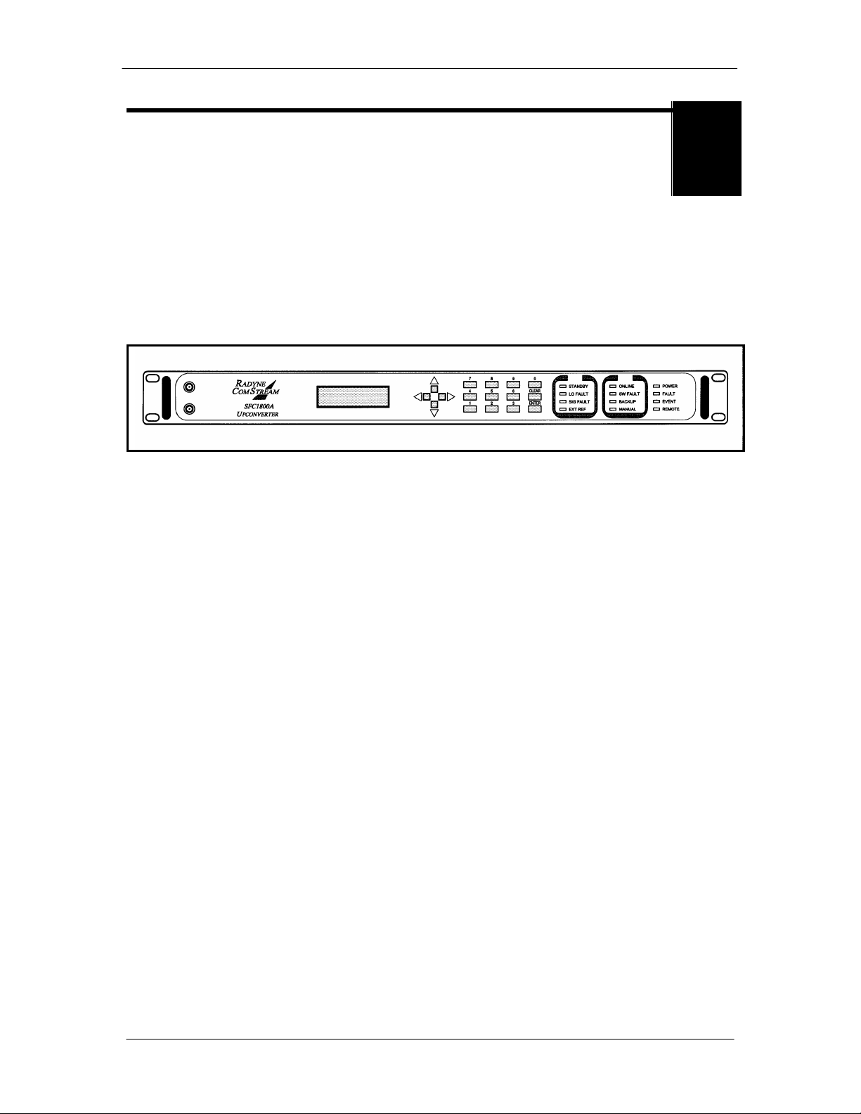
This manual discusses the Radyne SFC1800A Synthesized Frequency Upconverter (Figure 1-1).
This high-qu al ity, rack-mountable sa tellit e upco nverter is intended for use in medi um-to-large
earth station installations where multiple carrier uplinks need to be established . The SFC1800A
Upconverter is ready to be configured into a variety of backup switch configurations, which
include 1:1, and 1:N (where N is a maximum 8) configurations.
Figure 1-1. SFC1800A Upconverter Front Panel
The SFC1800A Upconverter is a DBS-Band, 125 kHz reso lution synthesi zed satellite upconverter
capable of converting either a 3 6 MHz bandwidth, 70 MHz IF inpu t or optionally a 72 MHz
ban dwidth, 140 MHz input to a DBS-Band uplink i n the range of 17.30 - 18.40 GHz.
All of the configu r ation, monitor, an d contr ol functions are available at the front panel. Operat ing
parameters such as frequency, channel, gain, gain offset, and switch settings (backup only) can
be readily set and changed at the front panel. Additionally, all functions can be accessed with a
terminal or personal com puter via a serial li nk (RS-232, RS-485, or Ethernet) for complete remote
monitoring and control ( M &C) capabili ty. Extensive fault monitoring wit h masking capability,
along with time and date stamped event st or age is ava i lable.
The units m onitor l ocal oscillato r ( LO) phase-locked loop faults in the converter at all times dur i ng
operat ion. If a fault i s detected, the converter immediately g oes int o the S tandb y Mode. If
multiple converters are configured t o provide backup protection switching, a summar y fau lt will
sig nal the backup, which will put itself online and r estore the failed circu it.
The RF Hardwar e consists of a broadb and synthesizer, a fi xed freq uency phase l ocked oscillator,
and the first and se cond converter modules. The broadband syn thesizer provides the
synt hesized local oscillator for the conversi on from L-Ban d to RF output. The LO that tunes from
14.80 - 15.9 0 GHz performs this conversion. The second mi xer co nvert s the 70 or 140 MHz IF
input to L-Band. A fixed frequency First IFLO performs this frequency conversion.
A 20 dB gain co ntrol attenu ator at t he L-Band of the second m i x module controls the power out of
the converter. This attenuator is capable of 0. 1 dB reso lution through a software li near
interpolat ion of 1 dB cal i bration values.
TM111 – Rev. 1.0 1-1
Page 14

Introduction SFC1800A Synthesized Frequency Upconverter
The SFC1800A Upconverter have been designed to provide performance that meets or exceeds
all in dustry standards i n effect today for satell i te com muni cation s earth stati on frequency
converter eq uipment fou nd worldwide. In addition to providing robust performance , th e
SFC1800A Upconverter are loaded with feat ures t hat will provide ease of integration and
operation.
1.1 Protection Switch Versatility
Radyne SFC converters featur e ‘plu g-and-play’ ease of installation wit h th e RCU101 1:1 or th e
RCU1 08 1:8 Redundancy Control Units. All convert er s can be plugged in to the b ackup slot and
assume the r ol e of protection switch con troller. The backup converter l earns and stores the
frequ ency, gain and channel settings of the p r imary conver ters. The backup converter can be
operat ed automatically, in which case an automatic backu p of a fault ed, online C onverter occurs
after a user-programmed delay. The Backup may also be operated manually, all owing the user
to m anually switch i n the B ack up Uni t. The Fron t Panel controls and indica tors p r ovide for
automatic/man ual configurat ion, as well as display of onlin e/offline status information. In the
event the stored settings of the Prim ar y Converter are changed, th e backup co nverter will not i fy
the user.
All circu i ts are p r otected upon installation of the swit ch an d completion of the lear ning process.
This eli min ates the need for complicated soft ware configurations that m i ght oth er wise lea ve a
circuit vu l nerabl e. Likewise, rep l acing a failed converter is as sim ple as plugging in a
replacement.
1.2 Chain Switching (Optional)
Chain Switching is availab l e as an op tion for the SFC1800A Upconverter. This unit can be
delivered with t he optional Chai n Switching Module in place, or may be purchased separ ately and
installed by the customer (no tools are required). When equipped with thi s module, in the event
of a unit failure (in a 1:1 or 1:N Configuration where N is less than or eq ual to 8), the upconverters
themselves perform the switching. This elimi nates the need for a separate converter protection
switch such as the Radyne RCU101 or RCU108.
1-2 TM111 - Rev. 1.0
Page 15
SFC1800A Synthesized Frequency Upconverter Installation
Installation
2
2.0 Installation Requirements
The SFC1800A Upconverter is desig ned to be installed within any standard 19 inch eq uipm ent
cabi net or rack, an d requi r es 1 Rack Unit (1RU) mounting space (1.75 inches, 4.44 cm) vertically
and 19 inches (48.26 cm) of depth. Including cabling, a minimum of 20 i nches (50.8 cm ) of rack
dep th is required. The rear panel is has power enter from the left and cab ling en ter from the
center and right as viewed from the rear of the unit. Dat a and con trol cabling can enter from
either side. The unit can be placed on a table or suit able st able surface if requir ed.
Before initially applying power to the unit, it is a good idea to disconnect
the transmit output from the operating station equipment. This is
especially true if the current SFC1800A Upconverter configuration
settings are unknown, where incorrect setting could disrupt existing
comm u nica tions traffi c.
There are no user-serviceable parts or configuration settings located
inside the SFC1800A Upconverter chassis. There is a potential shock
hazard internally at the power supply module. DO NOT open the SFC
Chassis under any circumstances.
The SFC1800A Upconverter contains a Lithium Battery. DANGER OF
EXPLOSION exists if the battery is incorrectly replaced. Replace only
with the same or equivalent type recommended by the manufacturer.
Dispose of used batteries in accordance with local and national
regulations.
TM111 – Rev. 1.0 2-1
Page 16

Installation SFC1800A Synthesized Frequency Upconverter
2.1 Unpacking
The SFC1800A Upconverter was carefull y packag ed to avoid damage and should arrive
complete wit h the followin g items for pr oper in stallation:
SFC1800A Upconverter Unit
Power Cor d, 6 foot with applicable AC Connector ( for North Ameri ca)
Installation and Operation Manual
2.2 Removal and Assembly
The unit is shipped fully asse mbl ed. It does not r equire removal of the covers for any purpose in
installation.
Carefully unpack the un it and ensure that all of the above items ar e in the carton. If avail able AC
mains power available at the installation si te requires a different cord set form the one incl uded in
the packag e, then a suitab l e and approved cordset (for the country where t he equipment is to be
installed) will be required before proceeding with the installation.
Sh ould the Power Cabl e/AC Connector be of the wrong type for the in stallation, either the cable
or th e power connector end should be repl aced. The power su pply itself is desig ned for universal
AC applica tion. See specifications for the appropriate voltages an d cu r r ents.
2.3 Mounting Considerations
When mounted in an equipm ent rack, adequate ventilation must be provided. The ambient
tem perature in the rack should be between 10°C and 35°C, and held co nstant for best equipment
operat ion. Th e ai r available to the r ack should be clean and relati vely dr y.
2.4 Initial Power-Up
Turn the unit ‘ON’ by pl acing th e r ear panel swi tch ( above the power entry connector) to t he ‘ON ’
position. Upon initial and subsequent power-ups, the SFC1800A Upconverter w i ll test itsel f and
several of its components before beginning i ts main Monitor & Control Program. The Event
Buffer LED will illuminate and the unit will log setup events upon power-up. This allows the user
to tel l if there was an accidental power failure or i f the power was manually cycled for any reason
while the unit was left unattended. These events can be cleared after setup. If any failure is
detected, an Alarm LED will illuminate.
2-2 TM111 - Rev. 1.0
Page 17
SFC1800A Synthesized Frequency Upconverter Theory of Operation
Theory of Operation
3
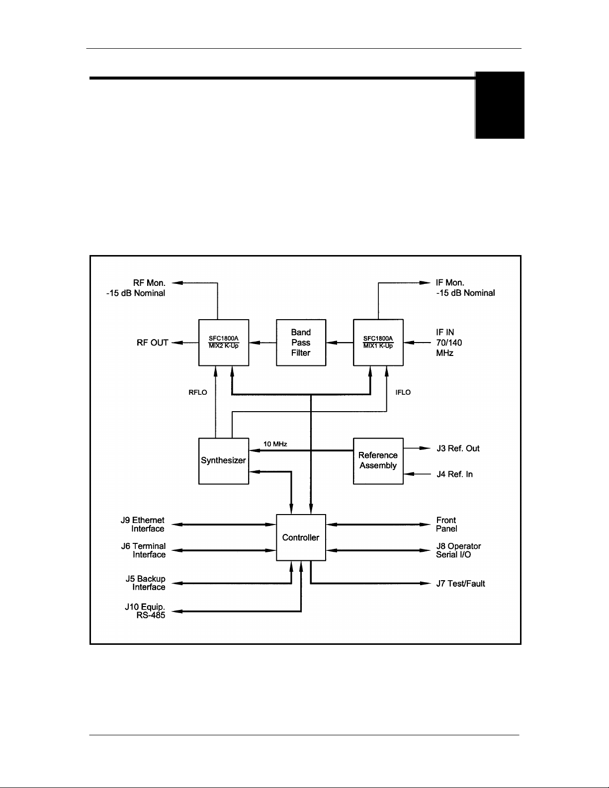
3.0 Theory of Operation
The SFC1800A Upconverter has been desig ned to minim i ze the am ount of hardware in the
system, while maximizin g performance . Spurious per formance in t he upconverter is criti cal and
in particular, LO related spur i ous in-band is nonexistent .
The unit is a double conversion microwave upconverter. Th e basic block diagr am is shown in
Figure 3-1.
Figure 3-1. SFC1800A Upconverter Block Diagram
TM111 – Rev. 1.0 3-1
Page 18
Theory of Operation SFC1800A Synthesized Frequency Upconverter
3.1 Converter Configuration
The SFC1800A Upconverter has three basic operating configurations. These are: S tand-Alone,
1:1 Sw it ch, and 1:8 S witch.
The upconverter automatically detect s the equipm ent to which it is conn ected, and adjusts its
operat ion accor dingly. S ome user menus, most notably the switch Men u, are only avail able if the
up converter i s connected as the backup unit in a Redundancy Switch System.
The Switch Systems may be referred to as either a Redundancy Switch, a
Protection Switch, or simply a Switch. In addition, in all switch
configurations, the Backup Unit acts as the master (it controls all switch
operations).
3.1.1 Stand-Alon e Opera t io n
If J5 on the Back Pan el of the SFC1800A Upcon vert er (B.U. SWI TCH INTERFACE) is n ot
connected to a Switch, th e unit will automatically configu r e i tself for Stan d-Alone Operati on. The
user can set up all configurabl e param eters using one of t he four differen t In terfaces described in
Section 4.
3.1.2 1:1 Switch
In the case of a 1 :1 Switch System, the upconverter detects to which connector on the switch it is
connected (INTERFACE BACKUP or INTERFACE PRIMARY).
The Primary is also sometimes referred to as the Prime.
If the upconverter is conn ected as the backup, then al l the switch con trols are available to t he
user on that unit.
Figure 3-2 illustrates a typical interconn ection of a SFC1800A Upconverter with an RCU101 1:1
Prot ection Switch.
3-2 TM111 - Rev. 1.0
Page 19

SFC1800A Synthesized Frequency Upconverter Theory of Operation
3.1.3 1:8 Switch
In a 1:8 Switch, the Converter detects whet her it is con nected as PRIM ARY1 through
PRI M ARY8, or as the BACKUP. The RCU108 is flexible in that it can be set up with anywhere
from 1 through 8 Pri mary SFC 1800A Upconverters. H ow ever, there is only on e backup. Thus,
only one Prime can be backed up at one time.
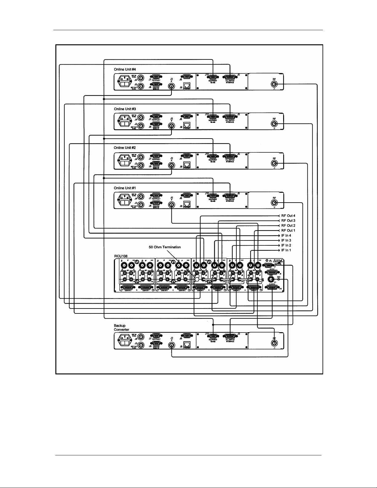
Figure 3-3 illustrates a typical interconn ection of a SFC1800A Upconverter with an RCU108 1:8
Protection Switch. The configuration shown is a 1:2 Switch.
3.2 Optional Chain Switching Operation
For Ch ain Swit ching, each convert er in a 1:N configurat i on (where N is less than or equal to 8)
will co ntain an op tional C hain Switching Module. Duri ng set up, one of the con verters will be
considered the backup. This is u sually th e converter at t he bot tom of th e r ack. Once the system
is set up and proper l y wi r ed, each con verter t hen has an ID Address and can be programmed
from t he Fron t Panel to set the priority level of each converter in the rack. If no priority is set from
the Front Panel then th e priority will default to level one with the converter cl osest to the back up
having the highest prior i ty and priorities incrementall y decreased the furt her from the back up.
Figure 3-2. RCU10 1 Typ ic al In t er co n nectio n w it h S FC 1 800A Upco nverter
TM111 – Rev. 1.0 3-3
Page 20

Theory of Operation SFC1800A Synthesized Frequency Upconverter
After al l of the converters have been programmed, th e back up co nverter is then set into a “Learn
Mode. ” The backup poles each converter on a continuous basis, and learns then stores the
setting s of each con verter. Because the swi tch m odules are on a common pr otection bus, each
converter knows the address (position in th e r ack), and the faul t status of all of the converter s in
the r ack. In the event of multiple fail ures, the highest priorit y co nvert er that fails is backed up fir st.
The chain switch provides the primary through path between the converter RF output and the
output of the switch module without bei ng powered . It i s provided with redundant power from all
converters co nnected in the chai n. In the event that a Upconvert er needs to be replaced, th e
Chain Switching Module ca n be removed from the back of t he converter and left in place with out
breaking the interconnecti ons to adj acent converters in t he ch ai n.
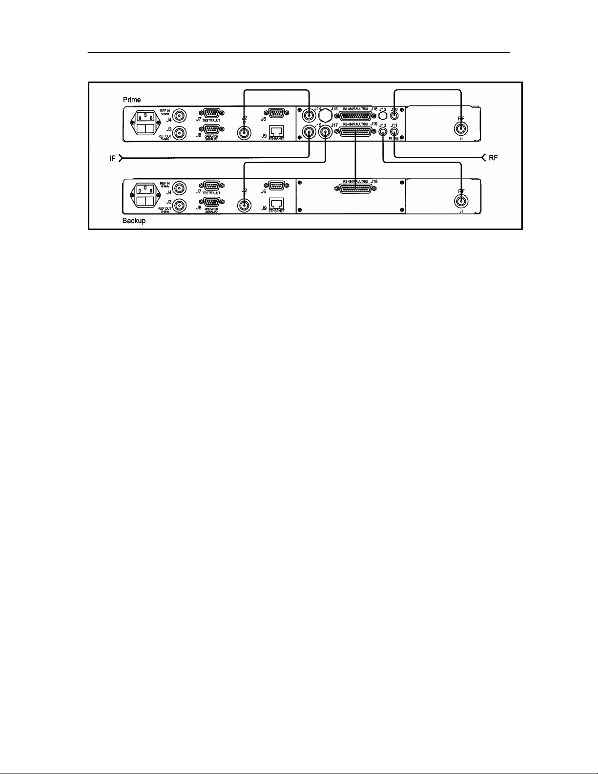
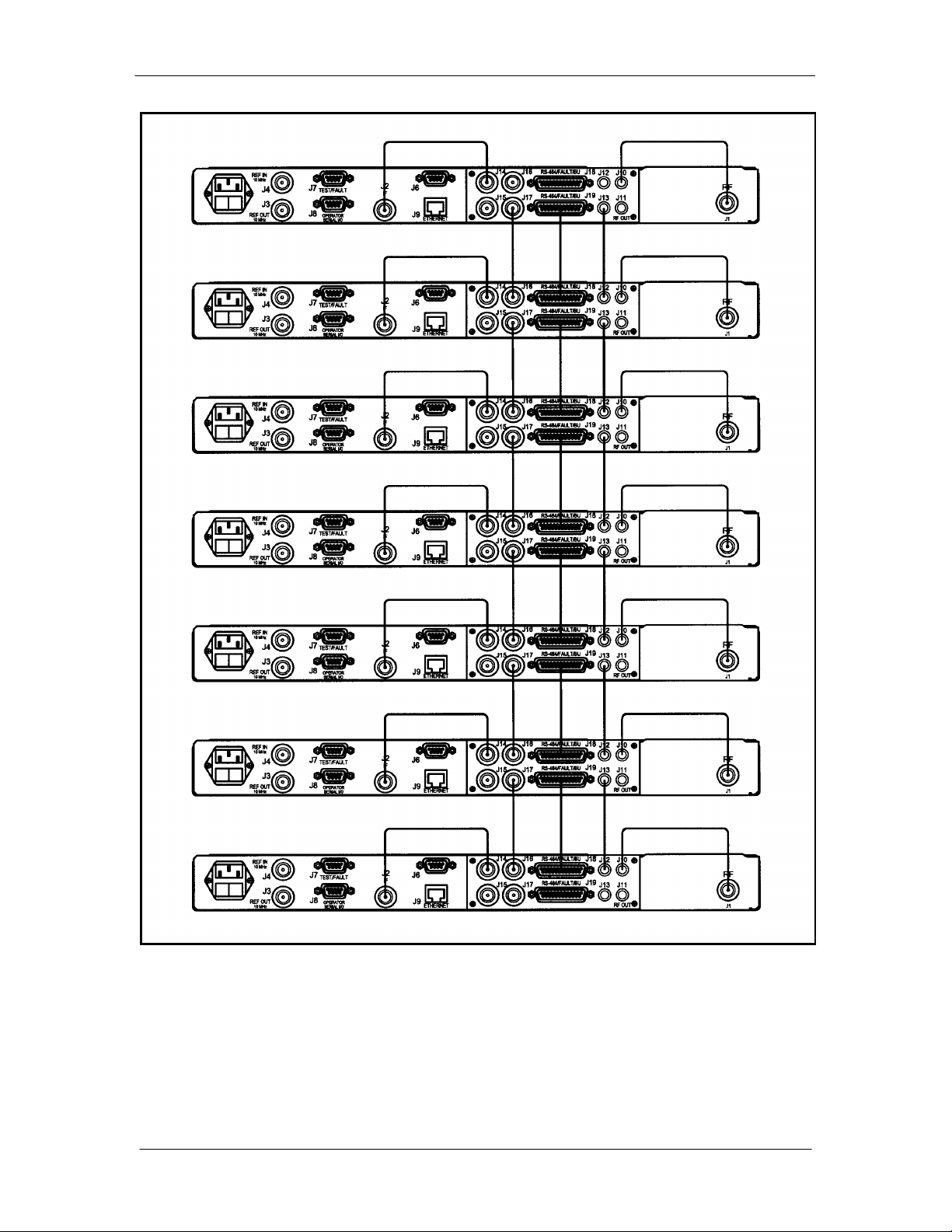
Refer to Figure 3-4 for Chain Switching Operation in a 1:1 configuration, and Figure 3-5 for a 1:N
configuration.
3-4 TM111 - Rev. 1.0
Page 21
SFC1800A Synthesized Frequency Upconverter Theory of Operation
Figure 3-3. RCU108 Typical Interconnection with SFC1800A Upconverter
TM111 – Rev. 1.0 3-5
Page 22
Theory of Operation SFC1800A Synthesized Frequency Upconverter
Figure 3-4. Chain Switching Operation in a 1:1 Configuration
3-6 TM111 - Rev. 1.0
Page 23
SFC1800A Synthesized Frequency Upconverter Theory of Operation
Figure 3-5. Chain Switching Operation in a 1:N Configuration.
TM111 – Rev. 1.0 3-7
Page 24

Theory of Operation SFC1800A Synthesized Frequency Upconverter
3-8 TM111 - Rev. 1.0
Page 25
SFC1800A Synthesized Frequency Upconverter User Interfaces
User Interfaces
4
4.0 User Interfaces
There ar e four User Interfaces avai l able for the S FC1800A Upconverter. These are:
Front Pan el
Remote Port
Term i nal Port
Ethernet Port
4.1 Front Panel User Interface
The Fron t Panel of the SFC1 800A Upconverter allow f or complete monit or and control (including
bu t not limited to operation, cali bration, and testing) of al l param eters and functions via Monit or i ng
Ports, a Keypad, LCD Display and Status LEDs.
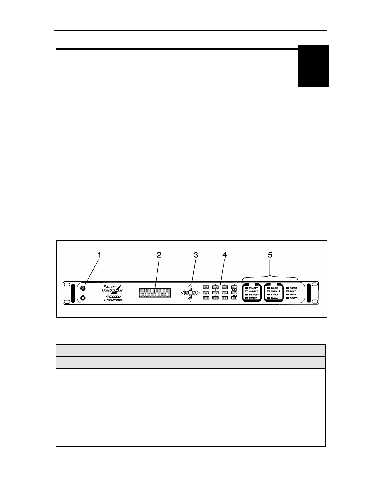
The front panel layout is shown in Figure 4-1, sh owing th e l ocation and l abeling of the front panel.
The front panel is divided into fou r functional ar eas: Mon itoring Ports, LC D Displ ay, Cursor
Control Arrows, Numeric Keypad, and LED Indicators. Each is described below. Tabl e 4-1 lists
each of these areas. Th ey are fu r ther described below.
Figure 4-1. SFC1800A Upconverter Front Panel Controls and Indicators
Table 4-1. Front Panel User Interface
Item No. Description Function
1 Monitoring Port s Allow monitoring of the RF an d IF Signals.
2 LCD Display Displays SFC 1800A Upconverter operating
parameters and configuration data.
3 Cursor Control Arrows Controls the left, r i ght, up, and down motion of t he
cursor in the LCD Display window.
4 Numeric Keypad Allows entry of numeric d ata and Clear and Enter
Function Keys.
5 LED Indicators Displays SFC1800A Upconverter operating status.
TM111 – Rev. 1.0 4-1
Page 26

User Interfaces SFC1800A Synthesized Frequency Upconverter
→
The Left/Right Arrow Keys are used to move through the Menu structure. The
↑
4.1.1 Monitorin g P orts
Refer to Sect ion 5.12.
4.1.2 LCD Display
The front panel display is a 2 line by 16-character LCD display. The display is lighted and the
brightn ess can b e set to in crease when the front panel is currently in use. The LCD display
automatically dims after a period of inactivity. The display has two distinct fields showing current
information. The upper field shows the current parameter b eing m onitored, such as
'FREQUENCY (GHz)' or 'CHNL G AIN (dB)' . The lower field shows the curr ent value of that
parameter. Th e LCD displ ay is a single entry window into the large matrix of para meters that can
be monit or ed and se t from the front panel.
4.1.3 Cursor Control Arrows
Table 4-2. Cursor Control Arrow Keys
Key Function
Left/Right
Arrow Keys
(
), (←)
Left/Right Arrow Keys are al so used to m ove the cursor to a specifi c digit in a
number field. No changes i n the values or status can be execu ted from the
left/r i ght cursor movem ent.
Up/Down
Arrow Keys
(
), (↓)
The Down Arrow K ey is used to move from a Menu screen to the selections or
submenus b eneath that Menu. The Up Arrow does the reverse, moving from a
submenu or selection to a higher-level Menu.
The Up/Down Ar r ow Keys ar e also used to change the value of some
parameters. Some Menu items, su ch as SYSTEM<CON TROL MO D E, contain
a list of possible set tings. The Ar r ow K eys are used to scroll through the list
until the desired settin g is displayed. Similarly, these keys togg l e the ± si gn of
any signed param eters. <ENTER> is then u sed to execute th e selecti on.
For numerical parameters, such as CONVERTER<FREQ UE N CY(GHz), the
Arrow Keys can be use d to scrol l through th e possi ble values of each
part icular digit. The Left/Right Keys ar e used to move the cursor to th e desired
digit. To execute a change, <ENTER> must be pressed.
4-2 TM111 - Rev. 1.0
Page 27

SFC1800A Synthesized Frequency Upconverter User Interfaces
4.1.4 Front Panel Keypad
The front panel keyp ad consists of two areas: a 10 -ke y numeric en try with 2 addit ional keys for
the ‘Enter’ and ‘C lear’ fun ction. The second ar ea i s a set of ‘Arrow’ or ‘Cur sor’ ke ys (
(
←), used to navigate the p ar ameter currently bei ng moni tored or co ntrolled. Tab le 4-3 describes
the key functions available at the front panel .
Table 4-3. Front Panel Keypad
Key Function
0 to 9 The Number Keys are used to change numeric values in the value field of the
LCD display.
CLEAR If pressed before <ENTER> d urin g a param eter change, t he CLEAR Key will
cause that par ameter to return to its original value.
ENTER The E nter Key will cause changes to Frequency, Status, and other operator-
selected par ameters to be executed. It also causes the status of the co nverter
to be saved into non-volatile mem or y.
↑), (↓), (→),
4.1.5 LED Indicators
There ar e twelve (12) LE D s on the SF C1800A Up converter Front Panel to indicate the operation
status (refer to Tabl e 4-3).
Table 4-3. Front Panel LED Indicators
LED Color Function
POWER Green When illum inated, indicates the presence of prim ar y power
and that the On/Off S witch located on the rear of the chassis
is in the On Position .
FAULT Red When illum inated, Indi cates a co m mon fault (internal
hardware).
EVENT Yellow When illumin ated, indicates that an event (may be a faul t or
startup sequence) has occurred and is stored i n the Event
Bu ffer along with a date/time st am p.
REMOTE Green When illum inated, indicates that th e converter is in R emote
Mode. In this mode, the unit settings can only be modified
and contr ol led via a remote in terface.
ONLINE Green W hen illuminated, indicates that the backup converter has
been placed online to backu p a Prime Converter ( backup
converter Only).
SW FAUL T Red When illum inated, indicates that an error has occurred dur i ng
a Backup Process. (backup converter Only). If a SW Fault
does not exist but a Learned or a Backup Test Fault exists,
this LED will flash at one-second intervals.
BACKUP Yellow Not use d.
MANUAL Yellow When illum inated, indicates that th e backup converter has
been Manually placed Online (backup converter Only).
TM111 – Rev. 1.0 4-3
Page 28

User Interfaces SFC1800A Synthesized Frequency Upconverter
STANDBY Green When il luminated, indicates th at the converter h as been taken
offline and backed up by the Backup (Converter Prime
Converter in a 1:1 or 1:N Switch Only).
LO FAULT Red If the Synthesized LO or IFLO System of the converter
indicates an out-of-lock condition, th e LO Fau lt LED will
illu min ate. At this time, the Summary Fault Relay Contacts
will latch. If the LO Fault was du e to an Inter mittent Fault
Condition, the LO Fault will flash at one-seco nd intervals, and
fault checked may b e r eset.
SIG FAULT Yellow S ignal Fault s are used in switch configuration t o indicate
switch status (when in the Backup Mode).
EXT REF Yellow This LED i l luminates when an external 10 MHz reference
sig nal has been applied to the converter. A LO fault may
occur when t he extern al refer ence is applied or removed.
This indicates t hat a change in the reference has occurr ed.
This fau lt can be clear ed with a soft reset.
4.2 Front Panel Control Screen Menus
The complet e set of SFC1800A Upconverter Front Panel C ontrol Screen s are contained within
the following Main Menus:
4.2.1 Main Menus
Converter Menu Options and Parameters
Switch Menu Options and Parame ters
Monitor Menu Options and Parameters
Alarms Menu Options and Parameters
System Menu Options and Parameters
Test Menu Options and Parameters
4-4 TM111 - Rev. 1.0
Page 29

SFC1800A Synthesized Frequency Upconverter User Interfaces
4.2.2 Converter Menu Options and Parameters
FREQUENCY (GHz): {17.30 – 18 .40 GHz}
Sets the RF output frequency.
CHNL GAIN (dB): {-20.0 to +30.0, dependent upon input attenuation}
Sets the Cha n ne l Gai n in 0. 1 dB st e ps.
CARRIER CNTRL: {ON, OFF}
Allows the u ser to turn the carrier on/off.
INPUT ATTEN: {0 - 30}
Sets the input attenuation in 1 dB steps.
CURRENT CHNNL: {01 – 30}
Selects the current channel of the unit. Each channel
allows enter i ng of an ind ependent set of param eters
(Freq uency, Gain , etc.). For example, Chann el 1
Frequency might be set to 5.9 GHz and Channel 2 could
be set to 6.0 GHz. Any of the oth er parameters could be
differ ent as well. The advantage is that by chan ging the
channel number, a co mpletely diff er ent setup can be
achieved.
4.2.3 Switch Menu Options and Parameters
This Menu is only available when the upconverter is conn ected i n a 1:1 or 1:N Switch
configuration as the Backup Unit.
BACKUP MODE: {MANUAL, AUTO-NONREVE, AUTO-REVERTI}
Sets the Backup Mode of the swi tch.
Manual: A Prime Con verter can be backed up t hrough
manual control onl y.
Auto-Nonrevertive: A Prime C onverter will be backed
up if it fails. It will remain backed up until it is manually
unbacked.
Auto-Revertive: A P r i me Con verter will be backed up i f
it fails. If a second Converter, which has been deemed
higher prior i ty (see Monitor Backup S tate below) fails,
the switch will unback the first and backup the second
Converter. If the first Con verter recovers after it has
been backed up (i.e., no l onger has a fault) , and a
second Con verter fails, the recovered unit will be put
back on line and the new faulted unit will be backed up.
FORCE BACKUP <SELECT PRIME >: {PRIME 1 - 8, UNBACK}
When i n Manual Backup Mode, this selection will force
the selected Prime to be backed up. Unback will release
any Prime that is currently backed up.
TM111 – Rev. 1.0 4-5
Page 30

User Interfaces SFC1800A Synthesized Frequency Upconverter
LEARN <SELECT PRIME>: {PRIME 1 - 8, ALL}
Cause s the Backup Unit to "Learn" all the sett ings of the
selected Pr imes. The Backup Upco nverter can only
backup a Prime that it has l ear ned. A backup test i s
performed as the unit is learned.
FAULT DELAY: {00050 - 10000}
Sets the del ay between the t ime a Fault occurs in a
Prime Uni t and th e time it is acknowledged by the
Backup. The unit is Milliseconds (ms).
COMPENSATION: {ENABLE, DISABLE}
Enables or disabl es the Compensation control descri bed
in Prime Setup below.
PRIME SETUP:
PRIME #:
PRIORITY: {0 - 8}
Sets the switching priority of a Prime Un it. If more than
one u nit fail s at the same ti me, the higher priorit y unit will
be backed up. Also, if one unit is currently backed up
and a second unit with a higher priority fails, the first unit
will be unbacked and the second unit will be backed up
(but only if Backup Mode is Auto-Revertive, see Backup
Mode above). The priority is se t as fol l ows:
0 = No p r iority (the switch will ignore the upconverter). If
at any time a Prime’ s priority is set t o 0, t he
Backup will p urge any learned parameters of
that Prime.
1 = Highest priority.
8 = Lowest prior i ty.
COMPENSATION: {- 5.0 - +5.0}
Offsets the gain of the Backup Uni t to account for
variations in loss through the system. This allows the
user to ensure that the signal path of a particu lar Prime
Converter maintain s the same outp ut power wh en
backed up.
MONITOR:
BACKUP STAT E: {NONE, PRIME1 - 8}
Reports the current Backup Stat e of the swit ch. If no
Prime is backed up , then the state is reported as
<NONE>. If a unit is currently backed up, then its
number is reported.
4-6 TM111 - Rev. 1.0
Page 31

SFC1800A Synthesized Frequency Upconverter User Interfaces
HOTSTBY STATE: {NONE, PRIME1 - 8}
Displays the number of the unit that is currently in Hot
Standby. H ot Standby is on l y active when th e swi tch
Mode is set t o Auto (Revertive or Nonr evertive). In this
condition, the Prime Converter with the highest assigned
priority is p ut in Hot St andby.
PRIME #:
SUMMARY F AULT: {P ASS, FAIL}
Reports the sy stem fault status. This is t he summary of
all the Major, M i nor, and Common Alarms cur r ently
present in all the i ndividual Prime Converters.
LEARNED: {YES, NO}
Reports whether the Prime has been learn ed by the
Backup.
BACKUP TEST: {P ASS, FAIL}
Reports whether the Prime has passed the Backu p Test.
CONFIG CHANGED: {YES, NO}
Reports whether the Prime confi guration has chang ed
sin ce being learned by the Backu p.
RELAY STATUS : {ON, OFF }
Displays th e status of the Prime U nit's cor r espon ding R F
Relay in the switch Unit. 'On' indicates that the Prime is
being ba cked up.
4.2.4 Monitor M enu Opt io ns an d Para me ter s
REFERENCE: {INTERNAL, EXTERNAL}
Indicates th e r eference source of the u nit. The
SFC1800A Upconverter will detect a valid external
reference so urce when it is connected to J4 on th e r ear
pan el and automat i cally select 'External' . Like wise,
when no signal (or a signal not meeting the Refer ence
input specification) is co nnected t o J4, the unit will swi tch
to the 'Int er nal'. The process is compl etely automatic,
and i t is independ ent of M&C co ntrol.
MON VOLTAGES:
RF DETE CTOR V: Monitors the voltage of th e RF Detector.
IF DETECTOR V: Monitors the voltage of th e IF Detector.
DAC ATTEN V: Monitors the voltage of th e Outp ut Attenuator DAC.
VCC1 VOLTAGE: Displays the voltage of th e C ontroller P C B
Microprocessor +5V.
+9V VOLTAGE: Displays th e voltage of the System Supply +9V.
TM111 – Rev. 1.0 4-7
Page 32

User Interfaces SFC1800A Synthesized Frequency Upconverter
+15V VOLTAGE: Displays th e voltage of the System Supply +15V.
- 15V VOLTAGE: Displays the voltag e of the System Supp ly -15V.
M ON DACS:
MIXE R DAC VAL: Displays the decimal value written to the RF Attenuation
DAC. This value is not under user control.
MIXE R DAC VOL: Displays th e expected voltage out put of the RF
Attenuat i on DAC .
REF DAC VALUE: Displays the decimal value written t o the VCO Reference
Control DAC . This value is entered by the user in t he
TEST\REF O FFSET Menu, and cannot be changed from
this Menu.
REFDAC VOLTAGE: D i splays the expected vo l tage output of the VCO
Reference Control DA C.
EVENT BUFF The Event Buffer stores any faults that occur, including
start up p r ocedu r es, alon g with a ti me/date stamp.
PRESS CLR TO
ERASE EVENTS: Pressing the <CLEAR> when this screen is displayed
will erase all of the events currently stored in the E vent
Buffer.
4.2.5 Al arms Menu Optio ns an d Par a meters
For the alarm s list ed below, the P ASS/FAIL displayed is only an indica tor and cannot be changed
by the user. The MASK/UNMASKED Field, however, does al low user input. M asking an al ar m
will cause it to be ignored by the unit if that alarm fails. The LCD will display FAIL, bu t the unit will
other wise not respond to the Fau lt. This function can ai d in tr oubleshootin g system problems.
ACTIVE ALRMS:
MAJOR:
LO FAULT: {PASS, FAIL/UNMASKED, MASKED}
Reports an alar m when the Synthesi zer Module
indicates an unlocked condition.
SIGNAL FAULT: {PASS, FAIL/UNMASKED, MASKED}
Reports a fail ure wh en there is an IF Detect Fault.
BACKUP FAULT: {PASS, FAIL/UNMASKED, MASKED}
backup converter only. Indicates th at a Backup process
has fail ed.
NO BACKUP: {PASS, FAIL/UNMASKED, MASKED}
backup converter only. Indicates th at a Faul ted Prim e
could not be backed up.
4-8 TM111 - Rev. 1.0
Page 33

SFC1800A Synthesized Frequency Upconverter User Interfaces
POLLING FAULT: {PASS, FAIL/UNMASKED, MASKED}
backup converter only. Indicates th at an interconverter
comm unication failure has occurr ed.
RELAY FAULT: {PASS, FAIL/UNMASKED, MASKED}
backup converter only. Indicates th at the RF Relay used
to switch in the backup is not in its expected state.
MINOR:
LEARNED FAULT: {PASS, FAIL/UNMASKED, MASKED}
backup converter only. Indicates th at the B ackup cou ld
not learn the settings of one or mor e Prim e Converters.
The SW Fault will flash at one-second int er vals to flag
this fault to the user.
BKP TEST FAULT: {PASS, FAIL/UNMASKED, MASKED}
backup converter only. Indicates th at the B ackup has
deter min ed, by use of the Backup Test, th at it will not be
able to backup one or more Pr i me Con verters. Th e
Backup Test is don e wh en the <LEARN> function is
initiated. The SW Fau lt will flash at one-seco nd intervals
to flag this fault t o the user .
CFG CHGD FAULT: {PASS, FAIL/UNMASKED, MASKED}
backup converter only. Indicates th at the configuration
of one or more Pr i me Con verters has changed since
being learned by the Backu p. Note that the Backu p
continuously monitors the settings of all Prime Un i ts in
the sy stem to determine if anything changes. The SW
Fault will flash at one-second intervals to flag thi s fault to
the user.
RF DTECT FAULT: {PASS, FAIL/UNMASKED, MASKED}
Indicat es a failure wh en the detected R F input signal
falls below a fixed threshold.
IF DTECT FAULT: {PASS, FAIL/UNMASKED, MASKED}
Indicat es a failure wh en the detected IF signal falls
below a fixed threshold.
COMMON:
CPLD FAULT: {PASS, FAIL/UNMASKED, MASKED}
Indicat es a fault i f the Controller PCB Mi croproce ssor
reads back an unexpected value from the CPLD. This is
a check performed on system power up.
F PGA FAULT: {PASS, FAIL/UNMASKED, MASKED}
Indicat es a fault i f the Controller PCB mi croproce ssor
reads back an unexpected value from the FPGA. Thi s is
also a check performed on system power up.
TM111 – Rev. 1.0 4-9
Page 34

User Interfaces SFC1800A Synthesized Frequency Upconverter
EEPROM FAULT: {PASS, FAIL/UNMASKED, MASKED}
Indicat es a fault i f the Controller PCB mi croproce ssor
reads back an unexpected value from the EEPROM.
This is checked on system power-up, but is al so
monitored during normal operation.
REFERE NCE ACT: {PASS, FAIL/UNMASKED, MASKED}
A failure indicates that there is no signal connected to
the External Reference input on the back panel. In this
condition, the Converter uses t he internal r eference
oscillator.
VCC1 FAULT: {PASS, FAIL/UNMASKED, MASKED}
Indicat es a fault i f the +5V Suppl y Voltage of the
Controller PC B Microprocessor is outside a fixed range.
+9V FAULT: {PASS, FAIL/UNMASKED, MASKED}
Indicat es a fault i f the +9V System Supply V oltage i s
outside a fixe d range.
+15V FAULT: {PASS, FAIL/UNMASKED, MASKED}
Indicat es a fault if the +15V Syst em Supply Volt age is
outside a fixe d range.
- 15V FAULT: {PASS, FAIL/UNMASKED, MASKED}
Indicat es a fault i f the -15V system supply voltage is
outside a fixe d range.
LATCHED ALRM: The Latched Alarm M enu structur e is identical to the
Active Alarms. However, if any alarm is t riggered it will
be L atched. For example, if an External Reference is
disconn ected from the rear panel, an LO Fault will be
reported while the LO reg ai ns lock. After the LO
recovers, eve n though the Active Alarm no longer
reports the alarm, the Latched Alarm will still disp l ay
<FAIL>. In other words, the alarm was l atched.
CLEAR ALARMS
(ENT = Y,CLR = N): Pressing <ENTER> will clear all of the Lat ched Alarms
curr ently stored.
4.2.6 System Menu Options and Parameters
CONTROL MODE: {FT PANEL, TERMINAL, COMPUTER, ETHERNET}
Sets the Control Mode of the upcon verter.
DATE: Allows the u ser to enter the date i n DD/MM/YY format.
TIME: Allows the use r to ent er the t ime in HH :MM:SS format.
FRONT PANEL:
LEVEL: {OFF, LOW, MID, HIGH}
Allows the u ser to set the backlig ht intensity of the LCD
display.
4-10 TM111 - Rev. 1.0
Page 35

SFC1800A Synthesized Frequency Upconverter User Interfaces
TIMEOUT: {00 - 99}
Allows the u ser to set the l ength of inactive t i me (in
seconds) after which the display backlight shuts off
automatically. E ntering 00 all ows the b acklight to remain
on continuously.
KEY CLICK: {OFF, ON}
Allows the use r turn an aud ib le key click on/off.
TERMINAL:
TERM. BAUD: {2400 , 9600, 192 00}
A l lows the user to set the baud r ate for terminal port
communication.
EMULATION: {ADDS VP, VT100, WYS E 50}
A l lows the user to set the terminal em ulation mode.
ECHO MODE: {OFF, ON}
A l lows the user to contr ol wh ether the input at the
terminal i s echoed back.
REMOTE POR T:
REMOT E PRT OCOL: {ASCII, RLLP}
A l lows the user to set the remote port communication
protocol.
REM OTE ADDR: {32 - 255 RLLP, 1 – 255 ASCII}
A l lows the user to set the commu nication add r ess of the
remote port .
REM OTE BAUD: {2400 , 9600, 192 00}
A l lows the user to set the baud r ate for remote port
communication.
ECHO MODE: {OFF, ON}
A l lows the user to contr ol wh ether the input at the
terminal i s echoed back. Only valid in Remote AS C II
Mode.
REMOTE LINE: {RS-232, RS-485}
S ets the interface type of the remote por t.
HW/FW CONFIG:
FIRMWARE: FW/XXXX - - Version Y.YY
Displays the re vision numb er of the install ed M&C
Firmware (wh er e XXXX is the firmware num ber and
Y.YY is the version).
FW/XXXX - - 19DEC2002
Displays the re vision numb er and release date o f the
installed M&C Firmware.
TM111 – Rev. 1.0 4-11
Page 36

User Interfaces SFC1800A Synthesized Frequency Upconverter
CPLD VERSION: {x.x}
Displays version number of installed CPLD Firmware.
FPGA VERSION: {x.x}
Displays version number of installed FPGA firmware.
HARDWARE:
CONVRTR CONFIG: {STAND ALONE, PRIMARY 1F1, BACKUP 1F1,
PRIMARY 1 - 8 1F8 , BACKUP 1F8}
A l lows the user to i ndicate the function of the Converter
as it i s connected in the system. The M &C determines
this by reading 4 ID bits through the switch interface
(refer to Section 5 .10).
CONVERTER ID: {1 - 11, 15}
Disp lays a decim al version of the binary ID bits
described above and in Section 5.10. The individual bits
are strapped high or low at the switch. They are
decoded as follows.
Decimal ID Converter Function System Type
0 Not Use d Not Use d
1 Primary 1 1F8
2 Primary 2 1F8
3 Primary 3 1F8
4 Primary 4 1F8
5 Primary 5 1F8
6 Primary 6 1F8
7 Primary 7 1F8
8 Primary 8 1F8
9 Backup 1F8
10 Backup 1F1
11 Primary 1F1
12 – 14 Not Use d Not Use d
15 Stand Alone (ID Bits
Stand Alone
pulle d up on
Controller Card)
CONVERTER TYPE: {DN CONVERTER, UPCONVERTER}
Indicates whether t he unit is an Upco nverter or a
Upco nverter. This display will match the text on the
Front Pan el Overlay.
4-12 TM111 - Rev. 1.0
Page 37

SFC1800A Synthesized Frequency Upconverter User Interfaces
CONVERTER BAND: {C-BAND, KU-BAND}
Indicates whether the unit is a C-Band or Ku-Band
Converter. This disp lay will match the text on the Front
Pan el Overlay.
FREQUENCY TYPE: {70 MHz, 14 0 MH z}
Indicates th e IF type of the Conve r ter.
SYNTHESIZER: {MFS-1191, MFS-44 8, MFS-459, MFS-544, MFS-881,
MFS-474, MF S-4.47 , MF S-4.59}
Displays the m odel num ber of the unit ' s installed
synt hesizer . The frequency range of each model is
given below:
Model IF LO
Frequency
Frequency Range
Low High
MFS 1191 1.7 GHz 11.91GHz 12.73 GHz
MFS 448 1.225 GH z 4.48 GHz 5.355 GHz
MFS 459 1.112 5 GH z 4.5925 GH z 5.2425 GH z
MFS 544 1.112 5 GH z 5.4475 GHz 5.867 5 GH z
MFS 881 2 .0 GHz 8.81 GHz 10.68 GHz
MFS 474 1.112 5 GH z 4.74 GHz 5.54 GHz
MFS 4_47 1.1125 GH z 4.47 GHz 5.34 GHz
MFS 4_59 1.1125 GH z 4.59 GHz 5.54 GHz
DEBUG MODE: Password protected. Enables addition al M enus for
debugging purposes.
LOAD DEFAULT: Password protected. Configures the Converter with a
set of default parameters. Refer to Section 4.5 for act ual
default settings.
SNMP DEFAULT: Password protected. Config ures t he Converter SNMP
(Et hernet Interface ) setti ngs to default values.
TM111 – Rev. 1.0 4-13
Page 38

User Interfaces SFC1800A Synthesized Frequency Upconverter
4.2.7 Test Menu Options and Parameters
REF OFFSET: {0000 - 4095}
The REF OFFSET field of the Test Menu allows the
operat or to adjust the freq uency of t he 10 MHz High
Stability Inter nal Reference and vary t he output of the
Synthesized RF LO by ± 999 parts pe r bill i o n (pp b) . One
part per bi l lion represents a change of 1 H z per GHz ( 1
billion Hz) of output frequency. Thus, each unit of ppb
will allow a change in accuracy of the con verter of
-9
1 x 10
The exact frequency of the LO Output can be calculated
from t he displayed frequency on t he converter front
pan el as follows:
.
C-Band Upconverter
(70 MHz IF)
LO = Tx Freq. - 1 182.5 MHz
C-Band Upconverter
LO = Tx Freq. - 1 252.5 MHz
(140 MHz IF)
C-Band Upconverter
LO = Tx Freq. - 1182.5 MHz
Extended (70 MHz IF)
C-Band Upconverter
LO = Tx Freq. - 1 365.0 MHz
Extended ( 140 MHz IF)
Ku-Band Up converter
LO = Tx Freq. – 1770.0 MHz
(70 MHz IF)
Ku-Band Up converter
LO = Tx Freq. – 1840.0 MHz
(140 MHz IF)
The RF Monitor output can be measured wi th a
frequency counter of known calibration.
The stability of th e 10 MHz Reference i s related to the
tem perature of a 10 M Hz cryst al insi de the unit. A
proportionally controll ed oven around th e crystal
maintains the t em perature in the oven to 0.1°C. In
add i tion, the preci se tem perature th at the oven
maintains has b een determined empirica l ly for each
crystal during manufacturing. As long as the ambient
tem perature stays within limi ts (0 - 50°C) the refer ence
will maintain stability of greater than 1 x 10
-8
(refer to
Figure 4-2).
4-14 TM111 - Rev. 1.0
Page 39

SFC1800A Synthesized Frequency Upconverter User Interfaces
Figure 4-2. Typical Reference Aging vs. Time
Long-term stability of the reference is affected b y factors
other than temper ature. Over days and months, the
frequ ency of t he reference will dr ift at a rate specified as
aging. Typical aging rates of 1 to 5 parts in 10
-10
per day
are typi cal in a crystal that has been stabilized for a fe w
weeks. The first m onth of oper ation for any crystal is a
time where drift due to agi ng can be excessive.
The typical aging curve provides insight into the
exponential decay in aging rate for a 10 M Hz Reference.
Converters shipped from the factory have had their
reference oscillat or aged for a minim um of 30 days and
in addit ion, the aging rate has been verified in the final
week to w ithi n tolerance. H ow ever, converter s that have
been i n storag e or power ed off for a period of several
weeks will exhibit a phenomenon whereby the aging
curve return to the slope shown for zero days of aging.
This aging reset in not well understood but the
manufactu r er s of crystals b el ieve it to b e r el ated t o a
gradual relaxation of th e molecular m akeup of the quart z
substrates and the conductive films deposited on the
quartz.
The rule of thumb when checking the frequency
accuracy of the converter is to make sure that the crystal
has stabilized before att empting any adjustment. For
un i ts that have been in stor age or shipment for more
than a week, allow several d ays of operation before
verif ying the accuracy. F or this r eason, converters
shi pped from Radyne are typically po we r ed-up until the
final day before shipm ent. In addition, the accuracy an d
aging rat e ar e verified immedi ately prior to shipmen t.
TM111 – Rev. 1.0 4-15
Page 40

User Interfaces SFC1800A Synthesized Frequency Upconverter
←→
CONVERTER
For a converter that has b een powered -up for several
months, the operator can assume an aging rate of
several ppb per month. If the aging rate has been
established, the station op er ator can make calculated
adjustments from the reference offset Menu at timed
intervals.
LED TEST: {OFF, ON}
Allows the use r to test the function of all front panel
LEDs. All of the LEDs will cycle on and off except the
Power LED, which is always lit when power is on.
4.3 Examples: Changing Parameters from the Front Panel
4.3.1 Changing Frequency: Numeric Keypad
For this example, it is assumed that the Frequency is currently set to
17.30 GHz.
1. Upon powering up, the Init i alizin g Screen can b e seen on the Front Panel LC D Display
for several second s. This screen indicates the curren t revision of firmware. Next
displayed is one of the following Boot Up Screens.
2. Press and release the Right Arrow Key once. Th e CONVERTER Menu is displayed.
3. Press and release the Left A r r ow K ey six (6) times. N otice th at the Menu field "wrap s"
around and ends up at the CO NV ERTER screen again.
4. Press and release the Down Arrow K ey. The FR EQUENCY (GHz) Scr een is displayed.
SFC1800A
DBS-BAND UP
↓
(menu) ←→
4-16 TM111 - Rev. 1.0
Page 41

SFC1800A Synthesized Frequency Upconverter User Interfaces
FREQUENCY(GHz)
5. Press and release <ENTER> once. The cu r sor appears at the lo wer left corner of the
LCD Display.
6. Press and release the Right Arrow Key unt il the cursor is at the d ig it to the right of the
deci mal point. Press and release <9> on the numeric Keypad. The “9” dig it now appears
at that position and th e cursor moves one location to the r ight.
7. Press and release <ENTER> once. The cu r sor is n o longer visible, and the frequency
field now displays "17.900000".
17.300000 ←→
FREQUENCY(GHz) ↓
17.900000 ←→
↓
4.3.2 Changing Frequency: Up/Down Arrow Keys
1. Upon powering up, the Boot-Up Screen is shown in the LCD display.
2. Press and release the Right Arrow Key once. Th e CONVERTER Menu is displayed.
3. Press and release the Down Arrow Key. Th e FREQ U ENCY (G H z) Scr een is displayed.
4. Press and release <ENTER> once. The cu r sor appears at the lo wer left corner of the
LCD display.
5. Press and release the Right Arrow Key unt il the cursor is at the d ig it to the right of the
decimal point. Press the Down Arrow Key until the display shows "17.900000". The
cursor is still visible and flashing over the number "3", to the right of the decimal point.
7. Press and release <ENTER> once. The cu r sor is n o longer visible, and the frequency
field now displays "17.300000".
8. Press and release <ENTER> once. The cu r sor appears at the lo wer left corner of the
LCD Display.
FREQUENCY(GHz) ↓
17.300000 ←→
4.3.3 Changing Control Mode to 'TERMINAL'
TM111 – Rev. 1.0 4-17
Page 42

User Interfaces SFC1800A Synthesized Frequency Upconverter
CONTR OL MODE
1. Upon powering up, the Boot-Up Screen is shown in the LC D dis pl a y.
2. Continue pressing and releasing the Left Arrow Key until the SYSTEM Menu is displayed.
3. Press and release the Down Arrow Key. The CONTROL MODE screen is displayed.
4. Press and release <ENTER> once. The cu r sor appears at the lo wer left corner of the
LCD Display.
5. Press and release the Up Ar r ow K ey unti l the bot tom fiel d displays "TERMINAL".
6. Press and release <ENTER> once. The cu r sor is n o longer visible, and the sel ection has
now been changed t o "TERMIN AL".
CONTR OL MODE ↑
COMPUTER ←→
↑
TERMINAL ←→
4.3.4 Changing Control Mode Back to 'FT PANEL'
1. Upon powering up, the Boot-Up Screen is shown in the LCD display.
2. Press and release the Right Arrow Key unt il the SYSTEM Men u i s disp l ayed.
3. Press and release the Down Arrow Key. Th e CONTROL MODE Screen is displayed.
4. Press and release <ENTER> once. The cu r sor appears at the lo wer left corner of the
LCD Display.
5. Press and release the Up Ar r ow K ey unti l the bot tom fiel d displays "FT PANEL".
6. Press and release <ENTER> once. The cu r sor is n o longer visible, and the sel ection has
now been changed to "FT PANE L".
CONTR OL MODE ↑
FT PANEL ←→
4-18 TM111 - Rev. 1.0
Page 43

SFC1800A Synthesized Frequency Upconverter User Interfaces
4.4 Remote Port User Interfaces
The SFC1800A Upconverter Operato r Serial P or t all ows a remote operator to control the
converter. Throug h the ser i al protocols (A SCII and RLLP) described below, t he rem ote operator
can control gain, frequency, calibration, statu s, and fault isolation. The connector on the rear
panel labeled J8, OPERATOR SERIAL I/O (DB-9 Female) i s the physical port used for these
protocols. It can be configu r ed as eith er a RS-232 or an RS-4 85 interface. If RS-232 is selected,
an ad aptor is need ed between the converter conn ector J8 and the r emote co ntroller. See Secti on
5.9 for detailed pinout information. The port is factory-set to communicate as the DCE (Data
Communication s Equipment) with th e fol l owing setti ngs:
9600 ba u d
8 data bit s
1 start bit
1 stop bit
no p ar i ty
The serial protocol is designed to provide DTE-to-DCE Point-to-Point Comm unications. The
converter is wired as the DCE to provide an interface to a dumb terminal ( D TE) without a null
modem connecti on. Because the serial protocol uses u nique addressable commands, the
converters are cap able of providing multipoint com m unication s between a n umber of converters
and a customer-supplied serial interface. Th e typical mul tipoint communications configurations
include full-a nd ha l f -duplex RS-485. In additi on, a multipoint RS-232 in terface is also possible.
The theory of operation for mult i point requir es that the M& C Computer Transmit Port be
connected in paral lel to all of the R eceive Data Ports of the various con verters. Likewise, the
tran smit ports of t he various conve r ters must all be connected in parallel and tied to the Receive
Data P or t of the M &C Computer. To prevent any one Converter Transmit Port from acti ng as a
low impedance, thus hanging the bus, each transmit port of each converter remains in a high
impedance state until asked by the M&C comput er to transmit.
To prevent data col l isions from all the converte r s responding at once, each con verter must be
software configured for ‘echo off’ in the Configuration Menu. If the converters are being linked to
a dumb terminal, the echo should be turned on local ly.
4.4.1 ASCII Seria l Prot oc ol
The ASCII serial pr otocol serves as a ‘wrapper’ for the M&C dat a.
4.4.1.1 ASCII Command Structure
This se r i al command struct ure uses an AS CII character str i ng format that enables serial control
thr ough the use of a ‘dumb t er minal.’ To different iate a proper command stri ng from noise, all
serial comman ds have a header followed by the specific command characters, followed by
numeric values where required, and are t er min ated by a character r eturn <cr>. The basic
command structure is as follows:
@{Unit Address/}{Command}{Numerical Value(s)}<cr>
For the following examples, a unit address of 0 1 i s assumed.
Refer to Appendix C for Remote ASCII Commends.
TM111 – Rev. 1.0 4-19
Page 44

User Interfaces SFC1800A Synthesized Frequency Upconverter
4.4.2 RLLP Serial Protocol
The Radyne Link L evel Protocol (RLLP) is an alternative serial protoco l used i n conjunction with
the r emote port.
4.4.2.1 RLLP Protocol Structure
When new features are added to Radyne equipment, the control parameters
are appended to the end of the Non-Volatile Section of the Remote
Communications Specification, and status of the features, if any, are added
at the end of the Volatile Section. If a remote M&C queries two pieces of
Radyne equipment with different revision software, they could respond
with two different sized packets. The remote M&C MUST make use of the
non-volatil e count val ue to index to the start of the Vola tile Section . If the
remote M&C is not aware of the newly added features to the product, it
should disregard the parameters at the end of the Non-Volatile Section and
index to the start of the Volatil e Se ction.
Before creating any software based on the information contained in this
document, contact the Radyne Customer Service Department (602-437-
9620) to find out if the software revision for that piece of equipment is
current and that no new features have been added since the release of this
document.
The Com muni cation s Specifi cation ( COMMSPEC) defines the in teracti on of com puter resident
Monitor and Cont r ol software used in satel l ite earth station equipment such as modems,
redundancy switches, multiplexers, and other ancillary support gear. Communication is bidirectional, and is normally established on one or more full-duplex multi-drop control buses that
conform to EIA Standard RS -485.
Each piece of ear th station equipment on a contr ol bus has a unique physical address, which i s
assigned during st ation setup/configuration or prior to shipment. Valid decimal addresses on one
control bus rang e from 032 - 255 for a total of up to 224 devices per bus. Add r ess 255 of each
control bus is usually reserved fo r the M&C comp uter.
4-20 TM111 - Rev. 1.0
Page 45

SFC1800A Synthesized Frequency Upconverter User Interfaces
S2
S1
4.4.2.2 RLLP Prot oc ol Wr apper
The Radyne COMMSP EC is byte-orient ed, with the Least S i gnificant Bit (LSB) issued fir st. Each
data byte is conveyed as mark/space information with two marks comprising the stop data. W hen
the last b yte of data is tran smitt ed, a hold comp r i ses one steady mark (the last stop bit ) . To begin
or resu me data tran sfer, a space substitutes t his mark. This h andlin g scheme is controlled by the
hardware and is t r ansp ar ent to the user. A pictorial r epres entat ion of the data and its surrounding
overhead may be shown as follows:
S1
The stop bits, S1 and S2, are each a mark. Data flow remains i n a hold m ode unt il S2 is replaced
by a sp ace. If S2 is followed by a space, it is consider ed a star t bit for the data byte and n ot part
of the actual data (B
The COMM SPE C developed for use with the Radyne Link Level Protocol (RL LP) organizes the
actual monitor and con trol data withi n a shell, or "pr otocol wrapper" , th at surrounds the data. The
format and struct ure of the COMMSPEC message exch anges ar e descri bed herein. Decimal
numbers have no suffix; hexadecimal numbers end with a lower case h su ffix and binary va lu e s
have a l ower case b su ffix. Thu s, 22 = 16 h = 000010110b. Th e prin cipal elements of a d ata
frame, in ord er of occurrence , are sum marized as follows:
<SYN> - the message format head er character, or ASCII sync character , that defines the
beginning of a messag e. The <SYN > character value is always 16h.
<BYTE COUNT> - the Byte Count is the number of bytes in the <DATA > field, ranging from 0 TBD.
<SOURCE ID> - the Source Ident i fi er defines the message originator’s mu ltidrop addr ess.
B
0
- B7).
0
B
B
1
B
2
B
3
B
4
B
5
B
6
7
S2,
etc.
Note that all nodes on a given control bus have a unique address that
must be defined.
<DESTINATION ID> - The Desti nation Iden tifier specifi es the m ulti drop address of t he device( s)
to which the message is sent.
<FRAME SEQUENCE NUMBER> - The FSN is a tag with a value from 0 - 255 that is sent with
each message. It assures sequen tial information fram ing and correct equipment
acknowledgment and data tran sf er s.
<OPCODE> - The Oper ation Code fiel d con tains a number that identi fies the message type
associ ated with the data that follows it. Acknowled gment and er r or codes are r eturned i n this
field. This field is 2 Bytes for the SFC1800A pr otocol.
TM111 – Rev. 1.0 4-21
Page 46

User Interfaces SFC1800A Synthesized Frequency Upconverter
<...DATA..> - The Data field contains the binary, data bytes associated with the
<OP C ODE>. The number of data bytes in th is field is indicated by the <BYTE COUNT> value.
<CHECKSUM> - The checksum is the modul o 256 sum of al l preceding message bytes,
excluding the <SYN > character. The checksum determines the presen ce or absence of erro r s
within the message. In a message block with the following parameters, the checksum is
computed as shown below in Table 4-4.
Table 4-4. Checksum Calculation Example
BYTE FIELD DATA CONTENT RUNNING CHECKSUM
<BYTE COUNT> (B yte 1) 00h = 000000 00 b 00000000b
<BYTE COUNT> (B yte 2) 02h = 00000010b 00000010b
<SOURCEID> F0h = 11110 000b 11110010b
<DESTINATION ID> 2Ah = 00101010b 00011100b
<FSN> 09h = 00001001 b 00100101b
<OPCODE> (Byte 1) 00h = 00 00 00 00 b 00101000b
<OPCODE> (Byte 2) 03h = 00 00 00 11 b 00101000b
<DATA> (Byte 1) DFh = 11011111b 00000111b
<DATA> (Byte 2) FEh = 11111 11 0b 00000101b
Thus, the checksum is 00000101b; which is 05h or 5 decimal. Alternative methods of
calculating th e checksum for the same message frame are:
00h + 02h + F0h + 2Ah + 09h + 00h + 03h + DFh + FEh = 305h.
Since the only concern is the modulo 256 (modulo 100h) equivalent (values that can be
represe nted by a single 8-bit byt e) , th e checksum is 05h.
For a decimal checksum ca lculation, t he equivalent val ues for each informat ion fi eld are:
0 + 2 + 240 + 42 + 9 + 0 + 3 + 22 3 + 25 4 = 77 3;
773 /256 = 3 with a rem ai nder of 5. This remainder is t he checksum for the frame.
5 (decimal) = 05h = 0101b = <CHECKSUM>
4.4.2.3 Frame Descr ipti on an d Bu s Hand sh ak ing
In a M onitor and Control environment, every message frame on a control bus port executes as a
packet in a loop beginnin g with a wait-for-SYN-char acter mode. Th e r emain i ng message format
head er i nformation is then loaded, either by the M&C computer or by a subordinate piece of
equ i pment requesting access to the bus. Data is processe d in accor dance with the OPCODE,
and the checksum for t he frame i s calculated. If t he anticipated checksum does not match then
the wait-for-SYN m ode goes back i nto effect . If the OPCO DE r esides within a comm and
message, it defines the class of act ion that d enotes an i nstru ction that is specific to the device
type, and i s a prefix to the DATA field i f data is r equired. I f the OPC ODE resides within a query
message p acket, then it defines the qu er y co de, an d can serve as a prefix to query code DATA .
4-22 TM111 - Rev. 1.0
Page 47

SFC1800A Synthesized Frequency Upconverter User Interfaces
The Frame Sequence Number (F SN) is i ncluded in ever y message packe t, an d increments
sequent i ally. When the M & C com puter or bus-linked equipment initiates a message, it assigns
the FSN as a tag for error contr ol and handshaking. A different FSN is produced for each new
message from the FS N or iginator to a specific device on the con trol bus. If a comm and packet is
sent and n ot received at its i ntended destinat i on, th en an appropriate respon se message is not
received by the packet or igin ator. The or i ginal command packet is then re-transmitted with the
same FSN. If t he repeated message is r eceived correctly at this point, i t is considered a new
message an d i s execut ed and acknowledged as such.
If the comm and packet is received at i ts in tended destination but the response message
(acknowledgment) is lost, th en the message originator (usually the M&C computer ) r e-transmits
the or igin al command packet with the same FSN. The destination device detect s the same FSN
and r ecogn i zes that the message is a duplicate, so the associated commands wit hin the packet
are not executed a seco nd time. Howe ver, the respon se packet is again se nt back t o the source
as an acknowled gment in order to preclu de undesired multiple executions of the same command.
To reiterate, valid equi pment resp onses to a message requ ire the FS N tag in the command
packet. Thi s serves as part of the handshake/acknowled ge routine. If a valid response message
is ab sent, then the command is re-transmitted with the same FSN. For a repeat of the same
command in volving iterat i ve processes (such as increasing or decreasing transmit power level),
the FSN is increm ented after each messag e packet. When the FSN value reach es 255 , it
overfl ows and begins again at zero.
The full handshake/acknowled gment involves a rever sal of source and destin ation ID codes in the
next message frame, followed by a response code in the <OPCODE > fi el d of th e m essage
packet from the equipment under contr ol .
4.4.2.4 Global Response Operational Codes
In acknowledgm ent resp onse packe ts, the operat ional code <OPCODE> field of t he message
packet is se t to 0 b y th e r eceiving devices when the message inten ded for the device is evaluated
as valid. The device that receives the valid message then exchanges the <SOURCE ID> with the
<DESTINATION ID>, sets the <OPCODE> to ze r o i n order to indicat e that a good message was
received, and returns t he packet to the origi nator. This "GOO D MESSAGE" Opcode is one of
nine global resp onses. Global response Opcodes are common respon ses, issued to t he M&C
computer or to another device, that can originate from and ar e interpreted by all Radyne
equ i pment in the same manner . These are summarized as follows all Opcode values are
expressed in decimal form:
Table 4-5. Re sponse OPCODES
RESPONSE OPCODE DESCRIPTI ON OPCODE
Good M essage 000d = 0000h
Bad Parameter 255d = 00FFh
Bad Opcode 254d = 00FEh
Bad C hecksum 253d = 00FDh
Command Not Allowed in LOC AL Mode 252d = 00FCh
Command Not Allowed in AU TO M ode 251d = 00FBh
Bad Desti nation 250d = 00FAh
Unable to P r ocess Command 249d = 00F9h
Packe t Too Long 248d = 00F8h
TM111 – Rev. 1.0 4-23
Page 48

User Interfaces SFC1800A Synthesized Frequency Upconverter
The following response er r or codes are sp ecific to the S FC1800A Upconverter:
SFC1800A Response Error Code Descriptions OPCODE
Remote Control Error 200h
Remote Time E r r or 201h
Remote Date E r r or 202h
Remote Frequency Error 203h
Remote Gain Error 204h
Remote Channel Error 205h
Remote Carrier Control Error 206h
Remote Input Attenuat ion Error 207h
Remote Converter Con fi guration Error 208h
Remote Backup Mode Error 209h
Remote Force Manual Backu p Error 20Ah
Remote Learn Configurat i on Error 20Bh
Remote Backup Test Error 20Ch
Remote Compensation Control Er r or 20Dh
Remote Compensation Error 20Eh
Remote Priori ty Error 20Fh
4.4.2.5 Collisi on Avo idance
When prop er l y impl emented, the physical and logical devices an d ID addressing scheme of the
COMMSPE C n or mally pr ecludes messa ge packet contenti on on th e control bus. The i m portance
of designating unique IDs for each device during station configuration cannot be overemphasized .
One pitfall , which is often overlooked, conce r ns multi-d r op override IDs. All too often, mu l tiple
devices of th e same t ype are assigned in a direct-linked "single-thread" configuration accessibl e
to the M&C computer directly. For example, i f two Converter s with different addresses
DESTINATION IDs ar e l inked to the sa me cont r ol bus at the sam e hierarchical l evel, both will
attempt t o r espon d to the M& C computer when the computer generat es a multi-drop override ID
of 1. If their actual setup par ameters, st atus, or internal timing d iffers, they will both attem pt to
respond to the override simultaneously with different information, or asynchronously in their
respective message packets and response p ackets, causing a colli sion on the serial contr ol bus.
To preclude control bus data content ion, different IDs must always b e assig ned to the equipment.
If two or more devices are confi gured for direct-lin ked op er ation, then the M&C compu ter and all
other devices co nfigured in th e same manner must be progr ammed to inhibit broadcast of t he
cor r e sp o ndi ng m ult i-drop override I D.
The multi-drop override ID is always accepted by devices of the sam e type on a common control
bu s, independent of the actual DE STINATI ON ID. These overr i de IDs with t he exception of
“BROADCAST” are responded to by all directly linke d device s of the same type causing
contention on the bus. The “BROADCAST” ID, on the other hand, is accepted by all equipment
bu t none of them returns a response packet to the remote M&C.
4-24 TM111 - Rev. 1.0
Page 49

SFC1800A Synthesized Frequency Upconverter User Interfaces
Table 4-6. Broadcast IDs
Directly-Addressed Equipment Multi-Drop Override
ID
Broadcast al l directly-linked devices 00
DMD-3000/4000, 4500 or 5000 Mod Section, DMD15 01
DMD-3000/4000, 4500 or 5000 Demod Section, DMD15 02
RCU-340 1:1 Switch 03
RCS-780 1:N Switch 04
RMUX-340 Cross-Connect Multiplexer 05
CDS-780 Clock Dist ribu tion System 06
SOM-340 Second Order Multiplexer 07
DMD-45 00/500 0 Modul ator Section 08
DMD-45 00/500 0 Demodu l ator Section 09
RCU-5000 M:N Switch 10
DMD1 5 Modulator 20
DMD15 Demodulator 21
DMD15 Modem 22
DVB3030 Vi deo Modulator, DM240 23
Reserved for future equipment types 24 – 31
The fo llowing mul ti -drop override IDs are device-type specific, wit h the excepti on of
"BROADCAST". These are summarized in Table 4-6 with ID values expressed in decimal
notation:
Multi-drop overr ide ID 01 can be used interchangeab l y to broad cast a message to a DMD300 0/4000 modem, a D M D-4500/5000 , a DM D15 m odem, or a DVB3030. Radyne recommends
that the multi-drop overrid e IDs b e issu ed only during system configu r ation as a bus test tool by
experienced programmers, and that they not be included in run-time software. It i s also
advantageou s to consider the use of multiple bus systems where war ranted b y a moderate t o
large equipment complement.
Therefore, if a DMD15 Modulator i s queried for its equipment type identifier, it will return a "20"
and D M D15 Demodulator will return a "21" . A DM D15 Mod em will also r eturn an "22". A
DVB3030 Vi deo Modulator will return a “23.”
4.4.2.6 Soft war e Co mpa tibi lity
The COMMSPEC, operating in conjunction within the RLLP shell, provides for full forward and
backward software comp atibi l ity independ ent of the softwar e version in use. New features ar e
app ended to the end of the DA TA fi el d without O PCODE changes. Older software simply
discards the dat a as extraneous in formation wit hout functi onal impairment for b ackward
compatibility.
TM111 – Rev. 1.0 4-25
Page 50

User Interfaces SFC1800A Synthesized Frequency Upconverter
If new device-resid ent or M&C software receives a message related t o an old software
version, new information and processes ar e not d amaged or affected b y the om ission of d ata.
The implementation of forward and backward software compatibility often, but not always,
requires the addition of new Opcodes. Each new functi on requires a new Opcode assignment if
forwar d and backward compati bilit y ca nnot be attained by other means.
When Radyne equipm ent is qu er ied for bulk information (Query Mod, Query Demod , etc.) it
responds b y sending back two blocks of data; a Non-Vol atil e Secti on (parameters that can be
modified by the user ) and a Volatile Secti on (st atus in formation). It also returns a count value th at
indicates the size of the Non-Volati l e Secti on. Thi s count is used by M&C developers to index
into the star t of the Volatile Sect ion.
When new features are added to Radyne equipment, the control parameters ar e appended to the
end of the Non-Volati l e Secti on, and stat us of the feat ures, if any, ar e added at the end of the
Volat ile Section. If a remote M&C queries two piece s of Radyne equipment with d i fferent revision
software, they may respond with t wo differ ent si zed p ackets. The remot e M &C MUS T make use
of the non-volatile count value to index to the start of the Volat i le Sect ion. If the remote M&C is
not aware of the newly added features to th e Radyne product, it should disregard the parameters
at the end of the Non-Volatile Section and index to the start of the Volatile Section .
If packets ar e handled in this fashion, there will al so b e backward -compatibility between Radyne
equ i pment and M&C system s. Remote M &C systems need not be modified every time a featur e
is ad ded unless th e user needs access to that featur e.
4.4.2.7 RLLP Summary
The RLLP is a simple send-and-wait pr otocol that automatically re-transmits a packet
when an error is detected, or wh en an acknowledgment (response) packet is absent.
Duri ng transmission, the prot ocol wrapp er surround s the act ual data to form information p ackets.
Each tran smitted packe t is subj ect to time out and fram e sequ ence control parameters, after
which the packet sender wait s for the receiver to convey its response. Once a r eceiver ver ifies
that a packet sent to it is in the corr ect sequence rel ative t o the previou sly received packet, it
computes a local checksum on all informat ion within t he packet excluding the <SYN> charact er
and the <CHE C KSUM> fields. If this checksum matches the packet < CHECKSUM>, th e r eceiver
processes t he packet and r espon ds to the packet sender with a valid resp onse (acknowledgment)
packet.
The response packet i s ther efore either an ackno wledgment that the m essage was received
correctly. If the sender r eceives a va lid acknowledgment (response ) packet from t he r eceiver , th e
<FSN> increments and the next packet is transm i tted as required by the sender.
If an acknowl edgment (response) packet is lost, corrupt ed, or not issued due to an erro r and is
ther eby not r eturned to the sender , th e sender re-tr ansmits the original in formation packet; but
with the same <FSN>. When the intended receiver detects a dupli cate packet, the packet is
acknowledged with a resp onse packet and internally discarded to p r eclude undesired repetitive
executions. If the M&C com puter se nds a command packet and the co r r espon ding response
packet is lost due to a system or in ternal er r or , th e computer times out and re-transmits the same
command packet with the same <FS N> to the sa me receiver and waits once again for an
acknowledgment.
Refer to Appendix A for Remote RLLP.
4-26 TM111 - Rev. 1.0
Page 51

SFC1800A Synthesized Frequency Upconverter User Interfaces
4.5 Term in al Por t U ser Interfa ce
The Terminal P or t allows for complet e contr ol and monitori ng of all Upconverter parameters an d
functions via an RS-232 Ser i al Interface. Ter min al Mode’ can be entered from the front panel by
selecting ‘Syst em’ and then ‘Control M ode’ followed b y ‘Terminal.’ The default settings for the
terminal are as follows:
VT100
9600 ba u d
8 data bit s
no p ar i ty
1 stop bit
These settings can be changed at the front panel by using the System>Terminal> Menu.
The Terminal C ontrol M ode is Menu-dr iven and the al lowable va l ues f or each item num ber will b e
shown . To chan ge an item, t ype in its n um ber foll owed by <ENTER>. If the parameter to be
changed requires a num er i c value, enter the num ber follo wed by <ENTER> I f the parameter is
non-numeri c, press <SPAC E> to cycle throu gh the list of available entries.
Items that do not have ID numbers are Status only and cannot be
changed.
Unless otherwise indicat ed, all termi nal Men u items shown below are identica l to th ose described
in Section 4.1.6 (LCD Display Menus) above.
TM111 – Rev. 1.0 4-27
Page 52

User Interfaces SFC1800A Synthesized Frequency Upconverter
4.5.1 Terminal Main Menu
*Men u is available only for a backup converter.
4.5.2 Terminal Converter Controls Menu
4-28 TM111 - Rev. 1.0
Page 53

SFC1800A Synthesized Frequency Upconverter User Interfaces
4.5.3 Terminal Switch Controls Menu
4.5.4 Terminal Alarm Status & Masks Menu
TM111 – Rev. 1.0 4-29
Page 54

User Interfaces SFC1800A Synthesized Frequency Upconverter
4.5.5 Terminal Monitor Status Menu
4.5.6 Terminal Test Controls Menu
4-30 TM111 - Rev. 1.0
Page 55

SFC1800A Synthesized Frequency Upconverter User Interfaces
4.5.7 SNMP Controls Menu
4.5.8 Terminal Event Buffer Menu
TM111 – Rev. 1.0 4-31
Page 56

User Interfaces SFC1800A Synthesized Frequency Upconverter
4.6 Ethernet Port User Interface
The Ethern et Port allows for complete control and monitorin g of all Up converter parameters and
functions via a 10 Base-T or 100 Base -T Ethernet conn ection .
4.6.1 Ethernet Port Configuration
4.6.1.1 Connecting the Terminal
1. Conn ect a computer ser i al port ( or dumb terminal por t) to th e SFC180 0A Upconverter
Term i nal Con nector ( J6) on the rear of the unit.
2. Verif y t hat t he emul ation so ftware is se t to the foll owing :
VT100
9600 ba u d
8 data bit s
no p ar i ty
1 stop bit
Modify the upconverter selection , if nece ssary, to match the sett i ngs (Fr ont Pan el Menu:
System>Terminal>).
4.6.1.2 SNM P Option
1. From the Main Menu, select ‘6’ for SNMP Control. Verify that Selection 36, SN MP Option
is en abled. The SFC1800A Up converter SNMP Opt i on is enabled at the factory if
pu r chased by the use r . Please contact the Radyne Customer Ser vice Departm ent if th e
SNMP feature i s not availabl e.
4.6.2 Network Configur atio n
4.6.2.1 Terminal Screens
1. The SNMP main setup screen i s Menu 6. on the Term i nal Main Menu screen.
2. The SNMP Configuration can be monitored and controlled via a full screen presen tation
of current settings and status. The <Esc> Key redraws the entire screen and aborts input
any time. The Spacebar refreshes the status area and is used t o scroll through select ion
when in user input mode.
3. To modify an item, the user simply presses its t er minal selection followed by <ENTE R>.
The modem respond s by presentin g the options available and requesting input. If the
input is multip l e choices, the user is p r om pted to use the Spaceb ar to scroll to the desired
selection and then press <ENTER>. An input can be aborted at any tim e by pressing
<Esc>. Invalid input keys cause an error messag e to be d isplayed on the terminal.
Some input or display status only appears when th e user has the right access levels.
4-32 TM111 - Rev. 1.0
Page 57
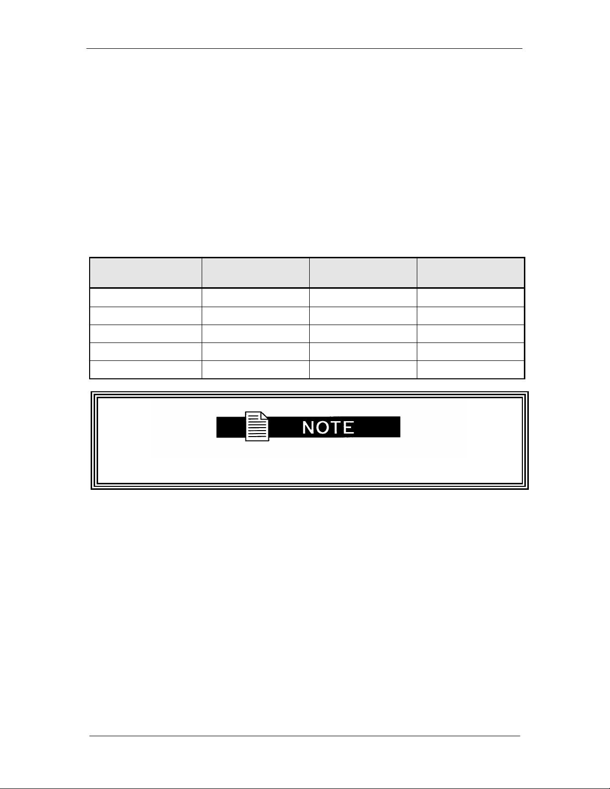
SFC1800A Synthesized Frequency Upconverter User Interfaces
4.6.2.2 Loggin g on and Pass wor d s
There ar e several available logon users each setup with a defaul t passwor d. The user must b e
logged on in or der to view or chan ge some sett ings. There are 3 levels of access rights in the
SFC1800A Upconverter. These are:
Initial Access: The default wh en no user is l ogged on.
Viewer Access: Allows its user to modify its own logon and
authentication passwords.
Operator Access: All other SNMP and security selection s can only be
accessed.
Listed in the table below are the avai l able user names and corresponding default passwords:
Sec urity User Logon Password Authentication
Password
Initial
Viewer Viewer Viewer
Privacy Password
Oper–md5 Oper Oper Oper
Viewer–sha Viewer Viewer
Oper-sha Oper Oper Oper
All entr i e s are case sensitive.
4.6.2.3 Exiting SNMP Configuration
1. Select the M ai n Menu by pressing ‘1’ followed by <ENTE R>, to go back to the top-level
Menu screen.
TM111 – Rev. 1.0 4-33
Page 58

User Interfaces SFC1800A Synthesized Frequency Upconverter
4.6.2.4 Loggin g On
1. The user must be logged on to have access to SNMP Features. To log on the SNMP
configuration, press ‘50’ followed by <ENTER> to open the Logon Dialog Box.
+ - - - - - - - - - - - - - - - - - - | Log on | - - - - - - - - - - - - - - - - - - - - - -+
| |
| 1.User ID : |
| 2.Password : |
| 3.O K 4.CANCEL |
| |
+ - - - - - - - - - - - - - - - - - - - - - - - - - - - - - - - - - - - - - - - - - - - - - - +
2. In the User ID Text Box, enter “Oper-m d5” (case sensi tive).
3. In the Password Text Box, enter “Oper” (case sensitive).
4. Select OK
4.6.2.5 Changing the Logon Password
To chan ge the password, logged on so that the “S NMP/Security” selection appear s. Press ‘5 4’
followed by <E NTER> to open the Change Logon Password dialog.
+ - - - - - - - - - - - - - | Change Password | - - - - - - - - - - - - - - - - - -+
| |
| 1.Old P assword: |
| 2.New Password: |
| 3.Re-enter New Password: |
| 4.O K 5.CANCEL |
| |
+ - - - - - - - - - - - - - - - - - - - - - - - - - - - - - - - - - - - - - - - - - - - - - - +
1. In the Old Password Text Box, enter “Oper” (case sensitive ) .
2. In the New Password Text B ox, enter the new password (case sen sitive, only * ’ s ap pear
for security).
3. Re-enter the new password to verify the desired setting.
4. Select OK
4.6.2.6 Loggin g Off
1. To log off the SNMP Configuration, press ‘51’ foll owed by <ENTER>. The followin g
confir mation message will be displayed to avoid i nadvertent exits:
You will be logged off. Are you sure? (Y/N):
4-34 TM111 - Rev. 1.0
Page 59

SFC1800A Synthesized Frequency Upconverter User Interfaces
4.6.2.7 Changi ng Your Authent ic atio n Pas s wor d
1. Select 55. foll owed by <ENTER > to open the Ch ange Passwor d Dialog.
+ - - - - - - - - - - - - - - -| Change Password | - - - - - - - - - - - - - - - - +
| |
| 1.Old Password: |
| 2.New Password: |
| 3.Re-enter New Password: |
|| 4.OK 5.CANCEL |
| |
+ - - - - - - - - - - - - - - - - - - - - - - - - - - - - - - - - - - - - - - - - - - - - - - +
2. In the Old Password Text Box, enter “Oper” (case sensitive ) .
3. In the New Passw or d Text B ox, enter the new password (case sen sitive, only * ’ s ap pear
for security).
4. Re-enter the new password to verify desired setting.
5. Select OK
4.6.2.8 Changing Your Privacy Password
To chan ge your privacy passw or d, select 56 followed by <ENTER> to open the Change
Password dial og.
+ - - - - - - - - - - - - - - - | Change Password |- - - - - - - - - - - - - - - - +
| |
| 1.Old Password: |
| 2.New Password : |
| 3.Re-enter New Password: |
| 4.OK 5.CANCEL |
| |
+ - - - - - - - - - - - - - - - - - - - - - - - - - - - - - - - - - - - - - - - - - - - - - - +
1. In the Old Password Text Box, enter “Oper” (case sensitive).
2. In the New Passw or d Text B ox, enter the new password (case sen sitive, only * ’ s ap pear
for security).
3. Re-enter the new password to verify desired setting.
4. Select OK
TM111 – Rev. 1.0 4-35
Page 60

User Interfaces SFC1800A Synthesized Frequency Upconverter
4.6.2.9 Converter Ethernet Address
1. The Modem SFC1800A High-Speed Microwave Modem Ethernet Address is configured
at the factory. It is a uni que Radyne equipment id entifier.
Example: 0010650 903EB
Do not modify the Ethernet Address. Major problems may result if
changed.
4.6.2.10 Converter IP Address
1. Select ‘39’, Converter IP Add r ess:. Enter the SFC1800A Upcon verter In ternet Address in
dot notat i on and press <ENTER>. P lease consult your network administrator for valid
addresses.
Example - 192.168.0.35
2. The IP Address that is selected will be used for the Ethernet Test that fol l ows.
4.6.2.11 Server Ethernet Address
This se ction r efers to the boot host.
1. Select 40.ServerEthAddr:. Enter th e Ser ver 12 Digit Ethern et Address and pr ess
<ENTER>. Zero out this address if not known at thi s time. The system will resolve it
dynamicall y at r un time.
Example: 0FD0640203ED or 00000000000 0
4.6.2.12 Server IP Address
This se ction r efers to the Host that will b e used to optionally boot the up converter on power-up.
The host sh ould be acceptable t o the transport layer. In other words, the transport layer need s to
be ab l e to open a connection to the en tity specified by the server IP Add r ess field .
1. Select 41.ServerIPAddr :. Enter the S er ver Inter net A ddress in dot notation and press
<ENTER>. Pl ease consult your net work administrator for valid addresses.
E xample: 192.168.0.50
2. The IP Address that is selected will be used for the Ethernet Test that fol l ows.
4-36 TM111 - Rev. 1.0
Page 61

SFC1800A Synthesized Frequency Upconverter User Interfaces
4.6.2. 13 Router I P Ad dress
Select 42.RouterIPAddr :. Enter the router Intern et Address in dot notation and press <ENTER>.
Please consult your network administr ator for va lid addresse s.
E xample: 192.168.0.254
4.6.2.14 IP Address Mask
In the mask (more clear ly seen in the binary f or mat), binary 1s indicat e the position of the netwo r k
and subnet portion of the IP Address while binary 0s identify bits that represent the individual
interfaces. To recognize a subn et, each system in the subnet must have t he same subnet mask.
Please consult your network administr ator for a valid address class mask.
1. Select 43.IPAddr essMask:. En ter the I P Address mask in dot not ation and press
<ENTER>.
E xample: 255.255.0.0
4.6.2.15 Boot Mode (Optional)
1. Select 37.Boot Mode : from the Control s Menu and press <ENTER>. Scr ol l throu gh the
variou s selections to ‘NVBOO T’ and press <ENTER>. The above settings will be
enab l ed the next time the system is rebooted. I f a bootp server is avai labl e, th e
up converter can b e r emotely configured by selecti ng bootp m ode. This option is currently
not availabl e.
4.6.2.16 Community
Each managed stat ion controls its own local MIB and mu st be able to cont r ol the use of that M IB
by a number of management station s. This r elates t o securi ty concer ns. A m anaged MIB such
as the upconverter n eeds to protect itse l f from unwanted and unauthorized access. SNMP, as
defin ed in RFC 1157, provid es only a limited capability for such security, namely t he concept of a
comm unity. An SNMP C om m unity is the relationship between an SNMP Agent and Management
Stations.
1. To set the comm unity string on th e SF C 1800A Upconverter, sel ect 34.Comm unity:.
En ter the d esired community name and press <ENTE R>.
E xample: “pub lic”
4.6.2.17 Trap Type and Trap Hosts
Traps enable the converter to noti fy the management station of sign ificant events such as alarms.
Versi on1 and version2 Trap s are supported at this time. These are Operator selectable usi ng
Term i nal Command Number 30. The messages ar e sent to specific pre-defined hosts. The
Primary and Secon dary Trap Hosts IP Addresses are setup using Terminal Commands 31 and
32 . Each host should be accep table to the transpor t layer. I n oth er words, the transport layer
need s to be able to open a connecti on to th e entities specified b y t he trap host fields.
4.6.2.18 Trace Mode
1. For debugg i ng purposes, a t r ace mode is specified by the Operator users for various
diagnostic levels.
TM111 – Rev. 1.0 4-37
Page 62

User Interfaces SFC1800A Synthesized Frequency Upconverter
4.6.2.19 SNMP V1 & 2 Access View
The default access rights for Version 1 and 2 SNMP users are minimal. They are limited to a
system view, and a description of the upconverter System and Contact Information. For
add i tional i nformation, go to View-Based Access Control Section. To acco mmodate older
systems, an Operat or user may mod i fy t hese acce ss rig hts to allow fu ll or partial r ead/ write
access. SN M P Version 1 and 2 does not use any security measures, therefore users should be
very careful when changing access rights.
4.6.2.20 Key Generation Mode
The password l ocalization algorithm i s intensive enough that the M otorola 68332 Embedd ed
Processor cannot h andle the process in a timely manner. This selection al l ows the Operator use r
to optionally stor e l ocalized keys i n non-volatil e memor y. These keys correspond to a se t of
passwords and Modem IP Address. If eith er chang es, the SNMP agent automatically
recalculates the new keys and stor es them in non -volat ile memory (only if the Key Generation
Mode is set t o ‘ STORE’ ) .
4.6.2.21 Context Engine ID
“contextEngineID” is the uni que identifier of the u pcon verter SNMP Eng i ne that pr ovides services
for sending and rece i ving messages, authenticati ng and encrypting messages, and controlling
access to m anaged objects.
1. The Context E ngine ID, 80000A1F01AC126 4B0, is formatted as follows:
a. Th e first 4 bytes are the Radyne Pri vate Enterprise Number (2591).
b. The ver y f irst bit is set to 1, for exampl e: 80000A1F (H).
c. The fifth byte indicates how the 6
means it’ s an IPv4 Address.
d. The last 4 bytes are th e IP Addr ess 172.18.100.176 (AC1264B0) .
th
and remainin g bytes are formatted. A ‘1’
4.6.2.22 View-Based Access Control
SNMPv3 defines a m ethod of access control known as the View-based Access Control Model
(VA CM). It i s defin ed as a means to restrict access to particu lar subsets of vari ables based on the
identity of t he manager and the security level used in the request.
A view is a group of MIB variables on the agent. The ag ent defines a view for each user based
on the user ident i ty (secu r ityName) and se curity level. F ol lowing are t he major views:
Sy st em view: Access to system description
MIB-II view: Access to the standard MIB-II informat i on
Device view: Access to the device pr ivate information
World view: Access to every manag ed object in the MIB
Following are the a vailabl e access groups:
4-38 TM111 - Rev. 1.0
Page 63
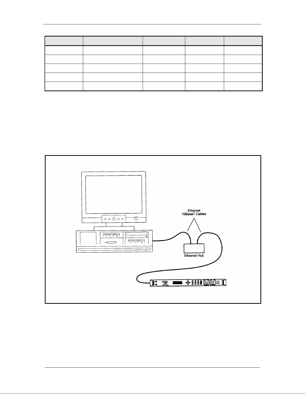
SFC1800A Synthesized Frequency Upconverter User Interfaces
Group Context/Community Secur ity Le vel Read Access Write Access
NULL mib2 NoAuth/noPriv System view NONE
Viewer mib2 Auth/noPriv MIB-II view NONE
Viewer Dev Auth/Priv Device view NONE
Oper mib2 Auth/noPriv MIB-II view MIB-II view
Oper Dev Auth/Priv Device view Device view
The NULL Security Name is for backward com patibility with SNM P Version 1 and 2 management
stations ( securi ty nam es are not defined for earli er protocols). In this case, the contextName in
each view may refer to either a context Nam e or a communityName. The secu r i tyLevel would then
be n oAuth/noPri v.
4.6.3 Connecting the Ethernet Cable and Testing the Link
1. Connect the computer to the upconverter Ethernet port (J9) using the RJ-45 to RJ-45 10
Base-T Cables via a hu b as shown i n Figure 4-3.
Figure 4-3. Ethernet Connection
TM111 – Rev. 1.0 4-39
Page 64

User Interfaces SFC1800A Synthesized Frequency Upconverter
4.6.3.1 Ping Progr a m
1. PING is an app l ication th at uses th e ICMP protocol t o r eport if a host is responding. To
check whether th e SFC1800A Upconverter is r eachable, use the PING p r ogram installed
on your computer along with the modem IP Address set in Section 3.2.3 .
Exampl e : pin g 19 2.168.0.35
2. If ever ythin g is functioning co r r ectly, replies from the mod em will ap pear on the computer
screen along with the time it took to respond. If unsuccessful, verify the fol l owing:
a. Th e cables are secured.
b. The Link Lig ht is ill umin ated.
c. The IP Address that is used matches the Modem’s IP Address.
d. The Server and Modem ar e on th e same subnet.
4.6.3.2 SNMP Test
1. Once it is determined that the SFC1800A Upconverter i s reachable, com pile the custom
Managemen t Information Base (MIB) for use by the Network Management Station
(NMS) . The MIB uses a hierarch ical naming scheme. Each managed object i n the
up converter i s identified by an Object Identi fier ( OID), a sequence of non-negative
integers that uni quely describes the path taken thr ough th e hierarchical stru ct ure.
2. Usin g the up converter IP Ad dress, perform a Walk of the MIB to retrieve all t he MIB
objects managed in the upconverter.
4.6.4 Management Information Base Structure
This section defines the terminology and hi er ar chy associat ed with management information base
structure at Radyne.
4.6.4.1 Simple Network Management Protocol (SNMP)
Simple Netwo r k Manag ement Prot ocol (SNM P), as its name su ggests, is a relatively simple
prot ocol by which m anagement informat i on for a network d evice m ay be inspect ed and/ or altered
by rem ote administrator s.
4.6.4.2 The Management Information Base (MIB)
Managemen t objects are defined in the Management Information Base ( M IB), which uses a
hierarchical naming scheme. In this scheme, an Object Identifier (OID) identifies each object.
The OI D is a sequence of non-negative integers that uniquely describes the p ath taken th r ough
the hierarchical structure.
MIB objects may then be specified either from the R oot (which has no designator ) , or alternative ly
from anywher e within the hierarchical structure.
For example: 1.3.6.1.4.1.2591.4 is equivalent to {iso(1). org(3). dod(6). internet(1). private(4).
enterprises(1). Radyne(2591). RCS10L(4)} (See Figure 4-4).
In general, we ar e main ly concerned wi th just two groups that resi de in the internet subtree,
namely the mgmt, and private groups. For complet eness however, the four major groups are
discussed below:
4-40 TM111 - Rev. 1.0
Page 65

SFC1800A Synthesized Frequency Upconverter User Interfaces
Directory {internet 1} 1.3.6.1.1
This area was reserved to describ e how the OSI di r ectory str ucture m ay be used in the Internet.
To date t his has not been implemented and therefore is of little interest to us.
Mgmt {internet 2} 1.3.6.1.2
This area was reserved to describ e objects in the standard MIB. As RFCs defining new groups
are ratified, the Inter net Assigned Numbers Authority (IAN A) assi gns new group IDs.
Experimental {internet 3} 1.3.6.1.3
This subtree provides an area where experimentation i s carried out. Only those organizations
directly involved in the experiment have any interest i n this subtree.
Private {internet 4} 1.3.6.1.4
This is possibly the most import ant area of t he MIB, since it is within this sub tree that vendors
place object s specific to their partic ular d evices. B eneath the private branch, there is a subtr ee
called enterprises, beneath wh ich each vend or may define its own stru ctur e. Vendors are
assigned Private Enterprise Numbers (PENs) that uniquely identify them. They may then place
all obj ects specific to th eir devices in this tr ee, provided of course that the object conforms to the
format defined by SMI. Radyne’s Privat e Ent er prise Number i s 2591 . Ot her pr oducts are added
to Radyne’s subtree as they b ecome remotely manageable through SNMP.
Figure 4-4. Object Identifiers in the Management Information Base (Sheet 1 of 2)
TM111 – Rev. 1.0 4-41
Page 66

User Interfaces SFC1800A Synthesized Frequency Upconverter
Figure 4-4. Object Identifiers in the Management Information Base (Sheet 2 of 2)
Refer to Appendix B for MIB listing.
4-42 TM111 - Rev. 1.0
Page 67

SFC1800A Synthesized Frequency Upconverter Rear Panel Interfaces
Rear Panel Interfaces
5
5.0 SFC1800A Upconverter Connections
All SFC1800A Upconverter connections ar e made to labeled connector s. Any connection to an
SFC1800A Upconverter must be made with the app r opriate mating conn ector. R efer to Fig ure 51 for the various co nnector locations.
Figure 5-1. SFC1800A Upconverter Back Panel
5.1 Power
Located on the left si de of the SFC1800A Up converter R ear Panel is the AC Power Input
Connector. This connector is an IEC/EN60320/C13 Power Entry Module. The unit is powered
from a 100 – 240 VAC, 50 – 60 Hz source. Maximum unit power consumption is 50 W. The
switch tu r ns power on and off to the unit. A chassi s ground connection can be made at the #1 0
size stud located between the IF (J2) and Ethernet (J9) connectors.
The Power Cord /connector for the SFC1800A Upco nverter is a sup plied item.
5.2 10 MHz Ref In (J4)
The Reference Input is a 50 Ohm BNC-F connector ( J4) allows the operator to synchronize t he
synt hesizer of the converter to an e xternal 10 MHz referen ce. When an exter nal re ference i s
properly ap plied to the refe r ence input, the external reference LED will illuminate on the front
panel.
5.3 10 MHz Ref Out (J3)
The 10 MHz Reference Out (J3) is a 50 Ohm BNC-F Connector that provides a 10 MHz square
wave, 50 Ohm AC coupl ed reference output signal at 0 dBm. In normal operation (no ext er nal
reference) this output is synchronous with the internal high stability 10 MHz reference.
TM111 – Rev. 1.0 5-1
Page 68

Rear Panel Interfaces SFC1800A Synthesized Frequency Upconverter
5.4 Test/Fault (J7)
The Test/Fau lt connector (J7) i s a status port that allows mon i toring of several system st atus
indicati ons at the back panel. These items are described in Table 5-1.
Table 5-1. J7 – Test/Fault I n ter face – D-Sub 9-Pin Female Connector
Pin No. Signal I/O Description
1 N.C. N.A. No Connect
2 IF_LO_FAULT O 1 = LO Faul t C ondition
3 GND N.A. Ground
4 IF_SIG_DET O Detected P ower Level of IF Signal 0 to 5
VDC
5 N.C. N.A. No Connect
6 RLY_NO N.A. Form-C relay normally open contact,
summary fault
7 RLY_NC N.A. Form-C relay norm al ly closed con tact,
summary fault
8 RLY_C N.A. Form-C relay common contact, summary fau lt
9 RF_SIG_DET O Detected Power Level of RF Signal
(Upconverter only, 0 - 5 VDC)
5.5 Operator Serial I/O (J8)
The Operator S er ial I/O P or t (J8 ) i s a DB-9 Femal e C onnector. This port provides a serial
interface that ca n be con fi gured as either an RS-232 or RS-485 int er face and allows the user to
remotely control all of th e featu r es outl i ned in the Serial Protoco l ( See Section 4.2, Remote Port
User I nterfaces). Th e serial port co mes configured as an RS-232 Serial P or t for DCE unless
other wise in dicat ed. The pinout for this interface is listed in Table 5-2.
The function of Pin 1 and Pin 9 depends on whether the protocol is set to
RS-232 or RS-485 (Front Panel LCD Menu: SYSTEM < REMOTE PORT <
REMOTE LINE).
5-2 TM111 - Rev. 1.0
Page 69

SFC1800A Synthesized Frequency Upconverter Rear Panel Interfaces
A
485 R eceive
485 Transmit
Pin No.
Table 5-2. J8 – Operator Serial I/O Port – D-Sub 9-Pin Female Connector
Pin No. Signal I/O Description
1 RX_485 –
RX_232
I Inverted RS-
RS-232 receive
2 TX_485-B O Non-Inverted RS-485 transmit
3 RX_485-B I Non-I nverted RS-485 receive
4 DTR N.A. Connected internally to Pin 6-DSR
5 GND N.A. Ground
6 DSR N.A. C onnected internall y to Pin 4-DTR
7 RTS N.A. Connected int er nally to Pin 8-CTS
8 CTS N.A. Connected int er nally to Pin 7-RTS
9 TX_485 – A
TX_232
O Inverted RS-
RS-232 Transmit
If the RS-232 op tion is chosen , an adapter mu st be used between J8 and th e serial cable to the
DTE. One end of the ad apter will be a DB-9-M connector, wh ich plugs int o J8 on the upconverter
back panel . The other end will be a DB-9-F connector, which pl ugs int o the PC se rial port or
dumb terminal. The pinout is given in Figure 5-3.
Table 5-3. – RS-232 Adaptor – Operator Serial I/O Port
Pin No.
DB-9 Male to Upconverter J8
DB-9 Female to DTE
1 3
5 5
9 2
2,3,4,6,7,8 N.A.
5.6 IF Out (J2)
The IF Out Connector (J2) is a 75 Ohm BNC-F Connector. Outputs are within 50 – 90 MHz for
standard units and 100 – 180 MHz for units equipped with 140 MHz.
TM111 – Rev. 1.0 5-3
Page 70

Rear Panel Interfaces SFC1800A Synthesized Frequency Upconverter
5.7 Terminal (J6)
The Terminal Port allows for co mpl ete control and monitoring of all Upconvert er parameters and
functions via an RS-232 Ser i al Interface. The interface comes config ured as a DCE device. The
pinout is given in Table 5-4.
Table 5-4. J8 – Terminal Port – D-Sub 9-Pin Female Connector
Pin No. Signal I/O Description
2 TX_232 O RS-232 transmit
3 RX_232 I RS-232 receive
5 GND N.A. Ground
1, 4, 6, 7, 8, 9 N.A. N.A. No Connect
5.8 Ethernet (J9)
The Ethern et connector can be used for monitor & control functions of the upconverter. The
ph ysical in terface is a standard RJ-45 connector.
5.9 Equipment RS-485 (J10), Standard Backward Compatible Interface
The Equipment Multi-Drop, Full-Duplex, Bi-direct ion al RS -485 Interface (J10) allows
comm unication b etween converters. Beca use the RS-485 Interface uses a master /slave
(talke r /listener ) config uration, t he con verter th at is d esignat ed as the backup will automat i cally be
established as the master. Under normal R S-485 p r otocol, the master will poll a specific slave b y
address and only then will the slave unit respond. The swapping of Transmit Data and Receive
Data is accomplished in the inter-converter cables, as the hardware in terface i s identi cal for all
converters. Refer t o Table 5-5 for the connector pinout.
Table 5-5. J6 – Equipme nt RS-485 Interface - D-Sub 9-Pin Female Connector
Pin No. Signal
1 GND N.A. Ground
2 I2C_SCL O I2C Clock
3 N.C. N.A. No Connect
4 TX_485-B O Invert ed RS-485 transmit
5 TX_485-A O Non-Inverted RS-485 transmit
6 I2C_SDA I/O I2C Data
7 N.C. N.A. No Connect
8 RX_485-B I Inverted R S-485 r eceive
9 RX_485-A I Non-Inverted RS-4 85 receive
5-4 TM111 - Rev. 1.0
I/O Description
Page 71

SFC1800A Synthesized Frequency Upconverter Rear Panel Interfaces
Figure 5-2. DIP Switch Settings for DCE
5.10 B/U Switch Interface (J5)
The Backup Switch Interface (J5) is a D Sub 15 Pin Female Connector that conn ect s each
converter with the RCU101 or RCU1 08 Backup Switch Unit. This cable is not daisy-chained
between converters, but serves as a direct link for each converter in the configuration, whether
they are the individual online converters or the backup unit. This interface finds use in both the
1:1 and 1:N configuration type switches. The pinout of the switch is listed in Table 5-6.
TM111 – Rev. 1.0 5-5
Page 72
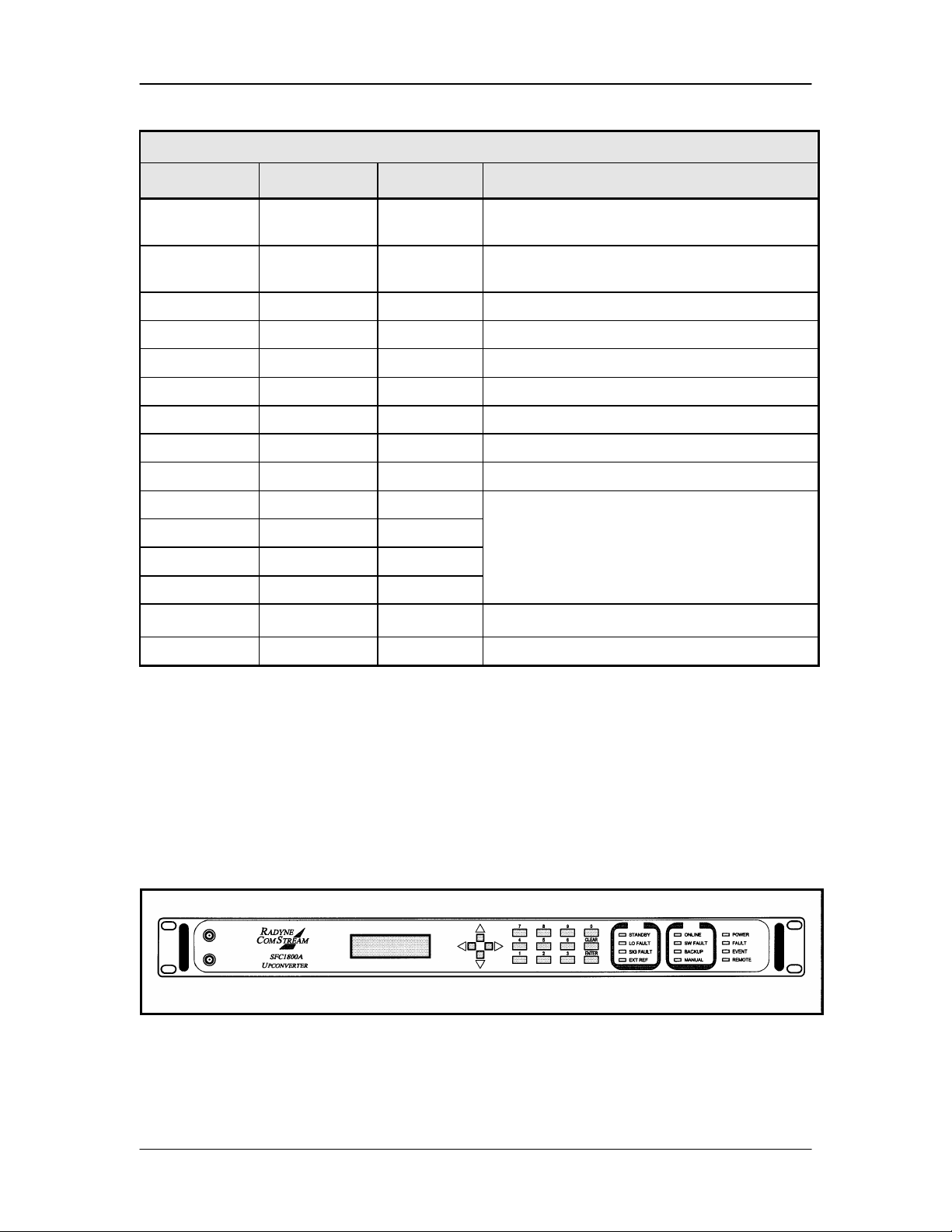
Rear Panel Interfaces SFC1800A Synthesized Frequency Upconverter
Table 5-6. J5 – B acku p Swit ch In t erface – D-Sub 15-Pin Female Connector
Pin No. Signal I/O Description
1 RLY_NO N.A. Form-C relay normally open contact,
summary fault
5 RLY_NC N.A. Form-C relay nor mally closed contact,
summary fault
9 RLY_C N.A. Form-C relay common contact, summ ar y fau l t
13 GND N.A. Ground
2 +15_OR N.A. D i ode Or’d +15 VDC from converter
6 FAULT_INT1 Input RCU101 O NL INE status ind icator
10 FAULT_INT2 Input RCU101 Manual Mode indicator A
14 FAULT_INT3 Input RCU101 Manual Mode indicator B
3 FAULT_INT3 N.A. Spare
7 ID_INT0 Input
11 ID_INT1 Input
15 ID_INT2 Input
4 ID_INT3 Input
Converter Switch position ID bits.
8 INT N.A. Spare
12 RMT Output RCU101 Manual Remote Cont r ol
5.11 RF In (J1)
The RF I n (J1) is the R F Input of t he SFC1 800A Upconverter. It i s an N-Type Female Connector
for the SFC1 800A, and an SMA Female Connector for the SFC1450A.
5.12 Monitor Ports
The SFC1800A Upconverter have Mon i tor Ports located on the Fr ont Pan el ( Figure 5-7) that
allow the operator t o moni tor the IF Output and RF Input.
Figure 5-7. SFC1800A Upconverter Front Panel with Monitor Ports
5-6 TM111 - Rev. 1.0
Page 73

SFC1800A Synthesized Frequency Upconverter Rear Panel Interfaces
5.12.1 IF Monitor Port
The IF M onitor Port is an SMA-F Type Connector located on the front panel that allows
monitoring of the upcon verter's IF Output. The power level of the monitored signal will be-15 dB
nominal below the l evel prese nt at J2.
5.12.2 RF Monitor Port
The RF Monitor port is an SMA-F Type Connector l ocated on th e front panel th at allows
monitoring of the upcon verter's R F Input. The power level of the moni tored signal will be-15 dB
nominal below the l evel prese nt at J1.
5.13 Optional Chain Switching Module
5.13.1 (J10)
J10 i s an SMA-F Type C onnector. When connected to J1 in the chain switching configuration, it
provid es a direct path for the RF I nput th r ough th e swi tch m odule for non-faulted conditions.
5.13.2 (J11)
J11 i s an SMA-F Type C onnector. It is the RF Input of the SFC1800A Upconverter i n the chain
switching configuration.
5.13.3 (J12 and J13)
J12 and J13 ar e SMA-F Type Connectors t hat p r ovides an R F signal path from the backu p
converter to each converter i n the redun dancy chain in a non-fault condition. During a fault
condition, the faulted convert er changes the fl ow from J13 to J12 to J13 to J11.
5.13.4 (J14)
J14 i s a BNC F em al e Connector. It is connected to the Converter I F Output ( J2). In a nonfaulted condition, the through path of the switch module is from J14 to J15.
5.13.5 (J16 and J17)
J16 and J17 ar e BNC Female Con nectors that provide an IF si gnal path from the backu p
converter to each p r i mary con verter in th e converter chain. In a fault ed condition , the switch will
change th e IF flow from the backup converter to the IF Out put (J15).
TM111 – Rev. 1.0 5-7
Page 74

Rear Panel Interfaces SFC1800A Synthesized Frequency Upconverter
5.13.6 (J18)
J18 i s a D Sub 25 Pi n Female Connector that is a combination of the RS-484 and B/U Switch
Interfaces. This connector con nects each co nverter in a daisy chain configurat ion with t he
backup master converter.
Table 5-7. J18 – D-Sub 25-Pin Female Connector
Pin No. Signal I/O Description
1 +15 V_SW --- +15 VDC Power Bus
2 +15 V_SW --- +15 VDC Power Bus
3 TX_485-A_SW Out Inverted RS-485 Transmit
4 RX_485-A_SW In Inverted R S-485 R eceive
5 I2C_SDA_SW I/O I2C Data
6 ID_OUT_SW0 Out Con vert er Position ID Bit 0
7 ID_OUT_SW2 Out Con vert er Position ID Bit 2
8 FAULT_SW1 In Switch Fault Indicator – Prime 1
9 FAULT_SW3 In Switch Fault Indicator – Prime 3
10 FAULT_SW5 In Switch Fault Indicator – Prime 5
11 FAULT_SW7 In Switch Fault Indicator – P rime 7
12 GND --- Ground
13 GND --- Ground
14 +15 V_SW --- +15 VDC Power Bus
15 N/C --- No Connection
16 TX_485-B_SW Out RS-485 Transmit
17 RX_485-B_SW In RS-485 Receive
18 I2C_SCL_SW Out I2C Clock
19 ID_OUT_SW1 Out Converter Position ID Bit 1
20 ID_OUT_SW3 Out Converter Position ID Bit 3
21 FAULT_SW2 In Switch Fault Indicator – Prime 2
22 FAULT_SW4 In Switch Fault Indicator – Prime 4
23 FAULT_SW6 In Switch Fault Indicator – Prime 6
24 FAULT_SW8 In Switch Fault Indicator – Prime 8
25 GND --- Ground
5-8 TM111 - Rev. 1.0
Page 75

SFC1800A Synthesized Frequency Upconverter Rear Panel Interfaces
5.13.7 (J19)
J19 i s a D Sub 25 Pi n Female Connector that is a combination of the RS-484 and B/U Switch
Interfaces. This connector con nects each co nverter in a daisy chain configurat ion with t he
backup master converter.
Table 5-7. J19 – D-Sub 25 -Pin Female Connector
Pin No. Signal I/O Description
1 +15 V_SW --- +15 VDC Power Bus
2 +15 V_SW --- +15 VDC Power Bus
3 TX_485-A_SW Out Inverted RS-485 Transmit
4 RX_485-A_SW In Inverted R S-485 R eceive
5 I2C_SDA_SW I/O I2C Data
6 ID_IN_SW0 In Converter Position ID Bit 0
7 ID_IN_SW2 In Converter Position ID Bit 2
8 FAULT_SW1 Out Switch Fault Indicator – Pr ime 1
9 FAULT_SW3 Out Switch Fault Indicator – Pr ime 3
10 FAULT_SW5 Out Switch Fault Indicator – P rime 5
11 FAULT_SW7 Out Swit ch Fault Indicator – Prime 7
12 GND --- Ground
13 GND --- Ground
14 +15 V_SW --- +15 VDC Power Bus
15 N/C --- No Connection
16 TX_485-B_SW Out RS-485 Transmit
17 RX_485-B_SW In RS-485 Receive
18 I2C_SCL_SW Out I2C Clock
19 ID_IN_SW1 Out Converter Position ID Bit 1
20 ID_IN_SW3 Out Converter Position ID Bit 3
21 FAULT_SW2 Out Switch Fault Indicator – P rime 2
22 FAULT_SW4 Out Switch Fault Indicator – P rime 4
23 FAULT_SW6 Out Switch Fault Indicator – P rime 6
24 FAULT_SW8 Out Switch Fault Indicator – Prime 8
25 GND --- Ground
TM111 – Rev. 1.0 5-9
Page 76

Rear Panel Interfaces SFC1800A Synthesized Frequency Upconverter
5-10 TM111 - Rev. 1.0
Page 77

SFC1800A Synthesized Frequency Upconverter Maintenance and Troubleshooting
Maintenance and Troubleshooting
6
6.0 Periodic Maintenance
Radyne SFC1800A Upconverter are designed to provide many thousands of hours of continuous
operat ion. Nor mal ag ing and drifting of electroni c components can cause the accu racy of the
converter to chan ge over time. As with any converter , th ese changes will affect t he frequency
accuracy and frequency conversion amplitude accuracy over time.
6.1 Failure Analysis
Faults in the converter are limited in sco pe to either a LO Fault or a Signal Fault . Other faul ts,
such as a failur e of th e micro contr ol ler, m ay or may not provide an indica tion.
TM111 – Rev. 1.0 6-1
Page 78

Maintenance and Troubleshooting SFC1800A Synthesized Frequency Upconverter
6-2 TM111 - Rev. 1.0
Page 79

SFC1800A Synthesized Frequency Upconverter Technical Specifications
Technical Specifications
7
7.0 Introduction
This se ction defines the t echnical performance parameters and sp ecificati ons for the SFC1800A
Synthesized Frequency Upconverter.
7.1 Output Characteristics
Frequency: 17.30 to 18.40 GHz
Impedance: 50 Ohm
Return Loss: >16 dB
P1 dBm Output: + 15 dB m Minim u m
Output Attenuation: 0 - 20 dB Continuously Variable in 0.1 dB Steps
Connector: N, Type-F
7.2 Input Characteristics
Frequency: 70 MH z ±18 MHz St andard, 140 MHz ± 36 MHz Optional
Impedance: 75 Ohm
Return Loss: >23 dB
P1 dBm Input: +10 dBm (Input Attenuator @ 30 dB)
-15 dBm (Input Attenuator @ 0 dB)
Pin Nominal: +5 dBm (Input Attenuator @ 30 dB)
-25 dBm (Input Attenuator @ 0 dB)
Connector: BNC Type F
Performance specifications guaranteed at nominal levels only.
7.3 Transfer Characteristics
Type: Double Conversion, No Spectral Inversion
Gain: 30 dB Maximum @ 0 dB Total Attenuation
Gain cont r ol: 50 dB in 0.1 dB Incr eme nts
(30 dB to -20 dB Conversion Gain)
Gain Ripp le: ±0.25 dB/36 MHz Typical, ±0.50 dB Maximum
Gain Slop e: ±0.05 dB/MHz
Gain stability: ±0.25 dB/24 hr., ± 1.0 dB; 0 to 50°C
TM111 – Rev. 1.0 7-1
Page 80

Technical Specifications SFC1800A Synthesized Frequency Upconverter
Spurious: -80 dBm LO Related Spurious (In-Band) at
Maximum G ain
-60 dBc Sign al Related Spurious (I n-Band ) at
Mini mum Attenuation
Third Order Intercept: + 27 dB m -44 dBc IM D Two Tones wit h +5 dBm Total
Output Power
AM/ PM Conversion: 0.1°/dB @ +5 dBm Output
Grou p Delay Li near: 0. 025 nse c/MHz
Parabolic: 0.005 n sec/MH z
2
Ripple: 1 nsec p-p
Carrier Mute: 80 dBm Mi nimum
7.4 Frequency Synthesizer Characteristics
Resolution: 125 kHz Step Size
Accuracy: ±5 x 10
Stability: ±5 x 10
(0 to 50° C) ± 1 x 10
Accuracy: ±5 x 10
-9
-9
Over Temperat u re
-9
-9
/24 Hours
7.5 Single Side Band Phase Noise
Offset: 10 Hz: -50 dBc /H z
100 Hz: -70 dBc/H z
1 kHz: -80 dBc/Hz
10 kHz: -88 dBc/Hz
100 kHz: -95 dBc/Hz
1 MHz: -110 dBc/Hz
External Reference : 10 MHz, 0 dBm, 50 Ohm
(5 MHz Optional)
7.6 Operator Interface
Front Pan el : Keypad Control, and LED and LCD Indicators
Remote Interfaces: Terminal (RS-232) , ASCII and RLLP (R S-232/RS-485)
Serial Int er faces, and SNMP (Ethernet )
Rear Panel Connecti ons: RF Output (N-Type)
IF Input (75 Ohm BNC)
Oper ator Seri al Port (DB-9)
10 MHz REF in (50 Ohm BNC)
10 MHz REF Out (50 Ohm BNC)
Fault/Test (DB-9)
Switch Interface (D B-15)
Equ i pment RS-485 Interface (DB-9),
IEC /EN60320/C13 Power Entry Module/ Switch
#10 Ground Lug
Front Pan el Test Ports: RF monitor -15 dB SMA-F, IF Mon i tor -15 dB SMA-F
7-2 TM111 - Rev. 1.0
Page 81

SFC1800A Synthesized Frequency Upconverter Technical Specifications
7.6.1 Convert er Sett ing s
Monitored and/or contr olled from Frequency
the Front Panel or remotely, usi ng Chann el Gain
the RS-232/RS-485 or Ether net The Current Channel
remote port : Gain Offset
Event Buffer
Fault s Status and M ask
Power Supply Voltag es
Frequency Ref er ence Statu s and Offse t Control
Input Attenuation
Remote Protoco l
Baud, Line, and Echo M odes
Carrier Control and Status
Conver ter Band an d User Min imum/ M aximum
Frequencies
Converter and Frequency Type
Terminal Emulation and Baud Rate
RF Detector
IF Detector an d DAC A ttenu ation Voltages
7.6.2 Switch Sett ing s
Monitored and/or contr olled from Priority
the Front Panel or remotely using All Available Prime Summary Fault
the RS-232/RS-485 or Ethernet Fault Delay
remote port ( backup only): All Availabl e Prim e Learn Status
Force Backu p
All Available Prim e Backup Test Status
Learn Cont r ol
All Available Prime Configuration Change Status
Backup Testing
All Available Prime Relay Status
Compensation Control
All Available Prim e C onvert er Types
7.6.3 LED Indicators
Standby
LO Fault
Signal Fau lt
External Reference Online
Backup
Software Fault
Manual (Backup Only)
Power
Fault
Event
Remote
TM111 – Rev. 1.0 7-3
Page 82

Technical Specifications SFC1800A Synthesized Frequency Upconverter
7.7 Physical Characteristics
Size: 19 .0" x 1.73 " x 21.0" Deep
(48.26 cm x 4.44 cm x 48.26 cm)
Weight: 12 lb. (5.44 kg)
Primary Power: 100 to 240 VAC, 50 to 60 Hz, 1.0 A
Power Consumption: 50 Watts
7.8 Environmental Characteristics
Temperature: 0 to 50°C
Humidity: To 95% Non -Condensing
Altitude: To 8,000 ft. (2438 m) AMSL
Shock and Vibration: No loss of frame synch r onizat ion at the BER Test Set
du e to a standard hammer drop test on any outside
surface of the converter. Likewise, no loss of frame
synchronization for temperature gradients of ± 22°C/Hr.
Stor age Temp er ature: -32 to +65°C, to 99% Non-Condensing
7-4 TM111 - Rev. 1.0
Page 83

SFC1800A Synthesized Frequency Upconverter Appendix A
Remote Operations
A
When new features are added to Radyne, Inc. equipment, the control
parameters are appended to the end of the Non-Volatile Section of the
Remote Communications Specification, and status of the features, if any,
are added at the end of the Volatile Section. If a remote M&C queries two
pieces of Radyne, Inc. equipment with different revision software, they
could respond with two different sized packets. The remote M&C MUST
make use of the non-volatile count value to index to the start of the Vol atile
Section. If the remote M&C is not aware of the newly added features to the
product, it should disregard the parameters at the end of the Non-Volatile
Section and index to the start of the Volatile Section.
Before creating any software based on the information contained in this
document, contact the Radyne, Inc. Customer Service Department (602437-9620) to find out if the s oftware revis ion for that piece o f equipment is
current and that no new features have been added since the release of this
document.
A.1 SFC1800A Upconverter Opcode Command Set
The conve r ter opcode command set is listed below:
Command Opcode
Quer y module identificati on 2403h
Quer y co ntrol mode 2404h
Quer y so ftware revisi on number 3004h
Quer y firmware part number and rel ease date 3005h
Query time 240Eh
Quer y date 240Fh
Query time an d date 2410h
Quer y co nverter status 3000h
TM111 – Rev. 1.0 A-1
Page 84

Appendix A SFC1800A Synthesized Frequency Upconverter
Query response
<1>
Identification
number
Quer y co nverter configur ation 3001h
Query switch status 3002h
Query switch configuration 3003h
Command co ntrol m ode 2201h
Command set time 2C04h
Command set date 2C05h
Command se t time and date 2C06h
Command clear latched alar ms 2C03h
Command se t frequency for the given channel 3012h
Command se t gain for the g i ven channel 3013h
Command set channel 3014h
Command se t carrier control 3015h
Command se t input attenuation 3016h
Command set converter configuration 3017h
Command se t converter alarm masks 3018h
Command set backup mode 3030h
Command force a manual backup 3031h
Command lear n con verter configuration 3032h
Command lear n all converter config urations 3033h
Command backup test converter configuration 3034h
Command backup t est all co nverter configurations 3035h
Command se t comp ensation contr ol 3036h
Command se t converter co mpensati on 3037h
Command se t all converter compensations 3038h
Command se t converter prior i ty 3039h
Command se t all converter pr iorities 303Ah
Command se t switch alarm masks 303Bh
A.2 Converter Queries
Opcode: <2403h> Query Control Mode
A-2 TM111 – Rev. 1.0
Page 85

SFC1800A Synthesized Frequency Upconverter Appendix A
Query response
<1>
Control Mode
0 = Local, 1 = Terminal, 2 = Rem ote, 3 = Ethernet
Query response
<1>
Revision
Number
Binary value with i m plied decimal point, 35 means release 3.5
Query response
<8>
Part N umber
String
FW4835xx, xx represents the release version, example –B
Query response
<1>
<1>
Hour
Second
0 – 23
0 – 59
Query response
<1>
<1>
Year
Day
0 – 99
0 – 30
Query response
<1>
Year
0 – 99
Opcode: <2404h> Query control mode
Opcode: <3004h> Query software revision number
Opcode: <3005h> Query firmware part number and release date
<8>
String
Release Date
ASCII representation of release d ate dd/mm /yy
Opcode: <240Eh> Query time
<1>
Minute
0 – 59
Opcode: <240Fh> Query date
<1>
Month
0 – 11
Opcode: <2410h> Query time and date
<1>
<1>
<1>
<1>
<1>
TM111 – Rev. 1.0 A-3
Month
Day
Hour
Minute
Second
0 – 11
0 – 30
0 – 23
0 – 59
0 – 59
Page 86

Appendix A SFC1800A Synthesized Frequency Upconverter
Query response
<1>
Converter
0 = Standby, 1 = Online, 2 = Faulted, 3 = Setup
Query response
<4>
Frequency
Binary value in 125 kHz steps
Opcode: <3000h> Q u ery co nverter stat u s
<1>
<1>
<1>
<1>
<1>
<1>
<1>
<1>
<1>
<1>
<1>
<1>
Status
Switch Status
Converter Type
Conver ter Band
Frequency Type
Referen ce T ype
Major Alarm
Status
Minor Alarm
Status
Latched M aj or
Alarm Status
Latched Minor
Alarm Status
Output
Attenuat or D AC
Voltage
IF Input Power
Voltage
RF Det ector
Voltage
Opcode: <3001h> Query converter configuration
0 = Not Present, 1 = Present
0 = Down, 1 = Up
0 = C-Band, 1 = Ku-Band
0 = 70 MHz, 1 = 14 0 M H z
0 = In ternal, 1 = External
Bit 0 = LO Faul t
Bit 1 = Signal Fault
Bits 2 - 7 = Spares
Bits 0 - 7 = Spares
Bit 0 = LO Faul t
Bit 1 = Signal Fault
Bits 2 - 7 = Spares
Bits 0 - 7 = Spar es
<4>
<1>
<1>
<1>
A-4 TM111 – Rev. 1.0
Gain
Input
Attenuation
Channel
Carrier Control
- 20.0 dB to +30 .0 dB dependin g on input attenuator se tting
0 - 31, Upconvert er only
1 - 30
0 = Off, 1 = On
Page 87

SFC1800A Synthesized Frequency Upconverter Appendix A
<1>
Referen ce T ype
0 = In ternal, 1 = External
Query response
<1>
Major Alarm
Prime
Bit 0 = Polling Fault
Query response
<2>
Prime 1
Binary value, one implied decimal point
<1>
<1>
<1>
<1>
Converter
Config
Switch Config
Major Al arm
Mask
Minor Alarm
0 = Single
1 = 1F1 Primary
2 = 1F1 Backup
3 = 1F8 Primary
4 = 1F8 Backup
TBD
Bit 0 = LO Faul t
Bit 1 = Signal Fault
Bits 2 - 7 = Spares
Bits 0 - 7 = Spares
Mask
A.3 Switc h Qu er ies
Opcode: <3002h> Query switch status
Opcode: <3003h> Query swi tch configuration
<1>
<1>
<1>
<1>
<2>
Status
Minor Alarm
Status
Latched Maj or
Alarm Status
Latched Minor
Alarm Status
Backe d Up
Compensation
Prime 2
Compensation
Bit 1 = Relay Fault
Bits 2 - 7 = Spares
Bit 0 = Learned Faul t
Bit 1 = Backup Test Fault
Bits 2 - 7 = Spares
Bit 0 = Polling Fault
Bit 1 = Relay Fault
Bits 2 - 7 = Spares
Bit 0 = Learned Faul t
Bit 1 = Backup Test Fault
Bits 2 - 7 = Spares
0 - 8, backe d Upconverter, 0 means no backup in progress
Binary value, one implied decimal point
TM111 – Rev. 1.0 A-5
Page 88

Appendix A SFC1800A Synthesized Frequency Upconverter
<2>
Prime 3
Binary value, one implied decimal point
Bits 2 - 7 = Spares
<2>
<2>
<2>
<2>
<2>
<1>
<1>
<1>
<1>
<1>
<1>
<1>
<1>
<1>
<1>
<1>
<1>
Compensation
Prime 4
Compensation
Prime 5
Compensation
Prime 6
Compensation
Prime 7
Compensation
Prime 8
Compensation
Compensation
Control
Backup Mode
Prime 1 Prior ity
Prime 2 Prior ity
Prime 3 Prior ity
Prime 4 Prior ity
Prime 5 Prior ity
Prime 6 Prior ity
Prime 7 Prior ity
Prime 8 Prior ity
Major Alarm
Mask
Minor Alarm
Mask
Binary value, one implied decimal point
Binary value, one implied decimal point
Binary value, one implied decimal point
Binary value, one implied decimal point
Binary value, one implied decimal poi nt
0 = Disable, 1 = Enable
0 = Manual, 1 = Automatic
0 - 8 (0 means not part of the backup pool)
0 - 8 (0 means not part of the backup pool)
0 - 8 (0 means not part of the backup pool)
0 - 8 (0 means not part of the backup pool)
0 - 8 (0 means not part of the backup pool)
0 - 8 (0 means not part of the backup pool)
0 - 8 (0 means not part of the backup pool)
0 - 8 (0 means not part of the backup pool)
Bit 0 = Polling Fault
Bit 1 = Relay Fault
Bits 2 - 7 = Spares
Bit 0 = Learned Fault
Bit 1 = Backup Test Fault
A-6 TM111 – Rev. 1.0
Page 89

SFC1800A Synthesized Frequency Upconverter Appendix A
<1>
Mode
0 = Local, 1 = Terminal, 2 = Rem ote, 3 = Ethernet
<1>
<1>
Hour
<1>
0 – 23
0 – 59
<1>
<1>
Year
Day
0 – 99
0 – 30
<1>
<1>
Year
Second
0 – 99
0 – 59
<4>
Frequency
Binary value in 125 kHz steps
<4>
Gain
-20.0 dB to +30.0 dB d epending on input attenuator setting
<4>
<1>
Frequency
Channel
Binary value in 125 kHz steps
1 - 30
A.4 Converter Commands
Opcode: <2201h> Command control mode
Opcode: <2C04h> Command set time
<1>
<1>
0 – 59
Opcode: <2C05h> Query set date
<1>
Month
0 – 11
Opcode: <2C06h> Command set time and date
<1>
<1>
<1>
<1>
Month
Day
Hour
Minute
0 – 11
0 – 30
0 – 23
0 – 59
Opcode: <2C03h> Command cl ear lat ched ala rms
(No Comman d Data)
Opcode: <3010h> Command set frequency for the current channel
Opcode: <3011h> Command set gain for the current channel
Opcode: <3012h> Command set frequency for the given channel
TM111 – Rev. 1.0 A-7
Page 90

Appendix A SFC1800A Synthesized Frequency Upconverter
<4>
Gain
-20.0 dB to +30.0 dB depending on input attenuator setting
<1>
Channel
1 - 30
<1>
Carrier Control
0 = Off, 1 = On
<1>
Input
Attenuation
0 - 31, Upconvert er only
<1>
Converter
0 = Single
4 = 1F8 Backup
<1>
<1>
Major Alarm
Minor Alarm
Bit 0 = LO Faul t
Bits 0 - 7 = Spares
<1>
Backup Mode
0 = Manual, 1 = Automatic
<1>
Prime To
Backup
1 - 8, converter must b e pr esent
<1>
Prime To Learn
1 - 8, converter must b e pr esent
<1>
Prime To Test
1 - 8, converter must b e pr esent
Opcode: <3013h> Command set gain for the given channel
<1>
Channel
1 - 30
Opcode: <3014h> Command set channel
Opcode: <3015h> Command set carrier control
Opcode: <3016h> Command set input attenuation
Opcode: <3017h> Command set converter configuration
Config
1 = 1F1 Primary
2 = 1F1 Backup
3 = 1F8 Primary
Opcode: <3018h> Co mm and s et convert er al arm masks
Mask
Bit 1 = Signal Fault
Bits 2 - 7 = Spares
A.5 Switch Commands
Opcode: <3030h> Command set backup mode
Opcode: <3031h> Command force a manual backup
Opcode: <3032h> Command learn converter configuration
Opcode: <3033h> Command learn all converter configurations
(No data field for this opco de)
Opcode: <3034h> Command backup test converter configuration
A-8 TM111 – Rev. 1.0
Page 91

SFC1800A Synthesized Frequency Upconverter Appendix A
<1>
Compensation
Control
0 = Disable, 1 = Enable (Only valid in Chain-Switching Mode)
Compensate
Note: Command is only valid in Chain-Switching Mode.
Compensation
Note: Command is only valid in Chain-Switching Mode
<1>
<1>
Prime Priority
Prime Numb er
0 - 8 (0 means not part of the backup pool)
1 - 8, converter must b e pr esent
Opcode: <3035h> Command backup test all converter configurations
(No data field for this opco de)
Opcode: <3036h> Command set compensation control
Opcode: <3037h> Command set converter compensation
<2>
<1>
Prime
Compensation
Prime To
Binary value, one implied decimal point
1 - 8, converter must b e pr esent
Opcode: <3038h> Command set all converter compensations
<2>
<2>
<2>
<2>
<2>
<2>
<2>
<2>
Prime 1
Compensation
Prime 2
Compensation
Prime 3
Compensation
Prime 4
Compensation
Prime 5
Compensation
Prime 6
Compensation
Prime 7
Compensation
Prime 8
Binary value, one implied decimal point
Binary value, one implied decimal point
Binary value, one implied decimal point
Binary value, one implied decimal point
Binary value, one implied decimal point
Binary value, one implied decimal point
Binary value, one implied decimal point
Binary value, one implied decimal point
Opcode: <3039h> Command set converter priority
TM111 – Rev. 1.0 A-9
Page 92

Appendix A SFC1800A Synthesized Frequency Upconverter
<1>
<1>
Prime 1 Prior ity
Prime 8 Prior ity
0 – 8 (0 means not part of the backup pool)
0 – 8 (0 means not part of the backup pool)
<1>
Major Alarm
Bit 0 = Polling Fault
Bits 2 - 7 = Spares
Opcode: <303Ah> Command set all converter priorities
<1>
<1>
<1>
<1>
<1>
<1>
Prime 2 Prior ity
Prime 3 Prior ity
Prime 4 Prior ity
Prime 5 Prior ity
Prime 6 Prior ity
Prime 7 Prior ity
0 – 8 (0 means not part of the backup pool)
0 – 8 (0 means not part of t he backup pool)
0 – 8 (0 means not part of the backup pool)
0 – 8 (0 means not part of the backup pool)
0 – 8 (0 means not part of the backup pool)
0 – 8 (0 means not part of the backup pool)
Opcode: <303Bh> C omm and set switch alarm masks
<1>
Mask
Minor Alarm
Mask
Bit 1 = Relay Fault
Bits 2 - 7 = Spares
Bit 0 = Learned Faul t
Bit 1 = Backup Test Fault
A-10 TM111 – Rev. 1.0
Page 93

SFC1800A Synthesized Frequency Upconverter Appendix B
SNMP MIB
B
CONVERTER-MIB DEFINITIONS ::= BEGIN
IMPORTS
enterprises
FROM RFC1155-SMI
MODULE-IDENTITY, OBJECT-TYPE
FROM SNMPv2-SMI;
converter MODULE -IDENTITY
LAST-UPDA TED "200301081000Z"
ORGANIZATION "Radyne Inc."
CONTACT-INFO
"Custom er Service
Postal: Radyne, Inc. - Phoenix.
3138 E. Elwood Street
Phoenix, AZ 85034
USA
Tel: (602) 437-9620
Fax: (602) 437-4811
Email: xxxx@radn.com"
DESCRIPTION
"Radyne converter MIB module."
RE VISION "200109051000Z"
DE S CRIPTION "In itial version of the Radyne Con vert er MIB module. This is a PRELIMINARY
::= { radyne 12 }
-- groups in Radyne speci fic MIB
radyne OBJECT IDENTIFIER ::= { enterprises 2591 }
converterMIBObjects OBJECT IDENTIFIER ::= { converter 1 }
radConverterNVStatus O BJECT IDENTIFIER ::= { converterMIBObjects 1 }
radConverterStatus OBJECT IDENTIFIER ::= { converterMIBObjects 2 }
radConverterSwitchNVStatus OBJECT IDENTIFIER ::= { converterMIBObjects 3 }
radConverterSwitchStatus OBJECT IDENTIFIER ::= { converterMIBObjects 4 }
radConverterCommonNVStatus OBJECT IDENTIFIER ::= { converterMIBObjects 5 }
radConverterCommonStatus OBJECT IDENTIFIER ::= { converterMIBObjects 6 }
radConverterMIBTraps OBJECT IDENTIFIER ::= { converterMIBObjects 7 }
raConverterMIBConformance OBJECT IDENTIFIER ::= { converter 2 }
raConverterGroups OB JECT IDENTIFIER ::= { radConverterMIBConformance 1 }
radConverterAgentCapabilities OBJE CT IDENTIFIER : := { radConverterMIBConfor m ance 2 }
document whose con tents are subject to change without prior not ice . Converter MIB Object
Identifiers descript ion. Th e private en terprise number 2591 is a unique identif ier assigned to
Radyne by the Intern et Assigned Numbers Authority (IANA). This numb er is used to uniquely
define vend or sp ecific information such as private MIBs."
TM111 – Rev. 1.0 B-1
Page 94

Appendix B SFC1800A Synthesized Frequency Upconverter
-- -------------------------------------------------------------------------------------------------------------------
-- -------------------------------------------------------------------------------------------------------------------
-- Textual Con ventions
Contr olType :: = TEXTUAL-CONVENTION
STATUS current
DESCRIPTION "Represents a boolean control valu e."
SYNTAX INTEGER { disab le(1), enable(2) }
InversionType ::= TEXTUAL-CONVENTION
STATUS current
DESCRIPTION "Represents a boolean inversion value."
SYNTAX INTEGER { normal(1), inverted(2) }
AlarmByteType ::= TEXTUAL-CONVENTION
STATUS current
DESCRIPTION "Represents a one byte integer value. Limits ar e 0 to 255"
SYNTAX INTEGER (0..255)
PrimeStatusTy pe ::= TEX T U A L -CONVENTION
STATUS current
DESCRIPTION "Represents a one byte integer value. Limits ar e 0 to 255
Bit0 = Prime1 status
Bit1 = Prime2 status
Bit2 = Prime3 status
Bit3 = Prime4 status
Bit4 = Prime5 status
Bit5 = Prime6 status
Bit6 = Prime7 status
Bit7 = Prime8 status "
SYNTAX INTEGER (0..255)
PrimeControlType ::= TEXTUAL-CONVENTION
STATUS current
DESCRIPTION "Represents a prime control setup. Limit s are 1 to 9
1 = P r im e1
2 = Prime2
3 = P r im e3
4 = P r im e4
5 = P r im e5
6 = P r im e6
7 = P r im e7
8 = P r im e8
9 = All Primes"
SYNTAX INTEGER (1..9)
-- -------------------------------------------------------------------------------------------------------------------
-- -------------------------------------------------------------------------------------------------------------------
-- Converter n on-vol atile status informat ion.
radConve rterFre q uency OBJECT -TYPE
SYNTAX INTEGER (50000000..90000000)
MAX-ACCESS read-write
STATUS current
DESCRIPTION
"Selects RF input fr equency in 125 KHz st eps.
3. 62 GHz to 4.20 GHz SFC4200 C-Band Down Converter
5. 845 GHz to 6.425 GHz SFC6400 C-Band Up Converter
10. 95 GHz to 12.75 GHz SFC 1275 Ku-Band Down Converter
14. 00 GHz to 14.50 GHz SFC 1450 Ku-Band Up Converter"
::= { radConverterNVStatus 1 }
radConverterChannelGain OBJECT-TYPE
SYNTAX INTEGER (-200..300)
MAX-ACCESS read-write
STATUS current
B-2 TM111 – Rev. 1.0
Page 95

SFC1800A Synthesized Frequency Upconverter Appendix B
DESCRIPTION
"Sets the Channel Gain in 0.1dB steps. -20.0 dB to 30.0 dB with an
implied decimal point. "
::= { radConverterNVStatus 2 }
radConverterCurrentChannel OBJECT-TYPE
SYNTAX INTEGER (1..30)
MAX-ACCESS read-write
STATUS current
DESCRIPTION
"Channel number, 1 through 30. Selects the current channel of the unit.
Each ch annel allows entering of an independent set of parameters
(Frequency,
G ain, etc.). For example, Channel 1 Frequ ency might be set to 3.8GHz and
Channel 2 could be set to 4.0GHz. Any other parameters could be different
as well. The advantage is that a completely d iff er ent setup can be arrived
at by merely changing the Channel number."
::= { radConverterNVStatus 3 }
radConverterCarrierControl OBJECT-TYPE
SYNTAX INTEGER {
off(1),
on(2)
}
MAX-ACCESS read-write
STATUS current
DESCRIPTION
"Turns carrier off and on."
::= { radConverterNVStatus 4 }
radConverterMajorAlarmMask OBJECT-TYPE
SYNTAX AlarmByteType
MAX-ACCESS read-write
STATUS current
DESCRIPTION
"Major Alarm mask:
Bit 0 = LO Fault
Bit 1 = Signal Fault
Bit 2-7 = Spares
0 = Mask, 1 = Allow"
::= { radConverterNVStatus 5 }
radConverterMinorAlarmMask OBJECT-TYPE
SYNTAX AlarmByteType
MAX-ACCESS read-write
STATUS current
DESCRIPTION
"Minor Alarm mask:
Bit 0 = RF Dtect Fault
Bit 1 = IF Dtect Fault
Bit 2-7 = Spares
0 = Mask, 1 = Allow"
::= { radConverterNVStatus 6 }
-- --------------------------------------------------------------------------------------------------------------------
-- --------------------------------------------------------------------------------------------------------------------
-- Converter st atus information.
radConverter Car r ier S tatus OBJECT-TYPE
SYNTAX INTEGER {
off(1),
on(2)
}
MAX-ACCESS read-only
STATUS current
TM111 – Rev. 1.0 B-3
Page 96

Appendix B SFC1800A Synthesized Frequency Upconverter
DESCRIPTION
"Shows status of the carr ier, on or off"
::= { radConverterStatus 1 }
radConve rterSyste mStatus OBJECT-TYPE
SYNTAX INTEGER {
standby(1),
online(2),
faulted(3),
setup(4)
}
MAX-ACCESS read-only
STATUS current
DESCRIPTION
"Shows operating status of the converter"
::= { radConverterStatus 2 }
radConverterSwitchPresentStatus OBJECT-TYPE
SYNTAX INTEGER {
not_present(1),
present(2)
}
MAX-ACCESS read-only
STATUS current
DESCRIPTION
"Show s sw itch status"
::= { radConverterStatus 3 }
radConverterConfiguration OBJECT-TYPE
SYNTAX INTEGER {
single_converter(1),
primary_1f1_converter(2),
backup_1f1_converter(3),
primary_1fn_converter(4),
backup_1fn_converter(5)
}
MAX-ACCESS read-only
STATUS current
DESCRIPTION
"Shows converter configuration"
::= { radConverterStatus 4 }
radConverterType OBJECT-TYPE
SYNTAX INTEGER {
down(1),
up(2)
}
MAX-ACCESS read-only
STATUS current
DESCRIPTION
"Shows converter type"
::= { radConverterStatus 5 }
radConverter B and OBJECT-TYPE
SYNTAX INTEGER {
c_band(1),
ku_band(2)
}
MAX-ACCESS read-only
STATUS current
DESCRIPTION
"Shows converter band"
::= { radConverterStatus 6 }
radConverterFrequencyType OBJECT-TYPE
SYNTAX INTEGER {
B-4 TM111 – Rev. 1.0
Page 97

SFC1800A Synthesized Frequency Upconverter Appendix B
freq_70mhz(1),
freq_140mhz(2)
}
MAX-ACCESS read-only
STATUS current
DESCRIPTION
" Shows converter frequency type"
::= { radConverterStatus 7 }
radConverterReferenceType OBJECT-TYPE
SYNTAX INTEGER {
internal(1),
external(2)
}
MAX-ACCESS read-only
STATUS current
DESCRIPTION
"Shows converter r eference type"
::= { radConverterStatus 8 }
radConve rterM a jorA larmSta tus OBJECT -TYPE
SYNTAX AlarmByteType
MAX-ACCESS read-only
STATUS current
DESCRIPTION
"A bit field. On startup, the agent initializes this
t o the value '00000000'B
Bit 0 = LO Fault
Bit 1 = Signal Fault
Bit 2-7 = Spares
0 = P ass, 1 = Fail"
: : = { radConverterStatus 9 }
radConve rterM i norA larmSta tus OBJECT -TYPE
SYNTAX AlarmByteType
MAX-ACCESS read-only
STATUS current
DESCRIPTION
"A bit field. On startup, the agent initializes this to
t he value '00000000'B
Bit 0 = RF Dtect Fault
Bit 1 = IF Dtect Fault
Bit 2-7 = Spares
0 = P ass, 1 = Fail"
::= { radConverterStatus 10 }
radConverterLatchedMajorAlarmStatus OBJECT-TYPE
SYNTAX AlarmByteType
MAX-ACCESS read-only
STATUS current
DESCRIPTION
"A bit field. On startup, the agent initializes this
t o the value '00000000'B.
Bit 0 = LO Fault
Bit 1 = Signal Fault
Bit 2-7 = Spares
0 = P ass, 1 = Fail"
::= { radConverterStatus 11 }
radConverterLatchedMinorAlarmStatus OBJECT-TYPE
SYNTAX AlarmByteType
MAX-ACCESS read-only
STATUS current
DESCRIPTION
"A bit field. On startup, the agent initializes this to
t he value '00000000'B.
TM111 – Rev. 1.0 B-5
Page 98

Appendix B SFC1800A Synthesized Frequency Upconverter
Bit 0 = RF Dtect Fault
Bit 1 = IF Dtect Fault
Bit 2-7 = Spares
0 = P ass, 1 = Fail"
::= { radConverterStatus 12 }
radConverterICC A ddress OBJECT -TYPE
SYNTAX INTEGER (1..255)
MAX-ACCESS read-only
STATUS current
DESCRIPTION
" "
::= { radConverterStatus 13 }
radConverter ICCType OBJECT-TYPE
SYNTAX INTEGER (0..255)
MAX-ACCESS read-only
STATUS current
DESCRIPTION
"A bit field that shows convert er ICC type. On startup , th e agent
initialize s this to the value '00000000'B.
Bit 0-3 = Band
Down-B and: 0 th r ough 5
0=Normal C-Band, 1=Extended C-Band, 2=Normal KuBand,
3=Normal American Ku-Band, 4=India High C-Band,
5=European Ku-Band
Up-B and: 0 th r ough 4
0=Normal C-Band, 1=Extended C-Band, 2=Normal KuBand,
3=Normal Ku-Band, 4=India High C-Band
Bit 4-5 = Spare Not Used
Bit 6 = Normal_Custom 0=Nor m al, 1=Custom
Bit 7 = Down_Up 0= Down, 1=Up"
::= { radConverterStatus 14 }
-- --------------------------------------------------------------------------------------------------------------------
-- --------------------------------------------------------------------------------------------------------------------
-- Converter Switch non-volatile status inform ation.
radConverterSwitchBackupMode OBJECT-TYPE
SYNTAX INTEGER {
manual(1),
auto_nonrevertive(2),
auto_revertive(3)
}
MAX-ACCESS read-write
STATUS current
DESCRIPTION
"Sel ects MANUAL or AUTOMATIC backup m odes.
Manual: A Prime Converter can b e backed up through manual con trol only.
Auto-Non r evert ive: A Prim e Convert er will be backed up if it f ails.
It will remain backed up until it is manually unbacked.
Auto-Revertive: A Prime Converter will be backed up if it fails.
If a se cond Convert er of a higher priority (see 7. below) fails, the
Switch will unback the first and backup the second Converter. Also,
if the first Converter recovers af ter it has been backed up (i.e., no
longer has a fault), the switch will unback it and place it online again."
::= { radConverterSwitchNVStatus 1 }
radConverter S witchLearn OBJECT-TYPE
SYNTAX PrimeControlType
MAX-ACCESS read-write
STATUS current
DESCRIPTION
B-6 TM111 – Rev. 1.0
Page 99

SFC1800A Synthesized Frequency Upconverter Appendix B
"Learn Prime convert er or learn All . Causes the Backup unit to 'Learn'
all the settings of the selected Primes. The Backup can only backup a
Prime that it has learned."
::= { radConverterSwitchNVStatus 2 }
radConverterSwitchBackupTest OBJECT-TYPE
SYNTAX PrimeControlType
MAX-ACCESS read-write
STATUS current
DESCRIPTION
"Checks if Prime can be backed up."
::= { radConverterSwitchNVStatus 3 }
radConve rterSwi tc hForce Backup OBJECT-TYPE
SYNTAX INTEGER (0..8)
MAX-ACCESS read-write
STATUS current
DESCRIPTION
"Force a manual backup (sel ect 1.. 8) , or unback of a Prime (select 0).
Wh en in Manu al B ackup Mode, this selection will f orce th e sel ected P r ime
to be backed up. Unback will release any Prim e that is cur r ently backed
up."
::= { radConverterSwitchNVStatus 4 }
radConverter S witchPriorit y OBJECT-TYPE
SYNTAX INTEGER (0..8)
MAX-ACCESS read-write
STATUS current
DESCRIPTION
"Prime conve rter priorit y. Sets the switching priority of a Prime unit.
If m or e than one unit fails at the same time, the higher prior ity unit
will be backed up. Also, if one unit is currentl y b acked up and a second
unit with a higher priorit y fails, the first unit will be unbacked and
t he second unit will be backed up (but only if Backup Mode is
Auto-Revertive, see 1. above). The prior ity is set as follows.
0 = No pr ior ity (the switch will ignore the Downcon vert er ) .
1 = Highest priority.
8 = Lowest pr iority."
::= { radConverterSwitchNVStatus 5 }
radConverter S witchCompensationControl OBJECT-TYPE
SYNTAX INTEGER {
disable(1),
enable(2)
}
MAX-ACCESS read-write
STATUS current
DESCRIPTION
" Controls the Prime converter compensation, ENABLE/DISABLE."
::= { radConverterSwitchNVStatus 6 }
radConverterSwitchCompensation OBJECT-TYPE
SYNTAX INTEGER (-50..+50)
MAX-ACCESS read-write
STATUS current
DESCRIPTION
"Prime converter compensation of -5.0 dB to +5.0 dB (Implied decimal
point).
O ff se ts the gain of the Backup unit to account for variations in loss
through the system.
Th is allows the user to ensure that the signal path of a part icul ar Prime
Converter maintains the same output power when backed up."
::= { radConverterSwitchNVSt atus 7 }
radConverterSwitchFaultDelay OBJECT-TYPE
SYNTAX INTEGER (50..10000 )
TM111 – Rev. 1.0 B-7
Page 100

Appendix B SFC1800A Synthesized Frequency Upconverter
MAX-ACCESS read-write
STATUS current
DESCRIPTION
"Sets the delay between the time a Fault occurs in a Prime unit and th e
t im e it is acknowledged by the Backup. This only used in aut om atic backup
modes."
::= { radConverterSwitchNVStatus 8 }
radConverterSwitchNoFaultDelay OBJECT-TYPE
SYNTAX INTEGER (50..10000 )
MAX-ACCESS read-write
STATUS current
DESCRIPTION
"Sets the delay between the time a Fault goes away in a Prime unit and
t he time it is acknowledged as gone by the Backup. This onl y used in
automatic backup mod es. Not yet implem ented."
::= { radConverterSwitchNVStatus 9 }
radConve rterSwi tc hMa jorA larmM ask OBJECT -TYPE
SYNTAX AlarmByteType
MAX-ACCESS read-write
STATUS current
DESCRIPTION
"Major Alarm mask:
Bit 0 = RelayFault
Bit 1 = Backup Fault
Bit 2 = NoBackup
Bit 3 = PollingFault
Bit 4-7 = Spares
0 = Mask, 1 = Allow"
::= { radConvert er S witchNVStatus 10 }
radConve rterSwi tc hMi norA larmM ask OBJECT -TYPE
SYNTAX AlarmByteType
MAX-ACCESS read-write
STATUS current
DESCRIPTION
"Minor Alarm mask:
Bit 0 = LearnedFault
Bit 1 = BackupTestFault
Bit 2 = ConfigChangedFault
Bit 3-7 = Spares
0 = Mask, 1 = Allow"
::= { radConverterSwitchNVStatus 11 }
-- --------------------------------------------------------------------------------------------------------------------
-- --------------------------------------------------------------------------------------------------------------------
-- Converter Swit ch status information.
radConverter S witchMajorAlarm Status OBJECT-TYPE
SYNTAX AlarmByteType
MAX-ACCESS read-only
STATUS current
DESCRIPTION
"A bit field. On startup, the agent initializes this
t o the value '00000000'B.
Bit 0 = RelayFault
Bit 1 = Backup Fault
Bit 2 = NoBackup
Bit 3 = PollingFault
Bit 4-7 = Spares
0 = P ass, 1 = Fail"
: : = { radConverterSwitchStatus 1 }
radConverterSwitchMinorAl ar m Status OBJECT-TYPE
SYNTAX AlarmByteType
B-8 TM111 – Rev. 1.0
 Loading...