


ISDN

coM.sat ISDN Basic
created: page: file:
16/01/09 1 coMsat ISDN Basic Manual V2.7.doc
Note Protection Mark according to DIN 34!
Manual
coM.sat ISDN Basic

coM.sat ISDN Basic
created: page: file:
16/01/09 2 coMsat ISDN Basic Manual V2.7.doc
Note Protection Mark according to DIN 34!
Contents
Contents.....................................................................................................................2
List of figures.............................................................................................................4
Versions .....................................................................................................................5
Abbreviations............................................................................................................. 6
Literature references.................................................................................................8
1 Introduction..........................................................................................................9
2 User safety information.....................................................................................10
2.1 Electrical safety.........................................................................................10
2.1.1 Air traffic safety...................................................................................................10
2.2 Environment with explosive materials.......................................................10
2.3 Road traffic safety.....................................................................................10
2.4 Non-ionising radiation ...............................................................................10
2.5 Electronic medical equipment...................................................................10
2.6 Measures to be taken in case of loss/theft................................................11
2.7 Transport ..................................................................................................11
2.8 Where to install the devices......................................................................11
2.9 Damage and repairs .................................................................................11
3 Functional description......................................................................................12
3.1 Starting up the device ...............................................................................16
3.2 Installation of the coMsat.exe application .................................................17
3.3 Configuration of the coM.sat ISDN Basic..................................................18
3.3.1 Interface................................................................................................................19
3.3.2 ISDN Configuration .............................................................................................22
3.3.3 GSM/UMTS Configuration...................................................................................25
3.3.4 Routing.................................................................................................................27
3.3.4.1 Routing according to dialled number .........................................................................28
3.3.4.2 Selection of providers by time and number ...............................................................29
3.3.4.3 Callback Table and special routing ...........................................................................30
3.3.4.4 Automatically inserted country and area codes.........................................................30
3.3.5 Incoming calls......................................................................................................31
3.3.6 Outgoing calls......................................................................................................34
3.3.7 Fax/Data................................................................................................................37
3.3.8 Statistics...............................................................................................................39
3.3.9 Voice.....................................................................................................................41
3.3.10 Unconnected Calls ............................................................................................43
3.3.11 Diversion ............................................................................................................46
3.3.12 Virtual PBX.........................................................................................................48
3.3.12.1 General Information ...................................................................................................48
3.3.12.2 Configuration .............................................................................................................49
3.3.12.3 Call Hold ....................................................................................................................50
3.3.12.4 Call Retrieve ..............................................................................................................51
3.3.12.5 Call Transfer ..............................................................................................................51
3.3.12.6 Licensing....................................................................................................................51
3.3.13 Clock...................................................................................................................53
3.3.14 Channel 1/2.........................................................................................................55
3.3.15 Info......................................................................................................................59
3.3.16 SMS.....................................................................................................................63
3.3.16.1 Receive SMS .............................................................................................................64
3.3.16.2 Send SMS..................................................................................................................64
3.3.17 Firmware.............................................................................................................65

coM.sat ISDN Basic
created: page: file:
16/01/09 3 coMsat ISDN Basic Manual V2.7.doc
Note Protection Mark according to DIN 34!
3.3.18 Terminal..............................................................................................................67
3.3.19 Monitor................................................................................................................69
3.3.20 Additional information......................................................................................71
3.3.21 Vendor functions...............................................................................................72
4 Installation and operating information ............................................................74
4.1 coM.sat ISDN Basic replaces network termination ...................................74
4.2 coM.sat ISDN Basic in TE mode...............................................................76
4.3 coM.sat ISDN Basic in router mode ..........................................................79
4.4 Transmit SMS...........................................................................................81
4.5 Fax transmission via PC ...........................................................................81
4.5.1 Preparation of the PC for fax transmissions....................................................81
4.5.2 Send fax messages.............................................................................................82
4.5.3 Receive fax message ..........................................................................................84
4.6 Data transmission via PC .........................................................................84
4.6.1 Preparing the PC for the transfer of data..........................................................84
4.6.2 Sending and receiving data................................................................................84
4.7 Servicing / Remote servicing ....................................................................84
4.7.1 Servicing...............................................................................................................85
4.7.2 Remote servicing.................................................................................................85
4.7.3 Read out/Transmit configuration.......................................................................88
4.7.4 Software update...................................................................................................88
5 Questions and answers .................................................................................... 89
6 Technical data....................................................................................................90
6.1 Connector assignments ............................................................................91
Appendix 1: LED Function ...................................................................................92
Appendix 2: Terminal commands........................................................................93

coM.sat ISDN Basic
created: page: file:
16/01/09 4 coMsat ISDN Basic Manual V2.7.doc
Note Protection Mark according to DIN 34!
List of figures
Figure 1: Functional Groups ..................................................................................... 13
Figure 2: Front side of the coM.sat ISDN Basic ........................................................ 14
Figure 3: Top side of the coM.sat ISDN Basic .......................................................... 15
Figure 4: Rear side of the coM.sat ISDN Basic......................................................... 15
Figure 5: coMsat.exe Installation .............................................................................. 17
Figure 6: Interface .................................................................................................... 19
Figure 7: Automatic Load ......................................................................................... 21
Figure 8: ISDN Configuration.................................................................................... 22
Figure 9: GSM/UMTS Configuration......................................................................... 25
Figure 10: Routing .................................................................................................... 27
Figure 11: Incoming calls.......................................................................................... 31
Figure 12: Outgoing calls.......................................................................................... 34
Figure 13: Fax/Data.................................................................................................. 37
Figure 14: Statistics .................................................................................................. 39
Figure 15: Voice ....................................................................................................... 41
Figure 16: Unconnected calls ................................................................................... 43
Figure 17: Diversion ................................................................................................. 46
Figure 18: Virtual PBX .............................................................................................. 48
Figure 19: License dialog ......................................................................................... 52
Figure 20: Clock ....................................................................................................... 53
Figure 21: Channel 1/2 ............................................................................................. 55
Figure 22: Module information .................................................................................. 59
Figure 23: Module information in the terminal window.............................................. 61
Figure 24: Unlock SIM card ...................................................................................... 62
Figure 25: Set prepaid credit .................................................................................... 62
Figure 26: SMS......................................................................................................... 63
Figure 27: Firmware Update ..................................................................................... 65
Figure 28: Terminal .................................................................................................. 67
Figure 29: Trace recording ....................................................................................... 69
Figure 30: Monitor Configuration .............................................................................. 70
Figure 31: Vendor Functions in channel 1/2 ............................................................. 72
Figure 32: NT Installation.......................................................................................... 74
Figure 33: NT Configuration ..................................................................................... 75
Figure 34: TE Installation.......................................................................................... 77
Figure 35: TE Configuration...................................................................................... 78
Figure 36: Router Installation.................................................................................... 79
Figure 37: Router Configuration ............................................................................... 80
Figure 38: Install modem .......................................................................................... 82
Figure 39: Send Fax Wizard..................................................................................... 83
Figure 40: Remote Servicing .................................................................................... 86

coM.sat ISDN Basic
created: page: file:
16/01/09 5 coMsat ISDN Basic Manual V2.7.doc
Note Protection Mark according to DIN 34!
Versions
Vers.
No.
Date Description of the revision Chapter Amended
by
1.0 15/03/05 First issue All SJ
1.1 11/04/05 Corrections All SJ
28/06/05 Power supply changed
Progress indicator added
Module information corrected
Windows XP added
Fixed network MODEM mentioned
ISDN LED description improved
6
3.3.6
3.3.15
1
4.7.2
4.1
SJ
1.2
19/07/05 TE and Router mode described SJ
2.0 06/12/06 Complete review All SJ
2.2 11/04/07 Complete review;
Fax/Data via PC
All
3.3.7, 4.5,
4,6
SJ
2.3 17/07/07 VPBX usage option 3.3.12 SJ
2.4 01/08/07 CLIP list 3.3.6 SJ
2.5 21/09/07 Return Call Announcement 3.3.10 SJ
2.6 28/05/08 Optional Sync/Relais board added 3.3.2,4.1,
4.3
SJ
2.7 15/01/09 Updated for many software changes All SJ

coM.sat ISDN Basic
created: page: file:
16/01/09 6 coMsat ISDN Basic Manual V2.7.doc
Note Protection Mark according to DIN 34!
Abbreviations
EEPROM Electrical Erasable Programmable Read only Memory:
Memory circuit, which can be deleted by applying an electric
voltage.
I
2
C - Bus Inter - IC Bus
GSM Global System for Mobile Communications
UMTS Universal Mobile Telecommunications System
SIM Subscriber Identity Module
SMS Short Message Service
SMSC Short Message Service Centre
ISDN Integrated Services Digital Network
TC System Private telecommunications switching system
NT - Mode Network Termination: in this case, the device is operated as a
network terminal (NT), whereby both the electrical and physical
parameters (Layer 1) are adapted as well as the accepting the
data link service and addressing tasks for layers 2 and 3.
TE - Mode Terminal Equipment: In this case the device is operated at the
TC system like a TE2 device i.e. like an ISDN - compatible
terminal.
P - P Point - to Point: direct communication between two points in a
network with each other. Communication is solely via this
connection. The point-to-point connection is a variant of the
wiring of the S
o
interface, if only one terminal is available.
PMP Point-to-Multipoint, the point to multipoint connection is the other
variant of the configuration for the S
0
bus. In this case several
terminals (max 8) can be connected to the same connection. Of
these 8 devices, 2 can establish a connection at any one time.
S
0
The S0 interface is an internationally standardised interface for
ISDN installations. This interface is made available by the NTBA
on the line side. On the customer side, the interface is provided
both for the connection of a telecommunications switching
system (¼ system connection) as well as for the connection of
up to 6 ISDN devices (¼ multiple device port).
EDSS1 Name of the Euro-ISDN protocol (European D-channel Signalling
System No 1); was introduced with the transition of national
ISDNs to the whole of Europe, whereby a data link protocol was
introduced, which is supported by all the connected states. This
protocol contains the mandatory performance characteristics,
which control the establishment and clearance of a link, as well
as providing several supplements. National network providers
can extend these performance characteristics.

coM.sat ISDN Basic
created: page: file:
16/01/09 7 coMsat ISDN Basic Manual V2.7.doc
Note Protection Mark according to DIN 34!
AOC Advice of Charge: Performance characteristic of the EDSS1.
Display of the connection charges incurred as tariff units
according to the network provider’s tariff during and at the end of
a link that has been made.
RJ45 RJ45 is the name given to the eight-pole connector technique,
which has a very simple but effectively working configuration.
This connector technique is used in the ISDN wire range for the
So connection. The connector is standardised in ISO 8877.
MSN Multiple Subscriber Number ¼ multiple subscriber number for a
multiple device connection.
PBX Private Branch Exchange

coM.sat ISDN Basic
created: page: file:
16/01/09 8 coMsat ISDN Basic Manual V2.7.doc
Note Protection Mark according to DIN 34!
Literature references
Bergmann / Gerhardt Taschenbuch der Telekommunikation
Fachbuchverlag Leipzig
Kanbach / Körber ISDN - Die Technik
Hüthig Verlag
Siemens TC35 - Documentation

coM.sat ISDN Basic
created: page: file:
16/01/09 9 coMsat ISDN Basic Manual V2.7.doc
Note Protection Mark according to DIN 34!
1 Introduction
coM.sat ISDN Basic is a digital mobile phone adaptor (TA) which uses suitable GSM
modules and SIM cards for voice communications and SMS transmissions. coM.sat
ISDN Basic is connected to the external or internal ISDN (S
0
) - port of an ISDN
PABX. The coM.sat ISDN Basic mobile phone adaptor can then be accessed from
each extension user. Conversely, each extension connected to the PABX can be
reached from GSM mobile phones at the most favourable mobile phone tariff via the
coM.sat ISDN Basic mobile phone adaptor.
The coM.sat ISDN Basic is assembled in a stable housing and is suitable for
installation on horizontal or vertical surfaces.
coM.sat ISDN Basic is configured comfortably and user-friendly via the coMsat.exe
Windows application. The devices can also be serviced remotely with the aid of this
application. The application can run under Windows 98®, Windows 2000® and
Windows XP® and should run on Windows ME® and Windows Vista® too.
The performance characteristics, functions and interfaces of coM.sat ISDN Basic are
described in this document.
Furthermore, this manual also includes information on installation, use and
diagnostics.
Users are explicitly requested to read the user safety information first.
The manufacturer reserves the right to make technical changes that serve the safety
of the device and improve its operation.
Should you have any further technical questions, our hotline is available at
+49(0)180-5-NEEDHELP (+49(0)180-5-633343)
1
.
Additional information is available from co
M.sat
's internet site:
www.comsat.de
Please note: This description applies to the coMsat.exe - Windows Application 3.1.0
(and newer versions) as well as the associated firmware for the coM.sat ISDN Basic
(V1.3.1 and newer).
1
DTMS - only 14 cent per minute from the german fixed telephone network

coM.sat ISDN Basic
created: page: file:
16/01/09 10 coMsat ISDN Basic Manual V2.7.doc
Note Protection Mark according to DIN 34!
2 User safety information
The following information applies to the coM.sat ISDN Basic. As the cellular engines
used in this device are manufactured by Siemens (TC35i), we explicitly refer to this
company’s respective safety regulations and operating manuals.
2.1 Electrical safety
The coM.sat ISDN Basic works with a nominal supply voltage of about 10 V.
Furthermore, the device is connected to the S
0
local port of TAs. Therefore no further
precautions are required to protect the user against high voltages from this device.
However, it should be noted that the user must ensure that they discharge any static
charge they may have before working on the device.
2.1.1 Air traffic safety
Use of cellular engines in aircraft can impair their navigation systems and interfere
with the mobile radiophone network. Their use has therefore been forbidden by law.
The coM.sat ISDN Basic must therefore not be used on board aircraft. Breach of
requirement can cause temporary or complete suspension of the cellular engine
services and / or legal steps to be taken against the offenders.
2.2 Environment with explosive materials
The coM.sat ISDN Basic is not approved for use in potentially hazardous
atmospheres. The user is therefore advised not to use the TA close to such areas,
which could be e.g. at petrol stations, in fuel depots, in chemical works or during
blasting. Should this nevertheless be necessary, the user should take steps to
ensure that no risk can occur.
2.3 Road traffic safety
If the devices are used in vehicles that are used in public road traffic, the national
regulations for telephoning in vehicles applicable for the country in which the device
is must be complied with.
2.4 Non-ionising radiation
As in all radio transmission devices, the user should note that it is advisable for
satisfactory use of the devices and safety of the user that the device is only used in
its normal operating position.
2.5 Electronic medical equipment
The operation of radio transmitters, which includes cellular engines, can impair the
function of medical devices that have not been properly shielded. Please ask advice
of your doctor or the manufacturer of the medical device.

coM.sat ISDN Basic
created: page: file:
16/01/09 11 coMsat ISDN Basic Manual V2.7.doc
Note Protection Mark according to DIN 34!
2.6 Measures to be taken in case of loss/theft
If the coM.sat ISDN Basic, the cellular engines or the SIM cards used are lost, inform
your network provider immediately to prevent any misuse.
2.7 Transport
The packaging ex works is designed to protect against mechanical damage and
should be stored for any later transports. To avoid moisture condensation, time must
be allowed for the devices to slowly adapt to the ambient temperature (if they have
been stored in an environment with differing temperature) before starting them up.
2.8 Where to install the devices
The devices should be installed so that they are protected against direct sunlight and
heat. This increases both the reliability of the operation of the devices as well as their
service life, as the components used are less thermally stressed.
The devices should also only be used with the power supplies that they are supplied
with or an original spare part.
The cables to the devices should be installed so that they do not cause any physical
risk. Power cables should be installed separate from the signal cables.
The devices should only be installed by adequately trained personnel.
2.9 Damage and repairs
For safety reasons, the device should not be used in case of noticeable damage or if
it has been exposed to moisture.
Repairs to the device should preferably only be carried out by the manufacturer or
their authorised agents. Should this not be possible at any time, the repair must be
carried out by an adequately qualified person, whereby only original parts should be
used.
The device must be disconnected from the voltage supply before each repair.

coM.sat ISDN Basic
created: page: file:
16/01/09 12 coMsat ISDN Basic Manual V2.7.doc
Note Protection Mark according to DIN 34!
3 Functional description
The coM.sat ISDN Basic connects the telephone system to the GSM network. The
device can be operated both in NT mode as well as TE mode, namely either as a
“point to point“ connection (P - P) or as a “point to multipoint“ (PMP) connection. It is
connected to a local S
0
port of the telephone system.
coM.sat ISDN Basic is available as a two channel design. It is intended for use in the
GSM 900 and GSM 1800 network, if suitable SIM cards are used.
The use of the Siemens TC35i cellular engines not only enables voice
communications, but also the transmission (sending and receiving) of data, faxes and
SMS using a PC and the USB interface for direct access to the cellular engines. The
most important user facilities of the TA are:
GSM services:
TS11 Voice, full rate and enhanced full rate, DTMF
TS12 Emergency call function
TS21 SMS, text and PDU mode
Supporting services:
CLIP Calling Line Identification Presentation
CLIR Calling Line Identification Restriction
CFU Call Forwarding Unconditional
AoC Advice of Charge
BAOC Block All Outgoing Calls
BOIC Block Outgoing International Calls
BAIC Block All Incoming Calls
COLP Connected Line Identification Presentation
Hardware interfaces:
USB For programming and SMS
RJ45 for connection to the TC system ISO 8877
RJ45 for the synchronisation port and ISDN network ISO 8877
Cardholder for small 3V SIM cards
SMA RF links for the GSM antennas
Power Supply Connector
LEDs for displaying the operating condition
Programming:
Configuration of the device settings via the Windows application coMsat.exe
Remote servicing for changes to the programming, software updates, and traces
Setting NT/TE mode via the configuration
Call charge information can be set between 0 and 240 seconds
Comfort suffix dialling (post selection dialling; positive and negative list)
Channel analysis and output of the signal quality
Loudness adjustment
coM.sat ISDN Basic
created: page: file:
16/01/09 13 coMsat ISDN Basic Manual V2.7.doc
Note Protection Mark according to DIN 34!
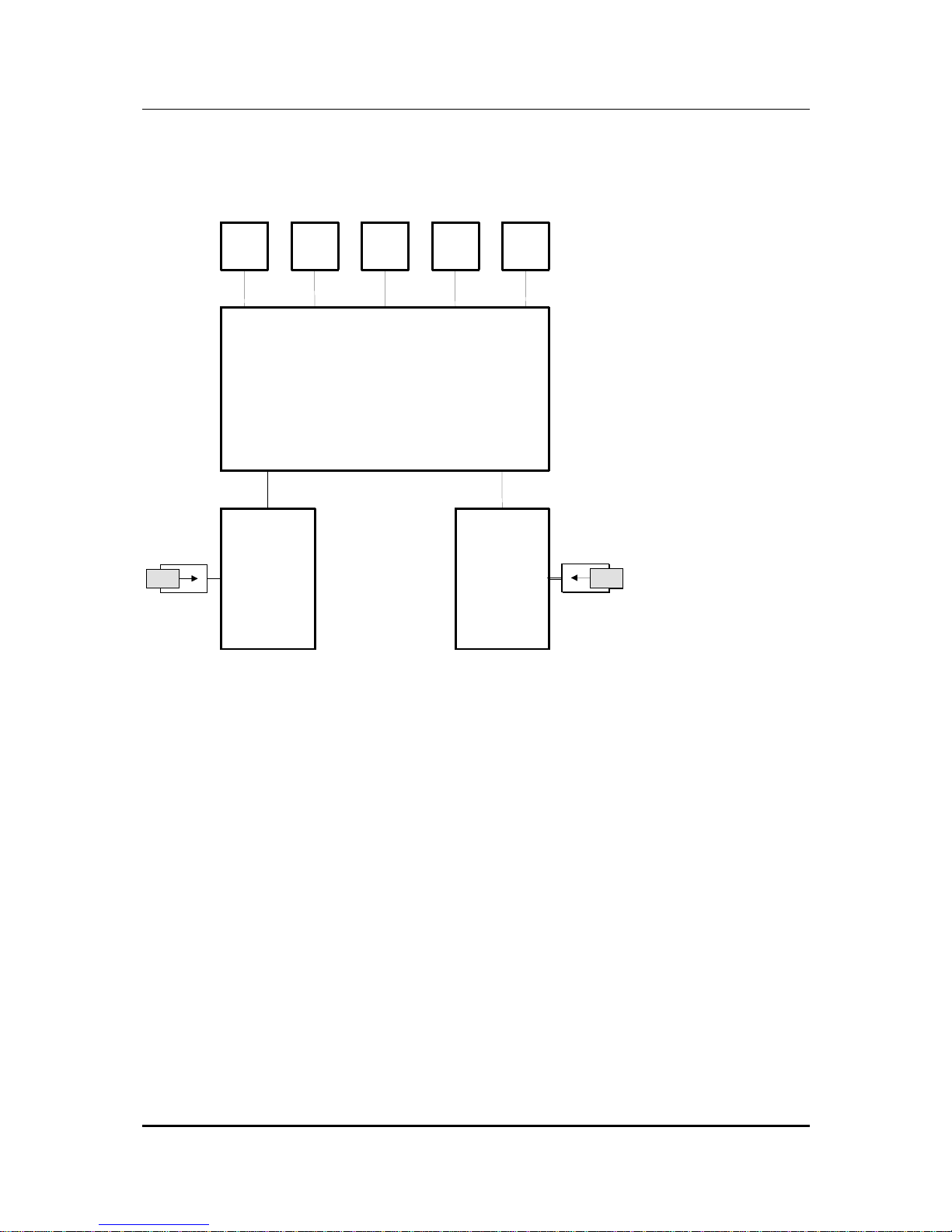
To realise the above features, a microprocessors switching has been developed
which controls the interaction of the various functional groups of coM.sat ISDN Basic.
These are illustrated in the following sketch.
USB
TE/
Sync
NT
LED DC IN
coM.s.a.t. ISDN Basic
Mainboard
GSM Module 1
SIM
SIMSIMSIMSIMSIMSIMSIMSIM
SIMSIMSIMSIMSIMSIMSIMSIMSIMSIMSIMSIMSIMSIMSIM
SIM
GSM Module 2
Figure 1: Functional Groups
coM.sat ISDN Basic
created: page: file:
16/01/09 14 coMsat ISDN Basic Manual V2.7.doc
Note Protection Mark according to DIN 34!
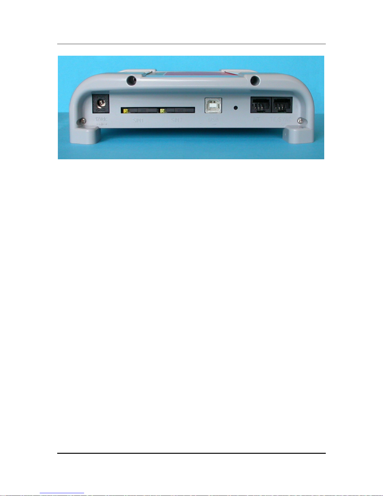
Figure 2: Front side of the coM.sat ISDN Basic
On the front side are located:
• the connector for the power supply
• 2 SIM card readers
• the connector for the USB port (USB-B)
• the jack for the NT connection (RJ-45)
• the jack for the TE connection or the synchronisation (RJ45)
coM.sat ISDN Basic
created: page: file:
16/01/09 15 coMsat ISDN Basic Manual V2.7.doc
Note Protection Mark according to DIN 34!
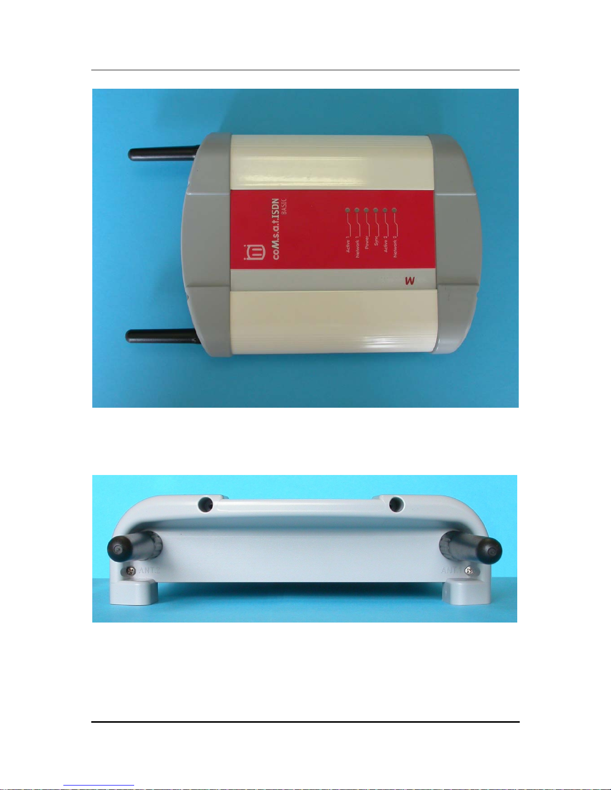
Figure 3: Top side of the coM.sat ISDN Basic
On the top side, there are the LED control indicators.
Figure 4: Rear side of the coM.sat ISDN Basic
On the rear side, there are the two RF- (SMA) connectors for the antennas, with
antennas screwed in.

coM.sat ISDN Basic
created: page: file:
16/01/09 16 coMsat ISDN Basic Manual V2.7.doc
Note Protection Mark according to DIN 34!
The connections and significance of the LED’s are labelled to prevent errors.
Before starting up the device, the SIM cards must be inserted into the provided
holders. Two 3V SIM cards are required for full channel availability, but usage with
one SIM card is possible.
To insert the SIM cards in the device, first push in the round yellow button next to the
cardholder with a blunt, thin tool and then remove the cardholder. The SIM card is
then placed in the cardholder and inserted into the card reader together with its
holder. The contact area of the cardholder must be facing the rear of the device.
Attention: When pushing in the card, ensure that it does not fall out of the cardholder
and that the card is correctly inserted in the cardholder guides. The device requires
3V SIM cards for operation!
3.1 Starting up the device
The SIM cards should be inserted into their reader slot first. Then the necessary
cables are connected: Connection to the TC system as NT or TE, a connection to the
PC's USB port on which the coMsat.exe application is installed, and finally the
antenna cables.
Note 1: The GSM modules used in the coM.sat ISDN Basic for communication via
the GSM network operate with an internal voltage of 3V. Therefore, for proper
operation, SIM cards that can still operate with a working voltage of 3V must be used.
All new SIM cards usually fulfil this requirement. If older cards (designed for a voltage
of 5V) are used, the device possibly cannot log into the network - despite input of the
correct PIN - because the SIMs cannot operate correctly at a voltage they weren't
designed for.
Note 2: When looking at the front of the device, the left-hand SIM card is assigned to
channel 1 and the right-hand card to channel 2.
Once it has been installed, the device can be switched on by inserting the power
jack. This is indicated by the green LED which is labelled “Power“.
All the relevant parameters in the device are deleted in the factory before delivering
the coM.sat ISDN Basic, so that it must be set for the individual installation.
Therefore, when installing the TA for the first time, it must be configured using the
coMsat.exe application. To do this, a USB data link must be established between the
coM.sat ISDN Basic and the PC on which the application is installed.
coM.sat ISDN Basic
created: page: file:
16/01/09 17 coMsat ISDN Basic Manual V2.7.doc
Note Protection Mark according to DIN 34!
3.2 Installation of the coMsat.exe application
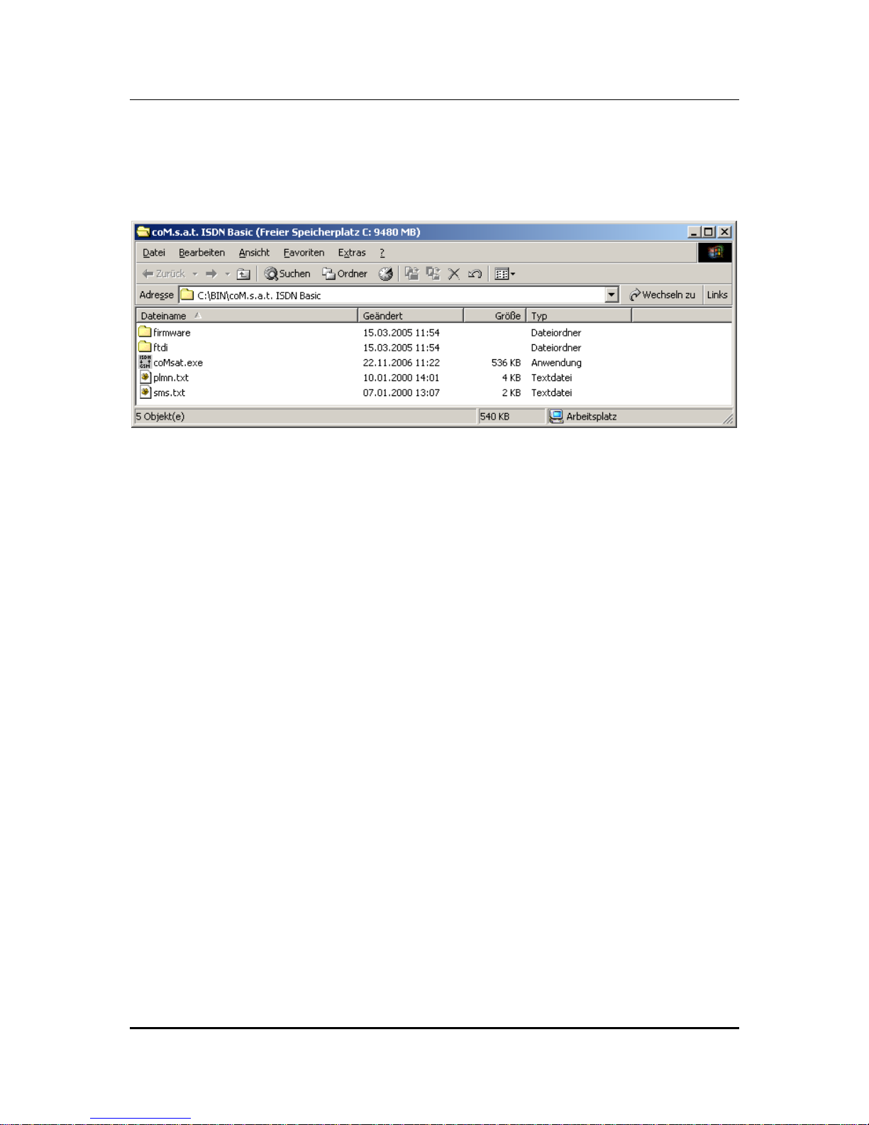
The coMsat.exe Windows® application is used to configure the coM.sat ISDN Basic.
It is copied into a suitable directory on a PC together with two text files:
Figure 5: coMsat.exe Installation
The coMsat.exe application can now be executed from this directory or via a
symbolic link that can be created manually e.g. on the desktop. A free USB port on
the PC is required for operation with the coM.sat ISDN Basic.
coMsat.exe needs a virtual COM port to access the ISDN Basic. To install it, the
current user must have administrator rights and the contents of the FTDI folder must
be stored in a suitable directory. If the ISDN Basic is attached to the PC for the first
time, the Windows® hardware assistant automatically reports a new device. It asks
for the installation files contained in the FTDI folder. After installation is completed, a
new virtual COM port has been added, e.g. COM3. This port must be used in
coMsat.exe.
The virtual device driver is supplied by Future Technology Devices International Ltd.,
the manufacturer of the USB/RS 232 converter used in the ISDN Basic. If another
driver is required, it can be obtained from www.ftdichip.com. The driver for FT232BM
must be used. The following four files in the FDTI distribution must be replaced by
those shipped with the ISDN Basic:
• FTDIBUS.INF
• FTDIPORT.INF
• FTDIUN2K.INI
• FTDIUNIN.INI

coM.sat ISDN Basic
created: page: file:
16/01/09 18 coMsat ISDN Basic Manual V2.7.doc
Note Protection Mark according to DIN 34!
3.3 Configuration of the coM.sat ISDN Basic
The coM.sat ISDN Basic is configured with the aid of the coMsat.exe Windows®
application.
After starting the application by double-clicking the application’s icon, the main
application window is opened. Several file cards are displayed which control the
various functions. These are supplemented by the typical Windows® application
menus, such as File, Connection, Configuration, Info, Firmware, Terminal,
Monitor, View, and Help and a symbol bar for quick access to the New, Open,
Save, Login, Logout, Load/Save Configuration, Load Monitor, Load Status and
About commands.
Various function groups are arranged on the file cards so that they form meaningful
units. These are:
• Interface
• ISDN Cfg
• GSM Cfg
• Routing
• Incoming Calls
• Outgoing Calls
• Fax / Data
• Statistics
• Voice
• Unconnected Calls
• Diversion
• Virtual PBX
• Clock
• Channel 1
• Channel 2
• Info
• SMS
• Diversion
• Terminal
• Monitor
Note: The statistics, voice announcement, unconnected calls and diversion functions
are only activated if there is a valid Basic Pro license (see 3.3.15). The virtual PBX
functions are only activated if there is a valid virtual PBX license (see 3.3.12.6).
coM.sat ISDN Basic
created: page: file:
16/01/09 19 coMsat ISDN Basic Manual V2.7.doc
Note Protection Mark according to DIN 34!
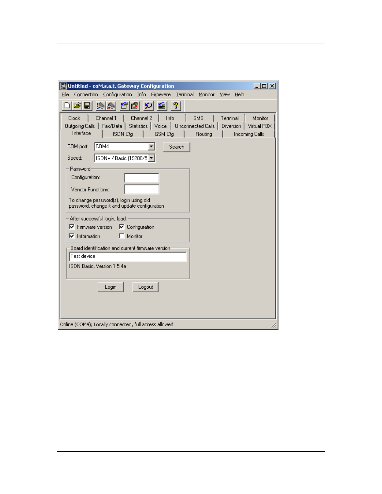
3.3.1 Interface
Figure 6: Interface
After starting the coMsat.exe application, the connection to the device is made via
the "Interface" tab. Upon clicking the tab marked "Interface" it will come to the
foreground and its contents will become visible.
The PC interface which shall be used for the data link to the coM.sat ISDN Basic is
selected using the "COM port" drop down list box. It is also possible to let the
application choose the port itself, using the "search" button. Should the application be
unable to find a connected coM.sat ISDN Basic, it will issue the message "No device
found!".

coM.sat ISDN Basic
created: page: file:
16/01/09 20 coMsat ISDN Basic Manual V2.7.doc
Note Protection Mark according to DIN 34!
Many functions require an authentication of the user. This is done by clicking on the
"Login" button also located on this tab. The authentication is removed by clicking the
"Logout" button. The termination of coMsat.exe automatically removes
authentication. Therefore explicit logout is only required if coMsat.exe remains
connected to the ISDN Basic after the user leaves it.
To prevent unauthorised persons from logging into the TA and altering the
configuration, at least the configuration password should be entered in the
“Password“ box. Each password consists of max. 19 alphanumeric characters. The
various function groups within the coM.sat ISDN Basic coMsat.exe application are
then accessible with differing protection.
Users who do not know either of these passwords can carry out all the unprotected
functions on the device. They connect to the device by calling up “Connection” on
the menu bar and calling up ”Go Online” in the menu that opens, or simply use the
desired function. The applications then connects to the coM.sat ISDN Basic. In this
mode, the device configuration can be read, but not altered. SMS can be sent and
received and any SMS received can also be read. The same procedure applies to
remote access to the device.
However, the configuration settings can only be altered by logging in with a
configuration password. Then all configuration data can be read out, amended and
resaved. The ”Vendor Functions” password makes further functional blocks
accessible, via which the various network operators can be authorised or excluded.
If a password is entered, this password is transferred to the TA together with the
configuration data. The next time the TA is logged into, the password must first be
entered in the relevant box.
A password can be deleted or altered after logging in by deleting the relevant box for
the password or entering another password. The new password is then valid after the
next update of the configuration.
On the interface tab, the user can specify additional actions after successful login.
The firmware version, the configuration of the device, the status information and the
monitor can be loaded. The first three are activated by default on every execution of
the software.
The firmware name and version (if loaded) and the user configurable device
identification are also displayed on the interface tab. The device identification is
stored in the device on updating its configuration and displayed on the interface tab
after reading the configuration. Its purpose is to allow easy recognition of different
devices in a multi-device installation.
The configuration data of one or several devices can be saved as usual in
Windows®. The files contain the configuration, the firmware ID, the device
information and the monitor contents, if these have been loaded before.
At the bottom of the coMsat.exe window there is a state bar which displays the
coM.sat ISDN Basic
created: page: file:
16/01/09 21 coMsat ISDN Basic Manual V2.7.doc
Note Protection Mark according to DIN 34!
current actions. The state of the link (online/offline) and the port of the PC via which
the data is transmitted when a link is made (e.g. “Online (COM 1)”) is displayed on
the left-hand side of the bar.
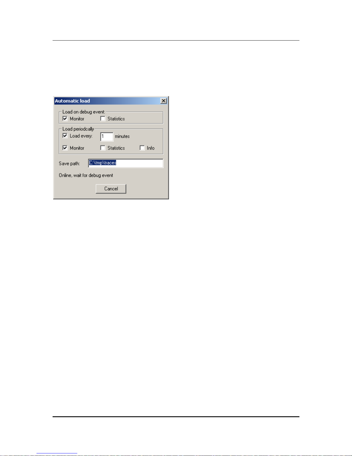
The ”Connection” menu contains another command, i.e. ”Automatic Load”. This
command opens the following dialog:
Figure 7: Automatic Load
As long as this dialog is open, coMsat.exe checks the messages from the device
and starts an automatic load if it reports a restart. It can load the monitor and the
statistics as selected by the first two options.
The load process can also be started periodically. To enable this, the option “Load
every … minutes” must be activated and the period set as desired. The automatic
can load the monitor, the statistics and the status information as selected by the
options. The statistics can only be loaded if the license for extended funktions is
available, otherwise the option is disabled.
If the automatic load is done for monitoring a long period, the load timeout should last
3 – 5 minutes in order not to loose information. If only statistics is loaded, 1 hour is
sufficient. To load the statistics, a login must be possible so the passwords must be
entered correctly. The automatic load function logs in before loading the statistics,
even if already logged in. This is done because a restart might have caused a logout
and then the statistics could not be loaded anymore.
coM.sat ISDN Basic
created: page: file:
16/01/09 22 coMsat ISDN Basic Manual V2.7.doc
Note Protection Mark according to DIN 34!
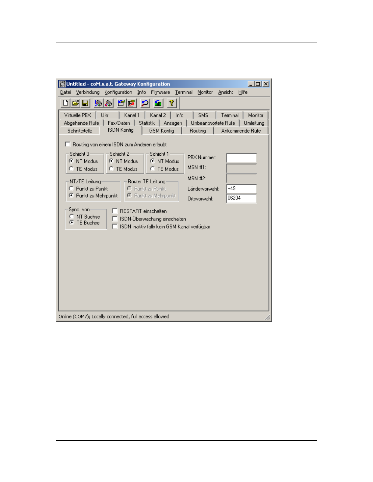
3.3.2 ISDN Configuration
Figure 8: ISDN Configuration
The settings required for operation with the telephone system are made in the "ISDN
Cfg" tab. When configuring the ISDN link, layers 1 to 3 are independently set for
operation of the coM.sat ISDN Basic in NT or TE mode.
NT-Mode operation
In this mode the device presents itself to the telephone system as the ISDN network
operator's network terminator. The connection to the coM.sat ISDN Basic is set up as
a point-to-point or point-to-multipoint connection.

coM.sat ISDN Basic
created: page: file:
16/01/09 23 coMsat ISDN Basic Manual V2.7.doc
Note Protection Mark according to DIN 34!
If the telephone system additionally has a fixed network connection and it reports too
many errors (frame slips, bit slips), a synchronisation may be necessary. These types
of errors are unimportant for voice communications. However, in mostly larger TC
systems with more elaborate trouble shooting procedures, problems can occur during
operation that can cause this “faulty“ port being switched off. This can be avoided by
synchronisation. In this case, the synchronisation input of the coM.sat ISDN Basic is
connected directly with the system port (fixed network). The synchronisation clock is
then derived from this signal.
If an optional add-on board is employed, it is possible to derive the synchronization
clock from the NT port rather than the synchronization port. The parameter field
labelled "Sync from" defines which port is used for synchronization. If the
synchronization on the NT port is selected, the connected TE device must use a
clock on that port synchronized to another source. Note: Since the presence of the
add-on board is not detected, the parameter field is always enabled in NT mode even
if the add-on board is not employed. See also chapters 4.1 and 4.3.
The PBX number entry also depends on the telephone system. Some systems do not
require an entry here. As the entry of Multiple Subscriber Numbers isn't necessary in
NT-mode, their respective boxes are inactive.
TE-Mode operation
If the coM.sat ISDN Basic is to be used in TE-mode, that is like a simple extension,
then click the corresponding radio button for layer 3. Layers 2 and 1 will automatically
be set to TE-mode. In this mode (operating on the telephone system's internal S0
bus) there is usually a point-to-multipoint connection. Therefore the line type is
automatically set to this type of connection.
It is also often necessary to identify those extensions (Multiple Subscriber Numbers 1
and 2) via which the device is identified by the telephone system. Both GSM
channels may be addressable by the same MSN if supported by the telephone
system. If at least one MSN is empty, the device accepts any called party number
and uses that number for the outgoing call. This means that the MSN is dialled via
GSM, which is usually not desired. This function is useful if there is a diversion or VIP
number programmed for each possible MSN, so that the MSN is converted into a
valid GSM number.
If used in TE-mode, as terminal equipment, no synchronisation is necessary.
Router operation
If the coM.sat ISDN Basic shall be able to route calls from one ISDN port to the
other, then activate the box labelled “Allow routing from one ISDN port to the
other”. Layers 3, 2 and 1 will automatically be set to NT-mode because this reflects
the setting of the ISDN port labelled “NT”. The line type automatically changes to
point-to-point connection. The mode of layers 2 and 1 and the line type may be
changed subsequently, but layer 3 of the NT port remains in NT mode, layers 3 to 1
of the TE port always operate in TE mode, and the line type setting applies to both
ports.
The PBX number entry also depends on the telephone system. Some systems do not
require an entry here. As the entry of Multiple Subscriber Numbers isn't necessary in
router mode, their respective boxes are inactive.

coM.sat ISDN Basic
created: page: file:
16/01/09 24 coMsat ISDN Basic Manual V2.7.doc
Note Protection Mark according to DIN 34!
The ISDN line monitoring is activated via the “Enable ISDN Watchdog” option box.
In this case, if faults are registered in the ISDN layers 1 or 2, a warm restart is carried
out approx. every 100 seconds.
The “Enable Restart” checkbox defines whether or not the coM.sat ISDN Basic
sends the telephone system a restart command after a cold start or reset. Usually
this option need not be set. It can be set to terminate any active calls after a restart of
the device, but there are also TC systems that do not react on restart messages and
thus make the coM.sat ISDN Basic inaccessible until a timeout terminates the restart
procedure.
The option “ISDN inactive if no GSM channel available” can be enabled to activate
the ISDN port (either NT or TE depending on the mode) only if at least one GSM
channel is ready for calls. Otherwise the ISDN is deactivated and a PBX can use this
information to route calls to other ports. This option is deactivated in router mode,
because otherwise it would not be possible to make calls to PSTN if no GSM channel
is available.
The country and area code are set in separate input boxes. The country code is the
international dialling prefix (e.g. “+49”). The area code is usually the prefix for phone
numbers in the same town that the TA is located and is therefore omitted when
calling a number in the same area (e.g. “06204”). Entering these numbers at this
point saves you the effort of entering them during later definitions of number lists
(e.g. Net Access Numbers).
If not otherwise specified, the ISDN Basic assumes that international calls start with
“00” (or “+”) and national calls start with “0”. These settings can be modified by
appending the correct setting to the country and area code separated with a slash
(e.g. “+1/011” as country code and “…/1” as area code for USA and Canada).
The current configuration of the coM.sat ISDN Basic can be enquired by clicking on
“Configuration“ in the menu bar and then selecting “Query“ from the menu.
Alternatively, the short cut keys
<Alt> <C>
and
<Q>
can be used or the button “Query Configuration” in the toolbar can be pushed.
After entering a new configuration or altering the current configuration, this can be
saved via the “File“ menu or can be transferred to the coM.sat ISDN Basic via the
USB data link. This is done either via “Update“ in the “Configuration“ menu or by
pushing the toolbar button “Update Configuration” or by entering the relevant keys on
the keyboard.
A configuration file that has already been stored can be loaded again using the file
menu and transferred to the device as described.
coM.sat ISDN Basic
created: page: file:
16/01/09 25 coMsat ISDN Basic Manual V2.7.doc
Note Protection Mark according to DIN 34!
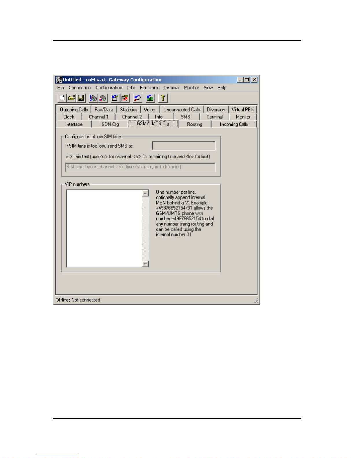
3.3.3 GSM/UMTS Configuration
Figure 9: GSM/UMTS Configuration
This page is used to configure GSM/UMTS specific options.
The coM.sat ISDN Basic implements a time based supervision of prepaid credits.
The credits themselves are dynamically programmed using the command “Set
Prepaid Time“ in menu “Info“, which is described in chapter 3.3.15. Each channel is
programmed a separate threshold, see chapter 3.3.14. If the credit falls below that
threshold, the channel is not used anymore. The GSM configuration on this page
configures additional behaviour in this case.
A GSM phone number can be programmed which shall receive an SMS if the credit
becomes low. If no number is programmed, no SMS is sent. If a number is

coM.sat ISDN Basic
created: page: file:
16/01/09 26 coMsat ISDN Basic Manual V2.7.doc
Note Protection Mark according to DIN 34!
programmed, the second input field determines which text is sent with the SMS. This
text allows three place holders:
• <ci>: Is replaced by the number of the channel with low credit
• <st>: Is replaced by the remaining time credit
• <lo>: Is replaced with the programmed threshold
The VIP number list “VIP numbers” contains GSM phone numbers that get a special
treatment. Each line contains a phone number and may also contain an MSN in the
format <GSM number>/<MSN>. The MSN may be used to define short numbers for
the members of the VIP list. If this MSN is called from any source (i.e. NT, TE or
GSM), the call is connected to the associated GSM phone number. If a call comes in
from a VIP number, the associated MSN is transmitted as calling party number in the
ISDN messages.
VIP users always have the right to dial in even if the channel’s dial in option is
switched off (“Call Default”, see 3.3.14). This allows to define a specific user group
that may dial any number while normal users only call the default extension.
VIP users also use the routing function (see 3.3.4). While normal users calling from
GSM are always connected to the PBX, VIP users may also call to PSTN or GSM
depending on the called number and the programmed routing.
If a VIP number is called, the calling party number (the number belonging to the SIM
card) is always shown to the VIP user, even if the channel in use has the option CLIR
enabled, thus suppressing the number presentation. This does not enable the use of
the return call handling in this case, because then a VIP won’t be able to use the
VPBX anymore if a return call is stored for him.
The functions of the virtual PBX are also accessible to VIP users (see 3.3.12). Thus
all GSM users contained in this list can use all functions normally available only to
PBX extensions. Therefore these phone numbers are also called virtual extensions.
Note: The device uses the country and area code settings for the GSM number so
that only one notation of a number need to be entered in the list.
coM.sat ISDN Basic
created: page: file:
16/01/09 27 coMsat ISDN Basic Manual V2.7.doc
Note Protection Mark according to DIN 34!
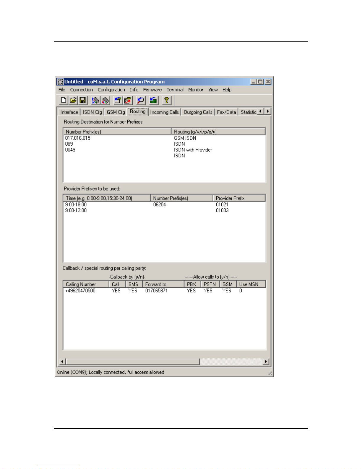
3.3.4 Routing
Figure 10: Routing

coM.sat ISDN Basic
created: page: file:
16/01/09 28 coMsat ISDN Basic Manual V2.7.doc
Note Protection Mark according to DIN 34!
3.3.4.1 Routing according to dialled number
The table “Routing Destination for Number Prefixes“ determines if GSM (with or
without provider) or ISDN (with or without provider) is to be used. Special cases also
require the setting of a routing for calls to the PBX (with or without provider).
Example:
Number Prefix Routing
017, 016, 015 GSM, ISDN
089 ISDN
0049 ISDN with Provider
ISDN
This table is parsed from top to bottom, comparing the prefix with the called number.
If the number’s first digits match the given prefix, the routing is evaluated. If “GSM” is
specified, a GSM channel is selected according to the “Net Access Numbers“
settings, optionally inserting a provider. If “ISDN” is specified, the call is routed to
PSTN, again allowing the insertion of a provider prefix, just like the specification of
“PBX” which causes a routing to the TC system. If more than one route ia specified
and the first one is not able to route to call, the second option is evaluated. If e.g.
“GSM,ISDN” is specified and there is no GSM channel available at the moment, the
call is routed to ISDN (“fallback”). If in this case only “GSM” would have been
specified, the call would be rejected.
The example above causes the following behaviour:
• All calls to typical (german) GSM numbers are routed via GSM if possible, and
via ISDN otherwise
• All calls to Munich (089) are routed via PSTN without provider prefix
• All other calls to german numbers (+49) are routed via PSTN with a provider
prefix
• All other calls are routed via PSTN without provider
In addition to numbers, the place holder “?“ can be used to specify any number. This
is especially useful if numbers can only be distinguished by their length. This applies
e.g. to internal MSNs and local area numbers. The following example assumes that
all internal MSNs are two digits long:
Number Prefix Routing
017, 016, 015 GSM
??? ISDN
?? PBX
This routing table works like this: All GSM numbers are routed via GSM. If any
number with only two digits is dialled, only the entry number 3 matches, because all
other entries require at least 3 digits. All numbers with more than two digits not
matching the first line are routed to the ISDN network.

coM.sat ISDN Basic
created: page: file:
16/01/09 29 coMsat ISDN Basic Manual V2.7.doc
Note Protection Mark according to DIN 34!
The table is split into two columns and the entries are directly edited in the list box. A
double click on an entry makes it editable. By using the “Page Up” and “Page Down”
keys, the edit field can be moved to the next or previous column. The cursor up and
down keys move the edit field one line up or down in the same column.
If the list box has the input focus but no entry is edited, the insert key allows to create
a new line above the first currently selected line. All selected lines can be deleted
using the delete key. Ctrl-C copies selected lines to the clipboard just like Ctrl-X
which also removes the lines afterwards. Ctrl-V inserts lines from the clipboard above
the first selection or at the bottom of the table if none is selected. A selection can be
removed by left click with pressed control key as usual in multiple selection list boxes.
Tab and shift-tab can be used to jump to the next or previous dialog element, as
usual.
The second column only allows to use the keys “i”, “g”, “p”, “v”, “x”, “y”, backspace,
cursor left/right and delete. “i” inserts “ISDN”, “g” inserts “GSM” and “x” inserts “PBX”
at the current insert position. “p”, “v” and “y” do the same with the option of inserting a
provider prefix. The cursor can only be positioned at the beginning and end of words.
Delete and backspace always delete complete words.
Empty lines are removed automatically before the configuration is updated.
3.3.4.2 Selection of providers by time and number
The table “Provider Prefixes to be used“ defines which provider should be used for
those numbers that are routed with provider specified in the first table. This table is
ignored otherwise.
Example:
Time Number Prefix Provider Prefix
9:00 – 18:00, 20:00 – 22:00 0241,0621 01021
9:00 – 12:00 01033
12:00 – 18:00 01013
18:00 – 20:00 01051
0:00 – 24:00 01070
This table is parsed from top to bottom, comparing the current time to the times
specified in the first column and the called number to the prefix in the second column.
An empty entry in the number prefix column matches any number. If both entries
match, the provider specified in this line is used.
The first line in this example defines a specific prefix for specific area codes. The last
line in this example causes all numbers not matching one of the entries above to be
routed using the prefix 01070.
If no entry matches, the call is rejected.
 Loading...