

Page 1
ci0052
issue 2, 2014-01-09
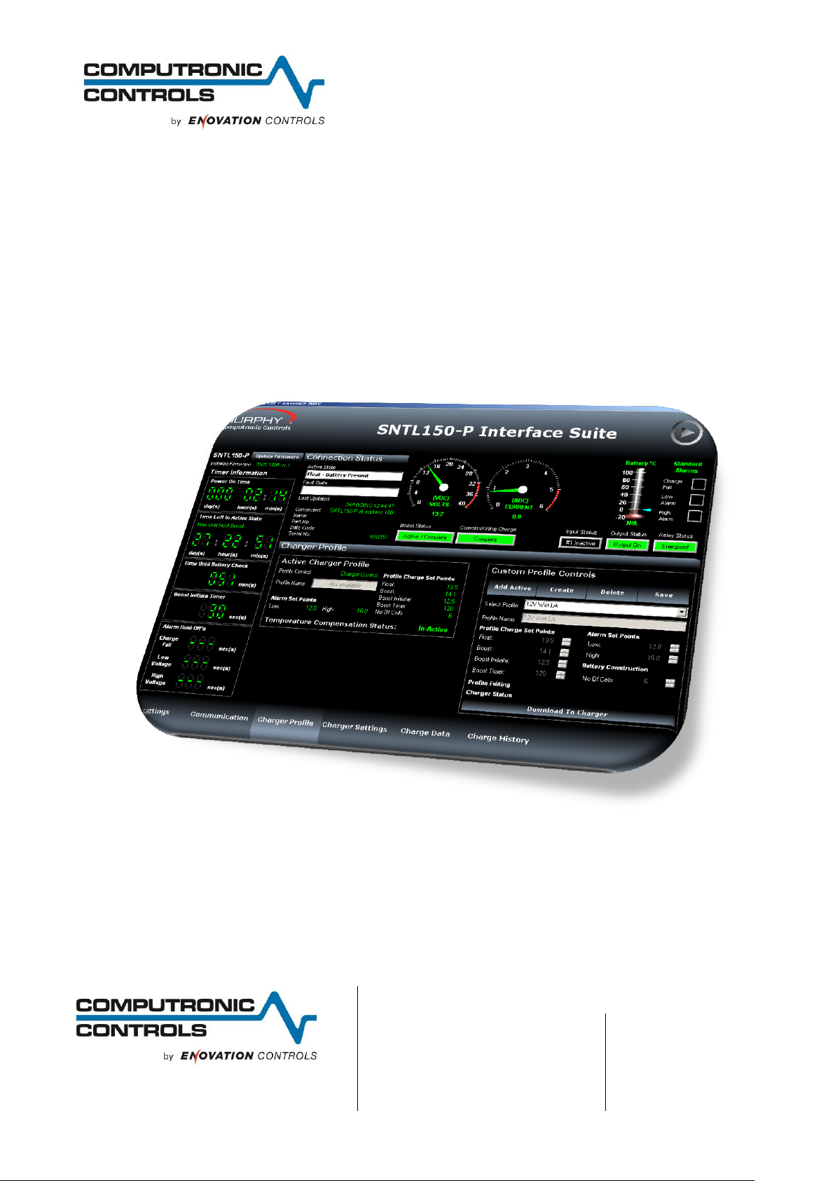
SNTL150P-PCSUITE interface suite
Configuration and Monitoring software for
Sentinel 150P automatic switch mode battery chargers
Installation and Operation Manual
41 – 46 Railway Terrace, Nechells,
Birmingham, B7 5NG, United Kingdom
Web: www.computroniccontrols.com
For sales & support, contact:
ENOVATION CONTROLS LTD.
Church Road, Laverstock,
Salisbury, SP1 1QZ, United Kingdom
Phone: +44 1722 410055
Fax: +44 1722 410088
E-mail: sales@enovationcontrols.eu
Web: www.computroniccontrols.com
www.fwmurphy.eu/computronic
ENOVATION CONTROLS
5311 S 122nd East Avenue,
Tulsa, OK 74146, USA
Phone: +1 918 317 4100
Fax: +1 918 317 4266
E-mail: sales@fwmurphy.com
Web: www.fwmurphy.com
Page 2

SNTL150P-PCSUITE installation & operation
ci0052 p2/28 issue 2 2014-01-09
Please read the following information before installing.
BEFORE BEGINNING INSTALLATION OF THIS PRODUCT:
Read and follow all product safety and installation instructions.
Please contact your Computronic Controls or F W Murphy
representative immediately if you have any questions.
In order to consistently bring you the highest quality, full featured products, we reserve the right to change our
specifications and designs at any time.
Page 3

SNTL150P-PCSUITE installation & operation
ci0052 p3/28 issue 2 2014-01-09
Table of Contents
Table of Contents 3
System requirements 5
Installation Guide 6
Getting Started 7
Environment settings 7
Connecting To Charger 8
Using the Interface Suite 9
Interface Suite Environment 10
View Level Overview 11
Active Charger Profile 11
View Level Overview 12
Time in AC failure 12
Time Charging (>500mA) 12
Time in Float Mode 12
Battery Voltage Graph 13
Charger Current Graph 13
Engineer View Overview 14
Engineer password 14
Charger Profile 14
Global Charger Settings 15
Manager View Overview 16
Manager password 16
Charger Profiles 16
Charger Settings 16
Charger Identification 16
Charge History 16
From the Setup Editor screen, a full Setup configuration can be created, deleted or modified. To create a new
Setup enter required name in the Setup Name area and complete all details as required. 17
SNTL150P Configurable Settings 18
Charger Profiles 18
Preset Charger Profiles 18
Creating Custom Profiles 19
Deleting Custom Profiles 20
Adding Current SNTL150P Profile To Software Suite 20
Applying Custom Profiles 20
Page 4

SNTL150P-PCSUITE installation & operation
ci0052 p4/28 issue 2 2014-01-09
Battery Check Routine 21
Setting Charger Current Limit 22
Boost Drop Out Current 22
Auto-Boost Period 22
Digital Input Settings (where fitted) 23
Alarm Settings (where fitted) 24
Resolving Communication Errors 25
Configuration of SNTL150-P via TTL 26
In System Programming 27
Page 5

SNTL150P-PCSUITE installation & operation
ci0052 p5/28 issue 2 2014-01-09
System requirements
The SNTL-PCSUITE is a PC-based software program for configuring and monitoring Sentinel 150P series battery
chargers. Communication between the PC and Sentinel 150P is via a USB and TTL converter.
Minimum system requirements:
1. Sentinel 150P series battery charger
2. Personal Computer (PC):
Processor: x86 (32 bit), 1GHz
RAM: 1Gb
USB port
Display: minimum resolution 1024 x 768
Operating System: Windows 7, Windows Vista, Windows XP Professional or Windows XP Home
with .NET framework 3.5 or higher
3. SNTL-PCSUITE software
4. USB / TTL converter recognised as COM port on Windows OS
5. TTL Data lead (connecting Sentinel to USB/TTL converter)
6. USB lead (connecting PC to USB/TTL converter)
Item 3 above (SNTL150P-PCSUITE software) is available on request, part number 42.70.3824: the software is
supplied by email attachment.
Item 3 is also available on CD-ROM, along with items 4 – 6, as a complete connection suite, model
SNTL150P-PCCONN, part number 42.70.3825.
Page 6
SNTL150P-PCSUITE installation & operation
ci0052 p6/28 issue 2 2014-01-09
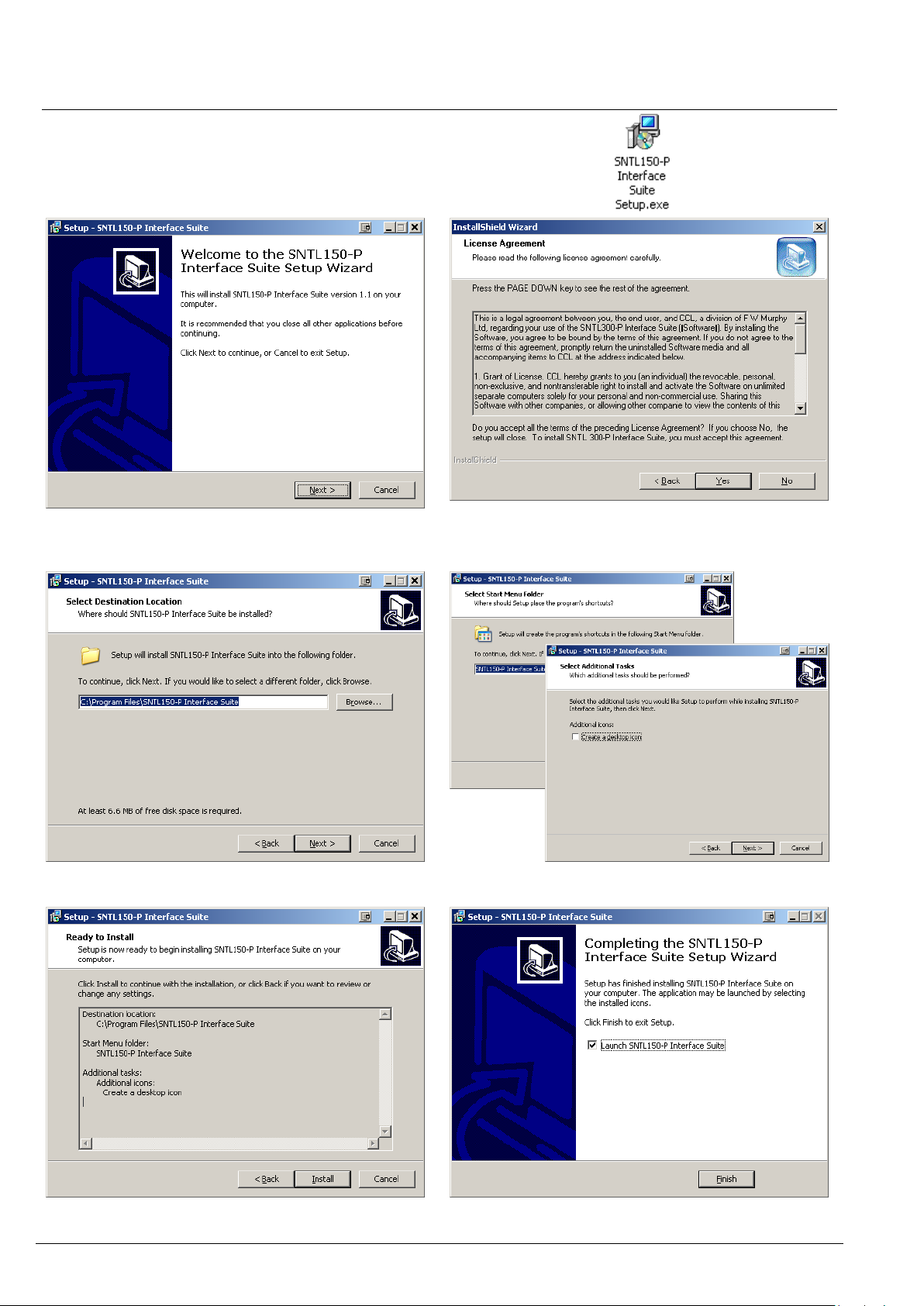
2, Select Next to continue through installation
process.
3, After viewing license agreement, select YES to
proceed
4, Select installation folder
5, Select program folder and optional desktop icon
6, Confirm installation by selecting Next
7, Installation is complete, select Finish
Installation Guide
1, Run the Sentinel 150-P Interface Suite.exe file to install software to PC
Page 7
SNTL150P-PCSUITE installation & operation
ci0052 p7/28 issue 2 2014-01-09
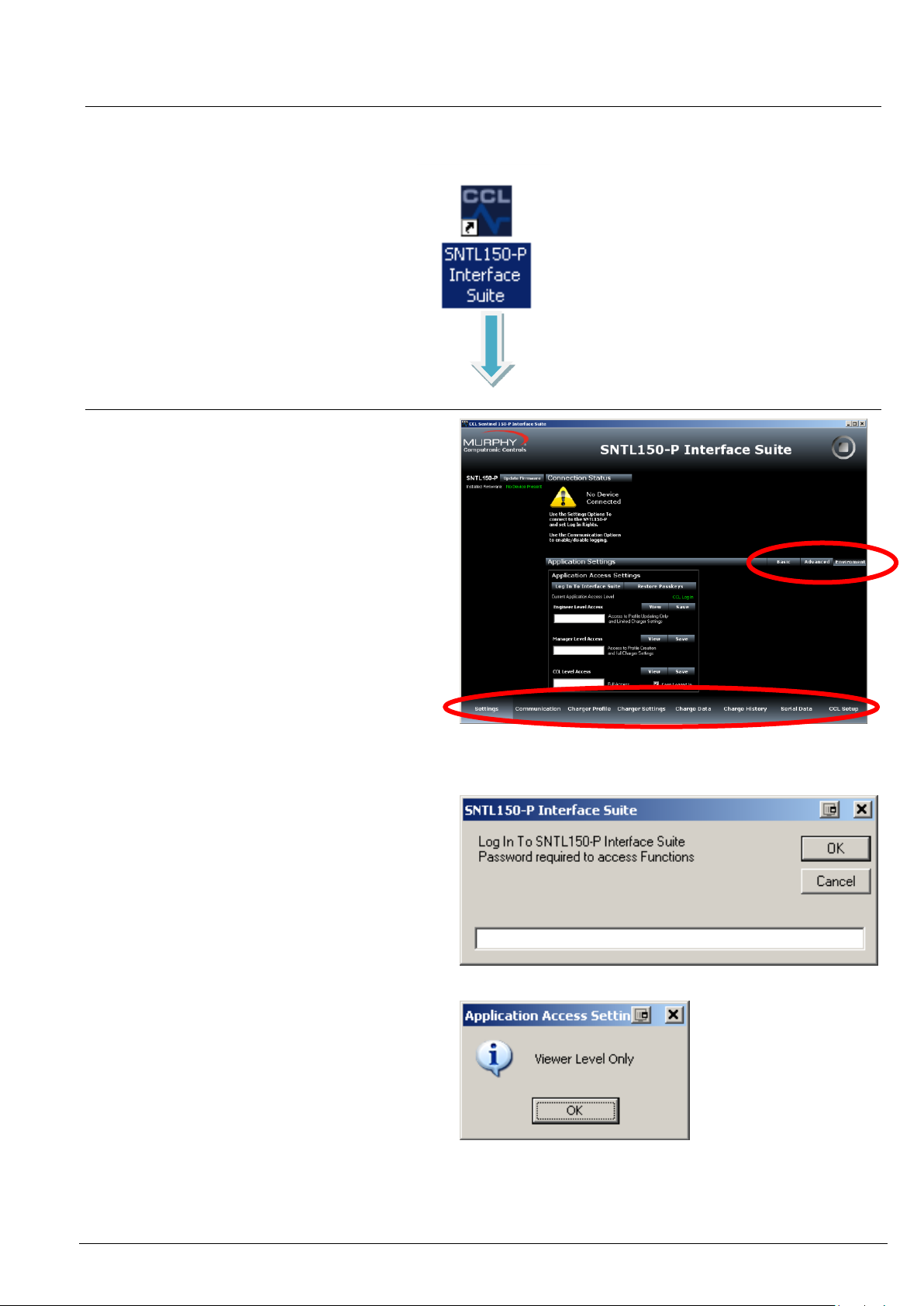
From Settings Screen, select environment from
Menu Bar and then select Log In To Interface
Suite
When asked for password, enter the supplied
password to access the appropriate level.
There are 3 modes of operation for the SNTL150P
Interface Suite
Basic View Level
Engineer Level
Manager Level
See SNTL150P Interface Suite Environment
settings section of this document for information
on paramaters available within each log in level.
Should an incorrect password be entered then the
system will state the following:
And limit access to View Level only
Screen Tab Control
Menu Bar for Screen
Getting Started
After installing SNTL150P interface suite on your PC, a desk top icon as shown below will be added. Select this to
launch the SNTL150P interface suite
Environment settings
Page 8
SNTL150P-PCSUITE installation & operation
ci0052 p8/28 issue 2 2014-01-09
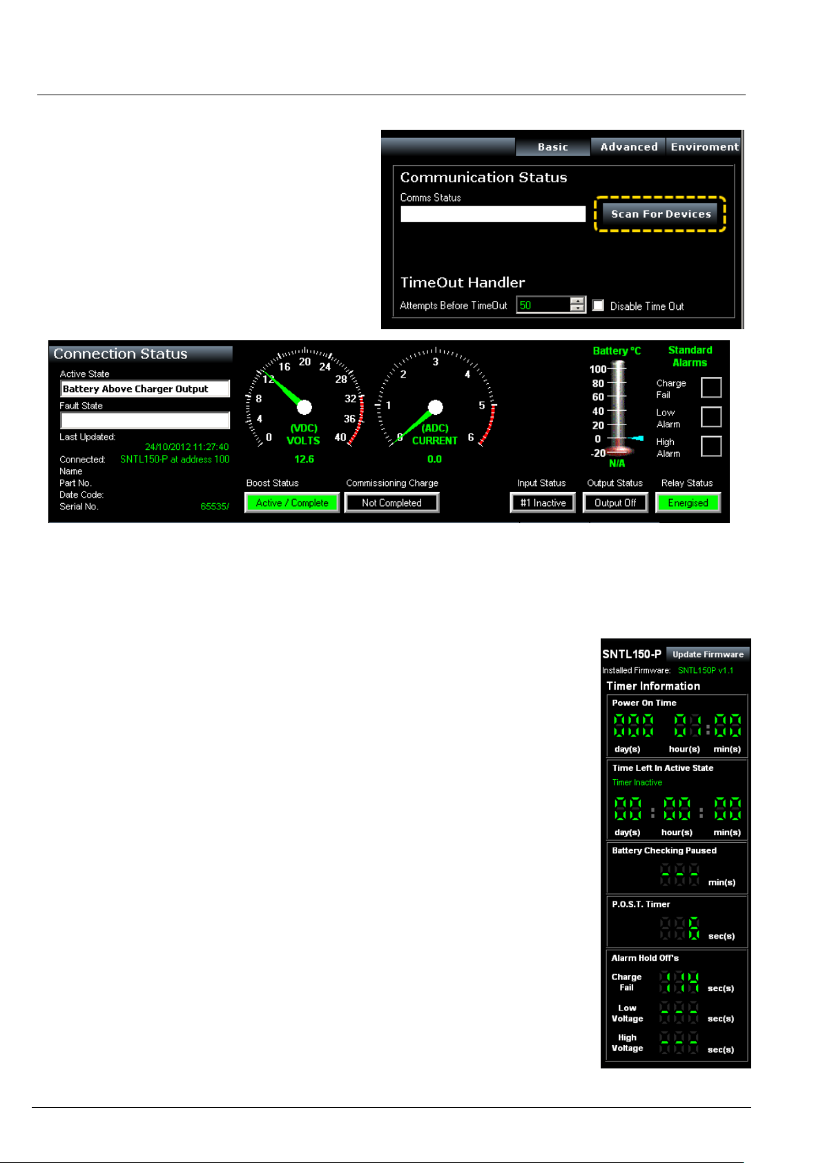
Once connected to charger and SNTL150P has
either DC or AC power, select Scan For Devices to
initiate scan.
Upon successful detection of the SNTL150P the
software suite will automatically connect and start
communicating
See resolving communication errors section (page 25) of this document should you have problems
connecting to the SNTL150P
Once communication is established with the unit, the Top & Side Status windows and
indications will become active and reflect the SNTL150P’s current condition
Top Status Window
In addition to information about voltage, output current and SNTL150P model
information, the Top Status Window provides information regarding its charging state.
Battery (°C) Thermometer - will indicate SNTL150P detected battery temperature
should a remote temperature compensation lead be connected. (Temperature is
shown in °C)
Boost Status – Will indicate if SNTL150P needs to enter its boost cycle. Indicates if
Waiting to Start, Active or Completed. Once SNTL150P terminal voltage has
increased above boost initiate voltage, then this will become green.
Commissioning Charge – When SNTL150P is first powered up, it will automatically
enter a prolonged boost extension period, factory set to 6 hours, once complete this
will become green and be marked as complete.
Input Status (if option fitted) – Shows indication of SNTL150Ps digital input
Output Status – Shows indication of SNTL150P self-resetting output protection
circuit
Relay Status (if option fitted) – Shows Fault Relay Status
Side Status Window
The firmware revision installed in the SNTL150P is displayed along with option to
update, Consult updating firmware section within this document.
The side status window will indicate information about timers on the SNTL150P.
Power On Time – Duration that the SNTL150P has been powered (AC or DC)
Time Left in Active State - How long the SNTL150P has remaining in its current
state.
Time Until Battery Check - How long before next Battery Check is performed.
P.O.S.T. Timer / Boost Initiate Timer -
Time (counting down from 30s) until boost is initiated if battery measured voltage is
below the boost initiate set point or the 6 second POST timer performed on initial
power up or after a Connection Fault
Alarm Hold Off’s – Low, High and Charge Fail alarms are held off for 2 minutes,
should the fault still be present at the end of the hold timer then an alarm will be
indicated.
Connecting To Charger
Page 9
SNTL150P-PCSUITE installation & operation
ci0052 p9/28 issue 2 2014-01-09
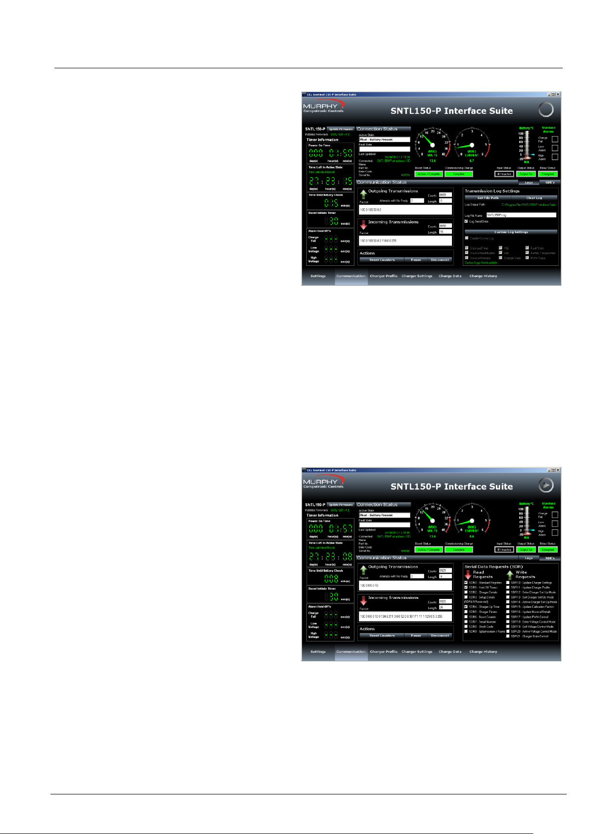
The Communication Screen
This screen shows Incoming and Outgoing
Transmissions between the PC and SNTL150P.
Reset Counters – Allows the monitored counts to be
reset on the PC software
Pause – Allows the connections to be paused,
ceasing all communications with charger until
Continue is selected
To terminate connections with SNTL150P, select
Disconnect from the Actions to ensure the Port is
correctly closed.
Warning! Failure to do so before physically
disconnecting from the SNTL150P may cause
interrupt damage to the SNTL150P requiring a full
AC/DC reset before normal operation can continue.
Transmission Log
SNTL150P Interface Suite can log all serial
transmissions. These log files can then be loaded
into the Charge Data Screen.
Set File Path - The File Path of stored log can be
selected, default is same path as installed interface
suite
Clear Log – Delete the log if already present
Log File Name – Enter a name for the log (default is
SNTL150P Log)
Note: Custom Logs can be configured to record
specific data in a csv file (TAB separated), under the
directory selected as above.
The SDR (Serial Data Request) option shows
messages queued waiting for action by software
suite.
Using the Interface Suite
Page 10

SNTL150P-PCSUITE installation & operation
ci0052 p10/28 issue 2 2014-01-09
Interface Suite Environment
There are 3 modes of operation for the SNTL150P Interface Suite
Basic View Level
Engineer Level
Manager Level
The following pages outline features and parameters available within each log in level.
Page 11

SNTL150P-PCSUITE installation & operation
ci0052 p11/28 issue 2 2014-01-09
Charger Profile screen
This provides information of the set conditions of
the SNTL150P.
Active Charger Profile
This provides information on what the SNTL150P
charger is currently configured to along with status of
temperature compensation sensor.
Charger settings screen
This provides information of the set conditions of
the SNTL150P
It shows what the various parameters of the
SNTL150P are configured to as well as alarm
conditions and actions.
View Level Overview
If no password is entered when requested or environment level not changed then the Interface Suite works in view
mode only. From this setting the following four screens are available in addition to the standard Settings &
Communication Screens:
Page 12

SNTL150P-PCSUITE installation & operation
ci0052 p12/28 issue 2 2014-01-09
Charger History screen – Charger State History
This provides an historic view of the chargers
time in various charge states as well as key
counters.
Time in AC failure
Time spent powered by DC with AC failure fault
recorded
Time Charging (>500mA)
Time spent delivering in excess of 500mA
Max Battery Temperature
SNTL150P will record the highest temperature
recorded by the Temperature Sensor (if connected)
Time Battery Missing
Time spent powered by AC with no Battery
Connected
Time in Float Mode
Time spent with charger in its float mode of operation
Time in Boost
Combination of all time spent both in SNTL150Ps
ramping to boost stages as well as Boost Extension
Periods, including commissioning charge times.
The central pie chart shows a breakdown of time spent by
SNTL150P in its 5 key charge states.
Charger History screen – Recharge History
This provides an historic view of the last 15 bulk
charges in time.
The SNTL150P will record time spent ‘ramping
the batteries to their target boost voltage.
(recorded in 10 minute blocks)
The Bar Graph Display will provide an indication of
the trend of the battery recharge time, typically as
batteries chemical makeup weakens, the bulk charge
time will decrease, as the capacity of the battery
becomes reduced.
Note: Use with caution as a guide to battery health,
as the SNTL150P will only record time spent in this
condition, but not the batteries terminal voltage at
start of charge cycle.
View Level Overview
If no password is entered when requested or environment level not changed then the Interface Suite works in view
mode only. From this setting the following four screens are available in addition to the standard Settings &
Communication Screens:
Page 13

SNTL150P-PCSUITE installation & operation
ci0052 p13/28 issue 2 2014-01-09
Charger data screen
This provides a scrolling display of the chargers
output voltage and current.
Battery Voltage Graph
This displays a record of the chargers output voltage
(VDC)
Charger Current Graph
This displays a record of the chargers output current
(ADC)
PWM Graph
This displays a record of the chargers internal PWM
output.
Selecting a position within the charge data display
will open a Log Details window which will show
specific time index, charger state, VDC, ADC and
PWM for position selected in chart.
Page 14

SNTL150P-PCSUITE installation & operation
ci0052 p14/28 issue 2 2014-01-09
Within the interface suite the following additional
settings are available:
Engineer password
Within the Settings/Environment Tab, the engineer
password can be changed or viewed
Charger Profile
From the drop down list provided a new charger
state can be selected, select item from list then
select Update to make changes
Note: SNTL150P cannot change its state whilst
performing a charger check (mains check)
From the predefined list of battery profiles a new
charger profile can be selected and downloaded to
charger
Within the charger settings screen the following additional settings are available:
Engineer View Overview
As well as the basic view screens, additional controls are now available
Page 15

SNTL150P-PCSUITE installation & operation
ci0052 p15/28 issue 2 2014-01-09
Global Charger Settings
Global Charger Settings
View Charger Slave Address
Amend Current Limit – See SNTL150P configurable settings for details
Alarm Hold Off Timer - see SNTL150P configurable settings for details
Battery Check Settings
Amend Battery Check Interval – see SNTL150P configurable settings for details
Battery Detect Voltage – see SNTL150P configurable settings for details
Battery Detect Action & Timer – see SNTL150P configurable settings for details
Battery Missing Actions & Timers – see SNTL150P configurable settings for details
Boost Settings
Boost Drop Out Current - see SNTL150P configurable settings for details
Auto-Boost Timer - see SNTL150P configurable settings for details
Commissioning Charge Timer - see SNTL150P configurable settings for details
Input & Alarm Configurations can also be set - - see SNTL150P configurable settings for details
Select Download To Charger to finalise changes
Page 16

SNTL150P-PCSUITE installation & operation
ci0052 p16/28 issue 2 2014-01-09
Within the various screens both the engineer
configuration levels are available plus the following
additional settings are now available:
Manager password
Within the Settings/Environment Tab, the manager
password can be changed or viewed
Charger Profiles
From the predefined list of battery profiles a new
charger profile can be selected and downloaded to
charger. New charger profiles can also be both
created and deleted – see SNTL150P configurable
settings for details
Charger Settings
From the Charger Settings the SNTL150P can be
reset to factory defaults for the Part Number the
charger is configured to.
Charger Identification
The SNTL150P can now be configured to have a
unique Charger Name. This appears within the
Connection Status Window.
Charge History
The SNTL150P charge history can be cleared by
selecting Reset from the Charge History Screen.
Note: Power On Time and Charging Time (>500mA)
are not resettable.
Manager View Overview
As well as the basic view screens additional controls are now available
Page 17

SNTL150P-PCSUITE installation & operation
ci0052 p17/28 issue 2 2014-01-09
Within the Charger Profile Tab an option to set the
SNTL150P up by means of a user generated part
number is available.
This allows all settings, including charger profile and
general settings to be configured in a singular
process. These setup profiles can be created,
modified and deleted from the Editor Screen.
Select Download To Charger to apply setup.
Select Edit Setup Profiles to access the Setup
editor screen.
From the Setup Editor screen, a full Setup
configuration can be created, deleted or modified.
To create a new Setup enter required name in the
Setup Name area and complete all details as
required.
Once complete select Save Setup from the menu.
The setup profile can also be exported to a .pro file.
Any previously exported .pro files can also be
imported into the Setup Editor and modified/saved
as required.
Should any details be missing or out of range. The
Setup Editor will highlight errors and prevent saving
of profile.
Once complete select Exit Editor. Any newly saved
profiles will now appear within the 1-Click Editor
panel in the main application Tab.
Note: If the connected SNTL150P does not match the
nominal voltage of the Setup Profile created then
the SNTL150P Interface will flag the error and not
download the information to the SNTL150P.
1-Click Setup Options
Page 18

SNTL150P-PCSUITE installation & operation
ci0052 p18/28 issue 2 2014-01-09
PROFILE NAME
Name of profile*
*Note: This is for local PC storage of profile, not stored
or saved by SNTL150P.
FLOAT VOLTAGE
This should be according to manufacturer
recommendations for battery type, i.e Wet Lead Acid =
2.25V/p/c = 12V Settings = 13.5Vdc
BOOST VOLTAGE
This should be according to manufacturer
recommendations for battery type, i.e Wet Lead Acid =
2.23V/p/c = 12V Settings = 14.1dc
BOOST INITIATE VOLTAGE
The voltage at which the SNTL150P Initiates Boost
Function. This should be a voltage lower than Float
voltage, typically nominal (i.e. 12V or 24V)
BOOST PERIOD
Amount of Time for Charger to remain at Boost Voltage
before returning to Float
LOW ALARM VOLTAGE
Low Alarm Voltage Setting
HIGH ALARM VOLTAGE
High Alarm Voltage Setting
NUMBER OF CELLS
Used for correct calibration of Temperature
Compensation. If, such as in the case of Power Supply
modes, no temperature compensation is required enter
‘0’
SNTL150P Configurable Settings
Charger Profiles
Depending upon access password entered, the selection or creation of new charger profiles is available. The
configurable fields are as follows:
Preset Charger Profiles
The SNTL150P contains an inbuilt list of the most common type of batteries used, these can be selected from the
drop down menu:
12V Wet Lead Acid
12V Calcium Calcium
12V Lead Acid Antinomy
12V VRLA – AGM
12V VRLA – Gel
10 Cell NiCd
18 Cell NiCd
20 Cell NiCd
24V Wet Lead Acid
24V Calcium Calcium
24V Lead Acid Antinomy
24V VRLA – AGM
24V VRLA – Gel
Page 19

SNTL150P-PCSUITE installation & operation
ci0052 p19/28 issue 2 2014-01-09
Select Create this will allow entry of charger
profile parameters as outlined above.
Enter all parameters as required
Once complete, select Save
*Please see notes below for rules on charger
profiles.
The newly created custom profile will now appear
in the drop down list of profiles
Parameter
12V Models
24V Models
Boost Initiate Setting
10V / 20Vdc- Float Setting within correct scale
Float Setting
10V – 17Vdc
20V-32.0Vdc
Boost Setting*
*To disable boost tick boost disabled option
10V – 17Vdc
20V-32.0Vdc
Creating Custom Profiles
Only available in Manager Mode
Rules & Limits of Profile Creation:
Note: Mixing voltage thresholds (17V) on a singular profile will also create an error. For example, Float cannot be
13.5Vdc and Boost be >17Vdc.
Page 20

SNTL150P-PCSUITE installation & operation
ci0052 p20/28 issue 2 2014-01-09
Select the custom profile from the drop down list of
profiles, once selected, as shown, select delete. The
entry will be removed and the first profile within the
list will be shown.
Note: Only custom profiles can be deleted from the
list.
Adding Current SNTL150P Profile To
Software Suite
Once SNTL150P is connected to the Interface Suite,
the current profile can be stored on the PC. Select
Add Active to save this profile. It will be added
under the profile name of “SNTL150-P Downloaded
Profile”
Select the profile you wish to apply to the SNTL150P
Charger from the drop down menu
Once profile is selected, select download to
charger
Notes: If the profile selected is not suitable for the
charger connected to, i.e. 24V profile on a 12V unit
the shown dialogue screen will appear warning of
this error. Profile will not be downloaded.
Deleting Custom Profiles
Applying Custom Profiles
Page 21

SNTL150P-PCSUITE installation & operation
ci0052 p21/28 issue 2 2014-01-09
The Battery check process reduces the output of
charger to nominal voltage and validates terminal
voltage.
During this battery check it will report Checking
Battery in the Active State window.
If no battery is detected, or battery voltage is less
than the configured Battery Detect Voltage then it
reports Battery Missing in the Fault State window.
The SNTL150P Performs a battery check at the
following instances:
On AC Power Up, before entering boost mode
of operation
After Completing a Boost Cycle
Every 1 minute if battery presence is not
detected
Every period of minutes as defined by Global
Charger Settings whilst in Float Mode of
Operation
Once charger is in Float mode, the charger performs
a battery check in accordance with the Battery Check
Period setting as configured in Global Charger
Settings
To change the interval time of the battery check
routine, enter required time in minutes into Battery
Check Period and select Download To Charger to
SNTL150P
Note: When download a new interval time, the
changes will take place immediately. To disable
battery checking, enter “0” as Battery Check Period
and update charger.
The SNTL150P can also be configured to turn its output
off for up to 30 seconds when performing battery
check. After this period has elapsed, the SNTL150P will
measure its own DC supply voltage and in accordance
with Battery Detect Voltage will report Battery
Missing status.
Should the SNTL150P report a battery check, it will
continue checking every 1 minute for battery until
fault has cleared. Once a battery is detected it will
revert to Battery Check Period time
During a Battery Missing Alarm the SNTL150P will
behave in accordance with the parameters set in
Battery Missing Action. The SNTL150P’s output can be
turned off, or set to a specified level.
Battery Check Routine
Page 22

SNTL150P-PCSUITE installation & operation
ci0052 p22/28 issue 2 2014-01-09
The SNTL150P maximum output current can be
limited to a value as set within the Current Limit field
in Global Charger Settings.
Note: If battery voltage is below minimum charger
output voltage (typically 10V on a 12V unit and 20V on
24V unit) then the SNTL150P will be limited by
demands from battery and hardware current limit
control (5A)
Boost Drop Out Current
The alarm output can be set to hold off fault reporting
for up to a maximum of 240 seconds (4 mins).
The SNTL150P will terminate its Boost cycle if the
output current has dropped below a preset level. This
prevents needless battery gassing and temperature
rise, once the battery is fully charged.
Configurable Boost Drop-Out Current between 0 and
5amps to a 0.1A resolution, the option to disable this
feature can be done by ticking the checkbox marked
“Disable Boost Drop Out On Current”
The SNTL150P employs a configurable option to allow
an auto-boost cycle to occur without the need to
manually engage it. Should the charger not have
recorded a boost cycle happening within a given
period, it exercises the batteries, elevating their
terminal voltage, recombining the partly separated
water and strong sulphuric acid within the cells,
preventing build up on the battery plates and
maintaining battery life and performance
Enter required Auto-Boost Period in Days, 0 (Disable) -
31.
Setting Charger Current Limit
Boost Drop Out Current
Auto-Boost Period
Page 23

SNTL150P-PCSUITE installation & operation
ci0052 p23/28 issue 2 2014-01-09
The digital input can be configured to make SNTL150P
behave in a given manner.
The following options are available:
Return To Float Mode
Single Input Action, forcing charger back to Float.
(Once actioned, the input needs to be released and retriggered for it to act again)
Ramp To Boost
Single Input Action, forcing charger through a full boost
cycle
Boost Extension
Single Input Action, forcing charger into a timed boost
extension cycle
Perform Battery Check
Single Input Action, forces SNTL150P to perform a
battery check
Reduce to Nominal Voltage
Held Input Action, reduces the output voltage of
SNTL150P to its nominal value. (12/.24V) SNTL150P
will remain at this level unit either:
Input is released
A Short Circuit / Reverse Polarity Fault occurs
Turn Output Off
Held Input Action, turns the output off from the
SNTL150P. SNTL150P will remain in this condition until
either:
Input is released
A Short Circuit / Reverse Polarity Fault occurs
Digital Input Settings (where fitted)
Page 24

SNTL150P-PCSUITE installation & operation
ci0052 p24/28 issue 2 2014-01-09
The alarm output can be configured to make
SNTL150P behave in a given manner.
Of the 8 indicated reported faults, any
combination can be ticked to cause the
SNTL150P to de-energise relay in fault
condition.
Apply changes and Download Global Settings
Note: Should only High Alarm be configured to
alarm, then SNTL150P will inverse the logic of
the relay and cause it to energise on fault.
This prevents mi-interpreted readings from
the alarm.
Alarm Settings (where fitted)
Once all settings have been made as per requirements, select Download To Charger to update SNTL150P.
Page 25

SNTL150P-PCSUITE installation & operation
ci0052 p25/28 issue 2 2014-01-09
If a valid COM port setting has not been entered the
following errors will occur. Ensure a COM port is
selected from the drop down list.
Ensure the COM port selected is correct for the
USB/TTL converter connected between SNTL150P
and PC.
Baud Rate is 9600 as default for the SNTL150P
charger.
Under settings – Advanced settings set the
following parameters.
Network Address (Minimum) 100 (cannot be
changed)
Network Address (Maximum) Up to 250
Note:
The Higher the number the longer it will take for the
system to scan node addresses, if possible limit the
Maximum address number to as low as possible.
Currently the SNTL150P has a fixed address of 100.
These settings have no effect.
Communication Settings
Scan Rate – Sets the scan rate interval between the
Interface suite and the SNTL150P. This enables
reduced entries in the log file when capturing long
charge logs.
(Adjustable between 1ms and 60s)
Message Break - Controls the end of message time
out from the SNTL150P.
(Adjustable between 0ms and 500ms)
Note: Adjusting the Message Break Time may result
in failure of the SNTL150P to communicate.
USB Com Port must match the device settings
within the Windows OS they can be found under
Control Panel/System/Hardware/Device Manager
and should be listed under Ports (COM & LPT)
Resolving Communication Errors
Page 26

SNTL150P-PCSUITE installation & operation
ci0052 p26/28 issue 2 2014-01-09
Register
SNTL150P Function
Scaling
40011
Float voltage
Voltage X 10
40012
Boost voltage
Voltage X 10
40013
Boost initiate voltage
Voltage X 10
40014
Boost period
Minutes
40015
Low alarm voltage
Voltage X 10
40016
High alarm voltage
Voltage X 10
40017
(High Byte) Number of cells
Cells X 1
(Low Byte is reserved, the value stored
must be read and then rewritten to
SNTL150P when updating profile)
Configuration of SNTL150-P via TTL
In order for customers to transmit their own remote profiles to the SNTL150P, the following protocol must be
used:
Packet must be sent in the following format
[Byte1] Node Address must be that of the charger (Preset of 100)
[Byte2] Write Multiple Registers (0x10)
[Byte3] Starting Address (High Byte)
[Byte 4] Starting Address (Low Byte)
[Byte 5] Number of Registers {High Byte)
[Byte 6] Number of Registers (Low Byte)
[Bytes 7 – 20] Data as per below
Register start address = 11
Number of points = 7
The confirmation message back will match Bytes 1 – 6 of transmitted message. Changes are made instantly.
Page 27

SNTL150P-PCSUITE installation & operation
ci0052 p27/28 issue 2 2014-01-09
From side status window, select update
firmware
From the in-system programming tool
select file to download using Load File
Dialogue
If the SNTL150P is powered up and
connected the Interface Suite, after
selecting Program the SNTL150P will
automatically reset ready to accept new
program. Should the SNTL150P not be
powered follow instructions on screen to
turn on charger
Whilst programming the charger
firmware the SNTL150Ps green LED will
flash rapidly as the data is downloaded.
Selecting Exit ISP will abort the process.
Once complete, the interface suite will
automatically close the ISP and connect
to the SNTL150P
In System Programming
Updating your firmware
Install the SNTL150P Interface Suite as per the instructions contained with the manual.
Once installed follow standard Connecting To Charger section of manual to ensure charger connects correctly to
software suite. Once successfully connected, follow instructions below.
Page 28

SNTL150P-PCSUITE installation & operation
ci0052 p28/28 issue 2 2014-01-09
41 – 46 Railway Terrace, Nechells,
Birmingham, B7 5NG, United Kingdom
Web: www.computroniccontrols.com
For sales & support, contact:
ENOVATION CONTROLS LTD.
Church Road, Laverstock,
Salisbury, SP1 1QZ, United Kingdom
Phone: +44 1722 410055
Fax: +44 1722 410088
E-mail: sales@enovationcontrols.eu
Web: www.computroniccontrols.com
www.fwmurphy.eu/computronic
ENOVATION CONTROLS
5311 S 122nd East Avenue,
Tulsa, OK 74146, USA
Phone: +1 918 317 4100
Fax: +1 918 317 4266
E-mail: sales@fwmurphy.com
Web: www.fwmurphy.com
 Loading...