

Page 1
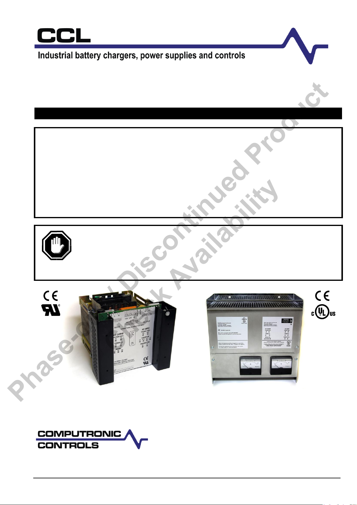
Guardian series
UL/CSA Approved Automatic Battery Chargers
INSTALLATION AND OPERATION
THIS MANUAL REFERS TO THE FOLLOWING MODULES
G1501210
G3001220
G3002410
G6002420
EG1501210
EG3001220
EG3002410
EG6002420
For safe and correct use of these chargers, read and save the safety
information that precedes the installation and operation instructions.
This guide contains 8 pages (including this one). If any pages are missing,
contact the battery charger supplier or manufacturer for replacement
documentation.
Guardian, open frame (G series)
Enclosed Guardian (EG series)
A division of Frank W Murphy Ltd.
41 – 46 Railway Terrace, Nechells, Birmingham, B7 5NG, United Kingdom
tel: +44 121 327 8500
fax: +44 121 327 8501
email: sales@computroniccontrols.com
web: www.computroniccontrols.com
Phase-out / Discontinued Product
Check Availability
CCL Guardian series installation and operation ci0003 issue 4 2014-05-06 p1/8
Page 2

IMPORTANT SAFETY INFORMATION – READ AND SAVE THESE INSTRUCTIONS
This manual contains important safety and operating instructions for models G150, G300, G600, EG150, EG300
and EG600.
Do not expose the battery charger to rain, snow or wet environments.
The use of any attachment not recommended or sold by the battery charger manufacturer may result in risk of fire,
electric shock or injury to persons.
Do not operate charger if it has received a sharp blow, been dropped, or otherwise damaged in any way: return to
supplier.
Do not disassemble the charger: return to supplier when service or repair is required. Incorrect re-assembly may result
in a risk of electric shock or fire.
WARNING – RISK OF EXPLOSIVE GASES
WORKING IN THE VICINITY OF A LEAD ACID BATTERY IS DANGEROUS. BATTERIES GENERATE EXPLOSIVE
GASES DURING NORMAL BATTERY OPERATION.
To reduce the risk of battery explosion, follow these instructions and those published by the battery manufacturers and the
manufacturer of any equipment you intend to use in the vicinity of the battery. Review cautionary marking on these
products and any attached equipment.
PERSONAL PRECAUTIONS.
(i) Someone should be within range of your voice or close enough to come to your aid when you work near a lead-acid
battery.
(ii) Have plenty of fresh water and soap nearby in case battery acid contacts skin, clothing or eyes.
(iii) Wear complete eye protection and clothing protection. Avoid touching eyes whilst working near batteries.
(iv) If battery acid contacts skin or clothing, wash immediately with soap and water. If acid enters eyes, immediately
flood eyes with running cold water for at least 10 minutes and get immediate medical attention.
(v) NEVER smoke or allow a spark or flame in vicinity of battery.
(vi) Be extra cautious to reduce risk of dropping a metal tool on to the battery. It may spark or short-circuit the battery or
other electrical part that may cause explosion.
(vii) Remove personal metal items such as rings, bracelets, necklaces and watches when working with a lead-acid
battery. A lead–acid battery can produce a short-circuit current high enough to weld a ring or the like to metal, causing
a severe burns.
(viii) Use the charger only for charging batteries as stated on the charger. Do not use the battery charger for charging
dry-cell batteries that are commonly used with home appliances. These batteries may burst and cause injury to persons
and damage to property.
(ix) NEVER CHARGE A FROZEN BATTERY
PRIOR TO INSTALLATION /COMMISSIONING
Clean battery terminals. Be careful to keep corrosion from coming into contact with eyes.
Add distilled water in each cell until the battery acid reaches a level specified by battery manufacturer. This helps purge
excessive gas from the cell. Do not overfill. For a battery without cell caps, carefully follow manufacturer’s recharging
instructions.
Study all battery manufacturer’s specific precautions, such as removing or not removing cell caps while charging and
recommended rates of charge.
Determine the voltage of battery by referring to engine manual and ensure this matches the charger’s output voltage.
CHARGER LOCATION AND CONNECTION
Never place the charger directly above battery being charged: gases from the battery will corrode and damage the
charger.
Never allow battery acid to drip on to the charger when reading specific gravity or filling battery.
Do not operate the charger in a closed-in area or restrict ventilation in any way.
The battery charger should be connected to a grounded, metal, permanent wiring system; or an equipment–grounding
conductor should be run with circuit conductors not connected to equipment-grounding terminal on the battery charger.
Connections to the battery charger should comply with all local codes and ordinances.
G150, G300 & G600 – these battery chargers should be installed so that they are not likely to be contacted by people.
EG150, EG300 & EG600 – the AC wiring should be independent of the DC and alarm wiring. Use 2x 2.5mm (total wire
Ø=5mm²) or larger wire for DC (charger to battery) leads. Use 2.5mm² or larger for input and ground connections.
For safe and correct use of the charger, follow the following steps. Should you have any problems or the unit does not
function as expected, consult our troubleshooting guide at the end of these instructions.
Visually inspect unit for any signs of damage, caused by transport or storage.
Mount the charger as outlined above, paying attention to ambient temperature.
Ensure the mains AC supply is isolated, and ensure the correct rated input voltage before connection.
Ensure the charger is earthed at the marked earth stud.
Check batteries in accordance with the manufacturer’s guidelines.
Check that the charger is correct for battery type and voltage.
Connect the charger to the batteries, observing correct polarity and ensuring a secure and tight connection.
Switch on charger at the mains AC supply.
Phase-out / Discontinued Product
Check Availability
CCL Guardian series installation and operation ci0003 issue 4 2014-05-06 p2/8
Page 3

BEFORE BEGINNING INSTALLATION OF THIS PRODUCT
Disconnect all electrical power to the charger
Make sure the charger cannot operate during installation
Follow all safety warnings of the battery manufacturer
Read and follow all installation instructions
WARNING
WARNING: Guardian battery chargers contain
no user serviceable parts, and should be
returned to the supplier in the event of failure.
No attempt should be made to repair the
charger. Any attempt to do so may invalidate
warranties, cause damage to the charger and
equipment, and result in serious personal injury.
GENERAL INFORMATION
Please read the following before installing. A visual inspection of this product for damage during shipping is
recommended before installation. It is your responsibility to ensure that qualified mechanical and electrical
technicians install this product. Failure to follow the recommended installation instructions will invalidate the
product warranty. If in doubt, please contact your local Computronic representative.
Product specification
power supply:
operating voltages
operating frequency
110 – 120 VAC ±6% or
230 VAC ±10% (specify)
50 or 60 Hz (specify)
DC charge output:
nominal voltage
12 or 24 V DC
float / boost voltages
see table below
maximum current limit:
(E)G150-12V, (E)G300-24V
(E)G300-12V, (E)G600-24V
10 A
20 A
voltage ripple
< 1%
alarm outputs:
charge fail, low volts &
high volts relays
SPDT volt free contacts
contact rating
1A @ 30 V DC (resistive load)
general:
operating temperature
-10 to +55°C
dimensions
see ‘dimensions/assembly’ overleaf
weight
see ‘dimensions/assembly’ overleaf
EMC emission / immunity
EN61000-6-4 / EN61000-6-2
Output calibration
Battery type
float volts
(V DC)
boost volts
(V DC)
12V
Vented lead acid (6 cells)
13.5
14.1
Calcium-Calcium (6 cells)
13.8
15.6
VRLA, AGM (6 cells)
13.5
14.4
VRLA, Gel (6 cells)
13.5
13.8
NiCd (10 cells)
14.1
14.5
24V
Vented Lead acid (12 cells)
27.0
28.2
Calcium-Calcium (12 cells)
27.6
31.2
VRLA, AGM (12 cells)
27.0
28.8
VRLA, Gel (12 cells)
27.0
27.6
NiCd (18 cells)
25.6
26.1
NiCd (20 cells)
28.2
29.0
Note: Calibration figures at 20 deg C. Output voltage automatically
decreases by 3mV per cell per 1°C increase in temperature.
Phase-out / Discontinued Product
Check Availability
Description & operation
The Guardian range provides automatic, current limited
and voltage controlled charging of vented lead acid, sealed
lead acid or NiCd batteries. The units may be
used in a wide range of industrial charging applications,
including standby engines, pumps and generators.
Each charger consists of a transformer, rectifier and
thyristor control circuit. The Guardian range is available as
either an open frame module for mounting in an enclosed
panel, or as a wall-mounted enclosure with DC charge
ammeter and voltmeter. (Note: In the event of no AC supply
to the charger, the voltmeter displays the DC voltage of the
battery or connected DC equipment.)
Electrical connection of the AC supply, battery and
(boost/alarm) control circuits is via spring-clamp terminals.
(For more information on these terminals, see Computronic
Controls Product Change Ref: CCL PC Release 1 – April
2003)
Float charge operation
In normal charging mode, the Guardian maintains the
battery at a pre-calibrated float voltage (see table right),
while supplying any additional DC load up to the specified
current limit (see Specification right).
When fully charged, a battery will only accept the charge
required to replace internal losses (approx. 1mA per AH of
battery). E.g. for a system with a 1 Amp standing load and a
fully charged 50 AH lead acid battery, Guardian will typically
supply 1.05 Amps.
Auto boost (equalising) operation
Auto boost operation gives a temporary increase in output
voltage (see table right), equalising the charge between
cells and maximising battery capacity and service life.
Once the batteries have reached the boost voltage level,
Guardian automatically reverts to its normal float charge
mode, preventing battery over-charge and gassing.
Auto boost is triggered automatically when the battery falls
below a preset voltage. An Auto Boost cycle can also be
manually initiated (regardless of battery voltage) by linking
two ‘boost’ terminals, e.g. via a panel switch or push-button.
enabled, output voltage decreases as ambient temperature
increases at a rate of 3mV/°C/cell (see calibration table
above for figures at 20°C).
Alarm outputs
Guardian provides 3 x NFPA110 compliant alarm relay
outputs: battery low volts and battery high volts (each with a
120 sec delay), and charge fail.
Warranty and servicing
Guardian chargers are supplied with a 2 year warranty on
parts and workmanship.
Temperature compensation
For both lead acid and NiCd batteries, the optimum charge
voltage varies with ambient temperature. On all Guardian
models, circuit board links allow output compensation to be
disabled, or enabled with an on-board temperature sensor,
or enabled with a remote sensor (RTC option, with 3 metre
lead for mounting on or near the battery). With this feature
CCL Guardian series installation and operation ci0003 issue 4 2014-05-06 p3/8
Page 4

DIMENSIONS AND ASSEMBLY
CAUTION: When handling chargers, care should be taken not to place excessive weight or strain on either the
heatsink, circuit boards, transformer or connecting wires. The units should be handled by the transformer
frame (open frame models) or steel enclosure (enclosed models). Care should also be taken not to handle
static sensitive components on the circuit board.
OPEN FRAME MODELS:
G150, G300, G600
X
Y
W2
D
W1
H1
H2
TOP VIEW
AC supply
earth stud
fuse F1, AC supply
SIDE VIEW
front
front
up
BACK (FIXING PLATE) VIEW
4 x fixing slots, 6mm
G150, G300
series
G600
series
Overall:
W1
152mm / 5.98”
152mm / 5.98”
H1
125mm / 4.92”
142mm / 5.59”
D
170mm / 6.69”
220mm / 8.66”
Fixing plate:
W2
125mm / 4.92”
130mm / 5.12”
H2
110mm / 4.33”
130mm / 5.12”
X
70mm / 2.76”
95mm / 3.74”
Y
92mm / 3.62”
110mm / 4.33”
Weight
7.0 Kg / 15.4 lb
12.5 Kg / 27.5 lb
These chargers are designed for mounting on a vertical
facia or plate inside a control panel or housing. For safe
heat dissipation, mount the product in the orientation
shown with a minimum air-gap clearance of 40mm
above/below and 25mm at sides. Consideration must
be given to ventilation for proper heat dissipation.
4 chassis slots (Ø 6mm) are provided for mounting.
Ensure that the mounting studs/bolts/nuts/screws
adequately support the charger weight, and are tightened
sufficiently to not to become loose during normal use
(e.g. due to engine/equipment vibration).
WALL MOUNTED ENCLOSURE MODELS:
EG150, EG300, EG600
2 x fixing slots, 6mm
2 x fixing holes, 6mm
up
hinged
sections
X
FF
FF
A V
W
SIDE VIEW
FRONT VIEW
D1
D2
Y
H1
H1
H2
H3
EG150, EG300
series
EG600
series
Overall:
W
275mm / 10.83”
335mm / 13.19”
H1
280mm / 11.02”
310mm / 12.20”
H2
75mm / 2.95”
85mm / 3.35”
H3
90mm / 3.54”
100mm / 3.94”
D1
125mm / 4.92”
145mm / 5.71”
D2
190mm / 7.48”
210mm / 8.27”
Fixing holes:
X
172mm / 6.77”
223mm / 8.78”
Y
255mm / 10.04”
285mm / 11.22”
Weight
10.0 Kg / 22.0 lb
17.5 Kg / 38.5 lb
These chargers are designed for wall or frame mounting
in the orientation shown above, with enclosure air vents
uppermost. For safe heat dissipation, allow a minimum airgap clearance of 40mm above/below and 25mm at sides.
Adequate consideration should be given to ventilation for
proper heat dissipation.
Mounting is via the enclosure back-plate, using 2 slots
(Ø 6mm) on the back-plate lower edge and 2 holes
(Ø 6mm) on the upper edge. Ensure that the mounting
studs/bolts/nuts/screws adequately support the charger
weight, and are tightened sufficiently to not to work loose
during normal use (e.g. due to engine/equipment
vibration).
Access to the electrical connection terminals is via hinged
sections on the front facia. Remove the 4 x securing
screws (marked F above), and rotate the upper and lower
sections through 90 degrees.
Electrical cable entry is via knock-outs on either side of the
enclosure, which must be carefully removed from the
enclosure sides. A suitable cable-gland (20 mm / 0.8”
diam.) must be used to prevent damage to cables and
stop unwanted entry into inner part of charger.
Connect the charger wiring as detailed in the following
section, “Electrical connection”. When wiring is complete,
and before using the charger, re-secure the hinged
sections using the 4 fixing screws.
Phase-out / Discontinued Product
Check Availability
CCL Guardian series installation and operation ci0003 issue 4 2014-05-06 p4/8
Page 5

General
Strip and position
the wire just before
the clamping unit.
Press down on the
clamp spring and
insert the wire into
the clamp.
Release the clamp
spring and check
that the wire is
secure.
Before DC connection or disconnection:
Ensure AC supply input is isolated.
Disconnecting the batteries while the
AC supply is live can result in sparking at
the battery terminals, ignition of battery
gasses and serious personal injury.
Check that the charger output is compatible
with battery type & voltage. Incompatibility
may result in damage to the charger,
batteries and serious personal injury.
ELECTRICAL CONNECTION
DANGER !
HIGH VOLTS
WARNING: DANGER OF INJURY OR DEATH. During normal operation, Guardian is
connected to high voltage AC circuits. Before connection, disconnection or handling of
these chargers, ensure isolation of all AC power supplies. Connection or disconnection
with live wiring can also cause hazardous sparking and component damage.
Phase-out / Discontinued Product
Check Availability
Electrical connection is via labelled spring-clamp terminals
on the Guardian circuit board.
For G150/G300/G600 (open chassis) models: -
For EG150/EG300/EG600 (enclosed) models, remove the
upper 2 screws on the panel front facia (on the plate
containing product labelling), then rotate the front plate
upwards to expose the electrical terminals. Compared with
the open-chassis version above, note the reverse orientation
of the EG series terminals:
DC Output
Connect the Guardian output to the battery terminals,
observing the warnings above and the correct DC polarity.
The Guardian DC charge output uses an automotive type
fuse for protection of reverse polarity and short-circuit
faults. In the event of these faults, isolate the AC supply
and disconnect the output terminals. Ensure the external
fault has been corrected, replace the fuse (see product
labelling for the correct rating), then re-connect and switch
on the charger. If the fuse continues to blow,
return the charger to the supplier for evaluation.
Boost Initiate
The Guardian Auto Boost feature provides an automatic
increase in output voltage, as described on page 3.
In addition, the operator can manually initiate a single
Auto Boost cycle (at any time, regardless of battery
voltage), by linking the 2 terminals marked ‘boost’,
e.g. using a momentary push button or panel switch.
Alarm outputs: Charge Fail, Low Volts, High Volts
Guardian is fitted with three alarm relay outputs, each with
SPDT volt-free contacts, rated 1 Amp max. at 30V DC.
Spring-clamp terminal connection is as follows:
During normal operation:
Charge fail and low volts relays are energised (COM
closes to NO contact).
The high volts relay is de-energised (COM closes to NC
contact).
During fault conditions:
The charge fail relay de-energises immediately
following a charging fault, e.g. loss of mains supply.
The low volts relay de-energises on low battery
voltage, and the high volts relay energises on high
battery voltage. A 120 second delay applies to both
relays, allowing for normal battery voltage fluctuations
(e.g. caused by engine cranking).
CCL Guardian series installation and operation ci0003 issue 4 2014-05-06 p5/8
Page 6

Temperature Compensation & RTC option
Temperature
Compensation
Links
Link
position
ident
Operation
NON
None. This is the default configuration for
standard Guardians without the RTC option
remote sensor. With this configuration, the
charge output voltage does not vary with
ambient temperature.
Use this option if the batteries are maintained
at a stable temperature around 20°C/68°F.
EXT
External. This is the default configuration for
units supplied with the RTC option remote
temperature sensor.
In this mode, Guardian charge voltage
automatically varies according to ambient
temperature, as measured through the RTC
remote sensor. For each °C increase in
temperature, output voltage automatically
decreases by 3mV per cell, e.g. by 18mV for
a 12V (6 cell) lead acid battery pack.
The RTC sensor should be connected as
close as practicable to the battery being
charged. The sensor is supplied with a 3
Meter lead, wired to the Guardian circuit
board through a pin-header connector (white
connector J2 shown left, located just below
the PL7 configuration links).
Use this option to give an optimum charge
voltage when battery temperature deviates
significantly from 20°C/68°F.
INT
Internal. This configuration gives automatic
charge voltage compensation similar to EXT
above, but with temperature measured by an
on-board sensor (instead of the RTC remote
sensor).
Use this option if the battery temperature is
likely to deviate significantly from 20°C, AND
the charger remains at a similar temperature
to the battery.
WARNING: DO NOT use this option if the
charger (i.e. sensor) and battery ambient
temperatures are significantly different, e.g.
batteries in a cool environment, with charger in
a warmer, enclosed panel. (Note: the charger
itself may cause significant ambient warming.)
Before AC connection, disconnection or fuse
replacement:
Isolate the AC supply
Ensure a good earth connection to the earth
stud on the charger’s metal chassis.
Ensure the AC supply voltage is compatible
with the charger’s supply rating. Exceeding
the rated voltage may result in damage to
the charger and connected equipment,
and cause serious personal injury.
ELECTRICAL CONNECTION (cont.)
Typical Connection
Note: terminal orientation shown for Guardian (open-board); reverse orientation applies for Enclosed Guardian models
Phase-out / Discontinued Product
Check Availability
All Guardian models include circuit board pin-header links
that allow configuration of the temperature compensation
feature, i.e. the automatic adjustment of charge voltage
according to measured ambient temperature.
When the circuit board is viewed component side up, with
connectors and fuses uppermost, the 3 pairs of links (ident
label “PL7”) are located at the lower right corner of the
board:
Guardian is supplied with a link across one vertical pair of
pin-headers (see default settings below). To reconfigure
the temperature compensation, use small, long-nosed
pliers to remove and refit the link:
AC Input (power supply)
All Guardian models are fitted with mains AC input fuses,
with ratings as labelled on each charger.
CCL Guardian series installation and operation ci0003 issue 4 2014-05-06 p6/8
Page 7

TROUBLESHOOTING FLOWCHART
Phase-out / Discontinued Product
Check Availability
CCL Guardian series installation and operation ci0003 issue 4 2014-05-06 p7/8
Page 8

A division of Frank W Murphy Ltd.
41 – 46 Railway Terrace, Nechells, Birmingham, B7 5NG, United Kingdom
tel: +44 121 327 8500
fax: +44 121 327 8501
email: sales@computroniccontrols.com
web: www.computroniccontrols.com
Phase-out / Discontinued Product
Check Availability
CCL Guardian series installation and operation ci0003 issue 4 2014-05-06 p8/8
 Loading...