

Page 1
10200
Uss
U
err
e
M
M
a
a
n
n
u
all
u
a
Rev. 004
Page 2

Compuprint Products Information
Thanks
Your printer is a reliable working equipment that will be very useful in your daily job.
Our printers have been designed to be compact and respectful of the work environment. They offer
a wide range of features and multiple functions that confirm the high technological level reached
by the printers with Compuprint brand.
To maintain these printing performances unchanged in the long run, Sferal wwt has
developed specific Compuprint branded consumables for each printer type (for example: ribbon
cartridges for dot matrix printers, toner and OPC cartridges for laser printers, bubble ink jet
cartridges for inkjet printers) that assure an excellent operation with high printing quality level
reliability.
Sferal wwt recommends to use only its original Compuprint branded consumables with
original packaging (identified by its holographic label). In this way, a proper use of the printer at
quality level stated in the product characteristics can be assured. All typical usage problems
related to not certified consumables may be avoided, such as an overall quality print level
degradation and, often, the reduction of the product life due to the fact that the proper working
conditions for the print heads, OPC cartridge and other printer parts are not assured.
Moreover, Sferal does not only certify its consumables in terms of working conditions but also
carefully controls their compliance with the international standard rules concerning:
for choosing the 10200 printer.
• no cancerous materials;
• no flammability of the plastic materials;
• other standards
Sferal advises the customers not to use products for which the compliance to this safety rules are
not warranted. Finally seek your dealer or contact a Sferal office and be sure that you are supplied
with the original Compuprint branded consumables.
Page 3

FFCCCC NNootteess
g
g
g
g
This equipment has bee n tested a nd found to co mply with the l imits fo r a Class B digital device , pursuant to Part 15 of the FCC
Rules. These limits are designed to provide reasonable protection against harmful interference when the equipment is operated
in a commercial environment. This equipment generates, uses and can radiate radio frequency energy and, if not installed and
used in a ccordance with the in structio n m anua l, ma y cause harmful inte rference to radi o com muni cation s. Howe ver, th ere i s no
guarantee that interference will not occur in a particular installation. If this equipment does cause harmful interference to radio
or television reception, which can be determined by turning the equipment off and on, the user is encouraged to try to correct the
interference by one or more of the following measures:
• Reorient or relocate the receiving antenna.
• Increase the separation between the equipment and the receiver to outlets on different circuits.
• Consult the dealer or an experienced radio/TV technician for help.
Changes or modifications not expressly approved by the party responsible for compliance could avoid the user's authority to
operate the equipment. The use of a non-shielded interface cable with the referenced device is prohibited. The length of the
parallel interface cable must be 3 meters (10 feet) or less. The length of the serial interface cable must be 15 meters (50 feet) or
less.
CCaannaaddiiaann DD..OO..CC.. RRaaddiioo IInntteerrffeerreennccee RRe
This digital apparatus does not exceed the Class B limits for radio noise emission from digital apparatus as set out in the radio
interference regulations of the Canadian Department of Communications.
Le présent appareil numérique n'émet pas de bruits radioélectriques dépassant les limites applicables aux appareils numériques
de classe A prescrites dans le règlement sur le brouillage radioélectrique édicté par le ministère des communications du Canada
EEEECC RRe
This equipment conforms to the EEC Directive 89/392 (the sound pressure, measured according to ISO 7779, does not exceed 70
dBA).
e
uullaattiioonnss
e
uullaattiioonn
.
Page 4

TTaabbllee ooff CCoonntteennttss
Compuprint Products Information ....................... ii
FCC Notes.............................................................. iii
Canadian D.O.C. Radio Interference Regulation iii
EEC Regulations ................................................... iii
Table of Contents.................................................. iv
Getting to Know Your Printer ............................... 1
Printer Features .................................................................... 1
Unpacking Your Printer ........................................................ 2
Removal of the Shipment Locks.......................................... 6
Connecting the Ground Cable .............................................8
Printer Parts ..........................................................................9
Front View
Rear View
Left Side View
Inside View
Setting Up Your Printer ....................................... 12
Choosing a Suitable Location ............................................ 12
Ribbon Cartridge Installation.............................................. 13
Front2 Push Tractor Installation......................................... 18
Removing the Front2 Push Tractor
Host Computer Connection................................................22
Software Driver Selection................................................... 23
Power Connection ..............................................................24
Selecting the Display Language......................... 26
Configuring the Printer........................................ 27
Operator Panel Presentation .............................................27
Display Messages
Indicators
Function Keys
Printer Setups .....................................................................39
Entering the Printer Setups
Moving within the Printer Setups
........................................................................ 9
.......................................................................10
................................................................11
.....................................................................11
...............................21
..........................................................28
........................................................................33
.................................................................34
............................................39
...................................39
Leaving the Printer Setups
Power-On Configuration .................................................... 41
Entering the Power-On Configuration
Program Setup ...................................................................79
Entering the Program Setup
How to Select the Paper Path.......................................... 103
How to Use the Tear-Off Function................................... 104
Selection of the Paper Size
Adjusting the Tear-Off Position
Selection of the Tear-Off Mode
How to Lock/Unlock the Printer Setups........................... 107
How to Handle the Paper Parking ................................... 108
Paper Handling................................................... 113
Paper Specifications ........................................................ 113
Fanfold Paper
Fanfold Paper Loading..................................................... 114
Loading Paper Using the Front1 Tractor
Loading Paper Using the Front2 Tractor
Printer Maintenance and Troubleshooting...... 129
Cleaning the Printer.......................................................... 129
Replacing the Ribbon Cartridge ......................................130
Printing the Self Test ........................................................ 132
Error Handling................................................................... 133
Repacking the Printer for Shipment ................................136
Options ............................................................... 140
LAN Interface Board......................................................... 140
Front2 Push Tractor .........................................................140
Printer Cabinet.................................................................. 140
Printer Specifications ........................................ 141
............................................................... 113
............................................ 40
........................... 41
.......................................... 79
......................................... 104
................................... 105
................................... 106
.................... 114
.................... 124
Page 5

GGeettttiinngg ttoo KKnnooww YYoouurr PPrriinntteerr
PPrriinntteerr FFeeaattuurreess
• 24 Needle Print Head
• 136 columns @ 10 cpi
• High Speed Draft printing at 1100 cps, Draft printing at 800 cps and LQ printing at 133 c ps
• IBM Proprinter XL24/XL24 AGM, Personal Printer 2391+ and EPSON LQ Series emulations
• Multiple copies (1 original and 7 copies)
• Automatic paper path selection
• Easy operability via operator panel setup and S/W command s
• Use of all specific features by means of the Specific Software Driver which is applicable to the
most popular S/W Packages
• Plug & Play capability for Windows 95/98/2000/XP/NT4.0/Millennium®
• Bi-directional IEEE 1284 parallel interface and standard serial RS-232/C and RS-422/A interface.
• Optional second push tractor and printer cabinet for the PRTN101 printer model (always present
with the PRTN102 printer model)
• Optional Ethernet 10/100 base-T interface, f or both models
• Color printing with the optional color ribbon cartridge
1
Page 6
r
(
)
()
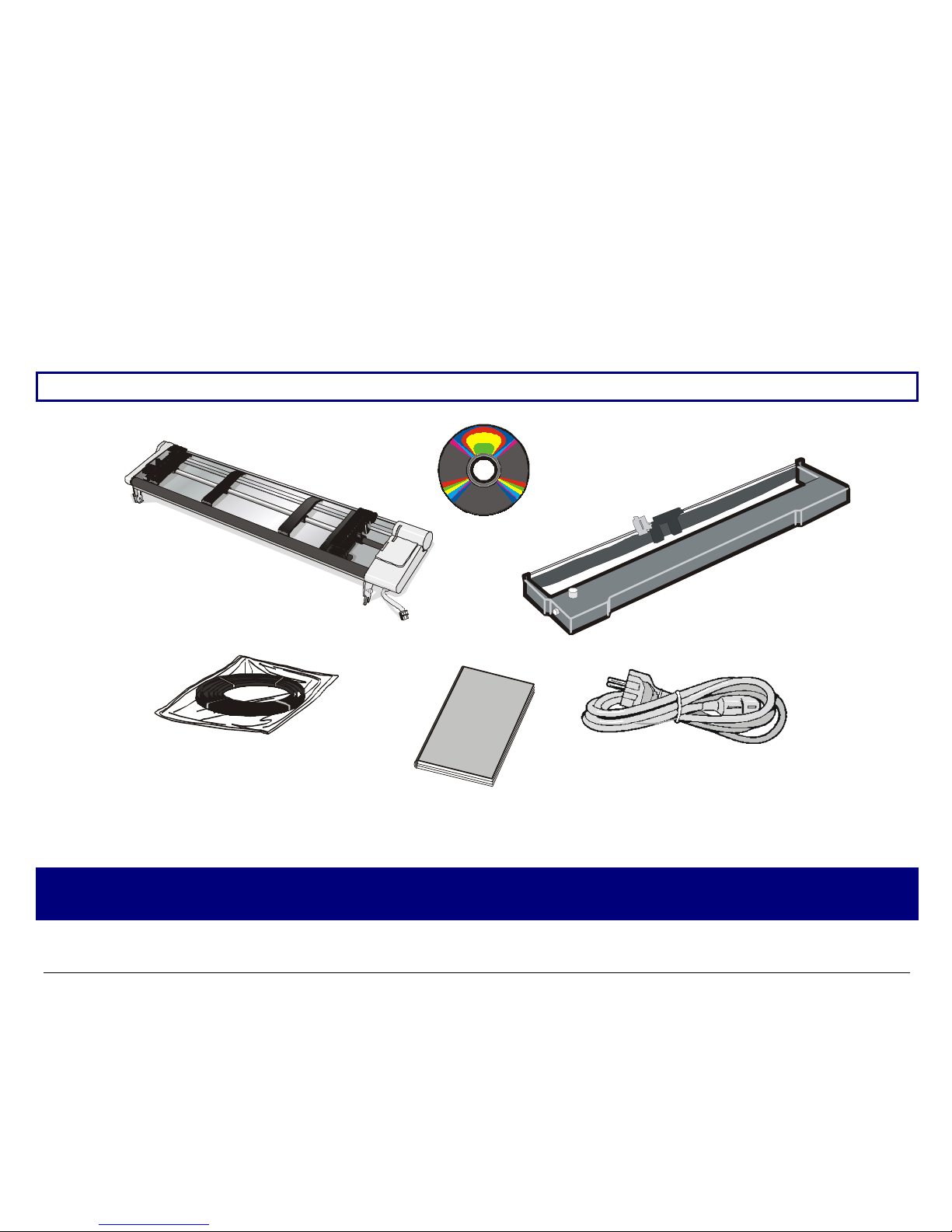
UUnnppaacckkiinngg YYoouurr PPrriinntteer
The following items are included in the box:
Notify any damage to your supplier.
CD-Rom
with User Manual included
Front2 Tractor
optional for the PRTN101 model
Repacking Strips
Power Cable
In stallatio n G u ide
Ribbon Cartridge
Never remove any printer cover unless it is necessary for the installation of a printer accessory
and expressly described in this manual.
2
Page 7
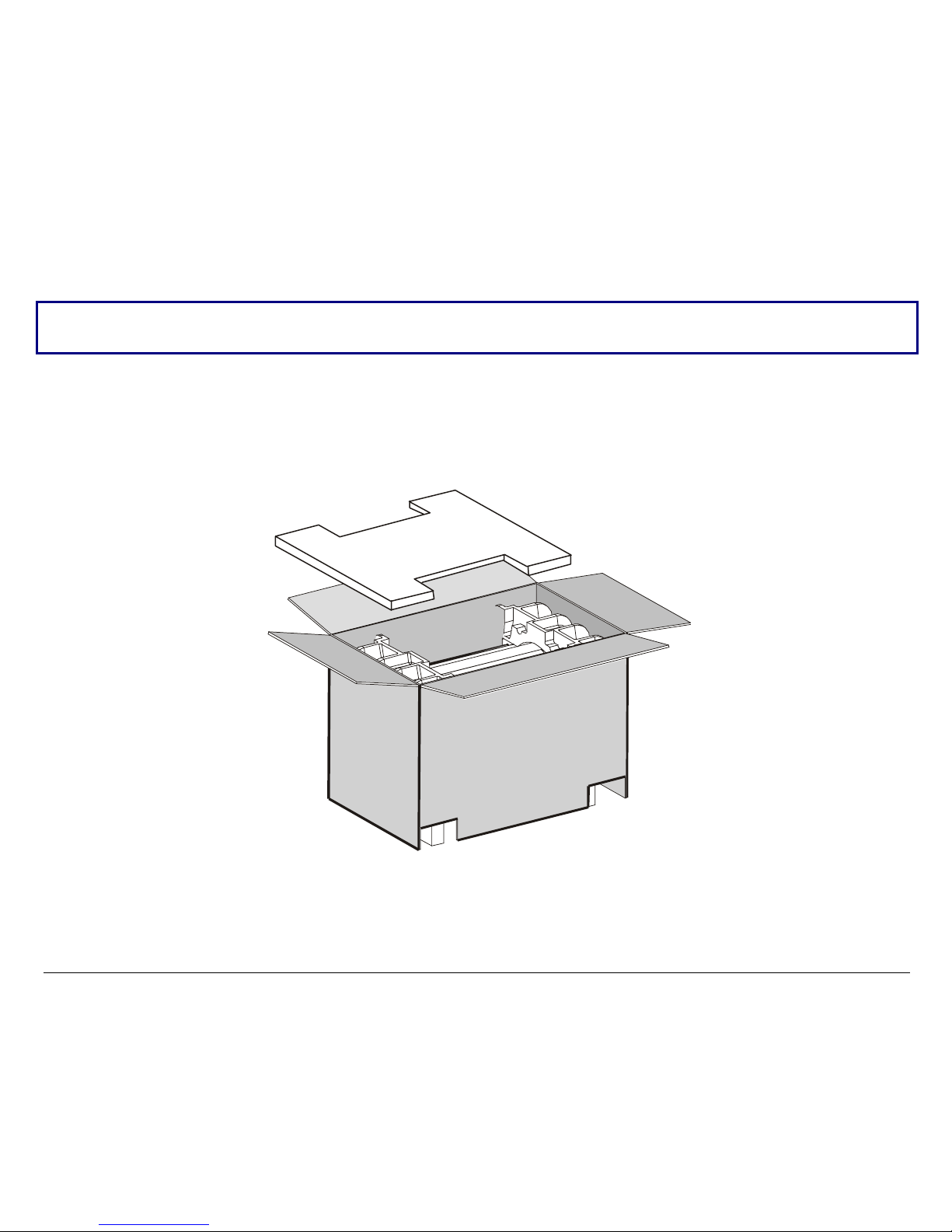
To unpack the printer proceed as follows:
Keep the packing material in a safe place. It must be used if you need to repack the printer for
shipment.
1. Bring the printer box near the final printer location.
2. Cut the packing ribbons and remove the pl astic angles.
3. Remove the polystyrene panel out of the packing box.
3
Page 8
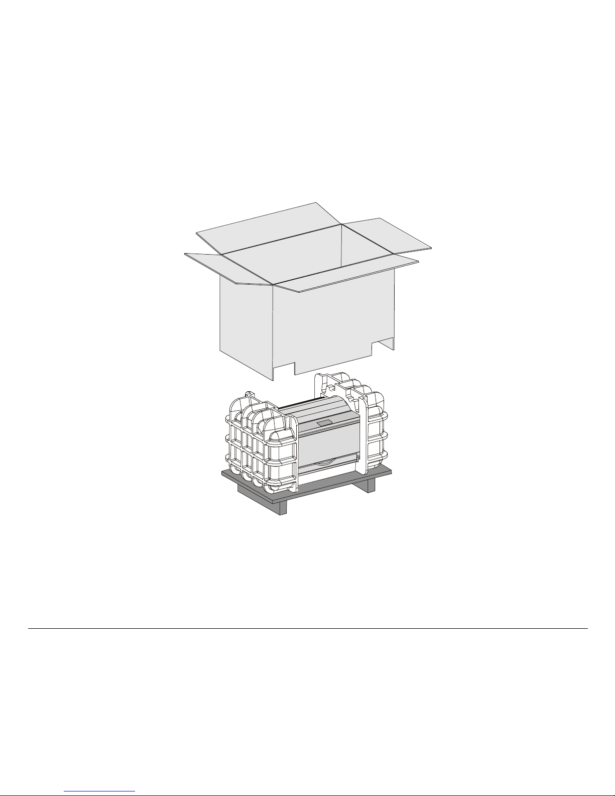
4. Remove the accessories out of the packing box and slide the packing box off the printer.
4
Page 9
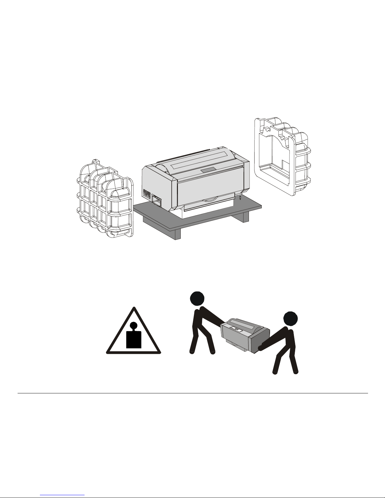
5. Remove the two foam shells on either side of the printer and the plastic bag covering the printer.
6. With the help of another person, move the printer to its final position:
- onto the printer cabinet (for the PRTN102 printer model);
- onto a stable surface, i.e a table (for the PRTN101 printer model without the printer
cabinet option).
33 Kg / 73 Lbs
5
Page 10
s
RReemmoovvaall ooff tthhee SShhiippmmeenntt LLoocckks
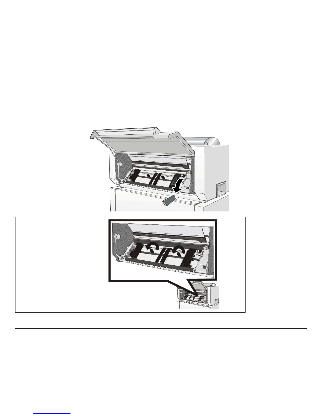
1. Open the tractor area cover and make sure that you remove the shipment lock from the
printer.
2. Unscrew the two fixing
screws.
6
Page 11
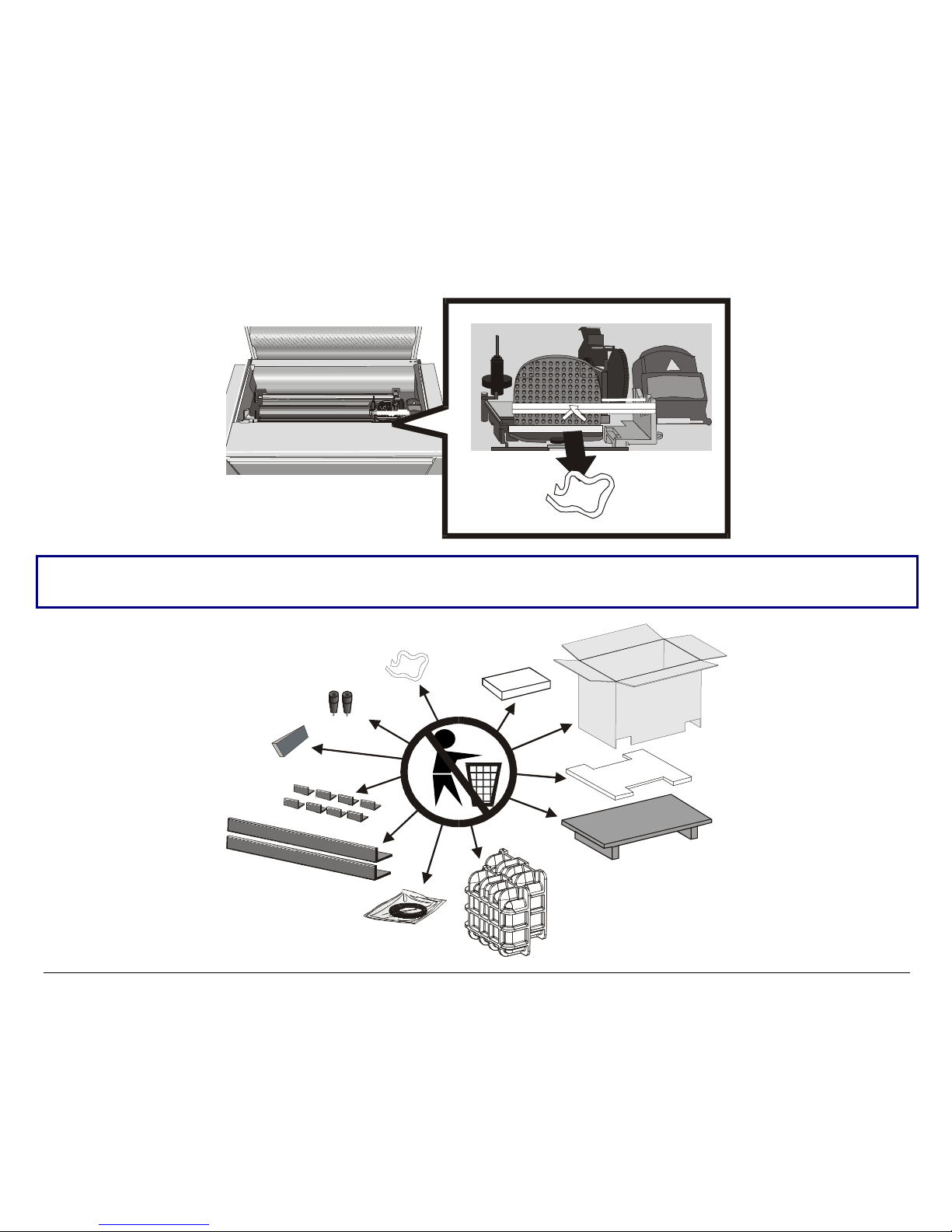
3. Open the upper printer cover and remove the fixing strip from the print head.
Keep all the packing material, together with the repacking kit, in a safe place. Repack the printer in
it original packaging if you need to ship or transport it.
7
Page 12
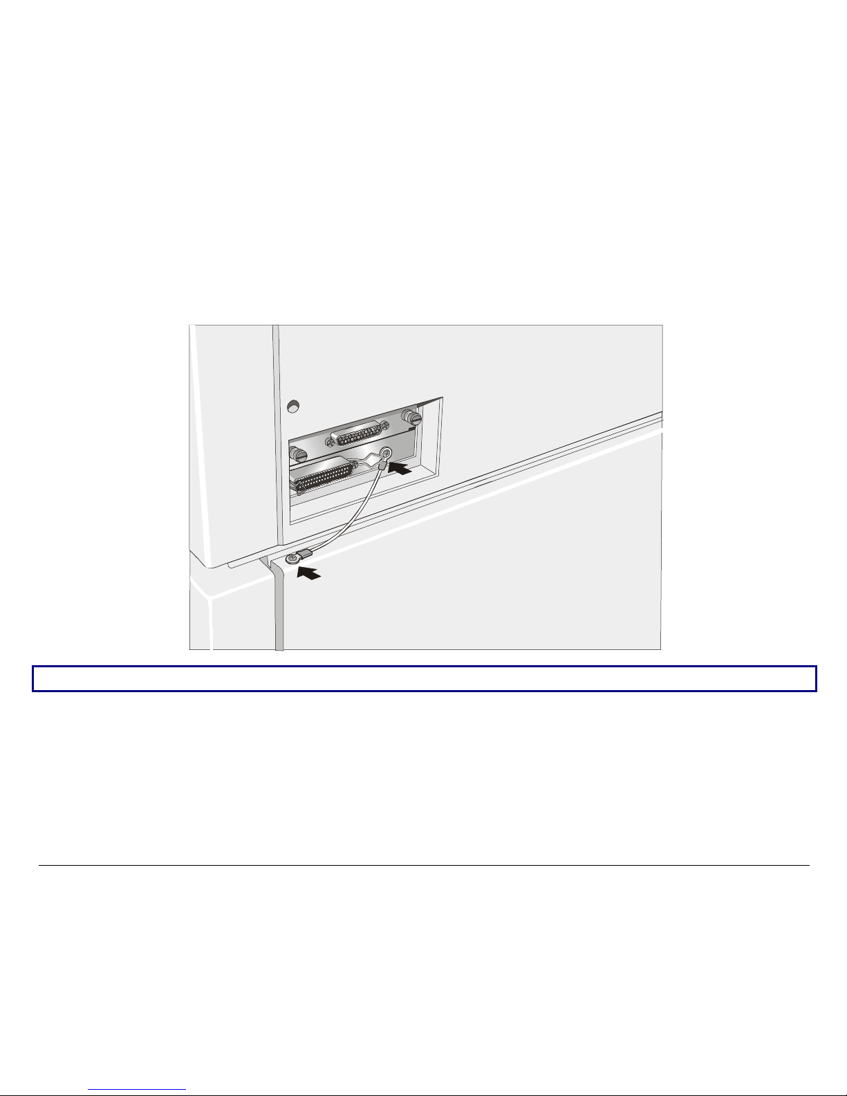
CCoonnnneeccttiinngg tthhee GGrroouunndd CCaabbllee
For the PRTN102 printer model, or the PRTN101 printer model with the cabinet option connect
the ground cable in the interface area on the rear side of the printer cabinet.
If the printer is installed on a table, it is not necessary to connect the ground cable.
8
Page 13
PPrriinntteerr PPaarrttss
g
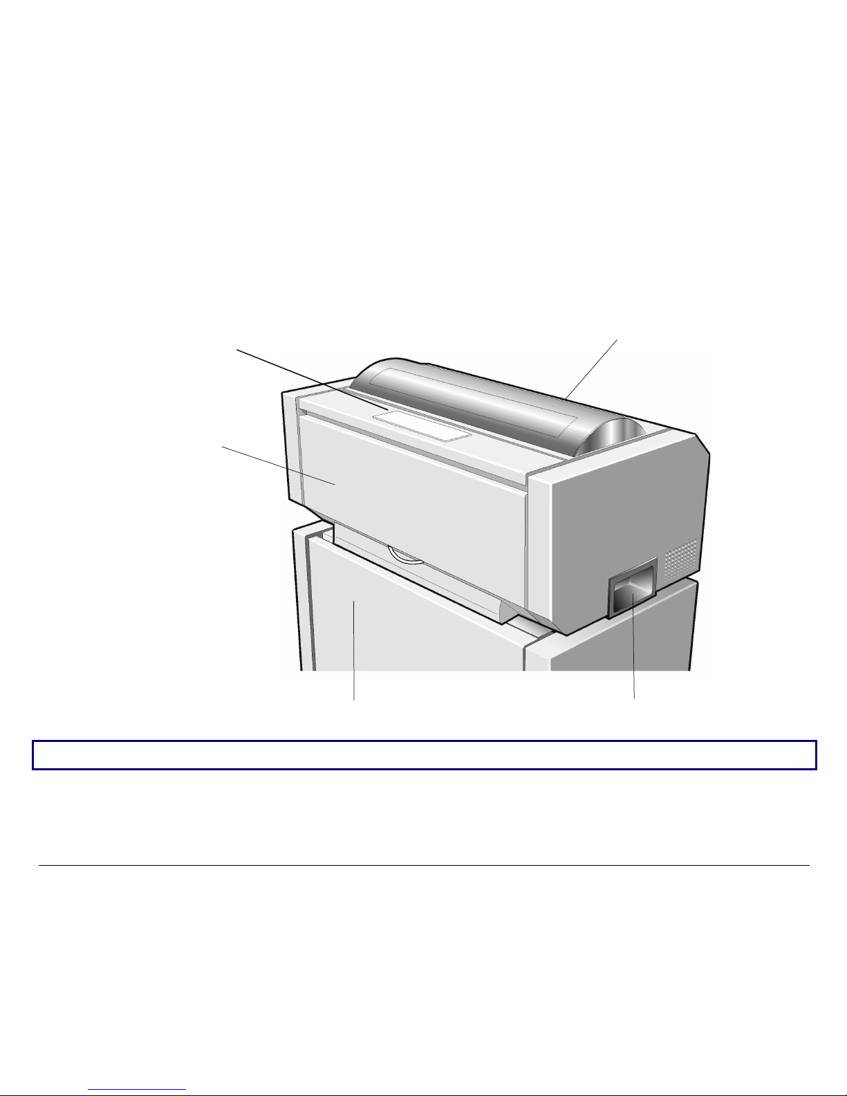
FFrroonntt VViieeww
Tractor Area Cover
Upper Printer Cover
Operator Panel
Printer Cabinet
For the PRTN101 printer model, the printer cabinet is available as an option.
Printer Hand
9
rip
Page 14
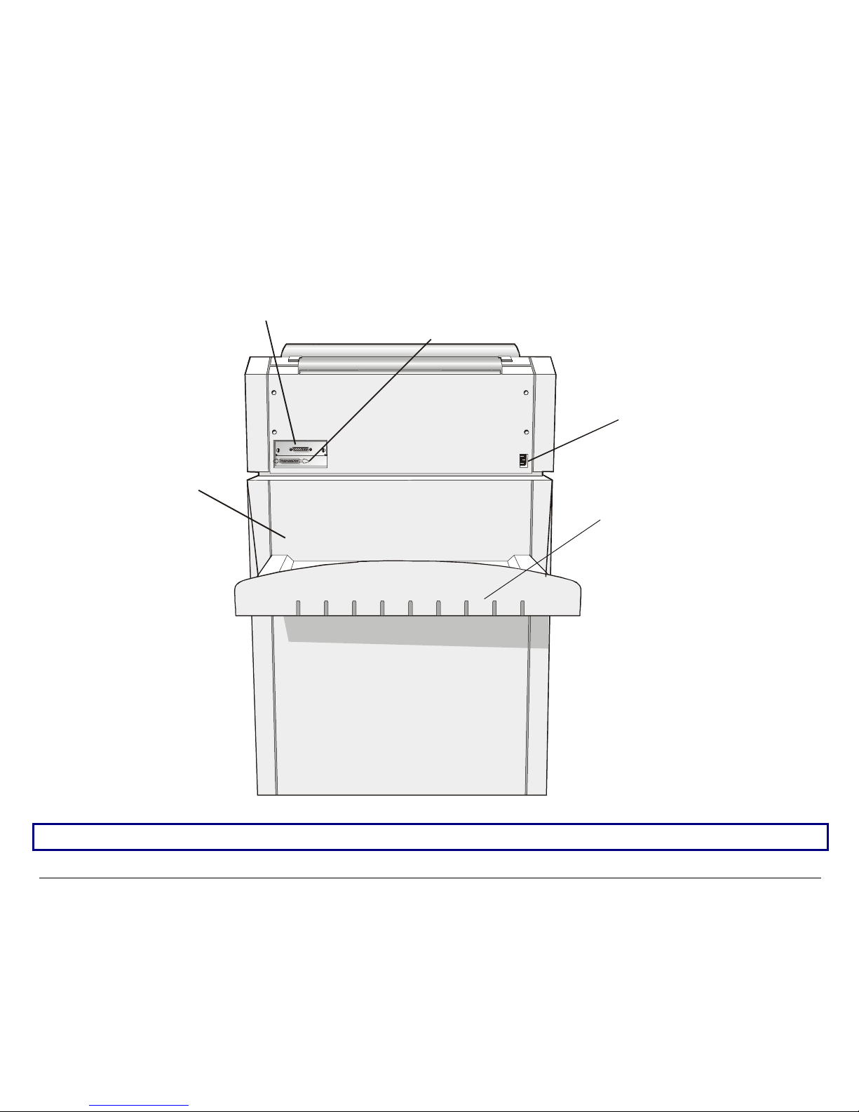
RReeaarr VViieeww
Printer Cabinet
Serial Interface Connector
Pa rallel In terface C onn ector
Power Connector
Paper Output Stacker
For the PRTN101 printer model, the printer cabinet is available as an option.
10
Page 15
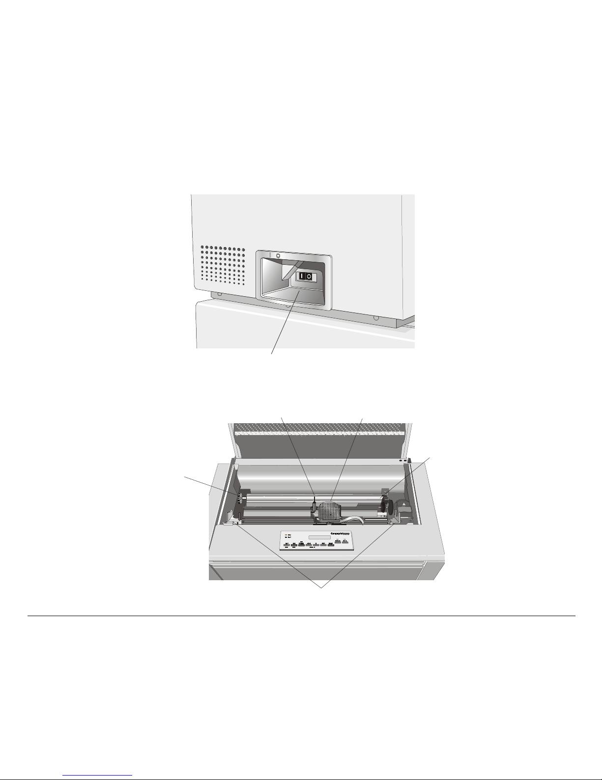
LLeefftt SSiiddee VViieeww
j
g
IInnssiiddee VViieeww
Print Head Gap
Ad
ustment
Power Switch
Color Shifter
Ribbon Cartrid
11
Print Head
e Supports
Paper Bail
Page 16

SSeettttiinngg UUpp YYoouurr PPrriinntteerr
CChhoooossiinngg aa SSuuiittaabbllee LLooccaattiioonn
Consider the following points when you choose the location for your printer:
• The distance between the printer and the host computer must not exceed the length of the
interface cable;
• The location must be sturdy, horizontal and stable;
• Your printer must not be exposed to direct sunlight, extreme heat, cold, dust or humidity (see
"Printer Specifications" later);
• You need a power outlet compatible with the plug of the printer's power cord;
Additionally, you must make sure that when you install the printer in the selected location,
there are sufficient clearances on all sides for easy operation. The required space is shown in the
figure:
80 cm
31.5 in.
80 cm
31.5 in.
0
0
1
9
3
m
c
0
n
0
i
1
4
.
9
3
m
c
n
i
4
.
m
c
0
n
0
i
1
4
.
9
3
m
c
0
n
0
i
1
4
.
9
3
12
Page 17
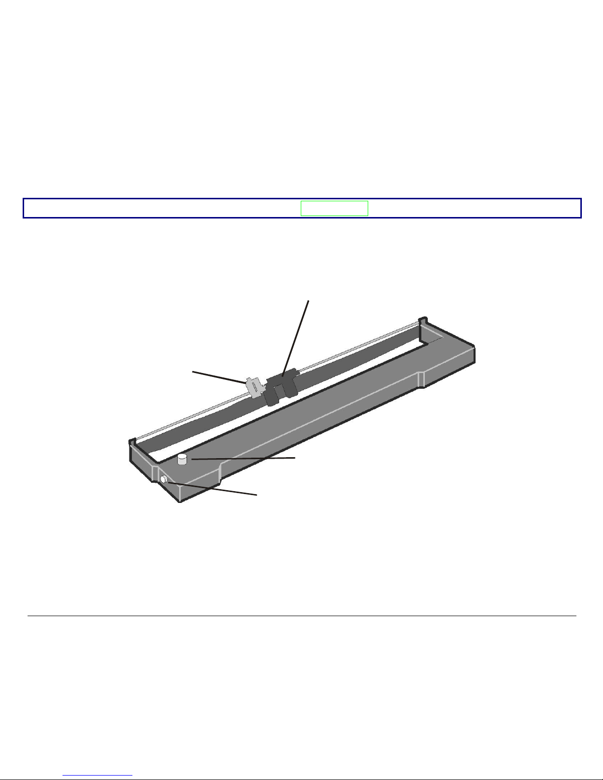
RRiibbbboonn CCaarrttrriiddggee IInnssttaallllaattiioonn
g
Make sure that you are using only Compuprint original consumables.
1. Make sure that the printer is turned off.
2. Find the ribbon cartridge among the accessories.
Co lor S hifter H old er
Ribbon Guide
Tension Knob
Cartrid
13
e Pin
Page 18
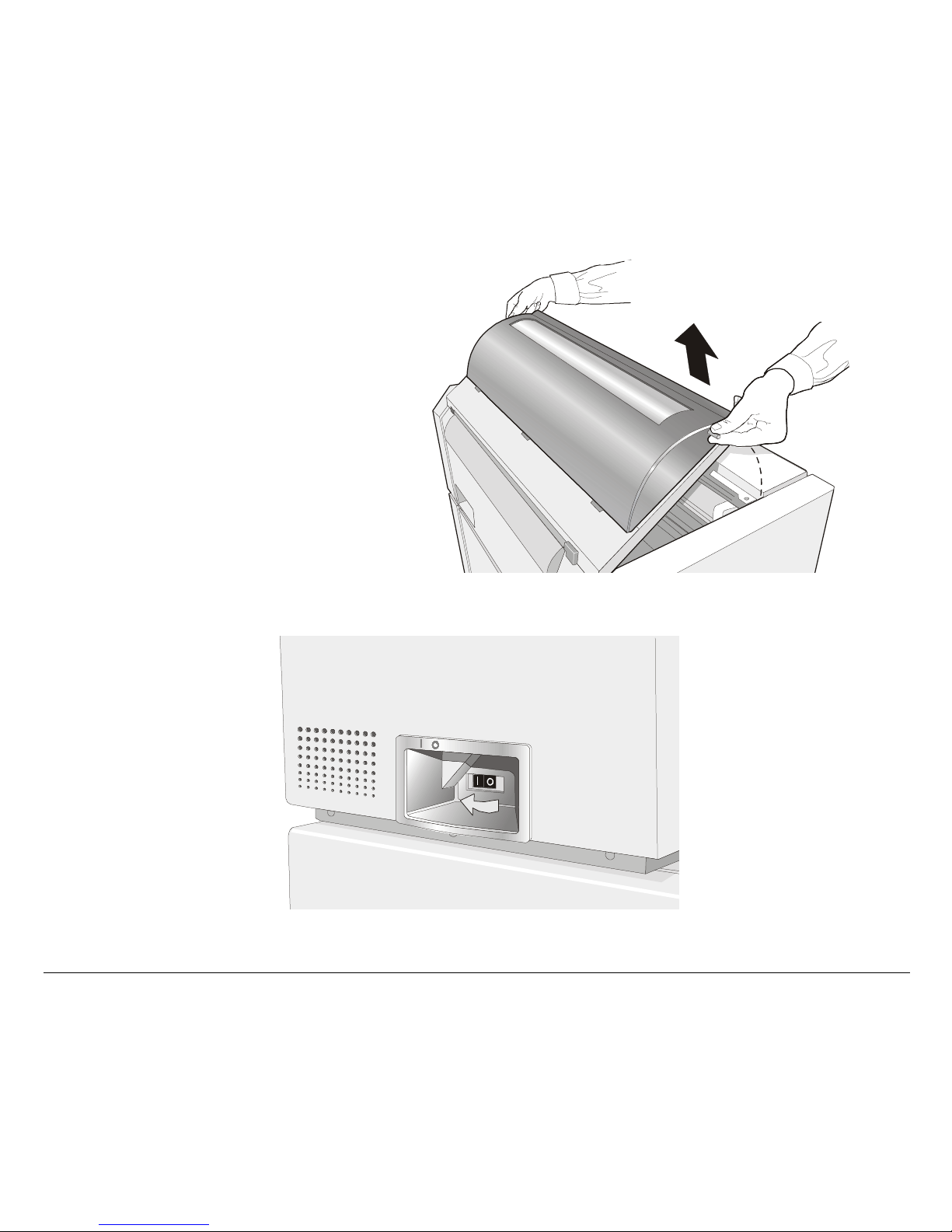
3. Open the top cover using the
handles on the front side of the
covers.
4. Turn the printer on. The print carriage prepares for ribbon cartridge installation.
14
Page 19
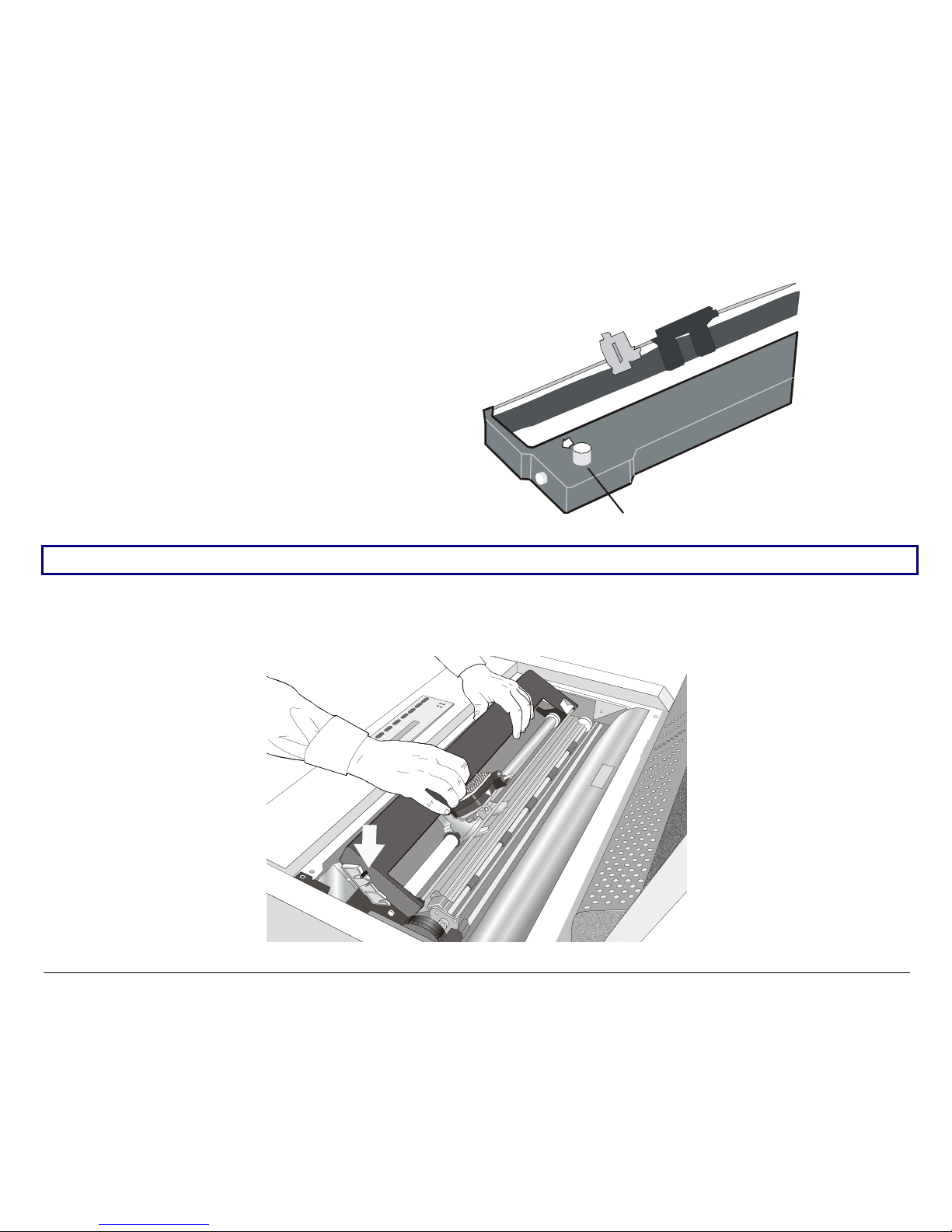
5. Before installing the ribbon
cartridge turn the ribbonwinding knob in the arrow
direction (located on the
cartridge) to take up slack in the
ribbon.
Ribbon Winding Knob
To avoid damage to the ribbon, do not turn the winding knob in the wrong direction.
6. Align the cartridge pins with the locking grooves on the left and right cartridge supports.
15
Page 20
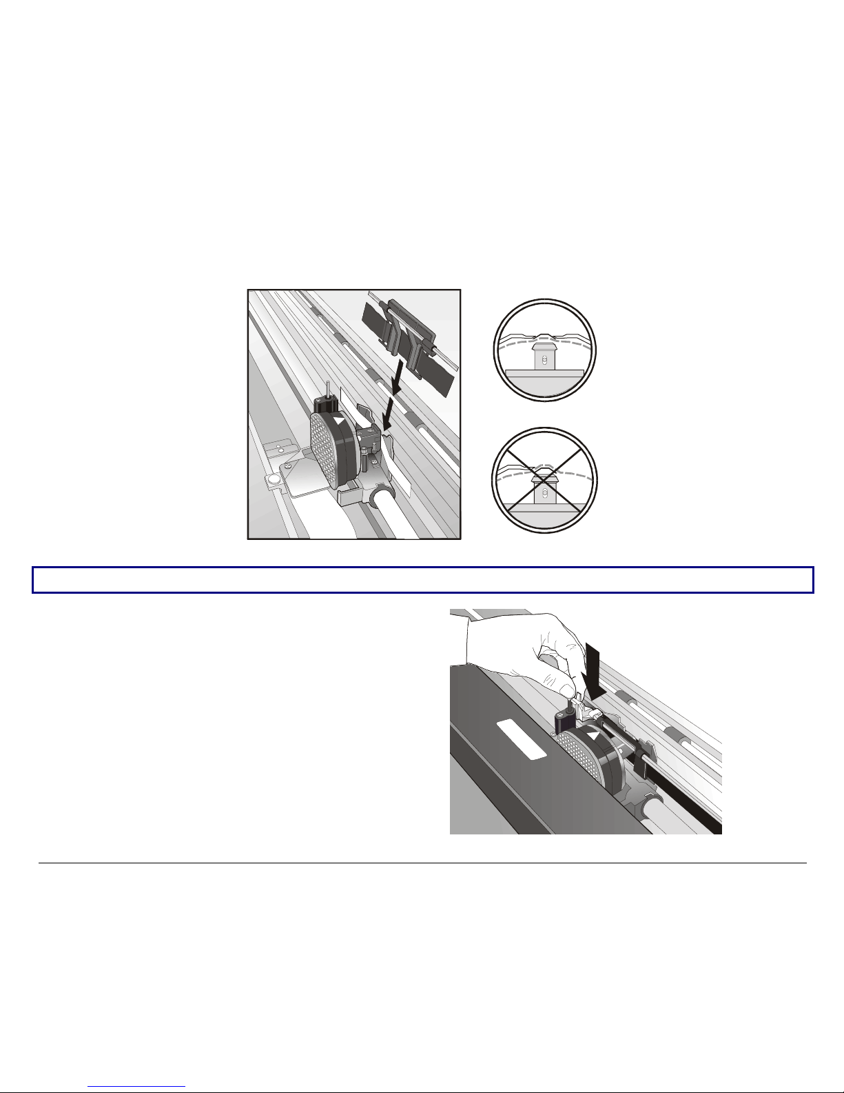
7. Slide and insert the ribbon guide between the print head and the ribbon guide mask holding it
perpendicular to the print head.
Make sure that the ribbon is inserted correctly between the print head and the print head mask.
8. Insert the shifter holder onto the color
shifter as shown in the following
figure.
16
Page 21
9. Turn again the ribb o n-w inding knob in the arrow direction (located on the cartridge) to take
up slack in the ribbon.
10. Push the cartridge down gently unt il it clips into place at both locking p oints .
11. Turn the ribbon-winding knob again in the direction of the arrow to take up slack in the r ibbon.
12. To ensure that the ribbon guide runs freely along the ribbon, manually move the print carriage
horizontally.
If you need to replace the used ribbon cartridge, see "Repl acing The Ribb on Cartridg e", later in this
manual.
17
Page 22
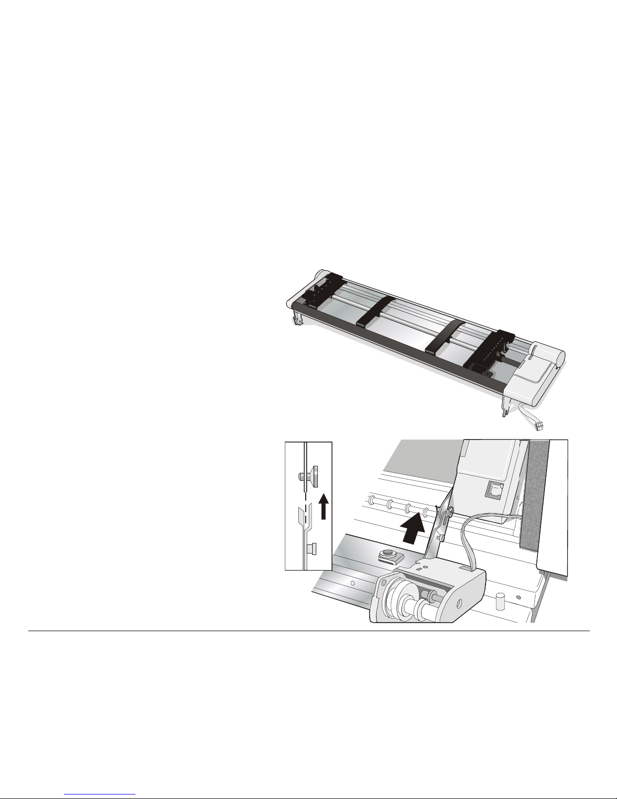
FFrroonntt22 PPuusshh TTrraaccttoorr IInnssttaallllaattiioonn
An additional push tractor may be installed on the printer. This Front2 push tractor unit is delivered
together with the PRTN102 printer model or is available as an option for the PRTN101 printer
model. The Front2 push tractor must be installed on the Front1 push tractor.
1. Find the Front2 push tractor
among the accessories.
2. Align the hooks on both sides of
the Front 2 tractor with the pins
on the Front 1 push tractor.
18
Page 23
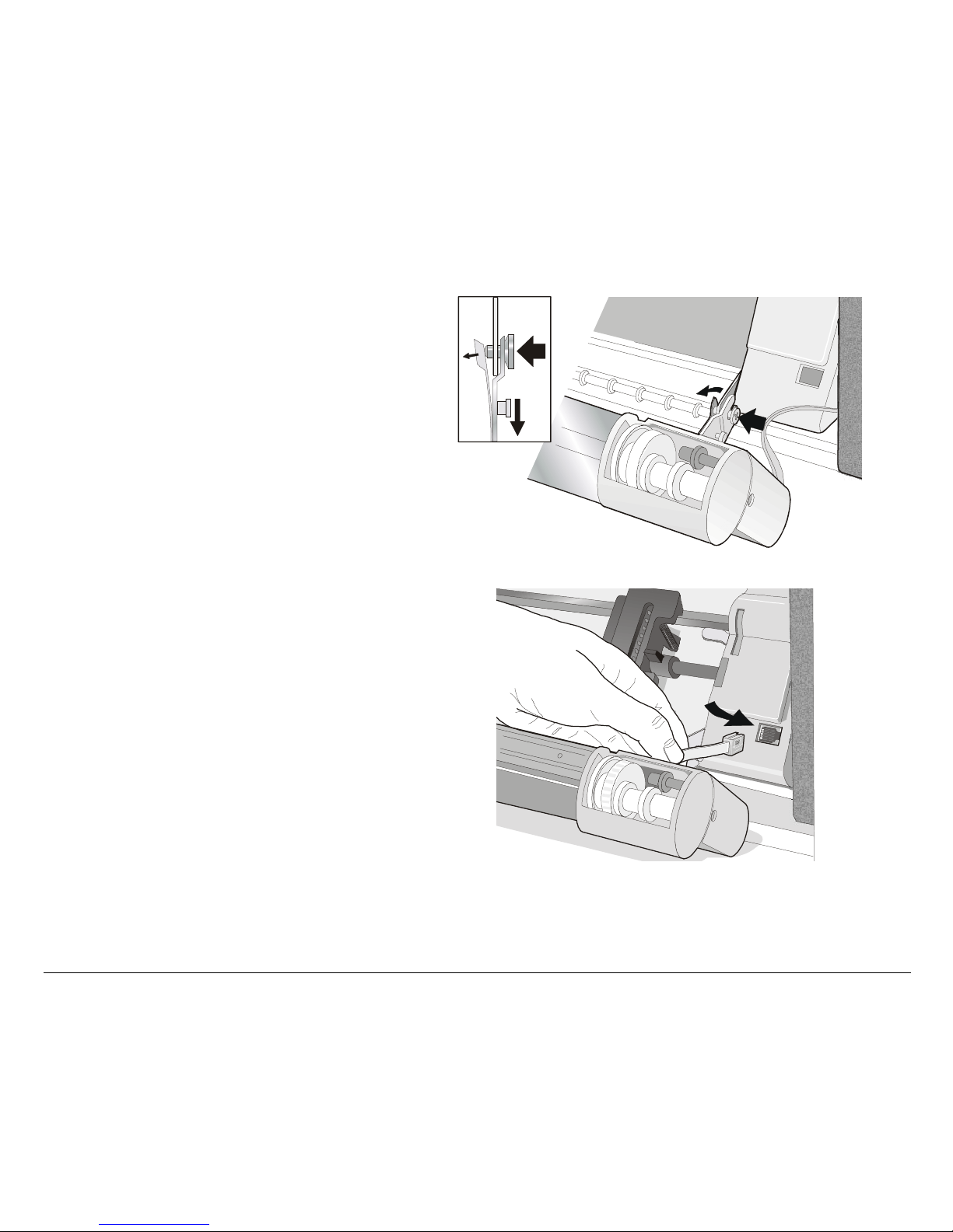
3. Push the Front 2 tractor until it is
fully engaged.
4. Insert the connector cable in the
electrical connector located in the
lower push tractor.
19
Page 24
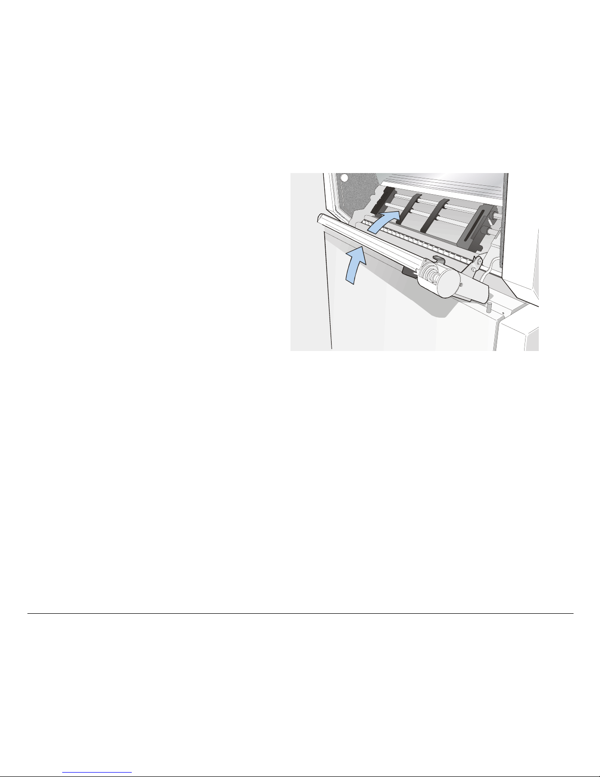
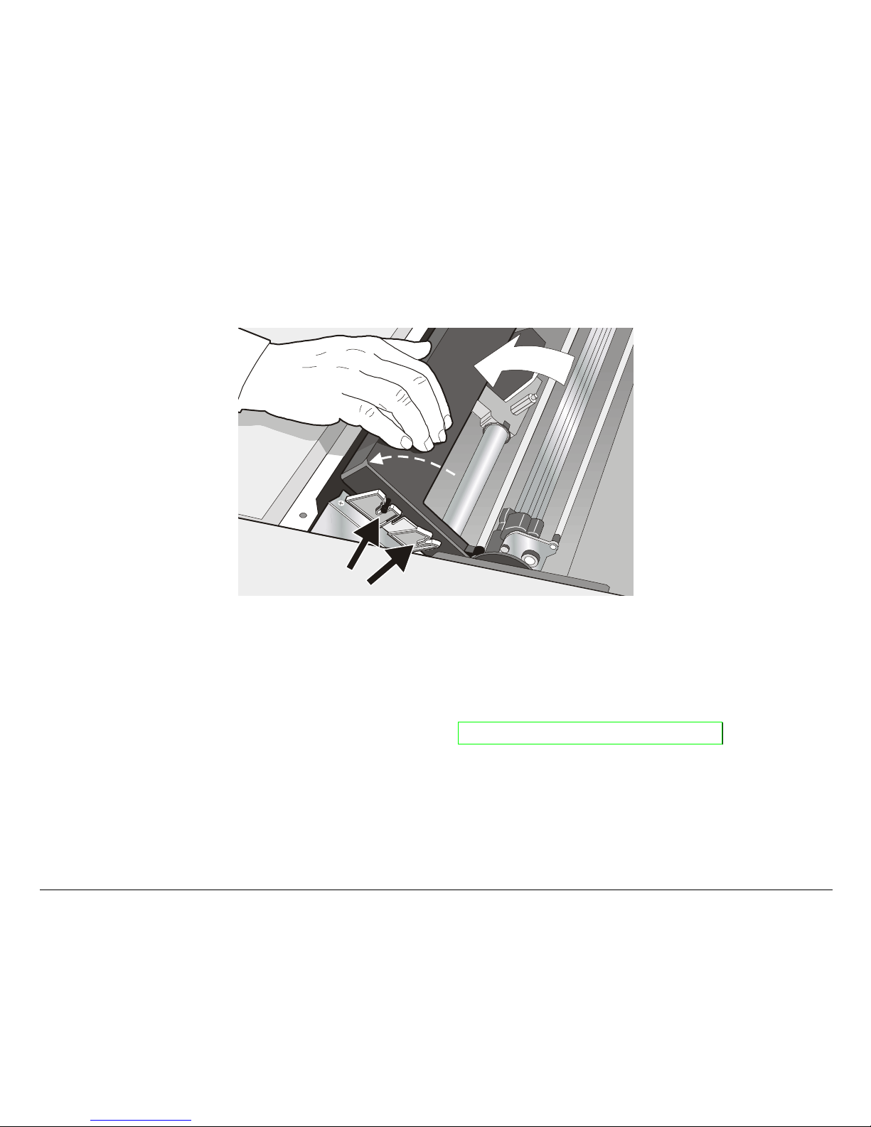
5. Rotate the Front2 push tractor onto
the Front 1 push tractor.
20
Page 25
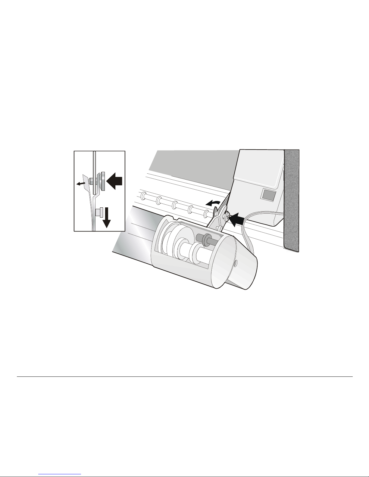
RReemmoovviinngg tthhee FFrroonntt22 PPuusshh TTrraaccttoorr
If you need to remove the upper push tractor, turn the printer off. Disconnect the connector cable and
press on the push buttons to disengage the Front 2 push tractor.
21
Page 26
n
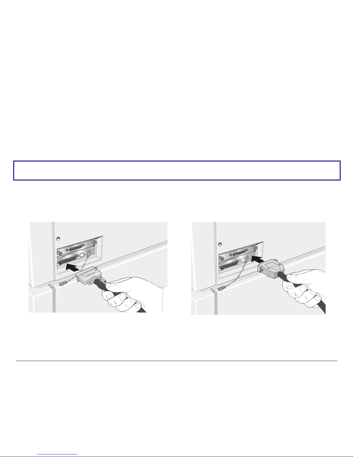
HHoosstt CCoommppuutteerr CCoonnnneeccttiioon
This printer can be connected to your host computer via two available interfaces. The interface
connectors are located on the rear of the printer.
• A bidirectional IEEE1284 parallel interface
• A RS-232C/422A serial interface
Before connecting the interface cable, make sure that the printer and the host computer are
Insert the parallel interface cable into the parallel connec tor and fasten it by mean s of the c lips.
Insert the serial interface cable into the serial connector and fasten it by means of the two screws (use
the screwdriver).
turned OFF .
Parallel Interface
22
Serial Interface
Page 27

SSooffttwwaarree DDrriivveerr SSeelleeccttiioonn
At this point it is necessary to configure your printer for your application package. The installation
procedures depend upon the host environment.
Follow the instructions in the readme file you find on the CD-ROM .
In a WINDOWS 95/98/2000/XP/NT4.0/Millennium® environment the printer supports the Plug &
Play feature.
The printer drivers of all Compuprint printers can be found at the Internet Address
http://www.compuprint.net
23
Page 28
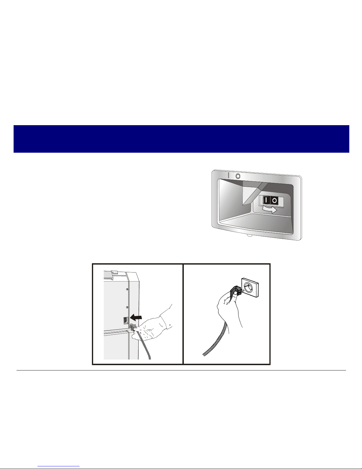
PPoowweerr CCoonnnneeccttiioonn
Make sure that the power outlet matches the printers plug.
1. Make sure the power outlet is near the printer location and easily accessible.
2. Make sure that the power switch is in 0
position (OFF).
3. Insert the power cable plug into the printer connector a nd the other power cable end into a
convenient outlet (the figure shows the European version).
Always use a grounded outlet.
24
Page 29
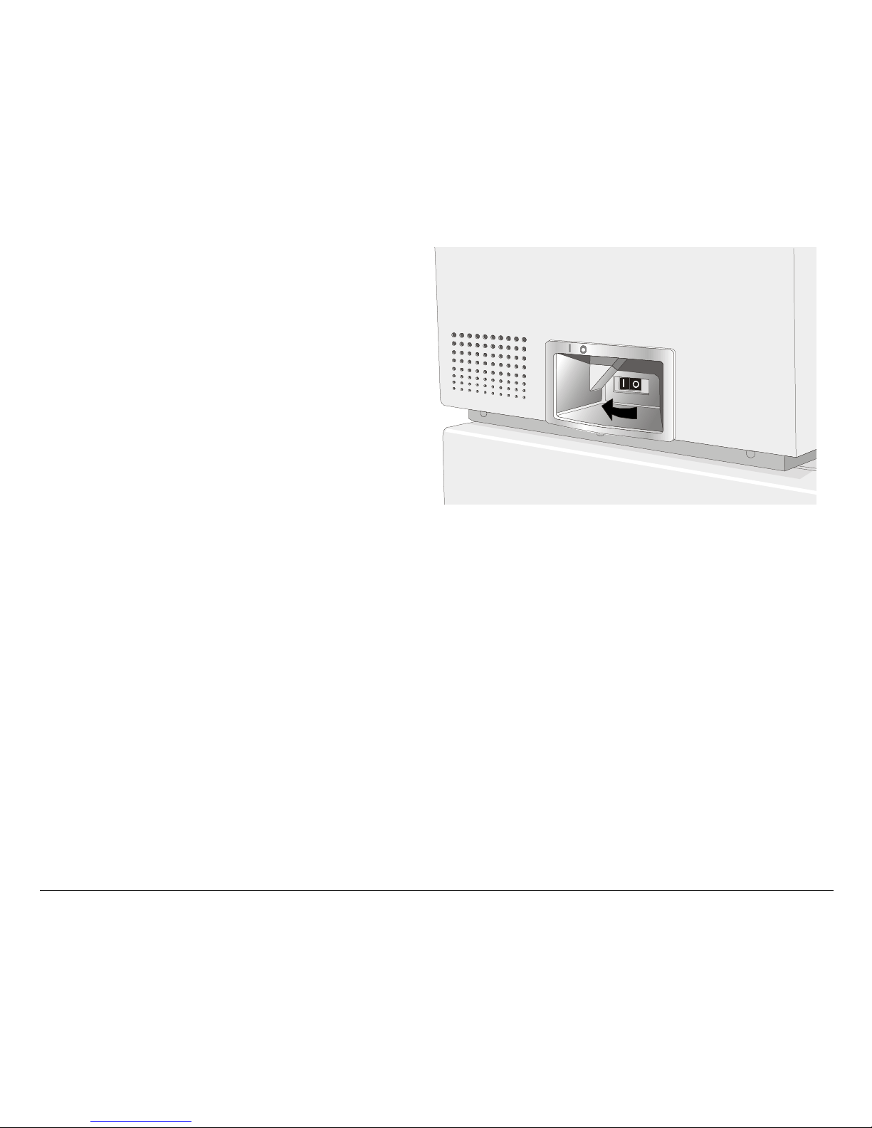
4. If you need to turn the printer on, press the
power switch in the I position (ON).
25
Page 30

SSeelleeccttiinngg tthhee DDiissppllaayy LLaanngguuaaggee
The display messages for this pri nter can be di splaye d in five different languages: Engli sh (Default),
French, German, Italian and Spanish. To select the language, that you prefer, p roceed as follows:
1. Press the
message will be displayed:
2. When you release the
then,
3. Press the ↓ key to enter the setup. The first setup item is displayed:
4. Press the ↓ key until the language first level function is disp layed:
5. Press the → key to pass to the second level functions:
6. Press the ↓ key until the setup language is displayed:
7. Press the → key to scroll the setup l anguages. When the desi red language i s displayed, press the
PROGRAM
in the selected language.
PROGRAM
key to select it. The printer exits the setup. From now on the displ ay messa ges appear
key and keep i t pressed while powering on the printer until the following
RELEASE KEY
key, the following messages will be displayed :
PROGRAM
10200
PRINT OUT? NO
EMUL OPTIONS
FUNCTIONS
BUZZER YES
MENU ENGLISH
26
Page 31

CCoonnffiigguurriinngg tthhee PPrriinntteerr
OOppeerraattoorr PPaanneell PPrreesseennttaattiioonn
The operator panel enables you to perform many of the printer functions including paper path
selections, font selection and the printer setup.
3$7+
3$5.
)URQW
)URQW
7($5
3,7&+
352*5$0 21 /,1(
$/7(51$7( /2$')) /) )217 0$&52
0,&52 )(('
The operator panel consists of:
• A 16 character display (Liquid Crystal Display)
• Five led indicators
• Nine function keys
27
Page 32

DDiissppllaayy MMeessssaaggeess
The printer display is used to indicate the printer status or to request an user intervention.
When the printer is in Ready state, the display gives the following information:
• when paper is already loaded and the
printer is off line (
ON LINE
indicator unlit):
OFF LINE M1
Printer Status
where:
OFF LINE
ON LINE
M1, M2, M3, M4
Current Macro
Indicates the printer status.
Indicate which of the four User Macros is currentl y used.
• when paper is already loaded and the
printer is on line (
ON LINE
indicator lit):
ON LINE M1
Printer Status
Current Macro
28
Page 33

• when there is no paper loaded and the
printer is off line (
ON LINE
indicator unlit):
• when there is no paper loaded and the
printer is on line (
ON LINE
indicator lit):
Load Front1
Current Paper Path
where:
LOAD FRONT 1
LOAD FRONT 2
OFF LINE
ON LINE
M1, M2, M3, M4
ON LINE M1
Printer Status
Indicates that the currently selected paper path is out of paper.
The messages are displayed only for the available paper paths,
according to the installed devices.
Indicates the printer status.
Indicate which of the four User Macros is currentl y used.
Current Macro
29
Page 34

The following messages appear to i ndicate other printer conditions or user intervention requests.
The list is in alphabetical order.
Message Description
ALTERNATE
BUSY M1
COVER OPEN
CLOSE COVER
EJECTING
INITIALIZING LAN
LOAD FRONT1
LOAD FRONT2
LOCKED MENU
MACRO CHANGING
MICRO FEED DOWN
This message appears to indicate that the Alternate functions of the operator
panel keys have been selected pressing the
This message appears to indicate that the printer is printing. It is busy.
When the printer cover is not closed correctly, the buzzer sounds and the
display shows alternately these two messages. Close the printer cover.
The printer is ejecting the paper out of the printer.
This message is displayed when the LAN is reset (only if the LAN interface
board is installed).
These messages are displayed when the corresponding paper path is out of paper.
When the access to the Printer Setups has been locked at the power on, the
printer displays this message.
The macro has been changed and the printer is updating the settings.
The paper is fed in microsteps downwards when pressing the ↓ arrow key .
ALTERNATE
key.
MICRO FEED UP
OPT. I/F CHANGED
PRESS ON LINE
The paper is fed in microsteps forwards when pressing the ↑ arrow key.
These messages are displayed at power on when the I/F board option has been
changed previously in the printer. Press the
30
ON LINE
key to confirm.
Page 35

Message Description
OPER. INTERRUPTED
PARKING
PATH CHANGING
PRESS A KEY
NVM CHANGED
RELEASE KEY
REMOTE CONTROL
RESET & BREAK
SELF TEST
TEAR IF NECESS.
EJECT PAPER
TEAR IF NECESS.
PARK PAPER
This message is displayed if the
park procedure.
The printer is parking the fanfold paper.
The path has been changed and the printer is updating the settings.
The NVM has been changed. Press any key to set the printer.
This message is displayed when you can release the
test selection or in the Power-on Configuration procedure.
This message is displayed when the printer operates from remote control (only
if the LAN interface board is installed).
The printer received a reset and break command via interface.
Printing the self-test page.
These messages are displayed when the printer receives a paper parking
command and the
the fanfold then press the
These messages are displayed when the printer receives a paper parking
command. Tear off the fanfold paper if necessary and then press the
to park the paper.
TEAR NO
ALTERNATE
item is selected for the tear-off function. Tear off
PARK
key to eject the paper.
key has been pressed to interrupt a
PROGRAM
key in the Self-
PARK
key
31
Page 36

Message Description
TEAR OFF PAPER
EJECT PAPER
TEAR OFF PAPER
PARK PAPER
UNLOCKED MENU
For the error messages see "Error Handling" later in this manual.
These messages are displayed when the printer receives a paper ejecting
command (
TEAR NO
item has been selected for the tear-off function) but was
not able to execute it, because the paper to be ejected is longer than 18 inch.
Tear off the fanfold paper and then press the
PARK
key to eject the paper.
These messages are displayed when the printer has received a paper parking
command but was not able to execute it, because the paper to be parked is
longer than 18 inch. Tear off the fanfold paper and then press the
PARK
key to
park the paper.
When the access to the Printer Setups has been unlocked at the power on, the
printer displays this message.
32
Page 37

IInnddiiccaattoorrss
Lit when the printer can receive and print data (printer online).
ON L IN E
PROGRAM
ALT ERNAT E
Blinks when there is data in the buffer and the printer is offline.
Unlit when the printer is disabled and the buffer does not contain any data, or
during the initialization, setup or tests.
Blinks when one of the printer setup procedures has been selected:
Configuration
Lit when the alternate function of the keys has been enabled pressing the
ALTERNATE
or
Power-On Configuration
key.
.
Program
Front 1
Front 2
Lit when the Front1 paper path is selected.
Unlit when the Front1 paper is not selected
Lit when the Front2 paper path is selected.
Unlit when the Front2 paper is not selected.
33
Page 38

FFuunnccttiioonn KKeeyyss
g
Pressing the function keys it is possible to activate the functions indicated by the word or symbol
signed near the key. Each key may have different functions, according to the selected function
modes: Normal, Alternate or Program.
ram Function
Pro
352*5$0 21 /,1(
Normal function
Normal Function
Alternate Function
Program Function
3$7+
3$5.
7($5
3,7&+
$/7(51$7( /2$')) /) )217 0$&52
0,&52 )(('
Alternate function
normal
The
function of the keys is written above the keys and does not require any
previous action to select it.
alternate
The
pressing the
When the alternate function of the keys is selected, the
the display shows
program
The
•
If you press the key while powering the printer on, the
function of the keys is written below the keys and is selected
ALTERNATE
ALTERNATE
function of the keys is selected pressing the
key.
.
ALTERNATE
PROGRAM
indicator is lit and
key, where:
Power-On Configuration
is selected.
•
If you press the key when the printer is enabled without printing or disabled
(
ON LINE
indicator unlit), the
In the Program Setup mode only the four arrow keys and the
enabled and the
PROGRAM
indicator is lit.
Program Setup
is selected.
PROGRAM
key are
34
Page 39

ON LINE Key
ON LINE
Normal
Function
Program
Function
PROGRAM Key
PROGRAM
Normal
Function
Program
Function
Enables or disables the printer.
If this key is pressed while powering the printer on, the self test is printed;
•
the printout is stopped pressing this key again.
In an error condition, once the error cause has been removed, press this
•
key to enable the printer
Pressing this key, the input buffer is cleared an a break (250 msec.) on a serial
interface is sent. The message RESET & BREAK is displayed.
Enables the printer setups as follows:
Pressing this key while powering on the printer, th e
•
Configuration
Pressing this key when the printer is enabled without printing or disabled
•
the
Program Setup
Exits the printer setups.
is selected.
is enabled (
PROGRAM
indicator lit).
Power-On
MACRO Key
MACRO
→
Normal
Function
Program
Function
Selects one of the user macros (Macro 1, Macro 2, Macro 3 or Macro 4). If you
want to select the displayed macro, wait for 2 seconds without pressing any
key and the parameters of this macro will be set .
Scrolls the parameters of the functions or macros forwards.
35
Page 40

FONT Key
FONT
Normal
Function
←
Program
Function
LF Key
LF
MICRO FEED
↑
Normal
Function
Alternate
Function
Program
Function
LOAD/FF Key
LOAD/FF
MICRO FEED
Normal
Function
Alternate
Function
Selects the font to be used with the currently selected pitch. The selected font
is valid until the printer is turned off or a new font is selected using this key.
Scrolls the parameters of the functions or macros backwards.
Performs a line feed according to the current line spacing settings.
Moves the paper forward in microsteps. Keeping the key pressed the paper is
moved continuously at increasing speed.
Scrolls the setup and macro functions backwards.
Executes a Form Feed (FF): when paper is loaded into the printer, it advances
to the following page; if no paper is loaded, it is positioned for printing .
Moves the paper backward in microsteps. Keeping the key pressed the paper
is moved continuously at increasing speed.
↓
Program
Scrolls the setup and macro functions forwards.
Function
36
Page 41

ALTERNATE Key
ALTERNATE
Normal
Function
Alternate
Function
TEAR/PITCH Key
TEAR
PITCH
Normal
Function
Alternate
Function
Enables the alternative key functions.
If the printer is receiving print data, press the
ALTERNATE
key.
ON LINE
If no printing data are in the print buffer, pressing the
key before pressing the
ALTERNATE
key, the printer
goes offline.
The display then shows
of the keys is enabled (
ALTERNATE
ALTERNATE
May be used to abort paper parking procedure. See also “
Paper Parking
”, later in this manual.
to indicate that the Alternate Function
indicator lit).
How to Handle the
When the printer is in Program Setup Mode, this key is disabled.
Disables the alternative key functions.
Moves the paper to the tear-off position (
in the
Program Setup
).
TEAR NORMAL
function must be selected
Selects the pitch to be used with the currently selected font. The selected pitch is
valid until the printer is turned off.
37
Page 42

PATH/PARK Key
PATH
PARK
Normal
Function
Alternate
Function
Selects one of the paper paths (FRONT 1 or FRONT 2) in offline status. The
parameters of the displayed path are set after 2 seconds without pressing any key.
Parks the paper in the currently selected paper path.
Key Combinations
ONLINE + MACRO + ALTERNATE
Normal
Function
Lock or unlock the access to the printer setups. See later
“How to Lock/Unlock the Printer Setups” section.
38
Page 43

PPrriinntteerr SSeettuuppss
The main printer setup parameters can be selected via the operator panel. The setup parameters are
divided into two printer setups, the Power-O n Configuration , that allows a complete configuration at
installation time according to the hardware and the emulation types, and the Program Setup, that
allows you to set the functions that are the most useful in your daily job. These settings can be
selected when the printer is online without printing or offline (
the NVM.
ON LINE
indicator unlit) and stored i n
EEnntteerriinngg tthhee PPrriinntteerr SSeettuuppss
• Press the
message is displayed to select the Power-O n Configuration.
• Press the
indicator unlit) to select the Program Setup.
PROGRAM
PROGRAM
key and keep it pressed at the printer power on unti l the RELEASE KEY
key when the printer is online without printing or offline (
MMoovviinngg wwiitthhiinn tthhee PPrriinntteerr SSeettuuppss
The arrow keys ↑, ↓, ← , → are used to move within the different functions inside the Printer Setups.
See the following description of the setup items.
ON LINE
39
Page 44

LLeeaavviinngg tthhee PPrriinntteerr SSeettuuppss
• Pressing the
PROGRAM
in the Power-On Configuration key the printer exits from the setup and
the new settings will be automatically saved.
• Pressing the
PROGRAM
key in the Program Setup, the following choice is offered for the storage of
the values set:
STORE? QUIT
STORE? SAVE
The new settings are not activated and the old settings remain valid.
The new settings are stored permanently in the NVM (Non Volatile
Memory).
STORE? CURRENT
The new settings remain valid until th e printer is tur ned off .
Press the → or ← keys to scan these selections forwa rd and backwards. When the desired setting is
displayed, press the
PROGRAM
key to exit from the Setup.
40
Page 45

PPoowweerr--OOnn CCoonnffiigguurraattiioonn
The default values of the various functions are indicated in bold.
EEnntteerriinngg tthhee PPoowweerr--OOnn CCoonnffiigguurraattiioonn
1. Make sure that the printer is turned off.
2. P ress and hold the
message is displayed. As soon as the
displayed:
then,
PROGRAM
key pressed while powering on the printer until the RELEASE KEY
PROGRAM
PRINT OUT? NO
10200
key gets released, the following message will be
41
Page 46

Main Structure
This figure shows the structure of the Power-On Configuration and how to move inside the Setup.
Print out? NO
Em ul. Options
Parall Interface
Serial Interface
Functions
Back to M FG ? N O
Print out? YES
LAN Interfa ce
42
Page 47

The setup item Functions groups the following printer functions:
• Buzzer setting,
• Paper loading sequence,
• Ribbon type,
• Bar code density,
• Text printing direction,
• Graphics printing direction,
• Bar code printing direction,
• Graphics printing speed,
• Paper path at power on,
• Language of the display messages,
• Paper tractor jam sensors,
• Tear-off position adjustment
Printout of the Printer Settings
PRINT OUT? NO
↓
EMUL. OPTIONS
→
or ←
PRINT OUT? YES
PRINT OUT? NO
PRINT OUT? YES
The Setup is not printed.
The printer setup is printed showing the currently selected values. The
printout starts as soon as you select this value.
43
Page 48

Emulation Options
This setup defines the available options according to the selected emulation and is structured as
follows:
Options
Emul. Options
Parall. Interface
Emul EPSON LQ
Char. Set ...
Nation ...
Auto C R ...
Auto LF …
Em u l IBM...
Char. Set ...
Nation ...
Auto CR …
Auto LF ...
20 C PI IBM ...
44
Page 49

Setting the Emulation Options
Printer Emulation
PRINT OUT? NO EMUL. OPTIONS
↑
EMUL. OPTIONS
↓
PARALL INTERFACE
EMUL. IBM 2391
CHAR. SET CS2
→
↑
EMUL. EPSON LQ
EMUL. IBM XL24
EMUL. IBM XL24AGM
↓
EMUL EPSON
EMUL IBM XL24
EMUL IBM XL24AGM
EMUL. IBM 2391
The printer uses the EPSON Series emulation.
The printer uses the IBM Proprinter XL24 emulation.
The printer uses the IBM Proprinter XL24 AGM emulation.
The printer uses the IBM Personal 2391+ emulation.
→
→
→
→
or ←
←
or
←
or
or ←
45
Page 50

EPSON Character Sets
EMUL. EPSON LQ
↑
CHAR. SET CS1
CHAR. SET CS2
CHAR. SET ITALIC
↓
NATION CP437
→ or ←
→ or ←
→ or ←
These items select the character set to be used in EPSON emulation.
IBM Character sets
EMUL. IBM xxx
↑
CHAR. SET CS1
CHAR. SET CS2
↓
NATION CP437
→ or ←
→ or ←
These items select the character set to be used in IBM Proprinter emulation.
46
Page 51

EPSON National Character sets
CHAR. SET CS2
↑
NATION CP437
NATION …
NATION LATIN A1
↓
AUTO CR YES
→ or ←
→ or ←
→ or ←
The following national character sets ar e available:
CP 437
CP 857 CP 858 CP 860 CP 862 CP 863 CP 864 CP 865 CP 866
CP 867 CP 876 CP 877 CP 1250 CP 1251 CP 1252 CP 1253 CP 1254
CP 1255 CP 1256 CP 1257 GOST TASS MAZOWIA ISO 8859/1 ISO 8859/2
ISO 8859/3 ISO 8859/4 ISO 8859/5 ISO 8859/6 ISO 8859/7 ISO 8859/8 ISO 8859/9 ISO 8859/15
CP 437SL CP 1098 UKRAIN KOI8-U USA FRANCE GERMANY ENGLAND
CP437 G 96GREEK CP850 CP851 CP 852 CP 853 CP 855
DENMARK1 SWEDEN ITALY SPAIN1 JAPAN NORW AY DENMARK2 SPAIN2
LATIN A1
The CP 858 and ISO 8859/15 character sets contain the Euro character.
47
Page 52

IBM National Character Sets
CHAR. SET CS2
↑
NATION CP437
NATION …
NATION KOI8-U
↓
AUTO CR NO
→ or ←
→ or ←
→ or ←
The following national character sets can be se lected:
CP 437
CP 857 CP 858 CP 860 CP 862 CP 863 CP 864 CP 865 CP 866
CP 867 CP 876 CP 877 CP 1250 CP 1251 CP 1252 CP 1253 CP 1254
CP 1255 CP 1256 CP 1257 GOST TASS MAZOWIA ISO 8859/1 ISO 8859/2
ISO 8859/3 ISO 8859/4 ISO 8859/5 ISO 8859/6 ISO 8859/7 ISO 8859/8 ISO 8859/9 ISO 8859/15
CP 437SL CP 1098 UKRAIN KOI8-U
CP437 G 96GREEK CP850 CP851 CP 852 CP 853 CP 855
TThhee CCPP 885588 aanndd IISSOO 88885599//1155 cchhaarraacctteerr sseettss ccoonnttaaiinn tthhee EEuurroo cchhaarraacctteerr..
48
Page 53

CR Code Behavior
NATION xxx
↑
AUTO CR NO
AUTO CR YES
↓
AUTO LF NO
AUTO CR NO
AUTO CR YES
→ or ←
→ or ←
No automatic carriage return is performed after a LF, VT or ESCJ code.
The printer performs an automatic carriage return after a LF, VT or ESCJ code.
49
Page 54

LF Code Behavior
AUTO CR xx
↑
AUTO LF NO
AUTO LF YES
AUTO LF HOST
↓
20 CPI IBM NO
or
EMUL. OPTIONS
→ or ←
→ or ←
→ or ←
AUTO LF NO
AUTO LF YES
AUTO LF HOST
No Automatic LF after CR.
Automatic LF after CR.
Only in EPSON emulation. The printer checks the AUTOFEEDXT signal coming
from the host and executes an automatic LF after CR, if the signal is low.
50
Page 55

IBM Compressed Printing
These items are displayed only if the IBM emulation is selected.
AUTO LF NO
↑
20 CPI IBM NO
20 CPI IBM YES
↓
EMUL. OPTIONS
20 CPI IBM NO
20 CPI IBM YES
→ or ←
→ or ←
The compressed printing is performed at 17.1 cpi.
The compressed printing is performed at 20 cpi.
51
Page 56

Parallel Interface
This setup defines the use of the parallel interface and is structured according to the interface
specific parameters.
Parallel Interface Parameters
Parall Interface
Serial Interface
RU
LAN Interface
1284 Bidir. I/F
Select-In Host
Data Bits 8
Input Buffer 2K
CX. Parallel I/F
Select-In On
Data Bits 7
Input Buffer …
52
Page 57

Setting the Parallel Interface Parameters
Interface Type
EMUL. OPTIONS PARALL INTERFACE
↑
PARALL INTERFACE
↓
SERIAL INTERFACE
or
LAN INTERFACE
1284 BIDIR. I/F
CX. PARALLEL I/F
→
CX. PARALLEL I/F
SELECT-IN HOST
↑
1284 BIDIR. I/F
↓
Bidirectional IEEE 1284 parallel interface.
Centronics type parallel interface (monodirectional).
→
→
or ←
or ←
Setting the Select-In Signal
1284 BIDIR . I/F
↑
SELECT-IN HOST
SELECT-IN ON
↓
DATA BITS 8
→ or ←
→ or ←
SELECT-IN HOST
SELECT-IN ON
The printer checks the SELECT-IN signal coming from the host.
The SELECT-IN signal of the parallel interface is ignored and treated always
as ON.
53
Page 58

Number of Data Bits
SELECT-IN HOST
↑
DATA BITS 8
DATA BITS 7
↓
INPUT BUFFER 2K
→
→
or ←
or ←
Selection of the number of data bits: 7 or 8
Input Buffer Size
DATA BITS 8
↑
INP. BUFFER 256
INP. BUFFER 2K
INP. BUFFER 12K
INP. BUFFER 32K
INP. BUFFER 64K
INP. BUFFER 128K
→ or ←
→ or ←
→ or ←
→ or ←
→
or ←
→ or ←
↓
PARALL. INTERFACE
Selects the input buffer size.
54
Page 59

Serial Interface
y
y
These serial interface functions will display only if the serial I/F board is installed in the printer.
This setup defines the use of the serial interface and is structured according to the interface
specific parameters.
Serial Interface Parameters
Serial Interface
Functions
Serial I/F No
Baud 9600
Data Bits 8
Parit
None
Handshake DTR
Connection Local
Input Buffer 2K
Serial I/F ...
Baud ...
Data Bits 7
...
Parit
Handshake Xon/Xof
Connect. Remote
Input Buffer ...
55
Page 60

Setting the Serial Interface Parameters
Interface Type
PARALL INTERFACE
SERIAL INTERFACE
↑
SERIAL INTERFACE
↓
FUNCTIONS
BAUD 9600
→
SERIAL I/F 232
SERIAL I/F 422
↑
SERIAL I/F NO
↓
SERIAL I/F NO
SERIAL I/F 232
SERIAL I/F 422
The serial interface is disabled
Defines the usage of the serial interface RS-232/C
Defines the usage of the serial interface RS-422/A
→ or ←
→ or ←
→ or ←
56
Page 61

Baud Rate
SERIAL I/F NO
↑
BAUD 300
BAUD 600
BAUD 1200
BAUD 2400
BAUD 4800
BAUD 9600
BAUD 19200
BAUD 38400
↓
DATA BITS 8
→ or ←
→ or ←
→ or ←
→ or ←
→ or ←
→ or ←
→ or ←
→ or ←
The baud rate is selected in bits per second. The above values can be selected.
Number of Data Bits
BAUD 9600
↑
DATA BITS 8
DATA BITS 7
↓
PARITY NONE
→ or ←
→ or ←
Selection of the number of data bits: 7 or 8.
57
Page 62

Parity Check
DATA BITS 8
↑
PARITY NONE
PARITY ODD
PARITY EVEN
PARITY MARK
PARITY SPACE
↓
HANDSHAKE DTR
PARITY NONE
PARITY ODD
PARITY EVEN
PARITY MARK
PARITY SPACE
→ or ←
→ or ←
→ or ←
→ or ←
→ or ←
Data does not have a parity bit, i.e. 8 bit data are transferred and the parity
check is disabled.
Parity check is enabled for odd parity.
Parity check is enabled for even parity.
Parity check is disabled and the transmitted parity bit is always a Mark.
Parity check is disabled and the tr ansmitted p arity bit is always a Sp ace.
58
Page 63

Handshake Protocol
PARITY NONE
↑
HANDSHAKE DTR
HANDSHAKE XONXOF
↓
CONNECTION LOCAL
→ or ←
→ or ←
HANDSHAKE DTR
HANDSHAKE XONXOF
Connection Type
HANDSHAKE DTR
↑
CONNECTION LOCAL
CONNECT. REMOTE
↓
INPUT BUFFER 2K
The Handshake is performed using the DTR Protocol.
The Handshake is performed using the XON-XOFF Protocol.
→ or ←
→ or ←
Selects the connection type: local or remote.
59
Page 64

Input Buffer Size
CONNECTION LOCAL
↑
INP. BUFFER256
INP. BUFFER 2K
INP. BUFFER12K
INP. BUFFER32K
INP. BUFFER64K
INP. BUFFER128K
↓
SERIAL INTERFACE
→
→
→
→
→
→
or ←
or ←
or ←
or ←
←
or
or ←
Selects the input buffer size.
60
Page 65

LAN Interface
g
The following LAN interface functions will display only if the Ethernet 10/100 Mbit interface board
is installed in the printer.
This setup defines the use of the LAN interface and is structured according to the interface
specific parameters.
LAN Interface Parameters
LA N Inter face
Functions
IP A ssign Fixed
Init IP A dd res s …
SMTP Enabl. No
Novell En. No
n …
IP A ssi
Init IP A dd res s …
SMTP Enabl.Yes
N o vell E n. Yes
61
Page 66

IP Assignment
PARALL INTERFACE
LAN INTERFACE
↑
LAN INTERFACE
↓
FUNCTIONS
INIT IP ADDRESS 127.000.000.000
→
↑
IP ASSIGN FIXED
IP ASSIGN DHCP
IP ASSIGN ARP
↓
→ or ←
→ or ←
→ or ←
IP ASSIGN FIXED
IP ASSIGN DHCP
IP ASSIGN ARP
Init IP Address
IP ASSIGN FIXED
INIT IP ADDRESS 000.000.000.000
INIT IP ADDRESS …
INIT IP ADDRESS 255.255.255.255
Assigns the static or fixed IP address.
Assigns the dynamic IP address (DHCP protocol).
Assigns the user’ s defined IP address (ARP protocol).
→ or ←
→
or ←
→ or ←
↓
INIT NET MASK 255.255.254.000
These values set the INIT IP address. The IP address is represented by a decimal notation where the
decimal values are divided by points in four fields. Each field ranges between 0 and 255. Use the ←
or → keys to increase or decrease the values in one field and the
(p to move to the right and n to move to the left). The default value is
p or n keys to move to the next field
127.000.000.000
.
62
Page 67

Init Net Mask
INIT IP ADDRESS 127. 000.000.000
↑
INIT NET MASK 000.000.000.000
INIT NET MASK …
INIT NET MASK 255.255.255.255
↓
DEF. GATEWAY ID 000.000.000.000
→ or ←
→
or ←
→ or ←
These values set the INIT net mask number. This number is represented by a decimal notation
where the decimal values are div ided by points in four fields. Each field ranges betw een 0 and
255. Use the ← or → keys to increase or decrease the values in one field and the p or nkeys to move
to the next field (p to move to the right and n to move to the left). The default value is
255.255.254.000
ID Default Gateway
INIT NET MASK 255.255.254.000
↑
DEF. GATEWAY ID
DEF. GATEWAY ID …
DEF. GATEWAY ID 255.255.255.255
.
000.000.000.000
→ or ←
→
or ←
→ or ←
↓
INIT HOST NAME CPG_xxxxxx
These values set the ID default gatewa y number. This number i s represented by a decimal notation
where the decimal values are divided by points in four fields. Each field ranges between 0 and 255.
Use the ← or → keys to increase or decrease the values in one field and the p or nkeys to move to
the next field (p to move to the right and n to move to the left).
63
Page 68

Init Host Name
DEF. GATEWAY ID 000.000.000.000
↑
INIT HOST NAME ……………
PROGRAM
↓
INIT WORKGROUP CPG_GROUP
key
→ or ←
The host is identified by a name. This function allows to create the name of the init host using a 15character string. Use the ← or → keys to increase or decrease the values in one field and the p or
keys to move to the next field (p to move to the right and n to move to the left). Press the
n
PROGRAM
key to save the selected init host name. The default name is
Init Workgroup Name
INIT HOST NAME CPG_xxxxxx
↑
INIT WORKGROUP ……………
PROGRAM
↓
key
CPG_xxxxxx.
→ or ←
SMTP ENABL. NO
The workgroup is identified by a name. This function allows to create the name of the workgroup
using a 15-character string. Use the ← or → keys to increase or decrease the values in one field and
the p or nkeys to move to the next field (p to move to the right and n to move to the left). Press the
PROGRAM
key to save the selected init workgroup name. The default name is
CPG_GROUP
.
64
Page 69

Enable/Disable the SMTP Service
INIT WORKGROUP CPG_GROUP
↑
SMTP ENABL. NO
↓
NOVELL EN. NO MAIL SERV.ADDRES 000.000.000.000
→ or ←
SMTP ENABL. YES
↓
SMTP ENABL. NO
Disables the SMTP (Simple Mail Transfer Protocol) service, that is disables
the reception/transfer/error service of the e-mail.
SMTP ENABL. YES
Enables the SMTP (Simple Mail Transfer Protocol) service, that is enables
the reception/transfer/error service of the e-mail.
Mail Server Address
This item is displayed only if the
SMTP ENABL. YES
↑
MAIL SERV.ADDRES
MAIL SERV.ADDRES …
MAIL SERV.ADDRES 255.255.255.255
↓
EMAIL ADDRESS 000.000.000.000
000.000.000.000
→ or ←
→
or ←
→ or ←
SMTP ENABL
function is selected in
.
YES.
These values set the mail server address. This number is represented by a decimal notation where the
decimal values are divided by points in f our fields. Eac h field ranges between 0 and 255. Us e the ← or
keys to increase or decrease the values in one field and the p or nkeys to move to the next field (p to
→
move to the right and n to move to the left).
65
Page 70

E-mail Address
This item is displayed only if the
MAIL SERV.ADDRES 000.000.000.000
↑
EMAIL ADDRESS xxxxxxxxxxx
↓
SENDER ADDRESS xxxxxxxxxxx
→
or ←
SMTP ENABL
function is selected
.
YES.
This function allows to write the e-mail address where you can notify the failures. Use the ← or →
keys to increase or decrease the values in one field and the p or nkeys to move to the next field (p to
move to the right and n to move to the left). Press the
Sender Address
This item is displayed only if the
EMAIL ADDRESS xxxxxxxxxxx
↑
SENDER ADDRESS xxxxxxxxxxx
→
or ←
SMTP ENABL
PROGRAM
key to save the e-mail address.
function is selected
.
YES.
↓
SMTP ENABL. YES
This function identifies the address of the sender’s e-mail using a string of characters. Use the ← or
keys to increase or decrease the values in one field and the p or nkeys to move to the next field (p
→
to move to the right and n to move to the left). Press the
PROGRAM
key to save the sender’s e-mail
address.
66
Page 71

Enable/Disable the Novell Service
SMTP ENABL. NO
↑
NOVELL EN. NO
↓
IP ASSIGN FIXED
→ or ←
NOVELL EN. NO
NOVELL EN. YES
Print Server Name in Novell Network
Disables the service to see the printer via NOVELL network.
Enables the service to see the printer via NOVELL network.
This item is displayed only if the
NOVELL EN. YES
↑
NOV. SERVER NAME ………..
↓
NOV. PRINTER NAME xxxxxxxxxxx
→
o ←
NOVELL EN. YES
↓
NOV. SERVER NAME xxxxxxxxxxx
NOVELL EN.
function is selected
YES.
This function allows to create the print server name in Novell network. Use the ← or → keys to
increase or decrease the values in one field and the p or nkeys to move to the next field (p to move
to the right and n to move to the left). Press the
default print server name is
NW_COMPUPRINT
.
PROGRAM
key to save the print server name. The
67
Page 72

Printer Name in Novell Network
This item is displayed only if the
NOV. SERVER NAME xxxxxxxxxxx
↑
NOV. PRINTER NAME ……………
↓
NOV. QUEUE NAME xxxxxxxxxxx
→ or ←
NOVELL EN.
function is selected
YES.
This function allows to create the printer name in Novell network. Use the ← or → keys to increase
or decrease the values in one field and the p or nkeys to move to the next field (p to move to the
right and n to move to the left). Press the
printer name is
Queue Name in Novell Network
PS1.
This item is displayed only if the
NOV. PRINTER NAME xxxxxxxxxxx
↑
NOV. QUEUE NAME …………..
→ or ←
PROGRAM
NOVELL EN.
key to save the printer name. The default
function is selected
YES.
↓
NOV.FRAME TYPE xxxxxxxxxxx
This function allows to create the print queue name in Novell network. Use the ← or → keys to
increase or decrease the values in one field and the p or nkeys to move to the next field (p to move
to the right and n to move to the left). Press the
default printer name is
Q1.
PROGRAM
68
key to save the print queue name. The
Page 73

Frame Type in Novell Network
This item is displayed only if the
NOV. QUEUE NAME xxxxxxxxxxx
↑
NOV.FRAME TYPE 0
NOV. FRAME TYPE …
NOV. FRAME TYPE 30
↓
NOVELL EN YES
→
→
→
or ←
or ←
or ←
NOVELL EN.
function is selected
YES.
These values select the frame type number in Novell network. This number ranges between 0 and
30. The default frame type number is
0.
69
Page 74

Functions
q
q
j
j
This item groups various printer functions, with which you can configure the printer.
Functions Group Parameters
Functions
Buzzer Yes
uence None
Se
Ribbon Black
Bar Code 60
Text Direct Bi
Graph Direct Bi
Barcodes Dir. Uni
Graph H.S No
P.On Path Macro
Menu ENGLISH
F1 J a m Se n s. Y
Buzzer No
. F1 + F2 Push
Se
Ribbon Color
Bar Code 90
Text Direct Uni
Graph Direct Uni
Barcodes Dir.
Graph H.S Yes
P.On Path Last
Menu …
F1 Jam Sens. N
Bi
F2 J a m Se n s. Y F2 J a m Se n s. N
Tear Ad
ust 0
70
Tear Ad
ust ....
Page 75

Setting the Functions Group Items
Enable/Disable the Buzzer
SERIAL INTERFACE
or
LAN INTERFACE FUNCTIONS
↑
FUNCTIONS
↓
BACK TO MFG: NO
SEQUENCE NONE
→
BUZZER NO
↑
BUZZER YES
↓
→
→
Enable or disables the buzzer.
Paper Loading Sequence
BUZZER YES
→ or ←
→ or ←
↑
SEQUENCE NONE
SEQ. F1+F2 PUSH
↓
RIBBON BLACK
or ←
or ←
TThhee
SEQUENCE NONE
SEQ. F1+F2 PUSH
The paper is fed only through the path selected by operator panel.
The paper is fed firstly with the Front1 push tractor and successively
iitteemm iiss ddiissppllaayyeedd oonnllyy iiff tthhee FFrroonntt22 ppuusshh ttrraaccttoorr ooppttiioonn iiss iinnssttaalllleedd.
Q. F1+F2 PPUUSSHH
SSEEQ
through the Front2 push tractor.
71
.
Page 76

Ribbon Type Selection
SEQUENCE NONE
↑
RIBBON BLACK
RIBBON COLOR
↓
BAR CODE 60DPI
→ or ←
→ or ←
Selects the ribbon type to be used with the printer: black or color.
Bar Code Density
RIBBON BLACK
↑
BAR CODE 60DPI
BAR CODE 90DPI
↓
TEXT DIRECT BI
→ or ←
→ or ←
Selects the bar code print density: 60 or 90 dpi.
72
Page 77

Text Print Direction
BAR CODE 60DPI
↑
TEXT DIRECT BI
TEXT DIRECT UNI
↓
GRAPH DIRECT BI
→ or ←
→ or ←
Selects the print direction for text: bidirectional or unidirectional.
Graphics Print Direction
→ or ←
→ or ←
TEXT DIRECT BI
↑
GRAPH DIRECT BI
GRAPH DIRECT UNI
↓
BARCODES DIR.UNI
Selects the print direction for graphics: bidirectional or unidirectional.
73
Page 78

Bar Codes Print Direction
GRAPH DIRECT BI
↑
BARCODES DIR. BI
BARCODES DIR. UNI
↓
GRAPH H.S. YES
→ or ←
→ or ←
Selects the print direction for bar codes: bi directional or unidirectional.
Graphics Printing Speed Selection
BARCODES DIR. UNI
↑
GRAPH H.S. NO
GRAPH H.S. YES
↓
P. ON PATH MACRO
→ or ←
→ or ←
GRAPH H.S NO
GRAPH H.S YES
Selects graphics printing (bit image data) at normal speed mode.
Selects graphics printing (bit image data) at high speed mode.
74
Page 79

Paper Path at Power-On
GRAPH H.S. YES
→ or ←
→ or ←
↑
P. ON PATH MACRO
P. ON PATH LAST
↓
MENU ENGLISH
P. ON PATH MACRO
P. ON PATH LAST
The paper path at power-on is the one from the default Macro.
The paper path at power-on is the last one that was selected before the
printer was powered off.
Selection of the Language of the Display Messages
P. ON PATH MACRO
↑
MENU ENGLISH
MENU ITALIANO
MENU FRANCAIS
→ or ←
→ or ←
→ or ←
MENU ESPANOL
MENUE DEUTSCH
↓
F1 JAM SENS. Y
→ or ←
→ or ←
These items are self explaining.
See also “Selecting the Display Language” before in this manual.
75
Page 80

Enable/Disable Lower Tractor Jam Sensor
MENU ENGLISH
↑
F1 JAM SENS. Y
F1 JAM SENS. N
↓
F2 JAM SENS. Y
or
TEAR ADJUST:xxx
→
or ←
→ or ←
F1 JAM SENS. Y
F1 JAM SENS. N
Enable/Disable Upper Tractor Jam Sensor
Enables the paper jam sensor located in the Lower Front1 Tractor.
Disables the paper jam sensor located in the Lower Front1 Tractor.
This item is displayed only if the Front2 push tractor is installed.
F1 JAM SENS. Y
↑
F2 JAM SENS. Y
F2 JAM SENS. N
↓
TEAR ADJUST:xxx
→
or ←
→ or ←
F2 JAM SENS. Y
F2 JAM SENS. N
Enables the paper jam sensor located in the Upper Front2 Tractor.
Disables the paper jam sensor located in the Upper Front2 Tractor.
76
Page 81

Adjusting the Tear-Off Position
F2 JAM SENS. Y
or
F1 JAM SENS. Y
↑
TEAR ADJUST: - 30
TEAR ADJUST: ...
TEAR ADJUST: +360
↓
BUZZER YES
TEAR ADJUST:
xxxx
See also “How to Use the Tear-Off Function”, later in this Chapter.
→ or ←
→ or ←
→ or ←
These values adjust the distance between the Tear-Off Perforation and the
Tear-Off Bar. The values corresp ond to 1/180 inch units, i.e. the tuning ranges
between -1/6 and 2 inch. 0 is the default value.
77
Page 82

Resetting to Factory Default Values
With the BACK TO MFG function it is possible to reset all items in the Power On Configuration Setup
and in the Program Setup to their factory default values. This may be useful if you do not remember
the values you set in the setups, or because you simply changed you mind about the settings you
have just done. The default values for the setup items are indicated in bold.
FUNCTIONS
↑
BACK TO MFG: NO
↓
or
PROG
PRINT OUT ?
→
or
BACK TO MFG: YES
←
If you want to select BACK TO MFG:YES, you have to exit from this item using the ↑ or the ↓ key, in
order to confirm the selec tion of this value.
At this point, the Power On Configuration Setup procedure i s fini shed. If y ou exi t pressi ng the ↓ and
PROGRAM
the
key, the new settings will be saved.
Do not power off the printer before all data have been written into the NVM and the printer has
returned online.
78
Page 83

PPrrooggrraamm SSeettuupp
The default values of the various functions are indicated in bold.
EEnntteerriinngg tthhee PPrrooggrraamm SSeettuupp
Press the
following message will be displayed:
The figure in the following page shows the structure and how to move inside the Program Setup.
PROGRAM
key when the printer is turned on and is offline or online without printing. The
PRINT OUT? NO
79
Page 84

Main Structure
g
g
Print out? No
User Macro
. Menu No
Confi
Hex Dump No
Print out? Yes
Macro# 1
Line sp. 6 lpi
...
MACRO PARAMETER BLOCK
Next Macro? No
Confi
. Menu Yes
Hex Dump Yes
Lin e sp . ...
Next Macro? Yes
…
Macro#4
Parall. Inte rface
Serial Interface or LAN Interface
CONFIGURATION MENU BLOCK
The items define the following parameters:
• Four user macros
• The direct access to the Power-On Configuration
• Hexadecimal printout
80
Page 85

Printout of the Printer Settings
PRINT OUT? NO
↓
USER MACRO
→
or ←
PRINT OUT? YES
PRINT OUT? NO
PRINT OUT? YES
The setup is not printed.
The printer setup is printed. The printout starts as soon as you select this value.
NOTE: The Program setup printout indicates:
• the currently selected values,
• the current selected macro is marked with the #x# symbols (USER MACRO #x#),
• the current firmware release.
81
Page 86

User Macro
The USER MACRO item allows to prepare four printing environments (
MACRO#3
and
MACRO#4
). Each macro is composed of a group of parameters which define a
MACRO#1, MACRO#2
configuration that can then be recalled to easily set the printer for four printing environments.
Selection of the User Macro
PRINT OUT? NO USER MACRO
↓
USER MACRO
↓
CONFIG MENU NO MACRO # 3
MACRO # 4
→
MACRO # 2
↑
MACRO # 1
↓
LINE SP. 6 LPI
→
→
→
→
or
or
or
or
←
←
←
←
Selection of the macro for which you intend to set the parameters.
,
WWhheenn aa nneeww mmaaccrroo iiss sseelleecctteedd aanndd tthhee ffaannffoolldd ppaappeerr iiss pprreesseenntt iinn tthhee ppaappeerr ppaatthh sseett iinn tthhee
pprreevviioouuss mmaaccrroo,, iitt wwiillll bbee aauuttoommaattiiccaallllyy ppaarrkkeedd (
TTeeaarr ooffff tthhiiss ffaannffoolldd ppaappeerr aanndd pprreessss PPAARRKK kkeeyy..
82
(
TTEEAARR IIFF NNEECCEESSSS//PPAARRKK PPAAPPEER
R
iiss ddiissppllaayyeedd))..
Page 87

User Macro Parameters
y
g
g
g
g
User macro
Macro #1 Macro #2
Line sp. 6 lpi
Line Sp. Lock No
Length 66 Lines
Top of Form 0
Ignore F.F. No
Skipover 0
Draft Mode HS
Qualit
LQ
Font Draft
Pitch 10 cpi
Macro #3 Macro #4
Lin e sp. ...
Line Sp. Lock Yes
th ...
Len
Top of Form …
nore F.F. Yes
I
Skipover …
Draft Mode …
Quality NLQ
Font …
Pitch …
15&24 cpi Micro
Pitch Lock N o
Left Mar
in 0
83
15&24 cpi Normal
Pitch Lock Yes
Left Mar
in …
Page 88

g
g
g
g
Right Margin 136 Right Margin …
Slash Zero No
Path Front 1
Tear Normal
Tear Delay 1
Stron
impact
Perfor. Safe No
Quiet P rint O ff
Auto
ap 0
Tuning: Horiz 0
Tuning: Vert 0
Slash Zero Yes
h Front 2
Pat ...
Tear …
Tear Delay …
Soft impact
Perfor. Safe Yes
Quiet P rint O n
ap ...
Auto
Tuning: Horiz ...
Tuning: Vert ...
. Menu No
Confi
Macro-> MFG No
Next Macro? No
84
Macro-> MFG Yes
Next Macro? Yes
Page 89

Line Spacing
MACRO # 1
↑
MACRO# 1
→
LINE SP. 8 LPI
LINE SP. 12 LPI
LINE SP. 6 LPI
LINE SP. 3L/30MM
LINE SP. 4L/30MM
LINE SP. 6L/30MM
LINE SP. 8L/30MM
LINE SP.12L/30MM
↓
LINE SP LOCK NO
→ or ←
→ or ←
→ or ←
→ or ←
→ or ←
→ or ←
→ or ←
→ or ←
These values define the line spacing in lines/inch (6, 8, 12) or in lines per 30 mm (3, 4, 6, 8, 12).
Line Spacing Lock
LINE SP. 6 LPI
↑
LINE SP. LOCK NO
LINE SP. LOCK YES
↓
LENGTH xxx
→
←
or
→
←
or
LINE SP. LOCK NO
Setting this item, the value set for vertical spacing can be changed by software
or operator panel
LINE SP. LOCK YES
Setting this item, the value set for vertical spacing cannot be changed by
software but only by operator panel.
85
Page 90

Page Length
LINE SP. LOCK NO
↑
LENGTH 1 LINE
LENGTH ... LINES
LENGTH 244 LINES
↓
TOP OF FORM 0
→ or ←
→ or ←
→ or ←
These items set the page length for fanfold paper in number of lines depending on the current
vertical spacing. Default value is
Top of Form
LENGTH xx
↑
TOP OF FORM 0
TOP OF FORM …
TOP OF FORM xxx
↓
IGNORE F.F. NO
→
→
→
or
or
or
←
←
←
66 lines
.
These items set the top of form. The values range between 0 and the page length - 1.
86
Page 91

Form Feed (FF) Command
TOP OF FORM 0
↑
IGNORE F.F. NO
IGNORE F.F. YES
↓
SKIPOVER 0
IGNORE F.F. NO
IGNORE F.F. YES
Skip Over Perforation
IGNORE F.F. NO
↑
SKIPOVER 0
SKIPOVER …
SKIPOVER xxx
↓
DRAFT MODE HS
→ or ←
→ or ←
The Form Feed (FF) command is always executed.
The Form Feed (FF) command is ignored when the paper is in the top of form
(TOF) position. A
→ or ←
→ or ←
→ or ←
Form Feed can be performed if the
LOAD/FF
key is pressed.
These items set the skipover perforation. The values range between 0 and the page length - 1.
87
Page 92

Draft Print Mode Selection
SKIPOVER 0
↑
DRAFT MODE HS
DRAFT MODE NORM
DRAFT MODE BEST
↓
QUALITY LQ
→ or ←
→ or ←
→ or ←
DRAFT MODE HS
DRAFT MODE NORM
DRAFT MODE BEST
The printer performs the draft printing at high speed.
The printer performs the draft printing at normal speed.
The printer performs the draft printing at low speed to obtain better quality
printing.
Quality Print Mode Selection
DRAFT MODE HS
↑
QUALITY LQ
→ or ←
QUALITY NLQ
↓
FONT Draft
→ or ←
QUALITY LQ
QUALITY NLQ
The printer performs the Letter Quality printing.
The printer performs the Near Letter Quality printing.
88
Page 93

Font Selection
QUALITY LQ
↑
FONT Draft
FONT Courier
FONT OCR-B
FONT Gothic
FONT Prestige
FONT Present
FONT OCR-A
FONT Script
↓
PITCH 10 CPI
→ or ←
→ or ←
→ or ←
→ or ←
→ or ←
→ or ←
→ or ←
→ or ←
Selects the fonts. OCR-A is displayed only if a non proportional pitch has been selected.
89
Page 94

Pitch Selection
FONT Draft
↑
PITCH 5 CPI
PITCH 6 CPI
PITCH 7.5 CPI
PITCH 8.5 CPI
PITCH 10 CPI
PITCH 12 CPI
PITCH 15 CPI
PITCH 17.1 CPI
PITCH 20 CPI
PITCH 24 CPI
PITCH PROP
↓
15&24CPI MICRO
→ or ←
→ or ←
→ or ←
→ or ←
→ or ←
→ or ←
→ or ←
→ or ←
→ or ←
→ or ←
→ or ←
These items set the horizontal spacing in characters per inch. The
proportional character spacing.
PITCH PROP
item sets
90
Page 95

Micro Dot Print Mode
PITCH 10 CPI
↑
15&24CPI MICRO
15&24CPI NORMAL
→ or ←
→ or ←
↓
PITCH LOCK NO
15&24CPI MICRO
15&24CPI NORMAL
Pitch Lock
15&24CPI MICRO
↑
PITCH LOCK NO
PITCH LOCK YES
↓
LEFT MARGIN 0
PITCH LOCK NO
PITCH LOCK YES
The print matrix uses 8 x 8 dots only if the horizontal sp acing is 15 or 24 cpi.
(micro mode).
The print matrix uses 12 x12 dots (normal mode).
→ or ←
→ or ←
Setting this item, the pitch can be changed by software or operator panel.
Setting this item, the pitch can be changed ONLY by operator panel.
91
Page 96

Left Margin
PITCH LOCK NO
↑
LEFT MARGIN 0
LEFT MARGIN ...
LEFT MARGIN xxx
↓
RIGHT MARGIN 136
→ or ←
→ or ←
→ or ←
The Left Margin is set in number of columns (depending on the current pitch) starting from the
physical left edge.
Right Margin
LEFT MARGIN 0
↑
RIGHT MARGIN. 2
RIGHT MARGIN. ...
RIGHT MARGIN. xxx
↓
SLASH ZERO NO
→ or ←
→ or ←
→ or ←
The Right Margin is set in number of columns (depending on the current pitch) starting from the
physical left edge. The default value is
136
.
92
Page 97

Zero Character Printing
RIGHT MARGIN 136
↑
SLASH ZERO NO
SLASH ZERO YES
↓
PATH FRONT 1
→ or ←
→ or ←
You can select the Zero character printing with or without a slash.
Paper Path Selection
This function defines the default paper path for the current macro.
SLASH ZERO NO
↑
PATH FRONT 1
PATH FRONT 2
↓
TEAR NORMAL
→ or ←
→ or ←
PATH FRONT 1
PATH FRONT 2
Paper loading with the Front1 tractor (low position).
Paper loading with the Front2 tractor (up position).This item is displayed only if the
Front2 push tractor is installed.
93
Page 98

Tear-Off Mode
PATH FRONT 1
↑
TEAR NORMAL
TEAR AUTOMATIC
LABEL
TEAR NO
↓
TEAR DELAY 1
TEAR NORMAL
TEAR AUTOMATIC
LABELS
→ or ←
→ or ←
→ or ←
→ or ←
The Tear-Off Function is performed pressing the
TEAR
key when the printer is
offline.
When the printer is not receiving any data, the paper is moved to the Tear-Off
position. It is returned to the Tear-Off position as soon as it receives printing
data.
This item must be set when printing on labels, in order to avoid paper jams.
The paper does not execute any backward movement. When pressing the
key, the paper is ejected.
PARK
TEAR NO
The paper does not executes any backward movement.
See also How to Use the Tear-Off Function and How to Handle the Paper Parking later in this
chapter.
94
Page 99

Tear Delay Mode
TEAR NORMAL
↑
TEAR DELAY 1
TEAR DELAY …
TEAR DELAY 5
↓
STRONG IMPACT
→ or ←
→ or ←
→ or ←
This item defines the time that printer uses to move paper to the Tear-Off position in automatic tear
mode. The range of the tear delay is between 1 and 5 seconds. The default value is 1 sec.
Print Impact Strength
TEAR DELAY 1
↑
STRONG IMPACT
SOFT IMPACT
↓
PERFOR. SAFE NO
→ or ←
→ or ←
STRONG IMPACT
SOFT IMPACT
The impact strength of the print head is set for printing on multicopy paper.
The impact strength of the print head is set for printing few copies.
The printing noise is reduced.
95
Page 100

Paper Perforation
This function all ows to move the pri nt hea d aside the paper w hen the fanfol d paper perfora ti on passes
between the mylar and the print bar, to avoid paper jams.
STRONG IMPACT
↑
PERFOR. SAFE NO
PERFOR. SAFE YES
↓
QUIET PRINT OFF
PERFOR. SAFE NO
PERFOR. SAFE YES
Quiet Printing
PERFOR. SAFE NO
↑
QUIET PRINT OFF
QUIET PRINT ON
↓
AUTOGAP 0
→ or ←
→ or ←
The function is disabled. The print head remains in its position, when the
perforation of the paper passes.
The function is enabled. The print head is moved aside, when the perforation
passes.
→ or ←
→ or ←
QUIET PRINT OFF
QUIET PRINT ON
The function is disabled. Pr inting at nor mal noise level.
The function is enabled. Printing at reduced noise level.
96
 Loading...