

Page 1

Compuprint 4247 Serial Matrix Printers
Compuprint 4247 Model X03 Printer:
User’s Guide
MAN10296.00.00
Page 2

Before using this information and the product it supports, read the information in “Notices” on page 181.
First edition (October 2011)
This edition applies to the Compuprint 4247 X03 printer and to all subsequent releases and modifications
until otherwise indicated in new edition.
Internet
Visit our home page: http://www.compuprint.com
You can send comments by e-mail to : support@compuprint.com
Compuprint s.r.l.
Via Lombardore 282
10040 Leinì (Turin)
ITALY
ii User’s Guide
or by mail to:
Page 3

Contents
Figures ..............vii
Tables ...............ix
Safety and environmental notices . . . xi
Safety notices ..............xi
Danger hazard level ..........xi
Caution hazard level ..........xi
Attention notices.............xi
Safety precautions ............xii
Electrical safety ............xii
Approved power cord and receptacle ....xii
Electrical safety and portable power strip
receptacles .............xii
Connecting or disconnecting a communication
port, a teleport, or an attachment connector . . xiii
Servicing during an electrical storm .....xiii
Preface ..............xv
How to use this guide...........xv
Chapter 1. Getting started .......1
Printer parts ..............2
Unpacking the printer ...........3
Choosing a suitable location ........4
Performing a power-receptacle safety-check . . . 5
Installing the Controller Board ........5
Handling the Controller Board .......5
Inserting the Controller Board .......6
Installing the operator panel overlay ......8
Installing the ribbon cartridge ........9
Removing the ribbon cartridge .......12
Power connection ............13
Changing the display language (from English). . . 15
Loading forms in the Front Push Tractors ....16
Printing your first documents ........19
Installing the optional second tractor ......20
Removing the optional second tractor .....24
Attaching the 4247 Printer to your computer . . . 25
Completing printer setup ..........25
Software driver selection ..........26
Chapter 2. Understanding the operator
panel ...............27
Status indicators.............27
READY...............27
PROCESSING ............28
ATTENTION .............28
Display panel..............28
Audible alarm .............29
Custom Set In-Use Indicator .........29
Function Keys .............29
MENU ...............30
SCROLL/MICRO↑ or SCROLL/MICRO↓ ...30
ENTER ...............31
RETURN ..............32
PARK/PATH .............32
LINE FEED .............33
LOAD/EJECT ............33
FORM FEED .............34
SET TOP OF FORM ..........35
START...............35
STOP...............35
CANCEL PRINT ...........36
TEST ...............36
Chapter 3. Checking and changing
configuration parameter values ....37
Printing configuration defaults ........37
Checking and changing parameter values ....38
Exiting the Configuration Menu .......39
Exiting using START ..........39
Exiting using RETURN .........39
Locking the Printer Configuration Menu.....40
Configuration categories ..........40
Configuration storage ..........41
Attachment .............41
IPDS Configuration...........41
ASCII Configuration ..........42
Printer setup .............45
Printer adjustment ...........46
Power On Reset ............46
Display language ...........47
Vital Product Data ...........47
Quiet Print .............47
Hex Print ..............48
Quit From Menu ...........48
Chapter 4. Configuration storage . . . 49
Custom sets ..............49
Non-custom set .............49
Save Current Values in Custom Sets ......50
Recall Custom Set values ..........51
Power-On Custom Set ...........51
Power-On Paper Source ..........52
Recall factory defaults ...........53
Printing custom sets ...........54
Chapter 5. Attachment options ....55
Chapter 6. IPDS Configuration ....57
Characters Per Inch (CPI)..........57
Lines Per Inch (LPI) ...........58
Maximum Print Position (MPP)........58
Maximum Page Length (MPL) ........59
Print Quality ..............60
Print language .............61
Emulation mode.............62
iii
Page 4

Media Size Priority ............63
Bar Code Mode .............64
Graphics Mode .............65
Alarm control .............66
Chapter 7. ASCII Configuration ....67
Characters Per Inch (CPI)..........67
Lines Per Inch (LPI) ...........68
Maximum Print Position (MPP)........69
Maximum Page Length (MPL) ........70
Perforation skipping ...........71
Emulation Mode.............71
Print language .............72
Print quality ..............74
NLQ typeface .............75
Character set ..............75
Printer Compatibility 3 (automatic line feed on
carriage return) .............76
Printer Compatibility 4 (automatic carriage return
on line feed) ..............76
Printer Compatibility 5 (form feed suppression) . . 77
Printer Compatibility 6 (Init) ........78
Printer Compatibility 7 (condensed print) ....79
Printer Compatibility 8 (slashed zero) .....79
Printer Compatibility 9 (20 CPI) .......80
Alarm control .............81
Override Host parameters .........82
Paper source .............82
Characters Per Inch (CPI).........83
Lines Per Inch (LPI) ..........84
Maximum Page Length .........85
Parallel interface.............86
Interface type.............86
Input Buffer Size ...........86
Select-In ..............87
AutoFeed-XT .............88
Serial interface .............88
Interface type.............88
Input Buffer Size ...........89
Data Bits ..............90
Baud Rate ..............90
Parity ...............91
Pacing Control ............92
Connection Type............92
LAN Interface .............93
IP Address Assignment .........93
IP Address .............93
Subnet Mask .............94
Default Gateway ...........95
Host Name .............95
Workgroup Name ...........96
SMTP Service .............97
Mail Server Address ..........97
E-Mail Address (Receiver) ........98
E-Mail Address (Sender) .........99
Chapter 8. Printer setup .......101
Paper Source .............101
Front Forms Backup ...........102
Rear Forms Backup ...........103
Continuous Forms Linking .........104
Form Feed Mode ............105
Controlling tear off operations........106
Using automatic eject to control forms eject . . 106
Using automatic restore to control restoring of
forms ...............106
Automatic Eject ...........107
Automatic Restore...........108
Continuous Forms Eject Mode........109
Bar Code Print Direction .........110
Graphics Print Direction ..........111
Perforation Safety ............112
Jam Sensors ..............113
Chapter 9. Printer adjustments ....115
Paper-Load-Position to Tear-Position relationship 115
Front Automatic Forms Thickness Adjustment
(AFTA) ...............116
Front Tear Position ...........116
Front Left Margin Alignment ........117
Front Paper Load Position .........117
Rear Automatic Forms Thickness Adjustment
(AFTA) ...............118
Rear Tear Position ............118
Rear Left Margin Alignment ........119
Rear Paper Load Position .........120
Bidirectional Adjustment .........120
Sensor Tune ..............121
Quit From Menu ............121
Chapter 10. Power-On Reset (POR) 123
Chapter 11. Display Language ....125
Chapter 12. Vital Product Data ....127
Serial Number .............127
Device Specific Information ........128
Chapter 13. Quiet Print .......129
Chapter 14. Hex Print ........131
Chapter 15. Quit From Menu .....133
Chapter 16. Dual push tractor forms
paths ...............135
Introduction ..............135
Forms selection............135
Using different forms on two paths ......136
Setting up printer ...........136
Using path switching ..........136
Using same forms on both paths (linking) ....137
Setting up printer ...........137
How forms linking works ........138
Parking one continuous form and loading another 138
Parking a continuous form ........138
Changing the forms path ........138
iv User’s Guide
Page 5

Chapter 17. Using the Operator Print
Tests ...............139
General test instructions ..........139
Quick Reference ............140
Printer Demonstration ..........140
Printer Configuration...........141
Print Custom Sets ............141
Firmware Information ..........142
Printer Adjustments ...........142
Chapter 18. Supplies, optional
features, and maintenance......145
Continuous forms specifications .......145
Proper forms loading ...........146
Forms Handling Paper Paths .......147
Forms stacking recommendations .....147
Forms stack input and output locations . . . 147
Supplies ...............148
Optional features ............148
Maintenance..............149
Removing the ribbon cartridge ......149
Cleaning the printer ..........149
Appendix A. Printer specifications 165
General information ...........165
Operating and service clearance ......166
Weight ..............166
Power consumption ..........166
Heat output .............166
Airflow ..............167
Declaration of product noise emission values 167
The Parallel Interface ...........167
Parallel connector pin assignments .....167
The Serial Interface ...........168
RS-232C connector pin assignments .....168
The LAN Interface ...........169
LED indicators ............169
Environmental requirements ........169
Operating environment .........169
Shipping environment .........169
Storage environment ..........170
Electrical requirements ..........170
Power cord .............170
Safety ...............171
Branch circuits and grounding.......171
Chapter 19. Problem solving .....151
Using status code and problem listings .....151
Status code and messages displays .....151
No status code displays .........151
Status codes and recovery actions .....152
Problem list index ............156
Forms problems ...........159
Print quality and ribbon problems .....160
Configuration problems .........162
Miscellaneous problems .........162
Clearing forms jams ...........163
Appendix B. 4247 Model X03 -
Configuration Menu.........173
Appendix C. Printer driver support 175
IBM pSeries AIX colon files.........175
IBM System i workstation customization objects 175
Index ...............177
Notices . . . . . . . . . . . . . 181
Contents v
Page 6

vi User’s Guide
Page 7

Figures
1. Printer Parts: Front and Rear View .....2
2. Contents of Shipping Container ......3
3. Removing the shipping locks from the printer. 4
4. Printer clearances. ...........4
5. Removing the two screws on the metal plate. 6
6. Sliding the board in the slot. .......7
7. Attaching the Controller Board. ......7
8. Operator panel ............8
9. Ribbon Cartridge ...........9
10. Opening the top cover .........10
11. Aligning the cartridge pins. .......10
12. Print head and ribbon guide mask showing
correct positioning of the ribbon. .....11
13. Positioning the snap arm. ........11
14. Aligning the ribbon mounting pins. ....12
15. Inserting the power cable plug ......13
16. Power switch in the I position (ON). ....13
17. Opening the Push tractors cover .....16
18. Unlocking the sprockets of the Front1 push
tractor ..............16
19. Opening the left and right sprocket covers. 17
20. Closing the left sprocket cover. ......17
21. Inserting the paper on the right sprocket pins. 18
22. Matching the left sprocket for the first printing
position. .............18
23. Adjusting the right sprocket .......19
24. Closing the Push tractors cover. ......19
25. Opening the tractor area cover. ......20
26. Second tractor............21
27. Aligning the second tractor hooks. .....21
28. Connecting the second tractor ......22
29. Rotating the tractor gear protection cover. 22
30. Second tractor in the closed position. ....23
31. Paper path direction .........23
32. Disconnecting the second tractor. .....24
33. Closing the protection cover. .......24
34. 4247 Printer Operator Panel .......27
35. Correctly Loaded Paper ........146
36. Forms Handling Paper Paths ......147
37. Forms stacking recommendations .....147
38. Forms stacking recommendations .....148
39. Freeing the shifter holder .......149
40. Rotating the bail assembly .......163
41. Gripping the bail assembly .......163
42. Inserting the left and right paper bail end cap
pivots into the side frames .......164
43. Printer clearances. ..........166
vii
Page 8

viii User’s Guide
Page 9

Tables
1. Configuration Storage Category ......41
2. Attachment Category .........41
3. IPDS Configuration Category ......41
4. ASCII Configuration .........42
5. Printer Setup ............45
6. Printer Adjustment ..........46
7. Power On Reset ...........46
8. Display Language ..........47
9. Vital Product Data Category .......47
10. Quiet Print Category .........47
11. Hex Print Category ..........48
12. Quit From Menu Category .......48
13. Supported Print Languages .......61
14. Single Path Usage recommendations ....107
15. Dual Path Usage recommendations ....107
16. Display Languages ..........125
17. Forms buckle, twist, jam, or tractor holes tear 156
18. Forms do not feed past printhead .....156
19. Forms do not stack correctly ......156
20. Characters off registration .......157
21. Unreadable characters.........157
22. Missing dots or irregular characters ....157
23. Ribbon smudging forms ........157
24. Printing is too light or partial characters print 157
25. Ribbon snagging, tearing, or not moving 157
26. Line-to-line horizontal misregistration 158
27. Printer doesn't print or prints wrong
characters .............158
28. Printer has no power .........158
29. Throughput of printer at half speed ....158
30. Sound Emission Levels - with Standard
Covers ..............167
31. RS232/C serial interface signals .....168
ix
Page 10

x User’s Guide
Page 11
Safety and environmental notices
Safety notices
There are two levels of safety notices: Danger and Cautions.
Danger hazard level
The word Danger indicates the presence of a hazard that has the potential of
causing death or serious personal injury.
Most DANGER notices are numbered <1-1>, <1-2>, and so forth where they
appear in the text of this manual.
Example of a Danger notice:
DANGER
<1-10> Hazardous voltages are present. Do not touch the pins or sockets of
the power receptacle.
Caution hazard level
The word Caution indicates the presence of a hazard that has the potential of
causing moderate or minor personal injury.
Most CAUTION notices are numbered <2-1>, <2-2>, and so forth where they
appear in the text of this manual.
Example of a Caution notice:
Attention notices
The word Attention calls attention to the possibility of damage to a program,
device, system, or data.
Attention notices are not numbered.
Examples of an Attention notices:
Attention: This printer has nominal AC input power requirements (see
Appendix A, “Printer specifications,” on page 165).
!
CAUTION:
<2-22> Carefully follow all cleaning instructions, using only the materials and
solutions recommended.
xi
Page 12
Safety precautions
Electrical safety
This printer is inspected and listed by recognized national testing laboratories,
such as Underwriters Laboratories, Inc. (UL) in the U.S.A. and Canadian Standards
Association (CSA) in Canada. Listing of a product by a national testing laboratory
indicates that the product is designed and manufactured in accordance with
national requirements intended to minimize safety hazards. This equipment meets
a very high standard of safety in design and manufacture. Remember, however,
that this product operates under conditions of high electrical potentials and heat
generation, both of which are functionally necessary.
Because the paper used in the printer can burn, you should take normal
precautions to prevent fire. These precautions include common-sense measures,
such as keeping potentially combustible materials (for example, curtains and
chemicals) away from the printer, providing adequate ventilation and cooling,
limiting unattended operation, and having trained personnel available and
assigned to the printer.
Approved power cord and receptacle
DANGER
<1-11> Your country may require an approved power cord and plug.
Ensure that you have the correct power cord and plug. Use this cord and
plug only with an approved, correctly-installed power receptacle.
Electrical safety and portable power strip receptacles
Extension cords
DANGER
DANGER<1-1> Do not use an extension power-cord.
The customer must supply the correct electrical outlet which must meet the
requirements stated under Appendix A, “Printer specifications,” on page 165.
Portable power strip receptacles (temporary power taps)
Portable power strip receptacles (referred to as “temporary power taps” by the
National Electrical Code) may be used if they are fully approved in the customer's
geographic location. It is the customer's responsibility to supply a fully approved
“temporary power tap”, if one is to be used.
xii User’s Guide
Page 13
Connecting or disconnecting a communication port, a teleport, or an attachment connector
DANGER
<1-14> Switch off printer power and unplug the printer power cord before
connecting or disconnecting a communication port, a teleport, or other
attachment connector.
Servicing during an electrical storm
DANGER
<1-13> Do not connect or disconnect a communication port, a teleport, or
any other connector during an electrical storm.
Safety and environmental notices xiii
Page 14

xiv User’s Guide
Page 15

Preface
This guide describes the basic operating procedures for the 4247 Model X03
printer. This information is useful to those who install or operate the printer, or for
those who supervise printer operations.
You need only basic operating experience to use this printer. This experience
includes an understanding of how printers work, how to connect cables, and how
to select items from an operator panel menu.
How to use this guide
The following list describes the contents of each chapter and the appendixes in this
book.
v Chapter 1, “Getting started,” provides information on setting up the printer and
connecting it to the host computer.
v Chapter 2, “Understanding the operator panel,” describes the operator panel and
how to use it.
v Chapter 3, “Checking and changing configuration parameter values,” describes
the configuration parameters and values and gives you a brief description and
procedure for changing them.
v Chapter 4, “Configuration storage,” provides information on saving
configuration parameters into a custom set for your printer. The configuration
storage category has eight available custom sets.
v Chapter 5, “Attachment options,” provides the procedure for setting the
configuration for printer attachment.
v Chapter 6, “IPDS Configuration,” describes how to check and change IPDS
configuration parameters for your 4247 printer.
v Chapter 7, “ASCII Configuration,” describes the procedures for checking and
changing parameter values for parallel and serial attachments.
v Chapter 8, “Printer setup,” describes the procedures for checking and changing
the parameter values in the configuration menu for the printer setup category.
v Chapter 9, “Printer adjustments,” describes the parameters for checking and
changing the parameter values in the configuration menu for the printer
adjustment category.
v Chapter 10, “Power-On Reset (POR),” describes the procedure to perform a
power-on reset for your printer.
v Chapter 11, “Display Language,” provides information on the display languages
shipped with your printer.
v Chapter 12, “Vital Product Data,” provides information to check and change
some of the vital product data for the printer.
v Chapter 13, “Quiet Print,” describes the procedure to set the Quiet Print mode
for your printer.
v Chapter 14, “Hex Print,” describes the procedure to set the Hex Print mode for
your printer.
v Chapter 15, “Quit From Menu,” describes the procedure to quit from the
configuration menu and restore the previous configuration menu values.
v Chapter 16, “Dual push tractor forms paths,” describes forms and paper loading,
and running a print job through the six different paper paths.
™
xv
Page 16

v Chapter 17, “Using the Operator Print Tests,” describes procedures for testing
and adjusting the printer.
v Chapter 18, “Supplies, optional features, and maintenance,” provides the
information you need for ordering new supplies, replacing damaged or worn
ribbons, and available printer options.
v Chapter 19, “Problem solving,” describes how to diagnose and solve printer
problems. Always start your problem determination procedure with this chapter.
v Appendix A, “Printer specifications,” contains general printer information and
planning requirements. It also contains information on the electrical and
environmental requirements, cabling information, and forms specifications.
v Appendix B, “4247 Model X03 - Configuration Menu,” contains a hierarchical
representation of the Configuration Menu.
v Appendix C, “Printer driver support,” on page 175 contains information about
downloading drivers for your printer.
xvi User’s Guide
Page 17

Chapter 1. Getting started
Printer parts ..............2
Unpacking the printer ...........3
Choosing a suitable location ........4
Performing a power-receptacle safety-check . . . 5
4247 Model X03 nominal AC input power
requirements ............5
Installing the Controller Board ........5
Handling the Controller Board .......5
Inserting the Controller Board .......6
Installing the operator panel overlay ......8
Installing the ribbon cartridge ........9
This chapter guides you through setting up your 4247 Model X03 printer. The
partial table of contents at the beginning of the chapter shows the procedures
involved in this setup process. Refer to this list for specific procedures and page
locations.
Perform Each Step in Order
Complete each step before you start the next one. If you cannot
successfully complete all of the following steps, call your place of
purchase.
Removing the ribbon cartridge .......12
Power connection ............13
Changing the display language (from English). . . 15
Loading forms in the Front Push Tractors ....16
Printing your first documents ........19
Installing the optional second tractor ......20
Removing the optional second tractor .....24
Attaching the 4247 Printer to your computer . . . 25
Completing printer setup ..........25
Software driver selection ..........26
1
Page 18
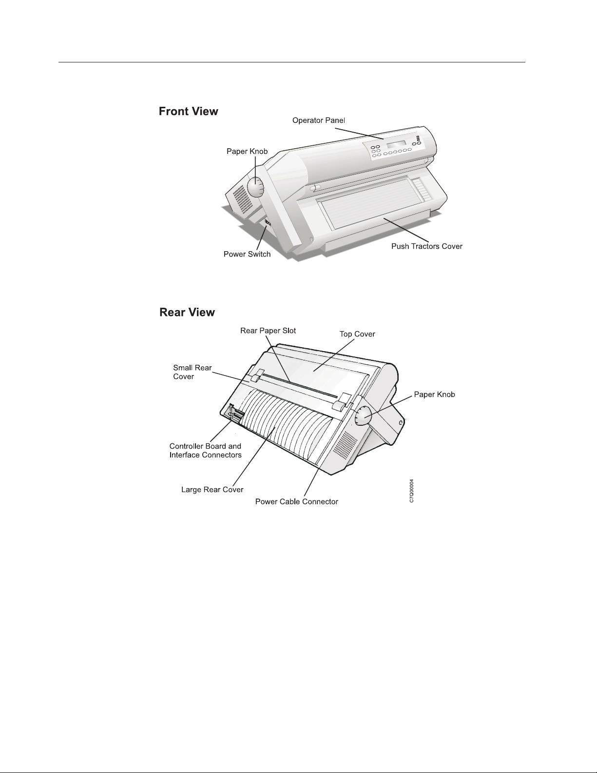
Printer parts
2 User’s Guide
Figure 1. Printer Parts: Front and Rear View
Page 19
Unpacking the printer
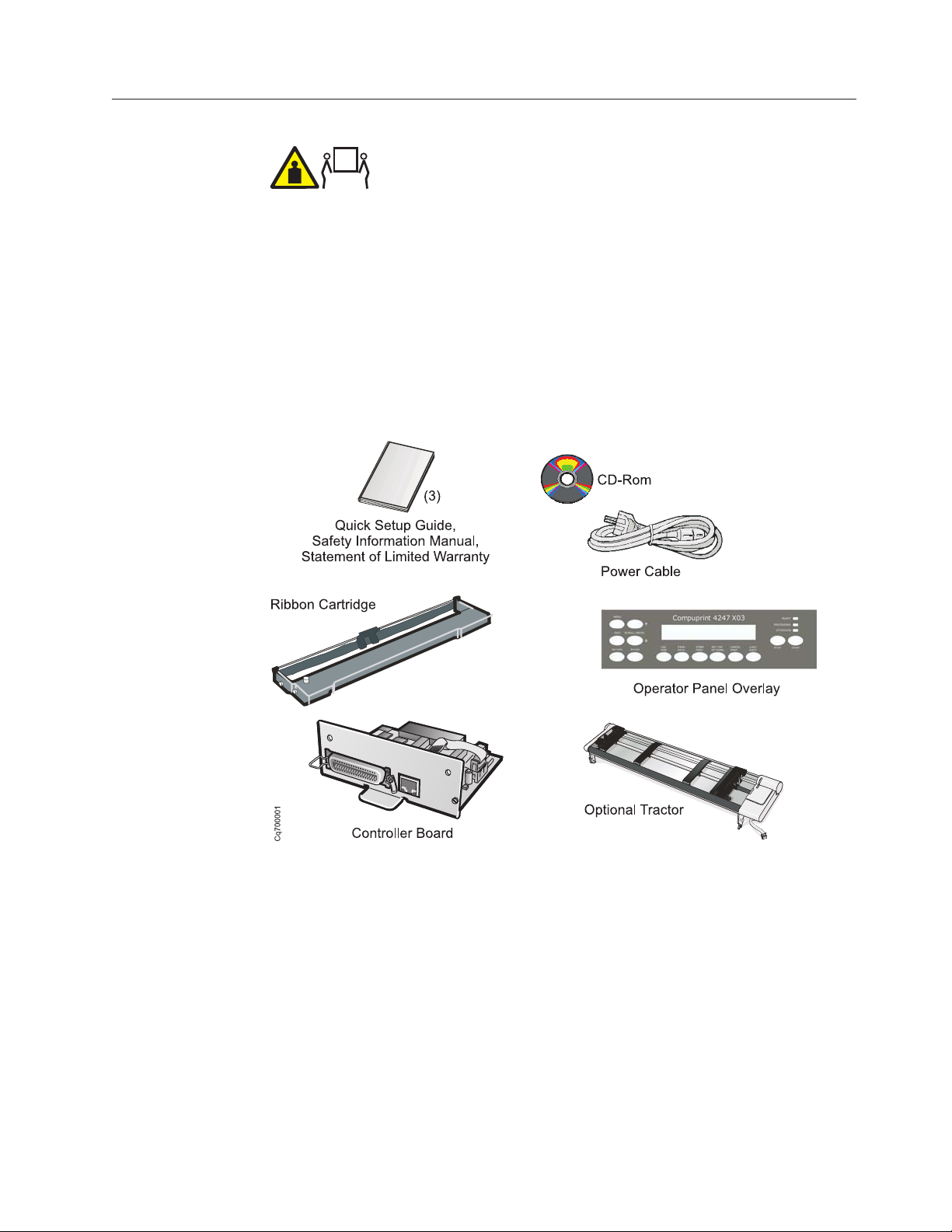
1. Review the following list of contents as you unpack the shipping container.
Contact your point of purchase if any items are missing.
__ v Printer
__ v One forms tractor (and optional second tractor)
__ v Ribbon cartridge
__ v Documentation and CD
__ v Controller Board (do not remove from protective package)
__ v Operator panel overlay
__ v Power cable
__ v CD Rom
CAUTION:
The 4247 printer weighs 21 kg (46 lbs). Two persons are required to lift
it.
Figure 2. Contents of Shipping Container
Additionally, you can order the following option (not pictured here).
v Printer Stand - Provides adequate printer support, and especially helpful
when using the Dual Push forms path
2. After opening the shipping container, have another person help you remove the
printer and place it on a table or the optional printer stand. If you select a table
as the permanent location, ensure:
v You have access to both the front and the rear of the printer.
v The table you select is sturdy enough to support the weight of the printer,
and firm enough to contain the action of the printer movement. To meet this
criteria, We recommend the optional printer stand which is available from
your marketing representative.
Chapter 1. Getting started 3
Page 20
3. Remove the remainder of the contents from the shipping container. (See
Appendix A, “Printer specifications” for dimensions of the table or printer
stand surface and the clearances required around the printer.)
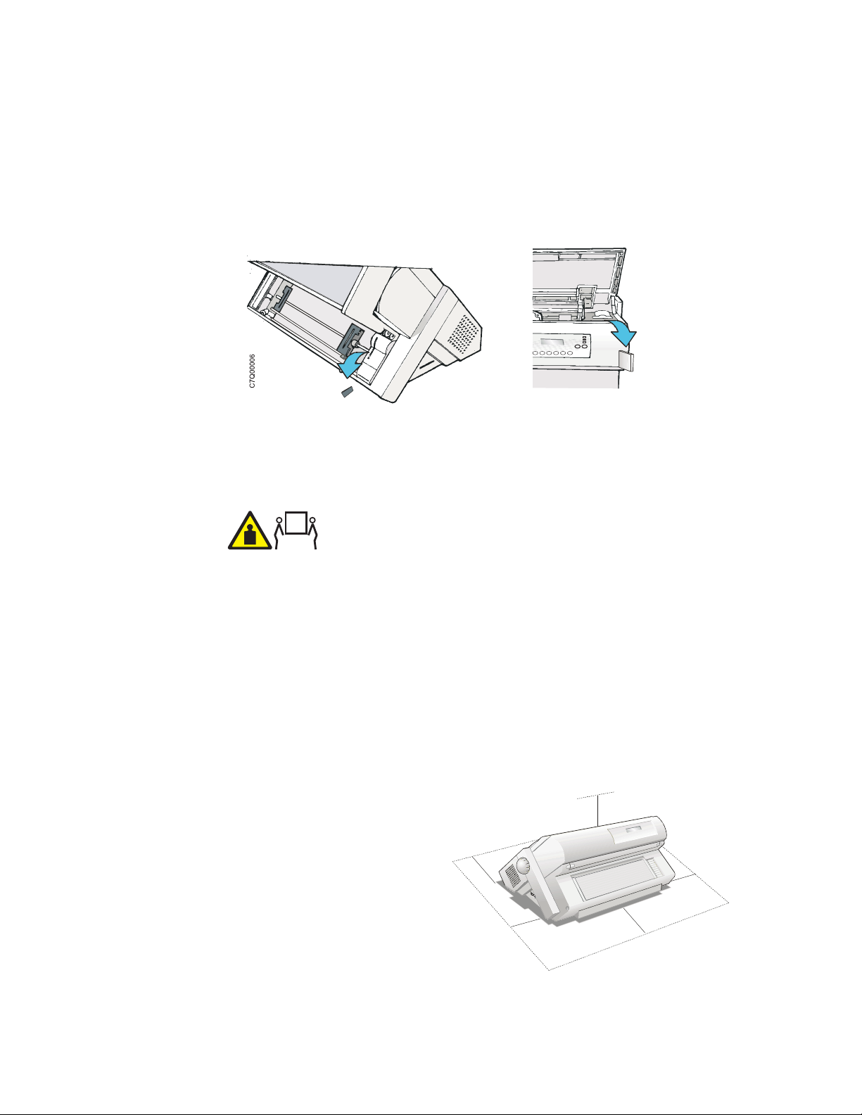
4. If you have not already done so, remove the plastic bag from the printer.
5. Lift the bottom edge of the front tractor cover into the open position.
6. Remove the shipping locks from the printer.
Figure 3. Removing the shipping locks from the printer.
Choosing a suitable location
CAUTION:
The 4247 printer weighs 21 kg (46 lbs). Two persons are required to lift
it.
Consider the following points when you choose the location for your printer:
v The distance between the printer and the host computer must not exceed the
length of the interface cable. The location must be sturdy, horizontal and stable
v Your printer must not be exposed to direct sunlight, extreme heat, cold, dust or
humidity (see Appendix A, “Printer specifications,” on page 165.
v You need a power outlet compatible with the plug of the printer's power cord.
v For best continuous forms stacking, the forms should be stacked on the floor or
on a surface below the base of the printer.
v For successful forms parking, the input forms stack must always be lower than
the base of the printer.
There must be sufficient
clearances on all sides for easy
operation. The required space is
shown in the following figure:
1
0
3
9
.
4
Hc0i0005
0
c
m
i
n
m
c
0
2
n
i
9
.
7
80 cm
31.5in.
m
c
0
2
n
i
9
.
7
1
0
3
0
9
c
.
4
m
i
n
4 User’s Guide
Figure 4. Printer clearances.
Page 21
Performing a power-receptacle safety-check
DANGER
<1-10> Hazardous voltages are present. Do not touch the pins or sockets of
the power receptacle.
For pluggable equipment, the socket-outlet shall be installed near the equipment
and shall be easily accessible.
“Portable power strip receptacles (temporary power taps)” on page xii, conforming
to all requirements, may be used.
A qualified electrician should perform all checks necessary to ensure safe
operation. These should include the following checks and any other required by
local regulations.
v Check the AC voltage at all associated power receptacles (see “4247 Model X03
nominal AC input power requirements”).
v Check the AC impedance to ground at all associated power receptacles.
Attention: If the voltages are not within the correct operating range, allow
correction before the equipment is plugged in and operated.
4247 Model X03 nominal AC input power requirements
Nominal Voltage Voltage Range Amps Phase / Hz
100–230 Vac 90–264 Vac 3.8–1.6 A Single phase /
Installing the Controller Board
The 4247 printer arrived with the Controller Board that you ordered.
You must install the Controller Board (received with the printer) into the proper
slot in the back of the printer before it can be used.
Handling the Controller Board
Attention: Do not remove the Controller Board from the protective package until
instructed to do so. Static electricity, though harmless to you, can damage sensitive
Controller Board components. Use the information in this section to avoid
damaging a Controller Board.
v Limit your movement. Your movement can create static electricity that, when
released to the Controller Board, can damage the electronic components on the
Controller Board. Sliding your foot across carpeting is an example of how you
create unwanted static electricity.
v Handle the Controller Board only by the edges and prevent others from making
direct contact with it.
v Before removing the Controller Board from the protective package, ground the
package to exposed metal at the back of the printer. This will release any static
50–60 Hz
Chapter 1. Getting started 5
Page 22
charge that may have developed on the package or on your body. Hold the
package against the metal for at least two seconds.
v When you are instructed, remove the Controller Board and install it directly into
the Controller Board slot without setting it down. If you have removed the
Controller Board from the protective package and cannot immediately insert it in
the printer, place the protective package on a flat surface, and set the Controller
Board on top of the protective package.
Inserting the Controller Board
Attention: Ensure that the printer is powered off before installing or removing
the Controller Board.
If the Controller Board is installed while the printer is powered on, the controller
will not synchronize with the printer mechanism board. Unpredictable printer
behavior will result.
Perform the following steps to install the Controller Board:
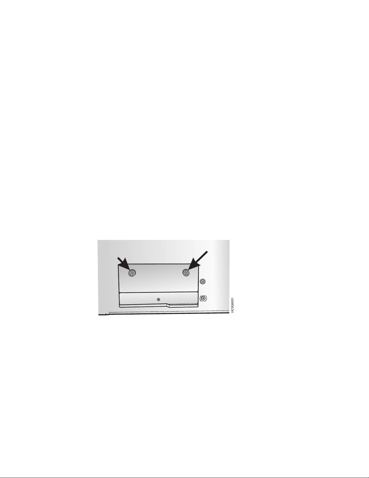
1. Ensure that the printer is powered off. Installing the Controller Board with the
printer power on will result in unpredictable printer behavior.
2. Use the screwdriver that came in the Controller Board box to remove the metal
plate on the back of the printer by unscrewing the two screws.
Note: Save the two screws as you need them to attach the Controller Board to
the back printer. Save the metal plate for reuse if the Controller Board is
removed.
6 User’s Guide
Figure 5. Removing the two screws on the metal plate.
3. Use the information under “Handling the Controller Board” on page 5 as you
remove the Controller Board from its shipping box and from the protective
package.
4. Align the left and right sides of the Controller Board with the guides in the
printer and slide it into the slot.
Page 23
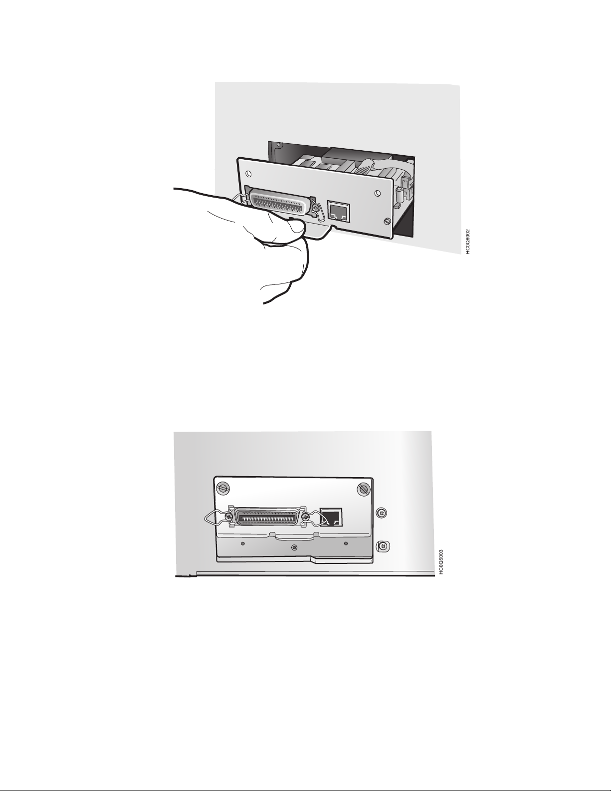
Figure 6. Sliding the board in the slot.
5. Gently push the Controller Board into the printer until it is seated in the
connector inside the printer. The Controller Board is correctly seated in the
printer when the Controller Board metal plate is aligned with the back profile
of the slot.
6. Attach the Controller Board with the two captured screws using the
screwdriver that came in the Controller Board box.
Figure 7. Attaching the Controller Board.
Chapter 1. Getting started 7
Page 24
Installing the operator panel overlay
Figure 8. Operator panel
1. Remove the protective film from the printer operator panel display.
2. Remove the paper backing from the reverse side of the operator panel overlay.
3. Align the bottom of the overlay and align both sides. Ensure that the placement
you choose for the overlay will allow free movement of the operator panel
keys.
4. After being satisfied with the placement, press the overlay in place starting at
the bottom below the keys, and continue working upwards until the overlay is
pressed into place.
8 User’s Guide
Page 25
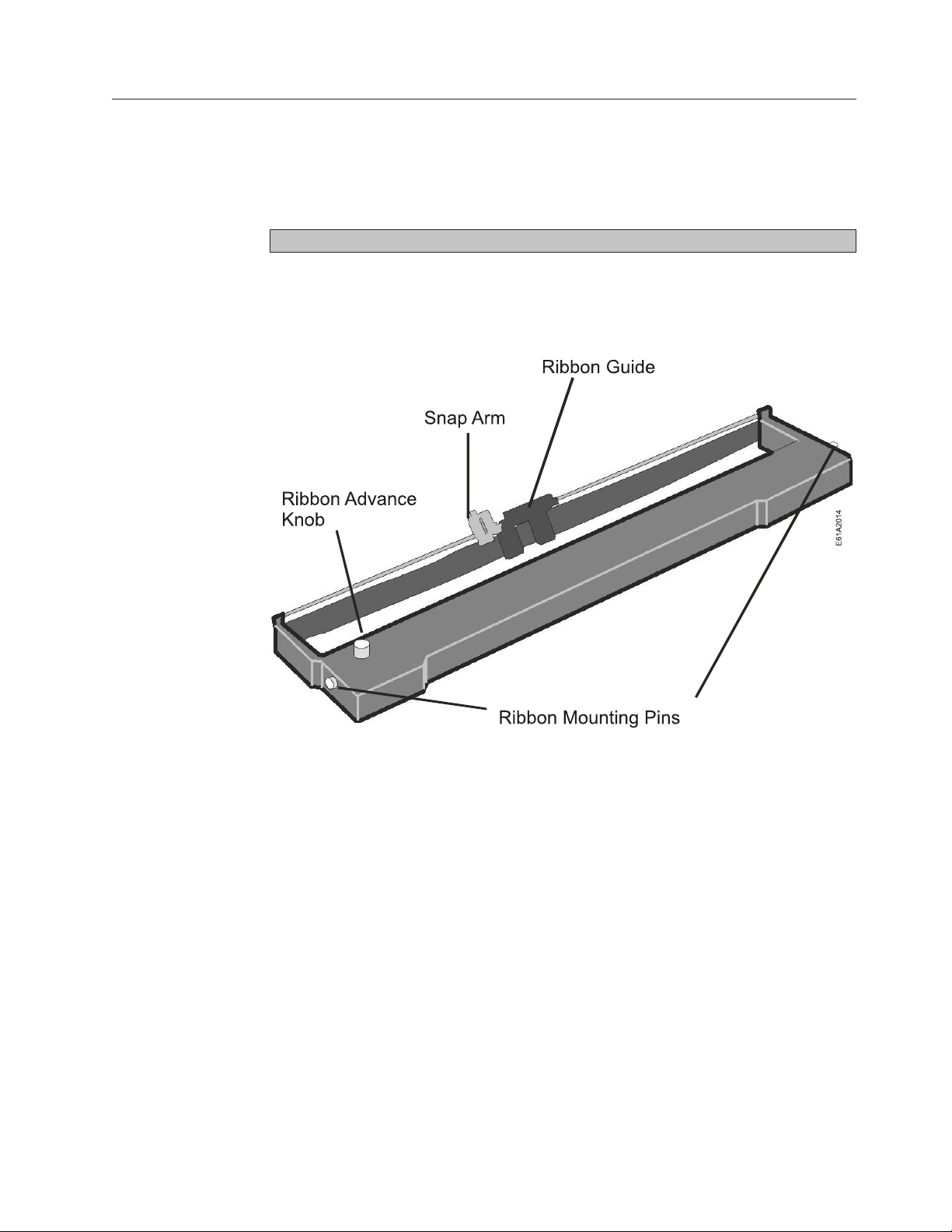
Installing the ribbon cartridge
It is recommended that you use an approved ribbon cartridge. To install the ribbon
cartridge, follow these steps:
1. Remove the ribbon cartridge from the package. Locate the ribbon guide, snap
arm, ribbon advance knob, and the ribbon mounting pins.
To avoid damage to the ribbon, do not turn the winding knob in the wrong direction.
2. Turn the ribbon advance knob in the direction of the arrow to take up any
slack in the ribbon. If the ribbon does not move, contact your place of ribbon
purchase to replace the ribbon cartridge.
Figure 9. Ribbon Cartridge
Chapter 1. Getting started 9
Page 26
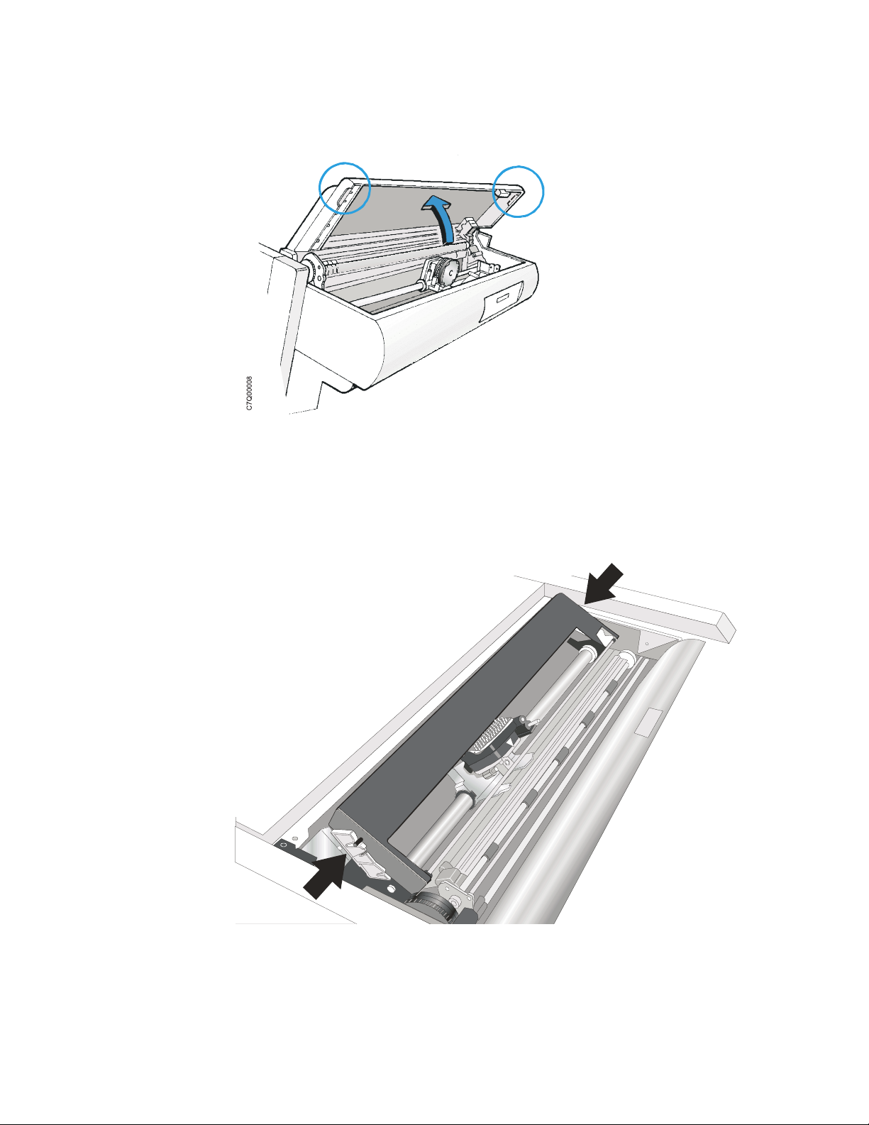
3. Open the top cover using the small handles on either side of the top cover.
Figure 10. Opening the top cover
4. Slide the print head to the center of the printer.
5. Align the cartridge pins with the locking grooves on the left and right
cartridge supports.
10 User’s Guide
C7Q02016
Figure 11. Aligning the cartridge pins.
Page 27
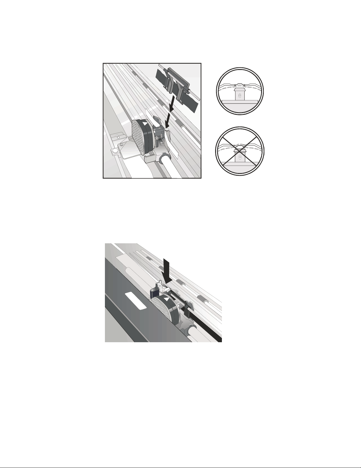
6. Position the ribbon guide over the printhead, holding it perpendicular to the
print head.
HC0I0030
Figure 12. Print head and ribbon guide mask showing correct positioning of the ribbon.
7. Turn the ribbon advance knob to take up any slack in the ribbon.
8. Position the snap arm with the small lever up onto the ribbon lift assembly.
Push the snap arm down onto the ribbon lift assembly until it snaps into
place.
Figure 13. Positioning the snap arm.
e61a2018
Chapter 1. Getting started 11
Page 28
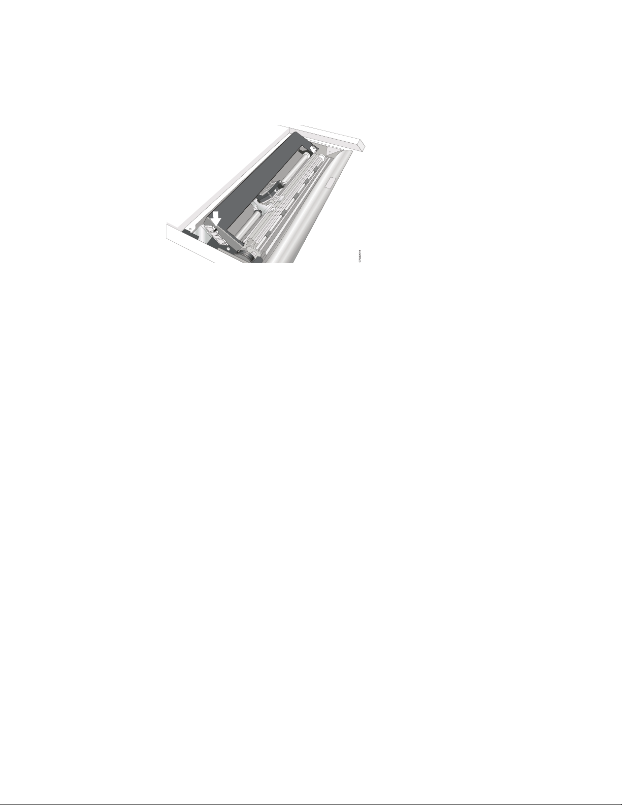
9. Align the ribbon mounting pins on the left and right side of the ribbon
cartridge with the slots in the cartridge supports. Snap the ribbon cartridge
down into place.
Figure 14. Aligning the ribbon mounting pins.
10. Turn the ribbon advance knob again in the direction of the arrow to take up
any slack in the ribbon, as you slide the printhead back and forth to ensure
that the ribbon guide runs freely along the ribbon.
11. If the ribbon is not running freely, or to ensure that you have installed the
ribbon cartridge correctly, ensure that:
a. The left and right ribbon mounting pins are securely snapped into the
cartridge supports.
b. There are no twists or folds in the ribbon.
c. The ribbon is not catching on the printhead.
d. The ribbon moves when you turn the ribbon advance knob in the direction
of the arrow. If the ribbon does not move, replace the ribbon cartridge.
Contact your place of ribbon cartridge purchase if you believe that the
ribbon is faulty.
12. Close the top printer cover.
Removing the ribbon cartridge
12 User’s Guide
See “Removing the ribbon cartridge” on page 149 for instructions on this
procedure.
Page 29
Power connection
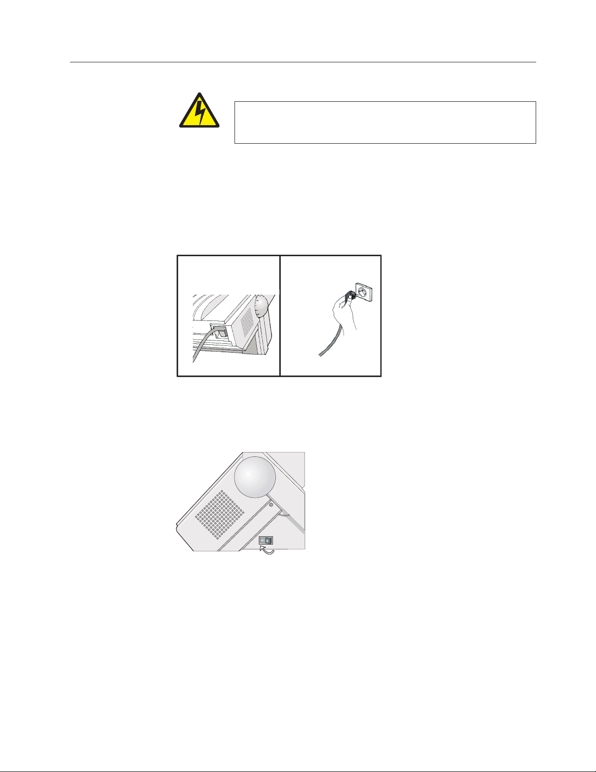
1. Make sure the power outlet is near the printer location and easily accessible.
2. Make sure that the power switch is in 0 position (OFF).
3. Insert the power cable plug into the printer connector and the other power
DANGER
<1-11> Your country may require an approved power cord and plug.
Ensure that you have the correct power cord and plug. Use this cord
and plug only with an approved, correctly-installed power receptacle.
cable end into a convenient outlet.
12
HC0I0014
Figure 15. Inserting the power cable plug
4. Turn the printer on, press the power switch in the I position (ON).
HC0I0015
Figure 16. Power switch in the I position (ON).
Attention: If, for any reason, the Controller Board was not correctly installed in
the printer, the printer will not work and the following audio/visual symptoms
will occur:
v The buzzer sounds continuously
v The Operator Panel display is partially filled with solid black boxes
v The Operator Panel LEDs are all lit.
If this is the case, power off the printer, re-seat the Controller Board, and power
the printer on again.
Chapter 1. Getting started 13
Page 30

Note: If the printer does not show the correct display sequence, go to the status
code section of “Using status code and problem listings” on page 151.
Follow the instructions for the status code shown on the display panel.
14 User’s Guide
Page 31

Changing the display language (from English)
The printer is delivered with English as the default language. Follow this
procedure to change the language in which messages and menu items will appear
in the operator panel display.
1. Press MENU to enter configuration.
2. Press SCROLL/MICRO
CONFIGURATION MENU
Display Language
3. Press ENTER to display the current value.
4. Press SCROLL/MICRO
is displayed.
5. Press ENTER. An asterisk (*) will be displayed in front of the selected value.
6. Press RETURN to return to the Configuration Menu.
7. Press START. The printer displays:
Press ENTER to Save
Press START to Not Save
8. Choose between one of these options:
v If you want to use the selected display language as the printer default for
this session only (the printer will use the existing defaults the next time it is
powered on), press START. The printer will exit the menu and become
ready.
v OR
v If you want to keep the selected display language as the printer default,
press ENTER. The printer displays:
or SCROLL/MICRO until the printer displays:
or SCROLL/MICRO until the language you want
Save Current Values
Custom Set A
9. Press ENTER.
10. Press START again. The printer will exit the menu and become ready.
Chapter 1. Getting started 15
Page 32

Loading forms in the Front Push Tractors
This sequence describes how to load the fanfold paper with the push tractor
(default).
1. Turn the printer on.
2. Open the Push tractors cover turning it upwards and lay it on the top of the
printer.
Figure 17. Opening the Push tractors cover
3. Unlock the tractors by moving the sprocket levers to the up position. Slide the
left tractor to the left.
Figure 18. Unlocking the sprockets of the Front1 push tractor
16 User’s Guide
Page 33

4. Space the paper guides along the tractor bar. Open the left and right sprocket
covers.
HC0I0019
Figure 19. Opening the left and right sprocket covers.
5. Hold the fanfold paper in front of the sprockets and insert the paper
perforation on the left sprocket pins and close the left sprocket cover.
Figure 20. Closing the left sprocket cover.
Chapter 1. Getting started 17
Page 34

6. Insert the paper on the right sprocket pins.
HC0I0022
Figure 21. Inserting the paper on the right sprocket pins.
7. Match the left sprocket for the first printing position, that is the left margin
must match the 9
Note: Aligning the left-hand edge of the paper past the 22
th
mark on the printer cabinet.
nd
spacer on the
printer cabinet will cause the paper to be misaligned with the Paper
Load Sensor resulting in a '001 End of Forms' error.
9
1
345678
2
HC0I0023
18 User’s Guide
Figure 22. Matching the left sprocket for the first printing position.
Page 35

8. Adjust the right sprocket gently to remove slack from the paper. Lock the left
and right sprockets moving the sprocket levers to the up position.
HC0I0025
Figure 23. Adjusting the right sprocket
9. Close the Push tractors cover.
HC0I0026
Figure 24. Closing the Push tractors cover.
10. Press the STOP key to take the printer Not Ready.
11. Press the LOAD/EJECT key to load the paper into the printer.
12. Press the START key to put the printer READY.
Printing your first documents
The Quick Reference is a popular print test that may help familiarize you with the
operator panel keys and the configuration menu you can set. The Quick Reference
printout allows you to check print quality and printer operations.
v Each key is listed with a corresponding description to the right.
v Each parameter is shown with the corresponding values you can select printed
to the right.
1. Ensure that the printer is offline. If the printer is ready, press STOP to make the
printer not ready.
2. Press TEST.
3. Press SCROLL/MICRO
or SCROLL/MICRO until the printer displays:
Chapter 1. Getting started 19
Page 36

OPERATOR PRINT TESTS
Quick Reference
4. Press ENTER or START to print this test. The READY indicator comes on and
printing begins. Press STOP if you want stop the Print Test before it completes
printing.
5. Wait for the printer to stop printing and the READY indicator to go off.
6. Press FORM FEED until you can remove the printout. The printout should be
clear and readable.
YOU HAVE JUST COMPLETED A SETUP AND CHECKOUT OF THE PRINTER.
We recommend that you now print your printer configuration defaults. Save this
printout for future reference. You can create a printout of the printer configuration
by following these steps:
1. Press SCROLL/MICRO
OPERATOR PRINT TESTS
Print Custom Sets
or SCROLL/MICRO until the printer displays:
2. Press ENTER or START to print this test. See “Print Custom Sets” on page 141
for more information about this printout.
3. To exit Print Test, press RETURN to make the printer not ready or CANCEL
PRINT to make the printer ready.
Installing the optional second tractor
A second optional tractor is available for your printer. This tractor may be installed
on the first (standard) front tractor.
1. Open the tractor area cover.
Figure 25. Opening the tractor area cover.
20 User’s Guide
Page 37

2. Unpack the second tractor.
C7QU2023
Figure 26. Second tractor
3. Align the hooks on both sides of the second tractor with the pins on the first
tractor. Push the second tractor on the pins until it is fully engaged.
Figure 27. Aligning the second tractor hooks.
C7Q02024
Chapter 1. Getting started 21
Page 38

4. Connect the second tractor to the first using the electrical cable/connector
provided on the tractor.
C0Q02025
Figure 28. Connecting the second tractor
5. Rotate the tractor gear protection cover downwards to free the gear.
22 User’s Guide
C7Q02026
Figure 29. Rotating the tractor gear protection cover.
Page 39

6. Rotate the second tractor into the closed operating position.
C7Q02027
Figure 30. Second tractor in the closed position.
7. To load paper onto the first tractor when the second tractor is installed, rotate
the second tractor out and insert paper between the two tractors. (See “Loading
forms in the Front Push Tractors” on page 16 for paper loading procedures.)
Figure 31. Paper path direction
Chapter 1. Getting started 23
Page 40

Removing the optional second tractor
If you need to remove the second optional push tractor, turn the printer off.
1. Disconnect the connector cable and press on the push buttons on either side to
disengage the tractor. Then pull the tractor off.
Figure 32. Disconnecting the second tractor.
CAUTION:
<2-53> If the second tractor unit is not installed, make sure the gear protector
cover is closed. Do not touch inside the printer or insert any object into the
gears.
e61a2028
2. Close the tractor gear protection cover.
Figure 33. Closing the protection cover.
24 User’s Guide
Page 41

Attaching the 4247 Printer to your computer
Connect the printer to your host computer using the interface on the Controller
Board (supplied in the printer box) you installed in the printer.
There are three types of Controller Boards:
1. Controller Board with a bidirectional IEEE1284 parallel interface, Serial
RS232/C 9-pin interface and USB 2.0 interface.
2. Controller Board with a bidirectional IEEE1284 parallel interface and ASCII
Ethernet 10/100 BaseT LAN interface.
3. Controller Board with a bi-directional IEEE1284 parallel interface and
ASCII-IPDS Ethernet 10/100 BaseT LAN interface.
DANGER
<1-14> Switch off printer power and unplug the printer power cord
before connecting or disconnecting a communication port, a teleport, or
other attachment connector.
Insert the host computer cable(s) into the back of the printer as shown below:
Controller Board with parallel interface and
ASCII-IPDS Ethernet 10/100 LAN interface.
Completing printer setup
Your 4247 Printer is now ready to use with the forms tractor mounted in the Front
Push position and with the configuration parameters set to manufacturing defaults.
The exception is that you have selected new defaults for display language.
To select any of the other 4247 paper paths, or to change printer configuration
parameters, see:
v Chapter 2, “Understanding the operator panel” for information on operating the
printer.
v Chapter 3, “Checking and changing configuration parameter values” for
configuration information.
v Chapter 16, “Dual push tractor forms paths” for forms loading procedures.
Controller Board with parallel interface,
Serial interface, and USB interface.
Chapter 1. Getting started 25
Page 42

Software driver selection
See Appendix C, “Printer driver support,” on page 175 for information about
selecting printer drivers.
26 User’s Guide
Page 43

Chapter 2. Understanding the operator panel
Status indicators .............27
READY...............27
PROCESSING ............28
ATTENTION .............28
Display panel..............28
Audible alarm .............29
Custom Set In-Use Indicator .........29
Function Keys .............29
MENU ...............30
SCROLL/MICRO↑ or SCROLL/MICRO↓ ...30
Adjusting forms ...........31
Scrolling through categories, parameters,
values, and tests ...........31
ENTER ...............31
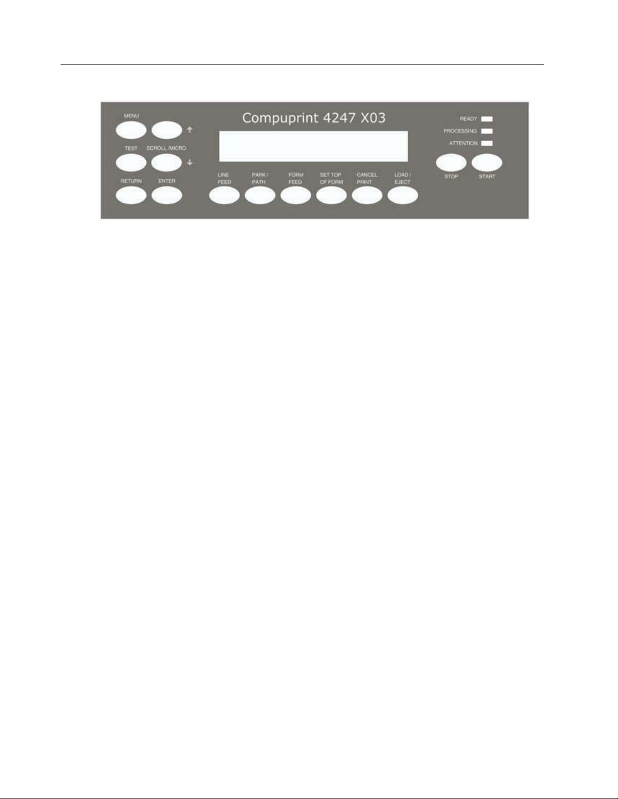
This chapter describes the function of the operator panel. The operator panel
contains 3 status indicators, a 2-line by 24-character display panel, 14 printer
function keys, and an audible alarm. Figure 34 illustrates the operator panel and
keys for the printer.
ENTER function ...........31
RETURN ..............32
RETURN function ..........32
PARK/PATH .............32
PARK function ...........32
PATH function ...........32
LINE FEED .............33
LOAD/EJECT ............33
FORM FEED .............34
SET TOP OF FORM ..........35
START...............35
STOP...............35
CANCEL PRINT ...........36
TEST ...............36
Figure 34. 4247 Printer Operator Panel
Status indicators
The following status indicators appear on the operator panel:
v READY
v PROCESSING
v ATTENTION
You can determine printer status by checking these indicators.
READY
If the READY indicator is lighted, the printer is ready to print. If READY is not
lighted, the printer is not ready to print. The printer can receive data when this
indicator is not lighted, but no data can be printed.
The Ready indicator is lighted because of one of the following conditions:
v Successful power-on sequence
v After pressing START, if the indicator was off because of one of the following
conditions:
– An error condition (if the error has been corrected)
27
Page 44

– An intervention required condition (if the error has been corrected)
– After pressing STOP
v After pressing ENTER or START to run a test in the Operator Print Tests menu
v After a successful partial reset to ready after pressing CANCEL PRINT to exit
the Operator Print Tests
The READY indicator is not lighted because of one of the following conditions:
v After pressing STOP
v After detection of an intervention required condition
v After detection of a printer error
v After pressing MENU to enter the Configuration Menu when no print job is in
progress
v After pressing LOAD/EJECT to perform an eject to tear off position when Front
Push or Rear Push is selected.
PROCESSING
If lighted, the printer is printing or processing data. If blinking, the printer buffer
contains data that cannot be printed immediately. If not lighted, there is no data to
process and no data in the print buffer.
ATTENTION
If blinking, the printer requires operator intervention (for example, to add forms or
to clear a forms jam). The type of intervention needed appears on the display
panel. If not lighted, the printer does not require immediate attention.
Display panel
The display panel is a 2-line by 24-character liquid crystal display (LCD) that
displays printer status messages, the print test menu, and the configuration menu
categories, parameters, and values. Use this display panel and the printer function
keys to scroll through and select Configuration Menu items and Operator Print
Tests. You can set this display so the messages appear in one of the following
languages:
v 000 English (default)
v 001 Deutsch
v 002 Français
v 003 Italiano
v 004 Español
v 005 Nederlands
v 006 Dansk
v 007 Português
v 008 Norsk
v 009 Svenska
v 010 Suomi
v 011 Polski
28 User’s Guide
Page 45

Audible alarm
If you do not disable the audible alarm, it beeps if any of the following conditions
occur:
v Immediate intervention is required
v A printer error condition exists
v The printer receives a command from the host to turn on the alarm
v An invalid key press is attempted
v The SET TOP OF FORM key is pressed
To turn a beeping alarm off, press STOP. You can disable the audible alarm. See
“Alarm control” on page 66 for instructions.
Note: Pressing SET TOP OF FORM and some attention conditions sound the
alarm, even if it is disabled.
Custom Set In-Use Indicator
This indicator shows the parameter custom set that is currently being used by the
printer. The indicator is located in the top right corner of the operator panel. A
custom set is a set of configuration values that have been defined at the operator
panel and saved under a letter ID. When the custom set identified by this ID is
selected from the operator panel, these configuration values are used by the
printer.
Function Keys
NOT READY <X>
The current custom set in use is displayed in parentheses <X>. Where <X> can be:
A (Custom Set A in use)
B (Custom Set B in use)
C (Custom Set C in use)
D (Custom Set D in use).
E (Custom Set E in use)
F (Custom Set F in use)
G (Custom Set G in use)
H (Custom Set H in use).
If a change was made in the configuration menu and not saved in a custom set,
then the change is temporary and a blank < > is displayed in the parentheses. For
more information on Custom Sets, see Chapter 4, “Configuration storage.”
There are 14 keys available on the operator panel for performing printer functions.
These keys perform general printer functions (for example, adjusting forms) and
are used to scroll through and select items in the Configuration Menu and
Operator Print Tests menu.
The following section describes each of the printer function keys on the operator
panel.
Chapter 2. Understanding the operator panel 29
Page 46

MENU
Use the Menu function key to enter the Configuration Menu. This function key is
valid when the printer is not ready or the printer is ready and no job is in progress.
After you enter the Configuration Menu, paper movement functions are not
available.
Press MENU to enter the Configuration Menu.
The printer displays:
CONFIGURATION MENU
Configuration Storage
Note: If a print job is in progress (the printer is printing or the PROCESSING
indicator is on), the printer displays:
009 INVALID KEY PRESS
PRESS STOP FIRST
In this case, you can press STOP first and then enter the Menu. However, it is not
recommended that you change the Configuration Parameter Values while a print
job is in progress.
The configuration menu can be locked to prevent an unauthorized user from
changing parameter values. When the configuration menu is locked, pressing the
MENU key only allows recall of Custom Set Values. The Printer Adjustments in
the Operator Print Tests Menu are disabled.
If the MENU is locked, the printer displays:
097 FUNCTION DISABLED
MENU LOCKED
For more information on the Menu Lock function, see your system programmer or
the 4247 Model X03 Printer Programmer Manual.
For more information on configuration parameters and values, see “Checking and
changing parameter values” on page 38.
SCROLL/MICRO↑ or SCROLL/MICRO↓
Use SCROLL/MICRO or SCROLL/MICRO to perform the following functions:
v Adjust forms upward or downward when the printer is not ready.
v Scroll through the Configuration Menu categories, parameters, and values.
v Scroll through the Operator Print Tests menu items.
30 User’s Guide
Page 47

Adjusting forms
Press SCROLL/MICRO or SCROLL/MICRO to move the form 0.176 mm
(1/144 in.) in the direction of the arrow each time you press the key. If you
continue to hold down the SCROLL/MICRO key, the forms move continuously
until you release the key.
When the printer is at the top of the forms and the SCROLL/MICRO keys are
used, the new forms position is now the top of forms.
Note: If you use these keys when the PROCESSING indicator is blinking, the top
of form position could become misaligned.
Scrolling through categories, parameters, values, and tests
The scrolling functions are available only when the Configuration Menu or Test
Menu is displayed.
ENTER
Pressing SCROLL/MICRO
the second line of the display to show the previous configuration category,
parameter, or value. Pressing SCROLL/MICRO
displayed changes the second line of the display to show the next configuration
category, parameter, or value.
Pressing SCROLL/MICRO
line of the display to show the previous test name. Pressing SCROLL/MICRO
when the Test Menu is displayed changes the second line of the display to show
the next test name.
The scroll keys also enable the selection of numeric values. The list of numeric
values starts with the lowest value. When a numeric value is to be entered, use
SCROLL/MICRO
SCROLL/MICRO
second line of the display panel. When the value you wish to select appears, press
ENTER.
The scrolling functions are also used during some of the Operator Print Tests. See
Chapter 17, “Using the Operator Print Tests” for more information.
to see the next lower value in the range and
to see the next higher value. The values are shown on the
when the Configuration Menu is displayed changes
when the Configuration Menu is
when the Test Menu is displayed changes the second
ENTER function
The Enter function is available when the Configuration Menu or Operator Print
Tests Menu is displayed.
Pressing ENTER selects the displayed option.
The Enter function is also used during some of the tests.
Chapter 2. Understanding the operator panel 31
Page 48

RETURN
RETURN function
Pressing RETURN in the Configuration Menu returns to the previous level of the
menu, unless the printer already displays:
CONFIGURATION MENU
Configuration Storage
If Configuration Menu is displayed, the printer exits the menu and becomes not
ready.
Note: If you have made configuration changes and have not saved them in a
PARK/PATH
Custom Set, the display will prompt you to save the changes. If you are in
the Operator Print Tests Menu and a test is not running, pressing RETURN
will exit the Test Menu and make the printer not ready.
PARK function
Pressing this key causes the printer to enter the Park function in either the ready
and not ready state. The continuous forms will back up (reverse the process
direction of) the forms in the forms path.
If continuous forms are currently in the printer and the top of the form is beyond
the print area, press PARK/PATH. The forms will be ejected for tearoff and the
printer will display:
091 FANFOLD PARK
TEAR OUTPUT PRESS PARK
If special forms are currently in the printer that cannot be moved backwards (for
example, labeled continuous forms), the printer displays:
092 FANFOLD PARK
TEAR INPUT PRESS EJECT
Perform the action requested on the operator panel display. The printer is then
ready for the paper path selection.
PATH function
When no forms are in the current path and the printer is in the not ready state,
pressing PARK/PATH allows the selection of the different forms paths available on
the printer. When the desired path is displayed, press START. The forms path
displayed becomes the active forms path and the printer becomes ready. You can
also press LOAD/EJECT or FORM FEED for continuous forms to select the active
forms path.
32 User’s Guide
Page 49

The forms path selected by PARK/PATH also becomes the current value for Paper
Source in the Printer Setup category. See “Paper Source” on page 101.
LINE FEED
This function is valid only when the printer is not ready.
Press LINE FEED to cause the printer to advance the forms one print line, based
on the current LPI setting. If you hold LINE FEED more than four seconds, the
forms move continuously until you release the key.
Similar to the forms advance knob on other printer products, the LINE FEED key
allows coarse vertical movement of forms. This key does not function as an
“Index” key, which may be found on other printer products.
Note: If you use this key when the PROCESSING indicator is blinking, the top of
form position could become misaligned.
LOAD/EJECT
The LOAD/EJECT function depends on what active form path you have selected.
This section describes the function for each of the paper paths.
The LOAD/EJECT key performs the following functions:
v Automatically loads forms
After the forms are loaded under the sensor and onto the tractors at the bottom
of the forms device press LOAD/EJECT to automatically load the forms to the
top of form position.
v Moves forms to the tear-off position
Do not press STOP first.
If a Form Feed is done, either by data stream command or by pressing FORM
FEED, prior to pressing LOAD/EJECT, the forms will be positioned for you to
tear off the forms at a perforation.
Note:
If pressing LOAD/EJECT did not align the forms perforation with the tear
bar, check the following:
1. Assure that a Form Feed has been done just prior to pressing
LOAD/EJECT.
2. Verify that the Tear Position value for the path you are using (Front or
Rear) in the Printer Adjustments section of the Configuration Menu
has been set correctly. Often this value is the negative of the Paper
Load Position value. Adjust the Tear Position to give the best
alignment of the forms perforation to the tear bar edge. Each path has
its own set of adjustment values. When you change these values,
ensure that you are setting the values for the desired path.
Chapter 2. Understanding the operator panel 33
Page 50

If you specify Immediate Eject for Continuous Forms Eject Mode parameter
(default value) in the Printer Setup category, press LOAD/EJECT to immediately
make the printer not ready. The printer displays:
003 FORMS EJECTED
PRESS LOAD
and advances the form so that you can tear off the form at the perforation and
remove it from the printer.
If you specify Delayed Eject for the Continuous Forms Eject Mode parameter in
the Printer Setup category, press LOAD/EJECT to cause the printer to display:
093 EJECT PENDING
and beep the alarm. When the end of the form is reached, the printer becomes
not ready, displays:
003 FORMS EJECTED
PRESS LOAD
and advances the form so that you can tear off the form at the perforation and
remove it from the printer.
Pressing the key a second time moves the next form to be printed back to the
previous print position and makes the printer ready.
Refer to “Continuous Forms Eject Mode” on page 109 for more information on
changing Continuous Forms Eject mode.
v Ejects forms for viewing
If a Form Feed is not done prior to pressing LOAD/EJECT, the forms will be
positioned for you to view them to examine the printing
FORM FEED
This key advances the forms so that the next form is at the top of form position.
The Form Feed function is available when the printer is not ready.
v If you interrupt a print job by pressing STOP, pressing FORM FEED, and then
pressing START (when you are ready to resume the job), the printer continues
to print on the next form at the place where printing was interrupted on the
previous form.
v If FORM FEED is pressed during Front Push or Rear Push load operation, the
FORM FEED functions as a LOAD/EJECT and performs an automatic load.
v The printer does not always have to be not ready before pressing FORM FEED.
See “Form Feed Mode” on page 105 for more information.
34 User’s Guide
Page 51

SET TOP OF FORM
This should only be used when printing occurred and no Top-of-Forms commands
have been passed to the printer (such as Form Feed or Printer initialization).
The Set Top of Form function is available only when the printer is not ready, and
the paper is loaded to the print line. This key can be used only for the continuous
forms paper sources.
Press SET TOP OF FORM to set the top of form position for continuous paper
sources only. The alarm beeps and the printer displays:
TOP OF FORM SET
while you hold down the SET TOP OF FORM key.
If preprinted forms are being used, use Paper Load Positioning (see Chapter 9,
“Printer adjustments,” on page 115) instead of Top-of-Form.
START
STOP
Press START to perform the following functions:
v Make the printer ready and cause the READY message to appear in the operator
panel display.
v Exit the Configuration Menu and make the printer ready. If a partial reset is
required, it is performed to put configuration changes into effect before the
printer becomes ready.
Note: If you have made configuration changes and have not saved them in a
Custom Set, the display will prompt you to save the changes.
v Start the printer printing if no error condition appears on the display and if the
computer is sending data to be printed.
v Begin a test from the Operator Print Tests menu.
If the printer is in a ready state, press STOP to:
v Make the printer not ready and cause the READY message to disappear from the
operator panel display
v Stop printing as soon as possible without losing print data
v Stop a test if the printer is in test mode
v Stop the printer alarm from beeping
v Allow you to use the other printer function keys
v Cause the printer to display:
Chapter 2. Understanding the operator panel 35
Page 52

NOT READY <X>
(or cause the current test menu to display if the printer is in Operator Print Tests
mode)
If an error condition appears on the operator panel display, press STOP to:
v Clear the error message from the display
v Stop the printer alarm from beeping.
CANCEL PRINT
When this key is pressed while the printer is active and online, the attachment
sends a “cancel request” to the host the printer displays:
059 CANCEL PRINT ACTIVE
For any attachment option, the CANCEL PRINT button clears all print data and
buffers. This function is valid only when the printer is not ready.
CANCEL PRINT is also active in Operator Print Tests. If CANCEL PRINT is
pressed while in the tests, the printer stops any test in process, exits the test mode,
performs a partial reset, and becomes ready.
TEST
Press TEST to enter the Operator Print Tests menu. The Test function is valid only
when the printer is not ready.
There are several tests available. After you press TEST, the printer displays:
OPERATOR PRINT TESTS
Quick Reference
Press SCROLL/MICRO or SCROLL/MICRO to display the other available tests.
Refer to Chapter 17, “Using the Operator Print Tests,” on page 139 on selecting and
running tests.
36 User’s Guide
Page 53

Chapter 3. Checking and changing configuration parameter values
Printing configuration defaults ........37
Checking and changing parameter values ....38
Exiting the Configuration Menu .......39
Exiting using START ..........39
Exiting using RETURN .........39
Locking the Printer Configuration Menu.....40
Configuration categories ..........40
Configuration storage ..........41
Attachment .............41
IPDS Configuration ...........41
This chapter gives you brief descriptions and procedures for checking or changing
the Configuration Parameter Values. Parameter values are settings the printer
recognizes and uses to process print data. These values can be set using the
operator panel. They are grouped together into categories of values and are
accessed on the operator panel by these categories. These categories are available
on the Configuration Menu:
v Configuration Storage
v Attachment
v IPDS Configuration
v ASCII Configuration
v Printer Setup
v Printer Adjustments
v Power On Reset
v Display Language
v Vital Product Data
v Quiet Print
v Hex Print
v Quit From Menu
ASCII Configuration ..........42
Printer setup .............45
Printer adjustment ...........46
Power On Reset ............46
Display language ...........47
Vital Product Data ...........47
Quiet Print .............47
Hex Print ..............48
Quit From Menu ...........48
You can use the Configuration Parameter Values set at the manufacturer, or you
can change them. Instructions for checking and changing the Parameter Values for
each of these Configuration Categories are described in this section.
Notes:
1. The computer program can override Parameter Values that you select from the
operator panel. The values that the computer program cannot override are
listed in “Configuration categories” on page 40.
2. If a category or parameter that is not valid for your printer application is
displayed, you should ignore it; it will not harm the printer or affect its
operation.
3. We recommend that you print your custom sets for reference. See “Printer
Configuration” in Chapter 17, “Using the Operator Print Tests” for information.
Printing configuration defaults
We recommend that you print your configuration values and save this printout for
future reference. See “Printer Configuration” on page 141 for information on
printing your printer configuration values.
37
Page 54

Checking and changing parameter values
Checking and changing Configuration Parameter Values is done in the
Configuration Menu, which is entered with the MENU key. The Configuration
Menu is divided into three levels:
v Category
v Parameter
v Value
Note: Do not change Parameter Values during a print job; data may be lost.
Press MENU to enter the Configuration Menu.
CONFIGURATION MENU
Configuration Storage
The first category in the Configuration Menu is listed on the second line of the
display. Use SCROLL/MICRO or SCROLL/MICRO to scroll through the
Categories until the category you want is displayed. Press ENTER to display the
first Parameter in the Category you select. Use SCROLL/MICRO
SCROLL/MICRO
to check or change is displayed. Press ENTER to display the current value for the
selected Parameter (indicated by an asterisk [*]).
to scroll through the Parameters until the parameter you want
or
Use SCROLL/MICRO
available Values until the value you want is displayed. Press ENTER to select this
new value.
When you change the values and do not save them in a custom set, the printer
retains the values until one of the following occurs:
v You power off (O) the printer
v You change the values again
Unless you save the values in a custom set, the values you changed are lost when
you power off (O) the printer. The next time you power on (|) the printer, the
values you saved previously in the Power-On Custom Set, are the values the
printer uses.
See Chapter 4, “Configuration storage” for information about saving and recalling
parameter values in custom sets.
Configuration changes do not take effect until the printer completes printing the
buffered data (data the printer has in its storage areas).
If you change a parameter (or several parameters) and then decide you do not
want to keep your changes, you can return to the previous value settings by
selecting Quit from Menu from the Configuration Menu. The printer displays
Quit from Menu
Restore Previous Values
and SCROLL/MICRO to scroll through the other
38 User’s Guide
Press ENTER to restore the previous values, exit the Configuration Menu, and
make the printer not ready. See Chapter 15, “Quit From Menu” for more
information about restoring previous values.
Page 55

Exiting the Configuration Menu
You may quickly exit the Configuration Menu and make the printer ready by
pressing START. You may also exit the menu and make the printer not ready using
the RETURN key. These two methods maintain the changes you have made to the
configuration.
Note: If you wish to cancel your changes, you may Quit from the menu; see
Chapter 15, “Quit From Menu.”
Exiting using START
If you did not make any configuration changes or you stored your changes in a
custom set, press START and the printer will exit the menu and become ready.
If you made configuration changes and did not store them in a custom set, to exit
by using START, use the following steps:
1. Press START from any level of the menu.
The printer displays
Press ENTER to Save
Press START to Not Save
2. If you do not want to store your changes (they will be lost when the printer is
turned off), press START again and the printer will exit the menu and become
ready.
3. To store your changes in a custom set, press ENTER.
4. The printer will go to the Value level of the Configuration Storage Category in
the menu and display
Save Current Values
Custom Set A
5. Press SCROLL/MICRO or SCROLL/MICRO until the desired custom set
name is displayed.
6. Press ENTER to store the current parameter values (see Chapter 4,
“Configuration storage” for more details).
7. Press START again.
The printer will exit the menu and become ready.
See “Configuration categories” on page 40 for the parameters you can change and
the manufacturing values.
Exiting using RETURN
If you did not make any configuration changes or you stored your changes in a
custom set, press RETURN and the printer will exit the menu and become not
ready.
If you made configuration changes and did not store them in a custom set, to exit
by using RETURN use the following steps:
1. If CONFIGURATION MENU is not on the first line of the display, press RETURN.
2. Press RETURN again.
The printer displays
Chapter 3. Checking and changing configuration parameter values 39
Page 56

Press ENTER to Save
Press RETURN to Not Save
3. If you do not want to store your changes (they will be lost when you power off
the printer), press RETURN again and the printer will exit the menu and
become not ready.
4. To store your changes in a custom set, press ENTER.
5. The printer will go to the Value level of the Configuration Storage Category in
the menu and display
Save Current Values
Custom Set A
6. Press SCROLL/MICRO or SCROLL/MICRO until the desired custom set
name is displayed.
7. Press ENTER to store the current parameter values (see Chapter 4,
“Configuration storage” for more details).
8. Press RETURN three times to back out of the menu.
The printer will exit the menu and become not ready.
See “Configuration categories” for the parameters you can change and the
manufacturing values.
Locking the Printer Configuration Menu
The configuration menu can be locked to prevent an unauthorized user from
changing parameter values. When the configuration menu is locked, you can recall
saved custom sets (A through H), but cannot change configuration parameter
values. The Printer Adjustments in the Operator Print Tests Menu are also
disabled.
To lock or unlock the printer configuration:
1. Press STOP.
2. Press and hold TEST, while pressing START. The printer displays
PRESS STOP-->NOT READY
Note: Do not press STOP.
3. Press SET TOP OF FORM.
Configuration categories
This section lists all the selectable values available and the manufacturing defaults
for the parameters in each configuration category.
40 User’s Guide
Page 57

Configuration storage
Table 1 lists the parameters available for the Configuration Storage Category. Refer
to Chapter 4, “Configuration storage” for detailed information on setting these
parameters.
Table 1. Configuration Storage Category
Parameters Values Default
Save Current Values Custom Set A-H N/A
Recall Custom Set Custom Set A-H N/A
Power-On Custom Set Last Used
Power-On Paper Source Front
Recall Factory Defaults Yes N/A
Note: Use Recall Factory Defaults to set all the parameters to the manufacturing default
values. See “Recall factory defaults” on page 53.
Attachment
Table 2 lists the parameters available for the Attachment Category. Refer to
Chapter 5, “Attachment options,” on page 55 for detailed information on setting
these parameters
Last Used
Custom Set A-H
Front
Rear
Last Used
Table 2. Attachment Category
Parameters Values Default
Attachment Hot Port Switch, Parallel,
IPDS Configuration
Table 3 lists the parameters available for the IPDS Configuration Category.
Parameters that can be overridden by the computer are noted with a dagger (†).
Refer to Chapter 6, “IPDS Configuration,” on page 57 for detailed information on
setting these parameters
Table 3. IPDS Configuration Category
Parameters Values Default
† Characters Per Inch 10
† Lines Per Inch 6
† Maximum Print Position 001 to 227 132
† Maximum Page Length 001 to 880 066
† Print Quality DP Quality
Hot Port Switch
Serial, USB, LAN ASCII,
LAN IPDS
10
12
15
16.7
6
8
DP Quality
DP Text Quality
Near Letter Quality
Chapter 3. Checking and changing configuration parameter values 41
Page 58

Table 3. IPDS Configuration Category (continued)
Parameters Values Default
† Print Language 037 to 1149
Emulation Mode 4247
Media Size Priority Standard
Bar Code Mode High
Graphics Mode High
Alarm Control Disabled
ASCII Configuration
Table 4 lists the parameters available for the ASCII Configuration Category.
Parameters that can be overridden by the computer are noted with a dagger (†).
Refer to Chapter 7, “ASCII Configuration” for detailed information on setting these
parameters.
500 International 5
Supported Print Languages
See Table 13 on page 61.
4247
4224
4230
Alternate
Alternate
High
Low
Computer Selected
High
Low
Computer Selected
Enabled
Enabled
Table 4. ASCII Configuration
Parameters Values Default
† Characters Per Inch (CPI) 10
12
15
16.7
17.1
20
† Lines Per Inch (LPI) 6
8
† Maximum Print Position (MPP) 1 to 272 136
† Maximum Page Length (MPL) 1 to 880 66
† Perforation Skipping 0 to 879 0
† Emulation Mode 4247
2381 Personal Printer
4202 Proprinter III XL
Epson-FX
† Print Language 000-1251
Supported Print Languages
See Table 13 on page 61.
10
6
4247
437 PC (When
emulation mode is
set to 4247, 4202 III
XL, 2381); 0 USA
(When emulation
mode is set to
Epson-FX)
42 User’s Guide
Page 59

Table 4. ASCII Configuration (continued)
Parameters Values Default
† Print Quality
DP Quality
DP Quality
DP Text Quality
(When emulation mode is set to 4247,
4202 III XL, 2381)
Near Letter Quality
OCR-A
OCR-B
† Print Quality
DP Quality
DP Quality
Courier
(When emulation is set to Epson-FX)
Gothic
OCR-A
OCR-B
NLQ Typeface
Courier
Courier
Gothic
(When emulation mode is set to 4247,
4202 III XL, 2381)
Character Set PC1
PC1
PC2
Italics
Printer Compatibility 3
(Automatic LF on CR)
Printer Compatibility 4
(Automatic CR on LF)
Disabled
Enabled
Disabled
Enabled
Disabled
Disabled
(When emulation mode is set to 4247,
4202 III XL, or 2381)
Printer Compatibility 5
(Form Feed Suppression)
Disabled
Enabled
(When emulation mode is set to 4247,
4202 III XL, or 2381)
Printer Compatibility 6
(Init)
Printer Compatibility 7
(Condensed Print)
Enabled
Disabled
15
16.7
17.1
(When emulation mode is set to 4247,
4202 III XL, or 2381)
Printer Compatibility 8
(Slashed Zero)
Printer Compatibility 9
(20 CPI)
Disabled
Enabled
Enabled
Disabled
(When emulation mode is set to 4247,
4202 III XL, or 2381)
Alarm Control Enabled
Disabled
Override Host
Paper Source
Override Host
Characters Per Inch
Override Host
Lines Per Inch
Enabled
Disabled
Enabled
Disabled
Enabled
Disabled
Disabled
Enabled
17.1
Disabled
Enabled
Enabled
Disabled
Disabled
Disabled
Chapter 3. Checking and changing configuration parameter values 43
Page 60

Table 4. ASCII Configuration (continued)
Parameters Values Default
Override Host
Maximum Page Length
Parallel Interface
Interface Type
Parallel Interface
Input Buffer Size
Parallel Interface
Select-In Signal
(When emulation mode is set to
Epson-FX)
Parallel Interface
AutoFeed XT
(When emulation mode is set to
Epson-FX)
Serial Interface
Interface Type
Serial Interface
Input Buffer Size
Serial Interface
Data Bits
Serial Interface
Baud Rate
Serial Interface
Parity
Serial Interface
Pacing Control
Serial Interface
Connection Type
LAN Interface*
IP Address Assignment
LAN Interface*
IP Address
Enabled
Disabled
PC Parallel
1284 Parallel
256
2K
12K
32K
64K
128K
Enabled
Disabled
Disabled
Enabled
RS-232C RS-232C
256
2K
12K
32K
64K
128K
7
8
300
600
1200
2400
4800
9600
19200
38400
115200
None
Odd
Even
Mark
Space
DTR
XON/XOFF
Local
Remote
Fixed, DHCP Fixed
Example: 127.000.000.000 127.000.000.000
Disabled
PC Parallel
32K
Enabled
Disabled
32K
8
9600
None
DTR
Local
44 User’s Guide
Page 61

Table 4. ASCII Configuration (continued)
Parameters Values Default
LAN Interface*
Subnet Mask
LAN Interface*
Default Gateway
LAN Interface*
Host Name
LAN Interface*
Workgroup Name
LAN Interface*
SMTP Service
LAN Interface*
Mail Server Address
LAN Interface*
E-mail Address (Receiver)
LAN Interface*
E-mail Address (Sender)
*If the LAN ASCII or LAN IPDS attachment is installed.
Printer setup
Table 5 lists the parameters available for the Printer Setup Category. Parameters
that can be overridden by the computer are noted with a dagger (†). Refer to
Chapter 8, “Printer setup” for detailed information on setting these parameters.
Example: 255.255.254.000 255.255.254.000
Example: 000.000.000.000 000.000.000.000
14 characters (max) 4247_xxxxxx
14 characters (max) Workgroup
Disabled
Enabled
Example: 000.000.000.000 000.000.000.000
48 Characters (max) Null String
48 Characters (max) Null String
Disabled
Table 5. Printer Setup
Parameters Values Default
† Paper Source Front
Rear
Front Forms Backup
(when front tractor is installed)
Rear Forms Backup
(when second tractor is installed)
Continuous Forms Linking
(when second tractor is installed)
Form Feed Mode Not Active in Ready State
Automatic Eject Disabled
Automatic Restore Disabled
Continuous Forms Eject Mode Immediate Eject
Bar Code Print Direction Bidirectional
Enabled
Disabled
Enabled
Disabled
Disabled
Enabled
Active in Ready State
Enabled
Data
Timer (10 seconds)
Timer (20 seconds)
Timer (30 seconds)
Timer (40 seconds)
Timer (50 seconds)
Delayed Eject
Unidirectional
Front
Enabled
Enabled
Disabled
Not Active in
Ready State
Disabled
Disabled
Immediate Eject
Bidirectional
Chapter 3. Checking and changing configuration parameter values 45
Page 62

Table 5. Printer Setup (continued)
Parameters Values Default
Graphics Print Direction Bidirectional
Perforation Safety Disabled
Jam Sensors Enabled
Printer adjustment
Table 6 lists the parameters available for the Printer Adjustment Category. Refer to
Chapter 9, “Printer adjustments” for detailed information on setting these
parameters.
Table 6. Printer Adjustment
Parameters Values Default
Front AFTA* −5 to +3
Front Tear Position −390 to +30 0
Front Left Margin Alignment 0 to 60 0
Front Paper Load Position −30 to +360 0
Rear AFTA*
(when optional second tractor is installed)
Rear Tear Position
(when optional second tractor is installed)
Rear Left Margin Alignment
(when optional second tractor is installed)
Rear Paper Load Position
(when optional second tractor is installed)
*Fixed values in 0.5 increments (for example, Fixed 1, Fixed 1.5...Fixed 8)
Unidirectional
Enabled
Disabled
Bidirectional
Disabled
Enabled
Fixed 1 to 8
−5 to +3
Fixed 1 to 8
−390 to +30 0
0to60 0
−30 to +360 0
0
0
Power On Reset
46 User’s Guide
Table 7 lists the parameters available for the Power On Reset. Refer to Chapter 10,
“Power-On Reset (POR)” for detailed information on setting these parameters.
Table 7. Power On Reset
Parameters Values Default
Power On Reset Yes N/A
Page 63
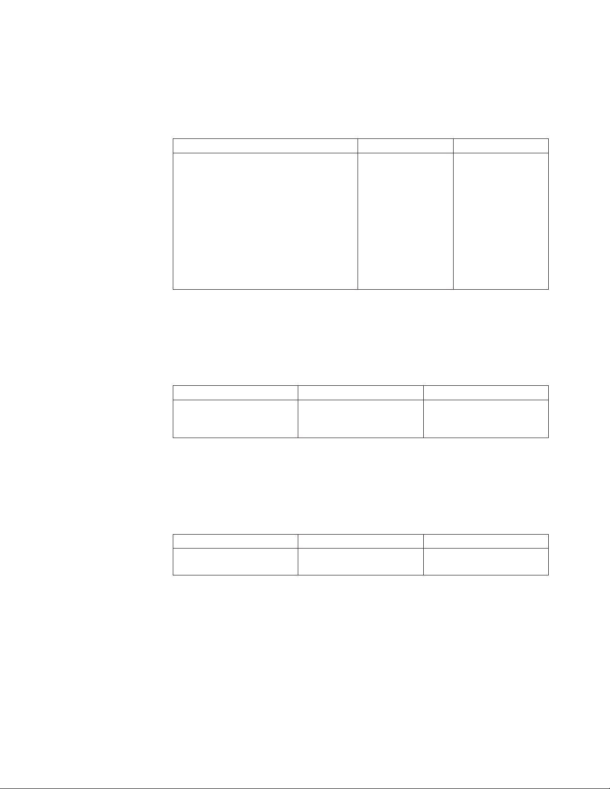
Display language
Table 8 lists the parameters available for the Display Language Category. Refer to
Chapter 11, “Display Language” for detailed information on setting these
parameters.
Table 8. Display Language
Parameters Values Default
Display Language 000 English
Vital Product Data
Table 9 lists the parameters available for the Vital Product Data Category. Refer to
Chapter 12, “Vital Product Data” for detailed information on setting these
parameters.
000 English
001 Deutsch
002 Français
003 Italiano
004 Español
005 Nederlands
006 Dansk
007 Português
008 Norsk
009 Svenska
010 Suomi
011 Polski
Table 9. Vital Product Data Category
Parameters Values Default
Serial Number
Device Specific Information
Quiet Print
Table 10 lists the parameters available for the Quiet Print category. Refer to
Chapter 13, “Quiet Print,” on page 129 for detailed information on setting these
parameters.
Table 10. Quiet Print Category
Parameters Values Default
Quiet Print No
xxxxxxx
xxxxxxxxxxxxxxxx
Ye s
0000000
0000000000000000
No
Chapter 3. Checking and changing configuration parameter values 47
Page 64

Hex Print
Table 11 lists the parameters available for the Hex Print category. Refer to
Chapter 14, “Hex Print,” on page 131 for detailed information on setting these
parameters.
Table 11. Hex Print Category
Parameters Values Default
Hex Print No
Quit From Menu
Table 12 lists the parameters available for the Quit From Menu Category. Refer to
Chapter 15, “Quit From Menu” for detailed information on setting these
parameters.
Table 12. Quit From Menu Category
Parameters Values Default
Quit From Menu Restore Previous Values N/A
No
Ye s
48 User’s Guide
Page 65

Chapter 4. Configuration storage
Custom sets ..............49
Non-custom set .............49
Save Current Values in Custom Sets ......50
Recall Custom Set values ..........51
This chapter describes the procedures for setting configuration storage values. It
explains the two types of configuration storage (custom and non-custom) and
describes how to create and save them in printer memory.
Custom sets
There are eight custom sets (A, B, C, D, E, F, G, and H) that you can create and
retain. Custom sets contain values for the parameters listed in Chapter 3,
“Checking and changing configuration parameter values,” on page 37:.
Non-custom set
The non-custom set contains parameter values that stay the same, no matter which
custom set you are using. The following parameter values are saved in this part of
printer memory:
v Configuration Storage
– All
v Attachment
v Parallel Interface
– Printer Compatibility 6 (Init)
– Interface Type
– Input Buffer Size
– Select-In Signal
– AutoFeed-XT
v Serial Interface
– All, except Interface Type, Input Buffer Size, Data Bits, Baud Rate, Parity,
Pacing Control, and Connection Type
v LAN Interface
– All
v Printer Setup
– Paper Source
v Power On Reset
–Yes
v Vital Product Data
v Quit From Menu
Power-On Custom Set ...........51
Power-On Paper Source ..........52
Recall factory defaults ...........53
Printing custom sets ...........54
Changes to these values are saved at the same time you save values that go into
custom sets. If you save a change made to one of these non-custom set parameter
values, the new value will be in effect no matter which custom set you recall.
49
Page 66

Save Current Values in Custom Sets
The Save Current Values stores the current values of the configuration parameters
to one of the eight custom sets (described in “Custom sets” on page 49).
You can save the current values to:
v Custom Set A
v Custom Set B
v Custom Set C
v Custom Set D
v Custom Set E
v Custom Set F
v Custom Set G
v Custom Set H
All of the custom sets are initially set to the manufacturing default values.
To save current configuration values in a custom set, follow these steps:
1. Press MENU.
2. Press SCROLL/MICRO
CONFIGURATION MENU
Configuration Storage
3. Press ENTER.
4. Press SCROLL/MICRO
or SCROLL/MICRO until the printer displays
or SCROLL/MICRO until the printer displays
Configuration Storage
Save Current Values
5. Press ENTER to display the current value.
6. Press SCROLL/MICRO or SCROLL/MICRO until the desired custom set
value is displayed.
Note: If you have previously created a custom set definition for that letter, that
information will be replaced with the new information when you press
ENTER.
7. Press ENTER.
The printer displays a message similar to
Save Current Values
Custom Set A Saved
8. Use START or RETURN to exit the Menu. See “Exiting the Configuration
Menu” on page 39. The display will be updated to show the new custom set
that is in use. See “Custom Set In-Use Indicator” on page 29.
50 User’s Guide
Page 67

Recall Custom Set values
The Recall Custom Set values recalls configuration parameters previously stored.
(Custom sets are described in “Custom sets” on page 49.)
You can recall current values from:
v Custom Set A
v Custom Set B
v Custom Set C
v Custom Set D
v Custom Set E
v Custom Set F
v Custom Set G
v Custom Set H
Note: When a new custom set is recalled, a partial reset is automatically
performed when exiting from the configuration menu if the value of at least
one of the parameters that requires a partial reset has been changed.
Buffered data will be lost.
To recall custom set values, follow these steps:
1. Press MENU.
2. Press SCROLL/MICRO
CONFIGURATION MENU
Configuration Storage
or SCROLL/MICRO until the printer displays
3. Press ENTER.
4. Press SCROLL/MICRO
Configuration Storage
Recall Custom Set Values
5. Press ENTER to display the current value.
6. Press SCROLL/MICRO
value is displayed.
7. Press ENTER. The printer displays a message similar to
Recall Custom Set
Custom Set A Recalled
8. Use START or RETURN to exit the Menu. See “Exiting the Configuration
Menu” on page 39.
Power-On Custom Set
The Power-On Custom Set is the custom set that is used when the printer is turned
on. The Last Used value means the custom set used before the printer was
powered off is to be used as the power-on custom set.
You can change the Power-On Custom Set to:
v Last Used (Default)
v Custom Set A
v Custom Set B
v Custom Set C
or SCROLL/MICRO until the printer displays
or SCROLL/MICRO until the desired custom set
Chapter 4. Configuration storage 51
Page 68

v Custom Set D
v Custom Set E
v Custom Set F
v Custom Set G
v Custom Set H
To change or check the power-on custom set, follow these steps:
1. Press MENU.
2. Press SCROLL/MICRO
CONFIGURATION MENU
Configuration Storage
or SCROLL/MICRO until the printer displays
3. Press ENTER.
4. Press SCROLL/MICRO or SCROLL/MICRO until the printer displays
Configuration Storage
Power-On Custom Set
5. Press ENTER to display the current value.
6. Press SCROLL/MICRO or SCROLL/MICRO until the desired custom set for
the new power-on custom set is displayed.
7. Press ENTER.
An asterisk (*) will be displayed in front of the selected custom set.
8. Use START or RETURN to exit the Menu. See “Exiting the Configuration
Menu” on page 39.
Power-On Paper Source
The Power-On Paper Source allows you to select which paper source is to be used
when the printer is turned on. The Last Used value means that the paper source
used before the printer was powered off is to be used as the power-on paper
source.
You can change the Power-On Paper Source to:
v Front (Default)
v Rear
v Last Used
Selecting Last Used causes the Paper Source parameter (in the Printer Setup menu)
to be updated whenever the data stream selects a paper source. If the data stream
attempts to select the operator panel setting for power-on paper source, the most
recently selected paper source will be used instead.
To change or check the power-on paper source, follow these steps:
1. Press MENU.
2. Press SCROLL/MICRO
CONFIGURATION MENU
Configuration Storage
3. Press ENTER.
4. Press SCROLL/MICRO or SCROLL/MICRO until the printer displays
or SCROLL/MICRO until the printer displays
52 User’s Guide
Page 69

Configuration Storage
Power-On Paper Source
5. Press ENTER to display the current value.
6. Press SCROLL/MICRO
Paper Source value is displayed.
7. Press ENTER.
An asterisk (*) will be displayed in front of the selected paper source.
8. Use START or RETURN to exit the Menu. See “Exiting the Configuration
Menu” on page 39.
Recall factory defaults
This function sets all parameter values to the original manufacturing default
values, except Vital Product Data and Printer Address (Twinax attachment). These
settings can only be changed through their own menu selection.
The printer is shipped with all of the custom sets set to manufacturing default
values and custom set A as the power-on custom set. The Recall Factory Defaults
function does not affect the values saved in custom sets.
Note: When factory defaults are recalled, a partial reset is automatically performed
when exiting from the configuration menu if the value of at least one of the
parameters that requires a partial reset has been changed. Buffered data will
be lost.
or SCROLL/MICRO until the desired Power-on
To recall the factory defaults, follow these steps:
1. Press MENU.
2. Press SCROLL/MICRO
CONFIGURATION MENU
Configuration Storage
or SCROLL/MICRO until the printer displays
3. Press ENTER.
4. Press SCROLL/MICRO
Configuration Storage
Recall Factory Defaults
or SCROLL/MICRO until the printer displays
5. Press ENTER.
The printer displays
Recall Factory Defaults
Yes
6. Press ENTER.
The printer displays
Recall Factory Defaults
Factory Defaults Recalled
7. Use START or RETURN to exit the Menu. See “Exiting the Configuration
Menu” on page 39.
Chapter 4. Configuration storage 53
Page 70

Printing custom sets
Use this function to create a printout of the eight custom set values.
On the first page of the printout, each custom set is identified as either In Use or
as Factory Defaults.
In Use At least one value in the custom set is different from the factory
Factory Defaults
If a custom set is identical to the factory defaults, it will be identified as Factory
Defaults. If the only change from factory defaults is a non-custom set parameter
value (a value that stays the same no matter which custom set you are using), only
the first custom set will be identified as In Use. The other custom sets will be
shown as factory defaults.
To print the custom sets:
1. Press STOP to make the printer not ready.
2. Press TEST.
3. Press SCROLL/MICRO
OPERATOR PRINT TESTS
Print Custom Sets
default value. A flag (****) is printed after each parameter value
that is different from the factory default.
A custom set that is identical to one of the factory defaults.
or SCROLL/MICRO until the printer displays
4. Use ENTER or START to begin the test. The printout will list all the custom
sets.
The Ready indicator is lighted, and the Print Test prints. The printout is
complete when the Ready indicator is no longer lighted.
5. Press Cancel Print to make the printer ready,orRETURN to make the printer
not ready.
54 User’s Guide
Page 71

Chapter 5. Attachment options
This chapter describes the procedures for setting your printer attachment. Your
printer is capable of attaching individually through the following attachment
interface options:
v Bidirectional IEEE 1284 Parallel
v Serial RS232/C 9-Pin
v USB 2.0
v ASCII Ethernet 10/100 BaseT LAN
v ASCII-IPDS Ethernet 10/100 BaseT LAN
The attachments you have depend on what you requested at the time you placed
your order for the printer. To change or check the attachment selection, follow
these steps:
1. Press MENU.
2. Press SCROLL/MICRO
displays
CONFIGURATION MENU
Attachment
3. Press ENTER.
The printer displays
or SCROLL/MICRO (down) until the printer
Attachment
* xxxxxx
Where xxxxxx (depending on your currently selected attachment) can be Hot
Port Switch, Parallel, Serial, USB, LAN ASCII, or LAN IPDS.
4. Press SCROLL/MICRO
displayed.
5. Press ENTER.
An asterisk (*) will be displayed in front of the selected value.
6. Press START or RETURN to exit the Menu. See “Exiting the Configuration
Menu” on page 39.
or SCROLL/MICRO until the desired value is
55
Page 72

56 User’s Guide
Page 73

Chapter 6. IPDS Configuration
Characters Per Inch (CPI)..........57
Lines Per Inch (LPI) ...........58
Maximum Print Position (MPP)........58
Maximum Page Length (MPL) ........59
Print Quality ..............60
Print language .............61
This section describes how to check and change IPDS configuration parameters for
your 4247 printer. The chapter is divided into sections according to parameter.
Refer to this partial table of contents for parameter and page listings.
Characters Per Inch (CPI)
You can set the Characters Per Inch (CPI) to any of the following values:
v 10 (Default)
v 12
v 15
v 16.7
Notes:
1. It is possible to specify a CPI value that causes the page width (maximum print
position) to exceed the maximum physical page width. If this occurs, the
printer automatically changes the maximum print position to the highest valid
value for the new CPI setting. See “Maximum Print Position (MPP)” on page 58
for more information.
2. This parameter can be overridden by the computer.
3. Only 10 CPI is valid when either OCR-A or OCR-B is selected as a print
language.
Emulation mode .............62
Media Size Priority ............63
Bar Code Mode .............64
Graphics Mode .............65
Alarm control .............66
To change or check the CPI value, follow these steps:
1. Press MENU.
2. Press SCROLL/MICRO
CONFIGURATION MENU
IPDS Configuration
or SCROLL/MICRO until the printer displays
3. Press ENTER.
The printer displays
IPDS Configuration
Characters Per Inch
4. Press ENTER to display the current value.
5. Press SCROLL/MICRO
or SCROLL/MICRO until the desired value for CPI
is displayed.
6. Press ENTER.
An asterisk (*) will be displayed in front of the selected value.
7. Press START or RETURN to exit the Menu. See “Exiting the Configuration
Menu” on page 39.
57
Page 74

Lines Per Inch (LPI)
You can set the lines per inch (LPI) for the printer to either of the following values:
v 6 (Default)
v 8
Note: This parameter can be overridden by the computer.
To change or check the LPI, follow these steps:
1. Press MENU.
2. Press SCROLL/MICRO
CONFIGURATION MENU
IPDS Configuration
3. Press ENTER.
4. Press SCROLL/MICRO
IPDS Configuration
Lines Per Inch
5. Press ENTER to display the current value.
6. Press SCROLL/MICRO or SCROLL/MICRO until the desired value for LPI
is displayed.
7. Press ENTER.
An asterisk (*) will be displayed in front of the selected value.
8. Press START or RETURN to exit the Menu. See “Exiting the Configuration
Menu” on page 39.
or SCROLL/MICRO until the printer displays
or SCROLL/MICRO until the printer displays
Maximum Print Position (MPP)
The maximum print position (MPP) equals the number of characters the printer
prints on a line. The default value is 132.
The CPI setting you choose directly influences the MPP value you select. The MPP
and CPI settings determine the length of the print line. The maximum line length
for the printer is 345.44 mm (13.6 in.).
The CPI setting and the line length determine the MPP. Multiply the CPI by the
line length to determine the appropriate MPP:
MPP = CPI x line length (in inches)
If your CPI is: MPP cannot be greater than:
10 136
12 163
15 204
16.7 227
Notes:
1. Setting the MPP larger than the paper width can result in lost data because of
printing on the platen and may damage the platen and the printhead.
2. This parameter can be overridden by the computer.
58 User’s Guide
Page 75

To change or check the MPP value, follow these steps:
1. Press MENU.
2. Press SCROLL/MICRO
CONFIGURATION MENU
IPDS Configuration
3. Press ENTER.
4. Press SCROLL/MICRO
IPDS Configuration
Maximum Print Position
5. Press ENTER to display the current value.
6. Press SCROLL/MICRO
MPP is displayed.
7. Press ENTER.
An asterisk (*) will be displayed in front of the selected value.
8. Press START or RETURN to exit the Menu. See “Exiting the Configuration
Menu” on page 39.
Maximum Page Length (MPL)
or SCROLL/MICRO until the printer displays
or SCROLL/MICRO until the printer displays
or SCROLL/MICRO until the desired value for
You can set the maximum page length (MPL) for the printer from 1–660 lines for 6
LPI and 1–880 lines for 8 LPI. The default value is 66 lines.
MPL equals the number of print lines the printer can print on a page. MPL is the
page length stated in number of print lines.
See the following example to determine how to calculate the MPL.
The LPI and the page length determine the MPL. Multiply the lines per inch by the
page length to determine the appropriate MPL:
MPL = LPI x page length (in inches)
For example, if LPI=6 and page length=254 mm (10 in.), then
MPL=6x10
MPL = 60
254 mm
(10 in.)
C7QU5095
Note: This parameter can be overridden by the computer.
To change or check the MPL, follow these steps:
Chapter 6. IPDS Configuration 59
Page 76

Print Quality
1. Press MENU.
2. Press SCROLL/MICRO
CONFIGURATION MENU
IPDS Configuration
or SCROLL/MICRO until the printer displays
3. Press ENTER.
4. Press SCROLL/MICRO or SCROLL/MICRO until the printer displays
IPDS Configuration
Maximum Page Length
5. Press ENTER to display the current value.
6. Press SCROLL/MICRO
or SCROLL/MICRO until the desired value for
MPL is displayed.
7. Press ENTER.
An asterisk (*) will be displayed in front of the selected value.
8. Press START or RETURN to exit the Menu. See “Exiting the Configuration
Menu” on page 39.
You can set the Print Quality for the printer to any of the following values:
v DP (Data Processing) Quality (Default)
v DP Text Quality
v Near Letter Quality (NLQ).
Notes:
1. This parameter can be overridden by the computer.
2. Only Near Letter Quality is valid when either OCR-A or OCR-B is selected as
the print language.
To change or check the Print Quality, follow these steps:
1. Press MENU.
2. Press SCROLL/MICRO
CONFIGURATION MENU
IPDS Configuration
or SCROLL/MICRO until the printer displays
3. Press ENTER.
4. Press SCROLL/MICRO
IPDS Configuration
Print Quality
or SCROLL/MICRO until the printer displays
5. Press ENTER to display the current value.
6. Press SCROLL/MICRO or SCROLL/MICRO until the desired value for
Print Quality is displayed.
7. Press ENTER.
An asterisk (*) will be displayed in front of the selected value.
8. Press START or RETURN to exit the Menu. See “Exiting the Configuration
Menu” on page 39.
60 User’s Guide
Page 77

Print language
The following print languages are available on the printer when attachment is set
to LAN IPDS. The default is marked with an asterisk (*). You can select any print
language that is available for your printer.
Determine the value for the language setting you want from the following table:
Table 13. Supported Print Languages
Code Page Language
37 USA/Canada
260 Canadian French
273 Austrian/German
274 Belgian Old
275 Brazilian
277 Danish/Norwegian
278 Finnish/Swedish
280 Italian
281 Japanese English
282 Portuguese
284 Spanish/Spanish Speaking
285 English (UK)
290 Japanese Katakana
297 French/French Azerty
420 Arabic
423 Greek (Old)
424 Hebrew Bulletin
500 (*) International 5/Swiss/Belgian
813 Greek/Latin (ISO 8859-7) + euro
833 Korean
838 Thai
870 Latin 2/ROECE
871 Icelandic
875 Greek (New) + euro
880 Cyrillic
890 Yugoslav (Old)
892 OCR-A
893 OCR-B
924 Latin 9 (ISO 8859) + euro
1025 Cyrillic Multilingual
1026 Latin-5 Turkey
1097 Farsi
1112 Baltic Multilingual
1122 Estonian
Chapter 6. IPDS Configuration 61
Page 78

Table 13. Supported Print Languages (continued)
Code Page Language
1140 USA/Canada + euro
1141 Austrian/German + euro
1142 Danish/Norwegian + euro
1143 Finnish/Swedish + euro
1144 Italian + euro
1145 Spanish/Spanish Speaking + euro
1146 English (UK) + euro
1147 French + euro
1148 International 5/Belgian New + euro
1149 Icelandic + euro
Notes:
1. The printer performs a partial reset to put any change to this parameter value
into effect when you exit the Configuration Menu with START or RETURN.
Buffered data will be lost.
2. This parameter can be overridden by the computer.
3. When either OCR-A or OCR-B is selected, the selectable options for CPI and
print quality become fixed at 10 CPI and Near Letter Quality, respectively.
Emulation mode
To change or check the print language value, follow these steps:
1. Press MENU.
2. Press SCROLL/MICRO
CONFIGURATION MENU
IPDS Configuration
or SCROLL/MICRO until the printer displays
3. Press ENTER.
4. Press SCROLL/MICRO
IPDS Configuration
Print Language
or SCROLL/MICRO until the printer displays
5. Press ENTER to display the current value.
6. Press SCROLL/MICRO
or SCROLL/MICRO until the desired language
value is displayed.
7. Press ENTER.
An asterisk (*) will be displayed in front of the selected value.
8. Press START or RETURN to exit the Menu. See “Exiting the Configuration
Menu” on page 39.
62 User’s Guide
You can set Emulation Mode to the following values:
v 4247 (Default)
v 4224
v 4230
Page 79

Notes:
1. The printer performs a partial reset to put any change to this parameter value
into effect when you exit the Configuration Menu with START or RETURN.
Buffered data will be lost.
2. When changing the value of the Emulation Mode, verify the Data Stream and
the Printer Address you have set.
To change or check the emulation mode, follow these steps:
1. Press MENU.
2. Press SCROLL/MICRO
CONFIGURATION MENU
IPDS Configuration
or SCROLL/MICRO until the printer displays
3. Press ENTER.
4. Press SCROLL/MICRO or SCROLL/MICRO until the printer displays
IPDS Configuration
Emulation Mode
5. Press ENTER to display the current value.
6. Press SCROLL/MICRO
or SCROLL/MICRO until the desired value for
Emulation Mode is displayed.
7. Press ENTER.
An asterisk (*) will be displayed in front of the selected value.
8. Press START or RETURN to exit the Menu. See “Exiting the Configuration
Menu” on page 39.
Media Size Priority
This parameter is available only if the IPDS feature is installed, and the IPDS data
stream is selected. It affects the use of the XOH Set Media Size (SMS) order. This
order may be used in the IPDS data stream to set the page size. The Media Size
Priority setting specifies whether XOH-SMS orders take precedence over the
operator panel settings for maximum print position (MPP) and maximum page
length (MPL).
The following values will be displayed in the menu:
Standard The smaller page size values have priority. The page size will be the
Alternate
(default)
The media size is defined by the MPP and MPL parameters.
To change or check the Media Size Priority, follow these steps:
1. Press MENU.
2. Press SCROLL/MICRO
intersection (smaller values) of the operator panel settings and the XOH-SMS
X and Y values.
The XOH-SMS order values have priority. If an XOH-SMS order is present,
its values will be used to define the page size instead of the operator panel
settings.
or SCROLL/MICRO until the printer displays
Chapter 6. IPDS Configuration 63
Page 80
Bar Code Mode
CONFIGURATION MENU
IPDS Configuration
3. Press ENTER.
4. Press SCROLL/MICRO
IPDS Configuration
Media Size Priority
or SCROLL/MICRO until the printer displays
5. Press ENTER to display the current value.
6. Press SCROLL/MICRO or SCROLL/MICRO until the desired value for
media size priority is displayed.
7. Press ENTER.
An asterisk (*) will be displayed in front of the selected value.
8. Press START or RETURN to exit the Menu. See “Exiting the Configuration
Menu” on page 39.
This parameter is valid only if the IPDS feature is installed and the IPDS data
stream is selected. Changing the value of this parameter can affect throughput in
some printing environments.
You can set the Bar Code Mode to any of the following values:
High
(Default)
Low Low Contrast Bar Codes
Computer
Selected
High Contrast Bar Codes
Contrast as specified by the IPDS data stream
Note: The printer performs a partial reset to put any change to this parameter
value into effect when you exit the Configuration Menu with START or
RETURN. Buffered data will be lost.
To change or check the bar code mode, follow these steps:
1. Press MENU.
2. Press SCROLL/MICRO
CONFIGURATION MENU
IPDS Configuration
or SCROLL/MICRO until the printer displays
3. Press ENTER.
4. Press SCROLL/MICRO
IPDS Configuration
Bar Code Mode
or SCROLL/MICRO until the printer displays
5. Press ENTER to display the current value.
6. Press SCROLL/MICRO
or SCROLL/MICRO until the desired value for bar
code mode is displayed
7. Press ENTER.
An asterisk (*) will be displayed in front of the selected value.
64 User’s Guide
Page 81

Graphics Mode
8. Press START or RETURN to exit the Menu. See “Exiting the Configuration
Menu” on page 39.
This parameter is available only if the IPDS feature is installed and the IPDS data
stream is selected. Changing the value of this parameter can affect throughput in
some printing environments.
You can set the Graphics Mode to any of the following values:
High
(Default)
Low Low Density Graphics
Computer
Selected
High Density Graphics
Density as specified by the IPDS data stream
Note: The printer performs a partial reset to put any change to this parameter
value into effect when you exit the Configuration Menu with START or
RETURN. Buffered data will be lost.
To change or check the graphics mode, follow these steps:
1. Press MENU.
2. Press SCROLL/MICRO
CONFIGURATION MENU
IPDS Configuration
or SCROLL/MICRO until the printer displays
3. Press ENTER.
4. Press SCROLL/MICRO
IPDS Configuration
Graphics Mode
or SCROLL/MICRO until the printer displays
5. Press ENTER to display the current value.
6. Press SCROLL/MICRO
or SCROLL/MICRO until the desired value for
graphics mode is displayed.
7. Press ENTER.
An asterisk (*) will be displayed in front of the selected value.
8. Press START or RETURN to exit the Menu. See “Exiting the Configuration
Menu” on page 39.
Chapter 6. IPDS Configuration 65
Page 82
Alarm control
You can set the audible printer alarm to either of the following values:
v Enabled (Default)
v Disabled
Note: Pressing SET TOP OF FORM and some unit check conditions sound the
alarm, even if it is disabled.
To change or check the alarm control, follow these steps:
1. Press MENU.
2. Press SCROLL/MICRO
CONFIGURATION MENU
IPDS Configuration
3. Press ENTER.
4. Press SCROLL/MICRO
IPDS Configuration
Alarm Control
5. Press ENTER to display the current value.
6. Press SCROLL/MICRO
alarm control is displayed.
7. Press ENTER.
An asterisk (*) will be displayed in front of the selected value.
8. Press START or RETURN to exit the Menu. See “Exiting the Configuration
Menu” on page 39.
or SCROLL/MICRO until the printer displays
or SCROLL/MICRO until the printer displays
or SCROLL/MICRO until the desired value for
66 User’s Guide
Page 83

Chapter 7. ASCII Configuration
Characters Per Inch (CPI)..........67
Lines Per Inch (LPI) ...........68
Maximum Print Position (MPP)........69
Maximum Page Length (MPL) ........70
Perforation skipping ...........71
Emulation Mode.............71
Print language .............72
Print quality ..............74
NLQ typeface .............75
Character set ..............75
Printer Compatibility 3 (automatic line feed on
carriage return) .............76
Printer Compatibility 4 (automatic carriage return
on line feed) ..............76
Printer Compatibility 5 (form feed suppression) . . 77
Printer Compatibility 6 (Init) ........78
Printer Compatibility 7 (condensed print) ....79
Printer Compatibility 8 (slashed zero) .....79
Printer Compatibility 9 (20 CPI) .......80
Alarm control .............81
Override Host parameters .........82
Paper source .............82
Characters Per Inch (CPI).........83
Lines Per Inch (LPI) ..........84
Maximum Page Length .........85
This chapter describes the procedures for checking and changing ASCII
configuration parameters for your 4247 printer. The chapter is divided into sections
according to parameter. Refer to the partial table of contents at the beginning of
this chapter for parameter and page listings.
Parallel interface .............86
Interface type .............86
Input Buffer Size ...........86
Select-In ..............87
AutoFeed-XT .............88
Serial interface .............88
Interface type .............88
Input Buffer Size ...........89
Data Bits ..............90
Baud Rate ..............90
Parity ...............91
Pacing Control ............92
Connection Type............92
LAN Interface .............93
IP Address Assignment .........93
IP Address .............93
Subnet Mask .............94
Default Gateway ...........95
Host Name .............95
Workgroup Name ...........96
SMTP Service .............97
Mail Server Address ..........97
E-Mail Address (Receiver) ........98
E-Mail Address (Sender) .........99
Characters Per Inch (CPI)
You can set the Characters Per Inch (CPI) to any of the following values:
v 10 (Default)
v 12
v 15
v 16.7
v 17.1
v 20
Notes:
1. It is possible to specify a CPI value that causes the page width (maximum print
position) to exceed the maximum physical page width. If this occurs, the
printer automatically changes the maximum print position to the highest valid
value for the new CPI setting. See “Maximum Print Position (MPP)” on page 69
for more information.
2. This parameter can be overridden by the computer.
3. Only 10 CPI is valid when either OCR-A or OCR-B is selected as a print
language.
67
Page 84

To change or check the CPI value, follow these steps:
1. Press MENU.
2. Press SCROLL/MICRO
CONFIGURATION MENU
ASCII Configuration
3. Press ENTER.
The printer displays
ASCII Configuration
Characters Per Inch
4. Press ENTER to display the current value.
5. Press SCROLL/MICRO
is displayed.
6. Press ENTER.
An asterisk (*) will be displayed in front of the selected value.
7. Press START or RETURN to exit the Menu. See “Exiting the Configuration
Menu” on page 39.
Lines Per Inch (LPI)
or SCROLL/MICRO until the printer displays
or SCROLL/MICRO until the desired value for CPI
You can set the lines per inch (LPI) for the printer to either of the following values:
v 6 (Default)
v 8
Note: This parameter can be overridden by the computer.
To change or check the LPI, follow these steps:
1. Press MENU.
2. Press SCROLL/MICRO
CONFIGURATION MENU
ASCII Configuration
or SCROLL/MICRO until the printer displays
3. Press ENTER.
4. Press SCROLL/MICRO or SCROLL/MICRO until the printer displays
ASCII Configuration
Lines Per Inch
5. Press ENTER to display the current value.
6. Press SCROLL/MICRO
or SCROLL/MICRO until the desired value for LPI
is displayed.
7. Press ENTER.
An asterisk (*) will be displayed in front of the selected value.
8. Press START or RETURN to exit the Menu. See “Exiting the Configuration
Menu” on page 39.
68 User’s Guide
Page 85

Maximum Print Position (MPP)
The maximum print position (MPP) equals the number of characters the printer
prints on a line. The default value is 136.
The CPI setting you choose directly influences the MPP value you select. The MPP
and CPI settings determine the length of the print line. The maximum line length
for the printer is 345.44 mm (13.6 in.).
The CPI setting and the line length determine the MPP. Multiply the CPI by the
line length to determine the appropriate MPP:
MPP = CPI x line length (in inches)
If your CPI is: MPP cannot be greater than:
10 136
12 163
15 204
16.7 227
17.1 233
20 272
Notes:
1. Setting the MPP larger than the paper width can result in lost data because of
printing on the platen and may damage the platen and the printhead.
2. This parameter can be overridden by the computer.
To change or check the MPP value, follow these steps:
1. Press MENU.
2. Press SCROLL/MICRO
CONFIGURATION MENU
ASCII Configuration
or SCROLL/MICRO until the printer displays
3. Press ENTER.
4. Press SCROLL/MICRO or SCROLL/MICRO until the printer displays
ASCII Configuration
Maximum Print Position
5. Press ENTER to display the current value.
6. Press SCROLL/MICRO
or SCROLL/MICRO until the desired value for
MPP is displayed.
7. Press ENTER.
An asterisk (*) will be displayed in front of the selected value.
8. Press START or RETURN to exit the Menu. See “Exiting the Configuration
Menu” on page 39.
Chapter 7. ASCII Configuration 69
Page 86

Maximum Page Length (MPL)
You can set the maximum page length (MPL) for the printer from 1–880 lines,
depending on the LPI setting. The default value is 66 lines.
MPL equals the number of print lines the printer can print on a page. MPL is the
page length stated in number of print lines.
See the following example to determine how to calculate the MPL.
The LPI and the page length determine the MPL. Multiply the lines per inch by the
page length to determine the appropriate MPL:
MPL = LPI x page length (in inches)
For example, if LPI=6 and page length=254 mm (10 in.), then
MPL=6x10
MPL = 60
254 mm
(10 in.)
C7QU5095
Note: This parameter can be overridden by the computer.
To change or check the MPL, follow these steps:
1. Press MENU.
2. Press SCROLL/MICRO
CONFIGURATION MENU
ASCII Configuration
or SCROLL/MICRO until the printer displays
3. Press ENTER.
4. Press SCROLL/MICRO
ASCII Configuration
Maximum Page Length
or SCROLL/MICRO until the printer displays
5. Press ENTER to display the current value.
6. Press SCROLL/MICRO
or SCROLL/MICRO until the desired value for
MPL is displayed.
7. Press ENTER.
An asterisk (*) will be displayed in front of the selected value.
8. Press START or RETURN to exit the Menu. See “Exiting the Configuration
Menu” on page 39.
70 User’s Guide
Page 87

Perforation skipping
Use this parameter to create a bottom margin on your printed page, if the host
data stream does not create a bottom margin.
The range of values is 0 to 879 lines, at 8 lpi. The default value is 0.
To change of check perforation skipping, follow these steps:
1. Press MENU.
2. Press SCROLL/MICRO
CONFIGURATION MENU
ASCII Configuration
3. Press ENTER.
4. Press SCROLL/MICRO
ASCII Configuration
Perforation Skipping
5. Press ENTER to display the current value.
6. Press SCROLL/MICRO
Skipping value is displayed.
7. Press ENTER.
An asterisk (*) will be displayed in front of the selected value.
8. Press START or RETURN to exit the Menu. See “Exiting the Configuration
Menu” on page 39.
or SCROLL/MICRO . The printer displays
or SCROLL/MICRO . The printer displays
or SCROLL/MICRO until the desired Perforation
Emulation Mode
You can set Emulation Mode to the following values:
v 4247 (Default)
v 2381 Personal Printer
v 4202 Proprinter III XL
v Epson-FX
Note: The printer performs a partial reset to put any change to this parameter
value into effect when you exit the Configuration Menu with START or
RETURN. Buffered data will be lost.
To change or check the emulation mode, follow these steps:
1. Press MENU.
2. Press SCROLL/MICRO
CONFIGURATION MENU
ASCII Configuration
or SCROLL/MICRO until the printer displays
3. Press ENTER.
4. Press SCROLL/MICRO
ASCII Configuration
Emulation Mode
or SCROLL/MICRO until the printer displays
5. Press ENTER to display the current value.
6. Press SCROLL/MICRO
or SCROLL/MICRO until the desired value for
Emulation Mode is displayed.
Chapter 7. ASCII Configuration 71
Page 88

Print language
7. Press ENTER.
An asterisk (*) will be displayed in front of the selected value.
8. Press START or RETURN to exit the Menu. See “Exiting the Configuration
Menu” on page 39.
The following print languages are available on the printer when attachment is set
to Parallel, Serial, USB, or LAN ASCII. The defaults are marked with an asterisk
(*). You can select any print language that is available for your printer.
Determine the value for the language setting you want from the following tables:
Code Page (When emulation
Code Page (When emulation
is set to Epson-FX)
0(*) N/A USA
1 N/A France
2 N/A Germany
3 N/A U.K.
4 N/A Denmark I
5 N/A Sweden
6 N/A Italy
7 N/A Spain I
8 N/A Japan
9 N/A Norway
10 N/A Denmark II
11 N/A Spain II
12 N/A Latin America I
13 N/A French Canadian
14 N/A Latin American II
N/A 437(*) USA PC A-54
N/A 737 Greek (MS DOS)
N/A 813 Greek/Latin (ISO 8859-7)
N/A 819 Latin 1 (ISO 8859-1)
N/A 850 PC Multilingual
N/A 851 Greek (Old)
N/A 852 Latin 2/ROECE
N/A 853 Latin 3 PC
N/A 855 Cyrillic PC
N/A 857 Latin 5 Turkey + euro
N/A 858 euro PC Multilingual + euro
N/A 860 Portuguese
N/A 861 Icelandic
N/A 862 Hebrew
is set to 4247, 4202 III XL,
2381 Personal Printer) Language
72 User’s Guide
Page 89

Code Page (When emulation
Code Page (When emulation
is set to Epson-FX)
N/A 863 Canadian French
N/A 864 Arabic
N/A 865 Danish/Norwegian
N/A 866 PC Data, Cyrillic, Russian
N/A 869 Greek (New) + euro
N/A 874 Thai
N/A 876 OCR-A
N/A 877 OCR-B
N/A 912 Latin 2 (ISO 8859-2)
N/A 913 Latin 3 (ISO 8859-3)
N/A 914 Latin 4 (ISO 8859-4)
N/A 915 Cyrillic (ISO 8859-5)
N/A 916 Latin 8 (ISO 8859-8)
N/A 920 Latin 5 (ISO 8859-9)
N/A 921 Baltic Multilingual
N/A 922 Estonian
N/A 923 Latin 9 (ISO8859-15)
N/A 1006 Urdu
N/A 1046 Arabic Extended
N/A 1089 Latin 6 (ISO 8859-6)
N/A 1098 Farsi PC
N/A 1116 Estonia PC
N/A 1117 Latvia PC
N/A 1118 Lithuania PC
N/A 1250 Central Europe Latin 2
N/A 1251 Cyrillic Windows + euro
is set to 4247, 4202 III XL,
2381 Personal Printer) Language
Notes:
1. The printer performs a partial reset to put any change to this parameter value
into effect when you exit the Configuration Menu with START or RETURN.
Buffered data will be lost.
2. This parameter can be overridden by the computer.
3. When either OCR-A or OCR-B is selected, the selectable options for CPI and
print quality become fixed at 10 CPI and Near Letter Quality, respectively.
To change or check the print language value, follow these steps:
1. Press MENU.
2. Press SCROLL/MICRO
CONFIGURATION MENU
ASCII Configuration
or SCROLL/MICRO until the printer displays
3. Press ENTER.
Chapter 7. ASCII Configuration 73
Page 90
Print quality
4. Press SCROLL/MICRO or SCROLL/MICRO until the printer displays
ASCII Configuration
Print Language
5. Press ENTER to display the current value.
6. Press SCROLL/MICRO
or SCROLL/MICRO until the desired language
value is displayed.
7. Press ENTER.
An asterisk (*) will be displayed in front of the selected value.
8. Press START or RETURN to exit the Menu. See “Exiting the Configuration
Menu” on page 39.
When emulation mode is set to 4247, 4202 III XL, or 2381 Personal Printer, you can
set the printer to any of the following values:
v DP (Data Processing) Quality (Default)
v DP Text Quality
v Near Letter Quality
v OCR-A
v OCR-B
When emulation mode is set to Epson-FX, you can set the printer to any of the
following values:
v DP Quality (Default)
v Courier
v Gothic
v OCR-A
v OCR-B
Notes:
1. This parameter can be overridden by the computer.
2. Only OCR-A and OCR-B are valid when either OCR-A or OCR-B is selected as
the print language.
To change or check the Print Quality, follow these steps:
1. Press MENU.
2. Press SCROLL/MICRO
CONFIGURATION MENU
ASCII Configuration
or SCROLL/MICRO until the printer displays
3. Press ENTER.
4. Press SCROLL/MICRO
ASCII Configuration
Print Quality
or SCROLL/MICRO until the printer displays
5. Press ENTER to display the current value.
6. Press SCROLL/MICRO or SCROLL/MICRO until the desired value for
Print Quality is displayed.
7. Press ENTER.
An asterisk (*) will be displayed in front of the selected value.
74 User’s Guide
Page 91

NLQ typeface
8. Press START or RETURN to exit the Menu. See “Exiting the Configuration
Menu” on page 39.
This parameter is displayed when emulation mode is set to 4247, 4202 III XL, or
2381 Personal Printer. This parameter allows you to set the font to be used for
Near Letter Quality printing. The following values are:
v Courier (Default)
v Gothic
To change or check the NLQ Typeface, follow these steps:
1. Press MENU.
2. Press SCROLL/MICRO
CONFIGURATION MENU
ASCII Configuration
or SCROLL/MICRO until the printer displays
3. Press ENTER.
4. Press SCROLL/MICRO or SCROLL/MICRO until the printer displays
CONFIGURATION MENU
NLQ Typeface
Character set
5. Press ENTER to display the current value.
6. Press SCROLL/MICRO
or SCROLL/MICRO until the desired value for
NLQ Typeface is displayed.
7. Press ENTER.
An asterisk (*) will be displayed in front of the selected value.
8. Press START or RETURN to exit the Menu. See “Exiting the Configuration
Menu” on page 39.
You can set the character set to any of the following values:
v PC1 (PC Character Set 1) (Default)
v PC2 (PC Character Set 2)
v Italic (Epson-FX only)
To change or check the Character Set, follow these steps:
1. Press MENU.
2. Press SCROLL/MICRO
CONFIGURATION MENU
ASCII Configuration
or SCROLL/MICRO until the printer displays
3. Press ENTER.
4. Press SCROLL/MICRO or SCROLL/MICRO until the printer displays
ASCII Configuration
Character Set
5. Press ENTER to display the current value.
Chapter 7. ASCII Configuration 75
Page 92

6. Press SCROLL/MICRO or SCROLL/MICRO until the desired value for
Character Set is displayed.
7. Press ENTER.
An asterisk (*) will be displayed in front of the selected value.
8. Press START or RETURN to exit the Menu. See “Exiting the Configuration
Menu” on page 39.
Printer Compatibility 3 (automatic line feed on carriage return)
You can set the printer to perform an automatic line feed on carriage return. You
can set this value to:
Disabled
(Default)
Enabled An automatic line feed is performed after a carriage return.
No line feed is performed after a carriage return.
To change or check the automatic line feed on carriage return setting, follow these
steps:
1. Press MENU.
2. Press SCROLL/MICRO
CONFIGURATION MENU
ASCII Configuration
or SCROLL/MICRO until the printer displays
3. Press ENTER.
4. Press SCROLL/MICRO
ASCII Configuration
Printer Compatibility
or SCROLL/MICRO until the printer displays
5. Press ENTER.
6. Press SCROLL/MICRO
Printer Compatibility
3 (Auto LF on CR)
or SCROLL/MICRO until the printer displays
7. Press ENTER to display the current value.
8. Press SCROLL/MICRO
or SCROLL/MICRO until the desired value for
Automatic Line Feed on Carriage Return is displayed.
9. Press ENTER.
An asterisk (*) will be displayed in front of the selected value.
10. Press START or RETURN to exit the Menu. See “Exiting the Configuration
Menu” on page 39.
Printer Compatibility 4 (automatic carriage return on line feed)
This parameter is displayed when emulation mode is set to 4247, 4202 III XL, or
2381 Personal Printer.
You can set the printer to perform an automatic carriage return on a line feed. You
can set this value to:
76 User’s Guide
Page 93

Disabled
(Default)
Enabled An automatic carriage return is performed after a line feed.
No automatic carriage return is performed after a line feed.
Note: If Emulation Mode is set to Epson-FX, an automatic carriage return is
performed after a line feed regardless of the setting.
To change or check the automatic carriage return after a line feed setting, follow
these steps:
1. Press MENU.
2. Press SCROLL/MICRO
CONFIGURATION MENU
ASCII Configuration
or SCROLL/MICRO until the printer displays
3. Press ENTER.
4. Press SCROLL/MICRO
ASCII Configuration
Printer Compatibility
or SCROLL/MICRO until the printer displays
5. Press ENTER.
6. Press SCROLL/MICRO
or SCROLL/MICRO until the printer displays
Printer Compatibility
4 (Auto CR on LF)
7. Press ENTER to display the current value.
8. Press SCROLL/MICRO or SCROLL/MICRO until the desired value for
Automatic Carriage Return on Line Feed is displayed.
9. Press ENTER.
An asterisk (*) will be displayed in front of the selected value.
10. Press START or RETURN to exit the Menu. See “Exiting the Configuration
Menu” on page 39.
Printer Compatibility 5 (form feed suppression)
This parameter is displayed when emulation mode is set to 4247, 4202 III XL, or
2381 Personal Printer.
You can set the printer to suppress host form feed commands or to honor all host
form feeds. You can set this value to:
Disabled
(Default)
Enabled Form feed commands from the host are ignored if the printer is at top of
All form feed commands from the host are honored.
form and no data for the page was received.
Note: Operator panel form feeds are not affected.
To change or check form feed suppression, follow these steps:
1. Press MENU.
2. Press SCROLL/MICRO
or SCROLL/MICRO until the printer displays
Chapter 7. ASCII Configuration 77
Page 94

CONFIGURATION MENU
ASCII Configuration
3. Press ENTER.
4. Press SCROLL/MICRO
ASCII Configuration
Printer Compatibility
or SCROLL/MICRO until the printer displays
5. Press ENTER.
6. Press SCROLL/MICRO or SCROLL/MICRO until the printer displays
Printer Compatibility
5 (FF Suppression)
7. Press ENTER to display the current value.
8. Press SCROLL/MICRO
or SCROLL/MICRO until the desired value for
Form Feed Suppression is displayed.
9. Press ENTER.
An asterisk (*) will be displayed in front of the selected value.
10. Press START or RETURN to exit the Menu. See “Exiting the Configuration
Menu” on page 39.
Printer Compatibility 6 (Init)
You can set the printer to detect the Init signal and perform a partial reset when
active or to ignore the signal. You can set this value to:
Disabled Init signal detection disabled. No action occurs when Init is activated.
Enabled
(Default)
To change or check the Init signal, follow these steps:
1. Press MENU.
2. Press SCROLL/MICRO
CONFIGURATION MENU
ASCII Configuration
3. Press ENTER.
4. Press SCROLL/MICRO
ASCII Configuration
Printer Compatibility
5. Press ENTER.
6. Press SCROLL/MICRO
Init signal detection enabled. When Init is activated, the printer performs a
partial reset.
or SCROLL/MICRO until the printer displays
or SCROLL/MICRO until the printer displays
or SCROLL/MICRO until the printer displays
78 User’s Guide
Printer Compatibility
6 (Init)
7. Press ENTER to display the current value.
8. Press SCROLL/MICRO
or SCROLL/MICRO until the desired value for
Init is displayed.
Page 95

9. Press ENTER.
An asterisk (*) will be displayed in front of the selected value.
10. Press START or RETURN to exit the Menu. See “Exiting the Configuration
Menu” on page 39.
Printer Compatibility 7 (condensed print)
This parameter is displayed when emulation mode is set to 4247, 4202 III XL, or
2381 Personal Printer.
You can set the printer CPI value for condensed print when a Shift In control is
received from the data stream. For more information, see the 4247 Model X03
Printer Programmer Manual.
You can set this value to:
v 15
v 16.7
v 17.1 (Default)
To change or check condensed print, follow these steps:
1. Press MENU.
2. Press SCROLL/MICRO
CONFIGURATION MENU
ASCII Configuration
or SCROLL/MICRO until the printer displays
3. Press ENTER.
4. Press SCROLL/MICRO
ASCII Configuration
Printer Compatibility
or SCROLL/MICRO until the printer displays
5. Press ENTER.
6. Press SCROLL/MICRO
Printer Compatibility
7 (Condensed Print)
or SCROLL/MICRO until the printer displays
7. Press ENTER to display the current value.
8. Press SCROLL/MICRO
or SCROLL/MICRO until the desired value for
Condensed Print is displayed.
9. Press ENTER.
An asterisk (*) will be displayed in front of the selected value.
10. Press START or RETURN to exit the Menu. See “Exiting the Configuration
Menu” on page 39.
Printer Compatibility 8 (slashed zero)
You can set this value to:
Disabled
(Default)
Enabled All printed zeros will appear with a slash.
All printed zeros will appear without a slash.
Chapter 7. ASCII Configuration 79
Page 96

To change or check the slashed zero, follow these steps:
1. Press MENU.
2. Press SCROLL/MICRO
CONFIGURATION MENU
ASCII Configuration
or SCROLL/MICRO until the printer displays
3. Press ENTER.
4. Press SCROLL/MICRO
ASCII Configuration
Printer Compatibility
or SCROLL/MICRO until the printer displays
5. Press ENTER.
6. Press SCROLL/MICRO
Printer Compatibility
8 (Slashed Zero)
or SCROLL/MICRO until the printer displays
7. Press ENTER to display the current value.
8. Press SCROLL/MICRO
or SCROLL/MICRO until the desired value for
Slashed Zero is displayed.
9. Press ENTER.
An asterisk (*) will be displayed in front of the selected value.
10. Press START or RETURN to exit the Menu. See “Exiting the Configuration
Menu” on page 39.
Printer Compatibility 9 (20 CPI)
This parameter is displayed when emulation mode is set to 4247, 4202 III XL, or
2381 Personal Printer.
You can set the printer to allow 20 CPI condensed print from the data stream. For
more information, see the 4247 Model X03 Printer Programmer Manual.
You can set this value to:
Disabled Does not allow 20 CPI to be accessed by the data stream.
Enabled
(Default)
To change or check 20 CPI, follow these steps:
1. Press MENU.
2. Press SCROLL/MICRO
CONFIGURATION MENU
ASCII Configuration
3. Press ENTER.
4. Press SCROLL/MICRO
Allows 20 CPI to be accessed by the data stream.
or SCROLL/MICRO until the printer displays
or SCROLL/MICRO until the printer displays
80 User’s Guide
ASCII Configuration
Printer Compatibility
Page 97

Alarm control
5. Press ENTER.
6. Press SCROLL/MICRO
Printer Compatibility
9 (20 CPI)
or SCROLL/MICRO until the printer displays
7. Press ENTER to display the current value.
8. Press SCROLL/MICRO or SCROLL/MICRO until the desired value for 20
CPI mode is displayed.
9. Press ENTER.
An asterisk (*) will be displayed in front of the selected value.
10. Press START or RETURN to exit the Menu. See “Exiting the Configuration
Menu” on page 39.
You can set the audible printer alarm to either of the following values:
v Enabled (Default)
v Disabled
Note: Pressing Set Top of Form, and some unit check conditions sound the alarm,
even if the alarm is disabled.
To change or check the alarm control, follow these steps:
1. Press MENU.
2. Press SCROLL/MICRO
or SCROLL/MICRO until the printer displays
CONFIGURATION MENU
ASCII Configuration
3. Press ENTER.
4. Press SCROLL/MICRO
ASCII Configuration
Alarm Control
or SCROLL/MICRO until the printer displays
5. Press ENTER to display the current value.
6. Press SCROLL/MICRO
or SCROLL/MICRO until the desired value for
Alarm Control is displayed.
7. Press ENTER.
An asterisk (*) will be displayed in front of the selected value.
8. Press START or RETURN to exit the Menu. See “Exiting the Configuration
Menu” on page 39.
Chapter 7. ASCII Configuration 81
Page 98

Override Host parameters
Note: Override Host is not available for IPDS.
Paper source
This parameter allows the printer to accept or ignore (override) the Paper Source
selection commands that are sent by the host data stream. You can set Paper
Source to:
Disabled
(Default)
Enabled The printer ignores commands received from the host data stream that
The printer accepts and processes commands received from the host data
stream for paper source selection.
specify paper source selection. The printer will use the paper source selected
at the operator panel. Commands sent from the host cannot override the
paper source selected at the operator panel.
To change or check the Paper Source:
1. Press MENU.
2. Press SCROLL/MICRO
CONFIGURATION MENU
ASCII Configuration
or SCROLL/MICRO until the printer displays
3. Press ENTER.
4. Press SCROLL/MICRO
ASCII Configuration
Override Host
or SCROLL/MICRO until the printer displays
5. Press ENTER, and the printer displays
Override Host
Paper Source
82 User’s Guide
6. Press ENTER to display the current value.
7. Press SCROLL/MICRO or SCROLL/MICRO until the desired value for
Paper Source is displayed.
8. Press ENTER.
An asterisk (*) will be displayed in front of the selected value.
9. Press START or RETURN to exit the Menu. See “Exiting the Configuration
Menu” on page 39.
Page 99

Characters Per Inch (CPI)
This parameter allows the printer to accept or ignore (override) the Characters Per
Inch commands that are sent by the host data stream. You can set Characters Per
Inch to:
Disabled
(Default)
Enabled The printer ignores commands received from the host data stream, for
The printer accepts and processes commands received from the host data
stream, for Characters Per Inch selection.
Characters Per Inch. The printer will use the Characters Per Inch value set in
the printer configuration.
To change or check the Characters Per Inch setting:
1. Press MENU.
2. Press SCROLL/MICRO
CONFIGURATION MENU
ASCII Configuration
or SCROLL/MICRO until the printer displays
3. Press ENTER.
4. Press SCROLL/MICRO
ASCII Configuration
Override Host
or SCROLL/MICRO until the printer displays
5. Press ENTER, and the printer displays
6. Press SCROLL/MICRO
Override Host
Characters Per Inch
or SCROLL/MICRO until the printer plays
7. Press ENTER to display the current value.
8. Press SCROLL/MICRO
or SCROLL/MICRO until the desired value for
Characters Per Inch is displayed.
9. Press ENTER to display the current value.
An asterisk (*) is displayed in front of the selected value.
10. Press START or RETURN to exit the Menu. See “Exiting the Configuration
Menu” on page 39.
Chapter 7. ASCII Configuration 83
Page 100

Lines Per Inch (LPI)
This parameter allows the printer to accept or ignore (override) the Lines Per Inch
commands that are sent by the host data stream. You can set Lines Per Inch to:
Disabled
(Default)
Enabled The printer ignores commands received from the host data stream for
The printer accepts and processes commands received from the host data
stream for Lines Per Inch selection.
Characters Per Inch. The printer will use the Lines Per Inch value set in the
printer configuration.
To change or check the Lines Per Inch setting:
1. Press MENU.
2. Press SCROLL/MICRO
CONFIGURATION MENU
ASCII Configuration
or SCROLL/MICRO until the printer displays
3. Press ENTER.
4. Press SCROLL/MICRO or SCROLL/MICRO until the printer displays
ASCII Configuration
Override Host
5. Press ENTER, and the printer displays
6. Press SCROLL/MICRO or SCROLL/MICRO until the printer plays
Override Host
Lines Per Inch
7. Press ENTER to display the current value.
8. Press SCROLL/MICRO
or SCROLL/MICRO until the desired value for
Lines Per Inch is displayed.
9. Press ENTER to display the current value.
An asterisk (*) is displayed in front of the selected value.
10. Press START or RETURN to exit the Menu. See “Exiting the Configuration
Menu” on page 39.
84 User’s Guide
 Loading...