

Page 1
44005511 // 44005511N
44005566 // 44005566N
Uss
U
err
e
M
M
N pplluuss
N pplluuss
a
n
a
n
u
u
all
a
Rev. 003
Page 2

Compuprint Products Information
Thanks
Your printer is a reliable working equipment that will be very useful in your daily job.
Our printers have been designed to be compact and respectful of the work environment. They offer
a wide range of features and multiple functions that confirm the high technological level reached
by the printers with Compuprint brand.
To maintain these printing performances unchanged in the long run, Sferal wwt has
developed specific Compuprint branded consumables for each printer type (for example: ribbon
cartridges for dot matrix printers, toner and OPC cartridges for laser printers, bubble ink jet
cartridges for inkjet printers) that assure an excellent operation with high printing quality level
reliability.
Sferal wwt recommends to use only its original Compuprint branded consumables with
original packaging (identified by its holographic label). In this way, a proper use of the printer at
quality level stated in the product characteristics can be assured. All typical usage problems
related to not certified consumables may be avoided, such as an overall quality print level
degradation and, often, the reduction of the product life due to the fact that the proper working
conditions for the print heads, OPC cartridge and other printer parts are not assured.
Moreover, Sferal does not only certify its consumables in terms of working conditions but also
carefully controls their compliance with the international standard rules concerning:
• no cancerous materials;
• no flammability of the plastic materials;
• other standards
Sferal advises the customers not to use products for which the compliance to this safety rules are
not warranted. Finally seek your dealer or contact a Sferal office and be sure that you are supplied
with the original Compuprint branded consumables.
for choosing the 4051/4051plus or the 4051/4051plus printer.
i
Page 3
SSaaffeettyy IInnffoorrmmaattiioon
Never remove any printer cover unless it is necessary for the installation of a printer accessory
and expressly described in this manual.
Please retain the printer covers in a safe place because they should be reinstalled if you decide
to remove any printer.
The following areas of the printer should be covered for safety reasons:
n
Front Cover
(AS F )
The above openings must always be protected with their cover when the
corresponding option is not installed. Do not touch inside and do not insert any object
into these openings or into the gears.
iii
Page 4

FFCCCC NNootteess
This equipment ha s bee n tested and found to com ply with the li mits for a Cla ss B digital devi ce, pursuant to Part
15 of the FCC Rules. These limits are designed to provide reasonable protection against harmful interference when
the equipment is operated in a commercial environment. This equipment generates, uses and can radiate radio
frequency energy and, if not installed and used in accordance with the instruction manual, may cause harmful
interference to radio communications. However, there is no guarantee that interference will not occur in a
particular installation. If this equipment does cause harmful interference to radio or television reception, which
can be determined by turning the equipment off and on, the user is encouraged to try to correct the interference by
one or more of the following measures:
• Reorient or relocate the receivi ng antenna.
• Increase the separation between the equipment and the receiver to outlets on different circuits.
• Consult the dealer or an experienced radio/TV technician for help.
Changes or modifications not expressly approved by the party responsible for compliance could avoid the user's
authority to operate the equipment. The use of a non-shielded interface cable with the referenced device is
prohibited. The length of the parallel interface cable must be 3 meters (10 feet) or less. The length of the serial
interface cable must be 15 meters (50 feet) or less.
CCaannaaddiiaann DD..OO..CC.. RRaaddiioo IInntteerrffeerreennccee
RReegguullaattiioonn
This digital apparatus does not exceed the Class B limits for radio noise emission from digital apparatus as set out
in the radio interference regulations of the Canadian Department of Communications.
Le présent appareil numérique n'émet pas de bruits radioélectriques dépassant les limites applicables aux
appareils numériques de classe A prescrites dans le règlement sur le brouillage radioélectrique édicté par le
ministère des communications du Canada
.
EEEECC RReegguullaattiioonnss
This equipment conforms to the EEC Directive 89/392 (the sound pressure, me asured according to ISO 7779, does
not exceed 70 dBA).
iv
Page 5

TTaabbllee ooff CCoonntteennttss
Safety Information ...............................................iii
FCC Notes.............................................................iv
Canadian D.O.C. Radio Interference Regulationiv
EEC Regulations..................................................iv
Table of Contents .................................................v
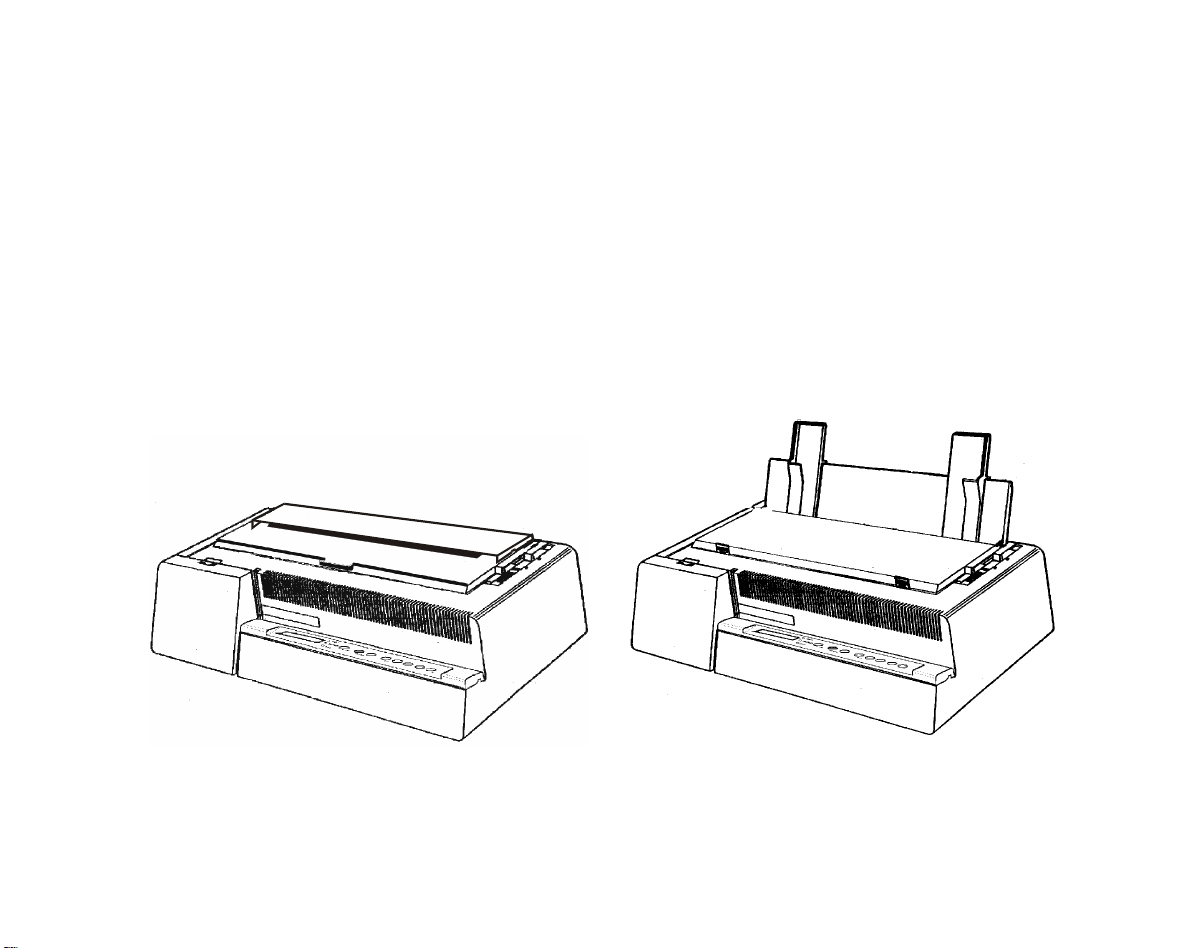
Getting to Know Your Printer ..............................1
Printer Features ................................................................1
4051/4051N plus............................................................1
4056/4056N plus............................................................2
Unpacking Your Printer
Printer Parts ......................................................................4
4051/4056 plus Models – Front View..........................4
4051N/4056N plus Models – Front View ...................5
All Models – Rear View................................................6
Setting Up Your Printer........................................7
Choosing a Suitable Location
Printer Assembly
Ribbon Cartridge Installation
Paper Chute Installation (4051/4056 plus models only)
........................................................................................ 13
Host Computer Connection
Parallel Connection
Serial Connection
Software Driver Selection
Power Connection
Selecting the Display Language..........................20
Configuring the Printer ........................................21
Operator Panel Presentation
Display Messages
Indicators
Function Keys
Buzzer
Printer Setups .......................................................36
Entering the Printer Setups
Moving within the Printer Setups
........................................................................ 26
............................................................................ 35
.......................................................3
.............................................7
.................................................................8
..........................................8
............................................... 15
....................................................... 15
.......................................................... 16
.................................................. 17
.............................................................. 18
............................................. 21
......................................................... 21
................................................................ 27
........................................... 36
.................................. 36
Leaving the Printer Setups
Power on Configuration Setup
Entering the Power-On Configuration
Program Setup
Entering the Program Setup
Paper Handling......................................................68
Paper Specifications
Fanfold Paper
Cut Sheets
Cut Sheets
Loading Cut Sheets
Fanfold Paper
Inserting Fanfold Paper
Parking Fanfold Paper
Switching From Fanfold Paper to Cut Sheet
Top of Form Adjustment
Tear Off Line Adjustment
Printer Maintenance and Troubleshooting.........83
Cleaning the Printer
Replacing the Ribbon Cartridge
Printing the Self Test
Error Handling
Options ..................................................................89
LAN Connection
Automatic Sheet Feeder (4051/4056 plus models only)
Unpacking Automatic Sheet Feeder
Preparing the Printer
Automatic Sheet Feeder Assembly
Paper Specifications
Paper Loading
How to Keep the Automatic Sheet Feeder Clean
Removing the Automatic Sheet Feeder
Problem Solving
Printer Specifications.........................................112
...................................................................54
..........................................................68
.................................................................68
......................................................................69
..........................................................................70
.....................................................................73
............................................................83
..........................................................86
....................................................................87
.................................................................89
..............................................................102
...........................................................111
............................................37
...........................................37
...........................38
..........................................54
.......................................................70
.................................................73
...................................................79
................80
....................................................81
...................................................82
........................................84
.............................90
......................................................91
..............................94
....................................................100
.....................109
..90
......109
v
Page 6

Page 7

GGeettttiinngg ttoo KKnnooww YYoouurr PPrriinntteerr
PPrriinntteerr FFeeaattuurreess
44005511//44005511NN pplluuss
Common Features
• 9 Needle Print Head
• Draft printing at 480 cps and in Letter Quality at 120 cps
• IBM Proprinter XL III, EPSON FX Series (ESC/P) emulation
• High resolution printing at 240 x 144 dots per inch
• Operator panel with a Liquid Crystal Display (16 alpha-numeric characters), three leds and
eight function keys to control the operating printer state
• Easy usage through the Operator Panel and through software commands
• Printing of the commonly used bar codes
• Plug & Play capability for 95/98/2000®
• Bidirectional IEEE 1284 parallel interface and standard serial RS-232/C-RS-422/A interface.
4051 plus Model Specific Features
• 136 columns
• An Automatic Sheet Feeder (option) that handles large quantities of cut sheets and allows
simultaneous use of fanfold paper
• An optional Ethernet 10/100 Base-T interface that coexists with the serial interface.
4051N plus Model Specific Features
• 100 columns
1
Page 8

44005566//44005566NN pplluuss
Models Common Features
• 24 Needle Print Head
• Draft printing at 480 cps and in Letter Quality at 133 cps
• IBM Proprinter XL24E, XL24E AGM, EPSON LQ 1050/2550 (ESC/P) emulation
• High resolution printing at 360 x 180 dots per inch
• Operator panel with a Liquid Crystal Display (16 alpha-numeric characters), three leds and
eight function keys to control the operating printer state
• Easy usage through the Operator Panel and through software commands
• Printing of the commonly used bar codes
• Plug & Play capability for 95/98/2000®
• Bidirectional IEEE 1284 parallel interface and standard serial RS-232/C-RS-422/A interface.
4056 plus Model Specific Features
• 136 columns
• An Automatic Sheet Feeder (option) that handles large quantities of cut sheets and allows
simultaneous use of fanfold paper
• An optional Ethernet 10/100 Base-T interface that coexists with the serial interface.
4056N plus Model Specific Features
• 100 columns
2
Page 9
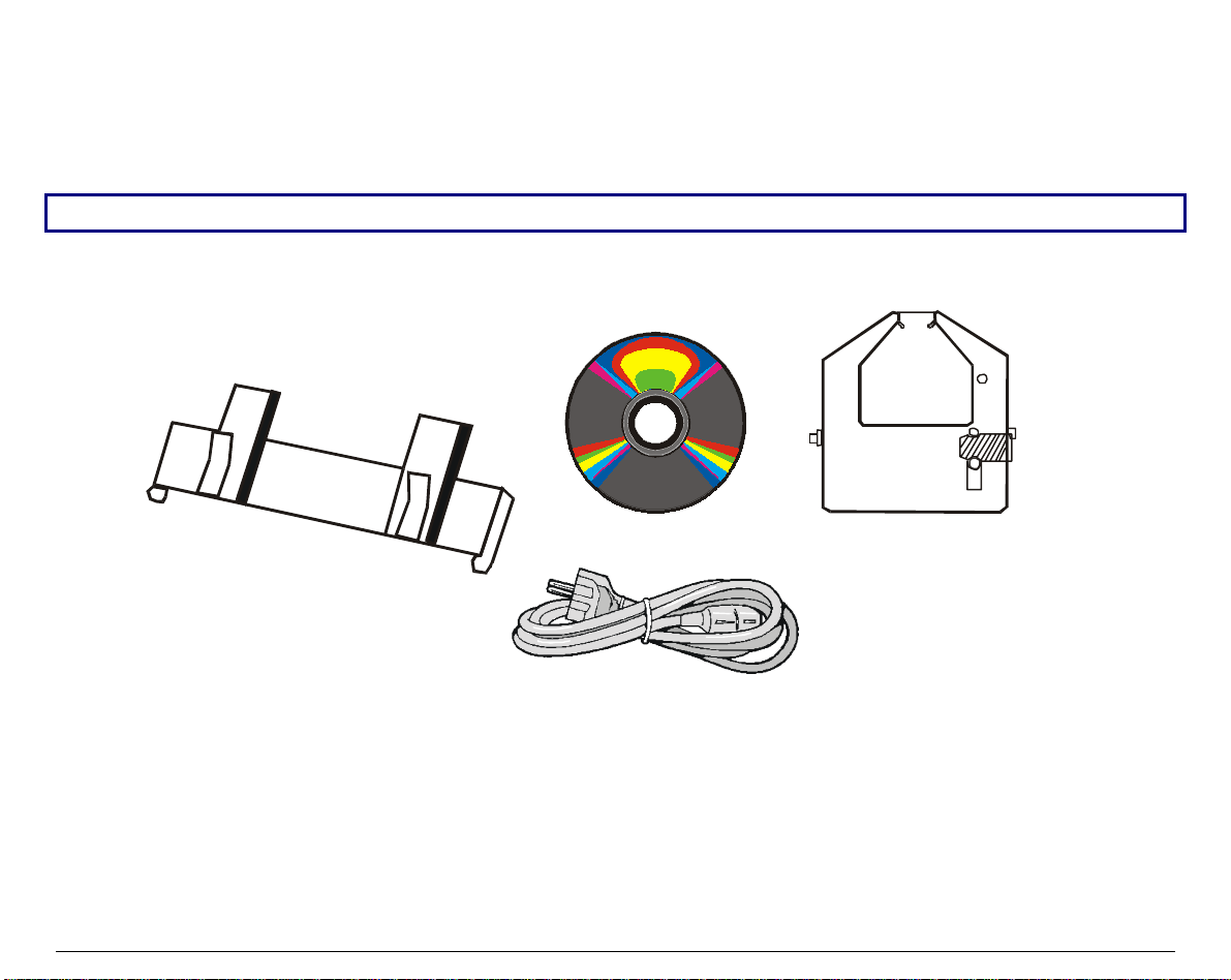
UUnnppaacckkiinngg YYoouurr PPrriinntteerr
Together with the Installation Guide and the CD-ROM with the User Manual, the following
items are included in the box:
Notify any damage to your supplier.
Paper Chute
(4051/4056 plus only)
CD-ROM
Ribbon Cartridge
Black Ribbon - 3 M crt
Power Cable
3
Page 10
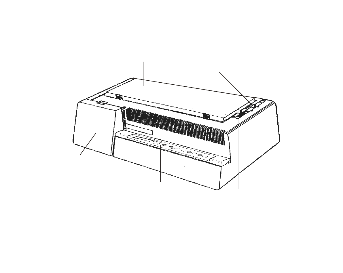
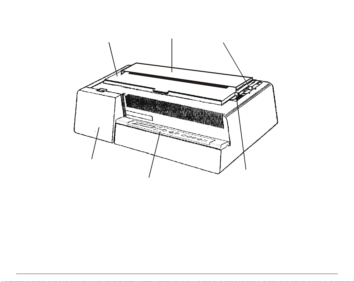
PPrriinntteerr PPaarrttss
44005511//44005566 pplluuss MMooddeellss –– FFrroonntt VViieeww
Printer Cover
Interface B oard C ov er
Operator Panel
Drive Se lection Lev er
Pap er Thickness Le ver
4
Page 11
44005511NN//44005566NN pplluuss MMooddeellss –– FFrroonntt VViieeww
Printer Cover
Interface Board Cover
Paper Chute
Operator P anel
Drive Selection Lever
Paper Thickness Lever
5
Page 12
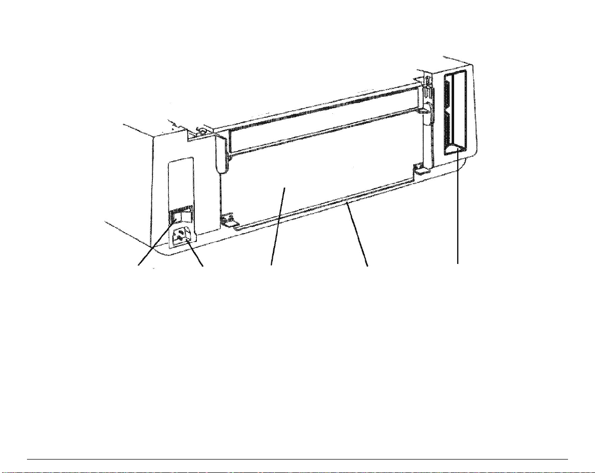
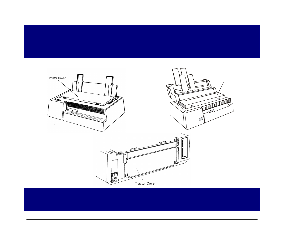
AAllll MMooddeellss –– RReeaarr VViieeww
Power Switch
Power Socket
Tractor Cov er
6
Rear Paper Entry Slot
Interface Socket
Page 13

SSeettttiinngg UUpp YYoouurr PPrriinntteerr
CChhoooossiinngg aa SSuuiittaabbllee LLooccaattiioonn
Consider the following points when you choose the location for your printer:
• The distance between the printer and the host computer must not exceed the length of the
interface cable;
• The location must be sturdy, horizontal and stable;
• Your printer must not be exposed to direct sunli ght, extreme heat, cold, humidity or dust
see “Printer Specifications” section later;
• You need a power outlet compatible with the plug of the printer’s power cord. The voltage of
the outlet must match the voltage shown on the printer’s Rating Plate.
After selecting an installation location, install the printer making sure that there is sufficient
space for operation.
7
Page 14
PPrriinntteerr AAsssseemmbbllyy
RRiibbbboonn CCaarrttrriiddggee IInnssttaallllaattiioonn
It is advisable to insert the ribbon cartridge while the printer is turned off.
However, your printer can be turned on during this procedure, but do not forget that it must be
disabled to print (Wait displayed and
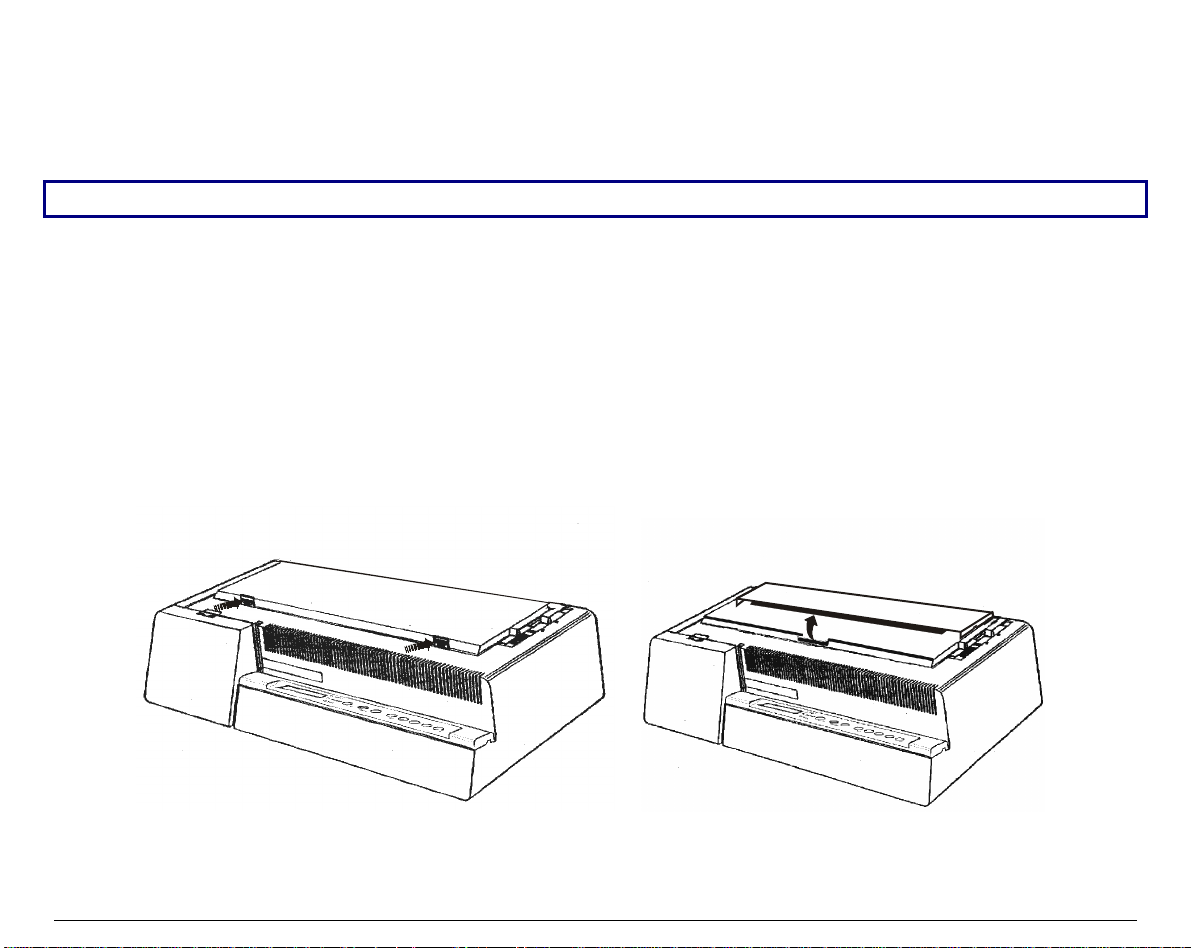
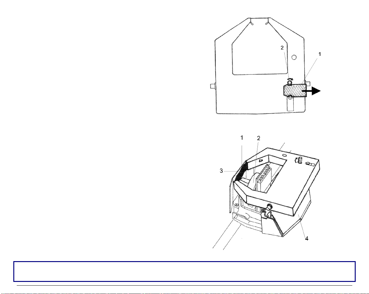
1. Remove the printer cover by pressing simultaneously the two buttons in the front part of the
cover.
• If your printer is the 4051N plus or the 4056N plus model, do not remove but lift the
printer cover.
READY
led turned off).
4051/4056 plus Models 4051N/4056N plus Models
8
Page 15
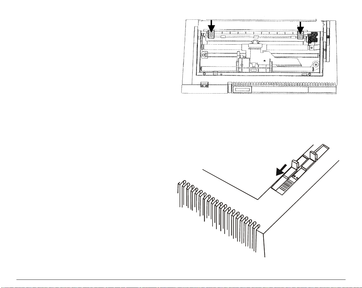
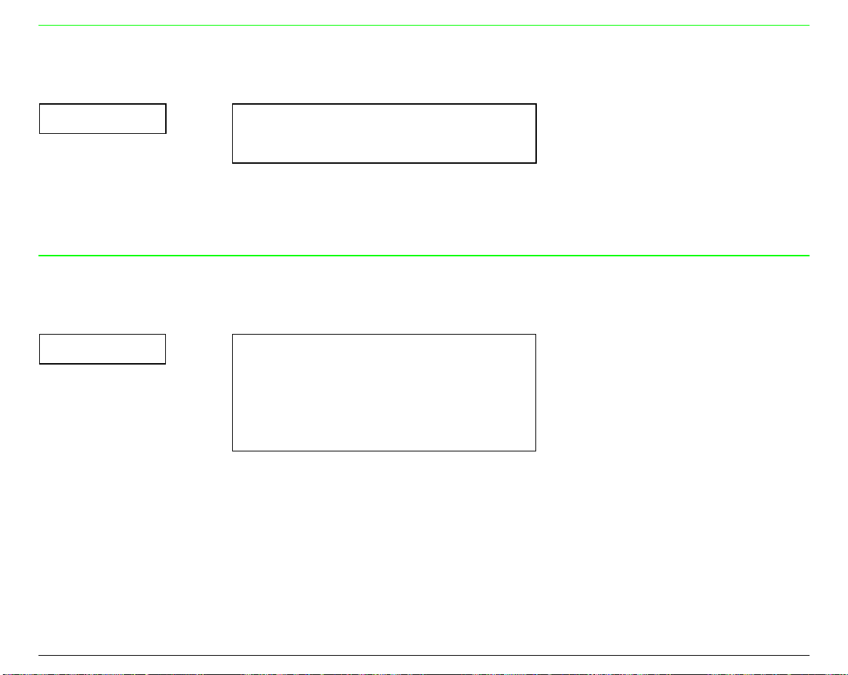
2. If you are inserting the ribbon cartri dge for
the first time, do not forget to complete the
unpacking procedure by taking off the
plastic hooks that fix the paper ba il.
3. Pull the paper thickness lever tow ards the
front of the printer to facilitate ribbon
insertion.
9
Page 16
4. Remove the new ribbon cartridge from its
bag. Remove and discard the holdfast (1)
that blocks the ribbon. Turn the tension
knob (2) to tighten the ribbon.
5. Insert the ribbon (1) between the print
head (2) and the print hea d mask (3). Lay
the cartridge over the printer carriage (4).
Make sure that the two pins on each side of the cartridge are positioned over t he retaining clips of
the printer carriage.
10
Page 17
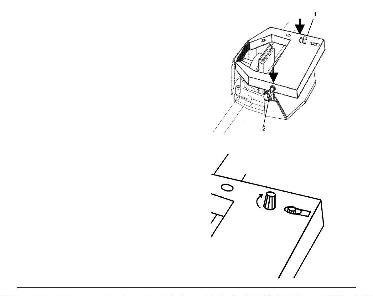
6. Push the cartridge gently down while
turning the tension knob (1). Make sure
that the cartridge clicks into place (2).
7. To tighten the ribbon, turn the tension
knob in the direction shown by the arrow
on the ribbon cartridge
11
Page 18
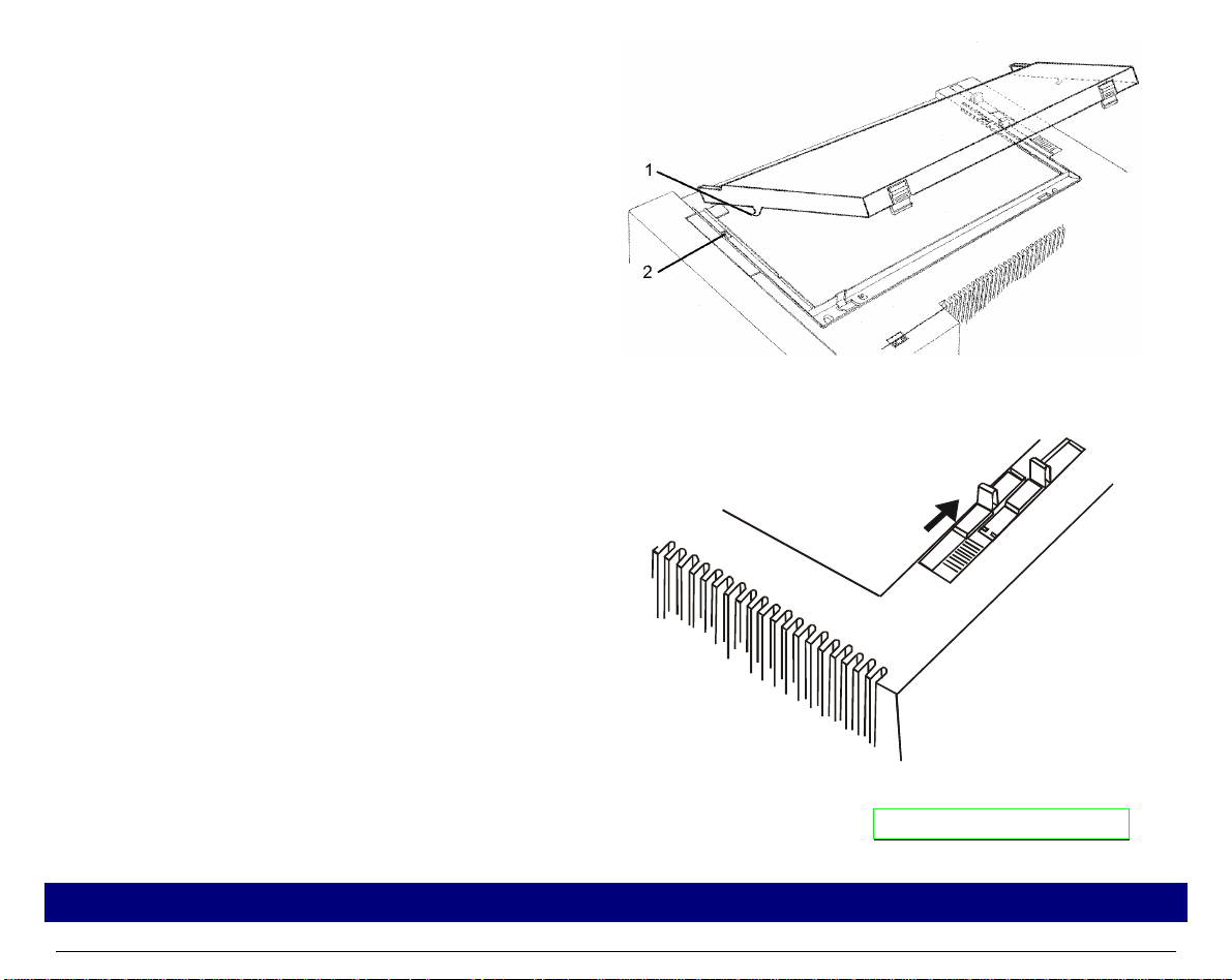
8. Replace the pri nter cover by first inserting
the hooks (1) into the appropriate grooves
(2) and then lower the cover ensuring that
clicks in place.
• If your printer is the 4051N plus or the
4056N plus model, simply lower the
printer cover to close it.
9. Move the paper thickness lever according to the paper type:
• If a cut sheet is loaded move the lever
towards the back of the printer.
• If a multicopy-chemical paper is
loaded, first move the lever completely
towards the back of the printer, then 1
notch towards the front of the printer
for each copy.
• If a carbon multicopy-paper is loaded,
first move the lever completely
towards the back of the printer, then 2
notches towards the front of the
printer for each copy.
Now, you can load the paper and print your first test document, see “Printing the Self Test ”. If
the pattern does not satisfy your expectation, a djust the paper thickness lever again.
When printing on multicopy-paper follow the above instructions to avoid damaging the print head.
12
Page 19
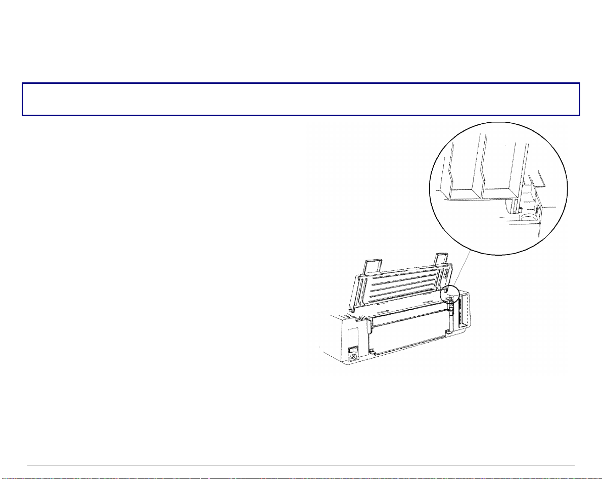
PPaappeerr CChhuuttee IInnssttaallllaattiioonn ((44005511//44005566 pplluuss mmooddeellss oonnllyy))
The paper chute is provided with the 4051plus and 4056 plus printers. To install the paper chute
in the printer follow this sequence:
To insert the paper chute correctly, make sure that you are in front of the print er and that you hold
the paper chute in the front position.
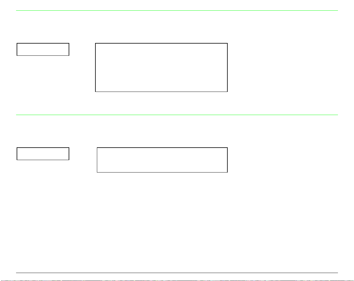
1. Insert the hook on the left side of the paper
chute in the groove situated near the paper
entry slot.
The figure shows the back of the printer and
the paper chute in the back position for a
good view of the hook and groove. For this
reason, you will see the left side of the paper
chute shown on the right.
13
Page 20
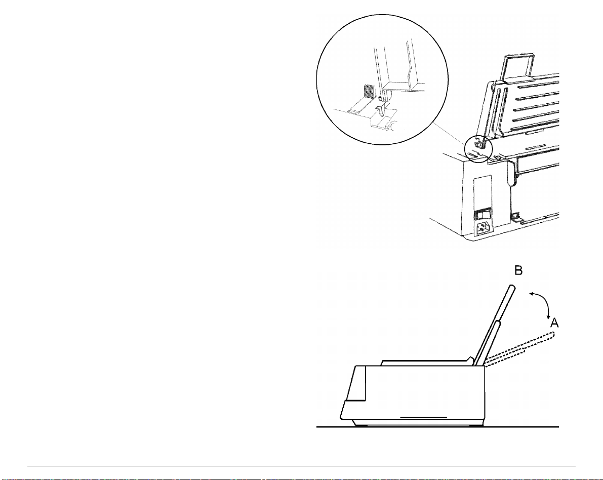
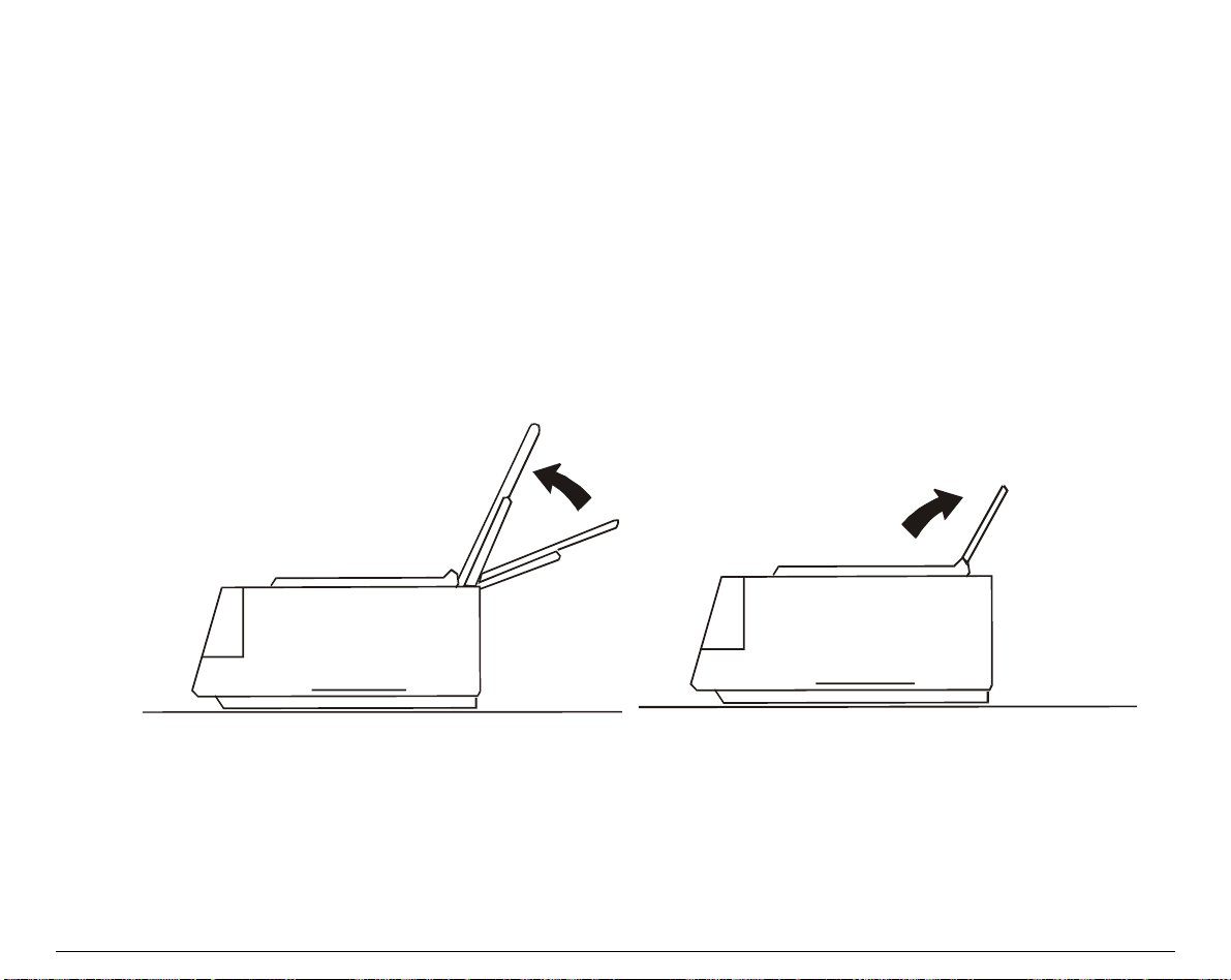
2. Flex the paper chute towards the front of
the printer and insert the hook on the
opposite side of the paper chute in the
corresponding groove.
This printer accessory may assume two
different positions according to the paper
type: down position for fanfold paper (A) and
raised position for cut sheet (B).
3. If you wish to position the paper chute
down, lift it towards the back of the printer
and push it gently down until it stops. If you
wish to place the paper chute in the raised
position, lift it and hook it firmly.
14
Page 21
HHoosstt CCoommppuutteerr CCoonnnneeccttiioonn
This printer can be connected to your host computer via two available interfaces. The interface
connectors are located on the rear of the printer.
• A bidirectional IEEE1284 parallel interface
• A RS-232C/422A serial interface
Make sure that both printer and host computer are switched off.
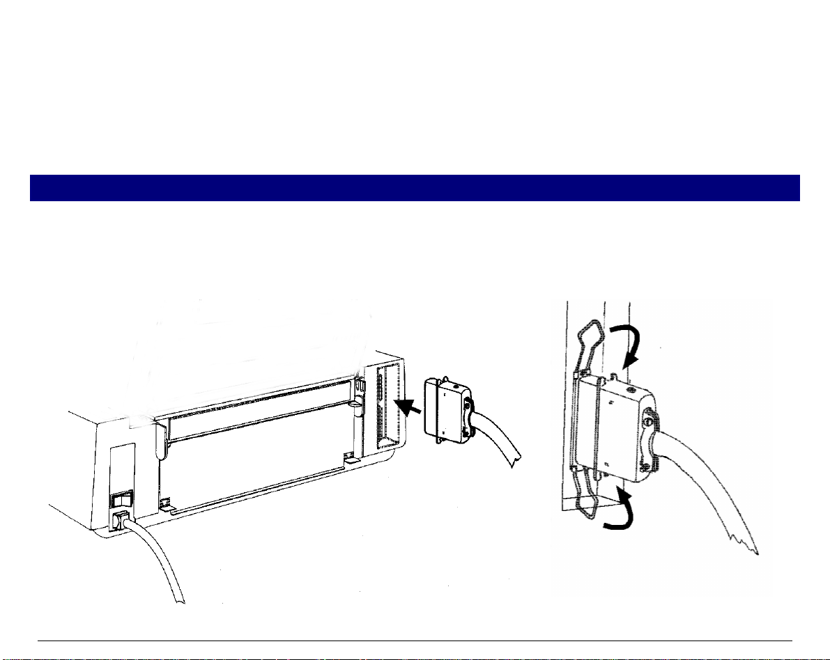
PPaarraalllleell CCoonnnneeccttiioonn
Insert the parallel interface cable into the parallel connector and fasten it by means of the clips.
15
Page 22
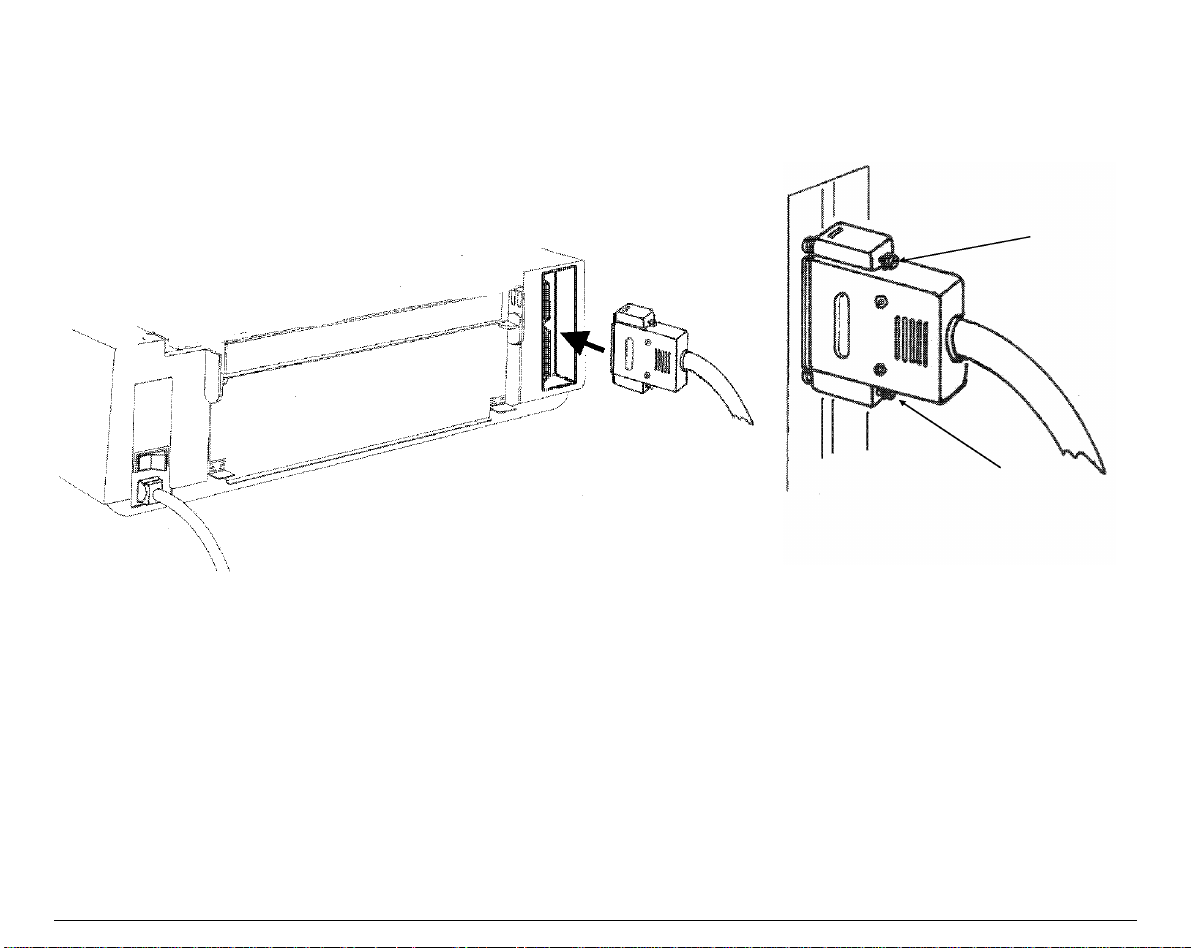
SSeerriiaall CCoonnnneeccttiioonn
Insert the serial interface cable into the serial connector, and fasten it by means of the two
screws (use the screwdriver).
16
Page 23

SSooffttwwaarree DDrriivveerr SSeelleeccttiioonn
At this point it is necessary to configure your printer for your application package. The
installation procedures depend upon the host environment:
Follow the instructions in the readme file you find on the CD-ROM.
In a WINDOWS® 95/98/2000 environment the printer supports the Plug & Play feature.
The printer drivers of all Compuprint printers can be found at the Internet Address
http://www.compuprint.net/drivers
17
Page 24
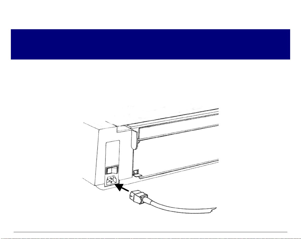
PPoowweerr CCoonnnneeccttiioonn
Make sure that the power outlet matches the power rating of the printer. See th e name plate of th e
printer, that you find in the rear of the printer.
Always use a grounded outlet.
Make sure that the power outlet is near the printer location and easily accessible.
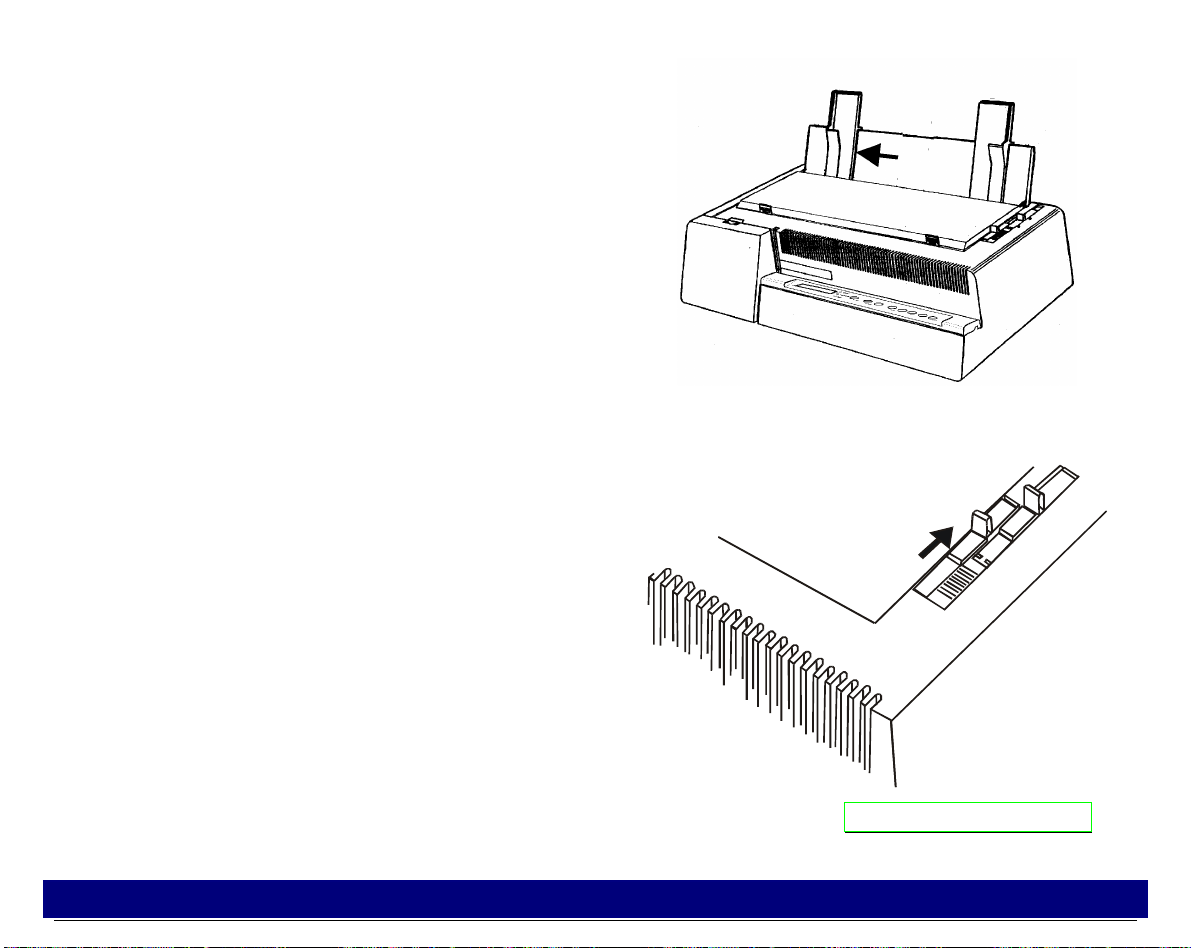
1. Make sure that the power switch at the rear of the printer is in the "printer off" position.
Insert one end of the power cable plug into the printer connector placed on the rear of the
printer.
18
Page 25
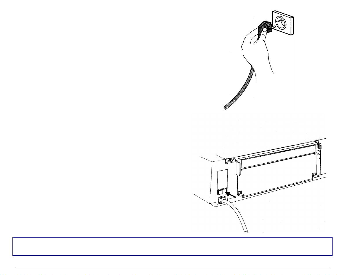
2. Insert the other end of the power cable in a
convenient outlet.
3. To turn the printer on, press the part of the
power switch that now is up. The print head
moves and stops at about 6.5 inches from the left
side of the printer and the indicators on the
operator panel light up for a few seconds.
Every time the printer is turned off and you need to turn it on again, wait 3 seconds before turning
it on.
19
Page 26
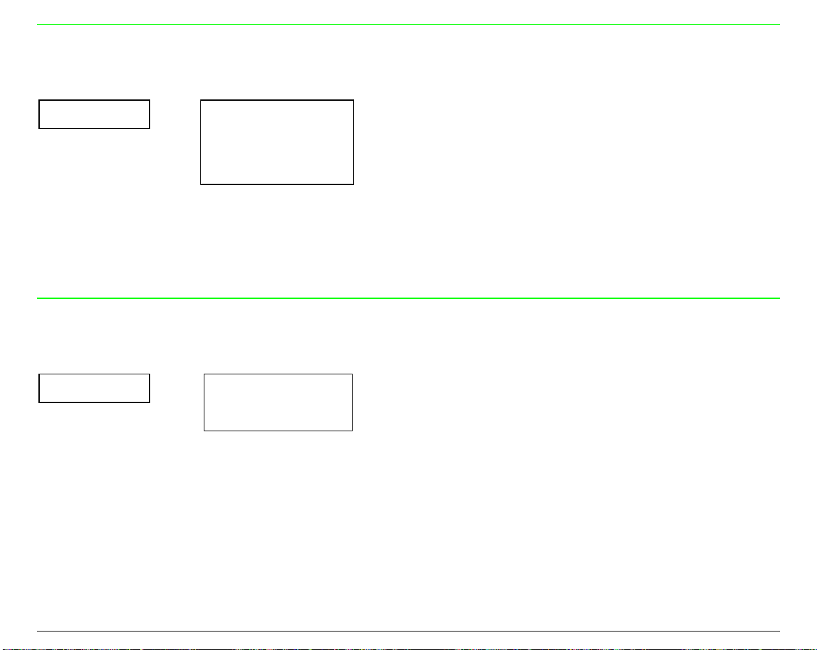
SSeelleeccttiinngg tthhee DDiissppllaayy LLaanngguuaaggee
The display messages for this printer can be displayed in two different languages: English
(Default) and Italian.
To select the language that y ou prefer, proceed as follows:
1. Enter the Power on Configuration procedure.
• Make sure that the printer is turned off.
• Keep the
phase the following message will be displayed:
2. Press the → key to select the function.
3. Press the ↓ key until the language first level function is displayed:
4. Press the → key to select the function. The following message will be displayed:
The symbol ‘ * ’ means that the shown parameter is the selected one, in this case it is the
default value.
5. Press the → key to select it.
6. Press the
message will appear in the selected language.
PROGRAM
PROGRAM
key pressed while you turn on the printer. After the initialization
INSTALLATION
LANGUAGE
* English
key to exit the Power on Configuration procedure. From now the display
20
Page 27
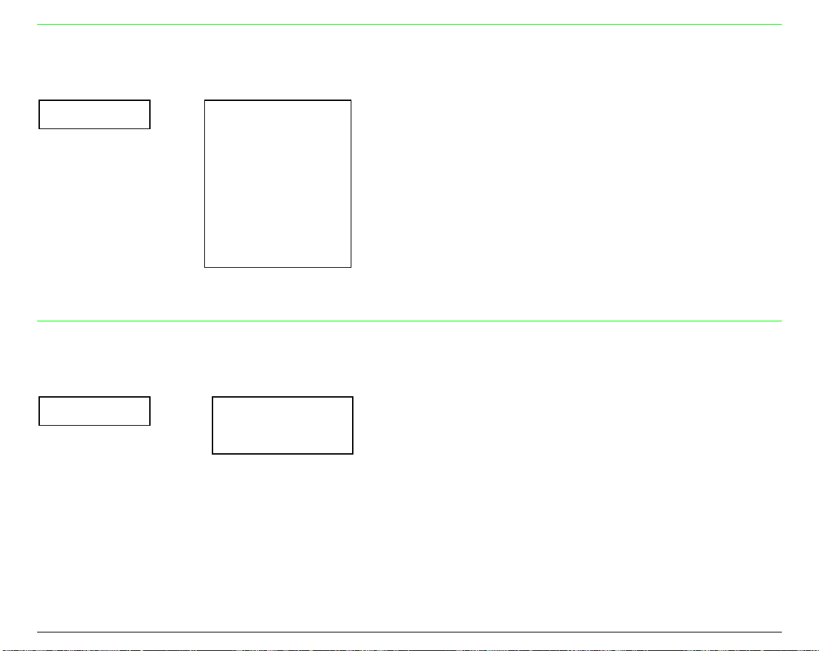
CCoonnffiigguurriinngg tthhee PPrriinntteerr
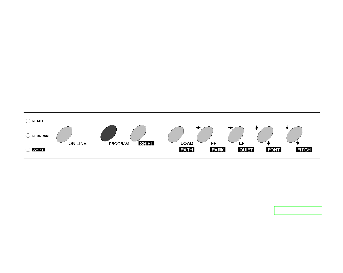
OOppeerraattoorr PPaanneell PPrreesseennttaattiioonn
The operator panel consists of three elements:
• Display: you can see on the display various messages usually regarding the printing
functions.
• Indicators: give information about the operating state of the printer.
• Function keys: allow you to change operating state of the printer as necessary.
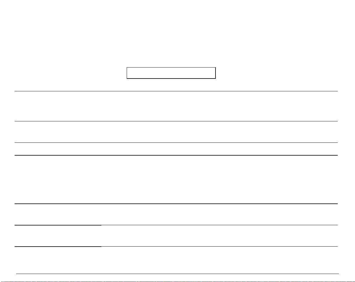
DDiissppllaayy MMeessssaaggeess
The display messages can be divided into three main groups:
STATUS MESSAGES
SETUP MESSAGES
give information about the current operating printer state.
are displayed during the printer setup procedure. See " Printer Setups "
later in this section.
ERROR MESSAGES
signal the printer faults.
21
Page 28
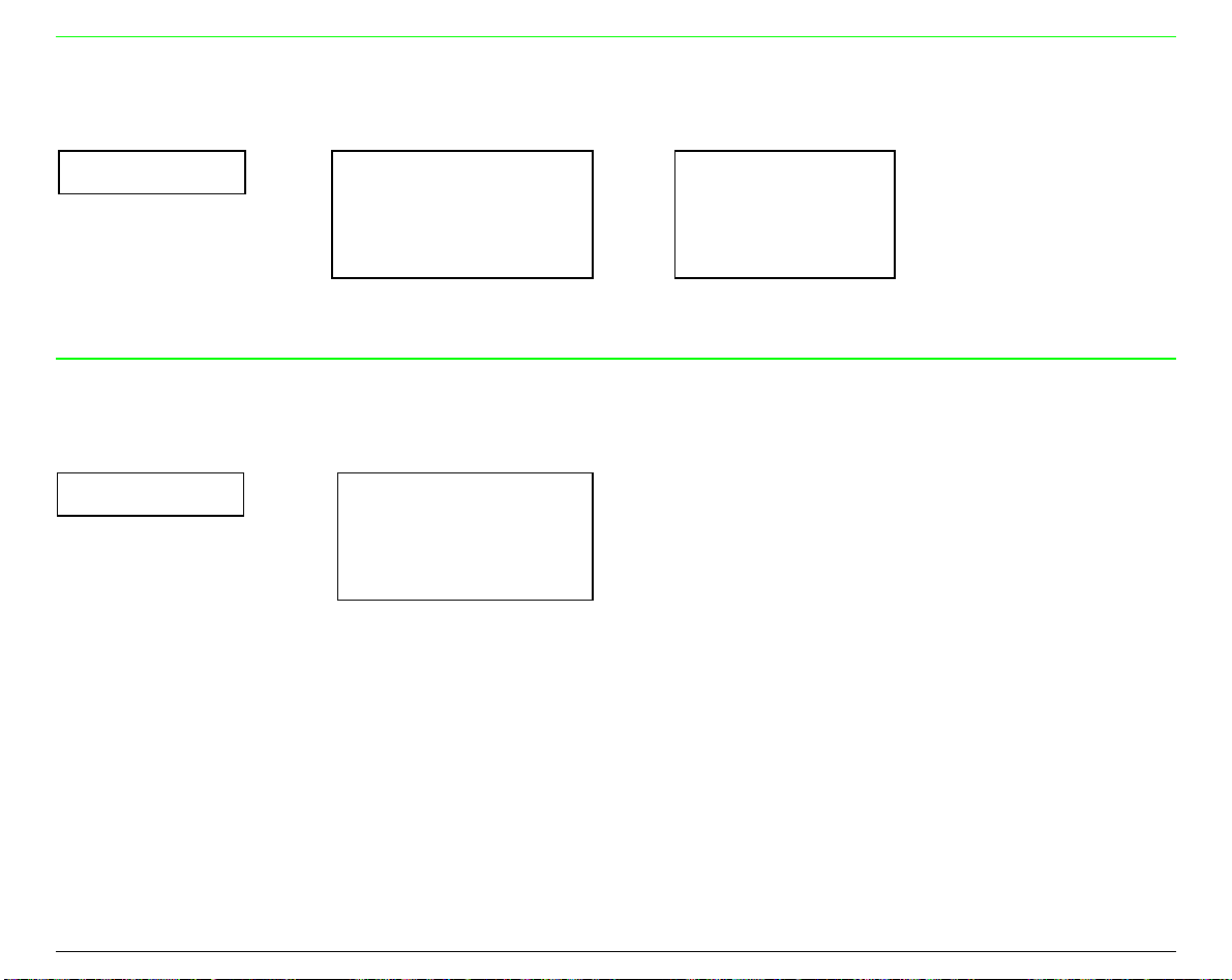
Basic Indications on the Display
When turning the printer on, after the message 405x plus, the display indicates the printer
status (Ready, Wait, Busy, Quiet), the current macro (M1, M2, M3, M4) and the selected
emulation (IBM XL III or EPSON FX for the 4051/4051N plus printers and IBM XL 24E, IBM
XL24 AGM and EPSON LQ for the 4056/4056N plus printers) as follows:
Ready M1-EPS
The following list shows y o u the status and error messages in alphab e tical order:
1.Enable path SS
2.Remove paper
1.Tear-off paper
2.Remove paper
2. Park paper
4051 plus or
4051N plus or
4056 plus or
4056N plus
Bin 1
Bin 1/2
Bin 2
Displayed when Bin 1, Bin 2 (4051/4056 plus models only) or
Manual paper path loading is not successful. Check the position of the
selection lever (towards the back of the printer for sing le sheets).
Displayed when the fanfold paper to pa rk is too l ong. Tea r the printed
paper and press the
PARK
key again.
Displayed when Park operation is not successful.
This message appears on the display immediately after turning the
printer on to indicate that it is initializing to its power on setting. The
print head moves to its initial position. The printer is logically
disconnected from the host and is disabled to receive data. The
READY
indicator is turned off.
Displayed when ASF Bin 1 paper path is selected (4051/4056 plus
models only).
Displayed when ASF Bin 1/2 paper paths are selected (4051/4056
plus models only).
Displayed when ASF Bin 2 paper path is selected (4051/4056 plus
models only).
22
Page 29

Buffer cleared
Displayed after input buffer clearing (all the stored data are erased).
Call Service
Carriage error
Check connection
Check interface
Check its moving
Check line
Comm. failure
Data lost
Enable path FF
Enable path SS
Displayed in rolling mode together with the failure message to
indicate a call to Service.
Displayed when there is an unrecoverable carriage error. This means
that the printer carriage does not move correctly. When the
Carriage error message is displayed, the i ndicator
READY
blinks.
Check that the ribbon cartridge is not used up neither damaged.
Displayed when a DSR, DCD, or CTS signal fault occurs.
Displayed when an Input bu ffer overflow occurs
Displayed when a carriage fault occurs.
Displayed when a communication error occurs.
Displayed when a communication error occurs
Displayed when an input b u ffer overflow occurs.
This message appears on the display immediately after switching
Manual path to Fanfold path. Place the dri ve selection lever in the
fanfold position.
This message appears on the display immediately after switching
Fanfold path to Manual path. Place the dri ve selection lever in the
single sheet position.
Fanfold
This is one of the messages that will be displayed when you press
PATH
(Shift function). Press the
SHIFT
key to select the fanfold paper
path.
23
Page 30

Fanfold thru ASF
This is one of the messages that will be displayed when you press
(Shift function). Press the
SHIFT
key to select the handling of the
PATH
fanfold paper with the Automatic Sheet Feeder (option) installed
(4051/4056 plus models only).
Initializing
Invalid keypress
Labels
Load
Loading paper
Manual
NVM changed
Parking paper
Press any button
Press Park
Printer failure
Displayed while the printer is turned on.
An invalid pressing of a key has occurred.
This is one of the messages that will be displayed when you press
(Shift function). Press the
SHIFT
key to select the fanfold paper with
PATH
adhesive label loading.
Displayed when a paper out occurs.
Displayed when there is a paper loading request (fanfold or cut
sheet).
This is one of the messages that will be displayed when you press
PATH
(Shift function). Press the
SHIFT
key to select the manual cut
sheet path.
Displayed when NVM contents has been changed.
Generic status message for all parking operations.
Generic user intervention message.
PARK
You are requested to press the
key.
Displayed in case of fault during the initialization.
Printing test
Processing
Displayed while the self-test is running.
Generic wait message for an operation.
24
Page 31

Quiet --- OFF
Displayed when the Quiet function is not selected.
Quiet --- ON
Ready M1-EPS
Release button
Remove paper
Self-test
Serial I/F error
Shift
Stand-by
Top cover open
Wait M1-EPS
Displayed when the Quiet function is selected.
Displayed when the printer is on line and ready to print.
Generic user intervention message.
Displayed when Eject operation is not successful.
Displayed during the self test procedure. You can select the test
procedure keeping pressed the
ON LINE
key while turning on the
printer. The printer is disabled to recei ve data from the host and the
READY
LINE
key.
indicator is unlit. To stop test procedure press again the
ON
Displayed when a DSR, DCD, or CTS signal fault occurs.
Displayed every time that the
SHIFT
key is pressed to indicate that
the Shift function is selected.
Displayed when the printer is in stand-by status.
Displayed as long as the top cover is open.
Displayed when the printer is unab le to print. The indicator
READY
is
unlit.
25
Page 32

IInnddiiccaattoorrss
READY
PROGRAM
SHIFT
Lit When the printer is enabled to receive and print data.
Blinking The printer is unable to receive and print data (Wait message
displayed) but there is still data in the input buffer.
Unlit When the printer is unable to print because:
• the test procedure is running;
• the printer initialization is running.
Lit When the
PROGRAM
function of the operator panel keys has been
selected and enabled.
Unlit When the normal function of the operator panel keys is selected.
Lit When the
SHIFT
function of the operator panel keys has been selected
and enabled.
Unlit When the normal function of the operator panel keys is selected.
26
Page 33

FFuunnccttiioonn KKeeyyss
Each key can select one of the three available function modes: Normal, Program or Shift.
• The Normal function does not require previous action to be selected.
• The Program function is selected by pressing the
disabled. Keep pressed this key while turning on the printer until the message Release
button is displayed, the Power on Configuration Setup will be entered. Pressing this key
while the printer is in Wait (indicator
• The Shift function is selected b y pressing the
the Program function is selected.
READY
unlit) the Program Setup will be entered.
SHIFT
PROGRAM
key. This function key is disabled when
key when the printing is
27
Page 34

ON LINE Key
ON LINE
Normal Function Pressing this key you will obtain different results depe nding on the
printer status:
When the
•
the stop of the printing at the end of the current line; the
READY
indicator is lit on, press ing this ke y you will caus e
READY
indicator blinks if there is s ome data left in the Inpu t buffe r,
otherwise the indicator is turned off and the
message will be
Wait
displayed.
When the
•
printing will be enabled and the
Pressing this key while powering the printer on, the message
•
Printing test
READY
is unlit or is blinking pres sing this key the
READY
indicator is turned on.
is displayed and the check test is executed. If you
want to stop the self-test press this key again.
Program
Function
Pressing this key you will obtain diff eren t resu lts dep end ing on the
interface configuration (par allel or se rial interf ace).
In parallel configuration, the inf ormation in the In put buff er is res et
•
and the
In serial configuration, the in formation in the In put buff er is res et.
•
Buffer cleared
message will be displayed.
28
Page 35

LOAD/PATH Key
LOAD
Normal Function If you press this key while the printer is unable to pr int you will
obtain the following effects:
PATH
No action if paper is already present. The
•
Invalid keypress
will be displayed
If paper is not present, pressing this key, the paper is loaded
•
according to the drive selection lever selection
If the optional ASF is installed, the paper is loaded from the
•
selected ASF bin (4051/4056 plus models only).
Shift Function This key selects the paper paths and it is enabled when the
printing is disabled. The display shows the paper path you can use.
If you want to select the displayed paper path, release the key and
do not press it again within 1 sec. The available paper paths are
For 4051/4056 plus models:
•
Fanfold - Labels - Fanfold
Thru Asf - Manual - Bin 1 - Bin 2
For 4051N/4056N plus models:
•
Manual
Fanfold - Labels -
29
Page 36

FF/PARK Key
FORM FEED
PARK
←
Normal Function Pressing this key while the printer is offline causes:
The paper, if loaded, advances at new page or, if park ed, is
•
positioned on the first printable line.
The cut sheet, if loaded, is ejected (max. 21 inches) or a new cut
•
sheet will be loaded.
Shift Function No action if the paper is not present.
Invalid keypress
is displayed. Fanfold paper, present in the printer, is set in parking
position.
Parking paper
is displayed. Cut sheet, already inserted,
is ejected.
Program
Function
The
←
Setup.
function allows you to get at the previous level of the
message
Printer
30
Page 37

LF/QUIET Key
LINE FEED
→
QUIET
Normal Function It is available when printing is disabled. This function caus es a
paper advancement to the next printable line. Keeping pressed this
key for more than a seco nd, you will obtain the cont inuous
execution of paper advancing.
Shift Function It allows a noise level reduction. Keepin g pres sed this ke y
-OFF
and
Quiet--- ON
will be displayed in rolling mode. If you
want to enable this function, release this key when the message
Quiet---ON
Quiet
OFF
. To disable this function release this key when
is displayed. If
is displayed. On the display remains the message
Quiet ---
QUIET
mode is selected while the printer is
printing , it will be activated at the end of the c urr ent line.
Program Function
The function → allows you to get to the next level of the Printer
Setup.
When
SELECT MACRO
is displayed, pressing → key the selected
and operating macro will be disp layed. Us ing the ↑ and the ↓ keys
you will be able to display all the selectable macro s. (
MACRO n
displayed). Pressing the → key the displayed macro is selected and
using the ↑ and ↓ keys the selectable parameters will be d isplayed .
Quiet--
is
Select the parameter to be modified by pressing the → key (the
selected and active value is marked with an asterisk (*) on the left
of the value itself), press the ↑ and the ↓ keys to select it then press
key to confirm it.
→
31
Page 38

FONT Key
↑
FONT
↑
Normal Function
Shift Function The Font function will be enabled. This function allows you to
Program Function
The ↑ (MICRO FEED FORWARD) function is available when the
printer is not printing and causes a forward micro feed of the
paper. Keeping pressed this key for a second, the paper will
advance in continuous mode at the speed of 3.5 ips (slew speed).
choose among the selectable fonts. Keeping pressed this key or
pressing it within 1 second, the fonts will be scrolled. Release this
key when the name of the requested font is displayed or do not
pressed again within a second. The font messa ges are:
Courier - Gothic - OCR-A - OCR-B
printers and
Draft - Courier – Gothic – Boldface –
for the 4051/4051N plus
Prestige – Script -Presentor - OCR-A - OCR-B
Draft -
for the
4056/4056N plus printers.
The ↑ (Up arrow) key allows you to scrol l upwards the functions
that are present in a function level, or to scroll upwards the
function values if you are at selection level. The numeric values
are incremented.
32
Page 39

PITCH Key
↓
Normal Function
The ↓ function is available when the printing is not printing and
allows to move backwards the paper with a micro advancement.
Keeping pressed this key for a second, the paper moves backwards in
continuous mode at the speed of 3.5 ips (slew speed).
PITCH
Shift Function The pitch function allows you to select the available horizontal
spacing. Keeping pressed this key or pressing it within a second the
spacings will be scrolled. Release the key when the desired spacing is
displayed or do not press it again within a second. Available
horizontal spacings (CPI):
- 17.1 - 20
↓
Program Function
The ↓ function allows to scroll downwards the functions that are in a
5 - 6 - 7.5 - 8.55 - 10 - 12 - 15
level, or to scroll downwards the function values if you are at a
selection level. The numeric values are d ecr emented.
33
Page 40

PROGRAM Key
PROGRAM
Normal Function Keeping pressed this key while you turn on the printer you will
enter
printer is unable to print, (indicator
Program Setup
The
Pressing this key when the
Program Function is disabled and the indicator turned off.
Program
Function
If you press this key while you are in the
exit the configuration mode saving the function values that have
been changed.
If changes occurred, the message
Now, if you press the
the new values will be only used as current ones. (When you turn
off the printer you will loose any change you have made).If you
press the → key, you will exit the Program Function and the
modified values of the selected macro will be stored in a permanent
mode.
SHIFT Key
Power on Configuration Setup
and the Program Function of keys are enabled.
PROGRAM
indicator is turned on when the function is enabled.
PROGRAM
PROGRAM
. Pressing this key when the
READY
unlit) you will enter the
indicator is turned on, the
Program Setup
SAVE MACRO?
key you will exit the function and
will be displayed.
you will
SHIFT
Normal Function Press the
SHIFT
long as a key available for this function is p ress ed.
Shift Function Pressing the
Shift
is unlit.
SHIFT
indicator lights and the messag e
key to select the Shift Function of the keys. The
will be displayed as
SHIFT
when the
SHIFT
Shift
indicator is lit and the message
is displayed, disables the Shift function. The
34
SHIFT
indicator
Page 41

BBuuzzzzeerr
This printer is provided with a buzzer to indicate particular conditi ons according to the problem
detected:
• 1 short "beep" (0,25 sec): the BEL code has been sent; when the buzzer sound stops, the
printer returns to normal operation.
• Continuous "beep": the printer cover has been raised when the printer is enabled to print.
Close the cover and make sure that the message Wait (
before raising the cover again.
• 4 long "beeps": a fault condition has occurred. See later "Error Handling".
• 4 short "beeps": A condition of paper end or paper removal has occurred.
READY
indicator unlit) is di splayed
35
Page 42

PPrriinntteerr SSeettuuppss
You can customize the printer depending on your needs via the Power on Configuration Setup
and the Program Setup procedures.
EEnntteerriinngg tthhee PPrriinntteerr SSeettuuppss
PROGRAM
The
• Keep pressed the
Configuration Setup.
• Press the
Program Setup.
When you enter the desired Printer Setup, the Program functions, described above the key area,
key allows to enter the Printer Setups.
PROGRAM
PROGRAM
key when the printer is disabled (
MMoovviinngg wwiitthhiinn tthhee PPrriinntteerr SSeettuuppss
The arrow keys ↑, ↓, ←, → are used to move within the different functions inside the Printer
Setups.
• Use the ↓ key to scroll forward the functions (next ones) and ↑ to scroll them backwards
(previous ones).
• Use the → key to select the next function or the value and ← to display the previous one.
• When the desired value is display e d, press the → key to select it.
key while powering the printer on to enter the Power on
READY
will be enabled.
indicator unlit) to enter the
36
Page 43

LLeeaavviinngg tthhee PPrriinntteerr SSeettuuppss
Whenever you wish to leave the current Printer Setup, proceed as follows:
• In the Power-On Configuration, press the
automatically stored. The printer leaves the Power on Configuration Setup and is disabled to
print (
• In the Program Setup, press the
MACRO? will be displayed. Press the
current settings (When the printer will be turned off they will be lost) or the key → to store
the changes in a permanent way.
READY
indicator unlit).
PROGRAM
PROGRAM
PPoowweerr oonn CCoonnffiigguurraattiioonn SSeettuupp
The default values are marked with an asterisk (*) on the left. These are the available functions:
INSTALLATION
INTERFACE
PRINT STATUS
RECALL FACTORY
This function contents general parameters such as Protocol, Emulation and the
display language.
This function defines the interface physical type and communication features.
This function allows to print the current printer configuration.
This function allows to reset the factory default values.
PROGRAM
key and if any change occurred the message SAVE
key and the modified values will be used as
key and the new settings will be
37
Page 44

EEnntteerriinngg tthhee PPoowweerr--OOnn CCoonnffiigguurraattiioonn
1. Make sure that the printer is turned off.
2. Keep pressed the
PROGRAM
button key while turning on the printer. The 4051 plus, 4051N
plus, 4056 plus or 4056N plus message will be displayed then Release button message.
3. Release the button key and the following message will be displayed:
INSTALLATION
INSTALLATION Function
Emulation Selection
RECALL FACTORY BUZZER
↑
INSTALLATION → or ← PROTOCOL
↓
INTERFACE
IBM XL III
IBM XL 24E
IBM XL 24E AGM
IBM XL III emulation (4051/4051N plus models only - d efault).
IBM XL 24E emulation (4056/4056N plus models only - d efault).
IBM XL 24E AGM emulation (4056/4056N plus mode ls only).
↑
↓
IBM/EPSON MODE
or ← IBM xx
→
EPSON xx
or ↓
↑
or ↓
↑
EPSON FX
EPSON LQ
EPSON FX Series emulation (4051/4051N plus models only).
EPSON LQ 1050/2550 emulation (4056/4056N plus models only).
38
Page 45

IBM Mode
PROTOCOL
↑
IBM MODE
↓
EPSON MODE
IBM C-SET (1/2)
NATION
20 CPI
or ← IBM C-SET (1/2) ↑ or ↓ → or
→
IBM character sets selection.
IBM national character sets selection.
IBM compressed printing selection.
-- IIBBMM CChhaarraacctteerr SSeettss
20 CPI
↑
IBM C-SET (1/2) → or ← IBM set 1 (*)
↓
NATION
IBM set 1
IBM CS1 character set selection.
NATION
20 CPI
IBM set 2
IBM set...
←
or ↓ → or
↑
or ↓ → or
↑
or ↓
↑
or ↓
↑
←
←
CP 437 ...
No
IBM set 2
IBM CS2 character set selection.
39
Page 46

-- IIBBMM NNaattiioonnaall CChhaarraacctteerr SSeettss
IBM C-SET (1/2)
↑
NATION
↓
20 CPI
or ← CP 437 (*)
→
...
ISO 8859/15
or ↓
↑
or ↓
↑
or ↓
↑
Selection of the IBM National Character Sets:
CP 437(*)
CP 853
CP 863
CP 877
MAZOWIA
ISO 8859/6
CP437 G
CP 855
CP 864
CP 1250
ISO 8859/1
ISO 8859/7
The CP 858 and ISO 8859/15 character sets contain the Euro character.
-- IIBBMM CCoommpprreesssseedd PPrriinntt
NATION
↑
20 CPI
↓
IBM C-SET (1/2)
No
Yes
→
or ← No (*)
Yes
The compressed printing is performed at 17.1 cpi.
The compressed printing is performed at 20 cpi.
96 GREEK
CP 857
CP 865
CP 1251
ISO 8859/2
ISO 8859/8
CP850
CP 858
CP 866
CP 1252
ISO 8859/3
ISO 8859/9
CP851
CP 860
CP 867
GOST
ISO 8859/4
ISO 8859/15
CP 852
CP 862
CP 876
TASS
ISO 8859/5
or ↓
↑
or ↓
↑
40
Page 47

EPSON Mode
PROTOCOL
↑
EPSON MODE → or ← NATION
↓
LINE MODE
NATION
EPSON C-SET
EPSON national character sets selec tion
EPSON character sets selection.
-- EEPPSSOONN NNaattiioonnaall CChhaarraacctteerr SSeettss
EPSON C-SET
↑
NATION
↓
EPSON C-SET
or ← USA (*)
→
EPSON C-SET
or ↓ → or
↑
or ↓ → or
↑
←
←
...
ISO 8859/15
or ↓
↑
or ↓
↑
or ↓
↑
USA
Italics ....
Selection of the EPSON National character sets:
USA (*) FRANCE GERMANY ENGLAND DENMARK1 SWEDEN
ITALY SPAIN 1 JAPAN NORWAY DENMARK 2 SPAIN 2
LATIN A1 CP 437(*) CP437 G 96 GREEK CP850 CP851
CP 852 CP 853 CP 855 CP 857 CP 858 CP 860
CP 862 CP 863 CP 864 CP 865 CP 866 CP 867
CP 876 CP 877 CP 1250 CP 1251 CP 1252 GOST
TASS MAZOWIA ISO 8859/1 ISO 8859/2 ISO 8859/3 ISO 8859/4
ISO 8859/5 ISO 8859/6 ISO 8859/7 ISO 8859/8 ISO 8859/9 ISO 8859/15
41
Page 48
The CP 858 and ISO 8859/15 character sets contain the Euro character.
-- EEPPSSOONN CChhaarraacctteerr SSeettss
NATION
↑
EPSON C-SET → or ← Italic
↓
NATION
Italic
Graphic 1
Graphic 2
Graphic 1
Graphic 2 (*)
EPSON Italic character set s election.
EPSON Graphic 1 character s et selec tion.
EPSON Graphic 2 character s et selec tion.
Line Mode
EPSON MODE
↑
LINE MODE
↓
TEAR/VIEW MODE
or ← LF=LF, CR=CR (*) ↑ or ↓
→
CR=LF+CR
LF=LF+CR
LF&CR=LF+CR ↑ or ↓
or ↓
↑
or ↓
↑
or ↓
↑
or ↓
↑
or ↓
↑
LF=LF,CR=CR
CR=LF+CR
If the printer receives a LF code, it only performs a line feed. If the printer receives a
CR code, performs a carriage return.
If the printer receives a CR code, it performs a carriage return followed by a line feed.
If the printer receives a LF code, it performs a line feed.
42
Page 49

LF=LF+CR
If the printer receives a LF code, it performs a line feed followed by a carriage return. If
the printer receives a CR code, it only performs a carriage return.
LF&CR=LF+CR
If the printer receives a LF code or a CR code, it performs both a line feed and a
carriage return.
Tear/View Mode
LINE MODE
↑
TEAR/VIEW MODE → or ← Auto.advance 1s (*) ↑ or ↓
↓
LANGUAGE
Auto.advance 1s ... 5s
...
Auto.advance 5s
Manual advance
No tear
or ↓
↑
or ↓
↑
or ↓
↑
or ↓
↑
Paper moves automatically to the tear/view position after the specified timeout (1s. to 5s.)
Manual advance
No tear
Paper moves to the tear/view position using the
Tear/view mode is disabled. It is useful to print labels or paper that bac kward
movements may cause a paper jam.
ON LINE
key.
43
Page 50
Display Language Selection
TEAR/VIEW MODE
↑
LANGUAGE
↓
BUZZER
or ← English (*)
→
Italiano
or ↓
↑
or ↓
↑
This function selects the language of the display messages: in English or Italian language.
Enable/Disable Buzzer
LANGUAGE
↑
BUZZER
↓
PROTOCOL
or ← Enabled (*)
→
Disabled
or ↓
↑
or ↓
↑
This function enables or disables the buzzer.
44
Page 51

INTERFACE Function
Interface Type
INSTALLATION HIGH GUARD LEVEL
↑
INTERFACE
↓
PRINT STATUS I/F TIME-OUT
Automatic
Parallel
Serial
→ or ← INTERFACE TYPE → or ← Automatic (*) ↑ or ↓
The interface type is automatically selected according to the data transmission.
Parallel interface selection.
Serial interface selection.
↑
↓
Parallel
Serial
or ↓
↑
or ↓
↑
Interface Time-out
INTERFACE TYPE
↑
I/F TIME-OUT
↓
INPUT BUFFER
or ← 2 seconds (*)
→
...
30 seconds
or ↓
↑
or ↓
↑
or ↓
↑
This function defines the time duration (2 to 30 sec.) after which the interface switches to the
other.
45
Page 52

Input Buffer Size
I/F TIME-OUT
↑
INPUT BUFFER
↓
PARALLEL MODE
or ← 256 (DLL)
→
...
32K (No DLL) (*) ↑ or ↓
or ↓
↑
or ↓
↑
This function selects the input buffer size with one of the following values: 256, 4K, 8K, 16K or
32 K. The 16K and the 32K values do not allow the DLL. The most suitable value for the DLL
function is 256 (DLL).
Parallel I/F Mode
INPUT BUFFER
↑
PARALLEL MODE → or ← Parallel CX ↑ or ↓
↓
AUTOFEED SIGNAL
Bidirectional (*) ↑ or ↓
Parallel CX
Bidirectional
Parallel interface in Centronics monodirectional mode.
Parallel interface in IEEE 1284 bidirectional standard mode.
46
Page 53

AUTOFEED Signal
PARALLEL MODE
↑
AUTOFEED SIGNAL → or ← Enabled
↓
SLCT-IN SIGNAL
Disabled (*)
or ↓
↑
or ↓
↑
Enabled
Disabled
The parallel interface uses the AUTOFEED signal.
The parallel interface ignores the AUTOFEED s ignal.
SELECT-IN Signal
AUTOFEED SIGNAL
↑
SLCT-IN SIGNAL
↓
SERIAL TYPE
Enabled
Disabled
The parallel interface uses the SELECT-IN signal.
The parallel interface ignores the SELEC T-IN signal.
or ← Disabled (*) ↑ or ↓
→
Enabled
or ↓
↑
47
Page 54

Serial Interface Type
SLCT-IN SIGNAL
↑
SERIAL TYPE
↓
SERIAL MODE
or ← RS232C (*) ↑ or ↓
→
RS422A
or ↓
↑
This function selects the serial interface type: RS-232/C or RS-422/A.
Serial Connection Mode
SERIAL TYPE
↑
SERIAL MODE
↓
BAUD RATE
or ← Local (*)
→
Remote
or ↓
↑
or ↓
↑
This function selects the serial connection type: local or remote.
48
Page 55
Baud Rate
SERIAL MODE
↑
BAUD RATE
↓
WORD LENGTH
or ← 600 bps
→
...
9600 bps (*)
...
38400 bps
or ↓
↑
or ↓
↑
or ↓
↑
or ↓
↑
or ↓
↑
This function selects the data transmission speed in b its per second (bps). The values availab le
are: 600, 1200, 2400, 4800, 9600, 19200, 38400.
Data Format
BAUD RATE
↑
WORD LENGTH
↓
PARITY BIT
or ← 7 bit
→
8 bit (*)
or ↓
↑
or ↓
↑
This function selects the data format, using 7 or 8 bits.
49
Page 56

Parity Check
WORD LENGTH
↑
PARITY BIT
↓
BUFFER CONTROL
or ← Even
→
Odd
Mark
Space
None (*)
or ↓
↑
or ↓
↑
or ↓
↑
or ↓
↑
or ↓
↑
Even
Odd
Mark
Space
None
Parity check is enabled for even parity.
Parity check is enabled for odd parity.
Parity check disabled and the transmitted parity bit is always in Mark state.
Parity check disabled and the transmitted parity bit is always in Space s tate.
Parity check (for 8 data bits only).
Buffer Control
PARITY BIT
↑
BUFFER CONTROL → or ← DTR
↓
ROBUST XON
XON/XOFF (*) ↑ or ↓
or ↓
↑
This function selects the buffer control protocol: DTR or XON/XOFF.
50
Page 57

Robust XON
BUFFER CONTROL
↑
ROBUST XON
↓
HIGH GUARD LEVEL
or ← No (*)
→
Yes
or ↓
↑
or ↓
↑
This function selects the execution of Robust XON.
High Guard Level
ROBUST XON
↑
HIGH GUARD LEVEL → or ← 10% Buffer Size
↓
INTERFACE TYPE
...
or ↓
↑
or ↓
↑
90% Buffer Size (*) ↑ or ↓
Selects the percentage of the input buffer to fix to the High Guard Level signal.
51
Page 58
PRINT STATUS Function
• Press the → key to select the function.
The message Printing test will displayed while the following output will be printed:
405x plus: CONTROLLER:78XXXXXX Rel.:x.xx GENERATOR: 78XXXXXX Rel.:x.xx
OPTIONS CURRENT VALUES MACRO1* MACRO2 MACRO3 MACRO4
FONT Draft Draft Draft Draft Draft
DRAFT MODE. Normal Normal Normal Normal Normal
VERTICAL PITCH 6 lpp 6 lpp 6 lpp 6 lpp 6 lpp
LPI LOCK Disabled Disabled Disabled Disabled Disabled
FORM LENGTH 66 lines 66 lines 66 lines 66 lines 66 lines
TOP MARGIN Line #1 Line #1 Line #1 Line #1 Line #1
BOTTOM MARGIN Line #66 Line #66 Line #66 Line #66 Line #66
HORIZONTAL PITCH 10 cpp 10 cpp 10 cpp 10 cpp 10 cpp
CPI LOCK Disabled Disabled Disabled Disabled Disabled
LEFT MARGIN Column #1 Column #1 Column #1 Column #1 Column #1
RIGHT MARGIN Column #136 Column #136 Column #136 Column #136 Column #136
Column #100 Column #100 Column #100 Column #100 Column #100
SLASHED ZERO No No No No No
MULTICOPY No No No No No
PRINT DIRECTION Soft. control Soft. control Soft. control Soft. control Soft. control
INTERFACE PRINT ADJUSTMENT INSTALLATION
INTERFACE TYPE Automatic BIDI. ALIGNEMENT. Offset: 0 PROTOCOL IBM XL xx
I/F TIME-OUT 2 seconds TOP OF FORM 0/72 inches
INPUT BUFFER 32 k (No DLL)
PARALLEL MODE Bidirectional 0/90 inches NATION CP437
AUTOFEED SIGNAL Disabled
SLCT-IN SIGNAL Disabled TEAR PERFO ALIGN 0/72 inches
SERIAL TYPE RS232C
SERIAL MODE Local 0/90 inches NATION USA
BAUD RATE 9600 bps
WORD LENGTH 8 bit TEAR/VIEW MODE Auto.advance1s
PARITY BIT None LANGUAGE English
BUFFER CONTROL XON/XOFF BUZZER Enabled
ROBUST XON No
HIGH GUARDLEVEL 90% Buffer Size
(4051/4056 plus models) (4051/4056 plus models) (4051/4056 plus models) (4051/4056 plus models) (4051/4056 plus models)
(4051N/4056N plus models) (4051N/4056N plus models)
(4051N/4056N plus models
)
(4051N/4056N plus models
)
(4051N/4056N plus models
IBM MODE
(4051/4051N plus models)
(4056/4056N plus model)
IBM SET-C (1/2) IBM set 1
20 CPI No
EPSON MODE
(4051/4051N plus models)
(4056/4056N plus model)
EPSON C-SET Graphic 2
LINE MODE LF=LF,CR=CR
)
52
Page 59
RECALL FACTORY Function
• Press the → key to select this function. The values of the functions return to the factory
default setting.
All values of the functions are reset to the factory def ault ones in both Power on Configurat ion
Setup and Program Setup.
These are the default values:
OPTIONS CURRENT VALUES MACRO1* MACRO2 MACRO3 MACRO4
FONT Draft Draft Draft Draft Draft
DRAFT MODE. Normal Normal Normal Normal Normal
VERTICAL PITCH 6 lpp 6 lpp 6 lpp 6 lpp 6 lpp
LPI LOCK Disabled Disabled Disabled Disabled Disabled
FORM LENGTH 66 lines 66 lines 66 lines 66 lines 66 lines
TOP MARGIN Line #1 Line #1 Line #1 Line #1 Line #1
BOTTOM MARGIN Line #66 Line #66 Line #66 Line #66 Line #66
HORIZONTAL PITCH 10 cpp 10 cpp 10 cpp 10 cpp 10 cpp
CPI LOCK Disabled Disabled Disabled Disabled Disabled
LEFT MARGIN Column #1 Column #1 Column #1 Column #1 Column #1
RIGHT MARGIN Column #136 Column #136 Column #136 Column #136 Column #136
(4051/4056 plus models)
Column #100 Column #100 Column #100 Column #100 Column #100
(4051N/4056N plus models) (4051N/4056N plus models)
SLASHED ZERO No No No No No
MULTICOPY No No No No No
PRINT DIRECTION Soft. control Soft. control Soft. control Soft. control Soft. control
INTERFACE PRINT ADJUSTMENT INSTALLATION
INTERFACE TYPE Automatic BIDI. ALIGNEMENT. Offset: 0 PROTOCOL IBM XL xx
I/F TIME-OUT 2 seconds TOP OF FORM 0/72 inches IBM MODE
INPUT BUFFER 32 k (No DLL)
PARALLEL MODE Bidirectional
AUTOFEED SIGNAL Disabled
SLCT-IN SIGNAL Disabled TEAR PERFO ALIGN 0/72 inches EPSON MODE
SERIAL TYPE RS232C
SERIAL MODE Local 0/90 inches NATION USA
BAUD RATE 9600 bps
WORD LENGTH 8 bit TEAR/VIEW MODE Auto.advance1s
PARITY BIT None LANGUAGE English
BUFFER CONTROL XON/XOFF BUZZER Enabled
ROBUST XON No
HIGH GUARDLEVEL 90% Buffer Size
(4051/4056 plus models) (4051/4056 plus models) (4051/4056 plus models) (4051/4056 plus models)
(4051N/4056N plus models
(4051/4051N plus models)
0/90 inches
(4056/4056N plus model)
(
4051/4051N plus models)
(4056/4056N plus model)
)
(4051N/4056N plus models
IBM SET-C (1/2) IBM set 1
)
(4051N/4056N plus models
NATION CP437
20 CPI No
EPSON C-SET Graphic 2
LINE MODE LF=LF,CR=CR
)
53
Page 60

PPrrooggrraamm SSeettuupp
The default values are marked with an asterisk (*). These are the available functions:
SELECT MACRO
PRINT ADJUSTMENT
PRINT STATUS
HEXADECIMAL DUMP
EEnntteerriinngg tthhee PPrrooggrraamm SSeettuupp
To enter the Program Setup procedure, proceed as follows:
1. Make sure that the printer is not enabled to print (
2. Press the
PROGRAM
This function defines four different macros and allows to configure the
printer for different job types.
This function allows the adjustment of the mechanical parameters and the
tuning of the first printing line.
This function allows to print the current printer configuration.
This function allows to enable the Hexadecimal Dump mode.
READY
PROGRAM
key (
indicator lit). The following message will be displayed:
SELECT MACRO
indicator unlit).
54
Page 61

SELECT MACRO Function
MACRO SELECTION
HEXADECIMAL DUMP MACRO 4
↑
SELECT MACRO → or ← MACRO 1 → or ← FONT
↓
PRINT ADJUSTMENT MACRO 2
↑
↓
DRAFT MODE
VERTICAL PITCH
LPI LOCK
FORM LENGTH
TOP MARGIN
BOTTOM MARGIN
HORIZONTAL PITCH
CPI LOCK
LEFT MARGIN
RIGHT MARGIN
SLASHED ZERO
MULTICOPY
PRINT DIRECTION
or ↓
↑
or ↓
↑
or ↓
↑
or ↓
↑
or ↓
↑
or ↓
↑
or ↓
↑
or ↓
↑
or ↓
↑
or ↓
↑
or ↓
↑
or ↓
↑
or ↓
↑
or ↓
↑
This function allows to select one of the four available print environments.
55
Page 62
Font Selection
PRINT DIRECTION
↑
FONT
↓
DRAFT MODE
→
or ← Draft (*)
...
OCR-B
or ↓
↑
or ↓
↑
or ↓
↑
Selects the type of character to use: Draft, Courier, Gothic, OCR-A, OCR- B for the 4051/4051N
plus models and Dra ft, Courier, Gothic, Prestig e, Presentor, OCR-A, OCR-B, Scri pt, Boldface for
the 4056/4056N plus models. OCR-A and OCR-B may be selected only when the nonproportional pitch is selected. Boldface may be selected only when the proportional pitch is
selected.
Draft Mode
FONT
↑
DRAFT MODE
↓
VERTICAL PITCH
or ← Normal (*)
→
High speed
or ↓
↑
or ↓
↑
This function selects the draft printing speed: Normal or High Speed.
56
Page 63
Vertical Spacing
DRAFT MODE
↑
VERTICAL PITCH → or ← 6 lpi (*)
↓
LPI LOCK
...
12 lpi
3 lp/30 mm
...
12 lp/30 mm
or ↓
↑
or ↓
↑
or ↓
↑
or ↓
↑
or ↓
↑
or ↓
↑
This function determines the density with which the lines are printed according to different
units: lines printed per inch (6, 8, 12 lpi) or lines per 30 mm (3, 4, 6, 8, 12 lp/30 mm).
Lpi Lock
VERTICAL PITCH
↑
LPI LOCK
↓
FORM LENGTH
or ← Enabled
→
Disabled (*)
or ↓
↑
or ↓
↑
Enabled
Disabled
Vertical spacing can be changed only by the op erator panel keys .
Vertical spacing can be changed by software or by operator panel k eys.
57
Page 64
Form Length
LPI LOCK
↑
FORM LENGTH
↓
TOP MARGIN
or ← NUMBER OF LINES ↑ or ↓
→
A4 (11.6 inches)
A5 (8 inches)
or ← 1 line (*)
→
or ↓ ...
↑
or ↓ 126 lines ↑ or ↓
↑
or ↓
↑
or ↓
↑
This function selects the physical page length in n° of lines (1 to 126 lines at 1/6”) or in standard
formats (A4 or A5).
Top Margin
FORM LENGTH
↑
TOP MARGIN
↓
BOTTOM MARGIN
or ← Line #1 (*)
→
...
Line #X
or ↓
↑
or ↓
↑
or ↓
↑
This function selects the top margin defined as n° of lines (at 1/6 ”). The value X corresponds to
the n° of lines set in the FORM LENGTH function.
58
Page 65

Bottom Margin
TOP MARGIN
↑
BOTTOM MARGIN
↓
HORIZONTAL PITCH
or ← Line #1
→
...
Line #66 (*)
...
Line #126
or ↓
↑
or ↓
↑
or ↓
↑
or ↓
↑
or ↓
↑
This function selects the bottom margin defined as n° of lines (at 1/6”). The value X corresponds
to the n° of lines set in the FORM LENGTH function.
Horizontal Spacing
BOTTOM MARGIN
↑
HORIZONTAL PITCH → or ← 5 cpi
↓
CPI LOCK
...
10 cpi (*)
...
20 cpi
Prop. Spacing ↑ or ↓
or ↓
↑
or ↓
↑
or ↓
↑
or ↓
↑
or ↓
↑
This function sets the horizontal spacing at the following values: 5, 6, 7.5, 8.55, 10, 12, 15, 17.1,
20 cpi or the proportional spacing.
59
Page 66
Cpi Lock
HORIZONTAL PITCH
↑
CPI LOCK
↓
LEFT MARGIN
or ← Enabled
→
Disabled (*)
or ↓
↑
or ↓
↑
Enabled
Disabled
Horizontal spacing is selected only by operator panel (
Horizontal spacing is selected by the operator panel (
PITCH
PITCH
key).
key) or by software.
Left Margin
CPI LOCK
↑
LEFT MARGIN
↓
RIGHT MARGIN
or ← Column#1 (*)
→
...
Column#136
Column#100
(4051/4056 plus models)
(4051N/4056N plus models)
or ↓
↑
or ↓
↑
or ↓
↑
↑ or ↓
This function sets the left margin defined as n° of columns. The physical margin position
depends on the selected horizontal spacing.
60
Page 67
Right Margin
LEFT MARGIN
↑
RIGHT MARGIN
↓
SLASHED ZERO
or ← Column#1
→
...
Column#136 (*)
Column#100 (*)
(4051/4056 plus models)
(4051N/4056N plus models)
or ↓
↑
or ↓
↑
or ↓
↑
↑ or ↓
This function sets the right margin defined a s number of columns. The physical margin position
depends on the selected horizontal spacing.
Zero Character Typeface
RIGHT MARGIN
↑
SLASHED ZERO
↓
MULTICOPY
or ← Yes
→
No (*)
or ↓
↑
or ↓
↑
This function selects the zero character printing wi th ( Yes) or without slash (No).
61
Page 68

Multicopy Form
SLASHED ZERO
↑
MULTICOPY
↓
PRINT DIRECTION
or ← Yes
→
No (*)
or ↓
↑
or ↓
↑
This function selects the printing on multicopy format paper (Yes) or on normal paper (No).
Print Direction
MULTICOPY
↑
PRINT DIRECTION → or ← Unidirectional ↑ or ↓
↓
FONT
Bidirectional
Soft. control (*) ↑ or ↓
or ↓
↑
This function selects the print direction: unidirectional, bidirectional o controlled by software.
62
Page 69

PRINT ADJUSTMENT Function
Bidirectional Print Alignment
SELECT MACRO. TEAR PERFO ALIGN
↑
PRINT ADJUSTMENT → or ← BIDI. ALIGNMENT → or ← Offset: +6 ↑ or ↓
↓
PRINT STATUS TOP OF FORM
↑
↓
...
Offset: -6
or ↓
↑
or ↓
↑
This function adjusts the bidirectional printing in a range between - 6 and +6. When the
previous value is changed, the printer prints two ‘|’ lines to control the final output.
63
Page 70

Top of Form (ToF)
BIDI. ALIGNMENT
↑
TOP OF FORM
↓
TEAR PERFO ALIGN
or ← 0/72 inches
→
0/90 inches
...
792/72 inches
990/90 inches
(4051/4051N plus models)
(4056/4056N plus models)
(4051/4051N plus models)
(4056/4056N plus models)
or ↓
↑
or ↓
↑
or ↓
↑
or ↓
↑
or ↓
↑
This function adjusts the top of the form in n/72 inch (4051/4051N plus models) or n/90 inch
(4056/4056N plus models). The values range between 0 and 792 (4051/4051N plus models) or
between 0 and 990 (4056/4056N plus models). At value selection level, the printer prints a
**x/72** string (4051/4051N plus models) or a **x/90** string (4056/4056N plus models), where
the x value i ndicates the current value corresponding to the current ToF posi tion. If the value i s
changed, the new value will be printed from its corresponding ToF position.
See “Top of Form Adjustment” later in this manual.
64
Page 71

Tear Position Alignment
TOP OF FORM
↑
TEAR PERFO ALIGN → or ← 0/72 inches
↓
BIDI. ALIGNMENT
0/90 inches
...
36/72 inches
45/90 inches (
(4051/4051N plus models)
(4056/4056N plus models)
(4051/4051N plus models)
4056/4056N plus models)
or ↓
↑
or ↓
↑
or ↓
↑
or ↓
↑
or ↓
↑
This function adjusts the tear off position in n/72 inch (4051/4051N plus models) or n/90 inch
(4056/4056N plus models). The values range between -36 and 36 (4051/4051N plus models) or
between -45 and 45 (4056/4056N plus models). At value selection level, the tear off line position
aligns to the correspondi ng tear off border of the pri nter cover. Pressi ng the ↑ or ↓ keys, the tear
off position moves in steps of 1/72 inch (4051/4051N plus models) or 1/90 inch (4056/4056N plus
models). When the tear off perforation line is set in the desired position, selects this value.
See “Tear Off Line Adjustment” later in this manual.
65
Page 72

PRINT STATUS Function
• Press the → key to select the function.
The message Printing test will displayed while the following output will be printed:
405x plus: CONTROLLER:78XXXXXX Rel.:x.xx GENERATOR: 78XXXXXX Rel.:x.xx
OPTIONS CURRENT VALUES MACRO1* MACRO2 MACRO3 MACRO4
FONT Draft Draft Draft Draft Draft
DRAFT MODE. Normal Normal Normal Normal Normal
VERTICAL PITCH 6 lpp 6 lpp 6 lpp 6 lpp 6 lpp
LPI LOCK Disabled Disabled Disabled Disabled Disabled
FORM LENGTH 66 lines 66 lines 66 lines 66 lines 66 lines
TOP MARGIN Line #1 Line #1 Line #1 Line #1 Line #1
BOTTOM MARGIN Line #66 Line #66 Line #66 Line #66 Line #66
HORIZONTAL PITCH 10 cpp 10 cpp 10 cpp 10 cpp 10 cpp
CPI LOCK Disabled Disabled Disabled Disabled Disabled
LEFT MARGIN Column #1 Column #1 Column #1 Column #1 Column #1
RIGHT MARGIN Column #136 Column #136 Column #136 Column #136 Column #136
Column #100 Column #100 Column #100 Column #100 Column #100
SLASHED ZERO No No No No No
MULTICOPY No No No No No
PRINT DIRECTION Soft. control Soft. control Soft. control Soft. control Soft. control
INTERFACE PRINT ADJUSTMENT INSTALLATION
INTERFACE TYPE Automatic BIDI. ALIGNEMENT. Offset: 0 PROTOCOL IBM XL xx
I/F TIME-OUT 2 seconds TOP OF FORM 0/72 inches
INPUT BUFFER 32 k (No DLL)
PARALLEL MODE Bidirectional 0/90 inches NATION CP437
AUTOFEED SIGNAL Disabled
SLCT-IN SIGNAL Disabled TEAR PERFO ALIGN 0/72 inches
SERIAL TYPE RS232C
SERIAL MODE Local 0/90 inches NATION USA
BAUD RATE 9600 bps
WORD LENGTH 8 bit TEAR/VIEW MODE Auto.advance1s
PARITY BIT None LANGUAGE English
BUFFER CONTROL XON/XOFF BUZZER Enabled
ROBUST XON No
HIGH GUARDLEVEL 90% Buffer Size
(4051/4056 plus models) (4051/4056 plus models) (4051/4056 plus models) (4051/4056 plus models) (4051/4056 plus models)
(4051N/4056N plus models) (4051N/4056N plus models)
(4051N/4056N plus models
)
(4051N/4056N plus models
)
(4051N/4056N plus models
IBM MODE
(4051/4051N plus models)
(4056/4056N plus models
IBM SET-C (1/2) IBM set 1
20 CPI No
)
EPSON MODE
(4051/4051N plus models)
(4056/4056N plus models
EPSON C-SET Graphic 2
LINE MODE LF=LF,CR=CR
)
)
66
Page 73

HEX DUMP Function
This function may be selected at any point of the printing. To activate the hexadecimal printing
follow this sequence:
1. After entering the Program Setup, select the following item:
HEXADECIMAL DUMP
2. Press the → key to activate this function. Press the ↓ key, the following messages will be
alternatively di splayed.
HEX DUMP OFF HEX DUMP ON
3. Release the ↓ key when the Hex dump ON message is displayed, to confirm this selection,
press → key. The printer will print the data in hexadecimal code as well the ASCII notation:
30 31 32 33 34 35 36 37 38 39 41 42 43 44 45 46
47 48 49 4A 4B 4C 4D 4E 4F 50 51 52 53 54 55 56 GHIJKLMNOPQ RSTUV
57 58 59 5A 0D 0A
0123456789ABCDEF
4. To cancel the hexadecimal printing, set the printer in Wait (
again the
PROGRAM
key and proceed as described a bove but now select the Hex dump OFF
message.
67
WXYZ
READY
indicator unlit), press
Page 74

PPaappeerr HHaannddlliinngg
PPaappeerr SSppeecciiffiiccaattiioonnss
Use the correct paper in your printer for obtaining good results in your printout.
FFaannffoolldd PPaappeerr
Width
Weight
Length
Number of copies
Weight:
Other sheets Minimum
Maximum
Carbon paper Minimum
Maximum
First sheet
Minimum
Maximum (*)
Minimum
Maximum
Minimum
1 original plus 5 copies
Minimum
Maximum
4051/4056 plus 4051N/4056N plus
76 mm (3 inches)
406 mm (16 inches)
55 g/m
80 g/m
2
2
76 mm (3 inches)
55 g/m
75 g/m
55 g/m
75 g/m
14 g/m
35 g/m
2
2
2
2
2
2
76 mm (3 inches)
305 mm (12 inches)
55 g/m
80 g/m
2
2
76 mm (3 inches)
55 g/m
75 g/m
55 g/m
75 g/m
14 g/m
35 g/m
2
2
2
2
2
2
Total thickness
Maximum
0,52 mm (0.02 inches)
0,52 mm (0.02 inches)
(*) If you are using fanfold paper thr ough the optional Automatic Sheet Feeder (4051/4056 p lus
models only), the maximum width is 381 mm (15 inches).
68
Page 75

CCuutt SShheeeettss
Width
Minimum
Maximum
Length
Weight
Number of copies
Weight:
Minimum
Minimum
Maximum
1 original plus 5 carbon copies
First and last sheets Minimum
Maximum
Other sheets Minimum
Maximum
Carbon paper Minimum
Maximum
Total thickness
Maximum
102 mm (4 inches)
420 mm (16.6 inches)
63,5 mm (2.5 inches)
50 g/m
120 g/m
2
2
55 g/m
75 g/m
45 g/m
75 g/m
14 g/m
35 g/m
2
2
2
2
2
2
0,52 mm (0.02 inches)
69
Page 76

CCuutt SShheeeettss
Cut sheets are inserted from the top of the printer. You can load manual cut sheet whether
fanfold paper is inserted or not.
If no fanfold paper is present, proceed as follows; otherwise, go to "Switching From Fanfold
Paper to Cut Sheet" section.
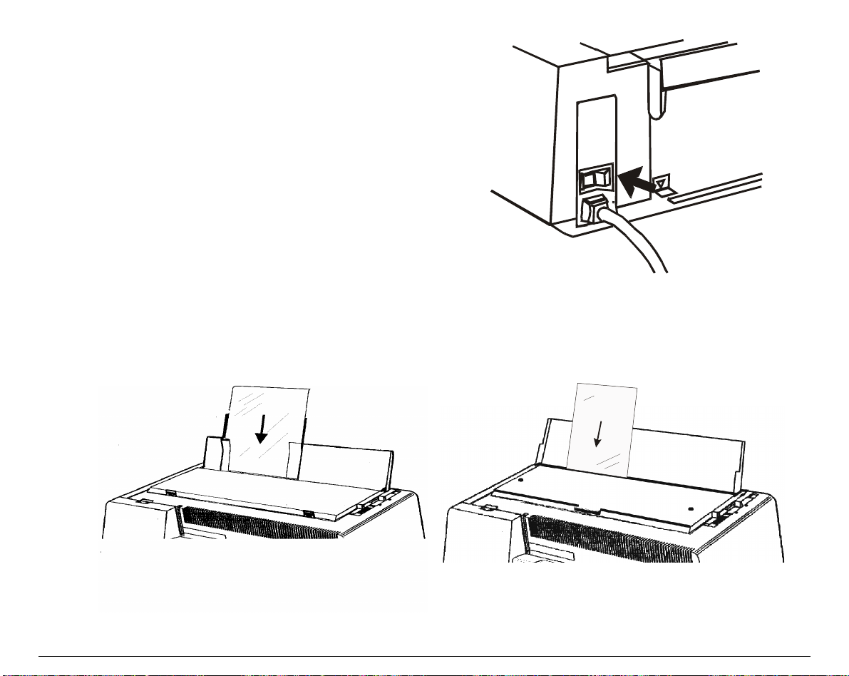
LLooaaddiinngg CCuutt SShheeeettss
1. Put the paper chute in the raised position by pulling and hooking it firmly.
• If your printer is the 4051N plus or the 4056N plus model, simply lift the paper chute that
is fixed in the printer cover.
4051/4056 plus Models 4051N/4056N plus Models
70
Page 77
If your printer is the 4051plus or the 4056
•
plus model and you wish to position the
first printing column at 25 mm from the
edge of the paper, slide the left paper
guide to the left as far as it will go, then
adjust the right paper guide according to
the paper width.
2. Move the paper thickness lever according to the type of paper:
If a cut sheet is loaded move the lever
•
towards the back of the printer.
If multicopy-chemical paper is loaded, first
•
move the lever completely towards the back
of the printer, then 1 notch towards the
front of the printer for each copy.
If carbon multicopy-paper is loaded, first
•
move the lever completely towards the back
of the printer, then 2 notches towards the
front of the printer for each copy.
Now, you can load the paper and print your first test document, see “Printing the Self Test ”. If
the pattern does not satisfy your expectation, a djust the paper thickness lever again.
When printing on multicopy paper, follow the above procedure to avoid damaging the print head
71
Page 78
3. If the printer is turned off, turn the printer on.
The display shows Load Paper, if there is no
paper in the printer. If you turn the printer on
when paper is already inserted, the display
will show Remove Paper while buzzer sounds
4 short "beeps".
The paper is ejected with a backward
movement of maximum 24 inches. If you have
not removed the paper yet, the buzzer will
sound again 4 short “beeps”. Finally the
display will show Load paper.
4. Feed the cut sheet in the slot. Press the
LOAD
or FF key. The paper will be loaded to the first
printable line. The paper is positioned at the first printable line at 1/6 inch from the top edge
of the paper. The last printable line of the sheet is positioned at 0.83 inch (21 mm) from the
bottom edge of the paper.
4051/4056 plus Models 4051N/4056N plus Models
72
Page 79
FFaannffoolldd PPaappeerr
The fanfold paper must be inserted at the rear of the printer.
IInnsseerrttiinngg FFaannffoolldd PPaappeerr
1. Put the paper chute in the raised position by lifting and hooking it firmly.
• If your printer is the 4051N plus or the 4056N plus model, lift the paper chute that is
inserted in the printer cover.
4051/4056 plus Models 4051N/4056N plus Models
73
Page 80

2. Open the tractor cover until it clicks into place.
3. Unlock the sprocket on the side of the
interface connector and, if it is not
already positioned, slide it to the right
until it stops.
74
Page 81
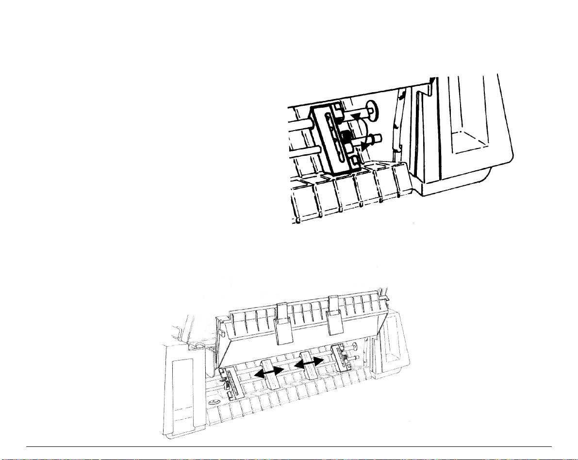
4. If you wish the first column in a particular position, the ruler under the tractor should be
helpful to position the sprocket. The distance between the ma rks on the ruler is 1/10 inch.
5. Lo ck the sprocket in place.
6. Unlock the other sprocket and position it in accordance with the paper width. Slide the
spacers evenly along the tractor bar.
75
Page 82

7. Open the sprocket covers.
8. Position the holes in the paper over one
sprocket and then over the other.
76
Page 83

9. Close the sprocket covers.
10. Adjust the two sliders on the tractor cover in alignment with the spacers and close the cover
firmly.
77
Page 84

• If your printer is the 4051 plus or the
4056 plus model, put the paper chute
in the down position by lifting it
towards the back of the printer and
pushing gently down until it stops.
Space the paper guides evenly on the
paper chute
11. Place the drive selection lever in the
fanfold position (fanfold drawing) and
make sure that Fanfold is selected by
pressing
PATH
key (
SHIFT
function) on
the operator panel.
12. If the printer is turned off, turn the printer on (see " Power Connection ” section before). The
display shows Load paper.
13. Press the
LOAD
or FF key and the paper will be positioned in front of the print head.
The paper is positioned at the first printa ble line at 1/6 inch from the top edge of the paper. If
you want to adjust the paper position, follow the instructions of the "Top of Form Adjustment "
section later. The last printable line of the last form is positioned at 0.31 inch (8 mm) from the
bottom edge of the paper
It is advisable not to print two lines before and two lines after the paper perforation.
78
Page 85

PPaarrkkiinngg FFaannffoolldd PPaappeerr
Whenever you wish to park the fanfold paper, fol low the sequence:
1. Make sure that the printer is disabled to print (Wait message is displayed and the
READY
indicator is unlit) and tear the fanfold paper that is currently loaded along the last
perforation.
2. Press the
4051/4056 plus Models 4051N/4056N plus Models
SHIFT
key and then the
PARK
key to enable the PARK function. The message
Parking paper will be displayed, the fanfold paper will move backwards up to its parking
position. The fanfold paper is still inserted into the tractors and ready to be fed as necessary.
• When the fanfold paper to park is too long, two messages will be alternatively displayed:
1. Tear-off paper
2. Remove paper
Tear the printed paper and press again the
PARK
key.
• When you need to load again the fanfold paper, make sure that the drive selecti on lever is
in fanfold position and that the paper type (PATH function) selection is Fanfold.
79
Page 86

SSwwiittcchhiinngg FFrroomm FFaannffoolldd PPaappeerr ttoo CCuutt SShheeeett
If you have been using fanfold pa per and you have not removed it, your printer allows the cut
sheet loading after performing a parking of the inserted fanfold paper (PARK function).
1. Make sure that your printer is turned on and disabl ed to print (
READY
indicator unlit). Tea r
the fanfold paper that is currently loa ded along the last perforation.
4051/4056 plus Models 4051N/4056N plus Models
2. You ca n perform the paper switching as follow s:
• Press the
SHIFT
key and then the
PATH
key. Select Manual and exit by pressing the
key. The fanfold paper moves backwards and the Enable path SS message will be
displayed, then place the drive sel ection lever in the cut sheet position. The messag e
paper
will be displayed.
SHIFT
Load
or
• Park the fanfold paper (PARK function). The Manual paper feeding will be automatically
selected when the cut sheet is loaded.
Now, your printer is ready to load cut sheet. Follow step 1 to 5 in ” Loading Cut Sheets” section.
80
Page 87

TToopp ooff FFoorrmm AAddjjuussttmmeenntt
The Top of Form Adjustment procedure allows you to adjust the position of the first printable
line and therefore it is advisable to perform it immediately after a paper loading. Turn the
printer on, if it is not, and proceed as follows:
Make sure that the printer is not printi ng. (
loaded, park it by pressing the
the FF key.
1. Press the
2. Press the ↓ key until the following message is displayed:
3. Press the → to select the function. The following message will be displayed:
4. Now go on pressing the ↓ key until the following message will be displayed
5. Press the → key to select the function. The paper is unloaded and reloaded at the TOF quote.
The current value will be printed and the display will show the following message:
PROGRAM
key. The following message will be displayed:
PARK
key. If the cut sheet has been inserted, eject it by pressing
READY
SELECT MACRO
PRINT ADJUSTMENT
BID. ALIGNMENT
TOP OF FORM
0/72 inches
0/90 inches
indicator unlit). If the fanfol d paper has b een
or
(4051/4051N plus models)
(4056/4056N plus models)
The paper is moved to the view position. While scrolling all the possible values by pressing the ↑
and ↓ keys the paper will be moved.
Pressing again the → key the displayed value is sel ected and printed, after the paper has been
taken to the correct position. Then the paper will be taken to the view position.
81
Page 88

TTeeaarr OOffff LLiinnee AAddjjuussttmmeenntt
The Tear Off Line Adjustment procedure allows you to adjust the position of the fanfold
perforation in order to tear it agai nst the printer tear off border on the cover. This procedure is
available only if the Program Setup is previously entered.
The Tear Off Line Adjustment procedure can be executed at any time during the printing.
Proceed as follows.
1. Make sure that the printer is not ena bled to print (
Wait displayed).
2. Enter the Program Setup by pressing the
displayed:
SELECT MACRO
3. Press the ↓ key until the following message will be displayed:
PRINT ADJUSTMENT
4. Press the → key to select the function. The following message will be displayed:
BID. ALIGNMENT
5. Now go on pressing the ↓ key until the following message will be displayed:
TEAR PERFO ALIGN
6. The following temporary message will be displayed :
Parking paper
Now if you press the → key the paper will be unloaded, reloaded and a form feed executed. The
paper will be taken to the corresponding tear off line.
Pressing the ↑ and ↓ keys you can scroll all the selectable values while the paper will be moved.
PROGRAM
READY
indicator unlit and the messag e
key. The following message will be
Pressing again the → key the displayed value will be selected.
82
Page 89

PPrriinntteerr MMaaiinntteennaannccee aanndd TTrroouubblleesshhoooottiinngg
CClleeaanniinngg tthhee PPrriinntteerr
Make sure that the printer has been turned off fo r at least 15 minutes bef ore any cleaning
Periodical cleaning will help to keep your printer in top condition.
• Use a neutral detergent or a water solution on a soft cloth to clean dirt and grease from the
cabinet of the printer.
• Do not use an abrasive cloth, alcohol, paint thinner, or other simila r agents, because they can
cause discoloration and scratches.
• Be careful not to damage the electronic and mechanical components.
intervention.
83
Page 90
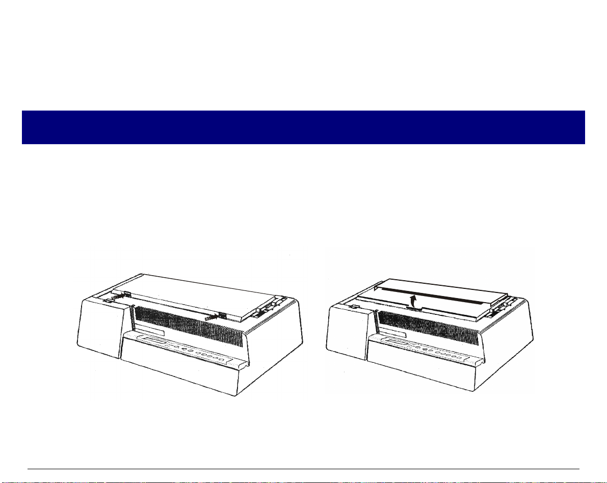
RReeppllaacciinngg tthhee RRiibbbboonn CCaarrttrriiddggee
If the printing i s fa ding , the ri bb on could b e worn or da mag ed. It is a dvisa bl e to remove the used
ribbon cartridge whil e the printer is turned off. However, your printer can be turned on during
this procedure, but do not forget that it must be disabled to print (Wait message displayed).
Make sure that the new ribbon cartridge is an original Compuprint spare part. If it is not so the
quality and reliability level declared in the product features won’t be assured.
1. Remove the printer cover by pressing simultaneously the two buttons in the front part of the
cover.
• If your printer is the 4051N plus or the 4056N plus model, do not remove but lift the
printer cover.
4051/4056 plus Models 4051N/4056N plus Models
84
Page 91
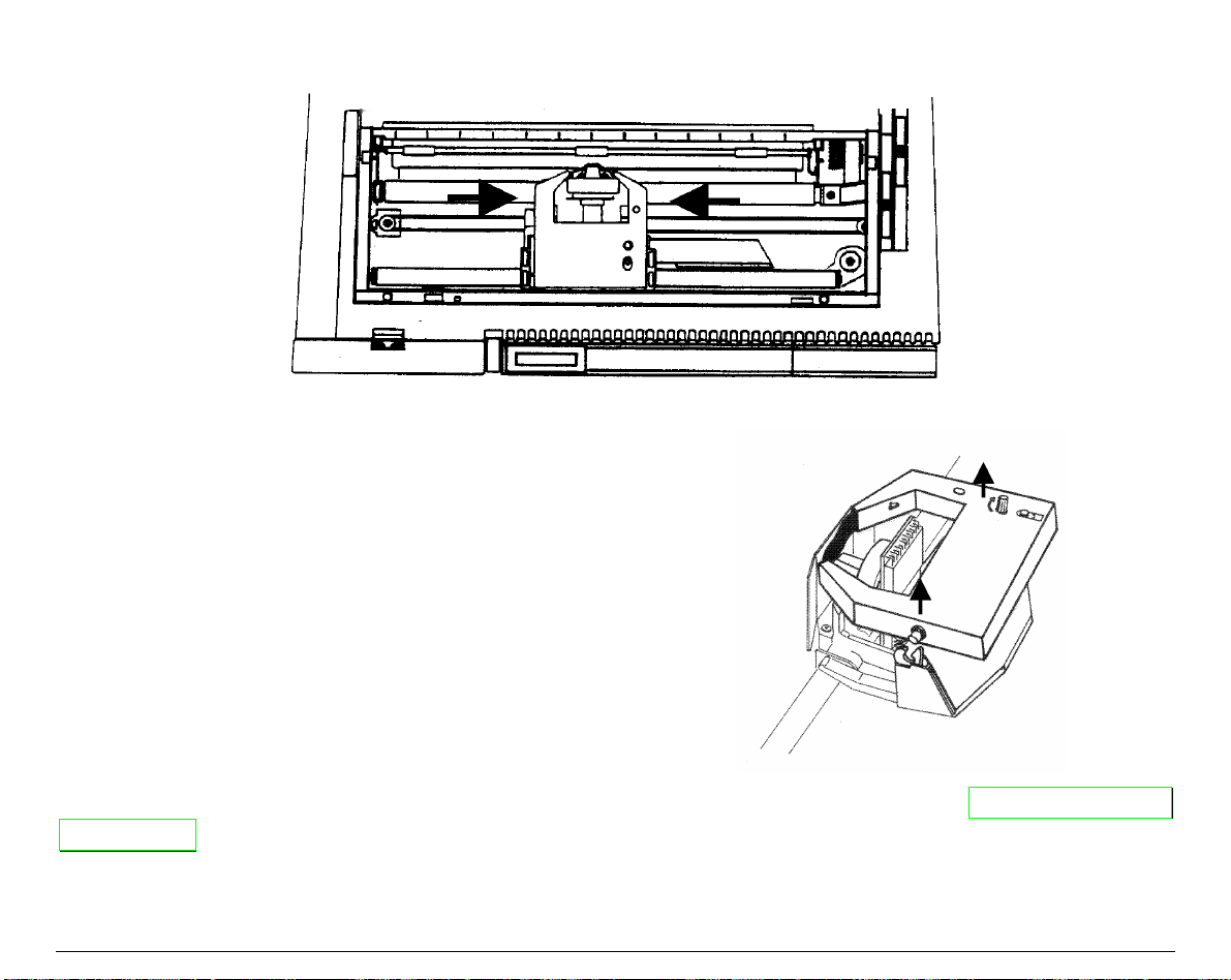
2. Move the printer carriage to the center of the printer.
3. Lift the cartridge off until the clip relea se it.
Now, you are ready to insert a new ribbon cartridge. Follow from step 2 of " Ribbon Cartridge
Installation" section.
85
Page 92

PPrriinnttiinngg tthhee SSeellff TTeesstt
It is advisable to print the self-test printout to inform you about the current printer
configuration and to check if the printer is working well.
Then, proceed as follows:
1. Keep the
following message:
The message
printed
2. Press
ON LINE
ON LINE
key pressed while you turn the printer on, the display will show the
Printing test
Printing test
key to stop printing.
will remain displayed while the following output will be
86
Page 93
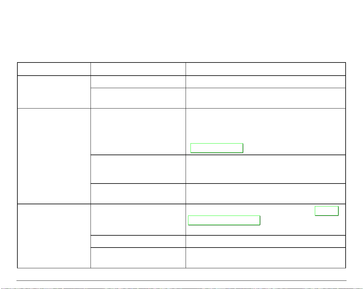
EErrrroorr HHaannddlliinngg
The following table will help you to identify and solve problems which may occur when using the
printer. If the problem is not listed, or if it is not corrected by any of the methods suggested,
contact your supplier for help.
Problem Cause Solution
Printer fails to print Wait is displayed Press
Interface cables are not
properly connected
Fanfold paper is not
advancing
Paper is not correctly aligned
The drive selection lever is
Print fading Ribbon not feeding
Ribbon worn or damaged Replace ribbon.
Print head too far from paper Pull paper thickness lever towards the back of the
Paper holes are torn Remove torn paper and replace with next good
on sprocket wheels
selected in cut sheet position.
ON LINE
Push cables firmly into sockets at both en ds.
sheet. Check the tension of the paper between left
and right sprocket wheels. If too tight, loosen, by
moving right sprocket wheels slightly to left (see
Paper Handling
“
Reload paper, ensuring that corresponding holes at
each side of paper are correctly aligned on sprocket
wheels.
Position lever in the fanfold position.
Check that ribbon is correctly loaded (see “
Cartridge Installation
knob to ensure that the ribbon is not jammed.
printer to move print head closer to paper.
key to enable printing.
” before).
”
before). Turn the tension
Ribbon
87
Page 94
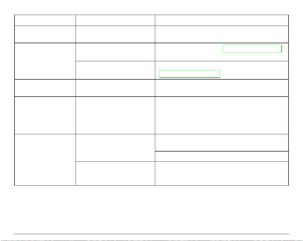
Problem Cause Solution
Dark, smudgy print Print head too close to paper Pull paper thickness lever towards the front of the
printer to move print head away from paper.
Self-test not printed
Carriage fault Press
The display shows
Remove paper
The display shows
Carriage error
ON LINE
key not pressed while
turning the printer on.
Error in the paper handling
procedure
An unrecoverable carriage
error occurred
Repeat the sequence (see “
Printing the Self Test
before).
ON LINE
Printing The Self Test
“
key and repeat the sequence (see
” before).
Try to eject the paper using ↑ and ↓ in MICRO
FEED function.
Turn the printer off. Make sure that the ribbon is
not blocked inside the cartridge by turning the
tension knob, then wait 3 seconds and turn the
printer on. If the problem is not solved, call
Technical Assistance.
Cut sheet has not been
loaded
Press
The paper chute is in down
You have not correctly
inserted the cut sheet
position
fanfold paper
Insert again cut sheet into the front paper entry slot
making sure that it reaches the roller.
LOAD
or
FF
key.
Place the paper chute in raised position and insert
again the cut sheet. Press
LOAD
(4051/4056 plus models only)
“
or FF.
88
Page 95

OOppttiioonnss
LLAANN CCoonnnneeccttiioonn
For the 4051/4056 printer models, an integrated Ethernet 10/100 Base-T interface for the
network connections is available that coexists with the serial interface.
For more information, refer to the Installation Guide you receive together the “PRINTER
SERVER ETHERNET 10/100 Mbit Multiprotocol” CD-ROM.
89
Page 96

AAuuttoommaattiicc SShheeeett FFeeeeddeerr ((44005511//44005566 pplluuss mmooddeellss oonnllyy))
This Automatic Sheet Feeder (ASF) provides fast and automatic feeding of cut sheets and
multicopy-forms on your printer. This option is quickly and easily installed onto the printer by
the operator. No tools or special equipment are necessary. Operation of the sheet feeder is
relatively simple and with proper installation and care, it will provide long and trouble-free
service. The cut sheets are contained in adjustab le pa per feed bi n and a re indi vi dual ly fed by the
feeder to the printer platen. After printing, the feeder automatically transports the sheet or
form into the output stacker of the feeder.
UUnnppaacckkiinngg AAuuttoommaattiicc SShheeeett FFeeeeddeerr
Unpack the Automatic Sheet Feeder (ASF) and check that all components are present:
User Manual
Automatic Sheet Feeder
Paper Stackers
Pa p e r S o rte r C ove r
Front Cover
90
Page 97

PPrreeppaarriinngg tthhee PPrriinntteerr
Make sure that no paper is present in the printer and that the Automatic Sheet Feeder loading
is selected via your printer operator panel (see “Configuring the Printer” section).
1. Turn the printer off.
2. Remove the printer cover by pushing down simultaneously the two buttons in the front part
of the cover and lifting it out.
91
Page 98

3. Remove the paper chute, if present, as follows:
• put it in the raised position and flex it
towards the front of the printer;
• lift the right side of the paper chute;
• unhook the left side of the paper chute.
Keep the printer cover and the paper chute in a safe place as they must be reinstalled if the ASF is
removed.
92
Page 99

4. Slide the rubber rollers (1) of the paper bail to the extreme right side. Remove the plastic
mask (2) that protects the feeding mechanism on the right side of the platen.
1
5. Put the drive selection lever in the cut
sheet position.
1
93
Page 100
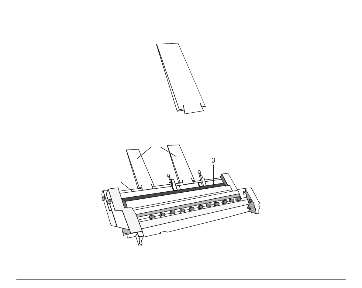
AAuuttoommaattiicc SShheeeett FFeeeeddeerr AAsssseemmbbllyy
1. Find the paper stackers.
2. Clip two paper sta ckers (1) onto the metal strip (2), placed over the paper entry slot (3), for
the input of paper.
1
2
94
 Loading...