

Page 1

Compuprint 30X6
Programmer Manual
Page 2

Contents
Commands................................................................................................................................................3
1.Index for ESC/PK ................................................3
2.Command interpretation for ESC/PK .............4
3.Other Command Sets........................................16
AR Command Set ..................................................16
OKI Command Set ................................................17
Interfaces ................................................................................................................................................19
1. The Parallel Interface..........................................19
Signals Description.................................................19
Operating Phases ...................................................20
Parallel Interface Signals ......................................20
Interface Timing.....................................................23
2. The Serial Interface .............................................23
Serial Interface Signals..........................................24
3. USB interface ........................................................24
4. Network interface.................................................25
Page 3

CCoommmmaannddss
11..IInnddeexx ffoorr EESSCC//PPKK
NO Command Function
1
ESC ( C
Set page length in defined unit
2
ESC ( U
Set unit
3
ESC C
Set page length in lines
4
ESC C NUL
Set page length in inches
5
ESC N
Set bottom margin
6
ESC O
Cancel bottom margin
7
ESC Q
Set right margin
8
ESC l
Set left margin
9
CR
CR Carriage return
10
LF
Line feed
11
FF
Form feed
12
ESC J
Advance print position vertically
13
HT
Tab horizontally
14
VT
Tab vertically
15
BS
Backspace
16
ESC 0
Select 1/8-inch line spacing
17
ESC 2
Select 1/6-inch line spacing
18
ESC 3
Set n/180-inch line spacing
19
ESC +
Set n/360-inch line spacing
20
ESC A
Set n/60-inch line spacing
21
ESC D
Set horizontal tabs
22
ESC B
Set vertical tabs
23
ESC t
Select character table
24
ESC R
Select an international character set
25
ESC %
Select user-defined set
26
ESC x
Select LQ or draft
27
ESC M
Select 12-cpi
28
ESC g
Select 15-cpi
29
ESC SP
Set character space
30
ESC 4
Select italic font
31
ESC 5
Cancel italic font
32
ESC G
Select double-strike printing
33
ESC H
Cancel double-strike printing
34
ESC q
Select character style
35
SO
Select double-width printing (one line)
36
ESC SO
Select double-width printing (one line)
Page 4
37
DC4
Cancel double-width printing (one line)
38
ESC W
Turn double-width printing on/off
39
ESC w
Turn double-height printing on/off
40
ESC U
Turn unidirectional mode on/off
41
ESC *
Select bit image
42
ESC @
Initialize printer
43
CAN
Cancel line
44
DEL
Delete last character in buffer
45
ESC -
Turn underline on/off
46
ESC E
Select bold font
47
ESC F
Cancel bold font
48
ESC P
Select 10-cpi
49
ESC p
Turn proportional mode on/off
22..CCoommmmaanndd iinntteerrpprreettaattiioonn ffoorr EESSCC//PPKK
ESC ( C Set page length in defined unit
Format
ASCII ESC ( C nL nH mL mH
Hex 1B 28 43 nL nH mL mH
Decimal 27 40 67 nL nH mL mH
Parameter range
nL = 2, nH = 0
0 < ((m
H 256) + mL) (defined unit) 22
Function
Sets the page length in the specified number of units—previously defined with the ESC( U command—according to
the following formula:
(page length) = ((mH 256) + mL) (defined unit)
ESC ( U Set unit
Format
ASCII ESC ( U nL nH m
Hex 1B 28 55 n
L nH m
Decimal 27 40 85 n
L nH m
Parameter range
nL = 1, nH = 0
m = 10, 20, 30, 40, 50, 60
Function
Sets the unit to m/3600 inch. The printer uses this unit when moving the print position,
ESC C Set page length in lines
Format
Page 5

ASCII ESC C n
Hex 1B 43 n
Decimal 27 67 n
Parameter range
1 n 127
0 < n (current line spacing) 22 inches
Function
Sets the page length to n lines in the current line spacing
ESC C NUL Set page length in inches
Format
ASCII ESC C NUL n
Hex 1B 43 00 n
Decimal 27 67 0 n
Parameter range
1 n 22
Function
Sets the page length to n inches
ESC N Set bottom margin
Format
ASCII ESC N n
Hex 1B 4E n
Decimal 27 78 n
Parameter range
0 < n 127
0 < (current line spacing) n < (page length)
Function
Sets the bottom margin on continuous paper to n lines (in the current line spacing) from the
top-of-form position on the next page.
ESC O Cancel bottom margin
Format
ASCII ESC O
Hex 1B 4F
Decimal 27 79
Function
Cancels the top and bottom margin settings
ESC Q Set right margin
Format
ASCII ESC Q n
Hex 1B 51 n
Decimal 27 81 n
Page 6

Parameter range
1 n 255
(left margin) < (current pitch) n (printable area width)
Function
Sets the right margin to n columns in the current character pitch, as measured from the leftmost
printable column
ESC l Set left margin
Format
ASCII ESC l n
Hex 1B 6C n
Decimal 27 108 n
Parameter range
1 n 255
0 (left margin) <(right margin)
Function
Sets the left margin to n columns in the current character pitch, as measured from the leftmost printable column
CR Carriage return
Format
ASCII CR
Hex 0D
Decimal 13
Function
Moves the print position to the left-margin position
LF Line feed
Format
ASCII LF
Hex 0A
Decimal 10
Function
Advances the vertical print position one line (in the currently set line spacing)
FF Form feed
Format
ASCII FF
Hex 0C
Decimal 12
Function
Advances the vertical print position on continuous paper to the top-margin position of the next page
ESC J Advance print position vertically
Format
Page 7

ASCII ESC J n
Hex 1B 4A n
Decimal 27 74 n
Parameter range
0 n 255
Function
Advances the vertical print position n/180 inch
HT Tab horizontally
Format
ASCII HT
Hex 09
Decimal 9
Function
Moves the horizontal print position to the next tab to the right of the current print position
VT Tab vertically
Format
ASCII VT
Hex 0B
Decimal 11
Function
Moves the vertical print position to the next vertical tab below the current print position
Moves the horizontal print position to the left-margin position
BS Backspace
Format
ASCII BS
Hex 08
Decimal 8
Function
Moves the print position to the left a distance equal to one character in the current character
pitch plus any additional character space.
ESC 0 Select 1/8-inch line spacing
Format
ASCII ESC 0
Hex 1B 30
Decimal 27 48
Function
Sets the line spacing to 1/8 inch
ESC 2 Select 1/6-inch line spacing
Format
Page 8

ASCII ESC 2
Hex 1B 32
Decimal 27 50
Function
Sets the line spacing to 1/6 inch
ESC 3 Set n/180-inch line spacing
Format
ASCII ESC 3 n
Hex 1B 33 n
Decimal 27 51 n
Parameter range
0 n 255
Function
Sets the line spacing to n/180 inch
ESC + Set n/360-inch line spacing
Format
ASCII ESC + n
Hex 1B 2B n
Decimal 27 43 n
Parameter range
0 n 255
Function
Sets the line spacing to n/360 inch
ESC A Set n/60-inch line spacing
Format
ASCII ESC A n
Hex 1B 41 n
Decimal 27 65 n
Parameter range
0 n 85
Function
Sets the line spacing to n/60 inch
ESC D Set horizontal tabs
Format
ASCII ESC D n1 n2 . . . nk NUL
Hex 1B 44 n
1 n2 . . . nk 00
Decimal 27 68 n
1 n2 . . . nk 0
Parameter range
0 k 32
1 n 255
Page 9

nk > n(k-1)
Function
Sets horizontal tab positions (in the current character pitch) at the columns specified by n1 to nk, as measured from the
left-margin position
ESC B Set vertical tabs
Format
ASCII ESC B n1 n2 . . . nk NUL
Hex 1B 42 n
1 n2 . . . nk 00
Decimal 27 66 n
1 n2 . . . nk 0
Parameter range
0 k 16
1 n 255
n
k > n(k-1)
Function
Sets vertical tab positions (in the current line spacing) at the lines specified by n1 to nk, as
measured from the top-margin position
ESC t Select character table
Format
ASCII ESC t n
Hex 1B 74 n
Decimal 27 116 n
Parameter range
0 n 3
Function
Selects the character table to be used for printing from among the four character tables
described below:
n = 0Character table 0
1 Character table 1
2 Character table 2
3 Character table 3
Default
table 0 Italic
table 1 PC437
table 2 User-defined characters
table 3 PC437
ESC R Select an international character set
Format
ASCII ESC R n
Hex 1B 52 n
Decimal 27 82 n
Parameter range
Page 10

0 n 13
Function
Selects the set of characters printed for specific character codes, as listed below:
n = 0 USA
1 France
2 Germany
3 United Kingdom
4 Denmark I
5 Sweden
6 Italy
7 Spain I
8 Japan (English)
9 Norway
10 Denmark II
11 Spain II
12 Latin America
ESC % Select user-defined set
Format
ASCII ESC % n
Hex 1B 25 n
Decimal 27 37 n
Parameter range
n = 0, 1
Function
Switches between normal and user-defined characters, as follows:
n = 0 Normal (ROM) characters
1 User-defined (RAM) characters
ESC x Select LQ or draft
Format
ASCII ESC x n
Hex 1B 78 n
Decimal 27 120 n
Parameter range
n = 0, 1
Function
Selects either LQ or draft printing according to the following values:
n = 0 Draft printing
1 Letter-quality printing
ESC M Select 12-cpi
Format
ASCII ESC M
Page 11

Hex 1B 4D
Decimal 27 77
Function
Selects 12-cpi character pitch
ESC g Select 15-cpi
Format
ASCII ESC g
Hex 1B 67
Decimal 27 103
Function
Selects 15-cpi character printing
ESC SP Set character space
Format
ASCII ESC SP n
Hex 1B 20 n
Decimal 27 32 n
Parameter range
0 n 127
Function
Increases the space between characters by n/180 inch in LQ mode and n/120 inch in draft mode
ESC 4 Select italic font
Format
ASCII ESC 4
Hex 1B 34
Decimal 27 52
Function
Sets the style attribute of the font to italic
ESC 5 Cancel italic font
Format
ASCII ESC 5
Hex 1B 35
Decimal 27 53
Function
Sets the style attribute of the font to normal (cancels the italic style attribute previously
selected with the ESC 4 command)
ESC G Select double-strike printing
Format
ASCII ESC G
Hex 1B 47
Page 12

Decimal 27 71
Function
Prints each dot twice, with the second slightly below the first, creating bolder characters
ESC H Cancel double-strike printing
Format
ASCII ESC H
Hex 1B 48
Decimal 27 72
Function
Cancels double-strike printing selected with the ESC G command
ESC q Select character style
Format
ASCII ESC q n
Hex 1B 71 n
Decimal 27 113 n
Parameter range
0 n 3
Function
Turns on/off outline and shadow printing, according to the parameters below:
n = 0 Turn off outline/shadow printing
1 Turn on outline printing
2 Turn on shadow printing
3 Turn on outline and shadow printing
SO Select double-width printing (one line)
Format
ASCII SO
Hex 0E
Decimal 14
Function
Doubles the width of all characters, spaces, and character spacing (set with the ESC SP
command) following this command on the same line.
ESC SO Select double-width printing (one line)
Format
ASCII ESC SO
Hex 1B 0E
Decimal 27 14
Function
Doubles the width of all characters, spaces, and character spacing (set with the ESC SP
command) following this command on the same line.
Page 13

DC4 Cancel double-width printing (one line)
Format
ASCII DC4
Hex 14
Decimal 20
Parameter range
No parameters
Function
Cancels double-width printing selected by the SO or ESC SO commands
ESC W Turn double-width printing on/off
Format
ASCII ESC W n
Hex 1B 57 n
Decimal 27 87 n
Parameter range
n = 0, 1
Function
Turns on/off double-width printing of all characters, spaces, and character spacing (set
with the ESC SP command) following this command as follows:
n = 1 Turns on double-width
0 Turns off double-width
ESC w Turn double-height printing on/off
Format
ASCII ESC w n
Hex 1B 77 n
Decimal 27 119 n
Parameter range
n = 0, 1
Function
Turns on/off double-height printing of all characters, as measured from the current baseline:
n = 1 Turns on double-width
0 Turns off double-width
ESC U Turn unidirectional mode on/off
Format
ASCII ESC U n
Hex 1B 55 n
Decimal 27 85 n
Parameter range
n = 0, 1
Function
Selects bidirectional or unidirectional printing, according to the parameters below:
Page 14

n = 0 Bidirectional printing
1 Unidirectional printing
ESC * Select bit image
Format
ASCII ESC * m nL nH d1 . . . dk
Hex 1B 2A m nL nH d1 . . . dk
Decimal 27 42 m nL nH d1 . . . dk
Parameter range
0 nL 255
0 n
H 31
m = 0, 1, 2, 3, 6, 32, 33, 38, 39, 40
Function
Prints dot-graphics in 8, 24,depending on the following parameters:
ESC @ Initialize printer
Format
ASCII ESC @
Hex 1B 40
Decimal 27 64
Function
Resets the printer to its default settings
CAN Cancel line
Format
ASCII CAN
Hex 18
Decimal 24
Function
Clears all printable characters and bit-image graphics on the current line
DEL Delete last character in buffer
Format
ASCII DEL
Hex 7F
Decimal 127
Function
Deletes the last printable character in the print buffer’s current line
ESC - Turn underline on/off
Format
ASCII ESC - n
Hex 1B 2D n
Decimal 27 45 n
Page 15

Parameter range
n = 0, 1
Function
Turns on/off printing of a line below all characters and spaces following this command:
n = 1 Turns underline on
0 Turns underline off
ESC E Select bold font
Format
ASCII ESC E
Hex 1B 45
Decimal 27 69
Function
Sets the weight attribute of the font to bold
ESC F Cancel bold font
Format
ASCII ESC F
Hex 1B 46
Decimal 27 70
Function
Sets the weight attribute of the font to normal (cancels the bold weight previously set with
the ESC E command)
ESC P Select 10-cpi
Format
ASCII ESC P
Hex 1B 50
Decimal 27 80
Function
Selects 10-cpi character pitch
ESC p Turn proportional mode on/off
Format
ASCII ESC p n
Hex 1B 70 n
Decimal 27 112 n
Parameter range
n = 0, 1
Function
Selects either proportional or fixed character spacing according to the following values:
n = 0 Returns to current fixed character pitch
1 Selects proportional spacing
Page 16
33..OOtthheerr CCoommmmaanndd SSeettss
AARR CCoommmmaanndd SSeett
NO Command Function
1
CR
Carriage return
2
ESC J n
Advance print position vertically
3
LF
Line feed
4
ESC 0
Select 1/8-inch line spacing
5
ESC + n
Set n/360-inch line spacing
6
ESC 2
Select 1/6-inch line spacing
7
ESC 3 n
Set n/180-inch line spacing
8
ESC A n
Set n/60-inch line spacing
9
ESC B n1 n2 …n k
NUL
Set vertical tabs
10
ESC C NUL n
Set page length in inches
11
ESC C n
Set page length in lines
12
ESC D n1 n2 … n
k NUL
Set horizontal tabs
13
ESC l n
Set left margin
14
ESC N n
Set bottom margin
15
ESC O
Cancel bottom margin
16
ESC Q n
Set right margin
17
ESC SP n
Set character space
18
FF
Form feed
19
HT
Tab horizontally
20
VT
Tab vertically
21
DC4
Cancel double-width printing (one line)
22
ESC - n
Turn underline on/off
23
ESC 4
Select italic font
24
ESC 5
Cancel italic font
25
ESC E
Select bold font
26
ESC F
Cancel bold font
27
ESC G
Select double-strike printing
28
ESC g
Select 15-cpi
29
ESC H
Cancel double-strike printing
30
ESC M
Select 12-cpi
31
ESC P
Select 10-cpi
32
ESC p n
Turn proportional mode on/off
33
ESC SO
Select double-width printing (one line)
34
ESC W n
Turn double-width printing on/off
35
ESC w n
Turn double-height printing on/off
36
ESC x n
Select LQ or draft
Page 17
37
SO
Select double-width printing (one line)
38
ESC R n
Select an international character set
39
ESC t n
Select character table
40
ESC % n
Select/deselect user-defined set
41
ESC * m nL nH
Select bit image
42
CAN
Cancel line
43
DEL
Delete last character in buffer
44
BS
Backspace
45
ESC @
Initialize printer
46
ESC U n
Turn unidirectional mode on/off
47
ESC X n1 n2
Set the left/right margin
48
ESC f
Set forward feeding
49
ESC v
Set reverse feeding
OOKKII CCoommmmaanndd SSeett
NO Command Function
1
DC1
Set on-line status
2
DC3
Set off-line status
3
CAN
Clear the buffer
4
ESC k
Set SHIFT JIS mode
5
ESC l
Cancel SHIFT JIS mode
6
LF
Line feed
7
ESC 6
Set the 1/6 inch line spacing
8
ESC 8
Set the 1/8 inch line spacing
9
ESC % 9 n1 n2
Set the n/120 inch line spacing
10
ESC % 5 n
Forward paper by n/120 inch
11
ESC F n1 n2
Set the page length
12
FF
Form feed
13
ESC G n1 n2
Set the perforation
14
DC4
Set vertical tab
15
VT
Tab vertically
16
CR
Carriage return
17
ESC % 4 n1 n2
Move the print head leftward
18
BS
Backspace
19
ESC % 6 n1 n2
Set the carriage return position
20
ESC % 3 n1 n2
Move the print head rightward
21
ESC ( n1 n2
Set left margin
Page 18

22
ESC ) n1 n2
Set right margin
23
ESC L
Set horizontal tab
24
HT
Tab horizontally
25
ESC N
Set Pica HS ANK character mode
26
ESC H
Set Pica HD ANK character mode
27
ESC B
Set Elite HS ANK character mode
28
ESC E
Set Elite HD ANK character mode
29
ESC % 1 n1 n2
Figure data transfer
30
ESC % 2 n1 n2
Horizontal double extended figure data transfer
31
ESC D
Set high speed printing
32
ESC I
Set high density printing
33
ESC X
Set underline printing mode
34
ESC Y
Cancel the underline printing mode
35
ESC U
Set double extended printing mode
36
ESC R
Cancel the horizontal extended mode for ANK character
37
ESC <
Cancel horizontal compress printing mode
38
ESC >
Cancel horizontal compress printing mode
39
ESC [
Set vertical extended printing mode
40
ESC ]
Cancel vertical extended printing mode
41
ESC i
Set bold printing mode
42
ESC j
Cancel bold printing mode
43
ESC % U
Set unidirectional printing mode
44
ESC % B
Set bi-directional printing mode
45
ESC m
Set repeat printing mode
46
ESC n
Cancel repeat printing mode
Page 19

IInntteerrffaacceess
This appendix provides technical information for the parallel and serial interfaces
11.. TThhee PPaarraalllleell IInntteerrffaacce
e
The parallel interface of this printer fully supports the Centronics protocol plus the specific features
requested by the EPSON and IBM printer connection in monodirectional mode and the Compatibility
and Nibbles modes in bidirectional mode, plus the negotiation phases and the device identifier (as IEEE
P1284).
The parallel interface is available on a specific 36 contact connector type AMPHENOL
57-40360-12-D56 or equivalent connector for 1284 Type B.
• Drive Capability
Up to 15 feet (5 m) on AWG26 min. wire size of twisted conductors on TTL receiver. The max.
reachable distance is conditioned by the host drive capability and by the noise level along the
interface cable path.
• Printer Connector Type
36 pins, 1284 Type B
• Cable Connector
25 pin, 1284 A Type
SSiiggnnaallss DDeessccrriippttiioonn
According to the IEEE - P1284 Standard, the pins assume different meanings and are identified by
different names depending on the actual handshaking mode as follows:
• Compatibility mode (Centronics)
This is the lower level mode provides an asynchronous, byte-wide forward (host-to-peripheral)
channel with data and status lines used according to their original definitions. The interfaces power
up in the compatibility Mode Idle phase.
• Nibble Mode
This mode provides an asynchronous, reverse (peripheral-to-host) channel, under control of the
host. In this mode, peripheral device to host data bytes are sent as two sequential, four-bit nibbles
using the four peripheral-to-host status lines. These two modes cannot be active simultaneously.
• Byte Mode
This mode provides an asynchronous, byte-wide reverse (peripheral-to host) channel based on
eight data lines of the interface for data and the control/status lines for handshaking. Byte mode is
under host control and it cannot be simultaneously active with compatibility mode.
Page 20

OOppeerraattiinngg PPhhaassees
s
The link protocol is mainly based on the following three phases:
• Negotiation Phase
This phase is activated always by the host, only when in compatibility mode, and defines:
- whether a bidirectional link protocol can be established.
- the handshaking mode as well as the communications mode to be used.
- the device identification, if supported.
• Communication Phase
This phase is based on well defined handshaking rules which depend upon the selected link mode.
• Termination Phase
This phase is initiated by the host and returns the interface to the compatibility mode.
PPaarraalllleell IInntteerrffaaccee SSiiggnnaallss
Description of the signals in monodirectional link:
Signal Name Pin N° Source Description
STROBE 1 HOST Clock signal which controls data transmission with its falling edge.
ACK 10 PRINTER Negative pulsed signal indicating that the printer has received data and
is ready to accept the next set of data. Also sent when the printer is
switched from off-line to on-line and at the end of the initialization
time. The BUSY line is always active.
DATA BIT 1
DATA BIT 2
DATA BIT 3
DATA BIT 4
DATA BIT 5
DATA BIT 6
DATA BIT 7
2
3
4
5
6
7
8
PRINTER /
HOST
Data 8 is the most significant bit. These are the data lines used by host
to transfer control code or ASCII codes.
DATA BIT 8 9
BUSY 11 PRINTER When high, this signal indicates that the printer cannot accept data
or control codes. This signal goes high during data processing, in
test and program modes, during initialization, when the buffer is
full, and when a paper jam, paper end or paper size error occurs, in
case of a power-on reset, the reception of a STROBE signal, while
the register was not yet read, or when the INIT line is still active.
Page 21

Signal Name Pin N° Source Description
PE 12 PRINTER When high, this signal indicates that printer is out of paper .
SELECT 13 PRINTER When high, this signal indicates that the printer is on-line.
AUTOFEEDX
T
14 HOST Active low level signal.
GND 16 - Logical ground level (0V).
CHASSIS
GND
17 - Frame ground.
+ 5 VDC 18 PRINTER Is the DC voltage supplied by a component that limits the driven
capability up to 100 mA.
SIGNAL GND 19-30 - Signal ground.
INIT 31 HOST Active low level signal. Indicates, that the printer is initializing. The
BUSY signal is forced high.
ERROR 32 PRINTER When low, this signal indicates that the printer is off-line, there is an
off-line request from the operator panel, or the printer is in an error
state .
+5V 35 PRINTER Pulled up to signal.
SELECTIN 36 HOST Active low level signal. Enables the printer.
Page 22

The pins 1 to 14 of the printer are connected to the pins with the same number of the parallel port of the host.
The pins 19 to 30 of the printer are connected to the pins 18 to 25 of the parallel port of the host.
The pins 31, 32 and 36 of the printer are connected respectively to the pins 16, 15 and 17 of the parallel port of the host.
1284 Mode signal names are shown with their Compatibility mode (Centronics) names in parenthesis ( ) for the bidirectional
link.
Signal Name Pin N°
for Signal Wire
Pin N°
for Return Wire
Source
HostClk (nStrobe) 1 19 HOST
AD1 (Data 1)
AD2 (Data 2)
AD3 (Data 3)
AD4 (Data 4)
AD5 (Data 5)
AD6 (Data 6)
AD7 (Data 7)
AD8 (Data 8)
2
3
4
5
6
7
8
9
20
21
22
23
24
25
26
27
HOST in Compatibility mode and
negotiation phase.
NOT USED in Nibble mode.
BIDIRECTIONAL in Byte mode.
PrtClk (nAck) 10 28 PRINTER
PrtBusy (Busy) 11 29 PRINTER
AckDataReq (PError) 12 28 PRINTER
Xflag (Select) 13 28 PRINTER
HostBusy (nAutofd) 14 30 HOST
Peripheral Logic High (+ 5V) 18 PRINTER
n.a. (nInit) 31 30 HOST
nDataAvail (NFault) 32 29 PRINTER
1284 Active (NSelectIn) 36 30
Common Logic Ground 16 and Return Wires
Chassis Ground 17
Page 23
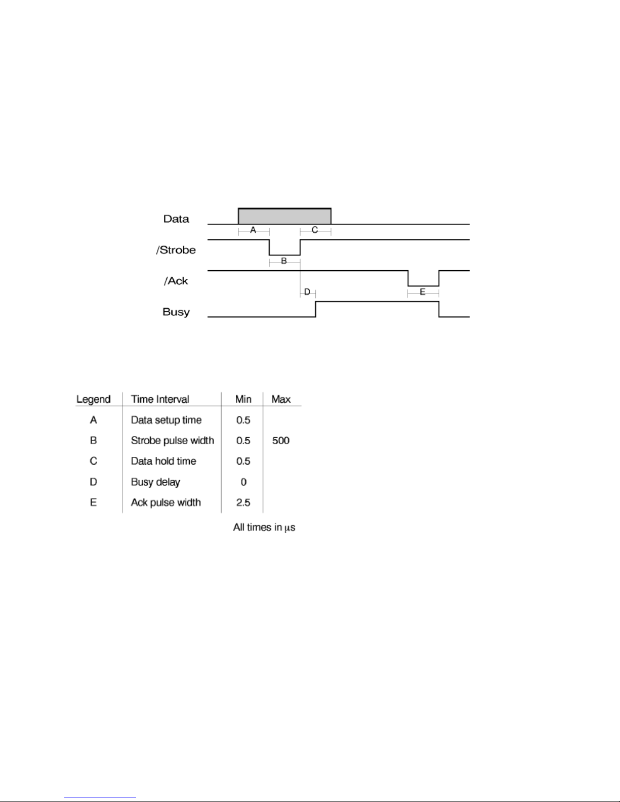
IInntteerrffaaccee TTiimmiinngg
Timing and Handshaking depend upon the connection mode.
Mode Centronics:
Our Centronics mode supports the BUSY-WHILE-STROBE busy signal timing and
ACK-WHILE-BUSY as BUSY-ACK relationship.
22.. TThhee SSeerriiaall IInntteerrffaaccee
This printer provides the RS-232/C serial interfaces. The interface mode is selected via EDS menu.
• Transmission Type
Data is sent and received in start/stop (asynchronous) transmission.
• Character Format
Each character is transmitted in the following format:
1 START BIT + 8 DATA BITS + 1 PARITY BIT + 1 STOP BIT
Page 24

The least significant bit of the data bits is sent first after the start bit. The number of data bits is
selected via menu. The parity bit, when present, follows the data bits. The start bit is a logical "0"
and the stop bit is a logical "1". The start and stop bits are used as character framing bits.
• Printer Connector
Male DB9 .
• Drive Capability
Max. 50 feet (15 m) for all supported data rates.
SSeerriiaall IInntteerrffaaccee SSiiggnnaallss
The following table lists the RS-232/C serial interface signals used:
Pin
Number
Description
Signal
Name
1
Not Connected
5V Power Supply if
necessary
2 Receive Data RXD
3 Transmit Data TXD
4 Data Terminal Ready DTR
5 Signal Ground GND
6 Data Set Ready DSR
33.. UUSSBB iinntteerrffaaccee
USB interface accords with USB 1.1 criterion.
Cable connector:
B Type
The following table lists the USB interface signals used:
USB Pin Description
1 USB 5V Power Supply
2 USB D-
3 USB D+
4 USB GND
Page 25

44.. NNeettwwoorrkk iinntteerrffaaccee
Cable connector:
8pin, RJ45
The following table lists the network interface signals used:
PPiinn NNaammee DDeessccrriippttiioonn
11
TTXX++ TTrraanncceeiivvee DDaattaa++
22
TTXX-- TTrraanncceeiivvee DDaattaa--
33
RRXX++ RReecceeiivvee DDaattaa++
44
nn//cc NNoott ccoonnnneecctteedd
55
nn//cc NNoott ccoonnnneecctteedd
66
RRXX-- RReecceeiivvee DDaattaa--
77
nn//cc NNoott ccoonnnneecctteedd
88
nn//cc NNoott ccoonnnneecctteedd
 Loading...