

Page 1
Uss
U
Rev. 01
78413012-001 Sett. 08
err
e
M
M
a
a
n
n
u
u
all
a
Page 2

Compuprint Products Information
Thanks for choosing the 10300 printer.
Your printer is a reliable working equipment that will be very useful in your daily job.
Our printers have been designed to be compact and respectful of the work environment. They offer
a wide range of features and multiple functions that confirm the high technological level reached
by the Sferal printers with Compuprint brand.
To maintain these printing performances unchanged in the long run, Sferal wwt has developed
specific Compuprint branded consumables for each printer type (for example: ribbon cartridges
for dot matrix printers, toner and OPC cartridges for laser printers, bubble ink jet cartridges for
inkjet printers) that assure an excellent operation with high printing quality level reliability.
Sferal wwt recommends to use only its original Compuprint branded consumables with original
packaging (identified by its holographic label). In this way, a proper use of the printer at quality
level stated in the product characteristics can be assured. All typical usage problems related to not
certified consumables may be avoided, such as an overall quality print level degradation and,
often, the reduction of the product life due to the fact that the proper working conditions for the
print heads, OPC cartridge and other printer parts are not assured.
Moreover, Sferal does not only certify its consumables in terms of working conditions but also
carefully controls their compliance with the international standard rules concerning:
• no cancerous materials;
• no flammability of the plastic materials;
• other standards
Sferal advises the customers not to use products for which the compliance to this safety rules are
not warranted. Finally seek your dealer or contact a Sferal office and be sure that are provided
you the original Compuprint branded consumables.
Compuprint Products Information
Page 3

FFFFCC NNootteess
This equipment has been tested and found to comply with the limits for a Class A digital device, pursuant to Part 15 of
the FCC Rules. These limits are designed to provide reasonable protection against harmful interference when the
equipment is operated in a commercial environment. This equipment generates, uses, and can radiate radio frequency
energy and, if not installed and used in accordance with the instruction manual, may cause harmful interference to
radio communications. Operation of this equipment in a residential area is likely to cause harmful interference in
which case the user will be required to correct the interference at his own expense. Properly shielded and grounded
cables and connectors must be used in order to meet FCC emission limits. SFERAL WWT is not responsible for any
radio or television interference caused by using other than recommended cables and connectors or by unauthorized
changes or modifications to this equipment. Unauthorized changes or modifications could void the user’s authority to
operate the equipment. This device complies with Part 15 of the FCC Rules. Operation is subject to the following two
conditions: (1) this device may not cause harmful interference, and (2) this device must accept any interference
received, including interference that may cause undesired operation.
EEuurrooppeeaann UUnniioonn ((EEUU)) CCoonnffoorrmmiittyy SSttaatteemmeenntt
SFERAL WWT declares that this product is in compliance with the essential requirements and other relevant
provisions of Directive 2006/95/EC, 2004/108/EC.
Per the applicable requirements of EU directive 98/37/EC (“machines”) sound pressure of the above product (measured
according to EN27779) does not exceed 70dBA.
This product has been tested and found to comply with the limits for Class A Information Technology Equipment
according to European standard EN 55022. The limits for Class A equipment were derived for commercial and
industrial environments to provide reasonable protection against interference with licensed communication devices.
Important This is a Class A product. In a domestic environment this product may cause radio interference in which
case the user may be required to take adequate measures.
Properly shielded and grounded cables and connectors must be used in order to reduce the potential for causing
interference to radio and TV communications and to other electrical or electronic equipment. SFERAL WWT cannot
accept responsibility for any interference caused by using other than recommended cables and connectors.
IInndduussttrryy CCaannaaddaa CCoommpplliiaannccee SSttaatteemmeenntt
This Class A digital apparatus complies with Canadian ICES-003.
Cet appareil numérique de la classe A est conform à la norme NMB-003 du Canada.
SSttaatteemmeenntt ffoorr CCIISSPPRR 2222 EEddiittiioonn 22 CCoommpplliiaannccee
Attention: This is a Class A product. In a domestic environment this product may cause radio interference in which
case the user may be required to take adequate measures.
Page 4

TTaabbllee ooff CCoonntteenntts
Compuprint Products Information ....................... ii
FFC Notes .............................................................. iii
Canadian D.O.C. Radio Interference Regulation iii
EEC Regulations ................................................... iii
Table of Contents .................................................. iv
Getting to Know Your Printer ............................... 1
Printer Features .................................................................. 1
Unpacking Your Printer ..................................................... 2
Removal of the Shipment Locks ........................................ 6
Connecting the Ground Cable ........................................... 8
Printer Parts ........................................................................ 9
Front View ....................................................................... 9
Rear View ...................................................................... 10
Left Side View ............................................................... 11
Inside View .................................................................... 11
Setting Up Your Printer ....................................... 12
Choosing a Suitable Location .......................................... 12
Ribbon Cartridge Installation ..................................... 13
Front2 Push Tractor Installation .................................... 18
Removing the Front2 Push Tractor ............................ 21
Host Computer Connection .............................................. 22
Software Driver Selection ................................................ 24
Power Connection ............................................................. 25
Selecting the Display Language ......................... 27
Configuring the Printer ........................................ 28
Operator Panel Presentation ........................................... 28
Display Messages ......................................................... 29
Indicators ....................................................................... 34
Function Keys ............................................................... 35
Printer Setups ................................................................... 40
Entering the Printer Setups ........................................ 40
Moving within the Printer Setups .............................. 40
s
Leaving the Printer Setups ......................................... 41
Power-On Configuration .................................................. 42
Entering the Power-On Configuration ....................... 42
Program Setup .................................................................. 80
Entering the Program Setup ....................................... 80
ANSI Emulation ............................................................. 105
How to Select the Paper Path ........................................ 116
How to Use the Tear-Off Function ................................ 117
Selection of the Paper Size ........................................ 117
Adjusting the Tear-Off Position ................................ 118
Selection of the Tear-Off Mode .................................. 119
How to Lock/Unlock the Printer Setups ....................... 120
How to Handle the Paper Parking ................................ 121
Paper Handling................................................... 126
Paper Specifications ........................................................ 126
Fanfold Paper ............................................................. 126
Fanfold Paper Loading ................................................... 127
Loading Paper Using the Front1 Push Tractor ...... 127
Loading Paper Using the Front2 Tractor ................ 137
Printer Maintenance and Troubleshooting ..... 142
Cleaning the Printer ....................................................... 142
Replacing the Ribbon Cartridge .................................... 143
Printing the Self Test ..................................................... 145
Error Handling ................................................................ 146
Repacking the Printer for Shipment ............................. 149
Options ............................................................... 153
The Controller Board ...................................................... 153
Front2 Push Tractor ....................................................... 153
Printer Cabinet ............................................................... 153
Installing the Controller Board ..................................... 154
Printer Specifications ........................................ 158
Page 5

GGeettttiinngg ttoo KKnnooww YYoouurr PPrriinntteerr
PPrriinntteerr FFeeaattuurreess
• 24 Needle Print Head
• 136 columns @10 cpi
• High Speed Draft printing at 1300 cps, Draft printing at 950 cps and LQ printing at 133 cps
• IBM Proprinter XL24/XL24 AGM, Personal Printer 2391+, EPSON LQ Series and ANSI X3.64
emulations
• Multiple copies (1 original and 7 copies)
• Automatic paper path selection
• Easy operability via operator panel setup and S/W commands
• Use of all specific features by means of the Specific Software Driver which is applicable to the most
popular S/W Packages
• Plug & Play capability for Windows 95/98/2000/XP/NT4.0/Millennium ®/Vista
• Bi-directional IEEE 1284 parallel interface, standard serial RS-232/C interface and USB interface
• Ethernet 10/100 Base-T interface option that coexists with the parallel interface
• Optional second Push Tractor and Printer Cabinet.
1
Page 6
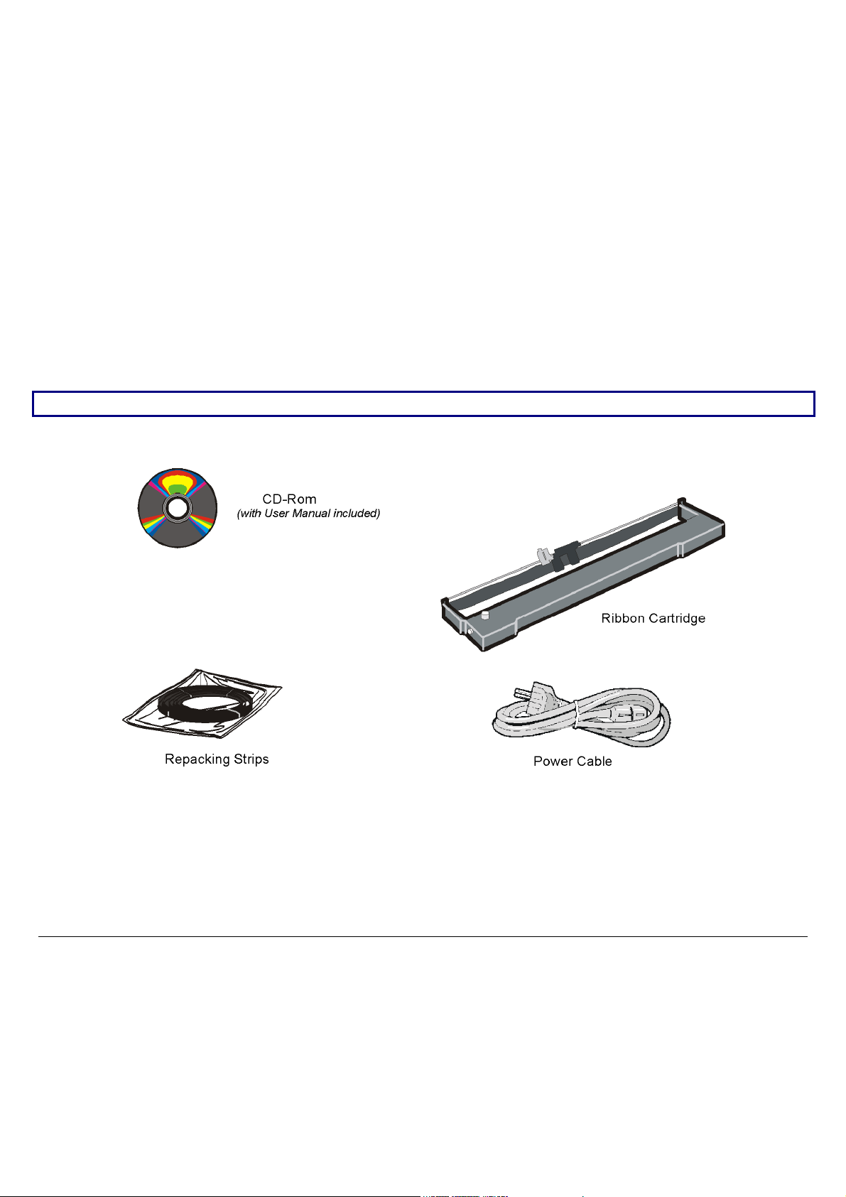
UUnnppaacckkiinngg YYoouurr PPrriinntteerr
The following items are included in the box:
Notify any damage to your supplier.
2
Page 7
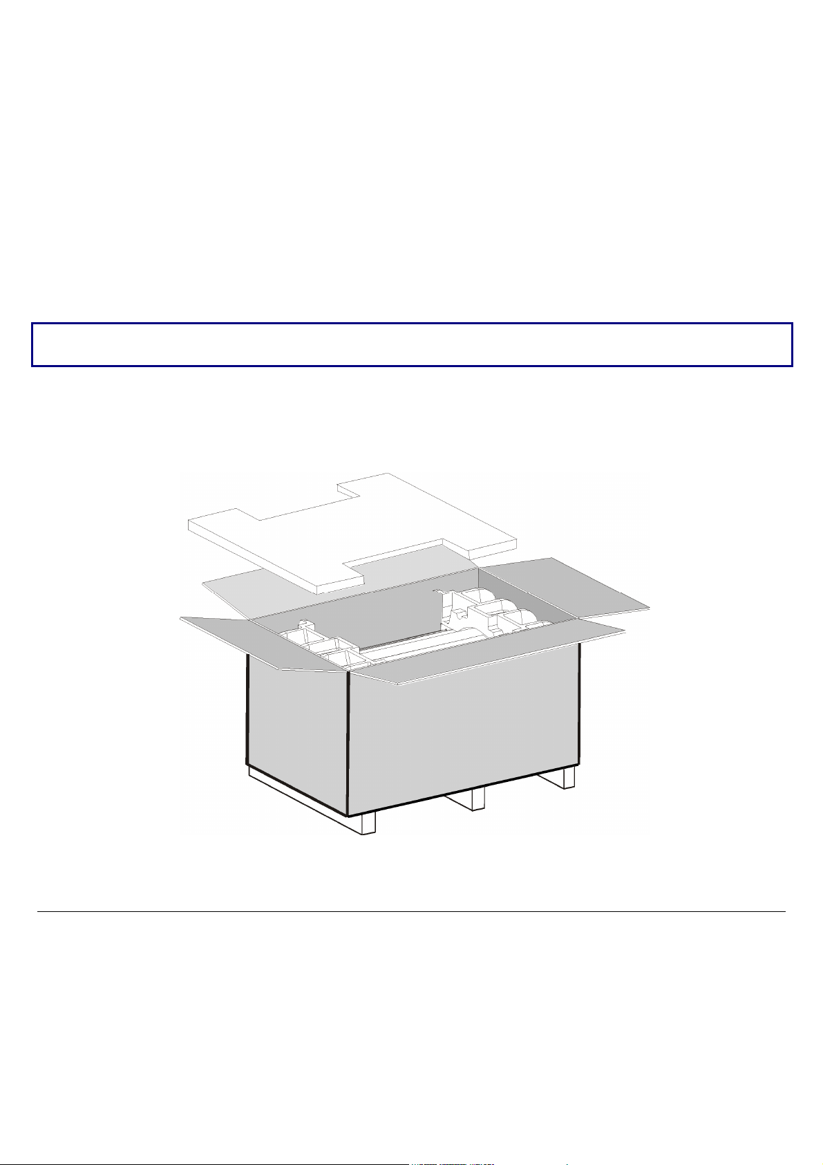
To unpack the printer proceed as follows:
Keep the packing material in a safe place. It must be used if you need to repack the printer for
shipment.
1. Bring the printer box near the final printer location.
2. Cut the packing ribbons and remove the plastic angles.
3. Remove the polystyrene panel out of the packing box.
3
Page 8
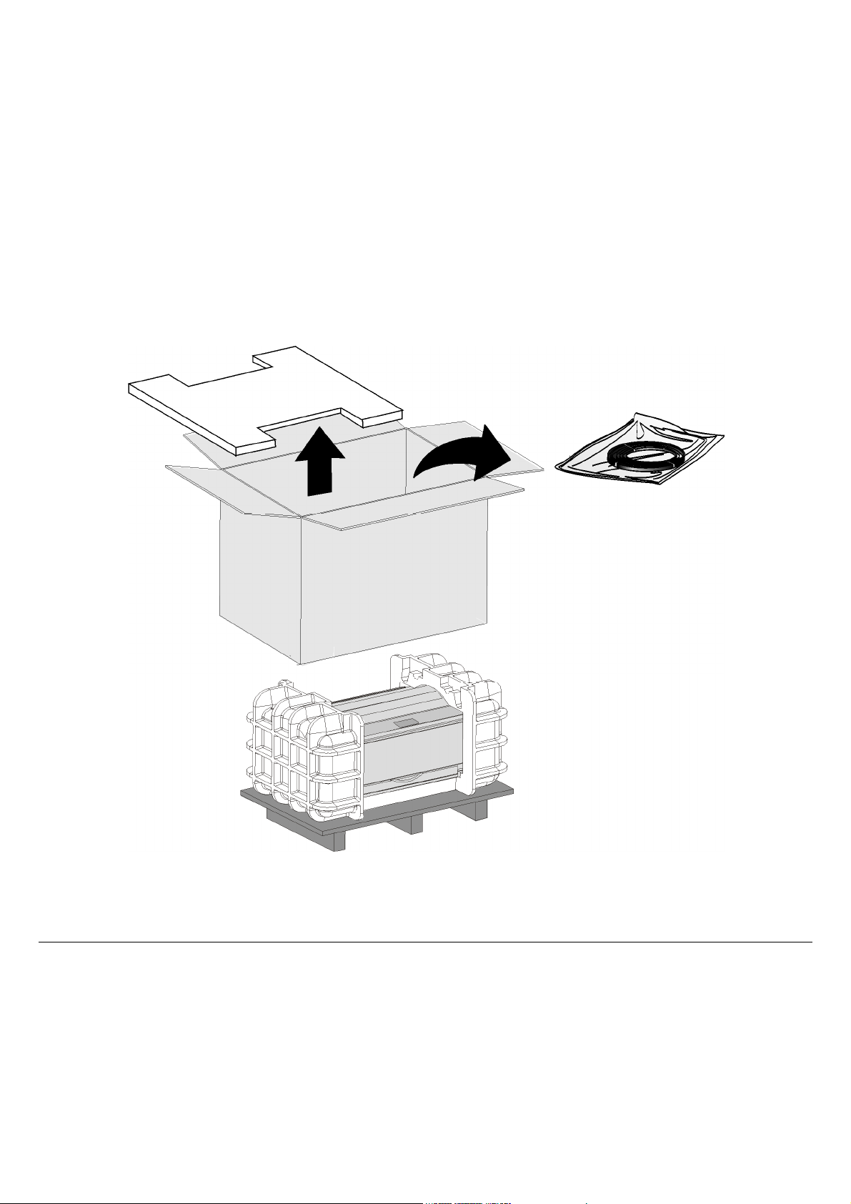
4. Remove the accessories out of the packing box and slide the packing box off the printer.
4
Page 9
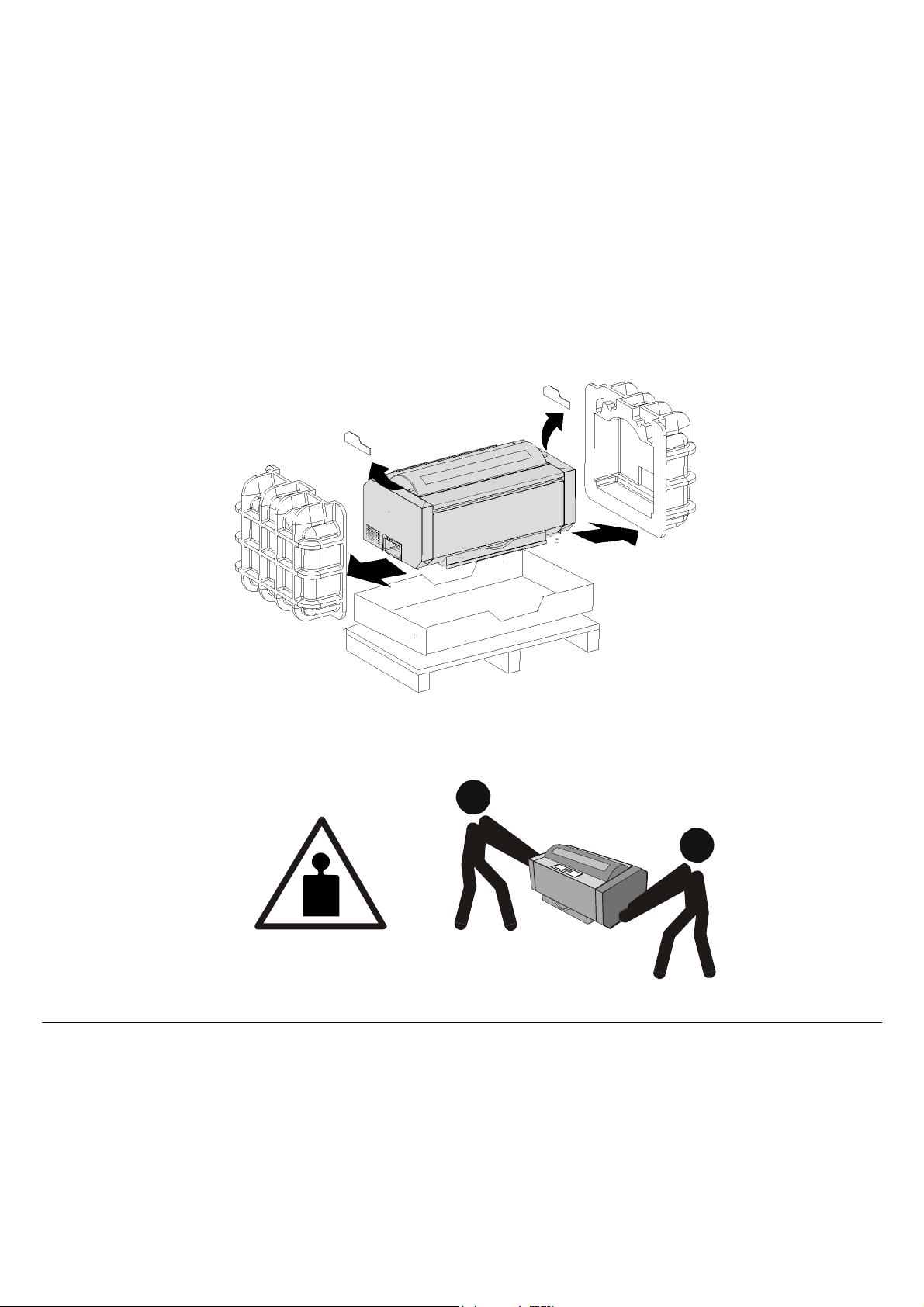
5. With the help of another person, remove the two foam shells on either side of the printer, the
plastic bag covering the printer and the two carton strips.
6. With the help of another person, move the printer to its final position:
• onto the printer cabinet (optional);
• onto a stable surface, i.e. a table.
33 Kg / 73 Lbs
5
Page 10
s
RReemmoovvaall ooff tthhee SShhiippmmeenntt LLoocckks
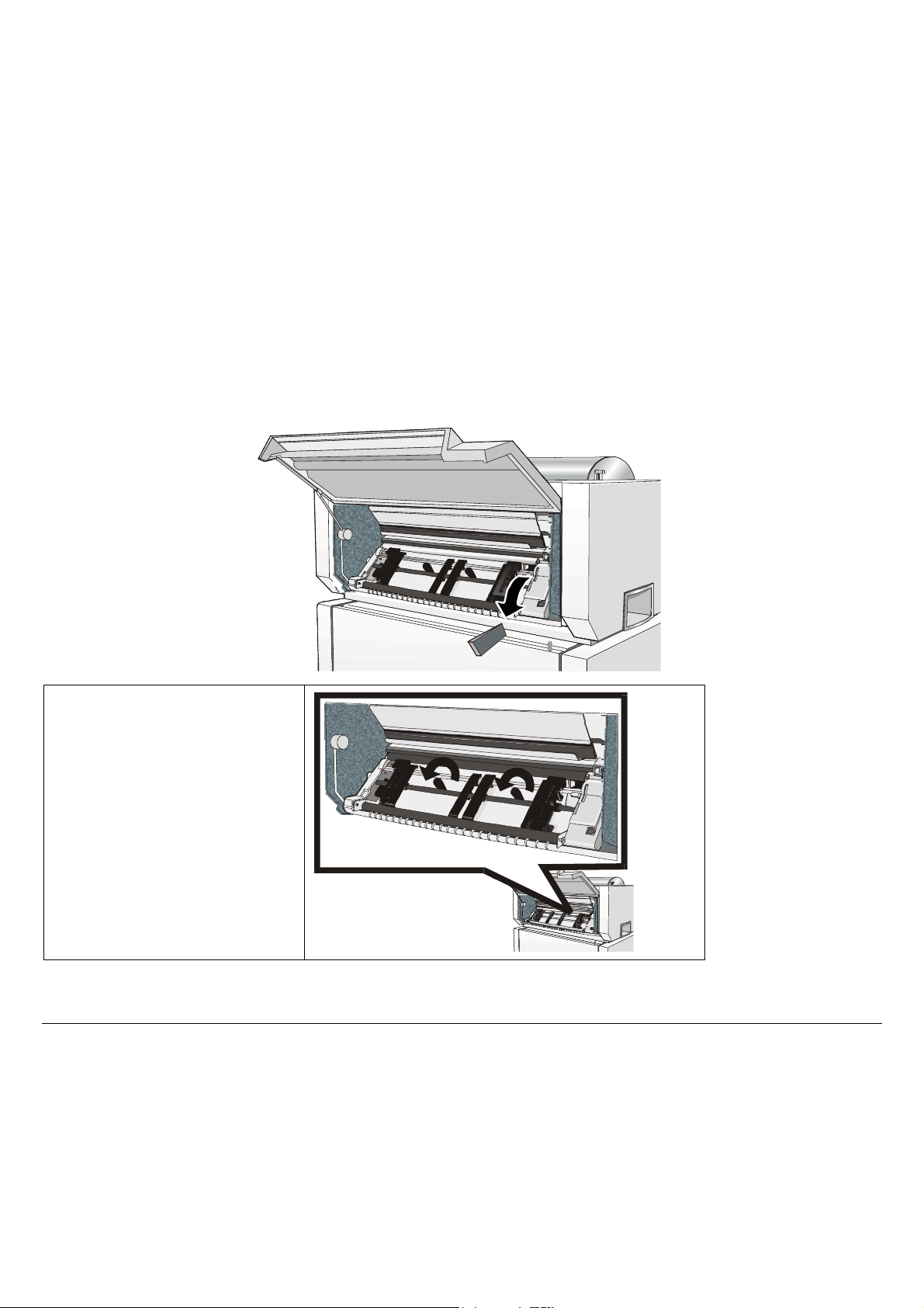
1. Open the tractor area cover and make sure that you remove the shipment lock from the
printer.
2. Unscrew the two fixing
screws.
6
Page 11
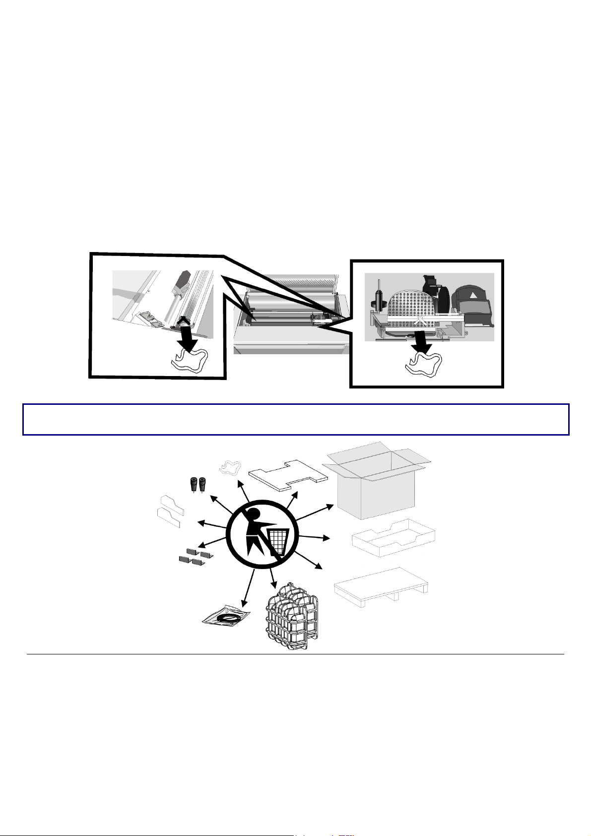
3. Open the upper printer cover and remove the fixing strip from the print head and from the
bail (two strips).
Keep all the packing material, together with the repacking kit, in a safe place. Repack the printer in
it original packaging if you need to ship or transport it.
7
Page 12
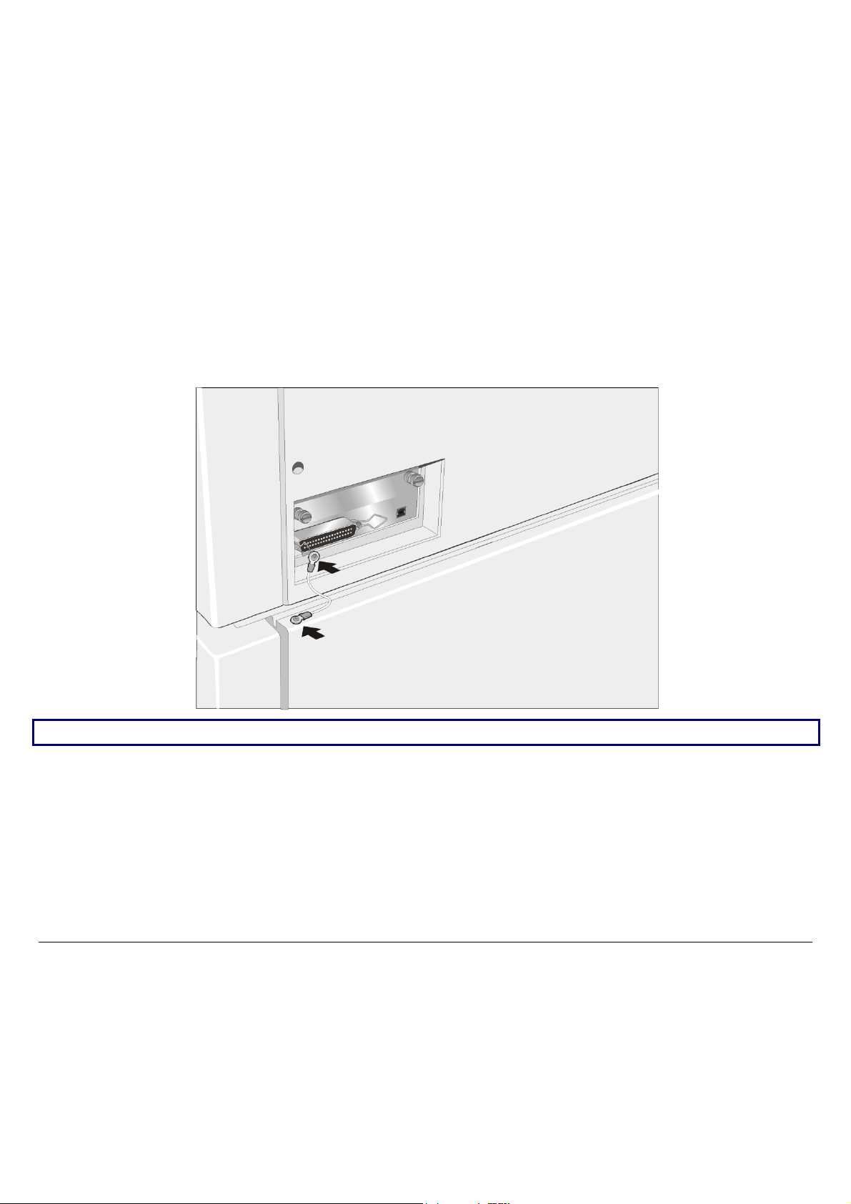
CCoonnnneeccttiinngg tthhee GGrroouunndd CCaabbllee
For the printer model with the cabinet option, connect the ground cable in the interface area on
the rear side of the printer cabinet.
If the printer is installed on a table, it is not necessary to connect the ground cable.
8
Page 13
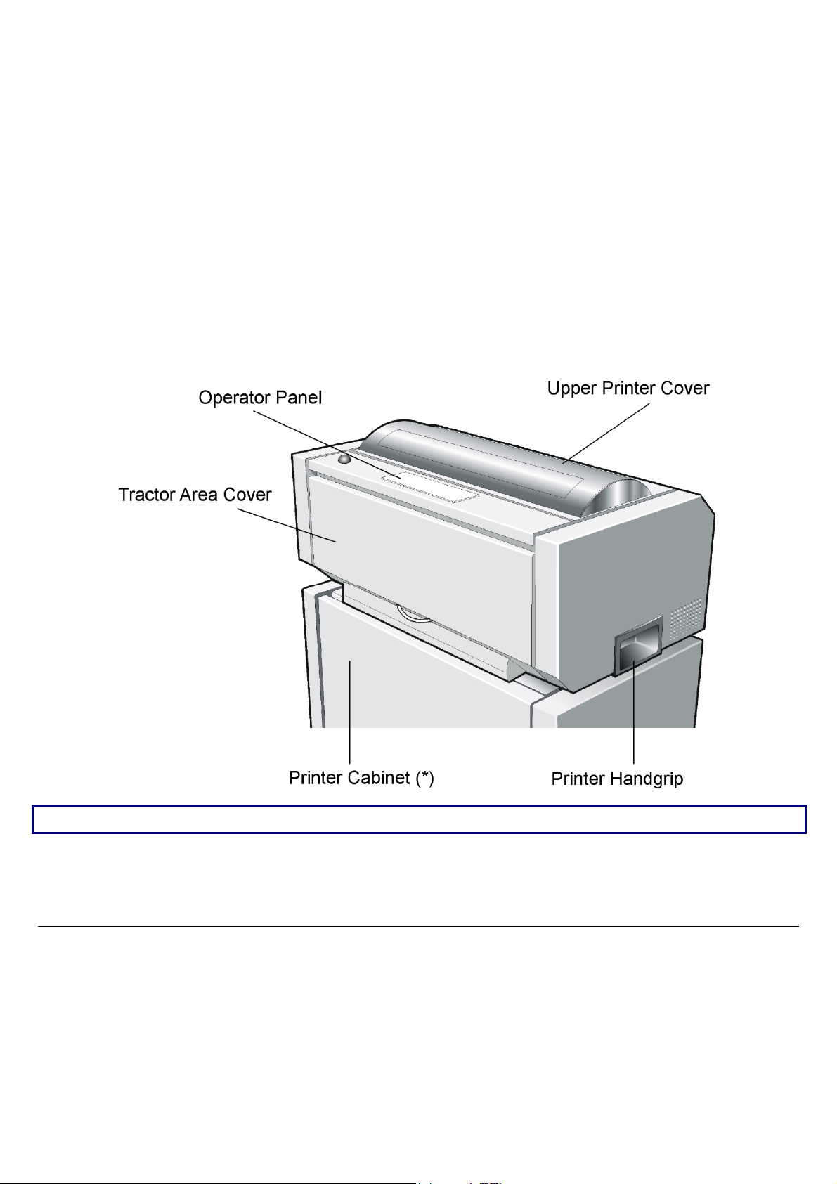
PPrriinntteerr PPaarrttss
FFrroonntt VViieeww
(*) The printer cabinet is available as an option.
9
Page 14
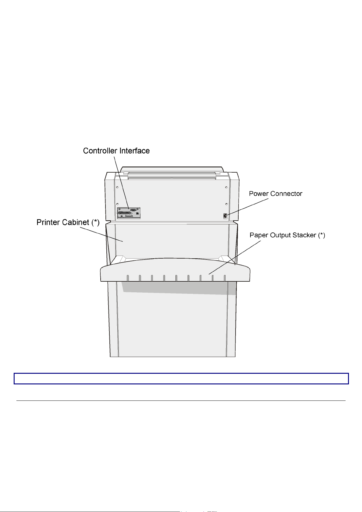
RReeaarr VViieeww
(*) The printer cabinet is available as an option.
10
Page 15
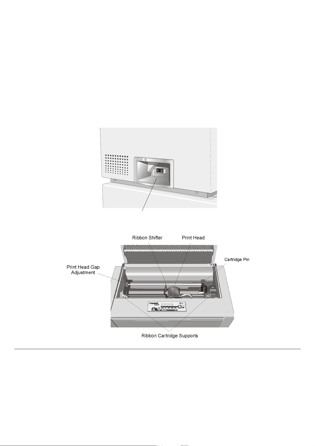
LLeefftt SSiiddee VViieeww
h
IInnssiiddee VViieeww
Power Switc
11
Page 16
SSeettttiinngg UUpp YYoouurr PPrriinntteerr
CChhoooossiinngg aa SSuuiittaabbllee LLooccaattiioonn
Consider the following points when you choose the location for your printer:
• The distance between the printer and the host computer must not exceed the length of the
interface cable;
• The location must be sturdy, horizontal and stable;
• Your printer must not be exposed to direct sunlight, extreme heat, cold, dust or humidity (see
"Printer Specifications" later);
• You need a power outlet compatible with the plug of the printer's power cord;
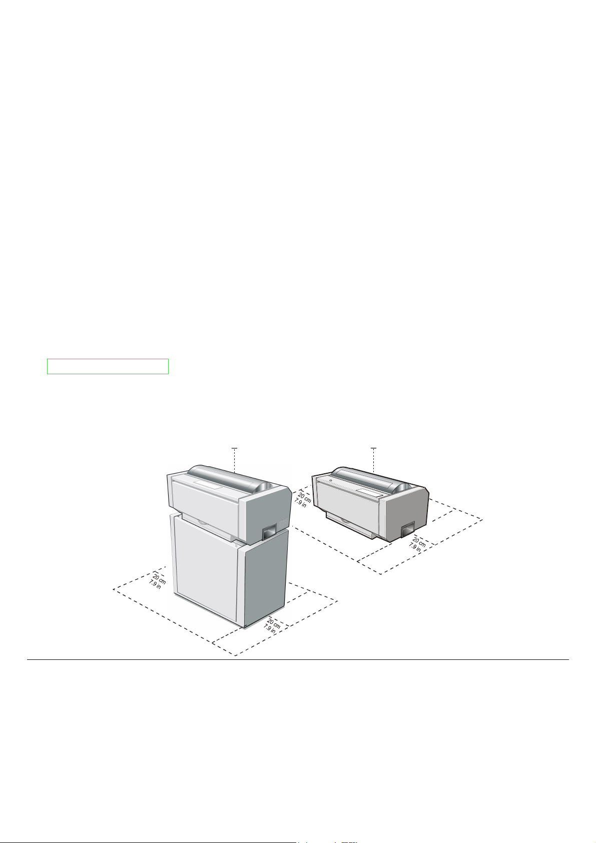
Additionally, you must make sure that when you install the printer in the selected location,
there are sufficient clearances on all sides for easy operation. The required space is shown in the
figure:
80 cm
31.5 in.
80 cm
31.5 in.
m
c
0
n
0
i
1
.4
9
3
0 cm
n
0
1
.4 i
9
3
m
0 c
n
0
i
1
.4
39
m
c
0
n
0
i
1
.4
9
3
12
Page 17
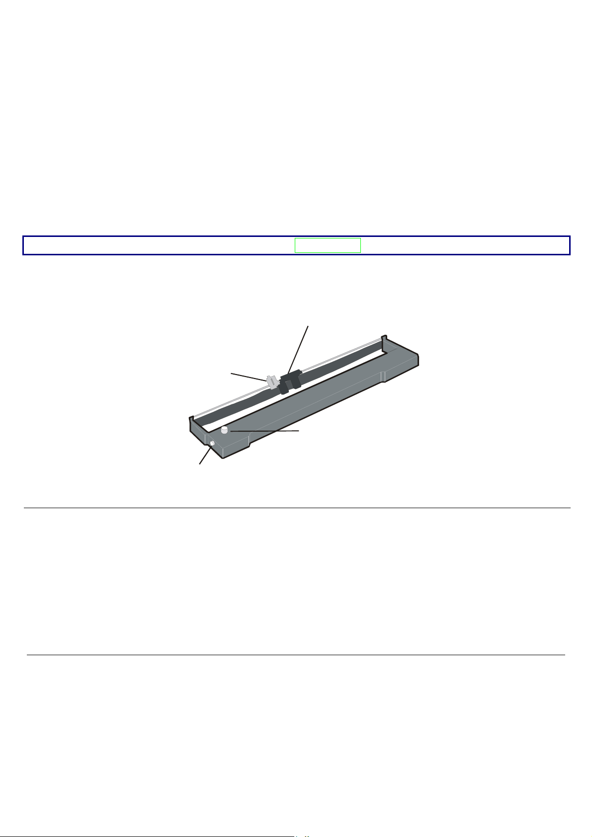
RRiibbbboonn CCaarrttrriiddggee IInnssttaallllaattiioonn
r
Make sure that you are using only Compuprint original consumables.
1. Make sure that the printer is turned off.
2. Find the ribbon cartridge among the accessories
Paper Bail
Ribbon Shifter Holde
Cartridge Pin
Tension Knob
13
Page 18
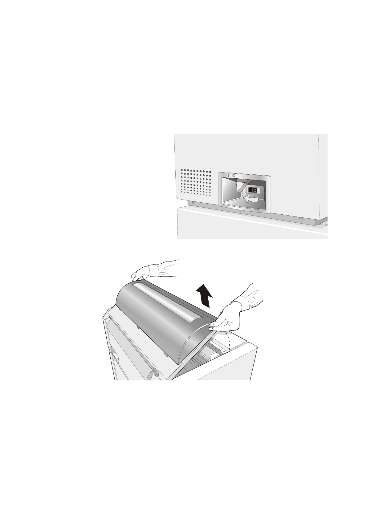
3. Turn the printer on and wait for
printer initialization. Then press
the ON LINE key to put the
printer in OFF-LINE mode (check
ON LINE indicator unlit).
4. Open the top cover using the handles on the front side of the covers.
14
Page 19
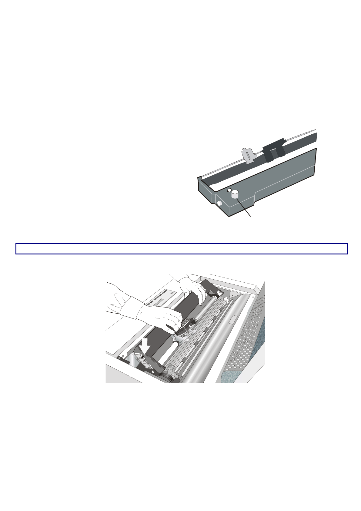
5. Before installing the ribbon cartridge
turn the ribbon-winding knob in the
arrow direction (located on the cartridge)
to take up slack in the ribbon.
Ribbon Winding Knob
To avoid damage to the ribbon, do not turn the winding knob in the wrong direction.
6. Align the right and left cartridge pins with the printer locking points.
15
Page 20
7. Slide and insert the ribbon guide between the print head and the ribbon guide mask holding it
perpendicular to the print head.
Make sure that the ribbon is inserted correctly between the print head and the print head mask.
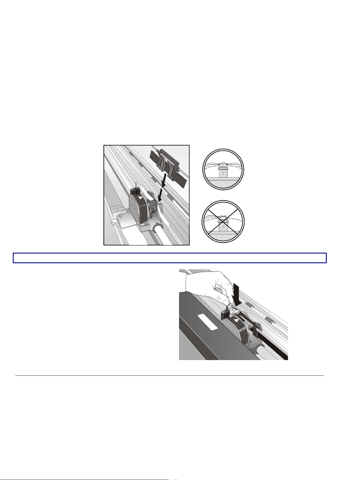
8. Insert the shifter holder onto the
ribbon shifter as shown in the
following figure.
16
Page 21
9. Turn again the ribbon-winding knob in the arrow direction (located on the cartridge) to take
up slack in the ribbon.
10. Push the cartridge down gently until it clips into place at locking points.
11. Turn the ribbon-winding knob again in the direction of the arrow to take up slack in the ribbon.
12. To ensure that the ribbon guide runs freely along the ribbon, manually move the print carriage
horizontally.
If the used ribbon cartridge needs to be replaced, see "Replacing The Ribbon Cartridge", later in this
manual.
17
Page 22
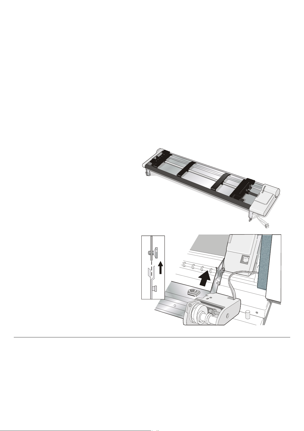
FFrroonntt22 PPuusshh TTrraaccttoorr IInnssttaallllaattiioonn
An additional front push tractor may be installed on the printer. This Front2 push tractor unit is
available as an option for the printer model. The Front2 push tractor must be installed on the
Front1 push tractor.
1. Find the Front2 push tractor among
the accessories.
2. Align the hooks on both sides of the
Front 2 tractor with the pins on the
Front 1 push tractor.
18
Page 23
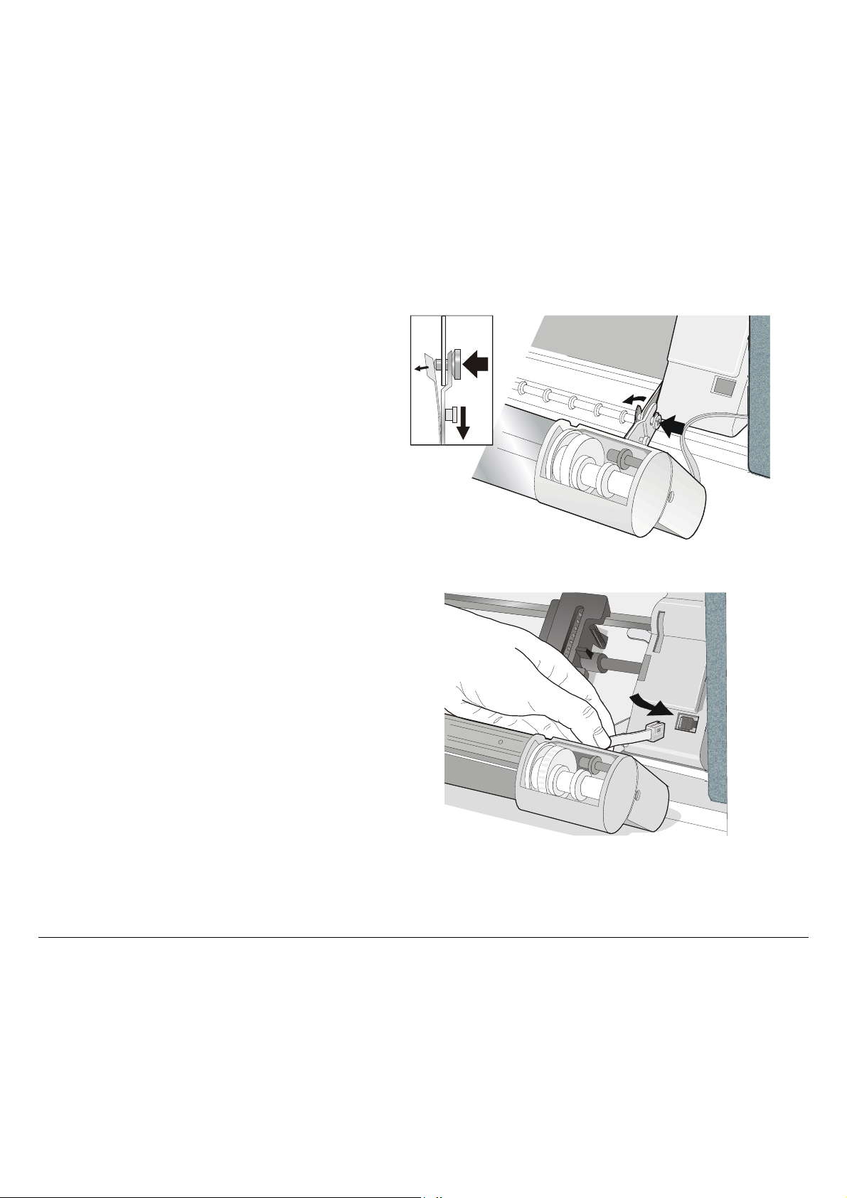
3. Push the Front 2 tractor until it is
fully engaged.
4. Insert the connector cable in the
electrical connector located in the
lower push tractor.
19
Page 24
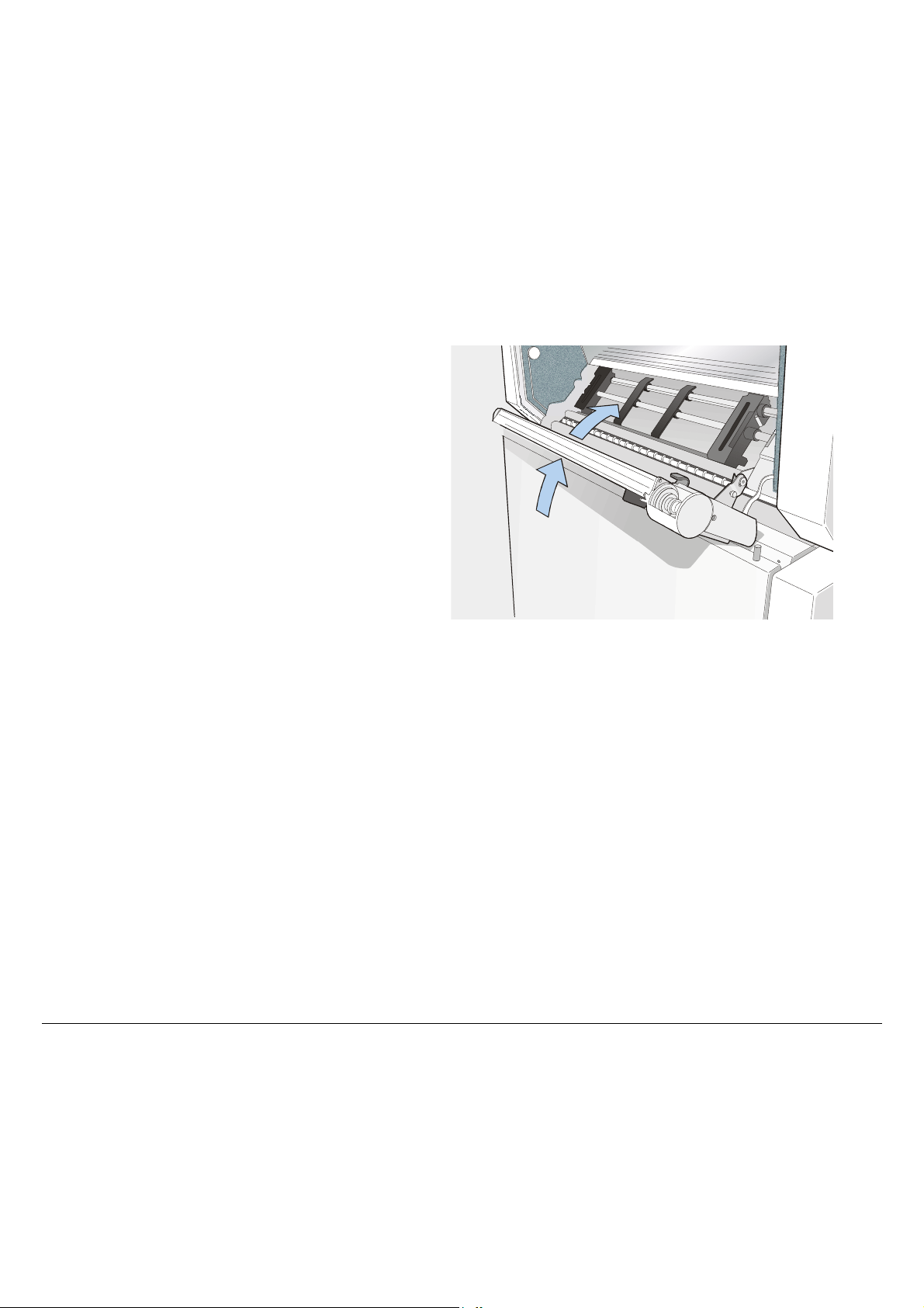
5. Rotate the Front2 push tractor onto
the Front 1 push tractor.
20
Page 25
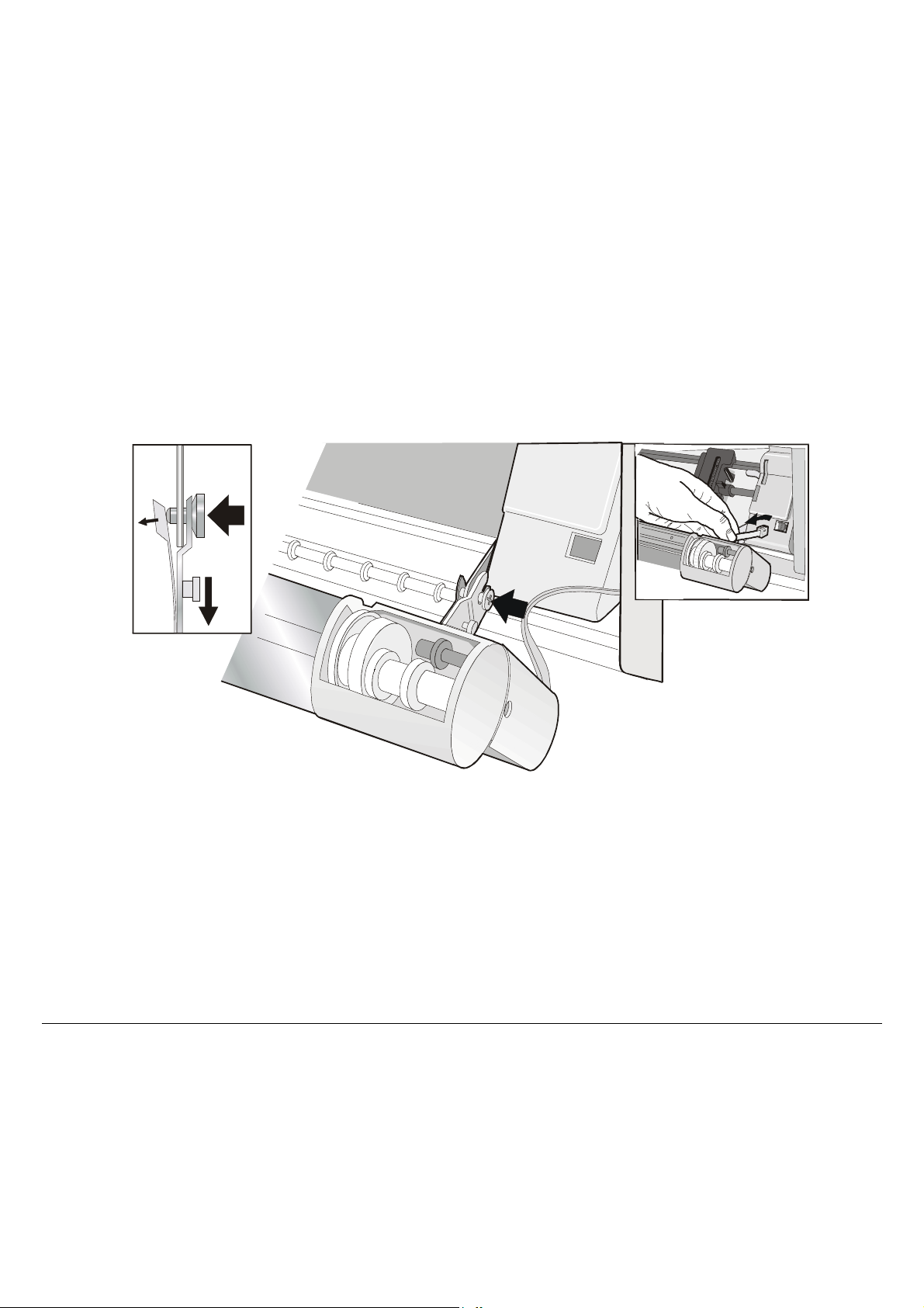
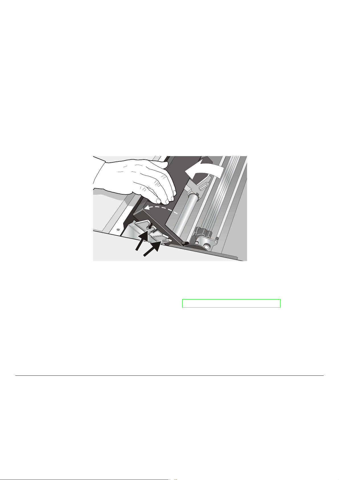
RReemmoovviinngg tthhee FFrroonntt22 PPuusshh TTrraaccttoorr
If you need to remove the upper push tractor, turn the printer off. Disconnect the connector cable
and press on the push buttons to disengage the Front2 push tractor.
21
Page 26

HHoosstt CCoommppuutteerr CCoonnnneeccttiioonn
This printer can be connected to your host computer via different available interfaces on two
alternative controllers.
Before connecting the interface cable, make sure that the printer and the host computer
F• irst Controller: this controller provides the following three interfaces: :
•
• A bidirectional IEEE1284 parallel interface
• A RS-232C serial interface
• An USB interface.
• Second Controller: this controller provides the following two interfaces:
• A bidirectional IEEE1284 parallel interface
• An Ethernet LAN interface.
are turned OFF.
22
Page 27
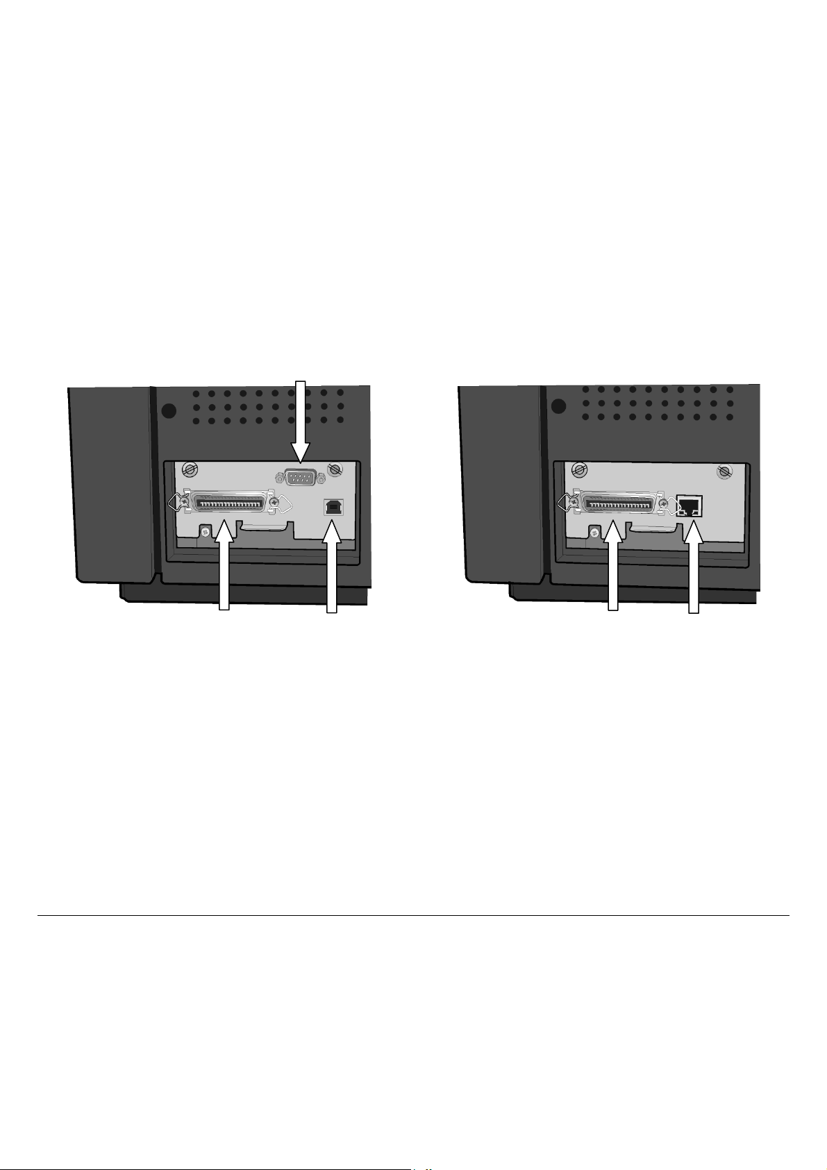
The interface connectors are located on the rear of the printer.
SERIAL
INTERFACE
PARALLEL
INTERFACE
USB
INTERFACE
PARALLEL
INTERFACE
LAN
INTERFACE
Insert the parallel interface cable into the parallel connector and fasten it by means of the clips.
Insert the serial interface cable into the serial connector and fasten it by means of the two screws (use
the screwdriver).
Insert the USB interface cable into the USB connector
Insert the LAN interface cable into the LAN connector.
23
Page 28

SSooffttwwaarree DDrriivveerr SSeelleeccttiioonn
At this point it is necessary to configure your printer for your application package. The installation
procedures depend upon the host environment.
Follow the instructions in the readme file you find on the CD-ROM.
In a WINDOWS 95/98/2000/XP/NT4.0/Millennium®/Vista environment the printer supports the
Plug & Play feature.
The printer drivers of all Compuprint printers can be found at the Internet Address
http://www.compuprint.com
24
Page 29
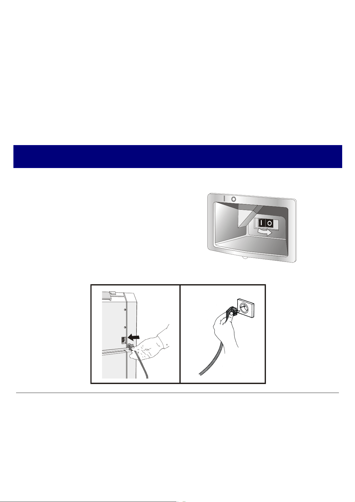
PPoowweerr CCoonnnneeccttiioonn
The power outlet must be compatible with the plug of the printer’s power cable.
1. Make sure the power outlet is near the printer location and easily accessible.
2. Make sure that the power switch is in 0
position (OFF).
3. Insert the power cable plug into the printer connector and the other power cable end into a
convenient outlet (the figure shows the European version).
Always use a grounded outlet.
25
Page 30
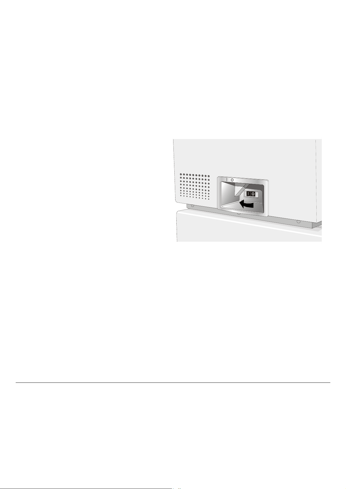
4. If you need to turn the printer on, press the
power switch in the I position (ON).
26
Page 31

SSeelleeccttiinngg tthhee DDiissppllaayy LLaanngguuaaggee
The display messages for this printer can be displayed in five different languages: English (Default),
French, German, Italian and Spanish. To select the language, that you prefer, proceed as follows:
1. Press the
message will be displayed:
2. When you release the PROGRAM key, the following messages will be displayed:
then,
then,
3. Press the ↓ key to enter the setup. The first setup item is displayed:
4. Press the ↓ key until the language first level function is displayed:
5. Press the → key to pass to the second level functions:
6. Press the ↓ key until the setup language is displayed:
PROGRAM key and keep it pressed while powering on the printer until the following
RELEASE KEYS
STARTING UP
10300 ver. x.xx
PRINT OUT? NO
EMUL. OPTIONS
FUNCTIONS
BUZZER YES
MENU ENGLISH
7. Press the → key to scroll the setup languages. When the desired language is displayed, press the
PROGRAM key to select it. The printer exits the setup. From now on the display messages appear
in the selected language.
27
Page 32

CCoonnffiigguurriinngg tthhee PPrriinntteerr
OOppeerraattoorr PPaanneell PPrreesseennttaattiioonn
The operator panel enables you to perform many of the printer functions including paper path
selections, font selection and the printer setup.
The operator panel consists of:
• A 16 character display (Liquid Crystal Display)
• Five led indicators
• Nine function keys
28
Page 33

DDiissppllaayy MMeessssaaggeess
The printer display is used to indicate the printer status or to request an user intervention.
When the printer is in Ready state, the display gives the following information:
• when paper is already loaded and the
printer is off line (
ON LINE indicator unlit):
OFF LINE M1
Printer Status
Current Macro
where:
OFF LINE
ON LINE
M1, M2, M3, M4
Indicates the printer status.
Indicate which of the four User Macros is currently used.
• when paper is already loaded and the
printer is on line (ON LINE indicator lit):
ON LINE M1
Printer Status
Current Macro
29
Page 34

• when there is no paper loaded and the
printer is off line (ON LINE indicator unlit):
Load Front1
Current Paper Path
where:
LOAD FRONT1
LOAD FRONT2
OFF LINE
ON LINE
M1, M2, M3, M4
Indicates that the currently selected paper path is out of paper.
The messages are displayed only for the available paper paths,
according to the installed devices.
Indicates the printer status.
Indicate which of the four User Macros is currently used.
• when there is no paper loaded and the
printer is on line (ON LINE indicator lit):
ON LINE M1
Printer Status
Current Macro
30
Page 35

The following messages appear to indicate other printer conditions or user intervention requests.
The list is in alphabetical order.
Message Description
ALTERNATE
BUSY M1
COVER OPEN
CLOSE COVER
EJECTING
INITIALIZING LAN
INVALID KEY
LOAD FRONT1
LOAD FRONT2
LOCKED MENU
This message appears to indicate that the Alternate functions of the operator
panel keys have been selected pressing the
This message appears to indicate that the printer is printing. It is busy.
When the printer cover is not closed correctly, the buzzer sounds and the display
shows alternately these two messages. Close the printer cover.
The printer is ejecting the paper out of the printer.
This message is displayed when the LAN is initialized (only if the LAN interface
is available).
This message is displayed if you push a key that is not allowed in the current
printer status.
These messages are displayed when the corresponding paper path is out of
paper.
The printer displays only the messages related to the installed devices.
When the access to the Printer Setups has been locked at the power on, the
printer displays this message.
ALTERNATE key.
MACRO CHANGING
MICRO FEED DOWN
The macro has been changed and the printer is updating the settings.
The paper is fed in microsteps downwards when pressing the ↓ arrow key.
31
Page 36

Message Description
MICRO FEED UP
OPER. INTERRUPTED
PARKING
PATH CHANGING
PRESS A KEY
NVM CHANGED
RELEASE KEYS
REMOTE CONTROL
RESET & BREAK
SELF TEST
The paper is fed in microsteps forwards when pressing the ↑ arrow key.
This message is displayed if the ALTERNATE key has been pressed to interrupt a
park procedure.
The printer is parking the fanfold paper.
The path has been changed and the printer is updating the settings.
The NVM has been changed. Press any key to set the printer.
This message is displayed when you can release the ON LINE key in the Self-test
selection or the
This message is displayed when the printer operates from remote control (only if
the LAN interface is present).
This message is displayed when the input buffer corresponding to the active
interface is cleared.
Printing the self-test page.
PROGRAM key in the Power-on Configuration procedure.
TEAR IF NECESS.
EJECT PAPER
TEAR IF NECESS.
PARK PAPER
These messages are displayed when the printer receives a paper parking
command and the TEAR NO item is selected for the tear-off function. Tear off the
fanfold then press the
These messages are displayed when the printer receives a paper parking
command. Tear off the fanfold paper if necessary and then press the
to park the paper.
PARK key to eject the paper.
PARK key
32
Page 37

Message Description
TEAR OFF PAPER
EJECT PAPER
TEAR OFF PAPER
PARK PAPER
UNLOCKED MENU
For the error messages see "Error Handling” later in this manual.
These messages are displayed when the printer receives a paper ejecting
command (TEAR NO item has been selected for the tear-off function) but was not
able to execute it, because the paper to be ejected is longer than 18 inch. Tear off
the fanfold paper and then press the
PARK key to eject the paper.
These messages are displayed when the printer has received a paper parking
command but was not able to execute it, because the paper to be parked is
longer than 18 inch. Tear off the fanfold paper and then press the
park the paper.
When the access to the Printer Setups has been unlocked at the power on, the
printer displays this message.
PARK key to
33
Page 38

IInnddiiccaattoorrss
E
A
1
2
Lit when the printer can receive and print data (printer online).
ON LIN
PROGRAM
LTERNATE
Fr on t
Fron t
Blinks when there is data in the buffer and the printer is offline.
Unlit when the printer is disabled and the buffer does not contain any data, or
during the initialization, setup or tests.
Lit when one of the printer setup procedures has been selected: Program
Configuration or Power-On Configuration.
Lit when the alternate function of the keys has been enabled pressing the
ALTERNATE key.
Lit when the Front1 paper path is selected.
Unlit when the Front1 paper path is not selected.
Lit when the Front2 paper path is selected.
Unlit when the Front2 paper path is not selected.
Lit when the printer can receive and print data (the printer is on-line).
Unlit when the printer is disabled (the printer is off-line).
Blinks when an error condition occurs.
34
Page 39

FFuunnccttiioonn KKeeyyss
Pressing the function keys it is possible to activate the functions indicated by the word or symbol
signed near the key. Each key may have different functions, according to the selected function modes:
Normal, Alternate or Program.
Normal Function
Alternate Function
Program Function
The normal function of the keys is written above the keys and does not require any
previous action to select it.
The alternate function of the keys is written below the keys and is selected pressing
the
ALTERNATE key.
When the alternate function of the keys is selected, the
the display shows ALTERNATE.
The program function of the keys is selected pressing the
• If you press the key while powering the printer on, the Power-On Configuration
is selected.
• If you press the key when the printer is enabled without printing or disabled
(
ON LINE indicator unlit), the Program Setup is selected.
In the Program Setup mode only the four arrow keys and the
enabled and the
PROGRAM indicator is lit.
35
ALTERNATE indicator is lit and
PROGRAM key, where:
PROGRAM key are
Page 40

ON LINE Key
ON LINE
Normal
Function
Program
Function
PROGRAM Key
PROGRAM
Normal
Function
Program
Function
Enables or disables the printer.
• If this key is pressed while powering the printer on, the self test is printed;
the printout is stopped pressing this key again.
• In an error condition, once the error cause has been removed, press this key
to enable the printer
Pressing this key, the input buffer is cleared. The message RESET & BREAK is
displayed.
Enables the printer setups as follows:
• Pressing this key while powering on the printer, the Power-On
Configuration is selected.
• Pressing this key when the printer is enabled without printing or disabled
the Program Setup is enabled (
PROGRAM indicator lit).
Exits the printer setups.
MACRO Key
MACRO
→
Normal
Function
Program
Function
Selects one of the user macros (Macro 1, Macro 2, Macro 3 or Macro 4). If you
want to select the displayed macro, wait for 2 seconds without pressing any
key and the parameters of this macro will be set.
Scrolls the parameters of the functions or macros forwards.
36
Page 41

FONT Key
FONT
Normal
Function
←
Program
Function
LF Key
LF
MICRO FEED
↑
Normal
Function
Alternate
Function
Program
Function
LOAD/FF Key
LOAD/FF
MICRO FEED
Normal
Function
Alternate
Function
Selects the font to be used with the currently selected pitch. The selected font
is valid until the printer is turned off or a new font is selected using this key.
Scrolls the parameters of the functions or macros backwards.
Performs a line feed according to the current line spacing settings.
Moves the paper forward in microsteps. Keeping the key pressed the paper is
moved continuously at increasing speed.
Scrolls the setup and macro functions backwards.
Executes a Form Feed (FF). When paper is loaded into the printer, it advances
to the following page; if no paper is loaded, it is positioned for printing.
Moves the paper backward in microsteps. Keeping the key pressed the paper is
moved continuously at increasing speed.
↓
Program
Scrolls the setup and macro functions forwards.
Function
37
Page 42

ALTERNATE Key
ALTERNATE
Normal
Function
Alternate
Function
TEAR/PITCH Key
TEAR
PITCH
Normal
Function
Alternate
Function
Enables the alternative key functions.
If the printer is receiving print data, press the
ALTERNATE key.
If no printing data are in the print buffer, pressing the
ON LINE key before pressing the
ALTERNATE key, the printer
goes offline.
The display then shows
the keys is enabled (
ALTERNATE to indicate that the Alternate Function of
ALTERNATE indicator lit).
May be used to abort paper parking procedure. See also “How to Handle the
Paper Parking”, later in this manual.
When the printer is in Program Setup Mode, this key is disabled.
Disables the alternative key functions.
Moves the paper to the tear-off position (TEAR NORMAL function must be selected
in the Program Setup).
Selects the pitch to be used with the currently selected font. The selected pitch is
valid until the printer is turned off.
38
Page 43

PATH/PARK Key
PATH
PARK
Normal
Function
Alternate
Function
Key Combinations
ONLINE + MACRO + TEAR
Selects one of the paper paths in offline status. The parameters of the displayed
path are set after 2 seconds without pressing any key.
Parks the paper in the currently selected paper path.
Normal
Function
Lock or unlock the access to the printer setups. See later
“How to Lock/Unlock the Printer Setups” section.
39
Page 44

PPrriinntteerr SSeettuuppss
The main printer setup parameters can be selected via the operator panel. The setup parameters are
divided into two printer setups, the Power-On Configuration, that allows a complete configuration at
installation time according to the hardware and the emulation types, and the Program Setup, that
allows you to set the functions that are the most useful in your daily job. These settings can be
selected when the printer is online without printing or offline (ON LINE indicator unlit) and stored in
the NVM.
EEnntteerriinngg tthhee PPrriinntteerr SSeettuuppss
• Press the PROGRAM key and keep it pressed at the printer power on until the RELEASE KEYS
message is displayed to select the Power-On Configuration.
• Press the PROGRAM key when the printer is online without printing or offline (ON LINE
indicator unlit) to select the Program Setup.
MMoovviinngg wwiitthhiinn tthhee PPrriinntteerr SSeettuup
The arrow keys ↑, ↓, ←, → are used to move within the different functions inside the Printer Setups.
See the following description of the setup items.
pss
40
Page 45

LLeeaavviinngg tthhee PPrriinntteerr SSeettuuppss
• Pressing the PROGRAM key in the Power-On Configuration the printer exits from the setup and
the new settings will be automatically saved.
• Pressing the PROGRAM key in the Program Setup, the following choice is offered for the storage of
the values set:
STORE? QUIT
STORE? SAVE
STORE? CURRENT
Press the → or ← keys to scan these selections forward and backwards. When the desired setting is
displayed, press the PROGRAM key to exit from the Setup.
The new settings are not activated and the old settings remain valid.
The new settings are stored permanently in the NVM (Non Volatile
Memory).
The new settings remain valid until the printer is turned off.
41
Page 46

PPoowweerr--OOnn CCoonnffiigguurraattiioonn
The default values of the various functions are indicated in bold.
EEnntteerriinngg tthhee PPoowweerr--OOnn CCoonnffiigguurraattiioonn
1. Make sure that the printer is turned off.
2. Press and hold the PROGRAM key pressed while powering on the printer until the RELEASE KEYS
message is displayed. As soon as the PROGRAM key gets released, the following message will be
displayed:
STARTING UP
then,
10300 ver. x.xx
then,
PRINT OUT? NO
42
Page 47

Main Structure
This figure shows the structure of the Power-On Configuration and how to move inside the Setup.
43 44
Page 48

The setup item Functions groups the following printer functions:
• Buzzer setting,
• Paper loading sequence,
• Bar code density,
• Text printing direction,
• Graphics printing direction,
• Bar code printing direction,
• Graphics printing speed,
• Paper path at power on,
• Language of the display messages,
• Paper tractor jam sensors,
• Tear-off position adjustment.
Printout of the Printer Settings
PRINT OUT? NO
↓
EMUL. OPTIONS
→ or ←
PRINT OUT? YES
PRINT OUT? NO
PRINT OUT? YES
The Setup is not printed.
The printer setup is printed showing the currently selected values. The
printout starts as soon as you select this value.
Page 49

Emulation Options
This setup defines the available options according to the selected emulation and is structured as
follows:
Options
45 46
Page 50

Setting the Emulation Options
Printer Emulation
PRINT OUT? NO EMUL. OPTIONS
↑
EMUL. OPTIONS
↓
INTERFACE
EMUL. IBM 2391
EMUL. ANSI
CHAR. SET CS2
→
↑
EMUL. EPSON LQ
EMUL. IBM XL24
EMUL. IBM XL24AGM
↓
→ or ←
→ or ←
→ or ←
→ or ←
→ or ←
EMUL EPSON LQ
EMUL IBM XL24
EMUL IBM XL24AGM
EMUL. IBM 2391
EMUL. ANSI
The printer uses the EPSON LQ Series emulation.
The printer uses the IBM Proprinter XL24 emulation.
The printer uses the IBM Proprinter XL24 AGM emulation.
The printer uses the IBM Personal 2391+ emulation.
The printer uses the ANSI 3.64 emulation.
If ANSI emulation has been selected, specific ANSI parameters are available. See the “ANSI
options” section later in this manual.
Page 51

EPSON Character Sets
EMUL. EPSON LQ
↑
CHAR. SET CS1
CHAR. SET CS2
CHAR. SET ITALIC
↓
NATION CP437
→ or ←
→ or ←
→ or ←
These items select the character set to be used in EPSON emulation.
IBM Character sets
EMUL. IBM xxx
↑
CHAR. SET CS1
CHAR. SET CS2
↓
NATION CP437
→ or ←
→ or ←
These items select the character set to be used in IBM Proprinter emulation.
47
Page 52

EPSON National Character sets
CHAR. SET CS2
↑
NATION CP437
NATION …
NATION LATIN A1
↓
AUTO CR YES
→ or ←
→ or ←
→ or ←
The following national character sets are available:
CP 437 CP437 G 96GREEK CP850 CP851 CP 852 CP 853 CP 855
CP 857 CP 858 CP 860 CP 862 CP 863 CP 864 CP 865 CP 866
CP 867 CP 876 CP 877 CP 1250 CP 1251 CP 1252 CP 1253 CP 1254
CP 1255 CP 1256 CP 1257 GOST TASS MAZOWIA ISO 8859/1 ISO 8859/2
ISO 8859/3 ISO 8859/4 ISO 8859/5 ISO 8859/6 ISO 8859/7 ISO 8859/8 ISO 8859/9 ISO 8859/15
CP 437SL CP 1098 UKRAIN KOI8-U FARSI1 FARSI2 USA FRANCE
GERMANY ENGLAND DENMARK1 SWEDEN ITALY SPAIN1 JAPAN NORWAY
DENMARK2 SPAIN2 LATIN A1
The CP 858 and ISO 8859/15 character sets contain the Euro character.
48
Page 53

IBM National Character Sets
CHAR. SET CS2
↑
NATION CP437
NATION …
NATION FARSI2
↓
AUTO CR NO
→ or ←
→ or ←
→ or ←
The following national character sets can be selected:
CP 437 CP437 G 96GREEK CP850 CP851 CP 852 CP 853 CP 855
CP 857 CP 858 CP 860 CP 862 CP 863 CP 864 CP 865 CP 866
CP 867 CP 876 CP 877 CP 1250 CP 1251 CP 1252 CP 1253 CP 1254
CP 1255 CP 1256 CP 1257 GOST TASS MAZOWIA ISO 8859/1 ISO 8859/2
ISO 8859/3 ISO 8859/4 ISO 8859/5 ISO 8859/6 ISO 8859/7 ISO 8859/8 ISO 8859/9 ISO 8859/15
CP 437SL CP 1098 UKRAIN KOI8-U FARSI1 FARSI2
TThhee CCPP 885588 aanndd IISSOO 88885599//1155 cchhaarraacctteerr sseettss ccoonnttaaiinn t
thhee EEuurroo cchhaarraacctteerr..
49
Page 54

CR Code Behavior
NATION xxx
↑
AUTO CR NO
AUTO CR YES
↓
AUTO LF NO
→ or ←
→ or ←
AUTO CR NO
No automatic carriage return is performed after a LF, VT or ESCJ code.
Default value in IBM emulation.
AUTO CR YES
The printer performs an automatic carriage return after a LF, VT or ESCJ code.
Default value in EPSON emulation.
50
Page 55

LF Code Behavior
AUTO CR xx
↑
AUTO LF NO
AUTO LF YES
AUTO LF HOST
↓
20 CPI IBM NO
or
BAR CODE NATIV
→ or ←
→ or ←
→ or ←
AUTO LF NO
AUTO LF YES
AUTO LF HOST
No Automatic LF after CR.
Automatic LF after CR.
Only in EPSON emulation. The printer checks the AUTOFEEDXT signal
coming from the host and executes an automatic LF after CR, if the signal is
low.
51
Page 56

IBM Compressed Printing
These items are displayed only if the IBM emulation is selected.
AUTO LF NO
↑
20 CPI IBM NO
20 CPI IBM YES
↓
BAR CODE NATIV
→ or ←
→ or ←
20 CPI IBM NO
20 CPI IBM YES
The compressed printing is performed at 17.1 cpi.
The compressed printing is performed at 20 cpi.
52
Page 57

Bar code mode
20 CPI IBM NO
or
AUTOLF NO
↑
BAR CODE NATIV
BAR CODE ALTER
↓
EMUL. OPTIONS
→ or ←
→ or ←
BAR CODE NATIV
BAR CODE ALTER
Enables bar code printing using the native commands (DC4, DC4, …).
Enables bar code printing using ANSI commands even if the emulation in use is
EPSON or IBM.
53
Page 58

Interface Settings
Depending upon the installed Controller Board, the printer can be equipped with different
interfaces to connect to the host system. The possible interfaces are:
- Parallel Centronics
- Serial 232C
- USB
- Ethernet LAN 10/100
The following paragraphs describe how to configure the parameters of the interfaces.
Interface
(*) This item is displayed only if the interface board (Controller Board) installed on the unit is
equipped with this interface.
AUTO
PARALLEL
SERIAL
USB
LAN
All the interfaces installed onto the interface board (controller) are active and the hot
port feature is operative.
Only the Centronics Parallel Interface is active. Hot Port is not operative.
Only the Serial RS232 Interface is active. Hot Port is not operative.
Only the USB Interface is active. Hot Port is not operative.
Only the Ethernet LAN Interface is active. Hot Port is not operative.
54
Page 59

Parallel Interface
This setup defines the use of the parallel interface and is structured according to the interface specific
parameters.
Parallel Interface Parameters
55 56
Page 60

Setting the Parallel Interface Parameters
Interface Type
INTERFACE PARALL INTERFACE
↑
PARALL INTERFACE
↓
SERIAL INTERFACE
1284 BIDIR. I/F
CX. PARALLEL I/F
→
CX. PARALLEL I/F
SELECT-IN HOST
↑
1284 BIDIR. I/F
↓
Bidirectional IEEE 1284 parallel interface.
Centronics type parallel interface (mono-directional).
→ or ←
→ or ←
Setting the Select-In Signal
1284 BIDIR . I/F
↑
SELECT-IN HOST
SELECT-IN ON
↓
DATA BITS 8
→ or ←
→ or ←
SELECT-IN HOST
SELECT-IN ON
The printer checks the SELECT-IN signal coming from the host.
The SELECT-IN signal of the parallel interface is ignored and treated always
as ON.
Page 61

Number of Data Bits
SELECT-IN HOST
↑
DATA BITS 8
DATA BITS 7
↓
INP. BUFFER 2K
→ or ←
→ or ←
Selection of the number of data bits: 7 or 8.
Input Buffer Size
DATA BITS 8
↑
INP. BUFFER 256
INP. BUFFER 2K
INP. BUFFER 12K
INP. BUFFER 32K
INP. BUFFER 64K
INP. BUFFER 128K
↓
PARALL. INTERFACE
→ or ←
→ or ←
→ or ←
→ or ←
→ or ←
→ or ←
Selects the input buffer size.
57
Page 62

Serial Interface
The following Serial Interface Parameters will display only if the Serial Interface is present.
This setup defines the use of the serial interface and is structured according to the interface
specific parameters.
Serial Interface Parameters
58 59
Page 63

Setting the Serial Interface Parameters
Interface Type
PARALL INTERFACE
↑
SERIAL INTERFACE
↓
FUNCTIONS
SERIAL I/F 232
→
SERIAL INTERFACE
↑
SERIAL I/F 232
↓
BAUD 9600
→ or ←
It is available the serial interface RS-232/C only.
Page 64

Baud Rate
SERIAL I/F 232
↑
BAUD 300
BAUD 600
BAUD 1200
BAUD 2400
BAUD 4800
BAUD 9600
BAUD 19200
BAUD 38400
BAUD 115200
↓
DATA BITS 8
→ or ←
→ or ←
→ or ←
→ or ←
→ or ←
→ or ←
→ or ←
→ or ←
→ or ←
The baud rate is selected in bits per second. The above values can be selected.
Number of Data Bits
BAUD 9600
↑
DATA BITS 8
DATA BITS 7
↓
PARITY NONE
→ or ←
→ or ←
Selection of the number of data bits: 7 or 8.
60
Page 65

Parity Check
DATA BITS 8
↑
PARITY NONE
PARITY ODD
PARITY EVEN
PARITY MARK
PARITY SPACE
↓
HANDSHAKE DTR
PARITY NONE
PARITY ODD
PARITY EVEN
PARITY MARK
PARITY SPACE
→ or ←
→ or ←
→ or ←
→ or ←
→ or ←
Data does not have a parity bit, i.e. 8 bit data are transferred and the parity
check is disabled.
Parity check is enabled for odd parity.
Parity check is enabled for even parity.
Parity check is disabled and the transmitted parity bit is always a Mark.
Parity check is disabled and the transmitted parity bit is always a Space.
61
Page 66

Handshake Protocol
PARITY NONE
↑
HANDSHAKE DTR
HANDSHAKE XONXOF
↓
CONNECTION LOCAL
HANDSHAKE DTR
HANDSHAKE XONXOF
Connection Type
HANDSHAKE DTR
↑
CONNECTION LOCAL
CONNECT. REMOTE
↓
INP. BUFFER 2K
→ or ←
→ or ←
The Handshake is performed using the DTR Protocol.
The Handshake is performed using the XON-XOFF Protocol.
→ or ←
→ or ←
Selects the connection type: local or remote.
62
Page 67

Input Buffer Size
CONNECTION LOCAL
↑
INP. BUFFER256
INP. BUFFER 2K
INP. BUFFER12K
INP. BUFFER32K
INP. BUFFER64K
INP. BUFFER128K
↓
SERIAL INTERFACE
→ or ←
→ or ←
→ or ←
→ or ←
→ or ←
→ or ←
Selects the input buffer size.
63
Page 68

LAN Interface
The following LAN interface parameters will display only if the Ethernet 10/100 Mbit interface
is present.
This setup defines the use of the LAN interface and is structured according to the interface specific
parameters.
LAN Interface Parameters
64 65
Page 69

IP Assignment
PARALL INTERFACE
↑
LAN INTERFACE
↓
FUNCTIONS
INIT IP ADDRESS 127.000.000.000
→
LAN INTERFACE
↑
IP ASSIGN FIXED
IP ASSIGN DHCP
↓
IP ASSIGN FIXED
IP ASSIGN DHCP
Init IP Address
IP ASSIGN FIXED
↑
INIT IP ADDRESS 000.000.000.000
INIT IP ADDRESS …
INIT IP ADDRESS 255.255.255.255
↓
INIT NET MASK 255.255.254.000
Assigns the static or fixed IP address.
Assigns the dynamic IP address (DHCP protocol).
→ or ←
→ or ←
→ or ←
→ or ←
→ or ←
These values set the INIT IP address. The IP address is represented by a decimal notation where the
decimal values are divided by points in four fields. Each field ranges between 0 and 255. Use the ←
or → keys to increase or decrease the values in one field and the ↓ or ↑ keys to move to the next field
(↓ to move to the right and ↑ to move to the left). The default value is
127.000.000.000.
Page 70

Init Net Mask
INIT IP ADDRESS 127.000.000.000
↑
INIT NET MASK 000.000.000.000
INIT NET MASK …
INIT NET MASK 255.255.255.255
→ or ←
→ or ←
→ or ←
↓
DEF. GATEWAY ID 000.000.000.000
These values set the INIT net mask number. This number is represented by a decimal notation
where the decimal values are divided by points in four fields. Each field ranges between 0 and
255. Use the ← or → keys to increase or decrease the values in one field and the ↓ or ↑ keys to move
to the next field (↓ to move to the right and ↑ to move to the left). The default value is
255.255.254.000.
ID Default Gateway
INIT NET MASK 255.255.254.000
↑
DEF. GATEWAY ID 000.000.000.000
DEF. GATEWAY ID …
DEF. GATEWAY ID 255.255.255.255
↓
INIT HOST NAME CMP_xxxxxx
→ or ←
→ or ←
→ or ←
These values set the ID default gateway number. This number is represented by a decimal notation
where the decimal values are divided by points in four fields. Each field ranges between 0 and 255.
Use the ← or → keys to increase or decrease the values in one field and the ↓ or ↑ keys to move to the
next field (↓ to move to the right and ↑ to move to the left).
66
Page 71

Init Host Name
DEF. GATEWAY ID 000.000.000.000
↑
INIT HOST NAME ……………
PROGRAM key
↓
INIT WORKGROUP CMP_GROUP
→ or ←
The host is identified by a name. This function allows to create the name of the init host using a 14character string. Use the ← or → keys to increase or decrease the values in one field and the ↓ or ↑
keys to move to the next field (↓ to move to the right and ↑ to move to the left). Press the PROGRAM
key to save the selected init host name. The default name is CMP_xxxxxx.
Init Workgroup Name
INIT HOST NAME CMP_xxxxxx
↑
INIT WORKGROUP ……………
PROGRAM key
↓
→ or ←
SMTP ENABL. NO
The workgroup is identified by a name. This function allows to create the name of the workgroup
using a 14-character string. Use the ← or → keys to increase or decrease the values in one field and
the ↓ or ↑ keys to move to the next field (↓ to move to the right and ↑ to move to the left). Press the
PROGRAM key to save the selected init workgroup name. The default name is workgroup.
67
Page 72

Enable/Disable the SMTP Service
INIT WORKGROUP workgroup
↑
SMTP ENABL. NO
→ or ←
SMTP ENABL. YES
↓
LAN INTERFACE MAIL SERV.ADDRES 000.000.000.000
↓
SMTP ENABL. NO
Disables the SMTP (Simple Mail Transfer Protocol) service, that is disables
the reception/transfer/error service of the e-mail.
SMTP ENABL. YES
Enables the SMTP (Simple Mail Transfer Protocol) service, that is enables
the reception/transfer/error service of the e-mail.
Mail Server Address
This item is displayed only if the SMTP ENABL. function is selected in YES.
SMTP ENABL. YES
↑
MAIL SERV.ADDRES 000.000.000.000
MAIL SERV.ADDRES …
MAIL SERV.ADDRES 255.255.255.255
↓
EMAIL ADDRESS 000.000.000.000
→ or ←
→ or ←
→ or ←
These values set the mail server address. This number is represented by a decimal notation where the
decimal values are divided by points in four fields. Each field ranges between 0 and 255. Use the ← or
→ keys to increase or decrease the values in one field and the ↓ or ↑ keys to move to the next field (↓
to move to the right and ↑ to move to the left).
68
Page 73

E-mail Address
This item is displayed only if the SMTP ENABL. function is selected YES.
MAIL SERV.ADDRES 000.000.000.000
↑
EMAIL ADDRESS xxxxxxxxxxx
↓
SENDER ADDRESS xxxxxxxxxxx
→ or ←
This function allows to write the e-mail address where you can notify the failures. Use the ← or →
keys to increase or decrease the values in one field and the ↓ or ↑ keys to move to the next field (↓ to
move to the right and ↑ to move to the left). Press the PROGRAM key to save the e-mail address.
Sender Address
This item is displayed only if the SMTP ENABL. function is selected YES.
EMAIL ADDRESS xxxxxxxxxxx
↑
SENDER ADDRESS xxxxxxxxxxx
↓
LAN INTERFACE
→ or ←
This function identifies the address of the sender’s e-mail using a string of characters. Use the ← or
→ keys to increase or decrease the values in one field and the ↓ or ↑ keys to move to the next field (↓
to move to the right and ↑ to move to the left). Press the
PROGRAM key to save the sender’s e-mail
address.
69
Page 74

Functions
This item groups various printer functions, with which you can configure the printer.
Functions Group Parameters
70 71
Page 75

Setting the Functions Group Items
Enable/Disable the Buzzer
SERIAL INTERFACE (*)
or
LAN INTERFACE (**) FUNCTIONS
↑
FUNCTIONS
↓
RETURN TO MFG: NO
SEQUENCE NONE
↑
BUZZER YES
→
BUZZER NO
↓
→ or ←
→ or ←
Enable or disables the buzzer.
(*) If Serial Interface is present.
(**) If LAN Interface is present.
Page 76

Paper Loading Sequence
BUZZER YES
↑
SEQUENCE NONE
SEQ. F1+F2 PUSH
↓
BAR CODE
TThheessee iitteemmss aarree ddiissppllaayyeedd oonnllyy iiff tthhee aacccceessssoorriieess ttoo wwhhiicchh tthheeyy rreeffeerr aarree iinnssttaalllleedd..
SEQUENCE NONE
SEQ. F1+F2 PUSH
Bar Code Density
SEQUENCE NONE
↑
→ or ←
→ or ←
120 DPI
The paper is fed only through the path selected by operator panel.
The paper is fed firstly with the Front1 push tractor and successively
through the Front2 push tractor option.
BAR CODE 120DPI
BAR CODE 180DPI
↓
TEXT DIRECT BI
→ or ←
→ or ←
Selects the bar code print density: 120 or 180 dpi.
72
Page 77

Text Print Direction
BAR CODE 120DPI
↑
TEXT DIRECT BI
TEXT DIRECT UNI
↓
GRAPH DIRECT BI
→ or ←
→ or ←
Selects the print direction for text: bidirectional or unidirectional.
Graphics Print Direction
TEXT DIRECT BI
↑
GRAPH DIRECT BI
GRAPH DIRECT UNI
↓
BARCODES DIR. UNI
→ or ←
→ or ←
Selects the print direction for graphics: bidirectional or unidirectional.
73
Page 78

Bar Codes Print Direction
GRAPH DIRECT BI
↑
BARCODES DIR. BI
BARCODES DIR. UNI
↓
GRAPH H.S. YES
→ or ←
→ or ←
Selects the print direction for bar codes: bidirectional or unidirectional.
Graphics Printing Speed Selection
BARCODES DIR. UNI
↑
GRAPH H.S. NO
GRAPH H.S. YES
↓
P. ON PATH MACRO
→ or ←
→ or ←
GRAPH H.S. NO
GRAPH H.S. YES
Selects graphics printing (bit image data) at normal speed.
Selects graphics printing (bit image data) at high speed.
74
Page 79

Paper Path at Power-On
GRAPH H.S. YES
↑
P. ON PATH MACRO
P. ON PATH LAST
↓
MENU ENGLISH
P. ON PATH MACRO
P. ON PATH LAST
→ or ←
→ or ←
The paper path at power-on is the one from the default Macro.
The paper path at power-on is the last one that was selected before the printer
was powered off.
75
Page 80

Selection of the Language of the Display Messages
P. ON PATH MACRO
↑
MENU ENGLISH
MENU ITALIANO
MENU FRANCAIS
MENU ESPANOL
MENUE DEUTSCH
↓
F1 JAM SENS. Y
→ or ←
→ or ←
→ or ←
→ or ←
→ or ←
These items are self explaining.
See also “Selecting the Display Language” before in this manual.
76
Page 81

Enable/Disable Lower Tractor Jam Sensor
MENU ENGLISH
↑
F1 JAM SENS. Y
F1 JAM SENS. N
→ or ←
→ or ←
↓
F2 JAM SENS. Y
or
TEAR ADJUST:xxx
F1 JAM SENS. Y
F1 JAM SENS. N
Enables the paper jam sensor located in the 6 pin Front1 push tractor option.
Disables the paper jam sensor located in the 6 pin Front1 push tractor option.
Enable/Disable Upper Tractor Jam Sensor
This item is displayed only if the Front2 push tractor option is installed.
F1 JAM SENS. Y
↑
F2 JAM SENS. Y
F2 JAM SENS. N
↓
TEAR ADJUST: xxx
→ or ←
→ or ←
F2 JAM SENS. Y
F2 JAM SENS. N
Enables the paper jam sensor located in the 6 pin Front2 push tractor option.
Disables the paper jam sensor located in the 6 pin Front2 push tractor option.
77
Page 82

Adjusting the Tear-Off Position
F2 JAM SENS. Y
or
F1 JAM SENS. Y
or
MENU ENGLISH
↑
TEAR ADJUST: +30
TEAR ADJUST: ...
TEAR ADJUST: -390
↓
FUNCTIONS
TEAR ADJUST: xxx
→ or ←
→ or ←
→ or ←
These values adjust the distance between the Tear-Off Perforation and
the Tear-Off Bar. The values correspond to 1/180 inch units, i.e. the
tuning ranges between +1/6 and -13/6 inch. 0 is the default value.
See also “How to Use the Tear-Off Function”, later in this Chapter.
78
Page 83

Resetting to Factory Default Values
With the BACK TO MFG function it is possible to reset all items in the Power On Configuration Setup
and in the Program Setup to their factory default values. This may be useful if you do not remember
the values you set in the setups, or because you simply changed you mind about the settings you
have just done. The default values for the setup items are indicated in bold.
FUNCTIONS
↑
BACK TO MFG: NO
↓ or PROG
PRINT OUT ?
→ or ←
BACK TO MFG: YES
If you want to select BACK TO MFG: YES, you have to exit from this item using the ↑ or the ↓ key, in
order to confirm the selection of this value.
At this point, the Power On Configuration Setup procedure is finished. If you exit pressing the ↓ and
the PROGRAM key, the new settings will be saved.
Do not power off the printer before all data have been written into the NVM and the printer has
returned online.
79
Page 84

PPrrooggrraamm SSeettuupp
The default values of the various functions are indicated in bold.
EEnntteerriinngg tthhee PPrrooggrraamm SSeettuupp
Press the PROGRAM key when the printer is turned on and is offline or online without printing. The
following message will be displayed:
The figure in the following page shows the structure and how to move inside the Program Setup.
PRINT OUT? NO
80
Page 85

Main Structure
Print out? No
User Macro
Config. Menu No
Hex Dump No
Print out? Yes
Macro # 1
Line sp. 6 lpi
...
MACRO PARAMETER BLOCK
Next Macro? No
Config. Menu Yes
Hex Dump Yes
Line sp. ...
Next Macro? Yes
…
Macro # 4
Parall. Interface
Serial Interface
The items define the following parameters:
• Four user macros
• The direct access to the Power-On Configuration
• Hexadecimal printout
81
LAN Interface
CONFIGURATION MENU BLOCK
Page 86

Printout of the Printer Settings
PRINT OUT? NO
↓
USER MACRO
→ or ←
PRINT OUT? YES
PRINT OUT? NO
PRINT OUT? YES
The setup is not printed.
The printer setup is printed. The printout starts as soon as you select this value.
NOTE: The Program setup printout indicates:
• the currently selected values,
• the current selected macro is marked with the #x# symbols (USER MACRO #x#),
• the current firmware release.
82
Page 87

User Macro
The USER MACRO item allows to prepare four printing environments (MACRO#1, MACRO#2, MACRO#3
and MACRO#4). Each macro is composed of a group of parameters which define a configuration that
can then be recalled to easily set the printer for four printing environments.
Selection of the User Macro
PRINT OUT? NO USER MACRO
↓
USER MACRO
↓
CONFIG MENU NO MACRO#3
MACRO#4
→
MACRO#2
↑
MACRO#1
↓
LINE SP. 6 LPI
→ or ←
→ or ←
→ or ←
→ or ←
Selection of the macro for which you intend to set the parameters.
WWhheenn aa nneeww mmaaccrroo iiss sseelleecctteedd aanndd tthhee ffaannffoolldd ppaappeerr iiss pprreesseenntt iinn tthhee ppaappeerr ppaatthh s
seett iinn tthhee
pprreevviioouuss mmaaccrroo,, iitt wwiillll bbee aauuttoommaattiiccaallllyy ppaarrkkeedd ((TTEEAARR IIFF NNEECCEESSSS//PPAARRKK PPAAPPEERR iiss ddiissppllaayyeedd)).. TTeeaarr
ooffff tthhiiss ffaannffoolldd ppaappeerr aanndd pprreessss PPAARRKK kkeeyy..
83
Page 88

User Macro Parameters
User macro
Macro #1 Macro #2
Li ne sp. 6 lpi
Line Sp. Lock No
Length 6 6 Li nes
Top of Form 0
Ignore F.F. No Ignore F.F. Yes
Sk ipo ver 0
Draft Mode Norm
Quality LQ
Font Draft
Pi tc h 10 cp i
Macro #3 Macro #4
Li ne s p. ...
Li ne Sp . L ock Y es
Length ...
Top of Form …
Skipover …
Draft Mode …
Qual it y N LQ
Font …
Pitch …
15&24 cpi Norm al 15&24 cpi Micro
Pitch Lock No
Left Margin 0
Pi tc h Lock Ye s
Left Margin …
84 85 86
Page 89

Page 90

Line Spacing
MACRO#1
MACRO#1
→
LINE SP. 8 LPI
LINE SP. 12 LPI
↑
LINE SP. 6 LPI
LINE SP. 3L/30MM
LINE SP. 4L/30MM
LINE SP. 6L/30MM
LINE SP. 8L/30MM
LINE SP.12L/30MM
↓
LINE SP. LOCK NO
→ or ←
→ or ←
→ or ←
→ or ←
→ or ←
→ or ←
→ or ←
→ or ←
These values define the line spacing in lines/inch (6, 8, 12) or in lines per 30 mm (3, 4, 6, 8, 12).
Line Spacing Lock
LINE SP. 6 LPI
↑
LINE SP. LOCK NO
LINE SP. LOCK YES
↓
LENGTH xxx
→ or ←
→ or ←
LINE SP. LOCK NO
LINE SP. LOCK YES
Setting this item, the value set for vertical spacing can be changed by software
or operator panel.
Setting this item, the value set for vertical spacing cannot be changed by
software but only by operator panel.
Page 91

Page Length
LINE SP. LOCK NO
↑
LENGTH 1 LINE
LENGTH ... LINES
LENGTH 244 LINES
↓
TOP OF FORM 0
→ or ←
→ or ←
→ or ←
These items set the page length for fanfold paper in number of lines depending on the current
vertical spacing. Default value is 66 lines.
Top of Form
LENGTH xx
↑
TOP OF FORM 0
TOP OF FORM …
TOP OF FORM xxx
→ or ←
→ or ←
→ or ←
↓
IGNORE F.F. NO
These items set the top of form. The values range between 0 and the page length - 1.
87
Page 92

Form Feed (FF) Command
TOP OF FORM 0
↑
IGNORE F.F. NO
IGNORE F.F. YES
↓
SKIPOVER 0
IGNORE F.F. NO
IGNORE F.F. YES
Skip Over Perforation
IGNORE F.F. NO
↑
SKIPOVER 0
SKIPOVER …
→ or ←
→ or ←
The Form Feed (FF) command is always executed.
The Form Feed (FF) command is ignored when the paper is in the top of form
(TOF) position. A Form Feed can be performed if the LOAD/FF key is pressed.
→ or ←
→ or ←
SKIPOVER xxx
↓
DRAFT MODE NORM
→ or ←
These items set the skipover perforation. The values range between 0 and the page length - 1.
88
Page 93

Draft Print Mode Selection
SKIPOVER 0
↑
DRAFT MODE NORM
DRAFT MODE BEST
DRAFT MODE HS
↓
QUALITY LQ
→ or ←
→ or ←
→ or ←
DRAFT MODE NORM
DRAFT MODE BEST
The printer performs the draft printing at normal speed.
The printer performs the draft printing at low speed to obtain better quality
printing.
DRAFT MODE HS
Quality Print Mode Selection
DRAFT MODE NORM
↑
QUALITY LQ
QUALITY NLQ
The printer performs the draft printing at high speed.
→ or ←
→ or ←
↓
FONT Draft
QUALITY LQ
QUALITY NLQ
The printer performs the Letter Quality printing.
The printer performs the Near Letter Quality printing.
89
Page 94

Font Selection
QUALITY LQ
↑
FONT Draft
FONT Courier
FONT OCR-B
FONT Gothic
FONT Prestige
FONT Present
FONT OCR-A
FONT Script
↓
PITCH 10 CPI
→ or ←
→ or ←
→ or ←
→ or ←
→ or ←
→ or ←
→ or ←
→ or ←
Selects the fonts. OCR-A is displayed only if a non proportional pitch has been selected.
90
Page 95

Pitch Selection
FONT Draft
↑
PITCH 5 CPI
PITCH 6 CPI
PITCH 7.5 CPI
PITCH 8.5 CPI
PITCH 10 CPI
PITCH 12 CPI
PITCH 15 CPI
PITCH 17.1 CPI
PITCH 20 CPI
PITCH 24 CPI
PITCH PROP
↓
15&24CPI NORMAL
→ or ←
→ or ←
→ or ←
→ or ←
→ or ←
→ or ←
→ or ←
→ or ←
→ or ←
→ or ←
→ or ←
These items set the horizontal spacing in characters per inch. The PITCH PROP item sets
proportional character spacing.
91
Page 96

Micro Dot Print Mode
PITCH 10 CPI
↑
15&24CPI NORMAL
15&24CPI MICRO
↓
PITCH LOCK NO
15&24CPI MICRO
15&24CPI NORMAL
Pitch Lock
15&24CPI NORMAL
↑
PITCH LOCK NO
PITCH LOCK YES
↓
LEFT MARGIN 0
PITCH LOCK NO
PITCH LOCK YES
→ or ←
→ or ←
The print matrix uses 8 x 8 dots only if the horizontal spacing is 15 or 24 cpi
(micro mode).
The print matrix uses 12 x12 dots (normal mode).
→ or ←
→ or ←
Setting this item, the pitch can be changed by software or operator panel.
Setting this item, the pitch can be changed ONLY by operator panel.
92
Page 97

Left Margin
PITCH LOCK NO
↑
LEFT MARGIN 0
LEFT MARGIN ...
LEFT MARGIN xxx
↓
RIGHT MARGIN 136
→ or ←
→ or ←
→ or ←
The Left Margin is set in number of columns (depending on the current pitch) starting from the
physical left edge.
Right Margin
LEFT MARGIN 0
↑
RIGHT MARGIN. 2
RIGHT MARGIN. ...
RIGHT MARGIN. xxx
→ or ←
→ or ←
→ or ←
↓
SLASH ZERO NO
The Right Margin is set in number of columns (depending on the current pitch) starting from the
physical left edge. The default value is 136.
93
Page 98

Zero Character Printing
RIGHT MARGIN 136
↑
SLASH ZERO NO
SLASH ZERO YES
↓
PATH FRONT 1
→ or ←
→ or ←
You can select the Zero character printing with or without a slash.
Paper Path Selection
This function defines the default paper path for the current macro. Paper Path selection depends
upon the printer model and the installed options.
SLASH ZERO NO
↑
PATH FRONT 1
PATH FRONT 2
↓
TEAR NORMAL
→ or ←
→ or ←
PATH FRONT 1
PATH FRONT 2
Paper loading with the Front1 push tractor (low position).
Paper loading with the Front2 push tractor (up position). This item is displayed only if
the Front2 push tractor option is installed.
94
Page 99

Tear-Off Mode
PATH FRONT 1
↑
TEAR NORMAL
TEAR AUTOMATIC
LABEL
TEAR NO
↓
TEAR DELAY 1
TEAR NORMAL
TEAR AUTOMATIC
LABELS
→ or ←
→ or ←
→ or ←
→ or ←
The Tear-Off Function is performed pressing the TEAR key when the printer is
offline.
When the printer is not receiving any data, the paper is moved to the Tear-Off
position. It is returned to the Tear-Off position as soon as it receives printing
data.
This item must be set when printing on labels, in order to avoid paper jams.
The paper does not execute any backward movement. When pressing the PARK
key, the paper is ejected.
TEAR NO
The paper does not execute any backward movement.
See also “How to Use the Tear-Off Function” and “How to Handle the Paper Parking” later in this
chapter.
95
Page 100

Tear Delay Mode
TEAR NORMAL
↑
TEAR DELAY 1
TEAR DELAY …
TEAR DELAY 5
↓
STRONG IMPACT
→ or ←
→ or ←
→ or ←
This item defines the time that printer uses to move paper to the Tear-Off position in automatic tear
mode. The range of the tear delay is between 1 and 5 seconds. The default value is 1 sec.
96
 Loading...