

Page 1
Revision 1.2
Jan-2020
Owner’s Manual
Page 2

Tel
: +972-48-290-168 |
Fax
www.fit-iot.com
www.fit-iot.com
Page 2 of 18
fitlet2 owner’s manual
WARNING: Disconnect all power sources before opening the computer cover or
screws before connecting to the power source.
CAUTION: Some repairs may only be done by a certified service technician. You
warranty. Read and follow the safety instructions that came with the product.
CAUTION: To avoid electrostatic discharge and prevent internal components damage
as a connector on the back of the computer.
CAUTION: Handle components and cards with care. Do not touch the components or
component such as a processor by its edges, not by its pins.
CAUTION: When you disconnect a cable, pull on its connector or on its pull-tab, not
correctly oriented and aligned.
CAUTION: Only IEC/EN 60825-1 certified and UL Recognized CDRH Registered Class 1
iot.com/web/product/fc-opln-facet-card-optical-lan/
Hayetsira St. 17, Yokneam, Israel
: +972-48-325-251 |
Safety instructions
Use the following safety guidelines to help protect your computer from potential damage and
to help to ensure your personal safety. Unless otherwise noted, each procedure included in this
document assumes that you have read the safety information that shipped with your
computer.
panels. After you finish working inside the computer, replace all covers, panels, and
should only perform troubleshooting and simple repairs as authorized in your
product documentation, or as directed by the online or telephone service and support
team. Damage due to servicing that is not authorized by Compulab is not covered by your
from electrostatic discharge when touching computer or its parts, ground yourself by
using a wrist grounding strap or by periodically touching an unpainted metal surface, such
contacts on a card. Hold a card by its edges or by its metal mounting bracket. Hold a
on the cable itself. Some cables have connectors with locking tabs; if you are
disconnecting this type of cable, press in on the locking tabs before you disconnect the
cable. As you pull connectors apart, keep them evenly aligned to avoid bending any
connector pins. Also, before you connect a cable, ensure that both connectors are
Optical Laser Transceivers shall be used within FC-OPLN FACETCard https://fit-
Page 3

Tel
: +972-48-290-168 |
Fax
www.fit-iot.com
www.fit-iot.com
Page 3 of 18
fitlet2 owner’s manual
AVERTISSEMENT: débranchez toutes les sources d'alimentation avant d'ouvrir le
vous connecter à la source d'alimentation.
ATTENTION: certaines réparations ne peuvent être effectuées que par un technicien
garantie. Lisez et suivez les consignes de sécurité fournies avec le produit.
PRÉCAUTION: pour éviter les décharges électrostatiques et éviter que les composants
un connecteur à l'arrière de l'ordinateur.
ATTENTION: Manipulez les composants et les cartes avec soin. Ne touchez pas les
et non par ses broches.
ATTENTION: lorsque vous déconnectez un câble, tirez sur son connecteur ou sur sa
soient correctement orientés et alignés
ATTENTION: Seuls les emetteurs optiques laser certifiés IEC/EN 60825-1 et reconnus
iot.com/web/product/fc-opln-facet-card-optical-lan/
Hayetsira St. 17, Yokneam, Israel
: +972-48-325-251 |
Consignes de sécurité
Utilisez les consignes de sécurité suivantes pour protéger votre ordinateur contre les
dommages potentiels et pour assurer votre sécurité personnelle. Sauf indication contraire,
chaque procédure incluse dans ce document suppose que vous avez lu les informations de
sécurité fournies avec votre ordinateur.
capot ou les panneaux de l'ordinateur. Une fois que vous avez fini de travailler à
l'intérieur de l'ordinateur, remettez en place tous les capots, panneaux et vis avant de
de maintenance agréé. Vous devez effectuer le dépannage et les réparations simples
uniquement comme autorisé dans la documentation de votre produit ou selon les
instructions de l'équipe de service et d'assistance en ligne ou par téléphone. Les
dommages dus à un entretien non autorisé par Compulab ne sont pas couverts par votre
internes ne soient endommagés par les décharges électrostatiques lorsque vous
touchez l'ordinateur ou ses composants, reliez-vous à la terre à l'aide d'un bracelet
antistatique ou en touchant périodiquement une surface métallique non peinte, comme
composants ou les contacts d'une carte. Tenez une carte par ses bords ou par son
support de montage métallique. Tenez un composant tel qu'un processeur par ses bords
languette, pas sur le câble lui-même. Certains câbles ont des connecteurs avec des
languettes de verrouillage; si vous déconnectez ce type de câble, appuyez sur les
languettes de verrouillage avant de déconnecter le câble. Lorsque vous séparez les
connecteurs, maintenez-les uniformément alignés pour éviter de plier les broches du
connecteur. De plus, avant de connecter un câble, assurez-vous que les deux connecteurs
comme CDRH classe 1 devraient etre utilisés avec la carte FACET FC-OPLN https://fit-
Page 4

Tel
: +972-48-290-168 |
Fax
www.fit-iot.com
www.fit-iot.com
Page 4 of 18
fitlet2 owner’s manual
Safety instructions ......................................................................... 2
Introduction ........................................................................................ 5
Quick start guide ............................................................................. 8
Service ................................................................................................. 17
For more information and to obtain the latest revision of this document,
please email: support@fit-iot.com
Table of contents
fitlet2RC features ......................................................................................... 5
Package contents ....................................................................................... 5
Hardware specifications ......................................................................... 6
Connectors layout....................................................................................... 7
Minimum requirements .......................................................................... 8
Identifying fitlet2RC configuration .................................................. 8
Opening fitlet2RC ........................................................................................ 8
Installing RAM .............................................................................................. 10
M.2 cooling plate and SSD................................................................... 11
RTC battery .................................................................................................... 13
Re-assembling fitlet2RC ...................................................................... 14
Connecting fitlet2RC ............................................................................... 15
Entering BIOS Setup ................................................................................ 16
Installing and booting operating system ................................ 16
please visit: www.fit-iot.com
For technical support and product related questions,
Support .............................................................................................................. 17
Warranty ........................................................................................................... 17
RMA ...................................................................................................................... 17
Hayetsira St. 17, Yokneam, Israel
: +972-48-325-251 |
Page 5

Tel
: +972-48-290-168 |
Fax
www.fit-iot.com
www.fit-iot.com
Page 5 of 18
fitlet2 owner’s manual
WARNING: Buyer is responsible to verify power supply rating
Hayetsira St. 17, Yokneam, Israel
: +972-48-325-251 |
Introduction
Thank you for purchasing fitlet2RC. It is a miniature PC designed to be tough, capable, versatile
and user-friendly. With proper installation we expect fitlet2RC to serve you for many years. The
unique fanless design of fitlet2RC eliminates the need for any maintenance after installation.
Please consult this owner’s manual for getting started with fitlet2RC. You are welcome to
contact fitlet2RC manufacturer – Compulab at www.fit-iot.com or support@fit-iot.com
you have any technical questions.
fitlet2RC features
• Intel CPU Atom x7-E3950 (12W), Atom x5-E3930 (6W), Celeron J3455 (10W) processors
• Up to 16 GB RAM
• eMMC | M.2 SATA | 2.5” storage
• Dual head 4K display
• Up to 4 Gbit Ethernet ports
• USB 3.0, audio, serial port, SD card, indicator LEDs
• Supports Windows 10 and Linux
• Can be extended with Function And Connectivity Extention T-Cards (FACET Cards)
• All-metal fanless housing 112 mm X 84 mm X 34 mm
• Operating temperature range up to -40°C to 85°C (depending on ordered configuration)
*
Feature may require an extension FACET card
*
*
| WiFi* | cellular communication*
Package contents
1. fitlet2RC computer
2. M.2 cooling plate with spacers and screws
3. RTC battery with cord
4. Owner’s manual
5. USA & C UL Listed Power supply (input 100-240VAC 50/60Hz, I.T.E., LPS, output 12VDC 3A)
can be delivered in the same package with fitlet2RC on buyer’s request.
should
Notes
• additional accessories can be purchased separately
• Some fitlet2RC configurations come pre-installed with additional devices and accessories
Page 6

Tel
: +972-48-290-168 |
Fax
www.fit-iot.com
www.fit-iot.com
Page 6 of 18
fitlet2 owner’s manual
Processor / SoC
Type
Intel Apollo Lake (Atom | Celeron)
Dual-core or quad-core
Memory
Supported
1x SO-DIMM 204-pin DDR3L SDRAM
Up to 16GB Non-ECC DDR3L-1866 (1.35V)
Storage
Supported
1x M.2 M-key 2242 | 2260
Optional 2.5” HDD | SSD
Graphics Display Interface 1
HDMI 1.4b up to 3840 x 2160 @ 30Hz
Display Interface 2
DisplayPort 1.2 up to 4096 x 2160 @ 60 Hz (via Mini DP connector)
Audio Codec
Realtek ALC1150 HD audio codec
Audio Output
Analog stereo output | Digital 7.1 channels S/PDIF output (3.5mm jack)
Audio Input
Analog stereo Microphone input (3.5mm jack)
Networking
LAN
LAN1: Intel I211 GbE controller (RJ-45)
LAN2: Intel I211 GbE controller (RJ-45)
Wireless
1x M.2 E-key 2230 slot
WiFi adapter sold separately
Connectivity
USB
2x USB 3.0
2x USB 2.0
Serial
1x Serial communication ports
COM1: RS232 via mini serial connector
Expansion
FACET rev 2 slot (PCIe x2, USB2.0, eDP1.3, I2S, I2C, UART)
Operating System
Supported
Windows 10 | Linux
Operating Conditions
Power inputs
Power DC Jack for unregulated DC Power Supply: 9-20VDC OR 24VDC: 24VDC (+25%/- 25%)
over DC Power Jack and POE. In this case power over DC Jack mode should be <=25W.
Ratings*
Models with P24 option: 24VDC, 30W
Models with PoE FACET FC-POEDRC: PoE 48VDC, 25W
Minimal Power Consumption
6W to 15W
depending on configuration and system load
Operating Temperature
Commercial: 0°C to 45°C
Industrial**: -40°C to 85°C
Relative Humidity
5% to 95% (non-condensing)
Enclosure
Material
Die Cast Aluminum
Cooling
Passive Cooling (fanl ess)
Dimensions
112 mm X 84 mm X 34 mm
Weight
350g
Warranty
5 years
Warranty notes
Storage device warranty in accordance with device manufacturer’s warranty.
Excludes battery.
Hardware specifications
Optional eMMC
AND/OR from Power Ethernet (POE) 803.2at switch
Note: fitlet2RC power uninterruptable ability could be provided when powered simultaneously
Models without P24 option (blank): 9-20VDC, 40W
Hayetsira St. 17, Yokneam, Israel
: +972-48-325-251 |
Extended: -20°C to 70°C
* PoE shall be indoor line limited to the same building installation , Limited Power Source per IEC 60950-1/IEC 62368-1 standards.
Supply requirements: 48VDC, min. 25W
** Maximum ambient: models with HTx option 70degC, with HTx blank option 85degC
For the latest specifications please visit:
www.fit-iot.com/web/products/fitlet2RC/fitlet2RC-specifications/
Page 7
Tel
Fax
www.fit-iot.com
www.fit-iot.com
Page 7 of 18
fitlet2 owner’s manual
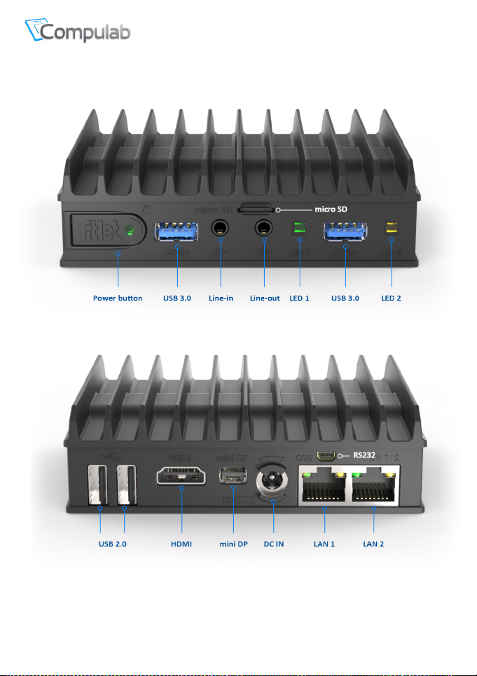
Connectors layout
: +972-48-290-168 |
Hayetsira St. 17, Yokneam, Israel
: +972-48-325-251 |
Page 8

Tel
: +972-48-290-168 |
Fax
www.fit-iot.com
www.fit-iot.com
Page 8 of 18
fitlet2 owner’s manual
Hayetsira St. 17, Yokneam, Israel
: +972-48-325-251 |
Quick start guide
Minimum requirements
To use fitlet2RC you will need:
• RAM and storage device (if not pre-installed)
• A display with HDMI or DisplayPort input + HDMI or mini-DisplayPort cable
• USB keyboard and mouse
Identifying fitlet2RC configuration
fitlet2RC configuration is detailed on the label attached to the bottom side of the computer.
Note
Pay attention to RAM and storage. If not installed fitlet2RC will not boot. You will have to first
install these devices.
Opening fitlet2RC
You will need to open fitlet2RC in order to install RAM, storage and RTC battery.
Required tool: Phillips screwdriver.
Page 9
Tel
: +972-48-290-168 |
Fax
www.fit-iot.com
www.fit-iot.com
Page 9 of 18
fitlet2 owner’s manual
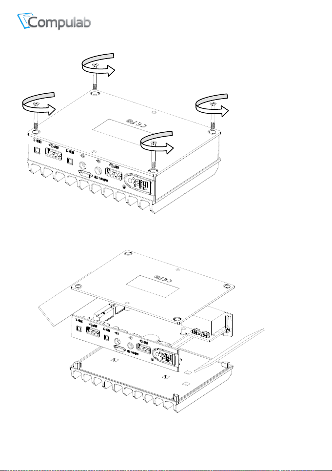
To open fitlet2RC please follow these steps:
Hayetsira St. 17, Yokneam, Israel
: +972-48-325-251 |
1. Place fitlet2RC on a flat surface bottom-up.
2. Open the four screws using the Phillips screwdriver (counter clock-wise).
3. Lift the bottom cover to remove it. Side panels should fall-off.
4. Lift fitlet2RC from the top cover.
Page 10
Tel
: +972-48-290-168 |
Fax
www.fit-iot.com
www.fit-iot.com
Page 10 of 18
fitlet2 owner’s manual
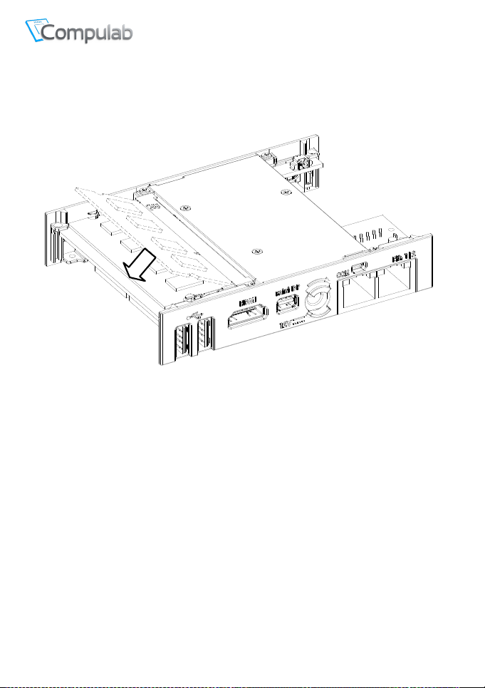
Installing RAM
RAM socket is positioned on the top side of the motherboard.
fitlet2RC accepts a single SODIMM DDR3L (1.35V).
Hayetsira St. 17, Yokneam, Israel
: +972-48-325-251 |
Insert DDR3L SODIMM module and press it down until it is latched firmly on both sides.
Page 11
Tel
: +972-48-290-168 |
Fax
www.fit-iot.com
www.fit-iot.com
Page 11 of 18
fitlet2 owner’s manual
1
2
3
Hayetsira St. 17, Yokneam, Israel
: +972-48-325-251 |
M.2 cooling plate and SSD
The M.2 cooling plate has several purposes:
• Allow installation of multiple form factor M.2 devices and FACET Cards
• Provide cooling to M.2 devices
• Assist in battery placement
• Provide proper cable management inside fitlet2RC
fitlet2RC accepts M.2 M-key 2242 | 2260 SATA SSD.
The SSD has to be fastened to the M.2 cooling plate. Then the M.2 cooling plate is placed at the
underside of the motherboard and fastened to the front and back panel.
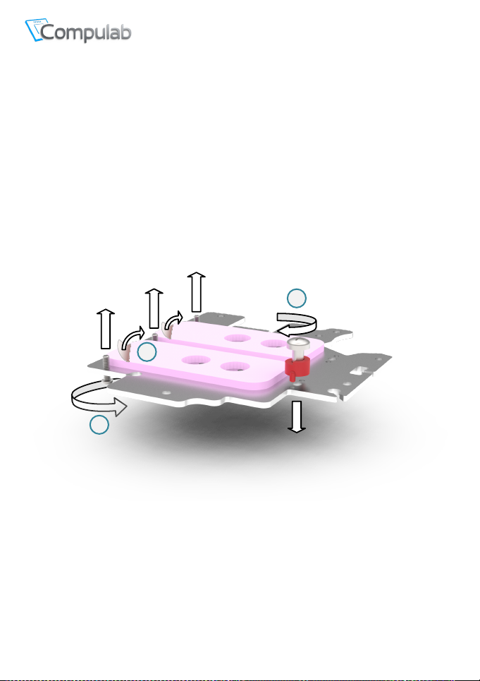
To install SSD onto M.2 cooling plate
1. Screw the 3 alignment screws into the marked holes. These screws are used to position the
M.2 devices
2. Peel-off protective film from the two thermal pads.
3. Place the red M.2 spacer according to the length of the M.2 SSD as depicted below.
Note orientation of the spacer: The recessed side should face the alignment screws.
Insert M.2 fastening screw but do not tighten.
Page 12
Tel
: +972-48-290-168 |
Fax
www.fit-iot.com
www.fit-iot.com
Page 12 of 18
fitlet2 owner’s manual
4
5
6
7
Hayetsira St. 17, Yokneam, Israel
: +972-48-325-251 |
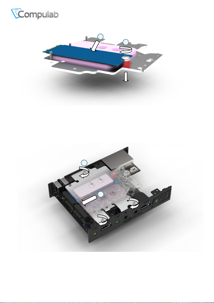
4. Place edge of M.2 SSD against the fastening screw and press the SSD firmly against the
thermal pad until its connector edge is seated between the alignment screws.
Once positioned correctly the connector edge should stick out above the edge of the M.2
cooling plate.
5. Tighten the fastening screw.
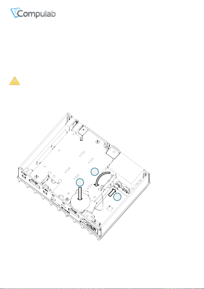
6. Turn over the M.2 cooling plate and push the M.2 SSD into its socket at the underside of the
motherboard.
7. Push down the M.2 cooling plate and tighten the 3 panel screws
Page 13
Tel
: +972-48-290-168 |
Fax
www.fit-iot.com
www.fit-iot.com
Page 13 of 18
fitlet2 owner’s manual
CAUTION: Risk of explosion if battery is replaced by an incorrect type. Replace only
with the same type and manufacturer.
1
2
3
Hayetsira St. 17, Yokneam, Israel
: +972-48-325-251 |
RTC battery
The RTC battery is used for keeping time and date while fitlet2RC is disconnected from power.
BIOS settings and power-up policy is independent of battery. fitlet2RC normally ships with the
battery unplugged to ensure that the battery is not discharged during warehousing.
The battery can keep charge for approx. 5 years when fitlet2RC is disconnected and
significantly longer when fitlet2RC is connected to power. Battery can be purchased separately
to be replaced by the user.
Installing RTC battery
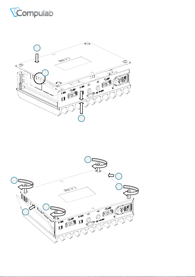
1. Connect the battery plug to the corresponding socket (see illustration).
2. Place the wire as shown inside the slots of the M.2 cooling plate to minimize clutter.
3. Place the battery in the marked pocket. Once fitlet2RC bottom cover is assembled the
battery is secured in place.
Page 14
Tel
: +972-48-290-168 |
Fax
www.fit-iot.com
www.fit-iot.com
Page 14 of 18
fitlet2 owner’s manual
1
2
!
3
3
4
4
4
4
Re-assembling fitlet2RC
Hayetsira St. 17, Yokneam, Israel
: +972-48-325-251 |
1. Place the fitlet2RC onto the top cover.
Note: The top cover is symmetric – direction does not matter.
2. Place the bottom cover onto the fitlet2RC.
Important note: The tall U-shaped boss has to be near the M.2 sockets. Otherwise the
bottom cover will not fit!
3. Click both side panels into place
4. Tighten the 4 screws
Page 15
Tel
: +972-48-290-168 |
Fax
www.fit-iot.com
www.fit-iot.com
Page 15 of 18
fitlet2 owner’s manual
1
2
Connecting fitlet2RC
Hayetsira St. 17, Yokneam, Israel
: +972-48-325-251 |
1. Before connecting fitlet2RC please ensure that RAM and storage device are installed as
detailed in the above sections.
2. Connect the display to fitlet2RC using HDMI or mini-DP cable.
3. Connect to fitlet2RC USB keyboard and mouse.
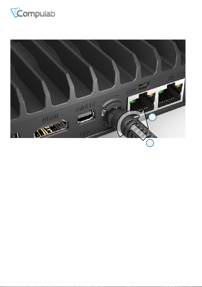
4. Insert the DC plug into the fitlet2RC DC-in jack. Rotate clockwise 90° to secure.
5. Slide into the power-supply the AC blade correct to your country and plug the power-
supply into an AC-outlet. The power button on fitlet2RC should turn green, in a few
seconds an image should appear on the display.
6. Connect Ethernet cable as needed. When link is established the link LED on RJ45 should
light.
7. If fitlet2RC has WiFi adapter installed you will observe two SMA connectors (gold color
screws) on the side panel. Connect the included antennas by screwing them clockwise
onto the SMA connectors to enable WiFi communication.
Page 16

Tel
: +972-48-290-168 |
Fax
www.fit-iot.com
www.fit-iot.com
Page 16 of 18
fitlet2 owner’s manual
Hayetsira St. 17, Yokneam, Israel
: +972-48-325-251 |
Entering BIOS Setup
Turn off the fitlet2RC.
Turn on while holding down the Del key, until access into AMI Inc. BIOS utility.
See http://www.fit-pc.com/wiki/index.php/Main_Page
.
Installing and booting operating system
Please consult https://www.fit-iot.com/web/products/fitlet2rc/os for instructions.
Page 17

Tel
: +972-48-290-168 |
Fax
www.fit-iot.com
www.fit-iot.com
Page 17 of 18
fitlet2 owner’s manual
Hayetsira St. 17, Yokneam, Israel
: +972-48-325-251 |
Service
Support
For technical support and product related questions, please email: [email protected]
For fitlet2RC on support wiki please visit: http://fit-pc.com/wiki/index.php/Fit-
PC_Product_Line:_FITLET2RC
Warranty
• Compulab guarantees products against defects in workmanship and material for a
period of 60 months from the date of shipment.
• Your sole remedy and Compulab’s sole liability shall be for Compulab, at its sole
discretion, to either repair or replace the defective product at no charge.
• This warranty is void if the product has been altered or damaged by accident, misuse
or abuse.
RMA
• Keep the original package for shipping.
• Please contact the seller of that fitlet2RC.
• When issuing an RMA please provide the following required information:
• If fitlet2RC was purchased directly from Compulab, please email: rma@fit-pc.com
o fitlet2RC serial number
o Name and address of buyer
o Invoice number
o Problem description
Page 18
Tel
: +972-48-290-168 |
Fax
www.fit-iot.com
www.fit-iot.com
Page 18 of 18
fitlet2 owner’s manual
fitlet2RC
Statement
WEEE This symbol means that you must dispose of an electrical
Hayetsira St. 17, Yokneam, Israel
: +972-48-325-251 |
Manufacturer: Compulab Ltd.
This device complies with Part 15 of the
FCC Rules.
Operation is subject to the following
two conditions:
(1) This device may not cause harmful
interference, and
(2) This device must accept any
interference received, including
interference that may cause undesired
operation.
Statement
Changes or modifications to this
equipment not expressly approved by
the party responsible for compliance
(Compulab Ltd.) could void the user’s
authority to operate the equipment.
NOTE: This equipment has been tested and found to
comply with the limits for a Class B digital device, pursuant
to part 15 of the FCC Rules. These limits are designed to
provide reasonable protection against harmful interference
in a residential installation. This equipment generates, uses
and can radiate radio frequency energy and, if not installed
and used in accordance with the instructions, may cause
harmful interference to radio communications. However,
there is no guarantee that interference will not occur in a
particular installation. If this equipment does cause harmful
interference to radio or television reception, which can be
determined by turning the equipment off and on, the user
is encouraged to try to correct the interference by one or
more of the following measures:
-Reorient or relocate the receiving antenna.
-Increase the separation between the equipment and
receiver.
-Connect the equipment into an outlet on a circuit different
from that to which the receiver is connected.
-Consult the dealer or an experienced radio/TV technician
for help.
item AND/OR containing in it Li-Mn battery separately from
general household waste when they reach the end of their
useful life. Take your PC or the battery to your local waste
collection point or center. This applies to all countries of
the European Union, and to other countries with a separate
waste collection system.
This symbol means that device is UL listed for use in USA
and Canada and is registered in UL data base under
E510538 number
 Loading...