

Page 1
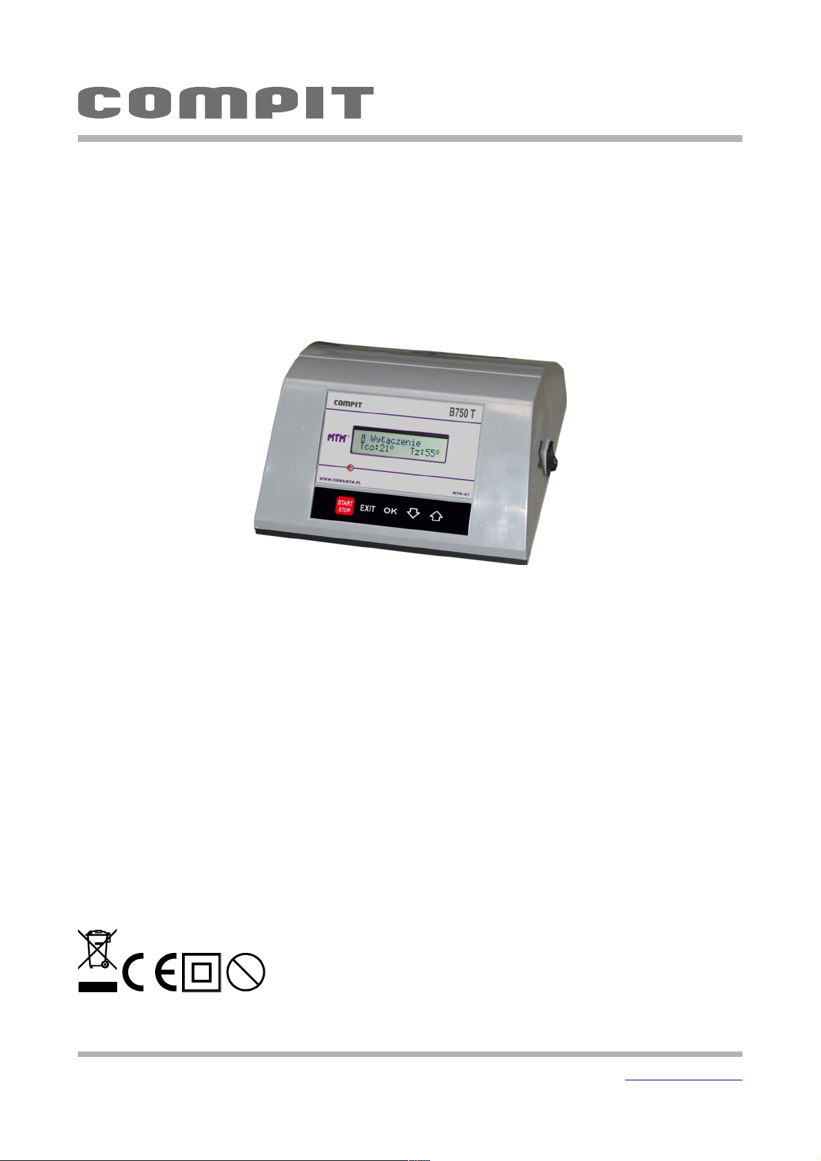
Operating and Installation
Manual
for the u2.00 software version, version 1, 21 February 2017
CONSTANT CONTROLLER OF THE CH BOILER
(GAS/OIL) AND HUW TANK.
Pb
B750 T-1
B750 T-1
COMPIT, ul. Wielkoborska 77, 42-280 Częstochowa, tel.343 62 88 95 www.compit.pl
Page 2

Table of Contents
Description of the controller.........................................................................3
Operation...............................................................................................4
Information Display.................................................................................4
Switching on and off the controller..............................................................5
Setting temperature of the boiler...............................................................5
Setting HUW temperature.........................................................................5
SUMMER mode.......................................................................................6
Advanced Operation...................................................................................6
Restoring factory settings.........................................................................6
Setting parameters.................................................................................6
Service parameters.................................................................................8
Anti-legionella......................................................................................8
Manual operation...................................................................................9
Description of alarm states.......................................................................9
Description of operation............................................................................10
Burner operation..................................................................................10
Working with room thermostat..................................................................10
HUW tank operation..............................................................................10
Assembling.............................................................................................11
General information..............................................................................11
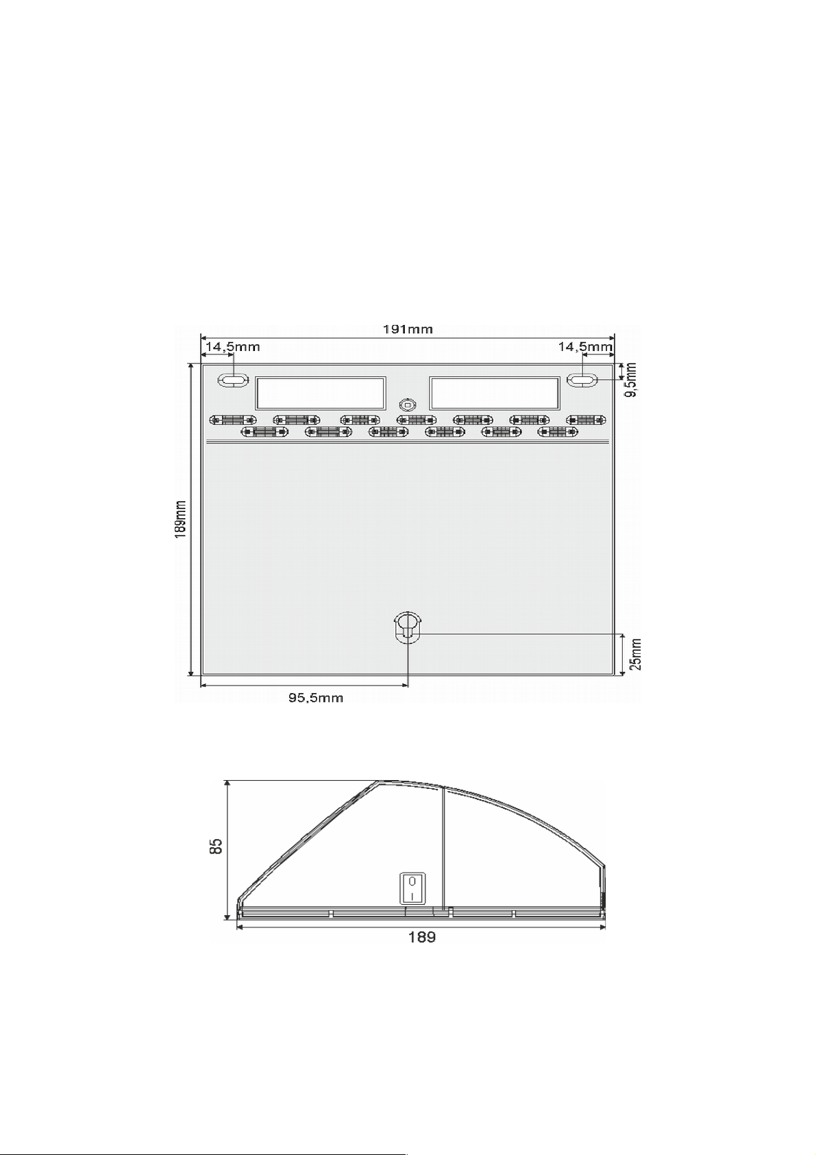
Dimensions of the housing.......................................................................11
Technical data.....................................................................................12
Arrangement of terminals.......................................................................12
Sensors..............................................................................................13
Power supply.......................................................................................13
Room thermostat connection....................................................................14
NANO thermostat connection...................................................................14
2 User manual B750 T u2x, version 1, February 2017
Page 3
Description of the controller
The main task of the controller is to maintain the set temperature of the CH boiler
with single-stage oil or gas burner and to load HUW tank. The controller can operate in
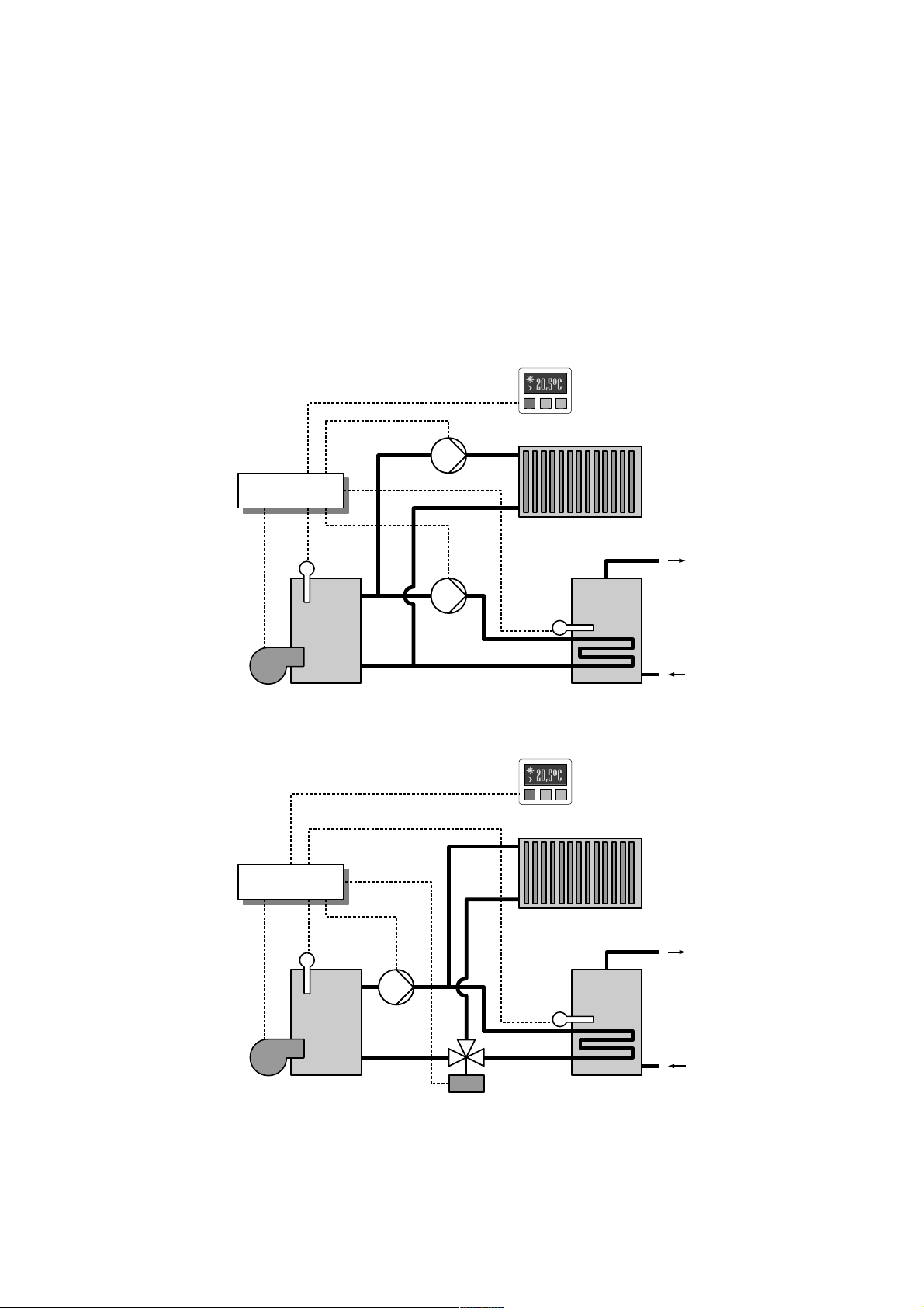
the system with two pumps or circulating pump and distributor. Configuration changes
are made in the "Operating State". The controller operates with room thermostat.
Connection of NANO room thermostat additionally allows monitoring the operation of
the controller.
User manual B750T u2.x, version 1, February 2017 3
B750 T-1
B750 T-1
Boiler
sensor
HUW
sensor
Pump
Room
thermostat
Distributor
B750 T-1
B750 T-1
CH pump
Boiler
sensor
HUW
semsor
HUW
pump
Room
thermostat
Fig 1: Operating State = CH and HUW pumps
Fig 2: Operating State = P.+ DISTRIBUTOR
Page 4
Operation
Information Display
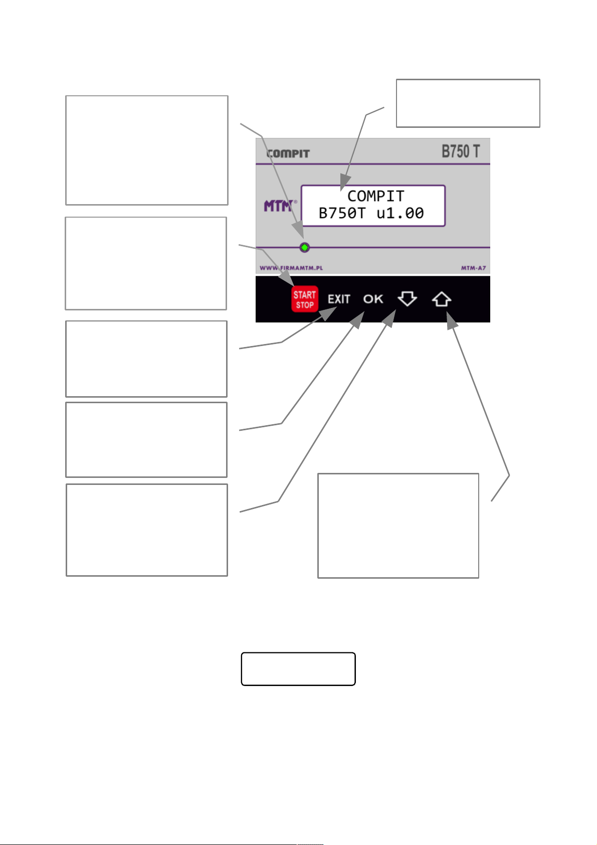
After switching on the controller displays for a moment its name and version number,
for example:
Then it proceeds to display the basic screen that contains a range of information on
the operation of the controller.
4 User manual B750 T u2x, version 1, February 2017
COMPIT
B750T u1.00
LCD display
with backlight.
Mode controls:
Off – lights red
OPERATION – lights green
ALARM – lights alternately
red and green.
START/STOP button:
Switching on. Switching off
- when pressed for 3
seconds. Alarm
acknowledgement.
EXIT button: return to the
home screen.
OK button: viewing
parameters and setting
values.
Down arrow button: moving
on the parameter list or
decreasing the value of the
parameter.
Up arrow button: moving on
the parameter list or
increasing the value of the
parameter.
Page 5
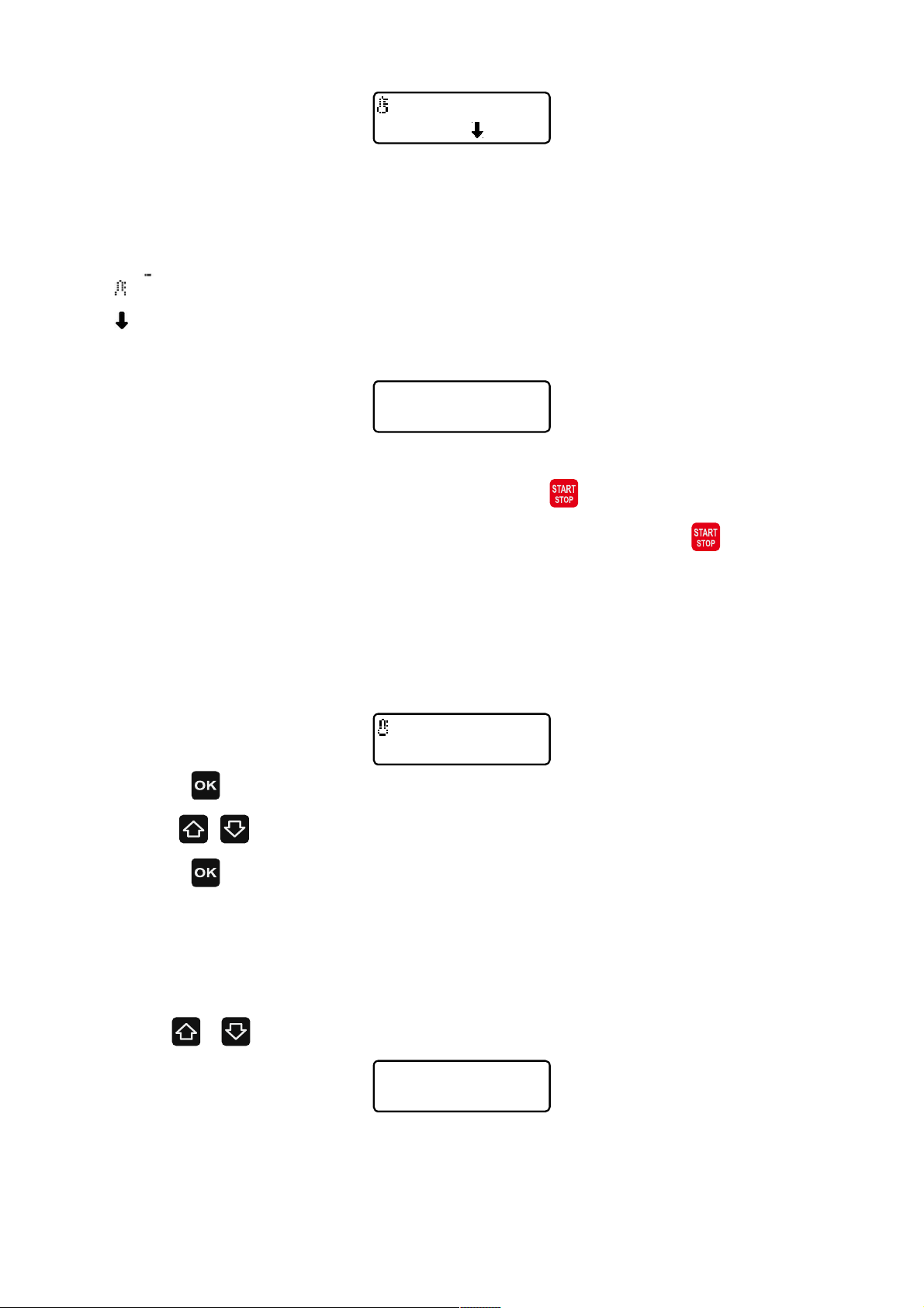
The top line displays information about the activated relays: BUR- burner, CH – CH
pump. HW – HW pump or CH/HUW valve.
Tch:- measured boiler temperature
Ts:- set boiler temperature
- boiler temperature is lower than the temperature of the pump activation.
- decrease from the room thermostat.
The information display in the off mode is shown below:
Switching on and off the controller
If the controller displays Off, then press the button to activate it.
Stopping a running controller can be done by pressing the button for 3 sec. In
"Off" mode, the controller can perform off-season runs, if they are activated in "Off-
season runs" parameter.
Setting temperature of the boiler
1. The preset temperature of the boiler is set on the main screen.
2. Press button, the display shows „?”
3. Use , buttons to set the desired temperature of the boiler
4. Press button, „?” disappears.
Setting HUW temperature
To be able to set the hot water (HUW) it must be switched on in the „HUW
Operation” parameter.
1. Use / buttons to display window of HUW readings
Phw: the state of tank loading pump, 0 = off, 1 = loading the tank (HUW);
Thw: temperature readout in HUW tank;
User manual B750T u2.x, version 1, February 2017 5
Off
Tch:15° Ts:55°
BUR:1 CH:0 HW:0
Tch:15° Ts:55°
BUR:1 CH:0 HW:0
Tch:17 ? Ts:55°
Phw:1 Thw:22°C
♦Thw set: 50°C
Page 6
2. Press button, the display shows „?”
3. With the use of the and buttons set the desired HUW temperature
4. 4. Press button, „?” disappears.
SUMMER mode
SUMMER mode is activated in the parameter with the same name. In the SUMMER
mode central heating pump is turned off, the controller will only load HUW tank.
Advanced Operation
Restoring factory settings
To restore the factory settings of the controller perform the following activities:
1. Set in the „ ACCESS CODE” parameter - value 70
2. Confirm it by pressing button.
3. Press simultaneously , buttons.
4. Entering the factory settings is confirmed by the following information on the
display:
Setting parameters
To change the parameter value perform the following activities:
1. 1. Move to ACCESS CODE
2. Press button. The display shows „?”, this indicates code value editing mode.
3. With the use of and buttons set value 99 for editing the basic parameters
and 199 for editing the service parameters.
4. Press button, „?” disappears
5. With the use of and 5. buttons move to the value readout you want to
change.
6. Press button. Symbol "?" is displayed before the parameter value. This is the
parameter value editing mode.
6 User manual B750 T u2x, version 1, February 2017
FACTORY
SETTINGS
Page 7
7. With the use of and buttons change the parameter value.
8. Exit the edit mode by pressing button. "?" disappears.
, buttons are again used to move on the list of parameters. The code does not
have to be set prior to the change of the next parameter. However, if no controller
button is pressed for 4 minutes, the code is set to 100 and must be reset before the next
edition of the parameter values. Changes of the parameter values are automatically
stored in memory and do not require approval. The settings in the memory are stored
for at least 10 years (controller switched off).
BUR:0 CH:1 HW:0
Tch:56° Ts:55°
PAL: burner, CO: pump CO, CW: HW pump
0- off, 1- on
Tch – CH temperature, Tset – CH set temperature
Thw:49°C
Thw set:50°C
Phw: HW pump
0- off, 1- on
Thw – HW temperature
Thw set – HW set temperature.
SUMMER mode
off
SUMMER mode
off- controller controls CH and HUW pumps
on- CH operation is blocked
ACCESS CODE
100
Access to the other parameters requires setting 99.
Language
POLISH
Language selection
• POLISH
• ENGLISH
HUW Operation
with priority
HUW operation:
• with priority- CH pump is switched off while loading HUW tank.
• parallel with CH – loading HUW tank does not switch off CH
pump
• off - controller does not control loading of HUW tank
Pump activation
Temp. 42°C
Boiler temperature (Tch) above the one at which the controller
may activate the pump.
Setting range: 32..55°C
Thermostat
off
Thermostat:
• off
• on
• NANO 1 – indicates NANO with address 1
• NANO 2 – indicates NANO with address 2
• NANO 3 – indicates NANO with address 3
• NANO 4 – indicates NANO with address 4
• NANO 5 – indicates NANO with address 5
User manual B750T u2.x, version 1, February 2017 7
Page 8
Anti-legionella
NO
Anti-legionella function provides weekly heat sterilization of the
HUW tank. It requires connection of the NANO module.
Boiler hyster.
2°C
Boiler hysteresis. The burner turns on when the boiler set
temperature will decrease below the value set here. It switches
off after reaching the set temperature. Setting range 1..5°C .
HUW loading
hyster. 3°C
HUW loading hysteresis. Loading the HUW tank starts when the
water set temperature falls by the value set here. It ends after
reaching the set temperature. Setting range1..10°C
CH excess to
load HUW 5°C
While loading HUW tank the temperature maintained in the boiler
is higher than the set HUW temperature by the value set in this
parameter. Setting range 0..20°C
Pump run
time 60s
Pumps run provide heat collection accumulated in the boiler body
limiting at the same time increase in temperature of the boiler in
case of reducing the load. Setting range 0..600s.
HUW off with
NANO 1 NO
This parameter determines whether HUW operation is to be
turned off when the user sets for NANO with address 1 HOLIDAY
mode.
Operating state
CH and HUW pumps
Operating state
• CH and HUW PUMPS – system operation with two pumps (Fig. 1)
• P.+ DISTRIBUTOR - system operation with one pump and
distributor CH/HUW (Fig. 2)
Oper. mode RS485
MASTER
RS485 serial interface operating mode. The controller uses the
protocol C14. One controller in such a network must be in MASTER
mode. Others must operate in SLAVE mode.
ADDRESS in NET
1
Controller address in the net. Two controllers of the same class
cannot have the same address.
Off-season
runs on
Off-season runs protect pumps against blocking due to deposition
in them sediments and contaminants. They consist of switching
CH and HUW pumps every 3 days for 15 seconds.
Service parameters
Service parameters are available with code 199.
Max. boiler
set temp. 85°C
Maximal boiler set temperature.
Setting range 80..95°C .
Min. boiler
set temp. 40°C
Minimalna temperatura zadana kotła.
Setting range 30..80°C .
Anti-legionella
Anti-legionella function must be activated in „Antilegionella” parameter. Sterilization
is carried out by trying to increase the temperature of the HUW tank to 72°C. The
controller does this every week.
8 User manual B750 T u2x, version 1, February 2017
Page 9
Manual operation
Manual mode lets you easily test the operation of the controller outputs and proper
connection. To enter the manual operation, turn off the controller using the power
switch. Press and buttons and then switch on the power. After a while on the
display appears:
CH:23° – measured boiler temperature, /P:1 CH pump operation
BUR:0 burner operation, CW:15° - measured HUW tank temperature, /P:0 – HUW
pump operation
Meaning of buttons:
- On / off CH pump
- On / off HUW pump
- On / off burner
- Finish manual operation.
Description of alarm states
The controller displays information about recognized alarm state, which prevents
normal operation of the boiler. This is signaled by the changing color of the indicator and
activation of the buzzer. Boiler operation is stopped.
E01 Tch>Talarm
Tch:99° Ts:55°
The boiler temperature exceeded 95°C. Alarm is activated after
60 seconds.
E08 Damaged SEN.
Tch:##° Ts:55°
Boiler temperature sensor damage. The alarm is signaled if the
measured temperature exceeds the measuring range of the
controller (-9 .. +109 °C).
If the alarm cause was resolved, the alarm state can be reset by pressing
User manual B750T u2.x, version 1, February 2017 9
TEST CH:23°/P:1
BUR:0 HW:15°?P:0
Page 10

Description of operation
Burner operation
Boiler burner is activated when the boiler temperature drops one degree below the
set point minus the boiler hysteresis. The burner is switched off when the boiler set
temperature is reached. For example, if the set temperature = 55°C, and hysteresis =
3°C, the burner turns on at boiler temperature 51°C and turns off at temperature
55°C .
Working with room thermostat
Cooperation with room thermostat helps to maintain the proper temperature in the
heated rooms. This also affects the fuel savings. Room thermostat operation is turned on
in the „Thermostat” parameter.
When the room temperature reaches the value set on the thermostat, information
about this fact reaches the controller and is indicated by the arrow symbol that appears
on the main screen. The controller turns off the burner, CH pump is turned off with a
delay that is specified in the „Pumps run time”.
HUW tank operation
HUW tank operation can be activated in "HUW operation" parameter. You can choose
to work in parallel with CH or HUW priority – then while loading HUW tank CH pump is
turned off.
The tank is loaded, if its temperature drops one degree below the set value minus
the value of the parameter "HUW loading hysteresis". If necessary, the controller
increases the boiler set temperature by the value set in parameter "CH excess to load
HUW" above the HUW set temperature. HUW pump is switched on when the boiler
temperature is sufficiently higher than the tank temperature; such action prevents
cooling of the tank by the boiler. Loading ends after reaching the tank set temperature.
The loading pump continues to run for time set in parameter "Pump run time" to safely
distribute heat accumulated in the boiler while loading the HUW tank. The run time can
be automatically shortened if the temperature of the boiler permits it.
10 User manual B750 T u2x, version 1, February 2017
Page 11
Assembling
General information
Connection and installation works should be performed only by a person with
appropriate qualifications and permissions in accordance with the applicable regulations
and standards. All connection work can take place only when the power supply is
disconnected; make sure that the electrical wires are not energized
Dimensions of the housing
User manual B750T u2.x, version 1, February 2017 11
Fig 3: The dimensions of the controller base.
Fig 4: The dimensions of the controller side.
Page 12

Technical data
Power supply: 230V, 50Hz
Power consumed by the controller 4W
Maximum rated current: Burner rely 16 (8)A
CH pump: 4(2)A
HUW pump: 4(2)A
Fuses: 4A / 250V (characteristics F– fast)
Controller protection: IP20
Ambient temperature: 0..55°C
Storage temperature: 0..55°C
Relative humidity: 5 – 80% no condensation
Sensor type T2001
Measurement range: -9..109°C
Temp. measurement accuracy: ±2°C
Connections: 1,5mm
2
Display: LCD text
Dimensions: 191 x 189 x 85 mm
Weight 0,5kg
Communication protocol: C14
Arrangement of terminals
12 User manual B750 T u2x, version 1, February 2017
HUW sensor
L N
ZAS
L N
PCO
L N
PCW
T1 T2
PAL
U G B A
M
1~
M
1~
MAINS
230V~
CH
pump
HUW
pump
Burner
1
T
CO
2
T
CWU
3
T
TER
Fuses
2 x 4A F
Room
thermostat
Boiler sensor
Connector
to NANO
Page 13

Sensors
The controller works with sensors type T2001.
T2001 sensors consist of a measuring element placed in a stainless steel casing having
a diameter of 6 mm and a wire resistant to temperatures up to 100°C. The sensor cable
can be extended with a wire with cross section of not less than 0,5mm², the total cable
length should not exceed 30m. The sensors are not hermetic, and therefore it is
prohibited to immerse them in any liquid.
T2001 sensors are not interchangeable with other types of sensors, for example
T1001, T1002, T1401!
The boiler temperature sensor must be mounted in a thermowell tube placed in the
boiler shell. HUW tank temperature sensor (if any) should be placed in the tank
thermowell tube. Ensure good thermal contact between the sensor and the surface
measured. If necessary, use the thermal paste. The sensor cables cannot come into
contact with surfaces whose temperature can be higher than 100°C. The minimum
distance between the sensor cables and parallel mains wires is 30cm. A smaller distance
can cause instability of temperature readings.
Temperature Resistance Temperature Resistance
[°C] [Ω] [°C] [Ω]
0 1630 60 2597
10 1722 70 2785
20 1922 80 2980
30 2080 90 3182
40 2245 100 3392
50 2417 110 3607
Table 1: Resistance values of the T2001 sensor for selected temperatures.
Power supply
The controller must be powered from an electrical installation with a voltage of 230V /
50Hz. Installation should be three-wire, protected by RCD and overcurrent fuse with a
value chosen to load and wire cross-sections. Connecting cables must be routed in such a
way as not to come into contact with surfaces of temperature exceeding their nominal
operating temperature. The wire ends must be protected with clamp sleeves. Controller
screw terminals allow connecting a cable with a maximum cross-section of 1,5mm².
User manual B750T u2.x, version 1, February 2017 13
Page 14
Room thermostat connection
The room thermostat must be connected to the terminals marked TER in the
controller. These terminals are visible after removing the back cover of the controller.
The thermostat may not apply any voltage to the controller! It must apply ON / OFF
signal (contacts closed / contacts closed). The room thermostat should be installed in a
room representative of the whole heated building, away from heat sources and the
doors and windows, at a height of 1.2 - 1.7 m above the floor. After connecting the room
thermostat it must activated in „Thermostat” parameter.
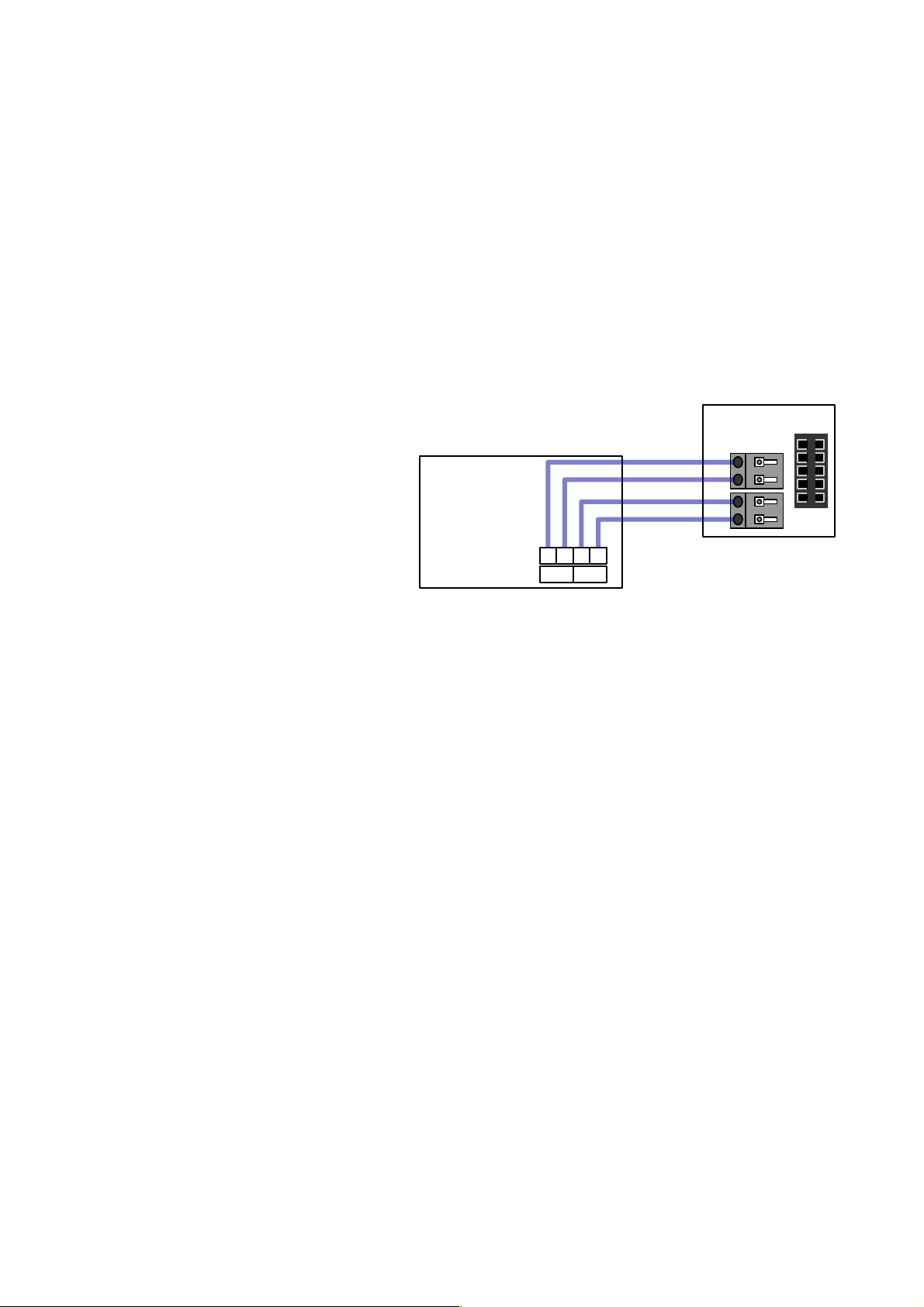
NANO thermostat connection
NANO should be connected to the
appropriate terminals marked „RS485
U-G-B-A” via a 4-wire cable with a
cross section 0,25mm2 according to
the diagram.
In order to set operation between
heating circuit and NANO it must be configured by selecting the thermostat number with
which the controller operates in the "Thermostat" parameter.
14 User manual B750 T u2x, version 1, February 2017
U G B A
Connection
to NANO
B750 T-1
NANO one
connection
U
G
B1
A1
 Loading...