

Page 1
wireless modules
2.4GHz/5GHz WiFi + Bluetooth Combination Module
Designed for WLAN/BT and Low-Energy Communications
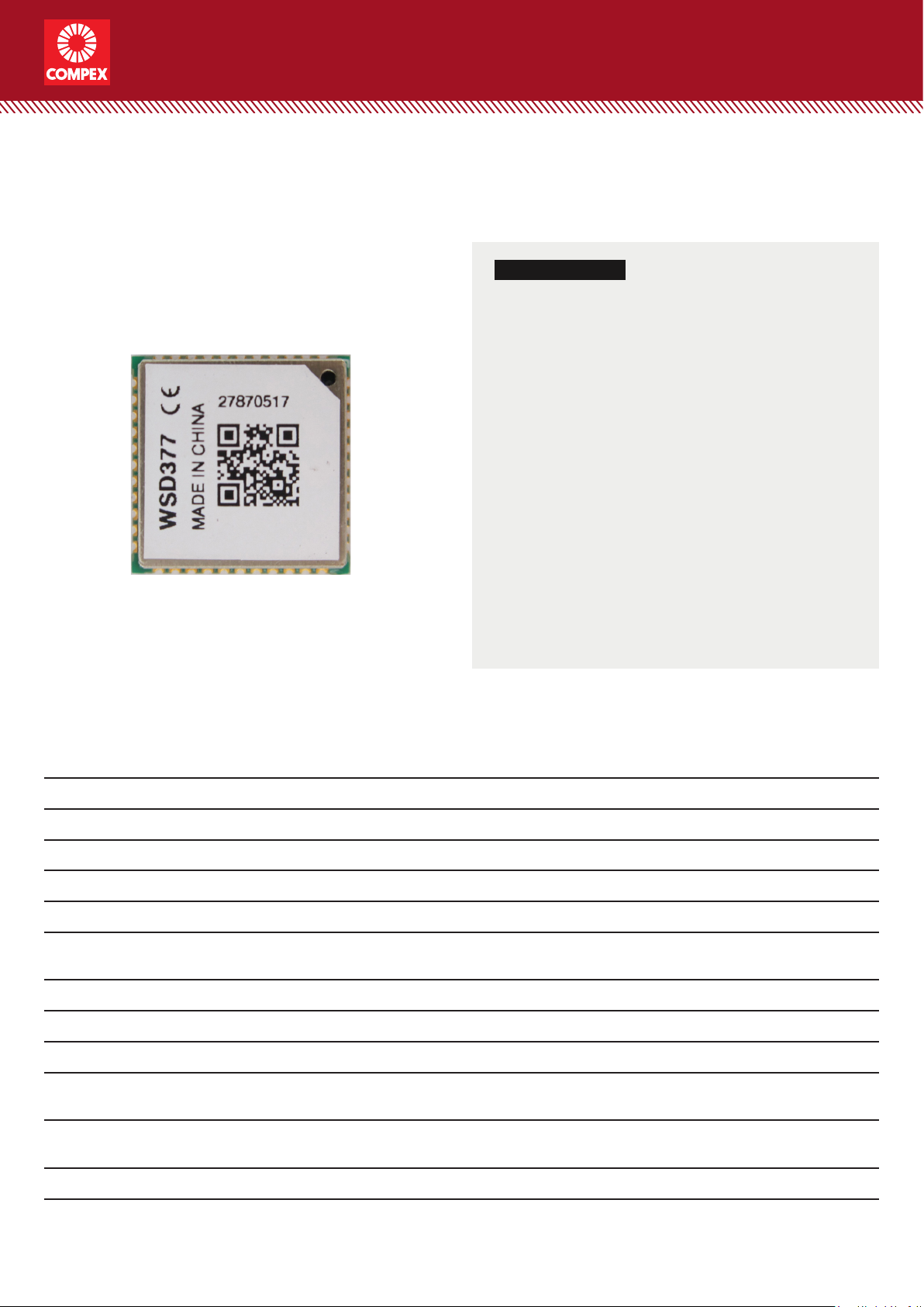
Model: WSD377
KEY FEATURES
• Qualcomm Atheros QCA9377
• Single-die wireless local area network (WLAN)
and Bluetooth (BT) combination solution
• Supports 1x1 IEEE 802.11b/g/n at 2.4GHz
• Supports 1x1 IEEE 802.11a/n/ac at 5GHz
• Provides a highly integrated WLAN system-on-
chip (SoC) for 5 GHz 802.11ac, or 2.4 GHz/5 GHz
802.11n WLAN applications
• Supports Bluetooth 4.2 + HS single mode
with backward compatibility for BT 1.x, BT 2.x,
BT4.2 + Enhanced Data Rate
• Supports 20/40MHz at 2.4GHz and supports
20/40/80MHz at 5GHz
• Supports multiuser MIMO
• Supports BT-WLAN coexistence and ISM-LTE
coexistence
• Supports IEEE 802.11d, e, h, i, k, r, v, and w
• Supports Client Dynamic Frequency Selection (DFS)
Specications
Chipset QCA9377
Device Variant QCA9377-3
System Memory OTP
WLAN Host Interface Low-power SDIO 3.0
Bluetooth Host Interface UART/PCM
Operating Voltage 3.3V DC power supply and I/O supply of 1.8V or 3.3V
WLAN Frequency Range 2.412GHz to 2.462GHz
5.180GHz to 5.825GHz
Bluetooth Frequency Range 2.402GHz to 2.480GHz
Power Consumption 3.83W (Max)
Modulation Techniques CCK, OFDM: BPSK, QPSK, 16-QAM, 64-QAM, 256-QAM
Temperature Range Operating: -20°C to 70°C
Storage: -40°C to 90°C
Humidity Operating: 5% to 95% (non-condensing)
Storage: Max. 90% (non-condensing)
Dimensions (W x H x D) in mm 12 x 12 x 2.5
Last Updated: 31/10/18
Page 2
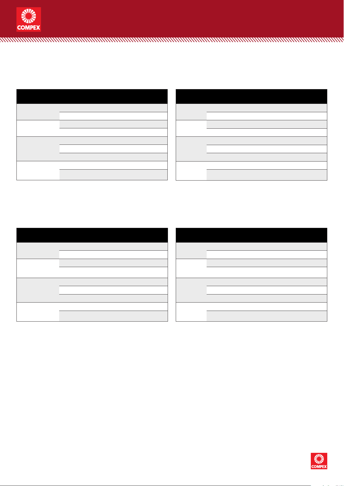
RF Performance Table for 2.4GHz
wireless modules
Data Rate TX Power Tolerance
2.4GHz
802.11b
2.4GHz
802.11g
2.4GHz
802.11n
20MHz
2.4GHz
802.11n
40MHz
1Mbps 16dBm ±2dB
11Mbps 16dBm ±2dB
6Mbps 15dBm ±2dB
54Mbps 13dBm ±2dB
MCS 0 14dBm ±2dB
MCS 7 13dBm ±2dB
MCS 8 13dBm ±2dB
MCS 0 14dBm ±2dB
MCS 9 13dBm ±2dB
RF Performance Table for 5GHz
Data Rate TX Power Tolerance
5GHz
802.11a
5GHz
802.11n/ac
20MHz
5GHz
802.11n/ac
40MHz
5GHz
802.11n/ac
80MHz
6Mbps 11dBm ±2dB
54Mbps 10dBm ±2dB
MCS 0 11dBm ±2dB
MCS 7 7dBm ±2dB
MCS 0 10dBm ±2dB
MCS 7 6dBm ±2dB
MCS 8 6dBm ±2dB
MCS 0 9dBm ±2dB
MCS 9 6dBm ±2dB
2.4GHz
802.11b
2.4GHz
802.11g
2.4GHz
802.11n
20MHz
2.4GHz
802.11n
40MHz
5GHz
802.11a
5GHz
802.11n/ac
20MHz
5GHz
802.11n/ac
40MHz
5GHz
802.11n/ac
80MHz
Data Rate
1Mbps -97dBm ±2dB
11Mbps -90dBm ±2dB
6Mbps -92dBm ±2dB
54Mbps -76dBm ±2dB
MCS 0 -92dBm ±2dB
MCS 7 -75dBm ±2dB
MCS 8 -71dBm ±2dB
MCS 0 -89dBm ±2dB
MCS 9 -67dBm ±2dB
Data Rate
6Mbps -92dBm ±2dB
54Mbps -75dBm ±2dB
MCS 0 -92dBm ±2dB
MCS 7 -74dBm ±2dB
MCS 0 -89dBm ±2dB
MCS 7 -72dBm ±2dB
MCS 8 -70dBm ±2dB
MCS 0 -86dBm ±2dB
MCS 9 -62dBm ±2dB
RX Specifications
Sensitivity
RX Specifications
Sensitivity
Tolerance
Tolerance
Copyright © Compex Systems. All rights reser ved. COMPEX and the COMPE X logo, are registered trademarks of Compex Inc.
2
Atheros and other trademarks are properties of their respective owners. While every ef fort is made to ensure the information is accurate,
Compex does not accept liability for any errors or mistakes that may arise. All specifications are subject to change without notice.
Compex Systems Pte Ltd | www.compex.com.sg | (+65) 6286 2086 | sales@compex.com.sg | Last Updated: 31/10/18 WH XG HB
Page 3
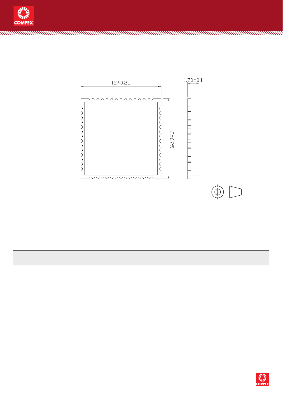
Dimensional Drawing
wireless modules
Ordering Conguration
Item Code Model Description
WSD377 7A0000-R1.02 WSD377 802.11a/b/g/n/ac 1x1 WiFi+BT, SDIO+UART
All dimensions are in mm.
Copyright © Compex Systems. All rights reser ved. COMPEX and the COMPE X logo, are registered trademarks of Compex Inc.
3
Atheros and other trademarks are properties of their respective owners. While every ef fort is made to ensure the information is accurate,
Compex does not accept liability for any errors or mistakes that may arise. All specifications are subject to change without notice.
Compex Systems Pte Ltd | www.compex.com.sg | (+65) 6286 2086 | sales@compex.com.sg | Last Updated: 31/10/18 WH XG HB
Page 4

wireless modules
To facilitate the antenna tuning and certification test, a RF connector and an antenna
matching circuit should be added. The following figure is the recommended circuit.RF
trace should be 50Ω.
Antenna matching peripheral circuit schematic
4
Page 5

Antenna matching peripheral circuit PCB layout
wireless modules
The C90 are 0Ω resistors, and the C6, C9 are reserved for tuning and have no
components. The RF test connector is used for the conducted RF performance test,
and should be placed as close as to the module’s MAIN_ANT pin. The traces impedance
between WSD377 and antenna must be controlled in 50Ω.
EUT sample plot
Note:All platforms must follow this antenna matchingwhen using this module. If not follow
completely, the FCC authorization is no longer considered valid.
5
Page 6

wireless modules
Compliance Information
This device complies with Part 15 of the FCC Rules. Operation is subject to
the following two conditions:
1. This device may not cause harmful interference, and
2. This device must accept any interference received, including interference
that may cause undesired operation.
FCC Statement:
This equipment has been tested and found to comply with the limits for a Class
B digital device, pursuant to part 15 of the FCC Rules. These limits are
designed to provide reasonable protection against harmful interference in a
residential installation. This equipment generate, uses and can radiate radio
frequency energy and, if not installed and used in accordance with the
instructions, may cause harmful interference to radio communications.
However, there is no guarantee that interference will not occur in a particular
installation. If this equipment does cause harmful interference to radio or
television reception, which can be determined by turning the equipment off and
on, the user is encouraged to try to correct the interference by one or more of
the following measures:
- Reorient or relocate the receiving antenna.
- Increase the separation between the equipment and receiver.
- Connect the equipment into an outlet on a circuit different from that to
which the receiver is connected.
- Consult the dealer or an experienced radio/TV technician for help.
Any changes or modifications not expressly approved by the party responsible
for compliance could void the user's authority to operate the equipment.
Exposure to Radio Frequency Radiation. This equipment must be installed and
operated in accordance with provided instructions and the antenna(s) used for
this transmitter must be installed to provide a separation distance of at least 20
cm from all persons and must not be collocated or operating in conjunction
with any other antenna or transmitter.
End-users and installers must be provided with antenna installation
instructions and transmitter operating conditions for satisfying RF exposure
compliance.
6
Copyright © Compex Systems. All rights reser ved. COMPEX and the COMPE X logo, are registered trademarks of Compex Inc.
Atheros and other trademarks are properties of their respective owners. While every ef fort is made to ensure the information is accurate,
Compex does not accept liability for any errors or mistakes that may arise. All specifications are subject to change without notice.
Compex Systems Pte Ltd | www.compex.com.sg | (+65) 6286 2086 | sales@compex.com.sg | Last Updated: 31/10/18 WH XG HB
Page 7

wireless modules
For end product label, the final end product must be labeled in a visible area
with the following: “Contains Transmitter Module FCC ID: TK4WSD377 or
Contains FCC ID: TK4WSD377”
Note:
(1) This device is approved for OEM installation with specified antennas as
listed in this Manual. It is the responsibility of the Installer to comply with the
separation distance for satisfying RF exposure compliance.
(2) This device only could work when being installed into “client devices” which
could not transmit automatically.
Important Note: In the event that these conditions can not be met (for example
certain laptop configurations or co-location with another transmitter), then the
FCC authorization is no longer considered valid and the FCC ID can not be
used on the final product. In these circumstances, the OEM integrator will be
responsible for re-evaluating the end product (including the transmitter) and
obtaining a separate FCC authorization.
Antenna Type Frequency Band (MHz) TX Paths Antenna Gain (dBi)
Dipole Antenna
OEM installation must use the antenna that its antenna gain less than above table gain.
2400 ~ 2483.5 1*1 5.0
5150 ~ 5850 1*1 7.0
Copyright © Compex Systems. All rights reser ved. COMPEX and the COMPE X logo, are registered trademarks of Compex Inc.
7
Atheros and other trademarks are properties of their respective owners. While every ef fort is made to ensure the information is accurate,
Compex does not accept liability for any errors or mistakes that may arise. All specifications are subject to change without notice.
Compex Systems Pte Ltd | www.compex.com.sg | (+65) 6286 2086 | sales@compex.com.sg | Last Updated: 31/10/18 WH XG HB
 Loading...