

Page 1

IWAVEPORT
WLM54GP30-ESD
USER MANUAL
Page 2

© Copyright 2007 Compex Systems Pte Ltd
All Rights Reserved
This docume nt contains information, which is protected by copyright.
Reproduction, adaptation or tra nslation without p rior pe rmission is p rohibited,
except as allowed under the copyright laws.
Trademark Information
Compex® is a regi stered t rademarks o f Co mpex, Inc. Mic rosoft Windows an d
the W indows l ogo are th e tr ademarks of Microsoft Corp. NetWare is th e
registered tr ademark of N ovell I nc. All oth er br and an d pro duct n ames ar e
trademarks or registered trademarks of their respective owners.
Notice: Cop yrights © 2007 by Comp ex, Inc . Al l rig hts re served. Rep roduction,
adaptation, or translation without prior permission of Compex, Inc. is prohibited,
except as allowed under the copyright laws.
Manual Revision by Daniel
Manual Number: U-0539-V1.8C Version 1.8, May 2007
Disclaimer
Compex, Inc. p rovides this ma nual with out warranty o f any kind, expressed or
implied, in cluding but not limit ed to th e im plied w arranties of m erchantability
and fitn ess fo r a particuar prpose. Compex, I
and/or changes to
in this maual, without prior notice.
technical in
periodically made to
incorporated into later
ject to change without prior notice.
sub
accuracies or typographical errors found in this guide. Changes are
the p roduct and/or specifications of the product described
C ompex, Inc will not be liable for any
the information contained herein and will be
versions of the manual. The information contained is
nc. may mak e improvements
Your Feedback
We value your feedback. If you find any errors in this user’s manual, or if you
have suggestions on improving, we would like to hear from you. Please contact
us at:
Fax: (65)
Email:
62809947
feedback@compex.com.sg
Page 3

FCC NOTICE
This device h as bee n tested a nd found to comply with the limits fo r a C lass B
digital device, pursuant to Part 15 of the FCC Rules. These limits are designed to
provide re asonable protection ag ainst harmful interfe rence in a re sidential
installation. Thi s devi ce g enerates, uses and c an r adiate r adio fr equency
energy and, if no t i nstalled and u sed i n accordance with the instructions, may
cause h armful inter ference to ra dio c ommunications. Ho wever, th ere is n o
guarantee th at i nterference will not occur in a particul ar instal lation. I f thi s
device do es cause harmf ul inte rference to radio or television recep tion, th e
user is encouraged to try to correct the in terference by one or more of the
following measures:
• Reorient or relocate the receiving antenna.
• Connect the comp uter in to an outlet on a ci rcuit d ifferent from that to
which the receiver is connected.
•
Increase the separation between the computer and receiver.
•
Consult the dealer or an experienced radio/TV technician for help.
Caution
of this device could void the user's authority to operate the equipment.
FCC Compliance Statement:
Operation is subject to the following two conditions:
1. This device may not cause harmful interference, and
2. This de vice must acc ept an y in terference rec eived, incl uding interfere nce
This device must accept any interference received, including interference that
may cause undesired operation.
Caution:
This equipment must be installed and operated in accordance with provided
instructions and the antenna(s) used for this transmitter must be installed to provide
a separation distance of at least 20 cm from all persons and must not be co-located
or operating in conjunction with any other antenna or transmitter. End-users and
installers must be provide with antenna installation instructions and transmitter
operating conditions for satisfying RF exposure compliance.
: Any changes or m odifications not e xpressly approved by the grantee
This device complies with Part 15 of the FCC Rules.
that may cause undesired operation.
Expos
ure to Radio Frequency Radiation.
Page 4

Page 5

End Product Labeling
The fi nal en d p roduct must b
e labeled i n a visible ar ea w ith the
following:
ICES 003 Statement
This Class B digital apparatus complies with Canadian ICES-003.
“Contains FCC ID: TK4-WLM54GP30ESD”
Declaration of Conformity
Compex, Inc. declares the following:
Product Name: Compex Wireless Mini-PCI Network Adapter
Model N o.: Co mpex iW avePort
Product Standards:
Radiated Emission Standards:
ETSI EN 300 328-2: July 2000; FC C: 47 CFR Pa rt 15, Subpart B, ANSI C63.4-1992; 47
CFR Part 15, Subpart C (Section 15.247), ANSI C63.4-1992.
Conducted Emission Standards:
ETS 300 826: Nov. 1997.
Immunity Standards:
IEC 801-2; IEC 801-3; IEC 801-4
Low Voltage Directive:
EN 60 950:1992+A1: 1993+A2: 1993+A3; 1995+A4; 1996+A11: 1997
Therefore, this product is in conformity with the following regional standards:
FCC Class B ⎯ f ollowing the pro visions of FCC P art 1 5 directive; CE Mark ⎯
following the provisions of the EC directive.
This Class B digital apparatus complies with Canadian ICES-003.
WLM54GP30-ESD c onforms to the foll owing
Technical Support Information
The w arranty i nformation an d regis tration f orm ar e found i n th e Quic k I nstall
Guide.
For t echnical supp ort, you may con tact Compex o r its su bsidiaries. Fo r you r
convenience, you may also seek technical assistance from the local distributor,
or f rom the autho rized d ealer/reseller that you have p urchased this p roduct
from. For technical support by email, write to support@compex.com.sg.
Refer to the table below for the nearest Technical Support Centers:
Page 6
Write
Call
Fax
Write
Call
Fax
Internet
access/
Website:
Technical Support Centers
Contact the technical support center that services your location.
U.S.A., Canada, Latin America and South America
Compex, Inc.
840 Columbia Street, Suite B,
Brea, CA92821, USA
Tel:
Tel:
Fax:
+1 (714) 482-0333 (8 a.m.-5 p.m. Pacific time)
+1 (800) 279-8891 (Ext.122 Technical Support)
+1 (714) 482-0332
Asia, Australia, New Zealand, Middle East and the rest of the World
Compex Systems Pte Ltd
135, Joo Seng Road #08-01, PM Industrial Building
Singapore 368363
Tel:
Tel:
Fax:
E-mail:
FTPsite:
http://www.cpx.com
(65) 6286-1805 (8 a.m.-5 p.m. local time)
(65) 6286-2086 (Ext.199 Technical Support)
(65) 6283-8337
support@compex.com.sg
Ftp.compex.com.sg
or
http://www.compex.com.sg
Product Overview
·
Introduction
Thank y ou f or p urchasing t his Wireless Network Adapter. Data security is
facilitated with WPA, IE EE 80 2.1x Authe ntication and 64-b it, 128-bi t and 152-bit
WEP (W ired Eq uivalent Priva cy). The y s upport e asy Plug an d Play installa tion
and combine simplicity, data privacy, and reliability for your wireless network.
Chapter 1 Basic Setup
This chapter outlines the basic requirement for the installation and configuration
of the network adapter.
This network adapter is a plug-and-play device. You can plug it into the PCI slot
of your PC for auto-detection.
1.1 H ardware Installation
Page 7
1. Turn off your PC and switch off the pow er from th e m ain pow er
supply.
2. R emove the back cover of the PC.
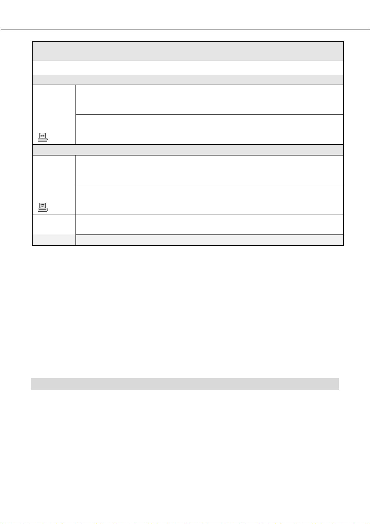
3. Then i nsert the network ad apter i nto you r P CI slot as s hown below.
Ensure that the network adapter is properly seated into the slot.
4. Replace the back cover.
5. Power on your PC.
WLM54AG
PCI slot
Page 8

1.2 D river & Utility Installation
1. Insert the Product CD into your computer CD-ROM drive.
2. Click on Driver & Utility section and the sy stem will run the
automatically.
3. N ext, the
on the Next> button to proceed.
Atheros Client Installation Program
setup.exe
screen appea rs. Cl ick
4. When th e L icense Agreement s creen appears, you are r equired t o
read an d accept th e agreement to c ontinue. Clic k o n th e
button to proceed.
Next>
Page 9
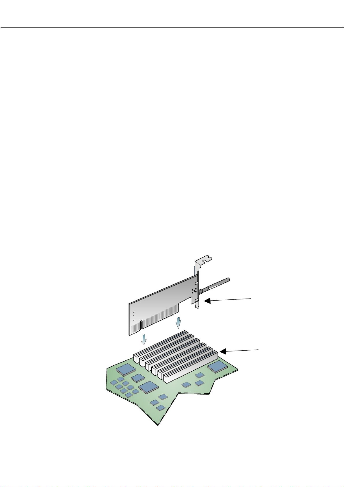
5. Select your preferred setup:
Install Client Utilities and Driver (Recommended) option
You a re r ecommended to sel ect this setup ty pe. This op tion wi ll
install both the driver and utility that support your PCI adapter.
Install Driver Only option (For Windows XP user only)
Select th is op tion if y ou are going to u se the W ireless Zero
Configuration U tility to configure yo ur PCI a dapter. Note t hat only
Windows XP comes with the Wireless Zero Configuration Utility.
Make Driver Installation Diskette(s)
Select this option if you wish to make a duplicate copy of the driver
and store to the diskette/s.
6. Click o n the
screen.
Next>
b utton and f ollow the instr uctions st ated on the
Page 10

For Windows XP users
7. If y ou a re us ing W indows XP as op erating sy stem, t he f ollowing
screen will appear. Read the notice carefully and click on the
button to proceed.
8. Select your ch oice of tool to a ssist you i n configuring y our ad apter.
Click on the Next> button to proceed.
Next>
Atheros Client Utility (ACU) and Supplicant option
Select this option to install your network adapter. (Recommended)
Third Party Supplicant option
Select this option if you decide to u se Wireless Zero Configuration
Utility to configure your wire less device. I nstalling th is t ool w ill o nly
allow you to view the status of the connec ted wire less device/ s
through the utility; configuration using the utility will not be allowed.
Page 11

If y ou ha ve se lected Third Party Supplicant configuration tool, a
screen similar to tha t be low will ap pear, p rompting y ou to
enable/disable the system tray icon.
9. Click on th e c heckbox bes ides
Enable Atheros System Tray Utility
and cl ick on the
Next>
b utton to
proceed.
10. The s creen below appears to i nform y ou th at th e driver w ill b e
automatically install ed if you have already inse rted y our cl ient
adapter into the PCI slot of your computer.
Cancel the Found New Hardware Wizard if i t appears and c lick on
the OK button to begin the installation.
11. If a similar screen similar to th e one shown b elow app ears, cl ick on
the Continue Anyway button to continue the installation.
Page 12

12. Click on the OK button to rebo ot your system and this w ill complete
the installation.
Chapter 2 Using the System Tray Utility
This ch apter w ill elaborate on the Atheros sy stem
tray utility fou nd at th e rig ht b ottom co rner of you r
screen. Right click on the utility icon and the menu
will appear.
The following explains the different options available on the menu:
Page 13

Help
Open the online help.
Exit
Exit the Atheros Client Utility application. Once you exit, the icon will disa ppear
from the system tray.
Open Atheros Client Utility…
Launch the Client Utility.
Wireless-G Excellent Signal Strength Example
Different signal strength indications
Wireless-AG No Link Example
Manual LEAP Login
If you select this option, you will have to manually start the LEAP authentication
process to login to the n etwork instea d of b eing prompted f or y our LE AP
username and password during your windows logon.
Page 14

Reauthenticate
Reauthenticate to a L EAP-configured a ccess point each tim e you l ogin to a
LEAP network.
Select Profile
Click on a configuration profile name to switch to a particular wireless n etwork.
If no configuration profile exists, you will need to add a profile first.
Connection Status
To view the connection status of your wireless PCI adapter.
Alternatively, you may also double click on the utility icon in the system tray.
Active Profile Displays the name of the active configuration profile.
Auto Profile Selection Shows whether auto profile selection is enabled.
Connection Status
Displays whether the adapter is connected to a
wireless network.
Page 15

Link Quality States the quality of the link connection.
Displays the SSID of the network to which the
SSID
network adapter is associated.
Access Point Name
Access Point IP Address
Current Receive Rate Displays the data rate at which the wireless adapter
Current Transmit Rate
Link Speed
Client Adapter IP Address Displays the IP address of the wireless adapter.
States the speed of the link connection.
Shows the name of the access point the wireless
adapter is connected to (if any).
Shows the IP address of the access point the wireless
adapter is connected to (if any).
is currently receiving from the wireless network.
Displays the data rate at which the wireless adapter
is currently transmitting to the wireless network.
Page 16

Chapter 3 Utility Features
This chapter shows you how to make use of th e utility to view the status of your
wireless c onnection, to change y our set tings an d al so to monitor y our wireless
performance via the network statistics.
3.1 Current Status Tab
Displays the performance of the network adapter in the wireless network.
Wireless-AG Current Status
Upon cl icking on the Advanced b utton, y ou wil l b e able to vie w all
information on th e r espective pro file, e. g. th e types of en cryption an d
authentication, th e signal strength, th e MAC address of the con nected
AP (if you are in Infrastructure mode), etc.
Page 17

3.2 Prof ile Management Tab
Selecting this tab displays the profiles and the details.
You onl y need to cr eate a profile if you ha ve mor e tha n one wi reless
connection.
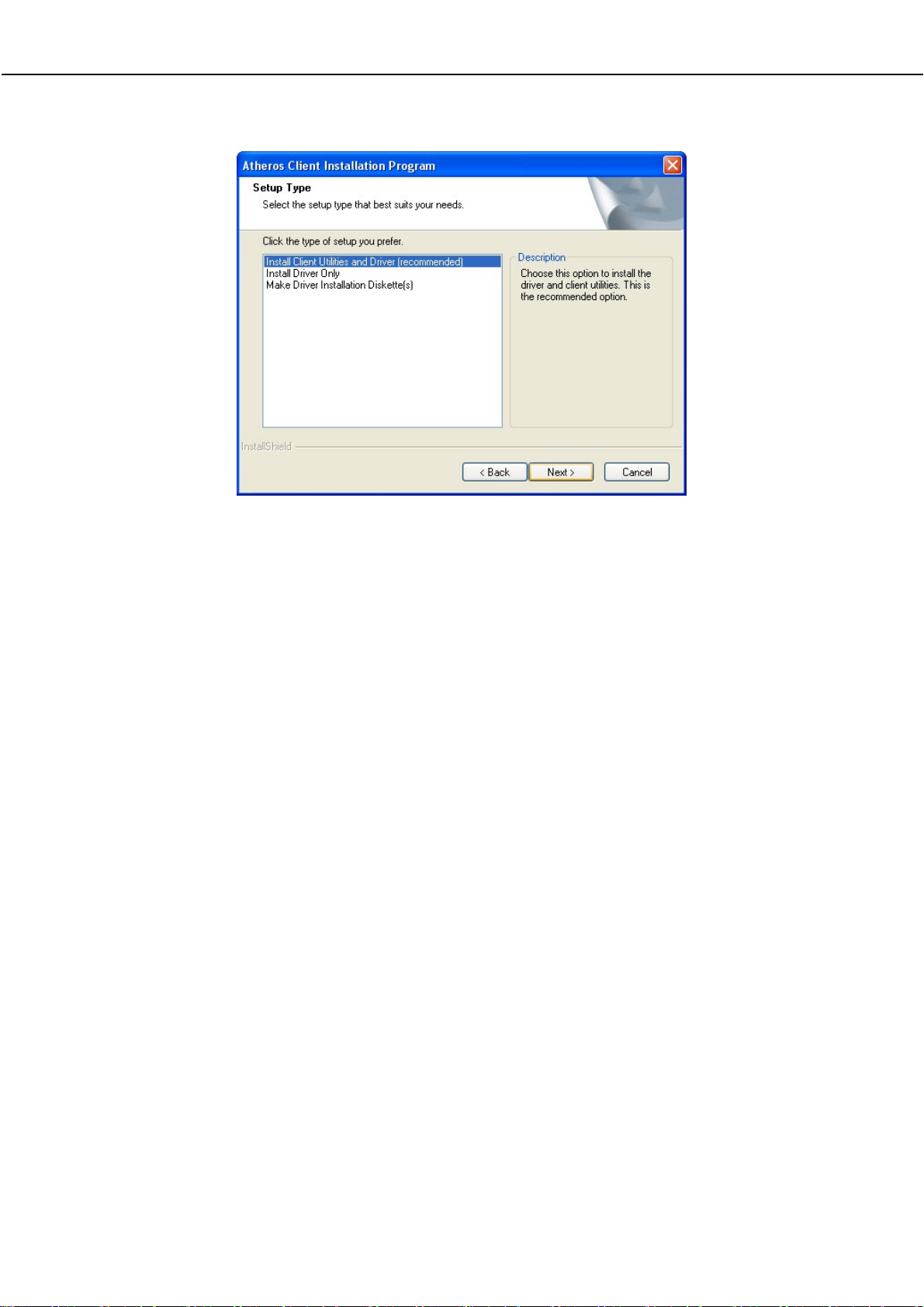
3.3 Diagnostics Tab
The Diagnostics tab lists the following receive and transmit diagnostics for
packets received by or transmitted to the network adapter.
•
•
• Unicast packets transmitted and received
• Total bytes transmitted and received
Multicast packets transmitted and received
Broadcast packets transmitted and received
Page 18
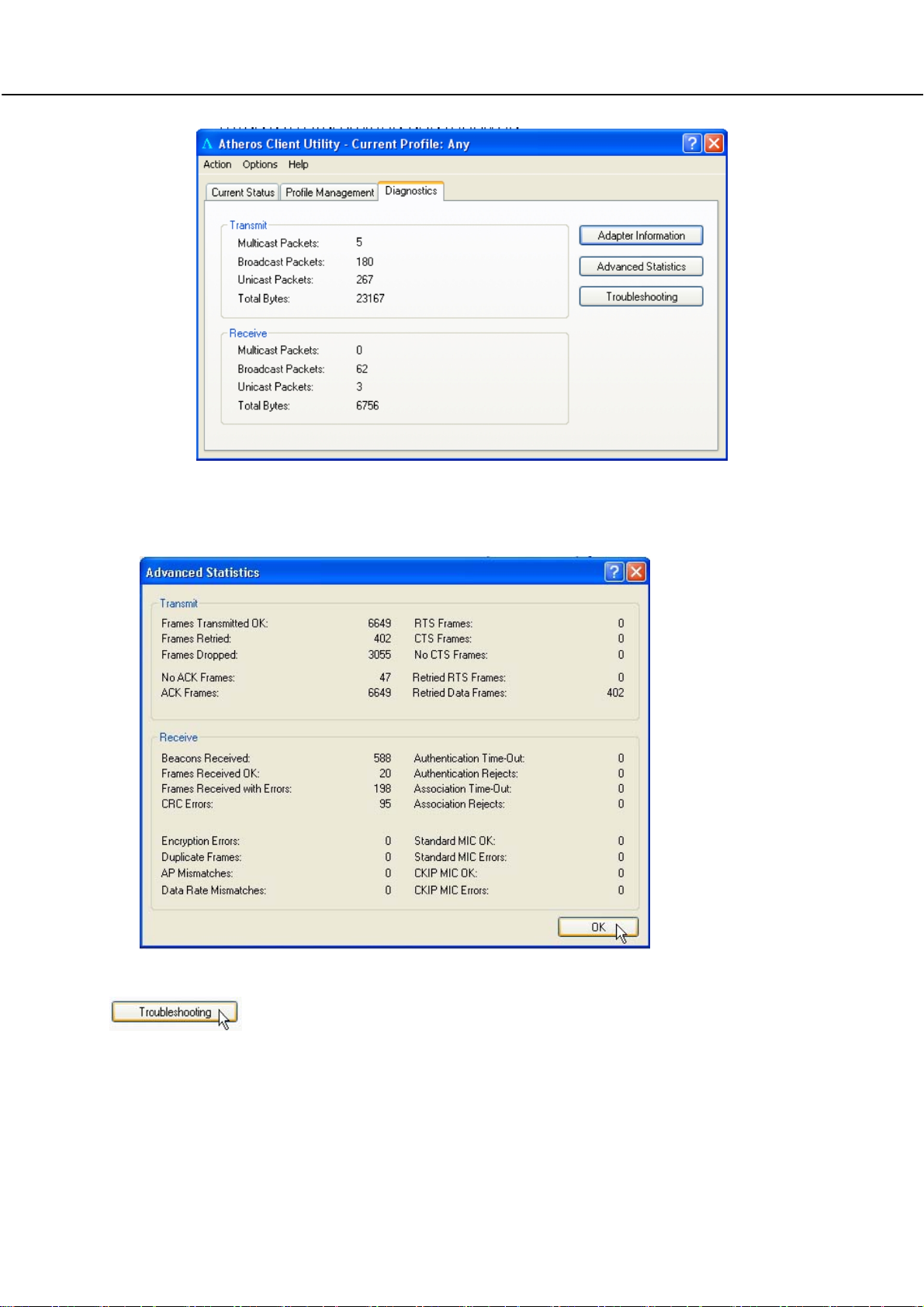
This button shows more deta iled statistical information on frames that are
either received by or transmitted by the network adapter.
This button allows you to run the diagn ostic test, save the test report and
view the test results on the wireless adapter configuration and association.
Page 19

Chapter 4 Utility Configuration
This cha pter will elaborate on the Cl ient Manager configuration of th e network
adapter using some simple examples.
the wireless clients communica te t hrough route r, which are devices that
act as base station for all wireless communication. Data packets from the
wireless clients a re tra nsferred t o the wi reless route r be fore be ing
transmitted to other h osts on the netw ork. The number of w ireless clients
supported depends on the router.
Page 20

4.1 Co nfiguration Mode
In this example, three work station act as wireless clients to communicate
with the w ireless router. Once all con figuration ha s been done, wire less
clients w ith the sam e SSI D as the AP will be abl e to acc ess wirelessl y to
PC1 via the wireless router
For Router
Ensure that yo u have en abled the DHCP server in your router an d that
your wireless clients are set to receive their IP address dynamically so that
the wireless router can assign an IP address to them. Note th e w ireless
configuration settings of your router as shown in the figure above.
Page 21

For PC 1
1. Activate your utility.
2. Go to the
Profile Management
tab, click on the
Scan
button to look
for the wireless AP.
3. Click on the
wireless AP . Once found, se lect the
the router:
wireless-router
Refresh
butto n if you r syst em is un able t o de tect yo ur
Network Name (SSID)
used by
and click on th e Activate button to add i t
to your profile list.
Notice that the SSID has already been pre-configured in this profile.
Page 22

The SSI D of both the wireless router and the wirele ss cl ient must b e t he
same for them to communicate with one another.
4. E nter the
Profile Name
, e.g. Workstation 2 for easy identification.
Page 23

5. Next, proceed to the Security tab . The wire less cl ient must us e t he
same se curity m ode as the ro uter. In our example , s elect
Passphrase
and click on the
Configure…
button.
WPA
6. Enter the enc ryption key in th e fi eld p rovided. Pl ease note that this
key must be the sa me a s the one that you had configured for your
wireless router.
7. Click on the OK button to update the changes.
Proceed t o you r
the router and the wireless client (PC2).
Current Status
tab to mon itor the connection b etween
Page 24

Alternatively, you can a lso check the con nection from the MS-DOS
Prompt. Fr om PC2 , simpl y p roceed to the
cmd
. Click on the OK button.
In the MS-DOS Prompt window, type
address belongs to your access point.
When the screen appears:
Pinging 192.168.168.1: bytes=32 time=2ms TTL=128
Pinging 192.168.168.1: bytes=32 time=2ms TTL=128
Pinging 192.168.168.1: bytes=32 time=2ms TTL=128
…….
This indicates that the con nection betw een the ac cess p oint an d the
wireless client has been established successfully!
ping 192.168.168.1 –t
Start
Menu,
Run…
and type i n
, whereby this IP
4.2 Prof ile Management
This option allows you to manage your profile(s), set your security options,
and scan for other wireless networks.
Page 25

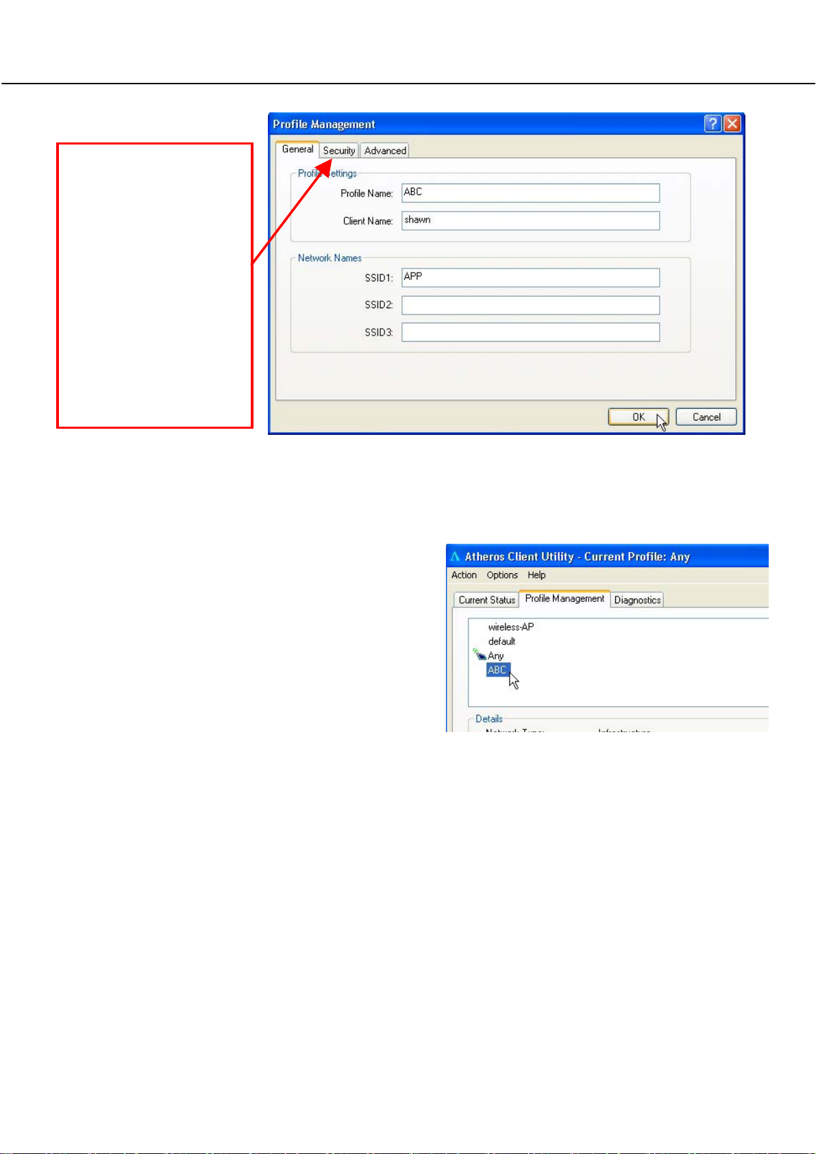
Click on New b utton to cr eate a new profil e. Enter the profile name ( a
unique name to identify th is p rofile), a cl ient n ame and the SSI D of th e
wireless netw ork to conne ct to. Note that the
name that is registered to your PC. You can enter up to 3 different SSIDs in
order of pref erence, p er profile. We are usin g ABC as th e prof ile n ame
and APP as the SSID1
Client name
refers t o th e
Page 26
r
For d etails o n h ow
to set the dif ferent
authentication and
encryption types
available u nde
the
Security
Ta b,
kindly re fer to
Chapter 7 “Types
of Authentic ation
and Encryption
mode”
Click on the OK button to update the changes.
Notice that ABC has been add ed
to the profile list.
Page 27
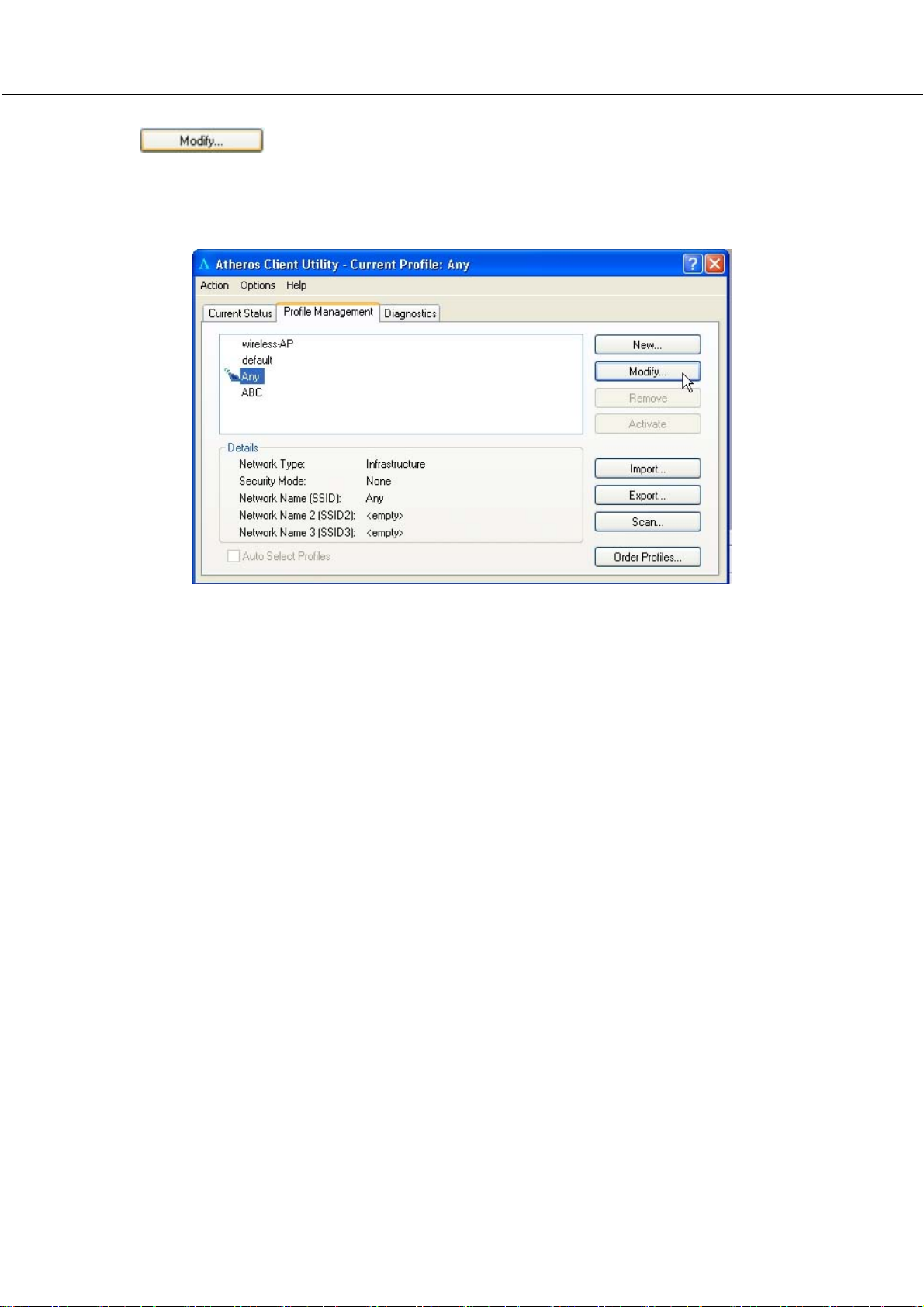
To mod ify a n e xisting profile, select the profile that you wish to m odify
and click on this button. We are using profile:
Any
as an example.
Page 28

To delete an existing profile, select the particular profile that you wish to
delete a nd cl ick on this b utton. We are usin g p rofile:
example.
Note th at th e ac tive prof ile ( the pr ofile th at you a re c urrently u sing)
cannot be deleted!
Active profile
indicated by this
icon cannot be
deleted!
default
as an
Page 29
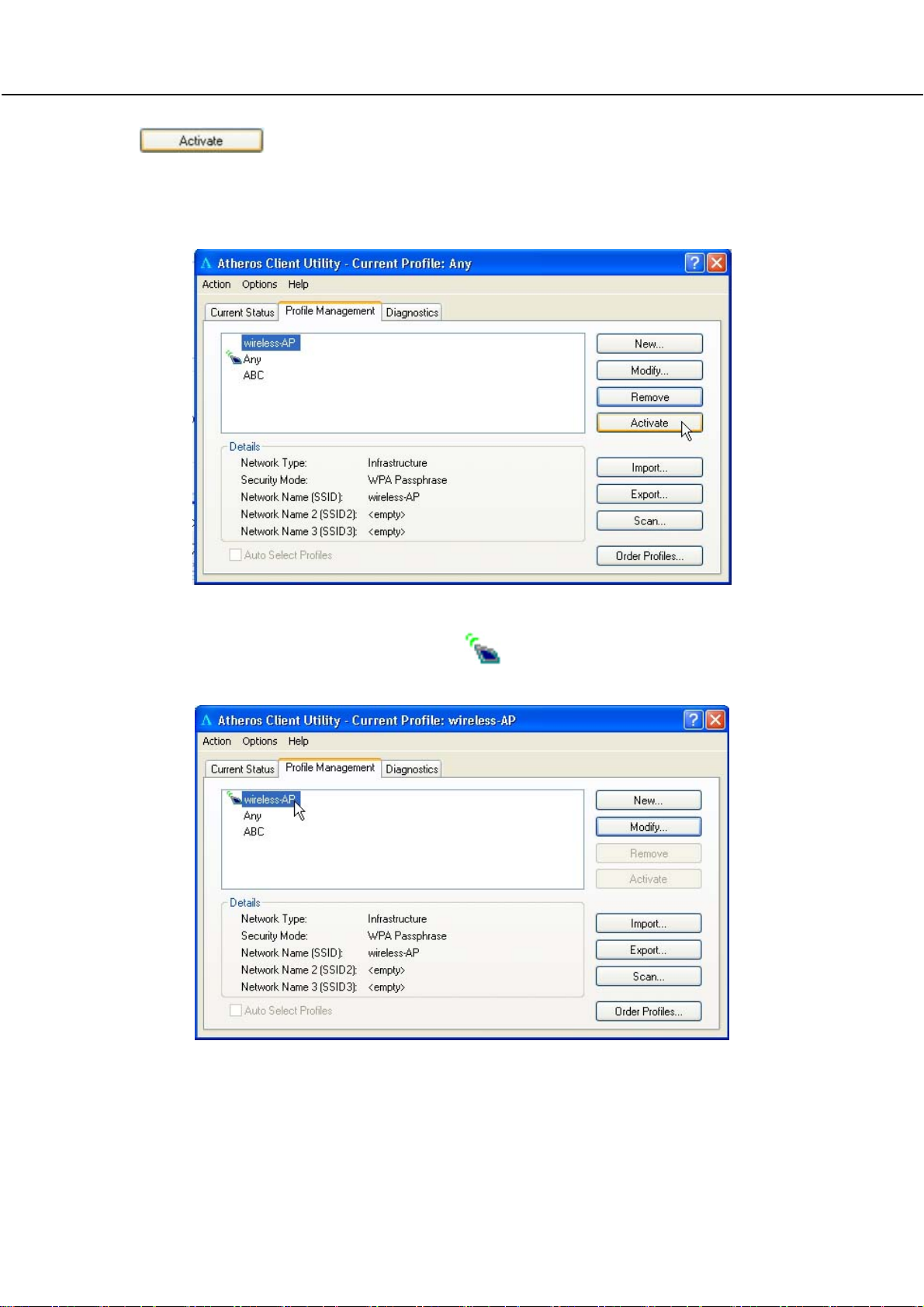
To activ ate a profile, selec t the p rofile and c lick on th is button . W e are
using profile:
wireless-AP
as an example.
Once a profile is activated, this icon w ill app ear next to t he p rofile
name: wireless-AP.
Page 30
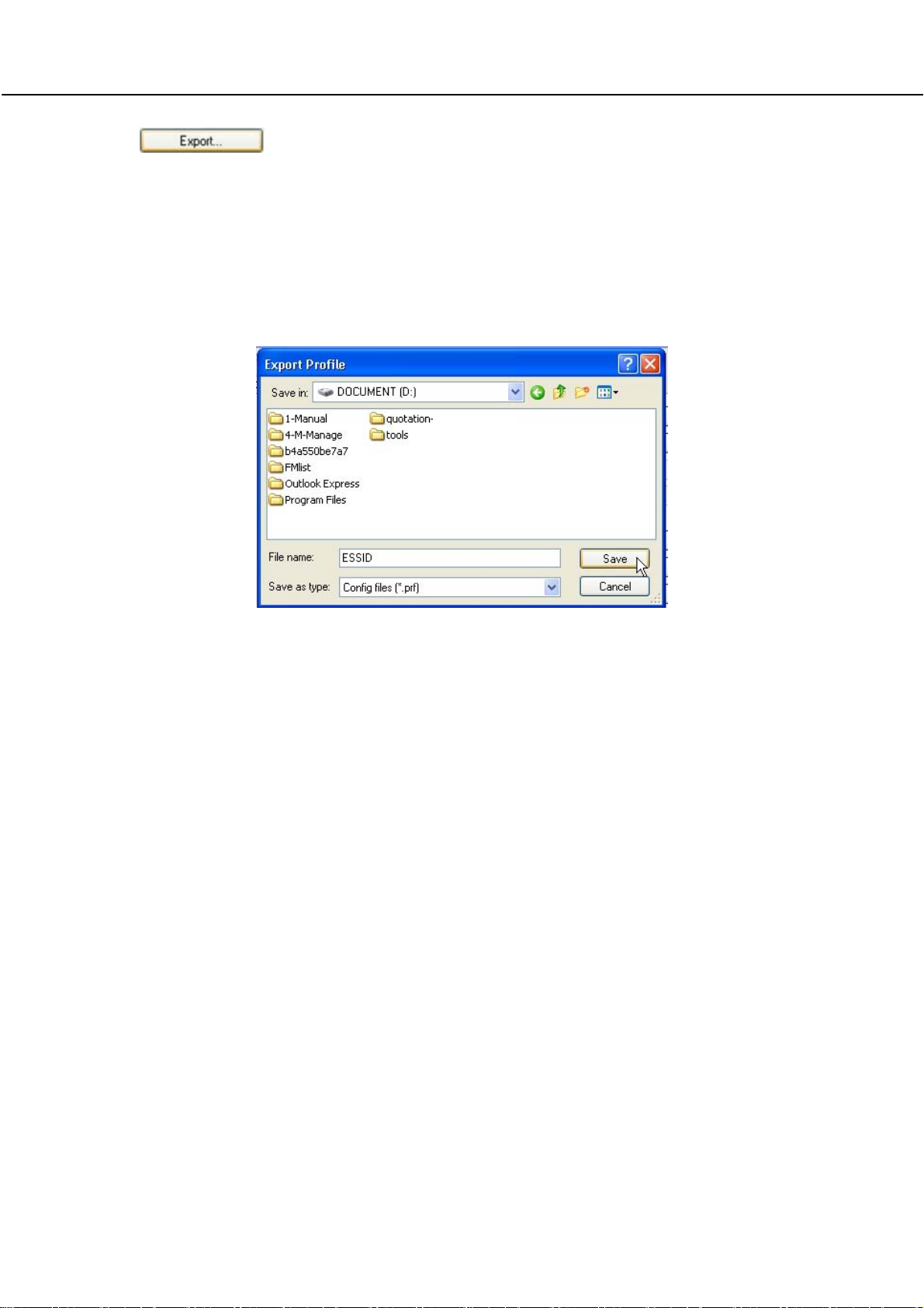
This fu nction allows y ou to save th e s ettings of y our p rofile on to disk.
Select the profile that you w ish to sa ve and click on this button. We are
using profile:
Choose th e f older to s ave to, en ter the name u nder w hich to save th e
profile and click on the
ESSID
as an example.
Save
button.
Now, your profile is saved to your selected folder.
Page 31
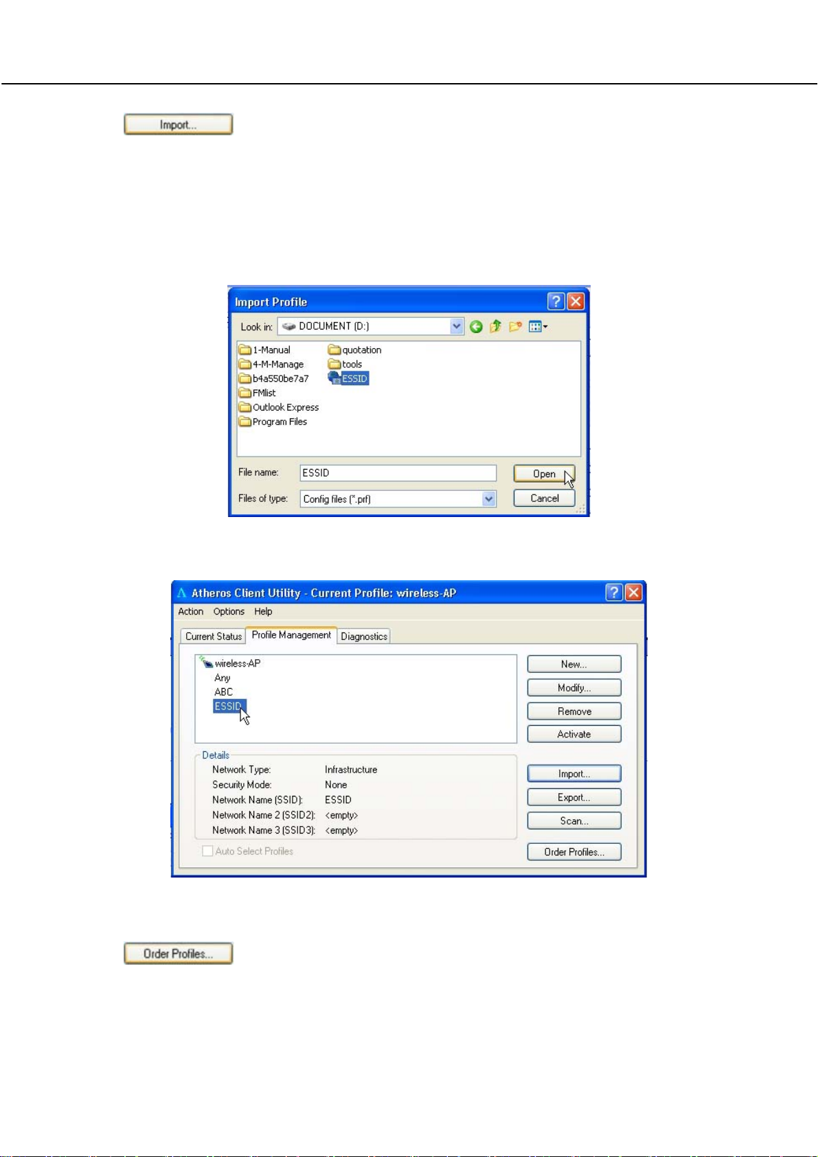
This function all ows you to retrieve a saved profile from disk. We are using
profile:
Go to the folder where you have saved your profile, select ESSID.prf and
click on the Open button.
ESSI
D as an example.
Notice that the profile: ESSID has been imported to the list of profiles.
If you ha ve crea ted se veral profil es, th is function allow s y ou to establ ish
the priority order in which the network adapter should try to connect to a
WLAN. If the netw ork adapter is unabl e to con nect to a w ireless network
Page 32

through t he 1st profile, it will then try to conn ect using the 2nd profile and
so on.
Notice that if this function is
disabled, this means tha t
you have not a dded any
profile in the
Profiles list.
Auto Selected
When auto pr ofile se lection is en abled,
the network adapter scans for available
wireless networks and will connect to the
highest p riority profile that matches the
networks detected.
To do so, simply click on t he Add button
from the Available Profiles list. Refer to
the screen shown below.
Please note tha t y ou need AT LE AST TWO p rofiles to a ctivate the Auto
Select Profiles function; and that each of your profile must connect to at
least one Network Name (SSID).
Notice that when a selected profile has been added, it will be transferred
to the
Auto Selected Profiles
list.
Page 33

Select and click on the Add button to transfer another profile.
You need to transfer at least two profiles to the
to activate the
Auto Select Profile
function.
Auto Selected Profiles
list
Transmit Power Level
Specifies the wire less tra nsmit p ower to be used. Reducin g the power
level lowers the risk of interference with other nearby wireless devices and
conserves battery power but decreases radio range.
Power Save Mode (Only applicable to Infrastructure mode)
This feature reduces power consumption by the PCI adapter. There are 3
options for this mode:
•
Off
The p ower ma nagement i s disabled and the ca rd consume s full
power from the computer.
•
Normal
The d river tu rns of f th e po wer to the adapter for br ief pe riods over
briefly spaced time intervals.
•
Maximum
The dri ver tu rns o ff po wer to the adapter fo r l onger perio ds ove r
more widely spaced time intervals.
The g uideline for choosin g be tween the
Normal
and
Maximum
options:
Page 34

The P CI ad apter wakes u p more often an d res ponds sooner to
network requests in
Maximum
mode consumes less power than
Normal
mode than in
Maximum
Normal
mode; and the
mode.
Network Type
Select ei ther Infrastructure if y ou are conn ecting to the W LAN u sing an
access point
802.11b Preamble
The preamble is part of the I EEE 80 2.11b physical layer specification. It is
mandatory f or all 802.11b devices t o support the long preamble format,
but they may op tionally s upport th e s hort pr eamble. T his P CI ad apter
supports both the short and long preambles.
•
Short & Long
This option allow s communication with o ther 802. 11b devices tha t
support short preamble to boost the throughput.
•
Long Only
If your d evice is having trouble to com municate with other 802 .11b
devices, you may try to select the Long Only option.
802.11 Authentication Mode (Only appli cable to Infrastructure mode, after you
have enabled the encryption mode)
Select w hich m ode t he w ireless a dapter uses to auth enticate to an
access point:
•
Auto
Causes the P CI a dapter to atte mpt au thentication using share d
authentication. It then sw itches to op en a uthentication if shared
authentication fails.
•
Open
Enables the PCI ad apter to attempt authentication regardless of its
WEP se ttings. It will only associa te w ith the acc ess p oint if i ts W EP
settings match those of the access point.
•
Shared
Allows the ad apter to au thenticate and associate only if it has the
same WEP settings as the access point
Page 35

Appendix
1.Technical Specifications
Network Protocol, Standards and Electrical Emissions
Industry Standards
Operating Frequency
Modulation •
Antenna Type
Network Interface
•
IEEE 802.11g
•
IEEE 802.11b
Performance
• 2412~2462MHz
Binary Phase Shift Keying (BPSK)
•
Quadrature Phase Shift Keying (QPSK)
•
Complementary Code Keying (CCK)
• 16 QAM
•
64 QAM
•
DBPSK
•
DQPSK
External 2dBi antenna and an SMA-type
connector
PCI 2.3 compatible
Physical and Environment
Environmental Requirements
Operating temperature:
Storage temperature:
Operating humidity:
Non-operating humidity:
Power Consumption 3.3V DC, 2A
Physical Dimension 60mm x 46 mm x 14 mm (LxWxD)
0°C to 50°C
-20°C to 70°C
10% to 70% RH
5% to 90% RH
 Loading...