

Page 1

Back to SX-S Page
r
Seite 1 von 22SONOSAX SX/S USER MANUAL
USER MANUAL
PROFESSIONAL PORTABLE
MIXING CONSOLE
SONOSAX SX-S/SX-V
INTRODUCTION
Your SONOSAX SX-S or SX-V mixing console has been manufactured to deliver many years of excellent performance.
The reliability of the SONOSAX SX-S and SX-V is due to a design combining the highest possible density with meticulous
hand assembly.
This professional mixer of optimum performance and reliability is the result of selection of choice electronic components
and severe quality control.
Audio equipment manufacture
ch de la Naz 38
CH-10252 Le Mont / LAUSANNE
SWITZERLAND
Tel (41-21) 651 01 01
Fax (41-21) 651 01 09
The information and instructions contained in this manual are necessary to ensure safe operation of your equipment and
to maintain it in good working condition.
NOTE:
120022.
SONOSAX reserves the right to modify these characteristics at any time without prior notice.
The specifications mentioned hereafter apply to all standard models as of serial numbers SX-S 16150, and SX-V
TABLE OF CONTENTS
PREPARATION
1.
OPERATING INSTRUCTIONS
INPUT MODULE after serial nb 16579
STANDARD INPUT MODULE
Differences from the newer Power / Mute modules
MASTER MODULE
-S EXTENSION MODULE
SX
26.08.2004file://D:\Z_Library\Webcopy\sonosax\SXS\sxsume.html
Page 2

INSTALLATION INSTRUCTIONS
for SX022270 SX-S Extension Module
Seite 2 von 22SONOSAX SX/S USER MANUAL
FOUR CHANNEL MATRIX MODULE
ADDITIONAL AUX MODULE
INPUT MONITORING MODULE(SX
BALANCED TRANSFORMER OUTPUT MODULE
SONOSAX SX
-V
TIPS ON USING YOUR MIXER
-V only)
1. PREPARATION
1.1 Opening the cover
Release the 2 slide-locks and simultaneously slide out the cover.
1.2 Closing the cover
Replace the cover and slide all the way in until the locks catch.
1.3 Removing the battery compartment
Make sure that the handle is in rest position. Remove the battery pack by releasing the 2 slide-locks, tilting the
compartment diagonally towards you and lifting it out over the handle.
IMPORTANT:
out of the mixer.
Keep the slide-locks pressed towards the center untill the battery compartment is completely lifted
1.4 Opening the battery compartment
The battery compartment may now be opened by loosening the screw on the left. Remove the plastic side cover.
Insert:
{
8 alkaline D-cells or 8 rechargeable nickel-cadmium batteries for the SX-S6
{
10 alkaline D-cells or 10 rechargeable nickel-cadmium batteries for the SX-8 or SX-S10.
On the left of the battery compartment, you will find the hex wrench (2mm) which will enable you to
NOTE:
completely disassemble the SX-S without using any other tool.
WARNING :
contains rechargeable NiCd batteries. To ensure optimal autonomy, use only professional alkaline D-cells. Also
check the manufacture date of D-cells.
Never leave discharged batteries in your SX-S. Make sure before charging that your SX-S only
26.08.2004file://D:\Z_Library\Webcopy\sonosax\SXS\sxsume.html
Page 3

Seite 3 von 22SONOSAX SX/S USER MANUAL
1.5 Closing the battery compartment
Replace the plastic side cover.
NOTE :
compartment if such batteries are used. Your nearest SONOSAX agent or the manufacturer in Switzerland can
provide assistance should a problem arise due to this difference in length.
Replace the battery compartment while holding in the slide-locks and making sure the power contacts are correctly
positioned.
The battery compartment is in place when the slide-locks return easily to their original position.
Certain D-Cells are longer than standard D-Cell batteries and slight difficulty may be found in closing the
1.6 External power supply (also refer to 2.2 and 2.3)
SONOSAX SX-S mixers can be powered from a 9-15V DC (SX-S6) or 11-15 DC (SX-S8/10) power supply capable
of delivering at least 1.5A. Average power consumption is approximately 500mA.
The DC power supply input connector (LEMO, Type FGJ IB 303CLLD62, SONOSAX Part nb. 860202) is located
on the rear panel of the SONOSAX mixer. Pin No.3 is allocated to the NiCd batteries charge current. Nominal
current is 400mA and nominal charging time is 15 hours.
WARNING :
DO NOT ATTEMPT TO CHARGE D-CELL BATTERIES.
1.7 Power supply block diagram
1.8 Fuses
Your SONOSAX SX-S is protected against overloads and reversed polarity by two T2.5A fuses located : INSIDE
THE BATTERY COMPARTMENT (ON THE RIGHT). To replace the fuse,remove the cover on the right of the
battery compartment with the hex wrench.
NOTE :
{
ON THE EXTERNAL DC PC BOARD. Located below the two faders of the master module. To gain access
to this fuse, remove the bottom of the SX-S mixer with the hex wrench.
Here you will find spare T2.5A fuses
.
RETURN TO TABLE OF CONTENTS
2. OPERATING INSTRUCTIONS
2.1 Switching on the SONOSAX mixer
Using D-cells or NiCd batteries:
Depress POWER push-button on the master module. The two control LEDs of the modulometer should light up
within 3 seconds. If they do not light up:
{
Check that batteries have been inserted correctly inside the battery compartment.
26.08.2004file://D:\Z_Library\Webcopy\sonosax\SXS\sxsume.html
Page 4

{
)
If necessary change the batteries.
Using the Sonosax external power supply:
Seite 4 von 22SONOSAX SX/S USER MANUAL
IMPORTANT :
220V depending on local current supply. If needed, change selector position by using a screwdriver, a ball point
pen or similar instrument. At 110V, the mixer may be powered from 100 to 125V , 50 to 60 Hertz; at 220V, from
200 to 260V, 50 to 60 Hertz.
Newer SX-S Mixers use an autoranging power supply. It may be powered from 100 to 250 VAC 50 to 100 Hertz.
{ The POWER button on the master module should not be pressed while using the external power supply or
while charging accumulators.
{ The GND button separates the SX-S from ground (in case of ground loop).
Before turning on the unit, make sure the voltage selector is correctly positioned at either 110V or
2.2 Using an external power supply
Apply current indicated (see 1.6) between points 1 (+) and 2 (0V) of the LEMO connector. Do not press the
"POWER" button while using an external power supply or while charging accumulators.
2.3 Battery test
When BATT TEST push-button is depressed, the LEDs of the modulometer will indicate the average charge per
cell (minimum 1V, maximum 1.5V).
2.4 Low charge alarm
When the average charge per cell reaches 1.05V, the two LEDs will automatically start to blink. This alarm means
that about 10 to 20 minutes remain before the mixer automatically turns off. This auto-stop protects the
accumulators from excessive discharge.
2.5 Charging the NiCd batteries
WITH SONOSAX SX-S POWER SUPPLY :
This external accessory will automatically charge the NiCd batteries while the mixer is being used. Simply press
the charge 0,4A button. The green "CHARGE" LED on the power supply as well as the green LED on the Master
Module should light up. Nominal charge current is 400mA and nominal charging time is 15 hours.
WITH ANOTHER EXTERNAL POWER SUPPLY :
Apply current charge of 400mA to pin 3 of the LEMO connector. Nominal charging time is 15 hours.
IMPORTANT:
Never charge D-Cell batteries!
RETURN TO TABLE OF CONTENTS
3. INPUT MODULE (after serial nb 16579
26.08.2004file://D:\Z_Library\Webcopy\sonosax\SXS\sxsume.html
Page 5
Seite 5 von 22SONOSAX SX/S USER MANUAL
Traditional professional mixing consoles are all based on the same input structure. The signal from the microphone
goes through a phase reversal switch and then to a pad to attenuate the signal before going to the first
amplification stage. Some mixers even introduce a transformer before the first stage to simplify the circuits.
Reducing the signal level before amplifying it increases any noise. It also limits the range of input signal that can
be accommodated before overload distortion. This type of circuit has been OK for analog recording.
The new SONOSAX SX-S input stages do not reduce the microphone level before amplification. Instead we
control the amount of amplification. No new noise is introduced by this method.
By careful design of the input amplifier stages, it is now possible to handle a significant increase in the input level
before overload. Conventional input stages require the operator to do a delicate balancing act between the input
gain control and the channel fader to prevent unexpected input overload or so much gain that the noise comes up.
Thus, heretofore unattainable low noise input figures and high input headroom figures are a reality.
The new SONOSAX SX-S input modules have a new profile. The "Limiter Threshold", "AUX Level" and "PAN"
controls have been recessed. This removes any obstacles beside the P&G faders. Functionally the input modules
are the same as they have been for over a decade. The electronic components and the circuitry are modern. The
functionality was perfected many years ago. The SONOSAX SX-S still has the best limiter in the industry and
equalization control equaled by none.
The new SONOSAX SX-S input module has mini-switches on the back to change several parameters of its
operation. The "High Pass" filter can be switched in or out of the signal path with the "Equalization" or it can be in
the circuit all the time. The ON/OFF switch can actually turn the power to the channel OFF to preserve the
batteries, or it can be a "Mute" switch which can activate the channel without a pop in the signal. The switch to
select "Phantom 12V" or "T12V " power is of course still there.
The new modules are prefitted with connectors for VCA operation and the installation of the four Channel Matrix
Module and the AUX Module.
3.1 SONOSAX SX-S Input Module Specifications:
GAIN
Nom. input level 87 uV 1.55 mV 15.5 mV 155 mV 1.55 V
Max. Input level 2.57 mV 12 mV 120 mV 1.2 V 7.0 V
THD & N% 0.028 0.016 0.01 0.007 0.007
CMRR at 1kHz -103 dB -103 dB -104 dB -95 dB -78 dB
CMRR 20 Hz to
20
85 dB
Fader at +10 dB
-85 dB -85 dB -85 dB -80 dB -60 dB
Fader at 0 dB
60 dB
Fader at 0 dB
Fader at 0 dB
40 dB
20 dB
Fader at -4 dB
0 dB
Equivalent input Noise Ohm Source
GAIN
Noise linear -129.3 dB -128.4 dB -125.6 dB -110.5 dB -91.4 dB
Noise ASA A -131.6 dB -130.6 dB
85 dB
Fader at +10 dB
Bus Noise
6 Channels assigned @ Gain Fader at -4 dB -86 dBu
1 Channels assigned @ Gain Fader at -4 dB
Fader at 0 dB
60 dB
40 dB
Fader at 0 dB
-127.4 dB
20 dB
Fader a t0 dB
-111.9 dB
-91.4 dBu
Fader at -4 dB
0 dB
-92.5 dB
26.08.2004file://D:\Z_Library\Webcopy\sonosax\SXS\sxsume.html
Page 6

Seite 6 von 22SONOSAX SX/S USER MANUAL
6 Channels assigned Faders Down -89.5 dBu
Master Faders @ OdB, all channels off -94.2 dBu
Master Faders Down -95.5 dBu
3.2 Installation Procedure
Disconnect the Neutrik and dual Bantam connector from the module circuit board and install them in the
appropriate blank holes on the mixer's back panel.
First install the Neutrik connector with the lock towards the top of the SX-S, then install the Bantam plug with the
cables oriented towards the top of the mixer.
Install the module into the appropriate slot, reattach the three connectors and connect the module to the ribbon
connector.
If the mixer is fitted with an Aux module and / or Matrix module connect J-5 tothese modules.
Before reattaching the cover, select mute or power mode with S-4, Lo frequency cut with EQ-switch or continuous
with S-5 and "Phantom " or " T12V " with Switch S-8.
3.3 Phase reversal
Reverses signal phase without reversing mic powering.
3.4 HI / CAL / LO Switch position
The Cal position is calibrated for unity gain if faders are at zero. For example a Line Input of + 6 dBu will output +
6dBu. The Gain control has no effect in this position. The HI position gives 20 to 75 dB range of the Gain control
Faders at unity gain.
3.5 LO position
The LO position gives 7 to 42 dB range of the Gain control Faders at unity gain.
3.6 Equalizer
The SONOSAX SX-S equalizer is equipped with the following filters:
{
L.F. CUT: low frequency filter at fixed slope 12 dB per octave. The cutting frequency is progressively
adjustable from 20 Hz to 500 Hz.
cut or not depending on the position of S-6 on the circuit board
{
80 Hz and 8 kHz: bass and treble adjustement
{
M.F : medium frequency adjustement, from 200 Hz to 8 kHz.
{
The EQ switch allows the filtering of 80 Hz, 8 kHz and MF tones.
3.7 Pan Pot (Panoramic Potentiometer)
The Pan Pot allows progressive switching of the modulation from left to right.
The EQ in switch can be configured to include the LO frequency
NOTE:
26.08.2004file://D:\Z_Library\Webcopy\sonosax\SXS\sxsume.html
Page 7

Seite 7 von 22SONOSAX SX/S USER MANUAL
3.8 ON Switch
With S-4 on the circuit board in Power position this switch turns the entire power to the module on and off. An
audible pop will be introduced on the mixer's output if this switch is used during operation. This function is useful to
conserve power when only a few channels are being used.
With S-4 on the circuit board in Mute position all power is applied to the module but its output is muted unless the
switch is depressed. Channels can be preset and switched on to the mix bus during operation with no pop.
3.9 Aux level
The AUX potentiometer (auxiliary) allows separate mixing of different inputs for mono output or special effects
such as an echo room, etc. The PRE/POST push button allows selection of the modulation before (PRE) or after
(POST) the fader.
3.10 Limiter
Each input module is equipped with a limiter. The audio level above which the limiter is activated (Limiter LED lit) is
controlled by the THRESHOLD knob. The limiter may be automatically activated if the input gain is too high. This
will avoid saturation and ensure a supplementary margin of 6 dB over the maximum input level. This is why the
limiter cannot be switched off.
The limiter has no effect whatsoever provided the Limiter LED does not light up.
NOTE:
3.11 Overload LED
The OVD LED lights up 4 dB before saturation level. Overload is measured at mic amplifier output and the
equalizer output levels.
3.12 Pre - Fader Listening
The PFL selector allows pre-fader listening of each input after equalization.
3.13 Input Connector
The SONOSAX SX-S is equipped with NEUTRIK input connectors equivalent to XLR, Canon, Switchcraft, etc. The
standard SX-S version is equipped with female connectors.
The input is floating balanced, transformerless, to ensure optimal performance. On request, the SONOSAX SX-S
inputs may be equipped with high frequency R.F. filters.
Bridge PIN 3 to PIN 1 for asymetrical use!
NOTE:
DO NOT USE MIC POWER!
3.14 Insert Connectors
These are 3-pole, 4.4mm Mini-Jacks. The corresponding connector with 2 meters of cable, other end free is:
SONOSAX Part Nr 860133. Plugging the jack in INSERT opens the circuit between the LF cut output and the
equalizer, for insertion of a filter special effect, with asymetric send-return. This jack may also be used as a line
input. In this case, use only the return contact of the jack. The line input at this point avoids passing through the
26.08.2004file://D:\Z_Library\Webcopy\sonosax\SXS\sxsume.html
Page 8

input pre-amplifier.
Seite 8 von 22SONOSAX SX/S USER MANUAL
3.15 Line out connectors
Same Mini-Jacks as INSERT connectors. Independent asymetrical output. One of the contacts gives the
modulation before fader (PRE) and the other after the fader (POST).
3.16 Input module configuration
RETURN TO TABLE OF CONTENTS
4. STANDARD INPUT MODULE
Differences from the newer Power / Mute modules
4.1 Power on/off push-button (red knob)
Each input module is equipped with an ON/OFF switch (red knob) in order to optimize power consumption, if all
inputs are not used.
WARNING:
Optional MUTE push button (gray knob), replaces Power on/off: supplies constant module powering. The gray
knob turns modulation on and off silently ( no pops).
Do not switch on an input module during a sound recording as this causes a pop.
4.2 30 dB PAD (Input attenuator)
To be switched on when the OVD LED lights up at minimum gain control setting. This happens, for instance, when
high level input sources such as a tape recorder or a condenser microphone at high acoustic levels are used.
4.3 GAIN
26.08.2004file://D:\Z_Library\Webcopy\sonosax\SXS\sxsume.html
Page 9

Seite 9 von 22SONOSAX SX/S USER MANUAL
This potentiometer allows adjustment of the global gain from 24dB to 85dB, and with PAD on from -6dB to 30dB.
The gain control should be used with great care since the adjustment range is extensive.
4.4 L.F. CUT
Low frequency filter at fixed slope 12dB per octave. The cutting frequency is progressively adjustable from 20Hz to
500Hz.
This filter is not disconnected by switching off the EQ push-button.
NOTE :
RETURN TO TABLE OF CONTENTS
5. MASTER MODULE
5.1 Master faders
There are two separate faders to permit different adjustments between right and left. Calibration position (0dB) is
at the end of the fader stroke length.
5.2 Monitor level & mono test
The control section of the SONOSAX SX-S includes the modulometer, the output listening (phones) and the output
monitor. As long as no PFL button has been switched on, the modulometer and the output listening are controlled
by the main L+R output signal. As soon as a PFL button is depressed, the modulometer and the output listening
automatically switch over to the input selected.
It is normal to hear a clicking sound as the buttons are depressed. Under no circumstance does this sound
NOTE:
go through the main output or any of the modulation outputs.
The MONO push-button switches the modulometer and monitor output listening to Mono in order to easily detect a
phase error. This button does not in any way affect the main output. The MONITOR output gives the same
modulation as the monitor output listening at +6 dBu,to feed, for instance, a power amplifier.
5.3 AUX master
The AUX potentiometer regulates the general mixing level of the inputs (3.9). This output is connected with a MiniJack. Nominal level is +6dBu, ground compensated.
26.08.2004file://D:\Z_Library\Webcopy\sonosax\SXS\sxsume.html
Page 10
Seite 10 von 22SONOSAX SX/S USER MANUAL
The PFL selector of the AUX section allows modulation control before the AUX Master potentiometer.
5.4 EXT or Tape return
This stereo input is connected directly to the main outputs, before the MASTER Faders. This input is intended for
Tape Return or for interconnecting 2 SONOSAX SX-S. It connects with a Mini-Jack, and is adjusted by the TAPE
potentiometer. The PFL selector of the Tape section controls stereo modulation before the potentiometer.
5.5 Oscillator
Your SONOSAX SX-S includes an internal oscillator. The oscillator may be switched on as follows:
{
THROUGH THE OSC SWITCH: In this case, the oscillator signal goes into the right and left outputs, before
the Master Faders. With the faders at 0dB, the signal is at 0dB on the modulometer scale. It is possible to
regulate the faders for a -20dB level to check the azimuth of a tape recorder.
{
BY PLUGGING A MINI-JACK INTO THE OSC 0dB PLUG: In this case, the OSC switch must not be
switched on. With a cable fitted with a Mini-Jack and an XLR male plug, you may completely check your
SX-S by re-injecting the oscillator signal into the inputs.
RETURN TO TABLE OF CONTENTS
6. SX-S EXTENSION MODULE
view of the BLOC DIAGRAM (pdf file)
The SX-S Extension module is designed to interconnect with SONOSAX SX-S mixers Serial Number 16220 and
up. Circuit differences make it impossible or impractical to install this module in earlier mixers.
Introduction
The SX-S Extension module is especially designed for the film and broadcasting industries' needs and for any
other situation where extensive intercommunication and/or monitoring features are required.
26.08.2004file://D:\Z_Library\Webcopy\sonosax\SXS\sxsume.html
Page 11

Seite 11 von 22SONOSAX SX/S USER MANUAL
6.1 The Extension module includes:
{
Communication with Boom operator over a "private line" with sidetone
{
Mono feed with the ability to talk to the agency folk
{
Special feed for video assist
{
Additional line output for a back up recorder
{
Subaudable tone on slate
{
Internal or external slate mic
{ MS decoding for the mixer's and boom operator's monitor
{ Remote roll for Stelladat and Nagra
{
Switchable VU or PPM for both channels
{
Phase correlation meter
{
Nagra 4.2. and IV-S audio in and out connectors
{
The extension module connects via a cable to the extension box that carries a wide variety of input and
output connectors.
6.2 Extension box
The extension box carries the following inputs and outputs:
{
1 Left & 1 Right balanced output on standard XLR
{
1 Left & 1 Right balanced input on standard XLR
{
Mono balanced output on standard XLR
{
Guest Line balanced output (mono-mix including talk - to guestline feature) on standard XLR
{
Left and Right Video assist output on unbalanced RCA/Cinch connectors
{
1 - 7-pin Tuchel connector to interface directly to the NAGRA IV-S Stereo inputs
{ 1 - 7-pin Tuchel connector to interface directly to the NAGRA IV-S Stereo outputs as well as Stop/Roll
functions
{
1 - 7-pin Tuchel connector to interface directly to the NAGRA 4.2. Mono inputs and outputs as well as
Stop/Roll functions
{
1 - 9 pin sub-d connector to interface directly to the Stelladat's inputs and outputs as well as Roll/Stop
functions (Stelladat must be set for single button record)
A Selector switch on the Extension box lets you choose which recorder you are going to work with. Of course, you
can always back up your work on a second recorder.
A mini-switch lets you choose between Stop and Pause operation of the Stelladat.
26.08.2004file://D:\Z_Library\Webcopy\sonosax\SXS\sxsume.html
Page 12

Seite 12 von 22SONOSAX SX/S USER MANUAL
6.3 The Boom Box
The Boom Box connects to the SX-S extension module via a 2-pair cable with 6-pin Neutrik connectors. On the
Boom Box is a boom-operator's headphone Jack (6,3mm, stereo), a standard XLR female plug to connect to a
talkback mic, or to the Boom mic if used with Y-splitters on the SX-S end. A button provides the boom operator
with the ability to call the mixer operator. A LED indicates to the boom operator that the tape is rolling.
6.4 Metering
The two high quality meter movements show the program level's Left and Right channels. The upper meter shows
the Left channel and the lower shows the Right channel. The VU-peakmeter switch selects whether the meter
movements are in VU-meter or in peakmeter mode. The mono-stereo switch selects between mono and stereo
operation. In mono mode the upper or left meter functions as a phase correlation meter, while the lower or right
meter always indicates the greater of the two signals L or R. LEDs indicate which channel is greater. The meters
can be backlit. A three position switch selects Low, High and Off.
6.5 Mixer Operator's Monitor
The mixer operator's monitoring headphone amplifier is on the left hand side of the module. A selector switch
chooses between the different sound sources: Off, Left, Right, Mono, Stereo and Auxiliary. A switch selects
between normal or MS-decoded monitoring. In MS-mode the M-(left) channel is applied to both L & R channels in
phase and the S-(right) channel is applied in phase to the left channel and out of phase to the right channel. The
ratio M to S is fixed (this decoder is only for monitoring and does not affect the main mix).
The phones potentiometer controls the headphone level for the mixer operator. The Mic potentiometer controls the
level of the operator's slate microphone. The SX-S has a built-in slate microphone that is located next to the
Stop/Roll switch on the module. An external slate microphone can be connected to the extension module. Many
operators prefer to use a slate microphone on their Headsets, which guarantees them more freedom while
working. If you have been using the internal slate microphone and want to use an external slate microphone, you
should ask your dealer for the external slate mic input. An internal jumper, JP-1 (on the operator ext. Module PCB),
lets you select 48 volt phantom power operation on the slate microphone. Sidetone is available on the monitor and
is adjustable by means of an internal trimmer (P-3). Sidetone is either pre mic level or post mic level. (Jumper-4 :
pos. 1-2 pre, pos. 2-3 post).
6.6 Boom Operator's Monitor
The boom operator's monitoring headphone amplifier is on the right hand side of the module. A selector switch
chooses between the different sound sources: Off, Left, Right, Mono, Stereo and Auxiliary. A switch selects
between normal or MS-decoded monitoring. In MS-mode the M-(left) channel is applied to both L & R channels in
phase and the S-(right) channel is applied in phase to the left chanel and out of phase to the right channel. The
ratio M to S is fixed (this decoder is only for monitoring and does not affect the main mix).
The phones potentiometer controls the headphone level for the boom operator. The Ret potentiometer controls the
(Return) level of the boom operator's talkback microphone. The boom operator's talkback microphone connects to
the boom box or, with the necessary Y-cables on the SX-S side, to a microphone transmitter or any other cable.
An internal jumper, JP-1 (on the Boom ext module PCB), lets you select 48 volt phantom power operation for the
boom operator's tbk mic. Sidetone is available on the monitor and is adjustable by the means of an internal
trimmer (P-3). Sidetone is either pre mic level or post mic level. (Jumper-4 : pos. 1-2 pre, pos. 2-3 post).
6.7 Communication
The SX-S Extension Module has comprehensive communication features. The mixer operator can talk to three
different destinations and can receive calls from the boom operator.
26.08.2004file://D:\Z_Library\Webcopy\sonosax\SXS\sxsume.html
Page 13

Seite 13 von 22SONOSAX SX/S USER MANUAL
6.8 Slate button
The slate button routes the slate microphone to the main L & R outputs, and if jumper 9 is installed, also to the
AUX mix-bus (jumper 9-slate to AUX). By selecting pos. 4 on the DIP mini-switch a 27 Hz slate tone is sent to the
main mix, and AUX (if jumper 9 is installed), every time you press the slate button.
6.9 Guest button
When pressing the Guest button the slate microphone is routed to the guest monomix. This allows the mixer
operator to talk to the agency folk independently and lets her or him keep the so called "private line " with the
boom operator.
6.10 Boom button
The boom button routes the slate microphone to the boom operator's headphone monitor and it also routes the
boom operator's tbk microphone to the mixer operator's headphone monitor if "Boom active" is off. If boom active
is on, (DIP mini-switch S-1 pos. 2 on), the boom operators tbk mic is permanently routed to the mixer operator's
headphone monitor.
6.11 Boom LED
This LED lights as soon as the boom operator pushes his call button on the boom box, (provided that pin-6 of the 6
pin Neutrik and Gnd are connected to the Boom Box and the SX-S). This feature is used for the boom operator to
call the mixer operator without disturbing the mixer operator in his work. There are 2 modes configurable by the
DIP-mini switch:
{
Memory: The call LED will light and stay lit until the mixer operator pushes the boom operator button on the
extension module which resets the LED. This operation implies that the mixer operator and boom operator
can talk to each other while the mixer operator is pushing the boom button. After the operation is
completed the LED will be off until the boom operator calls again.
{ Call LED momentary: (DIP mini-switch S-1 pos. 3 on), In this mode the call LED lights only momentarily
while the boom operator is pressing the call button.
6.12 STOP/ROLL
The STOP/ROLL controls the recorder connected to the SX-S. In Stop the recorder is in Stop mode and in Roll the
recorder is in Record mode and is recording audio material through the SX-S Mixer. One exception is the
Stelladat; the mini-switch on the extension box selects Stop or Pause. That is: Stop on the extension module can
either be Stop or Pause on the Stelladat, Roll is in both cases Record mode. A minor modification in the extension
box will remove the stop or pause mode; this allows a Stelladat user to go into record and record a new Start ID by
each press of the roll button. However, in this way, to stop the recorder, the mixer operator needs to push stop on
the recorder itself. (The Stelladat needs to be in one button record mode).
6.13 Roll Indication on the Boom Operator Box
An LED indicates a roll situation to the boom operator, thus the boom operator knows when the mixer operator is
recording, provided that pin-6 of the 6-pin Neutrik and Gnd are connected to the Boom Box and the SX-S.
6.14 TAPE/DIRECT Switch
26.08.2004file://D:\Z_Library\Webcopy\sonosax\SXS\sxsume.html
Page 14

Seite 14 von 22SONOSAX SX/S USER MANUAL
The Tape / direct switch selects between monitoring the Audio signal before the tape or after the tape (off-tapemonitoring). This allows you to immediately check the recorded program material, provided your recorder has the
tape monitoring feature. A Dip switch provides you with the choice of a manual or an automatic Tape/direct
function. In manual mode you use the tape direct switch to listen either before or after the tape. In automatic mode
as soon as you press the roll button you monitor the signal from tape and as you press stop the direct signal. (DIP
mini-switch 1 off auto/ on manual).
The Tape return rotary switch on the extension box selects the tape return source.
Configurations:
DIP Switch S-1
Position
1 Manual / Tape direct Automatic Off
2
3 Call LED momentary Lamp on Off
4
Function
Boom active
27 Hz Slate tone
Factory Setting
Switched
Off
Switch
Off
Off
Wiring of the 6 Neutrik connector (Boom Box connection)
Pin nb
6 2 Cable call (GND) CALL
5 2 Brown Hi Mic Boom
4 2 White Low Mic Boom
3 1 GND GND
2 1 Red Right channel H.phones
1 1 White Left Channel H.phones
Cable nb
Cable
Function
Jumper positions:
{
JP-1 48 Volts ON-OFF (Factory setting off)
{
JP-4 Pre or post mic level Sidetone pos. 1-2=pre / pos. 2-3 post (Factory setting post)
{ JP-9 Slate to AUX bus (Factory setting on)
The SX-S Extension Module is available in various configurations. It will occupy two spaces in the mixer.
6.15 SX022241 SX-S Stereo analog level & Phase meter
This module consists of two very high quality meter movements for the Left and Right channels. The meter scales
can be illuminated with two intensities. The meters can be switched to indicate as VU meters or as peak-meters.
They can also be switched between mono and stereo. In mono mode the left meter functions as a phase
correlation meter while the right channel meter always indicates the greater of the two signals. LEDs indicate
which channel is the greater.
6.16 SX022270 SX-S Extension module
This module contains the SX022241 Stereo Analog Level & Phase Meter, plus the monitoring and communication
functions, (including MS decoding). It is shipped with the necessary Neutrik 6-pin chassis connector (SX860180)
for connection to the SX-S Boom Box (SX022260) and the 12-pin chassis connector (SX860208) for connection to
the SX-S Extension Box. (SX022251). It also includes the necessary mounting hardware and connectors for
26.08.2004file://D:\Z_Library\Webcopy\sonosax\SXS\sxsume.html
Page 15

installation in an existing SX-S mixer.
Seite 15 von 22SONOSAX SX/S USER MANUAL
6.17 SX022251 SX-S Extension box
The Extension Box is a signal distribution box (300mm x 56mm x 40mm) shipped with 1,5m of cable with the
necessary connectors. Various connectors are installed in the distribution box to interface the SX-S mixer with the
Extension Module directly with the Stelladat, Nagra 4.2, and Nagra IVS, or other equipment.
6.18 SX022260 SX-S Boom box
This small box connects to the SX-S Extension Module with an optional cable (SX922120). The box incorporates a
1/4" headphone socket, a 3 pin XLR socket for a talkback microphone and a switch to call the mixer's operator with
a "Roll" indicator.
6.19 SX922120 SX-S Boom box cable
2-pair shielded cable 10 meters in length (longer on request) with 6 pin XLR connectors on each end to connect
the Boom Box with the SX-S Extension Module.
RETURN TO TABLE OF CONTENTS
7. INSTALLATION INSTRUCTIONS
for SX022270 SX-S Extension Module
7.1 Equipment:
{
022270 SX-S Extension Module
{ SX922130 Internal cable extension module - Extension Box
{ SX922140 Internal cable extension module - Boom Box
{
SX860141 Socket 1/4'' with 150mm shielded cable and Dubox case
{
SX8600342 6 Pin socket connector
{
SX860500 6 Pin socket connector with 300mm flat cable
{
SX942291 Blank Panel Jack 4.4 (2x)
{
SX980124 Allen head screw M2,5x8 (4x)
{
SX980123 Allen head screw M2,5x6 (4x)
{
SX986420 Washer ribbed M2,5 (8x)
26.08.2004file://D:\Z_Library\Webcopy\sonosax\SXS\sxsume.html
Page 16

{
SX981134 Conical head screw M3x8 (4x)
{
SX642403 24 kOhms 1% R0805 Resistor (2x)
{
SXS351220 22pF 1% C0805 (1x)
{
SXS644990 49,9 Ohms 1% R0805 Resistor (1x)
{
SXS641503 15 kOhms 1% R0805 Resistor (1x)
{
SX860131 Bantam mini-jack pre-wired (1x)
Seite 16 von 22SONOSAX SX/S USER MANUAL
{ SX140002 NPN-Transistor BC 550 C
When installing an SX022270 SX-S Extension Module in an SX-S mixing console with serial-number 16585 or
lower R-64 and R-65 on the extension module operator board need to be replaced by 24kOhms 1% SMD R0805.
7.2 Procedure
On the Master Board (solder side) solder the 6 conductors of the ribbon cable(see PCB Layout)
Change Q1 (BC337) on the Masterboard with BC 550C (SX140002).
Mount the 12-pin Hirose socket in place of the last Input's 3-pin Neutrik.
Install the 6-pin Neutrik socket next to the 12-pin Hirose socket.
Install the Extension module beside the master board and connect the wires asindicated on the PCB Layout. Do
not forget to install the additional 26-pin connector on the SX-S10 ribbon cable.
SX-S 10: Disconnect the Aux. XLR 3-pin male and replace it with SX860141,socket 1/4'' with 150mm shielded
cable and Dubox case.
SX-S 6 SX-S 8: Remove the existing 1/4'' Jack, unsolder the connections on the Masterboard and reconnect to the
Bantam Jack with cable provided. Install the SX860141, socket 1/4'' with 150mm shielded cable and Dubox case.
Click here for Illustration of INTERNAL connections, ajustments and switches
Click here for Master Module PCB Layout
The ribbon cable connects to the PCB (from Left to right) Yellow - Brown - Orange - Green - Red - Blue.
NOTE:
Connections of the 6 pole Flatcable
Brown Cable
1 PFL-BUS-left Connected to pin No 1 OP-7
Red Cable 2 MASTER-BUS-right Connected to pin No 1 OP-3
Orange Cable 3 PFL-BUS-right Connected to pin No 7 OP-7
Yellow Cable 4 Auxiliary BUS Connected to cursor Aux potentiometer
Green Cable 5 PFL Control-CDE (sense)
Connected to point R-6/R-5/collector of
Q1
Blue Cable 6 MASTER-BUS-left Connected to pin No 7 OP-3
7.3 Optional
External Slate MIC for the Mixer's operator
26.08.2004file://D:\Z_Library\Webcopy\sonosax\SXS\sxsume.html
Page 17

Seite 17 von 22SONOSAX SX/S USER MANUAL
To make the external slate Mic operational you will need to solder in R-7=15kOhms (R-5=49.9) and C-11=22pF
remove R-10 on the extension module operator board. Unsolder the internal mic on Connectors J-10 & J-11.
Then connect J-12 to the Bantam jack. Make sure that Jumper 2 is in position 2,3.
The internal Slate Mic is deactivated by this procedure.
NOTE:
SX-S10 only: Remove the unused wire on the Bantam connector.
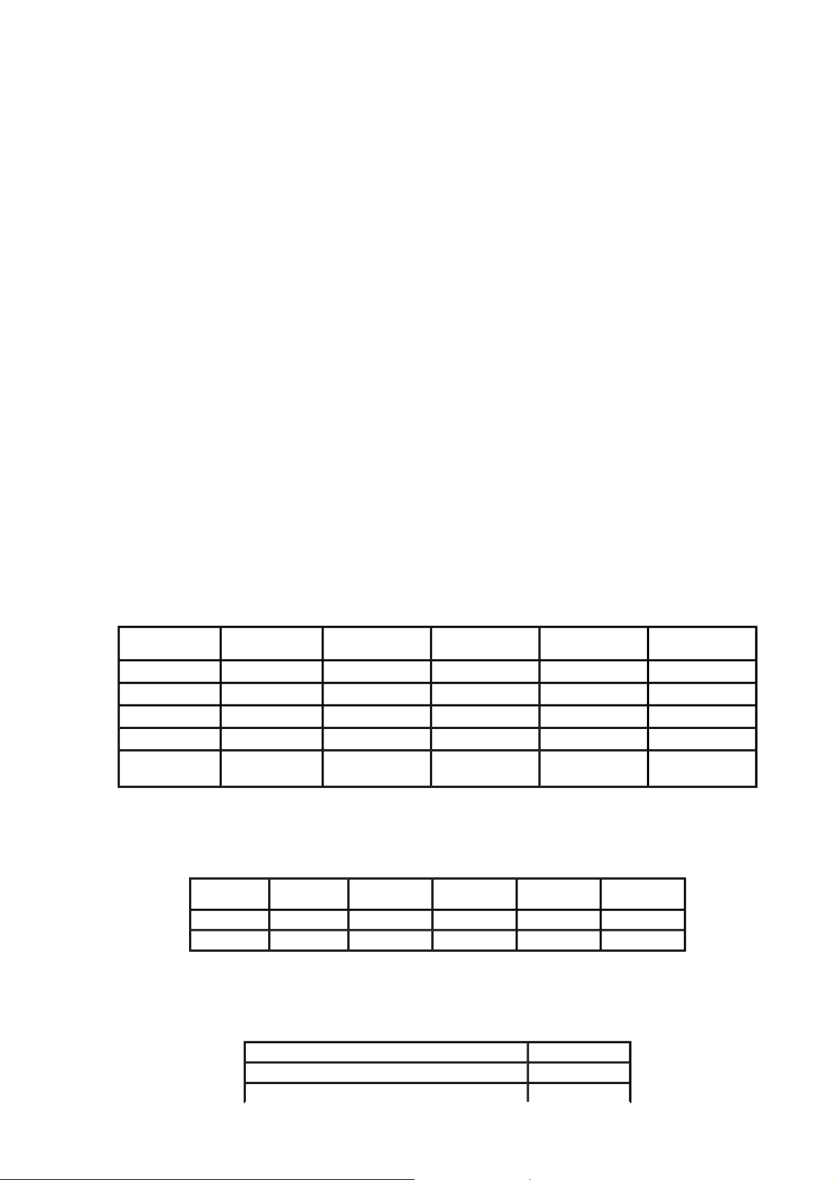
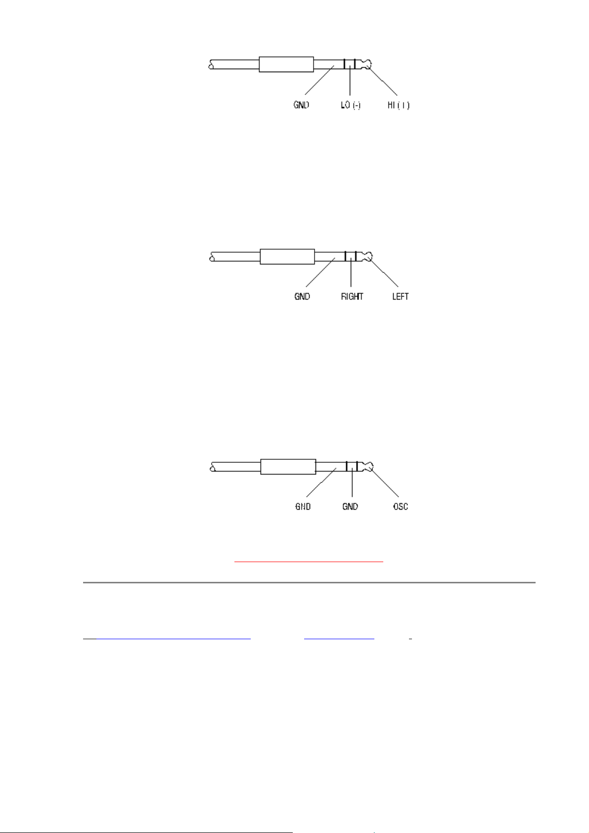
7.4 Y Cables for Boom Operator with tbk mic transmitter.
Click here for DIAGRAMof "Y" Cable
Internal connections of the Boom-Box (022260)
Click here for BOOM BOX Wiring Diagram
860162 860179 860141
Pin No
1
3
2 Red Black 5
GND
White Black 4
Cable Pin No Cable Pin
1 White Tip White
Black 3
2
White Ring
White GND
6
Red
GND
922110 External cable between SX-S extension module and SX-S extension box
Click here for MALE and FEMALE Socket Wiring
Pin No Pair No Cable Designation
12 4 Shield GND
11 4 White -12V
10 4 Yellow +12V
9 3 Orange Guest
8 3 White Roll
7 3 Shield 12V micro
6 2 Red Right from Ext. Box
5 2 White Left from Ext. Box
4
3 1 Brown Right to Ext. Box
2
1 1 Shield GND to Ext. Box
2
1
Shield
White
GND from Ext. Box
Left to Ext. Box
RETURN TO TABLE OF CONTENTS
26.08.2004file://D:\Z_Library\Webcopy\sonosax\SXS\sxsume.html
Page 18

Seite 18 von 22SONOSAX SX/S USER MANUAL
8. FOUR CHANNEL MATRIX MODULE
The four-channel matrix provides four outputs and four tape returns to accomodate 4-track recorders while still
allowing a normal stereo or two-track mix.
Connections to the 4-track device is made through a 10 pin LEMO connector and Lemo to XLR adaptor cable.
8.1 Channel assign Switches:
The first 9 rows of switches select which Input (1 through 9) is directed to which output (A through D). Switch up is
off, switch down is selected. The signal is taken from the channel after the fader and is still available on the Left &
Right mix bus.
For example: To direct channel 1 to Output C, Switch 1-C would be down.
To direct channel 3 to output B, Switch 3-B would be down.
8.2 Master assign Switches:
The switches L & R direct the signals from the L & R Master Faders to Output A through D.
Caution should be exercised if a L or R mixed Output is combined with the output of an individual channel.
A Mono mix can be obtained on a single channel by selecting the same output for both L & R.
8.3 Overload indicators
Overload indicators light whenever a channel is being overdriven.
8.4 Monitor Switches
The IN/OUT A to D Switches direct the Output of the mixer or the Input to the mixer to the monitoring circuit. These
switches are provided with a center Off position.
PFL light on the Master module indicates if one or more of these switches is active.
8.5 Trim pots
The four Trim pots on the circuit board will control the return level.
The module is supplied with a ribbon cable with connectors to attach to J-5 of each of the Input modules.
RETURN TO TABLE OF CONTENTS
26.08.2004file://D:\Z_Library\Webcopy\sonosax\SXS\sxsume.html
Page 19

Seite 19 von 22SONOSAX SX/S USER MANUAL
9. ADDITIONAL AUX MODULE
The Aux Module provides 2 additional Auxiliary Outputs available on two Bantam Jacks on the rear of the mixer.
9.1 AUX Send potentiometers
The signal of each of the Inputs can be directed to the 2 Auxiliary Outputs through the potentiometer pairs marked
1 through 8.
9.2 External Input
If fitted the signal from one external source can be applied to the auxiliary Outputs through the potentiometer pair
marked ext.
9.3 Aux Master control
The potentiometers marked Masters control the final level of the mixed signals to each of the Auxiliary Outputs.
9.4 Talkback Microphone
If fitted, a 3-pin XLR on the rear panel of the mixer can direct the signal from a microphone through either or both
of the pushbuttons to their respective Aux Output. This provides a simple means of slating to an Aux bus. A limiter
circuit prevents overload from the Tbk mic.
9.5 Installation
Attach the necessary XLR and Bantam Jacks to the mixer's rear panel and fit the module into its slot. The module
requires 2 connections to the mix bus ribbon cable. (An additional 26-pin connector must be installed on the mix
bus ribbon cable).
A ribbon connector is provided with connectors to attach to J-5 of each Input module. The signal is taken before
the Fader of the Input modules.
{
J-3 (on both boards) Auxiliary output that connects to the Bantam Jacks
Click here for Drawing of AUX Module Connections
{
J-4 connects to the Tkb mic XLR connector
{
J-5 connects to the external Input XLR connector
{
P-11 (on both boards) controls output symmetry, is factory adjusted and should not be touched.
{
P-12 is the Level control for the Tbk mic.
26.08.2004file://D:\Z_Library\Webcopy\sonosax\SXS\sxsume.html
Page 20

{
p
P-13 is the Gain control for the Tbk mic.
Seite 20 von 22SONOSAX SX/S USER MANUAL
RETURN TO TABLE OF CONTENTS
10. INPUT MONITORING MODULE (SX-V only)
Click here for Picture
The 8-Input monitoring module provides monitoring for 8 different external stereo sources.
Switches 1 through 8: these switches select the input source, the signals are switched to the monitoring circuit.
10.1 Mode switch (upper right corner)
The mode switch defines whether you are listening to the input signal in stereo, mono, only to the left channel on
both headphones or only to the right channel on both headphones. The active mode is always indicated by the
corresponding LED. If in Left / Right mode, pushing the channel switch 1 to 8 on the left will monitor the left
channel ; pushing the switch on the right will monitors the right channel. When you push the left button in L/R
mode the left LED will light and vice versa. Push the mode switch several times to go through all the different
modes.
The slide switch is used to attenuate the input signals.
The 8 Stereo Inputs are made through a 25-pin Sub-D connector on the rear of the mixer.
RETURN TO TABLE OF CONTENTS
11. BALANCED TRANSFORMER OUTPUT MODULE
When installed the electronically balanced outputs are rerouted to a pair of Bantam Jacks. The XLR Outputs are
then transformer coupled Outputs.
11.1 Operating level switch
The nominal operating level can be switched between 1.55 and 4.4 Volts at 600 Ohms.
11.2 Out
ut selector switch
26.08.2004file://D:\Z_Library\Webcopy\sonosax\SXS\sxsume.html
Page 21

A switch will select between the right Output or the AUX Bus.
Seite 21 von 22SONOSAX SX/S USER MANUAL
11.3 Limiter
A switch will select normal operation or a limiter which limits the level to the nominal operating level (1,55 or 4,4
Volts depending on the output level selected).
11.4 Left and Aux / right LEDs
These LEDs illuminate to indicate limiter activity.
RETURN TO TABLE OF CONTENTS
12. SONOSAX SX-V
The SX-V series is derived from the SX-S. The technology and the modules are similar.
The following are all the modifications concerning the SX-V.
12.1 Power supply
The SX-V cannot accept batteries or accumulators inside. However, it can be powered with either 12V DC or
through the mains outlet. The AC voltage range varies from 100 to 260V AC, 40Hz to 60Hz without any
modification, which allows use of the console worldwide.
12.2 Frame
There is only one frame size for the SX-V, that is 10 input modules. Needless to say that you can purchase a
console with less modules, or even replace one of them with a transformer output module.
The handle, the cover and the battery pack have been removed. Two optional brackets allow for an SX-V 19"
rackmount to be fitted.
12.3 Circuit
The INSERT IN, INSERT OUT & LINE OUT connectors have been removed.
The XLR AUX output is connected in parallel with a 1/4" jack.
26.08.2004file://D:\Z_Library\Webcopy\sonosax\SXS\sxsume.html
Page 22

Seite 22 von 22SONOSAX SX/S USER MANUAL
12.4 VCA option
The SX-V modules can be mounted with VCAs instead of plain faders. A DB25 computer type connector allows
control of the VCA with an external DC voltage (for example a video editor). The control voltage ranges from 0 to 5
volts. When used with an external controllers, the faders must be positioned at 0dB.
RETURN TO TABLE OF CONTENTS
13. TIPS ON USING YOUR MIXER
The SONOSAX SX-S has been designed to ensure unsurpassed performance. However, bear in mind that a good
sound recording greatly depends on the dynamics.
We thus recommend the following:
{ Adjust the input gain level at maximum level BEFORE overload, that is with a modulation level between
0dB and +6dB on the modulometer (PFL ON)
{
Input faders should be between 0dB and +10dB.
{
Output faders should be below maximum.
{
Preferably operate at highest possible levels at the first amplification stages or at the mic pre-amp levels.
{ Make sure that interconnection between the SONOSAX SX-S and other equipment is correct and optimal.
{ Optimize operating conditions (location, quality of mic) rather than using the equalizer.
{
Avoid operating with filter at maximum.
{
Switch off unused input modules and make sure that the gain potentiometer is on MIN.
Considering the extensive possibilities offered by your SONOSAX SX-S, this instruction manual may not answer
all questions that may arise during operation of your equipment.
Please contact your nearest SONOSAX dealer for any further nformation.
The specifications mentioned in this manual apply to standard models. SONOSAX SA reserves the right to
NOTE:
modify these characteristicsat any time.
Subject to change without notice
Back to SX-S Page
12/04/99 LG
RETURN TO TABLE OF CONTENTS
26.08.2004file://D:\Z_Library\Webcopy\sonosax\SXS\sxsume.html
 Loading...