

Page 1

Advanced SerialRAID Adapters
User’s Guide and
Maintenance Information
SA33-3285-02
Page 2

Page 3

Advanced SerialRAID Adapters
User’s Guide and
Maintenance Information
SA33-3285-02
Page 4

Third Edition (September 2000)
This softcopy of 14 January 2002 is a minor revision to SA33-3285-02. It contains new technical changes that are not
shown in the printed book. Such changes are shown by a colon (:) to the left of each change. Changes that are also in
the printed book are shown by a vertical line to the left of each change.
The following paragraph does not apply to any country where such provisions are inconsistent with local law:
THIS PUBLICATION IS PRINTED “AS IS” WITHOUT WARRANTY OF ANY KIND, EITHER EXPRESS OR IMPLIED,
INCLUDING, BUT NOT LIMITED TO, THE IMPLIED WARRANTIES OF MERCHANTABILITY OR FITNESS FOR A
PARTICULAR PURPOSE. Some states do not allow disclaimer of express or implied warranties in certain transactions;
therefore, this statement may not apply to you.
This publication could contain technical inaccuracies or typographical errors. Changes are periodically made to the
information herein; these changes will be incorporated in new editions of the publication.
It is possible that this publication may contain reference to, or information about, products (machines and programs),
programming, or services that are not announced in your country. Such references or information must not be
construed to mean that such products, programming, or services will be offered in your country. Any reference to a
licensed program in this publication is not intended to state or imply that you can use only the licensed program
indicated. You can use any functionally equivalent program instead.
© Copyright International Business Machines Corporation 1996, 2000. All rights reserved.
Note to U.S. Government Users — Documentation related to restricted rights — Use, duplication, or disclosure is
subject to restrictions set forth in the GSA ADP Schedule Contract.
Page 5

Contents
Safety Notices........................xv
Definitions of Safety Notices ...................xv
Safety Notice for Installing, Relocating, or Servicing............xv
About This Book ......................xvii
Who Should Use This Book ...................xvii
What This Book Contains ....................xvii
If You Need More Information...................xvii
||
Part 1. User Information ........................1
Web Support Pages......................xviii
Numbering Convention.....................xviii
Chapter 1. Introducing SSA and the Advanced SerialRAID Adapters .....3
Serial Storage Architecture (SSA) ..................3
The Advanced SerialRAID Adapters (type 4–P).............4
Fast-Write Cache Feature ...................5
128 MB Memory Module Feature .................5
Lights of the Advanced SerialRAID Adapters .............6
Port Addresses of the Advanced SerialRAID Adapters ..........6
SSA Adapter ID during Bring-Up ..................6
Chapter 2. Introducing SSA Loops .................7
Loops, Links, and Data Paths ...................7
Simple Loop ........................8
Simple Loop — One Disk Drive Missing ...............9
Simple Loop — Two Disk Drives Missing ..............10
One Loop with Two Adapters in One Using System...........11
One Loop with Two Adapters in Each of Two Using Systems .......12
Two Loops with One Adapter ..................14
Two Loops with TwoAdapters ..................15
Large Configurations ......................16
Switching Off Using Systems ..................17
Switching On Using Systems ..................17
Configuring Devices on an SSA Loop ................18
SSA Link Speed .......................18
Identifying and Addressing SSA Devices ...............19
Location Code Format ....................19
Pdisks, Hdisks, and Disk Drive Identification .............19
SSA Unique IDs ......................21
Rules for SSA Loops ......................22
Checking the Level of the Adapter Microcode..............23
Rules for the Physical Relationship between Disk Drives and Adapters .....24
One Pair of Adapter Connectors in the Loop .............24
Pairs of Adapter Connectors in the Loop – Some Shared Data .......25
Pairs Of Adapter Connectors in the Loop – Mainly Shared Data ......26
iii
Page 6

Reserving Disk Drives .....................27
Fast-Write Cache .......................27
Chapter 3. RAID Functions and Array States .............29
RAID Functions .......................29
Availability ........................29
Disk Drives That Are Not in Arrays ................30
RAID-0 Array States ......................31
Good State ........................31
Offline State........................31
RAID-1 Array States ......................32
RAID-5 Array States ......................33
Good State ........................33
Exposed State .......................33
Degraded State ......................33
Rebuilding State ......................34
Offline State........................34
RAID-5 Array State Flowchart ..................35
RAID-10 Array States .....................36
Good State ........................36
Exposed State .......................36
Degraded State ......................37
Rebuilding State ......................37
Offline State........................37
Unknown State.......................38
Multiple States .......................38
Chapter 4. Using the SSA SMIT Menus ...............39
Getting Access to the SSAAdapters SMIT Menu ............40
Getting Access to the SSA Disks SMIT Menu..............41
Getting Access to the SSA RAID Arrays SMIT Menu ...........43
Chapter 5. Hot Spare Management ................45
Deciding how to Configure Hot Spare Disk Drive Pools ..........45
Choosing How Many Hot Spare Disk Drives to Include in Each Pool ......51
Choosing the Error Threshold (Alarm) Level for a Hot Spare Pool .......51
Rules for Hot Spare Disk Drive Pools ................52
Solving Hot Spare Pool Problems .................53
Chapter 6. Using the RAID Array Configurator ............57
Installing and Configuring SSA RAID Arrays ..............58
Getting Access to the SSA RAID Arrays SMIT Menu ..........59
Adding an SSA RAID Array...................60
Deleting an SSA RAID Array ..................70
Creating a Hot Spare Disk Drive .................72
Changing or Showing the Status of a Hot Spare Pool ..........74
Showing the Disks That Are Protected by Hot Spares ..........77
Listing the Disks That Are in a Hot Spare Pool ............80
Adding a New Hot Spare Pool..................83
Adding Disks to, or Removing Disks from, a Hot Spare Pool........86
iv User’s Guide and Maintenance Information
Page 7

Dealing with RAID Array Problems .................89
Getting Access to the SSA RAID Array SMIT Menu...........90
Identifying and Correcting or Removing Failed Disk Drives ........91
Installing a Replacement Disk Drive ................95
Using Other Configuration Functions ................97
Getting Access to the SSA RAID Array SMIT Menu...........98
Listing All Defined SSA RAID Arrays ...............100
Listing All Supported SSA RAID Arrays ..............101
Listing All SSA RAID Arrays That Are Connected to a RAID Manager ....102
Listing the Status of All Defined SSA RAID Arrays...........104
Listing or Identifying SSA Physical Disk Drives ............108
Listing or Deleting Old RAID Arrays Recorded in an SSA RAID Manager . . . 130
Changing or Showing the Attributes of an SSA RAID Array ........135
Changing Member Disks in an SSA RAID Array ...........137
Changing or Showing the Use of an SSA Disk Drive ..........144
Changing the Use of Multiple SSA Physical Disks ...........147
||
Copying RAID-1 or RAID-10 Arrays ...............148
||
||
|
||
||
|
||
||
||
||
||
||
||
||
|
||
|
||
|
||
||
||
||
||
||
||
||
||
||
||
||
||
Chapter 7. Copying Data from Arrays and from Volume Groups ......149
Copying Data from an Array ...................151
Using the ssaraid Command to Create a RAID-Copy Array from a RAID-1 or
RAID-10 Array......................151
Using SMIT to Create a RAID-Copy Array from a RAID-1 or RAID-10 Array 155
Using the ssa_make_copy Command to Create a RAID Copy from a RAID-1 or
RAID-10 Array......................159
ssa_make_copy Command ...................161
Purpose ........................161
Syntax .........................161
Description........................161
Flags .........................162
Example 1: Copying a Complete Volume Group ...........164
Example 2: Copying One Logical Volume .............165
Example 3: Copying One Logical Volume by Logical Volume Name or by FS
Name ........................166
Example 4: Copying One Logical Volume by Logical Volume Name or by FS
Name (2) .......................168
Example 4: Copying a Complete Volume Group and Recreating the Copy on
Another Using System ...................169
Example 5: Running an Automatic Copy of a Volume Group .......170
ssa_delete_copy Command ...................171
Purpose ........................171
Syntax .........................171
Flags .........................171
SMIT Menus for 3-Way Copy Operations...............172
Getting Access to the Array Copy Services Menu ...........172
Array Copy Services ....................173
Effects of Array Copy on Other SMIT Menus .............186
Change/Show Attributes of an SSA RAID Array ...........186
List Status Of All Defined SSA RAID Arrays .............188
Identify Disks in an SSA RAID Array ...............189
Contents v
Page 8

||
||
Remove a Disk From an SSA RAID Array .............190
Swap Members of an SSA RAID Array ..............191
Chapter 8. Split-Site Management ................193
Configuration of RAID-1 and RAID-10 Arrays .............193
Operation after a Loss of Member Disks ...............194
One Half of the Array Is Not Present ...............195
Array is Offline because Adapter Is Not Known to the Remaining Half of the
Array .........................203
Array is Offline because the Split and Join Procedure Was Not Performed
Correctly .......................205
Chapter 9. Using the SSA Spare Tool ...............209
Chapter 10. Using the Fast-Write Cache Feature ...........211
Fast-Write Cache Card Battery ..................211
Configuring the Fast-Write Cache Feature ..............211
Getting Access to the Fast-Write Menus ..............213
Enabling or Disabling Fast-Write for One Disk Drive ..........214
Enabling or Disabling Fast-Write for Multiple Devices..........215
Bypassing the Cache in a One-Way Fast-Write Network.........217
Dealing with Fast-Write Problems .................218
SRN 42521 .......................218
SRN 42524 .......................220
SRN 42525 .......................220
Chapter 11. SSA Error Logs ..................221
Error Logging ........................221
Summary ........................221
Detailed Description.....................222
Error Logging Management ...................228
Summary ........................228
Detailed Description.....................228
Error Log Analysis ......................229
Summary ........................229
Detailed Description.....................230
Good Housekeeping .....................233
Chapter 12. Using the SSA Command Line Interface for RAID Configurations 235
Command Syntax ......................237
Options ..........................238
Object Types ........................238
Instruct Types........................238
Examples .........................239
Example 1: To Create a RAID-0 Array...............239
Example 2: To Create a RAID-1 Array...............239
Example 3: To Create a RAID-5 Array...............240
Example 4: To Create a RAID-10 Array ..............240
Example 5: To Create a Hot Spare Pool ..............241
Example 6: To List All Defined SSA Objects .............241
vi User’s Guide and Maintenance Information
Page 9

Example 7: To Change an Attribute of an Object ...........242
Example 8: To Exchange a Member Disk Drive of an Existing Array .....242
Example 9: To Make a New System Disk..............243
Example 10: To Delete an Array.................243
SSARAID Command Attributes ..................244
RAID Arrays Creation and Change Attributes ............244
RAID Arrays Change Attributes .................248
Hot Spare Pool Creation and Change Attribute ............249
Physical Disk Drive Change Attributes...............249
Action Attributes (RAID-1, RAID-5, and RAID-10 Only) .........251
||
||
Couple Action Attributes (RAID-1 and RAID-10 Only)..........252
Uncouple Action Attributes (RAID-1 and RAID-10 Only) .........252
Return Codes........................253
Chapter 13. Using the Programming Interface ............255
SSA Subsystem Overview ...................255
Device Drivers ......................255
Interface between the SSA Adapter Device Driver and Head Device Driver 256
Trace Formatting......................256
SSA Adapter Device Driver ...................257
Purpose ........................257
Syntax .........................257
Description........................257
PCI SSAAdapter ODM Attributes ................257
Device-Dependent Subroutines .................258
Summary of SSA Error Conditions ................259
Managing Dumps .....................259
Files ..........................260
IOCINFO (Device Information) SSA Adapter Device Driver ioctl Operation....261
Purpose ........................261
Description........................261
Files ..........................261
SSA_TRANSACTION SSAAdapter Device Driver ioctl Operation.......262
Purpose ........................262
Description........................262
Return Values.......................263
Files ..........................263
SSA_GET_ENTRY_POINT SSA Adapter Device Driver ioctl Operation .....264
Purpose ........................264
Description........................264
Return Values.......................264
Files ..........................264
SSA Adapter Device Driver Direct Call Entry Point............265
Purpose ........................265
Description........................265
Return Values.......................265
ssadisk SSA Disk Device Driver..................266
Purpose ........................266
Syntax .........................266
Configuration Issues ....................266
Contents vii
Page 10

Device Attributes......................270
Device-Dependent Subroutines .................272
Error Conditions ......................274
Special Files .......................276
IOCINFO (Device Information) SSA Disk Device Driver ioctl Operation .....277
Purpose ........................277
Description........................277
Files ..........................277
SSADISK_ISAL_CMD (ISAL Command) SSA Disk Device Driver ioctl Operation 278
Purpose ........................278
Description........................278
Return Values.......................279
Files ..........................280
SSADISK_ISALMgr_CMD (ISAL Manager Command) SSA Disk Device Driver ioctl
Operation ........................281
Purpose ........................281
Description........................281
Return Values.......................282
Files ..........................282
SSADISK_SCSI_CMD (SCSI Command) SSA Disk Device Driver ioctl Operation 283
Purpose ........................283
Description........................283
Return Values.......................284
Files ..........................284
SSADISK_LIST_PDISKS SSA Disk Device Driver ioctl Operation.......285
Purpose ........................285
Description........................285
Return Values.......................286
Files ..........................286
SSA Disk Concurrent Mode of Operation Interface ...........287
Device Driver Entry Point ...................287
Top Kernel Extension Entry Point ................288
SSA Disk Fencing ......................290
SSA Target Mode ......................291
Configuring the SSA Target Mode ................292
Buffer Management .....................293
Understanding Target-Mode Data Pacing..............293
Using SSA Target Mode ...................294
Execution of Target Mode Requests ...............294
SSA tmssa Device Driver ....................295
Purpose ........................295
Syntax .........................295
Description........................295
Configuration Information ...................296
Device-Dependent Subroutines .................296
Errors .........................302
tmssa Special File ......................304
Purpose ........................304
Description........................304
Implementation Specifics ...................304
viii User’s Guide and Maintenance Information
Page 11

Related Information .....................304
IOCINFO (Device Information) tmssa Device Driver ioctl Operation ......305
Purpose ........................305
Description........................305
TMIOSTAT (Status) tmssa Device Driver ioctl Operation..........307
Purpose ........................307
Description........................307
TMCHGIMPARM (Change Parameters) tmssa Device Driver ioctl Operation . . . 308
Purpose ........................308
Description........................308
Part 2. Maintenance Information ....................311
Chapter 14. SSA Adapter Information ...............313
Installing the SSA Adapter ...................313
Cron Table Entries ......................313
Microcode Maintenance ....................314
Checking the ID and Level of the Microcode Package .........314
Maintaining the Adapter Microcode................315
Maintaining the Disk Drive Microcode ...............315
Vital Product Data (VPD) for the SSA Adapter .............316
Adapter Power-On Self-Tests (POSTs) ...............317
Chapter 15. Removal and Replacement Procedures ..........319
Exchanging Disk Drives ....................319
Changing Pdisk and Hdisk Numbers ................326
Removing and Replacing an Advanced SerialRAID Adapter ........327
Removing an SDRAM Module of an Advanced SerialRAID Adapter ......329
Installing an SDRAM Module of an Advanced SerialRAID Adapter ......330
Removing the Fast-Write Cache Option Card of an Advanced SerialRAID Adapter 332
Installing the Fast-Write Cache Option Card of an Advanced SerialRAID Adapter 334
Removing the Battery Assembly from the Fast-Write Cache Option Card of an
Advanced SerialRAID Adapter .................336
Installing a Battery Assembly into the Fast-Write Cache Option Card of an
Advanced SerialRAID Adapter .................338
Part Numbers........................340
Chapter 16. Using the SSA Command Line Utilities ..........341
||
||
||
||
||
||
ssa_sesdld Command .....................341
Purpose ........................341
Syntax .........................341
Description........................341
Flags .........................341
Examples ........................342
ssaadap Command ......................343
Purpose ........................343
Syntax .........................343
Description........................343
Flags .........................343
Contents ix
Page 12

ssacand Command ......................344
Purpose ........................344
Syntax .........................344
Description........................344
Flags .........................344
ssa_certify Command .....................345
Purpose ........................345
Syntax .........................345
Description........................345
Flags .........................345
ssaconn Command ......................347
Purpose ........................347
Syntax .........................347
Description........................347
Flags .........................347
ssa_diag Command......................348
Purpose ........................348
Syntax .........................348
Description........................348
Flags .........................348
Output .........................348
ssadisk Command ......................349
Purpose ........................349
Syntax .........................349
Description........................349
Flags .........................349
ssadload Command......................350
Purpose ........................350
Syntax .........................350
Description........................350
Flags .........................351
Examples ........................351
ssa_ela Command ......................353
Purpose ........................353
Syntax .........................353
Description........................353
Flags .........................353
Output .........................354
ssaencl Command ......................355
Purpose ........................355
Syntax .........................355
Description........................355
Flags .........................355
Examples ........................357
ssa_format Command .....................358
Purpose ........................358
Syntax .........................358
Description........................358
Flags .........................358
Output .........................359
x User’s Guide and Maintenance Information
Page 13

||
||
||
||
||
||
||
ssa_fw_status Command ....................360
Purpose ........................360
Syntax .........................360
Description........................360
Flags .........................360
Output .........................360
Examples ........................360
ssa_getdump Command ....................361
Purpose ........................361
Syntax .........................361
Description........................361
Flags .........................362
Output .........................363
ssaidentify Command .....................364
Purpose ........................364
Syntax .........................364
Description........................364
Flags .........................364
ssa_progress Command ....................365
Purpose ........................365
Syntax .........................365
Description........................365
Flags .........................365
Output .........................365
Examples ........................365
ssa_rescheck Command ....................366
Purpose ........................366
Syntax .........................366
Description........................366
Flags .........................366
Output .........................366
Examples ........................367
Return Codes.......................367
ssa_servicemode Command ...................368
Purpose ........................368
Syntax .........................368
Description........................368
Flags .........................368
Output .........................368
ssa_speed Command .....................369
Purpose ........................369
Syntax .........................369
Description........................369
Flags .........................369
Output .........................370
Examples ........................370
ssavfynn Command......................371
Purpose ........................371
Syntax .........................371
Description........................371
Contents xi
Page 14

Flags .........................371
Output .........................371
ssaxlate Command ......................372
Purpose ........................372
Syntax .........................372
Description........................372
Flags .........................372
Chapter 17. SSA Service Aids ..................373
The Identify Function .....................375
Starting the SSA Service Aids ..................376
Set Service Mode Service Aid ..................378
Link Verification Service Aid ...................383
Configuration Verification Service Aid ................387
Format Disk Service Aid ....................389
Certify Disk Service Aid ....................391
Display/Download Disk Drive Microcode Service Aid ...........393
Link Speed Service Aid ....................396
Service Aid Service Request Numbers (SRNs) .............400
Using the Service Aids for SSA-Link Problem Determination ........400
Example 1. Normal Loops...................401
Example 2. Broken Loop (Cable Removed) .............403
Example 3. Broken Loop (Disk Drive Removed) ...........406
Finding the Physical Location of a Device ..............409
Finding the Device When Service Aids Are Available ..........409
Finding the Device When No Service Aids Are Available.........409
Chapter 18. SSA Problem Determination Procedures..........411
Service Request Numbers (SRNs) .................411
The SRN Table ......................411
Using the SRN Table ....................411
Software and Microcode Errors ..................441
SSA Loop Configurations that Are Not Valid..............441
SSA Maintenance Analysis Procedures (MAPs) ............443
How to Use the MAPs ....................443
MAP 2010: START ......................444
MAP 2320: SSA Link .....................445
MAP 2323: SSA Intermittent Link Error ...............450
MAP 2324: SSA RAID .....................454
MAP 2410: SSA Repair Verification ................475
SSA Link Errors .......................478
SSA Link Error Problem Determination ..............478
Link Status (Ready) Lights ..................481
Service Aid .......................482
Repair Actions ......................482
Part 3. Appendixes..........................483
Appendix. Communications Statements ..............485
xii User’s Guide and Maintenance Information
Page 15

Federal Communications Commission (FCC) Statement..........485
Japanese Voluntary Control Council for Interference (VCCI) Statement .....485
Korean Government Ministry of Communication (MOC) Statement ......485
New Zealand Compliance Statement ................485
International Electrotechnical Commission (IEC) Statement.........486
Avis de conformitéàla réglementation d’Industrie Canada .........486
Industry Canada Compliance Statement ...............486
United Kingdom Telecommunications Requirements ...........486
European Union (EU) Statement .................486
Radio Protection for Germany ..................486
Taiwan Class A Compliance Statement ...............487
Glossary .........................489
Index ..........................493
Contents xiii
Page 16

xiv User’s Guide and Maintenance Information
Page 17

Safety Notices
For a translation of the danger and caution notices contained in this book, see the
Safety Information manual, SA23-2652.
Definitions of Safety Notices
A danger notice indicates the presence of a hazard that has the potential of causing
death or serious personal injury.
This book contains no danger notices.
A caution notice indicates the presence of a hazard that has the potential of causing
moderate or minor personal injury.
This book contains two caution notices. Those caution notices are in this safety section.
An attention notice indicates an action that could cause damage to a program, device,
system, or data.
Safety Notice for Installing, Relocating, or Servicing
Before connecting or removing any cables to or from connectors at the using system,
be sure to follow the steps in the installation or relocation checklist specified in the
Installation and Service Guide for your using system. For safety checks when servicing,
refer to that manual and to the Installation and Service Guide for your subsystem.
CAUTION:
A lithium battery can cause fire, explosion, or a severe burn. Do not recharge,
disassemble, heat above 100°C (212°F), solder directly to the cell, incinerate, or
expose cell contents to water. Keep away from children. Replace only with the
part number specified with your system. Use of another battery might present a
risk of fire or explosion.
The battery connector is polarized; do not try to reverse the polarity.
Dispose of the battery according to local regulations.
Each Advanced SerialRAID Adapter card contains a lithium battery.
CAUTION:
The Fast-Write Cache Option Card contains a nickel-cadmium (NiCad) battery. To
avoid possible explosion, do not incinerate the battery. Exchange it only with a
manufacturer-approved part. Recycle or discard the battery as instructed by local
regulations and where recycling facilities exist.
xv
Page 18

xvi User’s Guide and Maintenance Information
Page 19

About This Book
Who Should Use This Book
This book is for people who operate or service a RISC system that contains one or
more Advanced SerialRAID Adapters. To follow the instructions in this book, you should
be familiar with the basic operational procedures for a RISC system.
What This Book Contains
Part 1 of this book is mainly for the user. It describes:
v The Advanced SerialRAID Adapters
v SSA loops
v The RAID facilities that are provided by the adapter
v How to use the SSA SMIT menus
v How to use the RAID configuration utility to configure arrays of SSA disk drives, and
how to deal with problems such as the failure of a disk drive in a RAID array
v How to use the SSA Spare Tool
v How to configure the Fast-Write feature
v SSA error logs
v How to use the SSA Command Line Interface
v How to use the programming interface
Part 2 of this book is mainly for service representatives. It describes:
v General technical topics about the Advanced SerialRAID Adapters
v Removal and replacement procedures
v How to use the SSA Command Line Utilities
v The SSA service aids
v Problem determination procedures, including Service Request Numbers (SRNs) and
Maintenance analysis procedures (MAPs)
The appendix contains the communications statements for the adapter.
A glossary and an index are provided.
If You Need More Information
The Problem Solving Guide and Reference, SC23-2204, is the first book you should
use if you have a problem with your system.
Other books that you might need are:
v The operator guide for your system
v Diagnostic Information for Multiple Bus Systems, SA38-0509
v Technical Reference for your adapter
xvii
Page 20

Web Support Pages
|
|
|
|
|
When you are installing an SSA device or subsystem, upgrading your SSA subsystem,
or doing preventive maintenance on your SSA subsystem, refer to the web page shown
here. This web page provides access to the latest SSA publications, micorocde, and
support information for the using system, SSA adapters, and SSA subsystem.
|
http://www.storage.ibm.com/hardsoft/products/ssa
|
Numbering Convention
In this book:
KB means 1 000 bytes.
MB means 1 000 000 bytes.
GB means 1 000 000 000 bytes.
xviii User’s Guide and Maintenance Information
Page 21

Part 1. User Information
1
Page 22

2 User’s Guide and Maintenance Information
Page 23

Chapter 1. Introducing SSA and the Advanced SerialRAID Adapters
This chapter describes:
v Serial storage architecture (SSA).
v The Advanced SerialRAID Adapter and the Advanced SerialRAID Plus Adapter.
Physically, the two types of adapter are the same. The Advanced SerialRAID Plus
Adapter, however, provides additional functions.
In this book, the name “Advanced SerialRAID Adapter” is used both for the Advanced
SerialRAID Adapter and for the Advanced SerialRAID Plus Adapter, unless otherwise
stated.
Serial Storage Architecture (SSA)
Serial Storage Architecture (SSA) is an industry-standard interface that provides
high-performance fault-tolerant attachment of I/O storage devices. In SSA subsystems,
transmissions to several destinations are multiplexed; the effective bandwidth is further
increased by spatial reuse of the individual links. Commands are forwarded
automatically from device to device along a loop until the target device is reached.
Multiple commands can be travelling around the loop simultaneously. SSA retains the
SCSI-2 commands, queuing model, and status and sense bytes.
3
Page 24
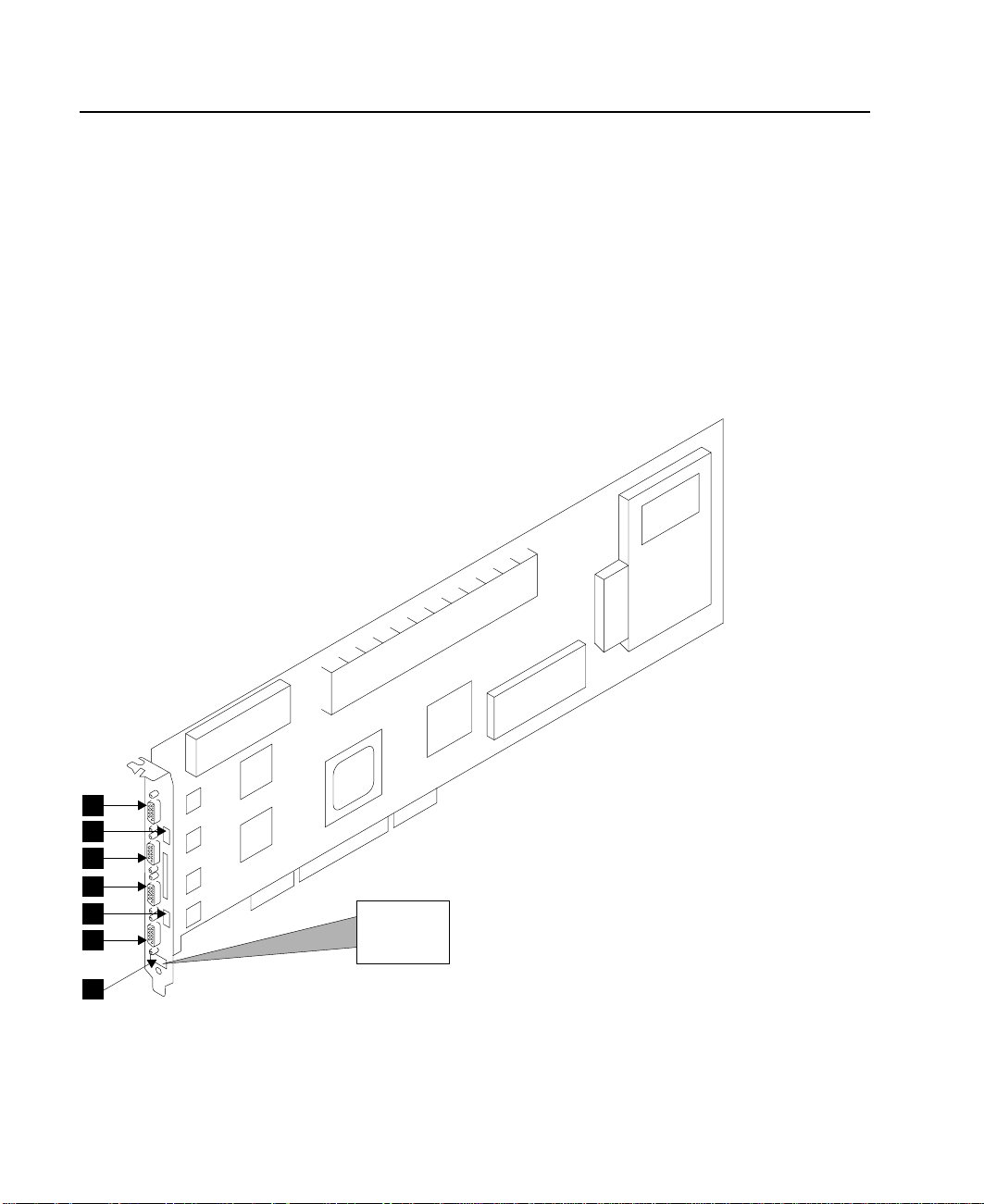
The Advanced SerialRAID Adapters (type 4–P)
The Advanced SerialRAID Adapters (see Figure 1) are 40-MB-per-second Serial
Storage Architecture (SSA), Peripheral Component Interconnect (PCI) adapters that
serve as the interface between systems that use PCI architecture and devices that use
SSA. These adapters provide support for two SSA loops. Each loop can contain a
maximum of eight pairs of adapter connectors and a maximum of 48 disk drives. See
also “Rules for SSA Loops” on page 22.
1 Connector B2 5 Green light
2 Green light 6 Connector A1
3 Connector B1 7 Type-number label
4 Connector A2
1
2
3
4
5
6
7
Figure 1. An Advanced SerialRAID Adapter Card (Type 4–P)
4 User’s Guide and Maintenance Information
4-P
Page 25

Note: In the SSA service aids, this adapter is called “IBM SSA 160 SerialRAID Adapter
(14109100)”.
The adapter card has four SSA connectors that are arranged in two pairs. Connectors
A1 and A2 are one pair; connectors B1 and B2 are the other pair.
The SSA links must be configured as loops. Each loop is connected to a pair of
connectors at the SSA adapter card. These connectors must be a valid pair (that is, A1
and A2 or B1 and B2); otherwise, the disk drives on the loop are not fully configured,
and the diagnostics fail. Operations to all the disk drives on a particular loop can
continue if that loop breaks at any one point.
This adapter also contains array management software that provides RAID functions to
control the arrays of the RAID subsystem (see also Chapter 3, “RAID Functions and
Array States” on page 29). An array can contain several member disk drives. Each
array is handled as one disk by the operating system. The array management software
translates requests to this disk into requests to the member disk drives. Although this
adapter is a RAID adapter, it can be configured so that all, some, or none of the disk
drives that are attached to it are member disk drives of arrays.
The Advanced SerialRAID Adapter can be connected, by way of one or two SSA loops,
to other SSA adapters. These adapters can be either in the same using system, or in
separate using systems. (See “Rules for SSA Loops” on page 22 for details of valid
configurations.)
Fast-Write Cache Feature
An optional 32 MB Fast-Write Cache feature is available for the Advanced SerialRAID
Adapter. This feature improves performance for jobs that include many write operations.
128 MB Memory Module Feature
An optional 128 MB dual inline memory module (DIMM) feature is available. This
feature is recommended for two-way fast-write operations.
Chapter 1. Introducing SSA and the Advanced SerialRAID Adapters 5
Page 26

Lights of the Advanced SerialRAID Adapters
Each pair of connectors has a green light that indicates the operational status of its
related loop:
Status of Light Meaning
Off Both SSA connectors are inactive. If disk drives or other SSA
adapters are connected to these connectors, either those disk drives
or adapters are failing, or their SSA links are not active.
Permanently on
Both SSA links are active (normal operating condition).
Slow Flash Only one SSA link is active.
Port Addresses of the Advanced SerialRAID Adapters
The port addresses used in some SRNs that relate to these adapters can be numbers 0
through 3. They correspond to the port connectors on the SSA adapter:
0 = Connector A1
1 = Connector A2
2 = Connector B1
3 = Connector B2
SSA Adapter ID during Bring-Up
All adapters that can be used on RISC using systems generate a three-digit
configuration program indicator number. During system bring-up, this indicator number
appears on the three-digit display of the using system. The numbers are:
80C Advanced SerialRAID Adapter (type 4-P) is being identified or configured.
6 User’s Guide and Maintenance Information
Page 27

Chapter 2. Introducing SSA Loops
This chapter describes the principles of SSA loops, how SSA devices are known to the
system programs, and the rules that you must observe when you configure your SSA
loops.
Loops, Links, and Data Paths
In the simplest SSA configuration, SSA devices are connected through two or more
SSA links to an SSA adapter that is located in a using system. The devices, SSA links,
and SSA adapter are configured in loops. Each loop provides a data path that starts at
one connector of the SSA adapter and passes through a link (SSA cable) to the
devices. The loop continues through the devices, then returns through another link to a
second connector on the SSA adapter.
The maximum permitted length for an external copper cable that connects two SSA
nodes (for example, disk drives) is 25 meters (82 feet).
The maximum permitted length for an external fiber optic cable that connects two SSA
nodes (for example, disk drives) is 10 kilometers (32800 feet). Some devices, however,
can operate only at shorter distances. See your subsystem documentation for details.
Details of the rules for configuring SSA loops are given for each SSA adapter in “Rules
for SSA Loops” on page 22.
7
Page 28
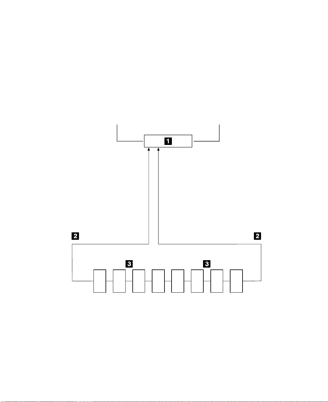
Simple Loop
Figure 2 shows a simple SSA loop. The devices that are attached to the SSA adapter
card 1 are connected through SSA links 2. These SSA links are configured as a
loop. Data and commands to a particular device pass through all other devices on the
link between the adapter and the target device.
Data can travel in either direction round the loop. The adapter can, therefore, get
access to the devices 3 (disk drives in this example) through two data paths. The
adapter always, however, uses the path that has the fewest interconnecting devices
between the adapter and the destination device. The using system cannot detect which
data path is being used.
Using system
A1 A2 B1 B2
Disk1Disk2Disk3Disk4Disk5Disk6Disk7Disk
Figure 2. Simple Loop
8 User’s Guide and Maintenance Information
8
Page 29
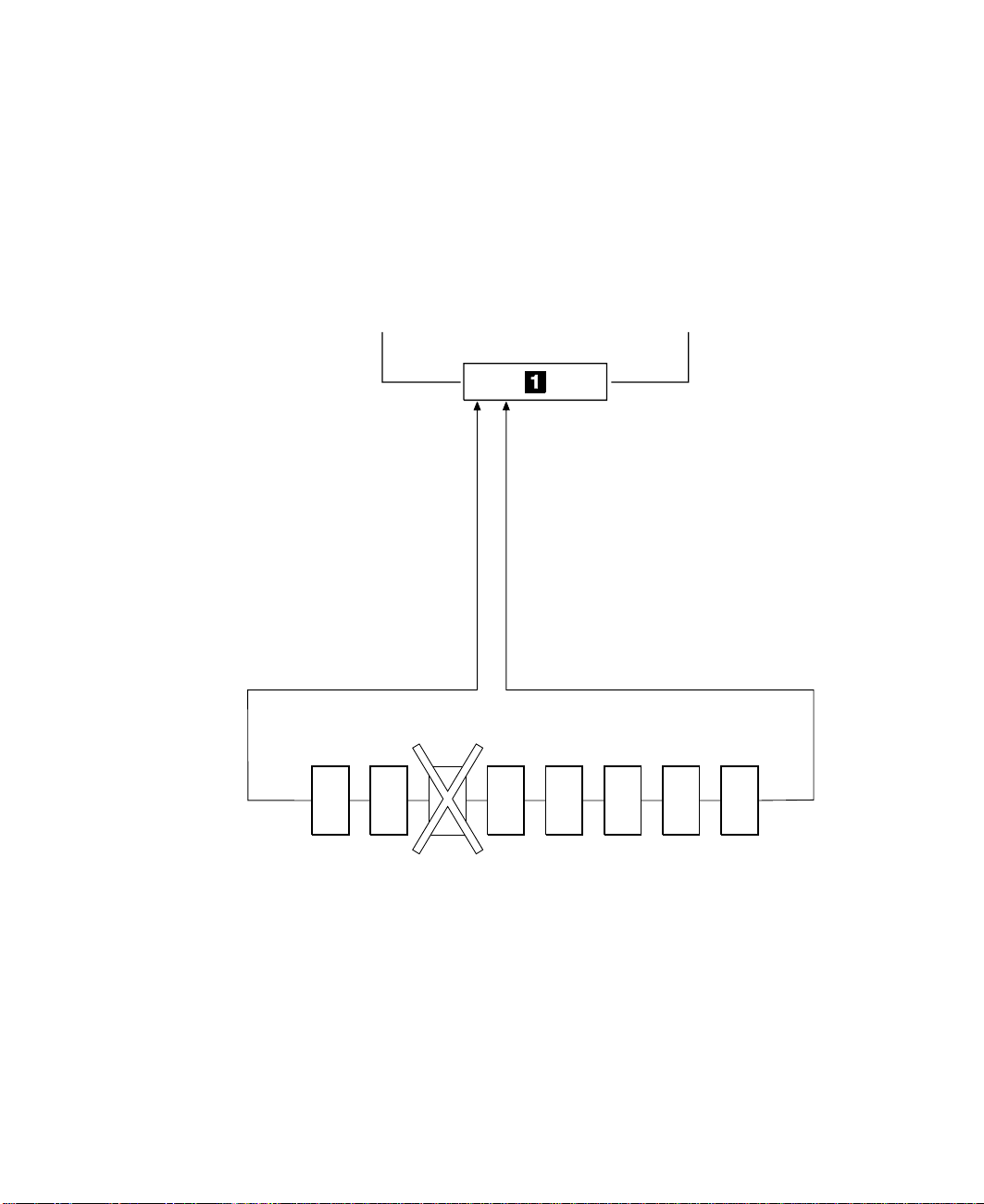
Simple Loop — One Disk Drive Missing
If a disk drive fails, or is switched off, the loop is broken, and one of the data paths to a
particular disk drive is no longer available. The disk drives on the remainder of the loop
continue to work, but an error is reported to the system. The adapter now uses the
alternative path to some of the devices.
In Figure 3, disk drive number 3 has failed. Disk drives 1 and 2 can communicate with
the using system only through connector A1 of the SSA adapter. Disk drives 4 through
8 can communicate only through connector A2 of the SSA adapter.
A1 A2 B1 B2
Using system
Disk1Disk2Disk3Disk4Disk5Disk6Disk7Disk
Figure 3. Simple Loop with One Disk Drive Missing
8
Chapter 2. Introducing SSA Loops 9
Page 30
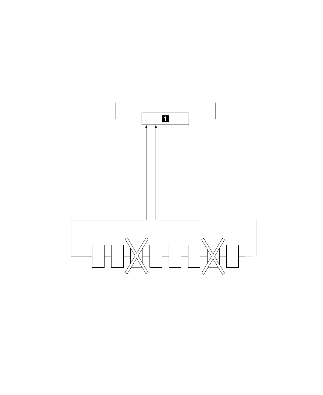
Simple Loop — Two Disk Drives Missing
If two or more disk drives are switched off, fail, or are removed from the loop, some
disk drives might become isolated from the SSA adapter.
In Figure 4, disk drives 3 and 7 have been removed. Disk drives 1 and 2 can
communicate with the using system only through connector A1 of the SSA adapter. Disk
drive number 8 can communicate with the using system only through connector A2 of
the SSA adapter. Disk drives 4, 5, and 6 are isolated from the SSA adapter.
Using system
A1 A2 B1 B2
Disk1Disk2Disk3Disk4Disk5Disk6Disk7Disk
Figure 4. Simple Loop with Two Disk Drives Missing
10 User’s Guide and Maintenance Information
8
Page 31

One Loop with Two Adapters in One Using System
In Figure 5, the loop contains two SSA adapters 1 and 2 that are both in the same
using system. In this configuration, all the disk drives can still communicate with the
using system if one SSA adapter fails.
Using System
A1 A2 B1 B2 A1 A2 B1 B2
1
Disk16Disk15Disk14Disk
13
Disk1Disk2Disk3Disk
4
Disk12Disk11Disk10Disk
Disk5Disk6Disk7Disk
2
Figure 5. One Loop with Two Adapters in One Using System
9
8
Chapter 2. Introducing SSA Loops 11
Page 32

One Loop with Two Adapters in Each of Two Using Systems
If the loop contains four SSA adapters, with two adapters in each of two using systems,
disk drives become isolated if they are connected between the two adapters of one
using system, and both those adapters fail, or are held reset, but remain powered on.
Bypass Note: Your SSA Disk Subsystem, or SSA Disk Enclosure, might contain
bypass cards. Each bypass card can switch the internal strings of the
subsystem, or enclosure, if it detects that neither of its connectors is
connected to a powered-on SSA adapter or device. Therefore, if the two
SSA adapters fail, or are held reset, but remain powered on, the bypass
card does not operate, and the disk drives become isolated. (For more
information about bypass cards, see the publications for your disk
subsystem or enclosure.)
In Figure 6, SSA adapters 1 and 2 are in using system 1; SSA adapters 3 and
4 are in using system 2. In each using system, the two adapters are connected to
each other.
If the two SSA adapters of either using system fail, or are held reset, but remain
powered on, all the disk drives can still communicate with the other using system.
Using System 1
A1 A2 B1 B2 A1 A2 B1 B2
1
Disk16Disk15Disk14Disk
13
Disk1Disk2Disk3Disk
4
B2 B1 A2 A1 B2 B1 A2 A1
3
Using System 2
Figure 6. One Loop, Two Adapters in Each of Two Using Systems
Disk12Disk11Disk10Disk
Disk5Disk6Disk7Disk
2
4
9
8
12 User’s Guide and Maintenance Information
Page 33

If, however, disk drives are connected into the link between two SSA adapters that are
in the same using system, those disk drives become isolated if both SSA adapters fail,
or are held reset, but remain powered on (see also “Bypass Note” on page 12). In
Figure 7, disk drives 13 through 16 have been connected between the SSA adapters in
using system 1. If both adapters fail, or are held reset, but remain powered on, disk
drives 1 through 12 can still communicate with using system 2. Disk drives 13 through
16, however, cannot communicate with using system 2, because their data paths are
through the adapters in using system 1. When using system 1 is rebooted, disk drives
13 through 16 remain unavailable for a long time.
Using System 1
A1 A2 B1 B2 A1 A2 B1 B2
1
Disk16Disk15Disk14Disk
13
Disk12Disk11Disk10Disk
Disk1Disk2Disk3Disk
4
B2 B1 A2 A1 B2 B1 A2 A1
3
Using System 2
Figure 7. Disk Drives Isolated by Failing Using System
Disk5Disk6Disk7Disk
2
9
8
4
Chapter 2. Introducing SSA Loops 13
Page 34

Two Loops with One Adapter
If only one SSA adapter is contained in the SSA loops, the adapter can provide support
for up to 96 disk drives (a maximum of 48 per loop).
Figure 8 shows an example configuration that has two loops and one adapter:
Adapter
Figure 8. Two Loops with One Adapter
SSA Disk Drives
14 User’s Guide and Maintenance Information
Page 35

Two Loops with Two Adapters
The two adapters can provide support for up to 96 SSA disk drives (a maximum of 48
per loop).
Figure 9 shows an example configuration that has two loops and two adapters:
Adapter
SSA Disk Drives
Figure 9. Two Loops with Two Adapters
Adapter
Chapter 2. Introducing SSA Loops 15
Page 36

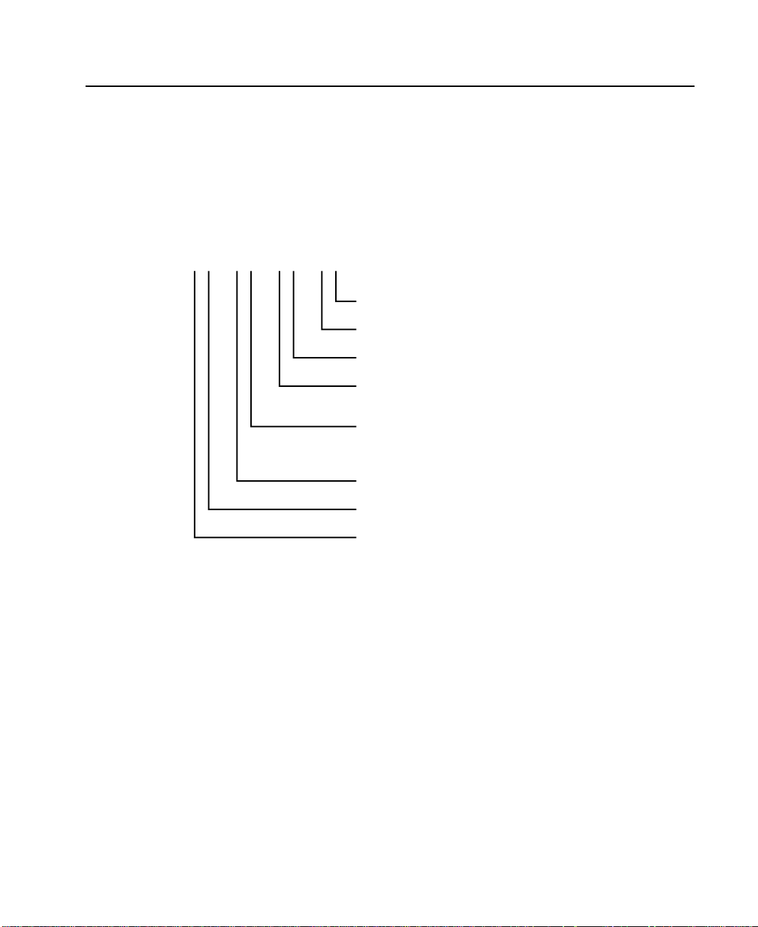
Large Configurations
Up to eight SSA adapters can be connected in a particular SSA loop, and up to 48 disk
drives can be included in that loop. Figure 10 shows an example of a large
configuration that has eight adapters in eight using systems.
AdapterAdapterAdapter
Adapter
SSA Disk Drives
Adapter Adapter Adapter
Adapter
Figure 10. A Large Configuration of Thirty-Two Disk Drives Connected to Eight SSA
Adapters in Eight Using Systems
Figure 11 shows an example of a large configuration that has eight adapters in four
using systems.
Adapter Adapter
Using System A
Adapter Adapter
Using System B
SSA Disk Drives
Using System C
Adapter Adapter
Using System D
Adapter Adapter
Figure 11. A Large Configuration of Thirty-Two Disk Drives Connected to Eight SSA
Adapters in Four Using Systems,
16 User’s Guide and Maintenance Information
Page 37

Switching Off Using Systems
Be careful if you want to switch off one or more using systems in a large configuration.
If any disk subsystem in the configuration does not use bypass cards, some using
systems might lose access to disk drives if you:
v Switch off more than one using system at a time
v Switch off a using system when a disk drive has failed.
Note: For more information about bypass cards, see the publications for your disk
subsystems or enclosures.
Switching On Using Systems
When you switch on using systems of a large configuration, ensure that each using
system configures all the disk drives in the SSA loop. You can switch on each using
system and give the cfgmgr command to ensure that all the disk drives are configured.
If, however, you need your pdisk assignments to be constant between using systems,
follow the procedures given in “Configuring Devices on an SSA Loop” on page 18.
Chapter 2. Introducing SSA Loops 17
Page 38

Configuring Devices on an SSA Loop
If an SSA loop contains three or more SSA adapters that are installed in two or more
using systems, you must ensure that all those using systems are switched on, and that
all the disk drives in all those using systems are configured, as follows:
v If all the using systems are switched off (Micro Channel or PCI):
1. For each Micro Channel system:
a. Set Secure mode on each using system.
b. Switch on all the using systems.
c. Wait for 200 to be displayed on the operator panel of each system.
For each PCI system:
a. Switch on one using system only.
b. Wait for the first display (logo) to appear on the screen. Press F1
immediately. The using system goes into System Management Services
mode.
2. When each using system is in the state described in the preceding steps:
– For Micro Channel systems, set Normal mode to continue the boot process.
– For PCI systems, press F10 (Exit) to continue the boot process.
v If one or more using systems are switched on (Micro Channel or PCI):
1. Switch on the remaining using systems.
2. On each using system:
a. Run the cfgmgr command to configure all the disk drives.
b. Manually vary on the volume groups and mount the file systems as required.
SSA Link Speed
Some SSA devices can run at 20 MB per second; others can run at 40 MB per second.
Both types of devices can exist in a particular configuration, but for best performance all
links should run at the same speed. Two types of SSA cable are available:
v 20 MB per second SSA cables (color coded black)
v 40 MB per second SSA cables (color coded blue).
The speed at which a link runs is automatically agreed between its two nodes. Under
some fault conditions, a link that normally runs at 40 MB per second might run at
20 MB per second. The automatic run_ssa_link_speed diagnostic searches for pairs
of 40-MB-per-second nodes that are running at only 20 MB per second. This diagnostic
is started by an entry in the cron table. If you are using 20-MB-per-second cables to
connect 40-MB-per-second SSA nodes, delete the run_ssa_link_speed entry from the
cron table. This action prevents the logging of errors that can be solved only by the
installation of 40-MB-per-second cables.
18 User’s Guide and Maintenance Information
Page 39
Identifying and Addressing SSA Devices
This section describes how SSA adapters and devices are known to the using system
programs.
Location Code Format
Location codes identify the locations of adapters and devices in the using system and
its attached subsystems and devices. These codes are displayed when the diagnostic
programs isolate a problem. For information about the location codes that are used by
the using system, see the Operator Guide for the using system.
AB CD EF GH---
Unused
Unused
Unused
P = Physical disk drive
L = Logical disk drive
Adapter position
(number of the slot, 1 through 8,
containing the SSA adapter)
System I/O bus identifier
Expansion adapter position
Expansion drawer
The location code shows only the position of the SSA adapter in the using system and
the type of device that is attached. The location of the device within the SSA loop must
be found by use of a service aid. The service aids use the IEEE-standard 16-digit
unique ID of the device.
Pdisks, Hdisks, and Disk Drive Identification
The physical disk drives (pdisks) in an SSA subsystem can be configured as logical
units (LUNs). A LUN is also known as an hdisk, and can consist of one or more
physical disk drives. An hdisk in an SSA subsystem might, therefore, consist of one
pdisk or several pdisks.
The configuration software allocates an identification (hdisk and pdisk number) to each
disk drive during the configuration of the SSA link. The disk drives do not have fixed
physical addresses.
The numeric identifiers of pdisks, hdisks, and the disk drive slots are not related to each
other. For example, pdisk1 is not necessarily in slot 1 of the physical unit in which it is
installed.
Chapter 2. Introducing SSA Loops 19
Page 40

The configuration software first recognizes the disk drive by its machine-readable serial
number. The serial number of the disk drive is also displayed by the service aids. The
service aids show the number as the last eight digits of the IEEE SSA Unique ID.
Service actions are always related to physical disk drives. For this reason, errors that
occur on SSA disk drives are always logged against the physical disk drive (pdisk).
|
|
|
|
If a disk drive that has been formatted on a machine of a particular type (for example, a
personal computer) is later installed into a using system that is of a different type (for
example, a large host system), that disk drive is configured only as a pdisk during the
configuration of the using system.
20 User’s Guide and Maintenance Information
Page 41

SSA Unique IDs
Each SSA device has a specific identifier that is not used by any other SSA device in
the whole world. This identifier is called the IEEE SSA Unique ID (UID) of the device. It
is written into the device during manufacture.
The full UID consists of 16 characters. The label on the side of a disk drive shows the
full UID. The label on the front of a disk drive shows the serial number of the disk drive.
The serial number is actually part of the UID. Also part of the UID, the Connection
Address consists of the LUN name and the device-type identifier. The software uses
this information to access the device.
where:
XXXXXX = IEEE Organization Identifier (manufacturer)
NNNNNN = Product / ID (assigned unique number)
LL = LUN (always 00 for a LUN device)
D=Device type:
Full UID 0000XXXXXXNNNNNN
Disk drive serial number XXNNNNNN
Connection Address XXXXXXNNNNNNLLD
(D for an SSA Physical disk drive)
(E for a fast-write logical disk)
(F for a RAID-0 array)
(K for a RAID-5 array)
You might need to know the UID of a disk drive if you want to use the mkdev
command to give that disk drive a specific hdisk number.
Chapter 2. Introducing SSA Loops 21
Page 42

Rules for SSA Loops
For SSA loops that include an Advanced SerialRAID Adapter (type 4–P), the following
rules apply:
v Each SSA loop must be connected to a valid pair of connectors on the SSA adapter
v A maximum of one pair of adapter connectors can be connected in a particular SSA
v All member disk drives of an array must be on the same SSA loop.
|
|
|
|
|
|
|||
|||
|||
||
v A maximum of 48 SSA disk drives can be connected in a particular SSA loop.
v If an SSA adapter that is in a two-way configuration is connected to two SSA loops,
v Each SSA loop can be connected to no more than two adapters on any one using
v The number of adapters that are supported in an SSA loop is determined by whether
Table 1. Number of Adapters that are Supported in an SSA Loop
Array Type Number of
Non-RAID 8 Advanced SerialRAID Adapter
RAID-0 1 Advanced SerialRAID Adapter
RAID-1 2 Advanced SerialRAID Adapter at microcode level above 5000
RAID-5 2 Advanced SerialRAID Adapter
RAID-10 2 Advanced SerialRAID Adapter at microcode level above 5000
Fast-Write 1 Advanced SerialRAID Adapter at microcode level below 5000
(that is, either connectors A1 and A2, or connectors B1 and B2).
loop.
and a second adapter is connected to each loop, both loops must be connected to
the same second adapter.
system.
any disk drives are configured for RAID or fast-write operations, and by the type of
adapter (see Table 1).
Type of Adapters Allowed
Adapters in
Loop
PCI SSA Multi-Initiator/RAID EL Adapter
Micro Channel SSA Multi-Initiator/RAID EL Adapter
PCI SSA Multi-Initiator/RAID EL Adapter
Micro Channel SSA Multi-Initiator/RAID EL Adapter
2 Advanced SerialRAID Adapter at microcode level above 5000
See the SSA Adapters: User’s Guide and Maintenance Information manual,
SA33-3272 (Version 01 or above) for more information about the level of code that is
required in the Micro Channel SSA Multi-Initiator/RAID EL Adapter (type 4–M) or the
PCI SSA Multi-Initiator/RAID EL Adapter (type 4–N).
22 User’s Guide and Maintenance Information
Page 43

Checking the Level of the Adapter Microcode
If you need to check the level of the adapter microcode:
1. Type, on the command line:
lscfg -vl ssan
where ssan is the name of the adapter whose microcode you are checking; for
example, ssa0.
A list of vital product data (VPD) is displayed.
|
2. Find ROS Level and ID, for example, 5000.
Chapter 2. Introducing SSA Loops 23
Page 44

Rules for the Physical Relationship between Disk Drives and Adapters
The physical relationship between the disk drives and the adapters in an SSA loop can
affect the performance of the subsystem. The following rules help you to get best
performance from your subsystem.
One Pair of Adapter Connectors in the Loop
The following sequence enables you to determine the best relationship between the
disk drives and the adapter on an SSA loop that contains only one pair of adapter
connectors.
1. Determine which data is accessed most frequently.
2. Assign that data to those disks drives that are farthest (round the loop) from the
adapter connectors. By doing this action, you prevent the activity of the busiest disk
drive from obstructing the data path to the other disk drives.
For example, the loop that is shown in Figure 12 contains 16 disk drives, and the
adapter connectors are between disk drives 1 and 16. The most-frequently-accessed
data, therefore, should be on disk drives 8 and 9.
Disk1Disk2Disk3Disk
4
Adapter
14
Disk
13
Disk
Figure 12. One Pair of Connectors in the Loop
Disk
16
Disk
15
Disk5Disk6Disk7Disk
8
10
Disk
9
Disk
12
Disk
11
Disk
24 User’s Guide and Maintenance Information
Page 45

Pairs of Adapter Connectors in the Loop – Some Shared Data
The following sequence enables you to determine the best relationship between the
disk drives and the adapter on an SSA loop that contains two or more pairs of adapter
connectors. Some of the disk drives share data access with other disk drives.
1. For each pair of connectors, identify all the data that the loop is to access.
2. For each pair of connectors, identify the data that the loop is to access most
frequently.
3. Assign the data for each pair of adapter connectors to the disk drives that are
connected immediately next to the pair of connectors in the loop. Assign the
most-frequently-accessed data to those disk drives that are farthest from the
adapter connectors. By doing this action, you prevent the activity of the busiest disk
drive from obstructing the data path to the other disk drives.
For example, the loop that is shown in Figure 13 contains 16 disk drives. The
connectors of adapter A are between disk drives 1 and 16, and the connectors of
adapter B are between disks 8 and 9. Therefore:
v Adapter A should access disk drives 1 through 4 and disk drives 13 through 16. The
most-frequently-accessed data should be on disk drives 4 and 13.
v Adapter B should access disk drives 5 through 8 and disk drives 9 through 12. The
most-frequently-accessed data should be on disk drives 5 and 12.
Disk1Disk2Disk3Disk
4
Adapter A
14
Disk
13
Disk
Figure 13. Pairs of Connectors in the Loop – Some Shared Data
Disk
16
Disk
15
Disk5Disk6Disk7Disk
Disk
Disk
12
11
Chapter 2. Introducing SSA Loops 25
Disk
10
8
Adapter B
Disk
9
Page 46

Pairs Of Adapter Connectors in the Loop – Mainly Shared Data
The following sequence enables you to determine the best relationship between the
disk drives and the adapter, or adapters, on an SSA loop that contains two or more
pairs of adapter connectors. Most of the disk drives share data access with each other.
1. Determine which data is shared between the pairs of adapter connectors.
2. Assign this data to the disk drives that are equally spaced between the sharing
pairs of adapter connectors.
For example, the loop that is shown in Figure 14 contains 16 disks and four adapters.
In this loop:
v The pairs of adapter connectors should be spaced between the disk drives.
v Data that is shared by adapters A and B should be put onto disk drives 1 through 4.
v Data that is shared by adapters B and C should be put onto disk drives 5 through 8.
Adapter B
Disk1Disk2Disk3Disk
4
Adapter A
14
Disk
13
Adapter D
Disk
Figure 14. Pairs of Connectors in the Loop – Mainly Shared Data
Note: For configurations such as that shown here, we recommend that the adapters be
installed in separate using systems. Otherwise, disk drives can become isolated
should both adapters fail, or be held reset, in one of the using systems. See
“One Loop with Two Adapters in One Using System” on page 11 and “One Loop
with Two Adapters in Each of Two Using Systems” on page 12 for more
information.
If two using systems are switched off, disk drives can become isolated if the
SSA subsystem does not have bypass cards (see “Bypass Note” on page 12). If
more than one using system is rebooted at the same time, disk drives can
become isolated while the boot is running.
Disk
16
Disk
15
Disk5Disk6Disk7Disk
8
10
Disk
9
Disk
12
Disk
11
Disk
Adapter C
26 User’s Guide and Maintenance Information
Page 47

Reserving Disk Drives
The Advanced SerialRAID Adapter, the Micro Channel SSA Multi-Initiator/RAID EL
Adapter, and the PCI SSA Multi-Initiator/RAID EL Adapter implement reservation by
using commands that are sent directly from adapter to adapter. They do not use the
SCSI reservation command. The advantages of this method are:
|
v System software can read the Physical Volume ID (PVID) from a reserved disk drive.
v It is possible to use the ssa_rescheck command to determine which adapter is
holding a reservation to a disk drive.
v The diagnostics can detect particular failure conditions on reserved disk drives that
they cannot detect with the other reservation method.
v Fencing can be used on a reserved disk drive.
v Node_number locking is supported. With node_number locking, the disk drive is not
locked to an adapter, but rather to a using system. To enable a disk drive to be
locked to a using system, each using system in an SSA network must have a unique
node number. The node number is stored as the node_number attribute of ssar. It
can be queried with the lsattr command and set by using the chdev command. The
ssavfynn command (described in “ssavfynn Command” on page 371) can be used to
verify that no duplicate node numbers exist.
v If a reservation is challenged (that is, a node that does not hold the reservation
attempts to access a reserved SSA logical disk), the adapter verifies that a valid path
still exists to the node that is holding the reservation. If no path exists, the
reservation is removed, and the new node is allowed access to the disk drive.
Therefore, if an adapter is used to reserve a disk drive, and is then disconnected or
powered off, that disk drive becomes effectively unreserved.
Fast-Write Cache
SSA adapters that are on SSA loops of up to two SSA adapters can use the Fast-Write
cache feature. For a two-way configuration, the two adapters can be in the same, or in
different, using systems. Fast-write functions can be enabled for single disk drives or for
RAID arrays. Performance improvements are related to the type of disk drive (single
disk or RAID array type) and the workload. If two-way fast-write functions are used in a
two-host system configuration, the performance improvements are greater when
concurrent access is not permitted to disk drives. When concurrent access is permitted,
performance improvements are less.
Chapter 2. Introducing SSA Loops 27
Page 48

28 User’s Guide and Maintenance Information
Page 49

Chapter 3. RAID Functions and Array States
This chapter describes the RAID functions and the states of RAID arrays.
RAID Functions
Redundant Array of Independent Disks (RAID) technology provides:
v Larger disk size
v Immediate availability and recovery of data
v Redundancy of data at a level that you can choose.
RAID technology stores data across groups of disk drives that are known as arrays.
These arrays are contained in array subsystems, which can be configured with one or
more arrays. All arrays, except RAID-0 arrays, can provide data redundancy that
ensures that no data is lost if one disk drive in the array fails.
|
|
|
|
Availability
An Advanced SerialRAID Adapter, which uses microcode below level 5000, provides
RAID-0 and RAID-5 functions to control the arrays of the RAID subsystem. An
Advanced SerialRAID Plus Adapter, which uses microcode at or above level 5000,
provides RAID-0, RAID-1, RAID-5, and RAID-10 functions.
The main characteristics of the various RAID types are as follows:
v RAID-0 provides data striping across disk drives, but provides no added protection
against loss of data.
v RAID-1 provides data mirroring across two member disk drives to protect against
loss of data.
v RAID-5 provides data striping with parity data across disk drives to provide protection
against loss of data.
v RAID-10 provides data striping and data mirroring across disk drives to provide
protection against loss of data.
Availability is an important consideration that can affect the way you configure your
arrays. It is the ability of a system to continue operating, although one or more of its
components have failed.
v RAID-0 provides data availability equivalent to that of a standard disk drive, but with
better performance for long data transfer operations.
v RAID-1 provides good data availability because data is mirrored on two member disk
drives, as it is with RAID-10. RAID-1 arrays, however, have only two member disk
drives. Member disk drives of a RAID-1 array can be configured to be in separate
domains. Separate domains ensure that data remains available if, for example, a
complete domain fails through loss of power.
v RAID-5 provides good data availability with good performance for workloads that
include many read and write operations.
v RAID-10 provides good data availability and performance that is better than that
provided by RAID-5, especially when a member disk drive has failed. For long data
29
Page 50

transfer operations, performance is better than that provided by RAID-1 because data
is striped across member disk drives. For short data transfer operations, performance
is better because operations are distributed across the member disk drives, and the
effect of skew is reduced. Member disk drives of a RAID-10 array can be configured
to be in separate domains. Separate domains ensure that data remains available if,
for example, a complete domain fails through loss of power.
Disk Drives That Are Not in Arrays
Disk drives that are connected to an SSA RAID adapter do not need to be members of
an array. The SSA RAID adapter handles such disk drives in the same way as a
non-RAID SSA adapter does. It transfers data directly between the disk drives and the
system, and uses no RAID functions.
|
|
|
When first installed, all disk drives are, by default, defined as system disks; that is, they
are not members of an array. Before they can be added to arrays, you must redefine
them so that the system no longer has direct access to them.
30 User’s Guide and Maintenance Information
Page 51

RAID-0 Array States
A RAID-0 array can be in either of two states. A knowledge of those states is useful
when you are configuring your arrays. The states are described here.
Good State
A RAID-0 array is in the Good state when all the member disk drives of that array are
present.
Offline State
A RAID-0 array enters Offline state when one or more member disk drives become
missing. Read and write operations are not allowed.
Chapter 3. RAID Functions and Array States 31
Page 52

RAID-1 Array States
RAID-1 array states are the same as RAID-10 array states. For details, see “RAID-10
Array States” on page 36.
In RAID-1 arrays, the first member disk drive of the array is defined as the primary disk
drive and the second member disk drive is defined as the secondary disk drive. These
definitions prevent operation on separate member disk drives of the array when the
array becomes split, but separate systems can still access one of the member disk
drives. RAID-10 defines the first and third disk drives to be primary member disk drives.
RAID-1 defines the first disk drive to be the equivalent of the first and third disk drives
together. If the first disk drive is missing in RAID-1, it is equivalent to the first and third
disk drives being missing in RAID-10.
32 User’s Guide and Maintenance Information
Page 53

RAID-5 Array States
A RAID-5 array can be in one of several states. A knowledge of those states is useful
when you are configuring your arrays. The states are described here. A flowchart for the
RAID-5 array states is shown in Figure 15 on page 35.
Good State
A RAID-5 array is in the Good state when all the member disk drives of that array are
present.
Exposed State
A RAID-5 array enters the Exposed state when a member disk drive becomes missing
(logically or physically) from that array. When an array is in the Exposed state, you can
reintroduce the missing disk drive, or exchange it for a new one. If the missing disk
drive is reintroduced, the array returns to the Good state. The array management
software does not need to rebuild the data. If a new disk drive is exchanged for the
missing disk drive, the array management software rebuilds the data that was on the
original disk drive before it became missing, then writes that rebuilt data to the
replacement disk drive. When the data is correct, the array management software
returns the array to the Good state.
Read Operations while in the Exposed State
When a read operation is performed on an array that is in the Exposed state, the array
management software recreates the data that was contained on the missing disk drive.
On the Advanced SerialRAID Adapter, the array management software immediately
exchanges a hot spare disk drive for the missing disk drive, if a hot spare disk drive is
enabled and available when the read command is sent.
Write Operations while in the Exposed State
When a write command is sent to an array that is in the Exposed state, the array
management software does the following:
v If a hot spare disk drive is enabled and available when the write command is sent,
v If no hot spare disk drive is enabled and available, the first write operation causes
Degraded State
A RAID-5 array enters the Degraded state if, while in the Exposed state, it receives a
write command. If a hot spare disk drive is available, the array management software
immediately exchanges the hot spare disk drive for the missing disk drive, and returns
the array to the Rebuilding state. If no hot spare disk drive is available, and a write
operation is performed on the array, the array remains in the Degraded state until you
take action to return that array to the Good state.
the array management software immediately exchanges the hot spare disk drive for
the missing disk drive, and returns the array to the Rebuilding state.
the array to enter the Degraded state. The written data is not protected. If the power
fails during a write operation, data might be lost (64 KB) unless the array is
configured to allow read-only operations while in the Exposed state. Most application
programs, however, cannot be run when write operations are not allowed.
Chapter 3. RAID Functions and Array States 33
Page 54

While in Degraded state, an array is not protected. If another disk drive in the array
fails, or the power fails during a write operation, data might be lost.
You can return the disk drive to the array, or install another disk drive by using the
procedure in step 37 on page 473 of MAP 2324: SSA RAID to logically add the device
to the array. The array management software starts a rebuilding operation to
synchronize the new disk drive with the data that is contained in the other disk drives of
the array. This action returns the array to the Good state.
Rebuilding State
A RAID-5 array enters the Rebuilding state when:
v That array is first created
v A member disk drive is replaced
v An adapter is replaced, but a correct shutdown has not been performed
Initial Rebuilding Operation
When an array is first created, it enters the Rebuilding state while parity is rebuilt. If a
disk drive fails during the initial rebuilding operation, no hot spare disk drive is
exchanged for the failing disk drive.
Disk Drive Replacement
An array enters Rebuilding state after a missing disk drive has been returned to the
array or exchanged for a replacement disk drive. When the array is in this state, all the
member disk drives are present, but the data and parity are being rebuilt on the
returned or replacement disk drive. The array management software allows read and
write operations on a disk drive that is in Rebuilding state. If the power fails before the
rebuilding is complete, the array management software restarts the complete rebuilding
operation when the power returns.
Adapter Replacement
If, for any reason, an adapter is exchanged for a replacement adapter, and a correct
shutdown has not been performed, the parity is rebuilt on all the associated arrays
when the replacement adapter powers on.
Offline State
A RAID-5 array enters Offline state when two or more member disk drives become
missing. Read and write operations are not allowed.
34 User’s Guide and Maintenance Information
Page 55

RAID-5 Array State Flowchart
Array Good
Original disk
replaced
New disk
Disk
is removed
Array Exposed
Second
disk fails or
is removed
N
N
Write operation ArrayOffline
Y
Array Degraded
Array
enabled for
Hot Spare
Y
Y
N
Disk fails
Disk rejected
Hot Spare
available
Y
HotSpare
swapped in
Array
Rebuilding
Figure 15. RAID-5 Array State Flowchart
N
Allow
Write while
Exposed
N
Write Op
rejected
Y
Array Degraded
(no protection)
Chapter 3. RAID Functions and Array States 35
Page 56

RAID-10 Array States
Configuration information of the array is held in a reserved area sector on each of the
first three member disk drives of the array. If fewer than two of these sectors can be
read or written, the array normally goes into the Offline state.
An important characteristic of RAID-10 is that the mirrored pairs can be located in
different sites in different power domains. The availability of a RAID-10 array is,
therefore, better than that of RAID-5 array. However, if both domains of a two-site
configuration are both operational, but communication is lost between the sites, it is
important to ensure that each system does not continue to operate on its own copy of
the array. Under this condition the data might not be consistent. To prevent this problem
from occurring, the first, third, and fifth member disk drives of the array are the primary
members; the second, fourth, and sixth member disk drives are the secondary
members. Access to at least one of the primary disk drives that contain the
configuration information is normally required for array operations to continue.
Therefore:
v If a network partition exists, the using system that has access to the primary
configuration disk drives continues to operate. The using system that has access to
only the secondary configuration disk drives cannot normally access the array.
v If the using system fails at the site that contains the secondary member disk drive,
the using system that has access to the primary configuration disk drives continues
to operate.
v If the using system that has access to the primary configuration disk drives fails and
the primary configuration disk drives also fail, only the site that contains the
secondary configuration disk drives remains operational. Normally, the using system
that is at the secondary site is not allowed access to the array. To allow this using
system access to the array, the user must use the RAID array configurator to set a
flag that allows the using system to operate on only the secondary disk drives.
A RAID-10 array can be in one of several states. A knowledge of those states is useful
when you are configuring your arrays. The states are described here.
Good State
A RAID-10 array is in the Good state when:
v All the member disk drives of that array are present.
v No member disk drive is deconfigured.
v Read and write operations can be done on the array.
v No rebuilding operations need to be done.
The array is fully protected from the loss of multiple member disk drives if one copy of
the mirrored data is still available. Some unsynchronized records might still be under
repair.
Exposed State
A RAID-10 array is in the Exposed state when member disk drives are missing but still
configured. Read and write operations can be performed on the array, although write
36 User’s Guide and Maintenance Information
Page 57

operations put the array into the Degraded state. When the missing member disk drives
are reintroduced, the array returns to the Good state.
Degraded State
A RAID-10 array is in the Degraded state when one or more member disk drives are
missing or deconfigured, and a write operation has occurred. Read and write operations
can be performed on the array. The missing member disk drives are deconfigured so
that they are permanently excluded from the array. If they become available again, they
can be introduced only as new members.
A RAID-10 array is in the Degraded state also if the secondary half of the array
operates while the primary half is deconfigured. Under this condition, the secondary half
holds information about the members of the primary half to track recovery.
Rebuilding State
A RAID-10 array is in the Rebuilding state when a rebuilding operation is running on
one or more member disk drives. Read and write operations can be performed on the
array.
When an array is created, it enters the Rebuilding state to synchronize the member disk
drives. When the rebuilding operation is complete, the array returns to the Good State.
If the medium-error table fills during a rebuilding operation, the array remains in the
Rebuilding state until space becomes available in the table.
Offline State
A RAID-10 array can be in the Offline state for any of the following reasons:
v No NVRAM is available to operate the array.
v The array is split across SSA loops.
v All these three conditions exist:
v All these three conditions exist:
v In the primary and secondary halves of the array, member disk drives that hold
v Two failures in a configuration update (configuration sectors, fence sector, label
– In the secondary half of the array, the member disk drive that contains the
configuration sector is present.
– In the primary half of the array, no members that hold configuration sectors are
present.
– The Split Array Resolution flag is not set.
– In the primary half of the array, disk drive members that hold configuration sectors
are present.
– In the secondary half of the array, the member disk drive that contains the
configuration sector is not present.
– The Split Array Resolution flag is set.
configuration sectors are present, and the Split Array Resolution flag is set on the
secondary half. The array, however, was not initialized correctly.
sector, medium-error table, or unsync table).
Chapter 3. RAID Functions and Array States 37
Page 58

v Both member disk drives of a mirrored pair are missing, deconfigured, or rebuilding.
Unknown State
A RAID-10 array is in the Unknown state when not enough array members are present
for the array configuration to be determined; that is, fewer than two of the first three
members are present. Unless the Split Array Resolution flag is set, the array enters the
Offline state to allow split arrays to operate if:
v The member disk drive that holds the configuration sector in the secondary half of
and
v Neither of the member disk drives that hold configuration sectors in the primary half
Multiple States
Different member disk drives of a RAID-10 array can be in different states. For
example, one mirrored pair might be rebuilding while, in a different pair, one member
disk drive is missing and the remaining member is in the Degraded state. A priority of
array states of the different members is used when the state of an array is reported
(highest priority first):
1. Unknown
2. Offline
3. Exposed
4. Degraded
5. Rebuilding
the array is available
of the array is available.
An error is logged whenever the state of an array changes, unless the state changes to
Good or Rebuilding.
38 User’s Guide and Maintenance Information
Page 59

Chapter 4. Using the SSA SMIT Menus
This chapter describes how to use the system management interface tool (SMIT) to
display and change characteristics of the SSA devices, and to access various service
functions. Three SSA menus are available through the SMIT Devices menu.
v SSA Adapter
v SSA Disks
v SSA RAID Arrays
|
|
|
|
|
|
|
|
|
|
|
|
|
Notes:
1. Although this book always refers to the smitty commands, you can use either the
smitty command, or the smit command. The procedures that you follow remain the
same, whichever of the two commands you use. If you send the smit command
from a graphics terminal, however, the menus are displayed slightly differently from
those shown in this book. If you are not familiar with the selection of items from the
graphics versions of the menus, use the smitty command. The menus will then
appear as shown in this book.
2. Different microcode levels might cause slightly different versions of the menus to be
displayed.
3. If you use fast-path commands, you might need to go through intermediate steps
that are not shown in this book. Also, some menus might be displayed slightly
differently from those shown in this book.
39
Page 60

Getting Access to the SSA Adapters SMIT Menu
1. For fast-path access to the SSA RAID Array SMIT menus, type smitty ssaa and
press Enter.
Otherwise:
a. Type smitty and press Enter. The System Management menu is displayed.
b. Select Devices. The Devices menu is displayed.
c. Select SSA Adapters.
2. The SSA Adapters menu is displayed:
SSA Adapters
Move cursor to desired item and press Enter.
List All SSA Adapters
Change/Show Characteristics of an SSA Adapter
Generate Error Report
Trace an SSA Adapter
Change/Show the SSA Node Number for this System
List All SSA Adapter Dumps
Copy an SSA Adapter Dump
F1=Help F2=Refresh F3=Cancel F8=Image
F9=Shell F10=Exit Enter=Do
If you need help with an item, move the cursor to that item, and press F1 (Help).
40 User’s Guide and Maintenance Information
Page 61

Getting Access to the SSA Disks SMIT Menu
1. For fast-path access to the SSA RAID Array SMIT menus, type smitty ssad and
press Enter.
Otherwise:
a. Type smitty and press Enter. The System Management menu is displayed.
b. Select Devices. The Devices menu is displayed.
c. Select SSA Disks.
2. The SSA Disks menu is displayed:
SSA Disks
Move cursor to desired item and press Enter.
SSA Logical Disks
SSA Physical Disks
F1=Help F2=Refresh F3=Cancel F8=Image
F9=Shell F10=Exit Enter=Do
Select the type of SSA disk on which you want to work.
v SSA logical disks are configured into the using system as hdisks. SSA hdisks
can be single disk drives or SSA RAID arrays.
v SSA physical disks are configured into the using system as pdisks. SSA pdisks
are used for service and configuration operations.
3. If you select SSA Logical Disks, go to step 4 on page 42.
If you select SSA Physical Disks, go to step 5 on page 42.
Chapter 4. Using the SSA SMIT Menus 41
Page 62

4. The SSA Logical Disks menu is displayed:
SSA Logical Disks
Move cursor to desired item and press Enter.
List All Defined SSA Logical Disks
List All Supported SSA Logical Disks
Add an SSA Logical Disk
Change/Show Characteristics of an SSA Logical Disk
Remove an SSA Logical Disk
Configure a Defined SSA Logical Disk
Generate Error Report
Trace an SSA Logical Disk
Show Logical to Physical SSA Disk Relationship
List Adapters Connected to an SSA Logical Disk
List SSA Logical Disks Connected to an SSA Adapter
Identify an SSA Logical Disk
Cancel all SSA Disk Identifications
Enable/Disable Fast-Write for Multiple Devices
F1=Help F2=Refresh F3=Cancel F8=Image
F9=Shell F10=Exit Enter=Do
If you need help with an item, move the cursor to that item, and press F1 (Help).
5. The SSA Physical Disks menu is displayed:
SSA Physical Disks
Move cursor to desired item and press Enter.
List All Defined SSA Physical Disks
List All Supported SSA Physical Disks
Add an SSA Physical Disk
Change/Show Characteristics of an SSA Physical Disk
Remove an SSA Physical Disk
Configure a Defined SSA Physical Disk
Generate Error Report
Trace an SSA Physical Disk
Show Physical to Logical SSA Disk Relationship
List Adapters Connected to an SSA Physical Disk
List SSA Physical Disks Connected to an SSA Adapter
Identify an SSA Physical Disk
Cancel all SSA Disk Identifications
Show Connection Paths to an SSA Physical Disk
F1=Help F2=Refresh F3=Cancel F8=Image
F9=Shell F10=Exit Enter=Do
If you need help with an item, move the cursor to that item, and press F1 (Help).
42 User’s Guide and Maintenance Information
Page 63

Getting Access to the SSA RAID Arrays SMIT Menu
1. For fast-path access to the SSA RAID Array SMIT menus, type smitty ssaraid and
press Enter.
Otherwise:
a. Type smitty and press Enter. The System Management menu is displayed.
b. Select Devices. The Devices menu is displayed.
c. Select SSA RAID Arrays.
2. The SSA RAID Arrays menu is displayed:
SSA RAID Arrays
Move cursor to desired item and press Enter.
List All Defined SSA RAID Arrays
List All Supported SSA RAID Arrays
List All SSA RAID Arrays Connected to a RAID Manager
List Status Of All Defined SSA RAID Arrays
List/Identify SSA Physical Disks
List/Delete Old RAID Arrays Recorded in an SSA RAID Manager
List Status of Hot Spare Pools
List Status of Hot Spare Protection for an SSA RAID Array
List Components in a Hot Spare Pool
Add a Hot Spare Pool
Add an SSA RAID Array
Delete an SSA RAID Array
Change/Show Attributes of an SSA RAID Array
Change Member Disks in an SSA RAID Array
Change/Show Use of an SSA Physical Disk
Change Use of Multiple SSA Physical Disks
Change/Show/Delete a Hot Spare Pool
F1=Help F2=Refresh F3=Cancel F8=Image
F9=Shell F10=Exit Enter=Do
For more information about how to use this menu, go to Chapter 6, “Using the RAID
Array Configurator” on page 57.
Chapter 4. Using the SSA SMIT Menus 43
Page 64

44 User’s Guide and Maintenance Information
Page 65

Chapter 5. Hot Spare Management
With all levels of adapter code, disk drives can be configured to be hot spare disk
drives. These hot spare disk drives can be used in any array that is on the same SSA
loop. If the adapter microcode level is at, or higher than, level 50, each hot spare disk
drive can be configured to a particular hot spare pool. The pdisks of arrays can also be
configured to hot spare pools. You can, therefore, control which hot spare disk drive is
to replace a particular failed member of an array. This chapter describes the ways in
which you can use hot spare pools.
Deciding how to Configure Hot Spare Disk Drive Pools
RAID-1 and RAID-10 arrays provide data protection by writing the same data to two
disk drives at the same time. You can provide more data protection if you put the two
disk drives into separate physical domains. These physical domains can be separate
SSA disk enclosures, separate power sources, or separate rooms or buildings. When
you use separate physical domains, you provide some capability to recover from an
unrecoverable loss of power.
For a RAID-1 or RAID-10 array to be able to recover after the failure of a physical
domain, at least one copy of the data must remain available. It is important, therefore,
that the action of replacing a failing disk drive with a hot spare disk drive does not
cause an array member to move to another physical domain.
45
Page 66

Figure 16 shows an array that has its primary disk drives (pdisk2, pdisk3, pdisk10 and
pdisk11) in building 1, and its secondary disk drives (pdisk5, pdisk6, pdisk7 and pdisk8)
in building 2. Pdisk1 and pdisk4 have been assigned as hot spare disk drives, but no
hot spare pool has been defined.
Building 1 Building 2
A
D
A
P
T
E
R
pdisk1
(Spare)
pdisk12
pdisk11
Primary Disks
pdisk3pdisk2
pdisk10
pdisk4
(Spare)
Figure 16. Primary Disks in Building 1; Secondary Disks in Building 2
pdisk8pdisk9
Secondary Disks
pdisk6pdisk5
pdisk7
A
D
A
P
T
E
R
46 User’s Guide and Maintenance Information
Page 67

If pdisk2 fails, the hot spare disk drive pdisk4 might replace pdisk 2 as one of the
primary disk drives in the array, as shown in Figure 17.
Building 1 Building 2
A
D
A
P
T
E
R
pdisk1
(Spare)
pdisk12
(Failed)
pdisk11
Primary Disks
pdisk3pdisk2
pdisk10
pdisk4
pdisk8pdisk9
Secondary Disks
Figure 17. Primary Disk in Building 1; Secondary Disks in Building 2; Distributed Spares
Now, assume that for some reason, the disk drives in building 2 are no longer available.
The example array is now in the Offline state because one of its four primary disk
drives is in building 2. Only the three primary disk drives that are in building 1 are
operational.
pdisk6pdisk5
pdisk7
A
D
A
P
T
E
R
Chapter 5. Hot Spare Management 47
Page 68

This problem can be solved if, in each building, a hot spare pool is created for the disk
drives. In Figure 18, all the disk drives in building 1 have been made members of pool
A1, and all the disk drives in building 2 have been made members of Pool A2. A failure
of a member disk drive in Pool A1 now causes pdisk1 to be selected as the hot spare
disk drive.
Building 1 Building 2
Pool A1 Pool A2
A
D
A
P
T
E
R
pdisk1
(Spare)
pdisk12
pdisk11
Primary Disks
pdisk3pdisk2
pdisk10
pdisk4
(Spare)
Figure 18. Primary Disk in Building 1; Secondary Disks in Building 2; Pools
Hot spare pools can be configured in other ways, as shown in figures 19 through 21.
pdisk8pdisk9
Secondary Disks
pdisk6pdisk5
pdisk7
A
D
A
P
T
E
R
48 User’s Guide and Maintenance Information
Page 69

Figure 19 shows how RAID-5 arrays can be protected against the complete failure of an
SSA enclosure. Each pdisk of each array (hdisk) is in a different SSA enclosure. The
hot spare disk drives are also in a different enclosure. Pools A1 and A2 each contain an
hdisk and a hot spare disk drive. The pools ensure that, if any one SSA enclosure fails
completely, three disk drives are always available for each hdisk.
Enclosure-1
Enclosure-2
Enclosure-3
Enclosure-4
Pool A1
hdisk hdisk
pdisk
pdisk
pdisk
Spare Spare
Pool A2
pdisk
pdisk
pdisk
Figure 19. Pools and Hdisks across Enclosures
Chapter 5. Hot Spare Management 49
Page 70

Figure 20 shows an alternative method of protecting RAID-5 arrays against the
complete failure of an SSA Enclosure. This method uses a different hot spare disk drive
to protect each member of the array.
Enclosure-1
Enclosure-2
Enclosure-3
hdisk hdisk
pdisk
pdisk
pdisk
Pool A1
Pool A2
Pool A3
Figure 20. Pools along, and Hdisks across, Enclosures
pdisk
pdisk
pdisk
Spare
Spare
Spare
50 User’s Guide and Maintenance Information
Page 71

Figure 21 shows how a RAID-10 array can be protected against the complete failure of
an SSA enclosure.
Enclosure-1
Pool A1
hdisk1 Primary Disks hdisk2 Primary Disks
spare
Enclosure-2
Pool A2
hdisk1 Secondary Disks hdisk2 Secondary Disks
spare
Figure 21. Pools and Hdisks along Enclosures
The primary disk drives of the array are in enclosure 1; the secondary disk drives are in
enclosure 2. The secondary disk drives contain the same data as do the primary disk
drives. Pool A1 contains all the primary disk drives of the arrays and a hot spare disk
drive; pool A2 contains all the secondary disk drives and a hot spare disk drive. If one
enclosure fails completely, the other enclosure can still recover from a disk drive failure
because its disk drives and the hot spare disk drive are in the same pool.
Choosing How Many Hot Spare Disk Drives to Include in Each Pool
The number of hot spare disk drives that can be included in a hot spare pool is limited
only by the number of disk drives that are permitted on a single SSA loop. When
choosing how many disk drives to include in a hot spare pool, think about how many
disk drives the hot spare is protecting and how much time might elapse before a failed
disk drive can be replaced.
Choosing the Error Threshold (Alarm) Level for a Hot Spare Pool
Normally, a hot spare pool reports an error when any hot spare disk drive has been
used. For some conditions, such as a disk drive failure at an unattended site, you might
prefer to delay service activities until more than one disk drive in a hot spare pool has
failed. You can specify this requirement when you create a hot spare pool. When you
create the hot spare pool (see “Adding a New Hot Spare Pool” on page 83), set the Hot
Spare Minimum parameter to be equal to the minimum number of hot spare disk drives
Chapter 5. Hot Spare Management 51
Page 72

that is needed to protect the array in the selected pool. No error log entry is made until
the number of hot spare disk drives that remains in the pool is less than the Hot Spare
Minimum parameter.
Rules for Hot Spare Disk Drive Pools
v By default, all hot spare disk drives are in pool zero.
v Pool zero is called A0 for hot spare disk drives that are on SSA loop A, and B0 for
hot spare disk drives that are on SSA loop B.
v Hot spare pool numbers are in the range A0 through A31 and B0 through B31. The
pool number is automatically assigned when a hot spare pool is created.
v Arrays in pool zero can never use hot spare disk drives that are assigned to other
hot spare pools.
v Each pdisk can be assigned to a hot spare pool.
v Each member disk drive of a RAID array can be assigned to a different hot spare
pool.
v Disk drives can be added to a new pool only if they are in pool zero.
v If a disk drive is removed from a hot spare pool, that disk drive moves to pool zero.
v A hot spare pool can exist only on an SSA loop. For example, hot spare pool B1 on
adapter ssa0 has no physical or logical connection to hot spare pool B1 on adapter
ssa1.
v A hot spare pool can contain any number of hot spare disk drives. For instructions on
how to configure hot spare pools, see Chapter 6, “Using the RAID Array
Configurator” on page 57.
v If the Choose Hot Spare Only from Preferred Pool option is set to yes, hot spare
disk drives are selected only from the hot spare pool that contains the failing member
disk drive.
v If the Choose Hot Spare Only from Preferred Pool option is set to no, the selected
hot spare disk drive can be:
– A hot spare disk drive that is in the hot spare pool that contains the failing
member disk drive
– A hot spare disk drive that is in hot spare pool zero
– A hot spare disk drive that is in any other hot spare pool
v If more that one hot spare disk drive is available in a pool, and the hot spare disk
drives are of different sizes, the smallest appropriate disk drive is selected.
52 User’s Guide and Maintenance Information
Page 73

Solving Hot Spare Pool Problems
Hot spare pool problems are indicated by the state of the pool and by error codes in the
system error log. When configuring or reconfiguring hot spare pools, it is recommended
that you use the state of the hot spare pool to help guide your actions. If hot spare pool
problems occur during normal operations, use the Service Request Number (SRN) that
is generated by the diagnostics to guide your actions.
To display the operating state of a hot spare pool:
1. Type smitty ssaraid and press Enter.
2. Select List Status of Hot Spare Pools.
3. Select the SSA adapter that you want to inspect. The status of the hot spare pool is
displayed:
Command: OK stdout: yes stderr: no
Before command completion, additional instructions may appear below.
ssa1
Pool Components Spares Configured Minimum Status
pool_A0 0 1 1 1 unused
pool_A1 3 2 2 1 full
pool_B1 6 1 1 1 full
COMMAND STATUS
F1=Help F2=Refresh F3=Cancel F6=Command
F8=Image F9=Shell F10=Exit /=Find
n=Find Next
The normal operating state for a hot spare pool is Full. Any other state indicates that a
problem exists or some configuration actions are required. The possible states are:
Full The number of hot spare disk drives that are in the pool is equal to the number
of hot spare disk drives that were in the pool when the pool was last
configured.
Empty No hot spares are in the pool or hot spares in the pool are not of a suitable
size for one or more of the arrays in the pool. Hot spare disk drives must have
a capacity equal to or greater than that of the smallest disk drive in the array,
or, if ’hot spare exact’ has been selected for the array, the capacity of the hot
spare disk drive must be exactly equal to that of the smallest disk drive in the
array.
To add a hot spare disk drive to a pool:
1. Ensure that you have disk drives that:
v Are assigned as hot spare disk drives, or as array candidate disk drives
Chapter 5. Hot Spare Management 53
Page 74

Reduced
v Have a size equal to, or greater than, the largest disk drive that they will
be protecting
v Are in pool 0 on the SSA loop on which the hot spare pool exists
2. If you are not sure whether your disk drives are assigned correctly:
a. Ensure that the required number of disk drives of the correct size are
assigned as hot spare disk drives, or as array candidate disk drives
(see “Changing the Use of Multiple SSA Physical Disks” on page 147).
b. Ensure that the disk drives that you are planning to use are in pool 0
(see “Listing the Disks That Are in a Hot Spare Pool” on page 80).
3. Add the required number of disk drives to the pool (see “Adding Disks to,
or Removing Disks from, a Hot Spare Pool” on page 86).
The number of hot spare disk drives that are in the pool is less than the
number of hot spare disk drives that were in the pool when the pool was last
configured, but greater than the minimum number that is specified for this pool.
This condition does not cause an error to be logged.
If you removed a disk drive from the configuration on purpose:
1. Select Change/Show/Delete a Hot Spare Pool from the smit ssaraid
menu (see “Adding Disks to, or Removing Disks from, a Hot Spare Pool”
on page 86).
2. Select the reduced hot spare pool.
3. Verify that the contents of the pool are as required.
4. Press Enter.
If you have exchanged a failed disk drive, you might now want to add the
exchanged disk drive to this pool (see “Adding Disks to, or Removing Disks
from, a Hot Spare Pool” on page 86).
Critical The number of hot spare disk drives that are in the pool is less than the
specified minimum number for that pool.
If you removed a disk drive from the configuration on purpose:
1. Select Change/Show/Delete a Hot Spare Pool from the smit ssaraid
menu (see “Adding Disks to, or Removing Disks from, a Hot Spare Pool”
on page 86).
2. Select the critical hot spare pool.
3. Verify that the contents of the pool are as required.
4. Press Enter.
If you have exchanged a failed disk drive, you must now add the exchanged
disk drive to this pool (see “Adding Disks to, or Removing Disks from, a Hot
Spare Pool” on page 86).
54 User’s Guide and Maintenance Information
Page 75

Inconsistent
The member disk drives in the pool do not agree about the size of the hot
spare disk drives, or about the minimum number of hot spare disk drives that
is required.
This state is probably caused by changes to the SSA loop; for example, the
addition of disk drives or changes to the SSA cabling. If you did not intend to
make such changes, and you correct them, the pool returns to its original
state.
If you did intend to make the changes:
1. Select Change/Show/Delete a Hot Spare Pool from the smit ssaraid
menu (see “Adding Disks to, or Removing Disks from, a Hot Spare Pool”
on page 86).
2. Select the reduced hot spare pool.
3. Verify that the contents of the pool are as required.
4. Press Enter.
Mixed An array in this pool has used a hot spare disk drive from another pool.
When replacement disk drives are installed in exchange for failed disk drives,
the replacement disk drives are assigned as hot spare disk drives or as free
disk drives. The hot spare pools, however, are no longer configured as
intended. To correct the configuration:
1. Select List Components in a Hot Spare Pool (see “Listing the Disks That
Are in a Hot Spare Pool” on page 80).
2. Select the mixed hot spare pool.
3. From the displayed list, note the number of the pdisk that has a status of
wrong_pool.
4. Note the number of the hdisk to which the pdisk belongs.
5. Select Swap Member Disks in an SSA RAID Array (see “Changing
Member Disks in an SSA RAID Array” on page 137).
6. Select the hdisk that you noted in step 4.
The Disk to Remove is the pdisk that you noted in step 3.
The Disk to Add is the replacement disk drive that was installed in
exchange for the failed disk drive.
Unused
Hot spare disk drives exist in a pool, but they are not protecting any member
disk drive.
This condition does not cause an error to be logged.
If required, you can move hot spare disk drives from this pool to a pool that
contains RAID arrays. Alternatively, you can change the use of hot spare disk
drives that are in this pool.
Chapter 5. Hot Spare Management 55
Page 76

56 User’s Guide and Maintenance Information
Page 77

Chapter 6. Using the RAID Array Configurator
This chapter describes how to use the system management interface tool (SMIT) to
manage your SSA RAID arrays. The SMIT provides a set of menus from which you can
select the various functions of the ssaraid command. The ssaraid command allows
you to create, delete, and manage your RAID arrays.
If you prefer to use the ssaraid command through the command line interface instead
of through the menus, see Chapter 12, “Using the SSA Command Line Interface for
RAID Configurations”. If you want to use the SMIT menus, remain in this chapter . Help
information is available from each SMIT menu.
This chapter has three main parts:
v “Installing and Configuring SSA RAID Arrays” on page 58
v “Dealing with RAID Array Problems” on page 89
v “Using Other Configuration Functions” on page 97
Note: If you select a List function from a SMIT menu, and no resource of the required
type exists, the following error pop-up window might be displayed:
Change Member Disks in an SSA RAID Array
Move cursor to desired item and press Enter.
Remove a Disk from an SSA RAID Array
Add a Disk to an SSA RAID Array
Swap Members of an SSA RAID Array
-------------------------------------------------------------------------| ERROR MESSAGE |
| |
| Press Enter or Cancel to return to the application. |
| |
| 1800-051 There are no items of this type. |
| |
| F1=Help F2=Refresh F3=Cancel |
| F8=Image F10=Exit Enter=Do |
--------------------------------------------------------------------------
For example, if you select Add a Disk to an SSA RAID Array, and no exposed
or degraded arrays exist, the error pop-up window is displayed.
57
Page 78

Installing and Configuring SSA RAID Arrays
You can get to the required SMIT menu by using fast path commands, or by working
through other menus. In this chapter, the fast path command for a particular option is
given at the start of the description of that option.
Notes:
1. Although this book always refers to the smitty commands, you can use either the
smitty command, or the smit command. The procedures that you follow remain the
same, whichever of the two commands you use. If you send the smit command
from a graphics terminal, however, the menus are displayed slightly differently from
those shown in this book. If you are not familiar with the selection of items from the
graphics versions of the menus, use the smitty command. The menus will then
appear as shown in this book.
|
|
2. Different microcode levels might cause slightly different versions of the menus to be
displayed.
3. If you use fast-path commands, you might need to go through intermediate steps
that are not shown in this book. Also, some menus might be displayed slightly
differently from those shown in this book.
58 User’s Guide and Maintenance Information
Page 79

Getting Access to the SSA RAID Arrays SMIT Menu
1. For fast-path access to the SSA RAID Array SMIT menus, type smitty ssaraid and
press Enter.
Otherwise:
a. Type smitty and press Enter. The System Management menu is displayed.
b. Select Devices. The Devices menu is displayed.
c. Select SSA RAID Arrays.
2. The SSA RAID Arrays menu is displayed:
|
|
|
|
|
|
|
|
|
|
|
|
|
|
|
|
|
|
|
|
|
|
|
|
|
|
|
|
|
|
Move cursor to desired item and press Enter.
List All Defined SSA RAID Arrays
List All Supported SSA RAID Arrays
List All SSA RAID Arrays Connected to a RAID Manager
List Status Of All Defined SSA RAID Arrays
List/Identify SSA Physical Disks
List/Delete Old RAID Arrays Recorded in an SSA RAID Manager
List Status of Hot Spare Pools
List Status of Hot Spare Protection for an SSA RAID Array
List Components in a Hot Spare Pool
Add a Hot Spare Pool
Add an SSA RAID Array
Delete an SSA RAID Array
Change/Show Attributes of an SSA RAID Array
Change Member Disks in an SSA RAID Array
Change/Show Use of an SSA Physical Disk
Change Use of Multiple SSA Physical Disks
Change/Show/Delete a Hot Spare Pool
Array Copy Services
F1=Help F2=Refresh F3=Cancel F8=Image
F9=Shell F10=Exit Enter=Do
SSA RAID Arrays
From the following list, find the option that you want, and go to the place that is
indicated.
v “Adding an SSA RAID Array” on page 60
v “Deleting an SSA RAID Array” on page 70
v “Creating a Hot Spare Disk Drive” on page 72
v “Changing or Showing the Status of a Hot Spare Pool” on page 74
v “Showing the Disks That Are Protected by Hot Spares” on page 77
v “Listing the Disks That Are in a Hot Spare Pool” on page 80
v “Adding a New Hot Spare Pool” on page 83
v “Adding Disks to, or Removing Disks from, a Hot Spare Pool” on page 86
Chapter 6. Using the RAID Array Configurator 59
Page 80

Adding an SSA RAID Array
This option lets you add an array to the configuration.
1. For fast path, type smitty mkssaraid and press Enter.
Otherwise, select Add an SSA RAID Array from the SSA RAID Arrays menu.
A list of adapters is displayed in a window:
Move cursor to desired item and press Enter.
List All Defined SSA RAID Arrays
List All Supported SSA RAID Arrays
List All SSA RAID Arrays Connected to a RAID Manager
List Status Of All Defined SSA RAID Arrays
List/Identify SSA Physical Disks
List/Delete Old RAID Arrays Recorded in an SSA RAID Manager
List Status of Hot Spare Pools
List Status of Hot Spare Protection for an SSA RAID Array
List Components in a Hot Spare Pool
Add a Hot Spare Pool
-------------------------------------------------------------------------| SSA RAID Manager |
| |
| Move cursor to desired item and press Enter. |
| |
| ssa0 Available 00-04 IBM SSA 160 SerialRAID Adapter (14109100) |
| |
| F1=Help F2=Refresh F3=Cancel |
| F8=Image F10=Exit Enter=Do |
| /=Find n=Find Next |
--------------------------------------------------------------------------
SSA RAID Arrays
60 User’s Guide and Maintenance Information
Page 81

2. Select the adapter to which you want to add the array.
A list of array types is displayed in a window:
SSA RAID Arrays
Move cursor to desired item and press Enter.
List All Defined SSA RAID Arrays
List All Supported SSA RAID Arrays
List All SSA RAID Arrays Connected to a RAID Manager
List Status Of All Defined SSA RAID Arrays
List/Identify SSA Physical Disks
List/Delete Old RAID Arrays Recorded in an SSA RAID Manager
List Status of Hot Spare Pools
-------------------------------------------------------------------------| RAID Array Type |
| |
| Move cursor to desired item and press Enter. |
| |
| raid_0 RAID-0 array |
| raid_1 RAID-1 array |
| raid_5 RAID-5 array |
| raid_10 RAID-10 array |
| |
| F1=Help F2=Refresh F3=Cancel |
| F8=Image F10=Exit Enter=Do |
| /=Find n=Find Next |
--------------------------------------------------------------------------
Chapter 6. Using the RAID Array Configurator 61
Page 82

3. Select the type of array that you want to create.
If you select RAID-0, the following menu is displayed:
Add an SSA RAID Array
Type or select values in entry fields.
Press Enter AFTER making all desired changes.
SSA RAID Manager ssa0
RAID Array Type raid_0
* Member Disks +
Allow Page Splits yes +
Enable Fast-Write no +
F1=Help F2=Refresh F3=Cancel F4=List
F5=Reset F6=Command F7=Edit F8=Image
F9=Shell F10=Exit Enter=Do
[Entry Fields]
For the meanings of the fields, see page 66.
62 User’s Guide and Maintenance Information
Page 83

If you select RAID-1, the following menu is displayed:
Add an SSA RAID Array
Type or select values in entry fields.
Press Enter AFTER making all desired changes.
SSA RAID Manager ssa0
RAID Array Type raid_1
* Primary Disk +
* Secondary Disk +
Split Array Resolution Primary +
Enable Use of Hot Spares yes +
Choose Hot Spare only from Preferred Pool no +
Allow Hot Spare Splits no +
Allow Page Splits yes +
Initial Rebuild no +
Enable Fast-Write no +
F1=Help F2=Refresh F3=Cancel F4=List
F5=Reset F6=Command F7=Edit F8=Image
F9=Shell F10=Exit Enter=Do
[Entry Fields]
For the meanings of the fields, see page 66.
Chapter 6. Using the RAID Array Configurator 63
Page 84

If you select RAID-5, the following menu is displayed:
Add an SSA RAID Array
Type or select values in entry fields.
Press Enter AFTER making all desired changes.
SSA RAID Manager ssa0
RAID Array Type raid_5
* Member Disks +
Strip Size (KB) 64 +
Enable Use of Hot Spares yes +
Choose Hot Spare only from Preferred Pool no +
Allow Page Splits yes +
Enable-Fast Write no +
F1=Help F2=Refresh F3=Cancel F4=List
F5=Reset F6=Command F7=Edit F8=Image
F9=Shell F10=Exit Enter=Do
[Entry Fields]
For the meanings of the fields, see page 66.
64 User’s Guide and Maintenance Information
Page 85

If you select RAID-10, the following menu is displayed:
Add an SSA RAID Array
Type or select values in entry fields.
Press Enter AFTER making all desired changes.
SSA RAID Manager ssa0
RAID Array Type raid_10
* Primary Disks +
* Secondary Disks +
Strip Size (KB) 16 +
Split Array Resolution Primary +
Enable Use of Hot Spares yes +
Choose Hot Spare only from Preferred Pool no +
Allow Hot Spare Splits no +
Allow Page Splits yes +
Initial Rebuild no +
Enable Fast-Write no +
F1=Help F2=Refresh F3=Cancel F4=List
F5=Reset F6=Command F7=Edit F8=Image
F9=Shell F10=Exit Enter=Do
[Entry Fields]
For the meanings of the fields, see page 66.
Chapter 6. Using the RAID Array Configurator 65
Page 86

Meanings of the Fields
SSA RAID Manager
The name of an SSA RAID Manager. SSA RAID Managers are devices
that control SSA RAID arrays.
RAID Array Type
The type of the SSA RAID array.
Member Disks
For a RAID-0 or a RAID-5 array, member disks are the disk drives that are
to be added to the SSA RAID array. The array must consist of disk drives
that are in the same loop.
Primary Disk
The primary disk drive of a RAID-1 array. A RAID-1 array must consist of
two disk drives, one primary and one secondary, that are in the same loop.
The data that is contained on the primary disk drive is a mirror copy of the
data that is contained on the secondary disk drive.
Secondary Disk
The secondary disk drive of a RAID-1 array. A RAID-1 array must consist
of two disk drives, one primary and one secondary, that are in the same
loop. The data that is contained on the secondary disk drive is a mirror
copy of the data that is contained on the primary disk drive.
Primary Disks
The primary disk drives of a RAID-10 array. A RAID-10 array consists of an
even-numbered quantity (4 through 16) of disk drives that are in the same
loop. The minimum RAID-10 array consists of two primary and two
secondary disk drives. The data that is contained on the primary disk
drives is a mirror copy of the data that is contained on the secondary disk
drives. Ensure that you choose a quantity of primary disk drives that
matches the quantity of secondary disk drives.
Secondary Disks
The secondary disk drives of a RAID-10 array. A RAID-10 array consists of
an even-numbered quantity (4 through 16) of disk drives that are in the
same loop. The data that is contained on the secondary disk drives is a
mirror copy of the data that is contained on the primary disk drives. Ensure
that you choose a quantity of secondary disk drives that matches the
quantity of primary disk drives.
Strip Size
The maximum amount of contiguous data that is mapped to a single
member disk drive.
Enable Use of Hot Spares
If you enable this option, the SSA RAID Manager can use any available
hot spare disk drive to replace a failing member disk drive dynamically. The
failing disk drive is rejected from the array, and the hot spare disk drive is
put into the available place.
66 User’s Guide and Maintenance Information
Page 87

If you select Exact, the replacement disk drive is chosen only from hot
spare disk drives whose size exactly matches the size of the failing disk
drive.
Choose Hot Spare only from Preferred Pool
If you select yes for this option, a hot spare disk drive is selected only from
the hot spare pool that contains the failed member disk drive.
If you select no for this option, a hot spare disk drive is selected, if
available, from the hot spare pool that contains the failed member disk
drive. If no hot spare disk drive is available in that pool, a hot spare disk
drive is selected from the default hot spare pool for that SSA loop (Pool A0
or B0). If no hot spare disk drives are available in pool 0, a hot spare disk
drive is selected from any other hot spare pool.
Allow Hot Spare Splits
If you select no for this option, the RAID manager does not attempt to use
hot spare disk drives to replace missing members when a RAID-1 or
RAID-10 array is split exactly in half, and all the primary or secondary
member disk drives of that array are present.
It is recommended that this option be set to no if the RAID-1 or RAID-10
array is configured to protect against the loss of a physical domain.
Allow Page Splits
If you enable page splits, data that is being written to the array is split into
4096-byte pages. The pages are then written in parallel to the member disk
drives of the array. These actions increase the general speed of write
operations to the array, although the pages are written in a random
sequence. If you disable this option, the data is written sequentially, but the
general speed of write operations is decreased. The sequence in which
data is written to the array might be critical to the program that is using the
data, if an error occurs during the write operation.
Initial Rebuild
When a RAID-1 or a RAID-10 array is first created, the data that is
contained in the primary member disk drive of the array is different from
the data that is contained in the secondary disk drive of the array. When
data is written to the array, it is written both to the primary disk drive and to
the secondary disk drive. The data that is on the secondary disk drive is,
therefore, a mirrored copy of the data that is on the primary disk drive.
If, however, you use a program that attempts to read data from the array
before it has written any data to that array, the data that it reads might not
be consistent. The data can be from either the primary disk drive or from
the secondary disk drive, which at this time, are not mirrored copies of
each other. If you use such a program, use the Initial Rebuild option.
If you select no for this option, any data that your program writes to the
array is mirrored. Any data that your program reads from the array,
however, might not be consistent because it might not have been written
previously by this particular program.
Chapter 6. Using the RAID Array Configurator 67
Page 88

If you select yes for this option, the array enters the Rebuilding state. The
data that is on the primary disk drives is copied to the secondary disk
drives. This operation might take several hours to complete, during which
time, performance is affected.
Enable Fast-Write
Switches the fast-write cache on or off. This facility is not available on
adapter cards that do not, or cannot, have a fast-write cache installed.
4. Move the cursor to the appropriate disk field (that is, Member, Primary, or
Secondary), and press the List key to display a list of candidate disk drives.
5. If candidate disk drives are available, a list of those disk drives is displayed in a
window:
Add an SSA RAID Array
Type or select values in entry fields.
Press Enter AFTER making all desired changes.
SSA RAID Manager ssa0
RAID Array Type raid_5
* Member Disks +
Enable Use of Hot Spares yes +
------------------------------------------------------------------------| Member Disks |
| |
| Move cursor to desired item and press F7. |
| ONE OR MORE items can be selected |
| Press Enter AFTER making all selections |
| |
| # Disks in Loop B are: |
| pdisk0 0004AC506C2900D free n/a 4.5GB Physical Disk |
| pdisk1 0004AC5119E000D free n/a 4.5GB Physical Disk |
| pdisk2 0004AC7C00E800D free n/a 4.5GB Physical Disk |
| pdisk3 0004AC9C00E700D free n/a 1.1GB Physical Disk |
| F1=Help F2=Refresh F3=Cancel |
| F7=Select F8=Image F10=Exit |
| Enter=Do /=Find n=Find Next |
-------------------------------------------------------------------------
The disks selected must all be on the same loop.
[Entry Fields]
If a list of disk drives is displayed, and the list contains enough disk drives for the
array you are creating, go to step 6 on page 69.
If no list is displayed, or the list does not contain enough disk drives, go to
“Changing or Showing the Use of an SSA Disk Drive” on page 144 for a description
of how to assign disk drives as array candidates. When you have enough candidate
disk drives, return to step 6 on page 69 in this section.
68 User’s Guide and Maintenance Information
Page 89

6. Select the disk drives that you want in the array. You must select a minimum of:
v Two disk drives if you are creating a RAID-0 array
v One primary and one secondary disk drive if you are creating a RAID-1
array
v Three disk drives if you are creating a RAID-5 array
v Two primary and two secondary disk drives if you are creating a RAID-10
array
Try to select disk drives of equal sizes. Although you can mix disk drives of various
sizes, all the disk drives in a particular array are logically truncated to the size of the
smallest disk drive in that array. For example, if you create an array from the four
disk drives pdisk0, pdisk1, pdisk2, and pdisk3 that are shown on the screen in step
5 on page 68, all four disk drives are assigned as 1.1 GB disk drives, because
pdisk3 is a 1.1 GB disk drive. If you use disk drives of various sizes, therefore, you
waste some storage size.
Attention: When the array has been created, you can use it. You might, however,
prefer to wait until the array state changes from Rebuilding to Good, because hot
spare disk drives are not available until the array is in the Good state. If a disk drive
fails before the array is in the Good state, you might no longer be able to write to
the array.
7. Change other array attributes as required. For more information about each
attribute, move the cursor to the attribute, and press the Help key.
Chapter 6. Using the RAID Array Configurator 69
Page 90

Deleting an SSA RAID Array
This option allows you to delete arrays that you have created through the Add an SSA
RAID Array option. The deleted array is broken into its member disk drives. You cannot
delete arrays that do not have a corresponding hdisk.
1. For fast path, type smitty rmssaraid and press Enter.
Otherwise, select Delete an SSA RAID Array from the SSA RAID Arrays menu.
A list of arrays is displayed in a window:
Move cursor to desired item and press Enter.
List All Defined SSA RAID Arrays
List All Supported SSA RAID Arrays
List All SSA RAID Arrays Connected to a RAID Manager
List Status Of All Defined SSA RAID Arrays
List/Identify SSA Physical Disks
List/Delete Old RAID Arrays Recorded in an SSA RAID Manager
List Status of Hot Spare Pools
List Status of Hot Spare Protection for an SSA RAID Array
List Components in a Hot Spare Pool
-------------------------------------------------------------------------| SSA RAID Array |
| |
| Move cursor to desired item and press Enter. |
| |
| hdisk3 095231779F0737K good 3.4G RAID-5 array |
| hdisk4 09523173A02137K good 3.4G RAID-5 array |
| |
| F1=Help F2=Refresh F3=Cancel |
| F8=Image F10=Exit Enter=Do |
| /=Find n=Find Next |
--------------------------------------------------------------------------
SSA RAID Arrays
2. Select the array that you want to delete.
70 User’s Guide and Maintenance Information
Page 91

3. A prompt is displayed in a window:
SSA RAID Arrays
Move cursor to desired item and press Enter.
List All Defined SSA RAID Arrays
List All Supported SSA RAID Arrays
List All SSA RAID Arrays Connected to a RAID Manager
List Status Of All Defined SSA RAID Arrays
List/Identify SSA Physical Disks
List/Delete Old RAID Arrays Recorded in an SSA RAID Manager
List Status of Hot Spare Pools
List Status of Hot Spare Protection for an SSA RAID Array
List Components in a Hot Spare Pool
-------------------------------------------------------------------------| ARE YOU SURE? |
| |
| Continuing may delete information you may want |
| to keep. This is your last chance to stop |
| before continuing. |
| Press Enter to continue. |
| Press Cancel to return to the application. |
| |
| F1=Help F2=Refresh F3=Cancel |
| F8=Image F10=Exit Enter=Do |
| /=Find n=Find Next |
--------------------------------------------------------------------------
4. At the prompt, press Enter if you want to delete the array. Press Cancel if you do
not want to delete the array.
Chapter 6. Using the RAID Array Configurator 71
Page 92

Creating a Hot Spare Disk Drive
1. For fast path, type smitty chgssadisk and press Enter.
Otherwise, select Change/Show Use of an SSA Physical Disk from the SSA RAID
Arrays menu.
A list of disk drives and their usage is displayed in a window:
Move cursor to desired item and press Enter.
List All Defined SSA RAID Arrays
-------------------------------------------------------------------------| SSA Physical Disk |
| |
| Move cursor to desired item and press Enter. Use arrow keys to scroll. |
| |
| # SSA physical disks which are members of arrays. |
| pdisk0 00022123DFHC00D member n/a 4.5G Physical d |
| pdisk1 0004AC5119E000D member n/a 1.1G Physical d |
| pdisk2 0004AC5119E000D member n/a 1.1G Physical d |
| pdisk3 08005AEA003500D member n/a 4.5G Physical d |
| pdisk4 08005AEA030D00D member n/a 2.3G Physical d |
| pdisk5 08005AEA080100D member n/a 4.5G Physical d |
| pdisk7 08005AEA087A00D member n/a 4.5G Physical d |
| # SSA physical disks which are hot spares. |
| pdisk6 08005AEA080800D spare n/a 4.5G Physical d |
| |
| F1=Help F2=Refresh F3=Cancel |
| F8=Image F10=Exit Enter=Do |
| /=Find n=Find Next |
--------------------------------------------------------------------------
2. Using the arrow keys, scroll the information until you find the list of SSA physical
disks that are not used.
SSA RAID Arrays
72 User’s Guide and Maintenance Information
Page 93

3. Select the disk drive that you want to designate as a hot spare.
The following screen is displayed for the disk drive that you have chosen:
Change/Show Attributes of an SSA Physical Disk
Type or select values in entry fields.
Press Enter AFTER making all desired changes.
SSA RAID Manager ssa0
SSA physical disk pdisk6
CONNECTION address 08005AEA080800D
Current use Hot Spare Disk +
F1=Help F2=Refresh F3=Cancel F4=List
F5=Reset F6=Command F7=Edit F8=Image
F9=Shell F10=Exit Enter=Do
[Entry Fields]
Move the cursor to Current Use, and press the List key.
Note: If the Current Use field shows that the disk drive is owned by an array, you
cannot change that use.
4. Select Hot Spare Disk in the Current Use field.
5. Press Enter.
Chapter 6. Using the RAID Array Configurator 73
Page 94

Changing or Showing the Status of a Hot Spare Pool
This option shows you the existing configuration of the arrays and the status of each
hot spare pool.
1. For fast path, type smitty ls_hsm_status and press Enter.
Otherwise, select List Status of Hot Spare Pools from the SSA RAID Arrays
menu.
2. A list of adapters is displayed in a window:
SSA RAID Arrays
Move cursor to desired item and press Enter.
List All Defined SSA RAID Arrays
List All Supported SSA RAID Arrays
List All SSA RAID Arrays Connected to a RAID Manager
List Status Of All Defined SSA RAID Arrays
List/Identify SSA Physical Disks
List/Delete Old RAID Arrays Recorded in an SSA RAID Manager
List Status of Hot Spare Pools
-------------------------------------------------------------------------| SSA RAID Manager |
| |
| Move cursor to desired item and press F7. |
| ONE OR MORE items can be selected. |
| Press Enter AFTER making all selections. |
| |
| ssa0 Available 04-06 IBM SSA 160 SerialRAID Adapter (14109100) |
| ssa1 Available 04-07 IBM SSA 160 SerialRAID Adapter (14109100) |
| |
| F1=Help F2=Refresh F3=Cancel |
| F7=Select F8=Image F10=Exit |
F| Enter=Do /=Find n=Find Next |
--------------------------------------------------------------------------
Select the adapter whose hot spare pools you want to list.
74 User’s Guide and Maintenance Information
Page 95

3. A list of hot spare pools and their status is displayed:
COMMAND STATUS
Command: OK stdout: yes stderr: no
Before command completion, additional instructions may appear below.
ssa1
Pool Components Spares Configured Minimum Status
pool_A0 0 1 1 1 unused
pool_A1 7 0 1 1 empty
pool_B1 6 2 2 1 full
F1=Help F2=Refresh F3=Cancel F6=Command
F8=Image F9=Shell F10=Exit /=Find
n=Find Next
The columns of information displayed on the screen have the following meanings:
Pool The pool identifier.
Note: Until you have defined hot spare pools (see “Adding a New Hot
Spare Pool” on page 83), all disk drives are in pool_A0 and
pool_B0. Any RAID arrays that are in pool_A0 and pool_B0 cannot
be restricted to make them select disk drives from only that pool.
Components
The number of array member disk drives that the hot spare disk drives in
the pool are protecting.
Spares The number of hot spare disk drives that are now in the pool.
Configured
The number of hot spare disk drives that were in the pool when it was
created or changed.
Minimum
The value that is selected to be the minimum number of hot spare disk
drives that can exist in a pool before an error condition is logged. This
number is normally set to be the same as the number of disk drives that
were originally configured in the pool. You can, however, set the minimum
to a lower number if you do not want to be alerted when a single hot spare
disk drive has been used.
Status The status of the hot spare pool. Valid values for status are:
full The number of hot spare disk drives that are in the pool equals
the number of hot spare disk drives that are configured for the
pool.
Chapter 6. Using the RAID Array Configurator 75
Page 96

empty The pool contains no hot spare disk drives, or the hot spare disk
drives that are in the pool are not suitable as member disk drives
of the pool.
reduced
The number of hot spare disk drives that are in the pool is less
than the number of hot spare disk drives that were originally
configured, but greater than the configured minimum number.
critical The number of hot spare disk drives that are in the pool is less
than the specified number of hot spare disk drives for that pool.
inconsistent
Configuration data for the hot spare pool is saved on all hot spare
disk drives. The hot spare disk drives that are in the pool,
however, do not all contain the same configuration data.
mixed An array that is in this pool has used a hot spare disk drive that is
from another pool.
unused
Hot spare disk drives exist in a pool, but they are protecting no
member disk drives.
76 User’s Guide and Maintenance Information
Page 97

Showing the Disks That Are Protected by Hot Spares
This option shows you which member disk drives of an array are protected by hot spare
disk drives.
1. For fast path, type smitty ls_hsm_array_status and press Enter.
Otherwise, select List Status of Hot Spare Protection for an SSA RAID Array
from the SSA RAID Arrays menu.
2. A list of adapters is displayed in a window:
SSA RAID Arrays
Move cursor to desired item and press Enter.
List All Defined SSA RAID Arrays
List All Supported SSA RAID Arrays
List All SSA RAID Arrays Connected to a RAID Manager
List Status Of All Defined SSA RAID Arrays
List/Identify SSA Physical Disks
List/Delete Old RAID Arrays Recorded in an SSA RAID Manager
List Status of Hot Spare Pools
-------------------------------------------------------------------------| SSA RAID Manager |
| |
| Move cursor to desired item and press F7. |
| ONE OR MORE items can be selected. |
| Press Enter AFTER making all selections. |
| |
| ssa0 Available 04-06 IBM SSA 160 SerialRAID Adapter (14109100) |
| ssa1 Available 04-07 IBM SSA 160 SerialRAID Adapter (14109100) |
| |
| F1=Help F2=Refresh F3=Cancel |
| F7=Select F8=Image F10=Exit |
F| Enter=Do /=Find n=Find Next |
--------------------------------------------------------------------------
Select the adapter whose protected member disk drives you want to list.
Chapter 6. Using the RAID Array Configurator 77
Page 98

3. A list of protected member disk drives is displayed:
COMMAND STATUS
Command: OK stdout: yes stderr: no
Before command completion, additional instructions may appear below.
ssa1
Component Location Size Pool Protected Status
hdisk4 raid_10
pdisk13 04-02-REGY-06-P 18.2GB pool_B2 yes good
pdisk11 04-02-REGY-08-P 9.2GB pool_B1 yes good
pdisk3 04-02-REGY-05-P 9.2GB pool_B2 yes good
pdisk6 04-02-REGY-03-P 9.2GB pool_B1 yes good
pdisk7 04-02-REGY-01-P 9.2GB pool_B2 yes good
pdisk15 04-02-REGY-07-P 18.2GB pool_B1 yes good
F1=Help F2=Refresh F3=Cancel F6=Command
F8=Image F9=Shell F10=Exit /=Find
n=Find Next
The columns of information displayed on the screen have the following meanings:
Component
The array member disk drive of the hdisk that is listed on the screen.
Location
The physical location code of the array member disk drive.
Size The size of the array member disk drive. This value is useful to know, if
you have assigned a hot spare disk drive to a pool, but the array member
disk drive is too large to be protected by the hot spare disk drive.
Pool The pool to which the array member disk drive is assigned.
Protected
If set to yes, this field indicates that if the array member disk drive fails, a
hot spare disk drive is available to replace it. That hot spare disk drive is
selected from the listed hot spare pool or, if no hot spare disk drives are
available in that pool, and Choose Hot Spare Only from Preferred Pool
is set to no (see “Changing or Showing the Attributes of an SSA RAID
Array” on page 135), the hot spare disk drive is selected from another pool.
If set to no, this field indicates that the array member disk drive is not
protected. No suitable hot spare disk exists in the listed pool, and if
Choose Hot Spare Only from Preferred Pool is set to no (see “Changing
or Showing the Attributes of an SSA RAID Array” on page 135), no suitable
hot spare disk exists in any other hot spare pool.
78 User’s Guide and Maintenance Information
Page 99

Status The status of the array member disk drive. Valid values for status are:
good The disk drive is working.
not_present
The disk drive cannot be detected. It has been removed or it has
failed.
too_large
|
|
The member disk drive is too large to be protected by one of the
hot spare disk drives that is in the pool.
|
|
|
|
|
|
|
wrong_pool
Note: The size of the member disk drive is not the physical size
of the disk drive, but the size that the array manager
assigns to it. For example, if a RAID-10 array is created
from three 9 GB disk drives and one 18 GB disk drive, the
size that is assigned to each array member disk drive is 9
GB. The 18 GB disk drive can still be protected bya9GB
hot spare disk drive.
This member disk drive of the array has been replaced with a hot
spare disk drive from another pool. This action has occurred
because no hot spare disk drive was available in this pool when
the array member disk drive failed. When all failed disk drives
have been replaced, this array member disk drive should be
exchanged with a disk drive that is in the same physical domain
as are the other disk drives in the pool (see Chapter 5, “Hot Spare
Management” on page 45).
Chapter 6. Using the RAID Array Configurator 79
Page 100

Listing the Disks That Are in a Hot Spare Pool
This option shows you all the disk drives that are in a hot spare pool and shows the
status of each disk drive.
1. For fast path, type smitty ls_hsm_array_components and press Enter.
Otherwise, select List Components in a Hot Spare Pool from the SSA RAID
Arrays menu.
2. A list of adapters is displayed in a window:
SSA RAID Arrays
Move cursor to desired item and press Enter.
List All Defined SSA RAID Arrays
List All Supported SSA RAID Arrays
List All SSA RAID Arrays Connected to a RAID Manager
List Status Of All Defined SSA RAID Arrays
List/Identify SSA Physical Disks
List/Delete Old RAID Arrays Recorded in an SSA RAID Manager
List Status of Hot Spare Pools
List Status of Hot Spare Protection for an SSA RAID Array
List Components in a Hot Spare Pool
Add a Hot Spare Pool
-------------------------------------------------------------------------| SSA RAID Manager |
| |
| Move cursor to desired item and press Enter. |
| |
| ssa0 Available 00-04 IBM SSA 160 SerialRAID Adapter (14109100) |
| |
| F1=Help F2=Refresh F3=Cancel |
| F8=Image F10=Exit Enter=Do |
| /=Find n=Find Next |
--------------------------------------------------------------------------
|
Select the adapter whose hot spare pools you want to list.
80 User’s Guide and Maintenance Information
 Loading...