

Page 1
Page 2

i
© 2006 Compex Systems Pte Ltd
All Rights Reserved
This document contains information, which is protected by copyright. Reproduction,
adaptation or translation without prior permission is prohibited, except as allowed under
the copyright laws.
Trademark Information
Compex
®
, ReadyLINK® and MicroHub® are registered trademarks of Compex, Inc.
Microsoft Windows and the Windows logo are the trademarks of Microsoft Corp. NetWare
is the registered trademark of Novell Inc. All other brand and product names are
trademarks or registered trademarks of their respective owners.
Notice: Copyrights © 2006 by Compex, Inc. All rights reserved. Reproduction, adaptation,
or translation without prior permission of Compex, Inc. is prohibited, except as allowed
under the copyright laws.
Manual Revision by Ann
Manual Number: U-0481-V1.2C Version 1.2, January 2006
Disclaimer
Compex, Inc. provides this manual without warranty of any kind, either expressed or
implied, including but not limited to the implied warranties of merchantability and fitness
for a particular purpose. Compex, Inc. may make improvements and/or changes to the
product and/or specifications of the product described in this manual, without prior
notice. Compex, Inc will not be liable for any technical inaccuracies or typographical
errors found in this guide. Changes are periodically made to the information contained
herein and will be incorporated into later versions of the manual. The information
contained is subject to change without prior notice.
Your Feedback
We value your feedback. If you find any errors in this user’s manual, or if you have
suggestions or comments, we would like to hear from you. Please contact us at:
Fax: (65) 62809947
Email:
feedback@compex.com.sg
FCC NOTICE
This device has been tested and found to comply with the limits for a Class B digital
device, pursuant to Part 15 of the FCC Rules. These limits are designed to provide
reasonable protection against harmful interference in a residential installation. This device
generates, uses and can radiate radio frequency energy and, if not installed and used in
accordance with the instructions, may cause harmful interference to radio
communications. However, there is no guarantee that interference will not occur in a
particular installation. If this device does cause harmful interference to radio or television
reception, the user is encouraged to try to correct the interference by one or more of the
following measures:
Page 3

ii
! Reorient or relocate the receiving antenna.
! Connect the computer into an outlet on a circuit different from that to which
the receiver is connected.
! Increase the separation between the computer and receiver.
! Consult the dealer or an experienced radio/TV technician for help.
Caution: Any changes or modifications not expressly approved by the grantee of this
device could void the user's authority to operate the equipment.
FCC Compliance Statement: This device complies with Part 15 of the FCC Rules.
Operation is subject to the following two conditions:
! This device may not cause harmful interference, and
! This device must accept any interference received, including interference that
may cause undesired operation.
Declaration of Conformity
Compex, Inc. declares the following:
Product Name: Wireless Super-G Broadband Multimedia Router Model No.: Router
conforms to the following Product Standards: Radiated Emission Standards: EN55022A,
FCC Part 15 Class B; Conducted Emission Standards: EN60555Pt2 conducted emission;
EN55022A conducted emission, FCC Part 15 Class B; Immunity Standards: IEC 801-2; IEC
801-3; IEC 801-4. Therefore, this product is in conformity with the following regional
standards:
! FCC Class B - following the provisions of FCC Part 15 directive;
! CE Mark - following the provisions of the EC directive.
This Class B digital apparatus complies with Canadian ICES-003.
About This Document
This document may become superseded, in which case you may find its latest version at:
http://www.compex.com.sg
The product described in this document, Compex Wireless Super-G Broadband
Multimedia Router Series, Router, is a licensed product of Compex Systems Pte Ltd. This
document contains instructions for installing, configuring and using Router. It also gives an
overview of the key applications and the networking concepts with respect to the
product.
This documentation is for both Network Administrators and the end-users who possess
some basic knowledge in the networking structure and protocols.
It makes a few assumptions that the host computer has already been installed with TCP/IP
and ready to access Internet. Procedures for Microsoft Windows 98SE/ME/2000/XP
operating systems are included in this document. However, for other operating system,
you may need to refer to your operating system’s documentation for networking
instruction.
Page 4

iii
Firmware
Please take note that this User’s Manual is written based on Firmware Release 1.39 Build
0117.
Conventions
In this document, special conventions are used to help present the information clearly.
The Compex Wireless Super-G Broadband Multimedia NetPassage 28G is often referred to
as NetPassage 28G or Router in this document. Here is a list of conventions used within the
manual:
This symbol signifies an important notice to be heeded. The user is
advised to read the instructions carefully before proceeding further.
This symbol represents a section meant for advanced users, or
specific features meant for exceptional non-standard applications.
The user is assumed to have relevant network knowledge to carry
out the necessary configuration or understand the information given.
This symbol signifies that the user may find additional networking
information from our unique Technology Primer documents found
within the Product CD. The documents explain particular network
concepts, Compex-exclusive features and provide illustrated
walkthroughs for common networking scenarios.
This symbol signifies an exclusive feature found on this Compex
product, or Compex’s family of products.
!
e
X
p
ert
e
X
p
ert
Technology Primer
exclusive!
Page 5

iv
TABLE OF CONTENTS
CHAPTER 1: INTRODUCTION.......................................................................... 1
CHAPTER 2: GETTING TO KNOW YOUR PRODUCT ........................................ 3
K
EY FEATURES BRIEFING ........................................................................................ 3
Basic features............................................................................................ 3
Security Features ...................................................................................... 5
P
ACKAGE CONTENTS........................................................................................... 6
P
ACKAGE CONTENTS........................................................................................... 7
S
CHEMATIC OVERVIEW OF THE ROUTER ................................................................. 7
CHAPTER 3: LET’S GET GOING-HARDWARE SETUP........................................ 9
P
OWER UP IN 4 STEPS: ......................................................................................... 9
N
ETWORK APPLICATION EXAMPLES ..................................................................... 10
CHAPTER 4: LET’S GET GOING-SOFTWARE SETUP ....................................... 12
P
REPARING THE PCS + ROUTER .......................................................................... 12
P
ART 1 - CONFIGURING THE PCS ....................................................................... 12
P
ART 2 - BASIC SETUP ....................................................................................... 18
CONFIGURATION: WAN SETUP .............................................................. 25
CHAPTER 5: ADVANCED CONFIGURATION................................................ 31
D
ETAILED CONFIGURATION OF THE ROUTER.......................................................... 31
CONFIGURATION : Wireless Setup ........................................................ 31
H
ARDWARE SETUP OF THE ROUTER ....................................................................... 33
C
ONFIGURING YOUR PC ................................................................................... 34
C
ONFIGURATION FOR THE ROUTER AS ACCESS POINT ........................................... 34
C
ONFIGURATION FOR THE ROUTER AS ACCESS POINT CLIENT ................................ 36
CONFIGURATION: Wireless Setup: Security Mode .............................. 37
CONFIGURATION : Wireless Setup: Wireless Pseudo VLAN ................ 40
CONFIGURATION : LAN Setup : Advanced DHCP Server Options ... 44
CONFIGURATION : WAN Setup ............................................................. 46
CONFIGURATION : Routing.................................................................... 46
CONFIGURATION: NAT ........................................................................... 48
CONFIGURATION : Remote Management.......................................... 53
CONFIGURATION : Parallel Broadband ............................................... 55
CONFIGURATION : Email Notification .................................................. 57
ADVANCED FEATURES : Transparent Proxy .......................................... 59
Page 6

v
ADVANCED FEATURES : Static Address Translation (SAT) ................... 60
ADVANCED : SMTP Redirection ............................................................ 61
ADVANCED FEATURES : DNS Redirection............................................. 62
ADVANCED FEATURES : Dynamic DNS Setup...................................... 63
ADVANCED FEATURES : UPnP Configuration....................................... 67
SECURITY CONFIGURATION: Packet Filtering....................................... 69
SECURITY CONFIGURATION : Multicast Filtering .................................. 72
SECURITY CONFIGURATION: URL Filtering............................................. 73
SECURITY CONFIGURATION: Firewall .................................................... 74
SECURITY CONFIGURATION : Firewall Logs .......................................... 78
SECURITY CONFIGURATION: Log of IPs visited
...............................................79
SECURITY CONFIGURATION: Web Model............................................. 80
SYSTEM TOOLS : System Identity............................................................ 81
SYSTEM TOOLS : Set Router’s Clock ...................................................... 81
SYSTEM TOOLS : Firmware Upgrade ..................................................... 82
SYSTEM TOOLS : Save or Reset Settings ................................................ 82
SYSTEM TOOLS : Reboot Router............................................................. 83
HELP : Get Technical Support ............................................................... 85
HELP : Memory Information ................................................................... 85
HELP : About System............................................................................... 86
CHAPTER 6: USING HOTSPOT CAPABILITIES................................................ 87
HOTSPOT : HotSpot Authentication ...................................................... 89
HOTSPOT : Bandwidth
..............................................................................................95
HOTSPOT : Walled Garden ....................................................................................96
HOTSPOT : Keypad or Printer Status...................................................................98
HOTSPOT : Radius Configuration.......................................................................100
HOTSPOT : Accounts ............................................................................ 102
APPENDIX A: TROUBLESHOOTING............................................................. 111
S
OLUTIONS TO COMMON PROBLEMS ................................................................ 111
APPENDIX B: FREQUENTLY ASKED QUESTIONS ......................................... 115
A
NSWERS TO FREQUENTLY ASKED QUESTIONS..................................................... 115
Page 7

vi
APPENDIX C: NETBIOS PROTOCOL INSTALLATION ................................... 116
APPENDIX D: GLOSSARY OF TERMS .......................................................... 118
APPENDIX E: TECHNICAL SPECIFICATIONS .............................................. 122
APPENDIX F: TECHNICAL SUPPORT INFORMATION .................................. 124
Page 8

Chapter 1 Introduction
1
Chapter 1: Introduction
hank you for purchasing the Wireless Super-G Broadband Multimedia Router! We
are committed to deliver, meet and even exceed your expectations of a high-
performance, feature-rich, user-friendly and cost-effective network router device.
We are excited that you will soon be discovering more about a product which we have
proudly developed.
This high-performance Wireless Super-G Broadband
Multimedia Router supports external Cable/ADSL
modem for broadband Internet sharing to your
wired and wireless networks at the workplace or at
home. To simplify your wired network setup, the
router supports Auto MDI/MDI-X to eliminate the
requirement for crossover cables. Then on top of its
integrated 3-port 10/100Mbps Fast Ethernet
switching capability, the router adopts the new
802.11g standard for its wireless operation,
employing OFDM technology to transmit data at up
to 108Mbps within the 2.4GHz band!
This means that within the specified range of this
device, you will be able to transfer large files up to
ten times faster than the widely deployed 802.11b
products! You can now sit back and watch an
MPEG movie played over the network without
noticeable delays. Also, because the 802.11g
standard is backwards compatible with 802.11b devices, your existing devices can still
operate at speeds of up to 11Mbps in the same frequency range.
You will also be pleased to know that the router comes with 4 integrated USB ports to
provide for print server support, USB HDD and USB Flash Disk. This effectively extends the
functional capabilities of the router to include remote network printing, network storage
and remote video surveillance.
To protect your data and privacy, the router supports 64/128-bits WEP (Wired Equivalent
Privacy) protocol to encrypt all your wireless transmissions. To ensure better security and
data encryption, the router also supports WPA (Wi Fi Protected Access) and WPA-PSK ( Wi
Fi Protected Access Pre Shared Key ).
T
Advanced Features
! New 108Mbps Wireless Super-
G 802.11g 10X faster
than
802.11b!
! Keep snoopers away with
WPA, WPA-PSK
and 64/128-bits
WEP Encryption!
! Integrated USB Print Server
and
Storage Server
for network
printing, network storage and
remote wireless surveillance.
Read on to find out more about
these features!
Page 9

Chapter 1 Introduction
2
The router also ships with Compex-exclusive features like Wireless Pseudo VLAN to ensure
data privacy between clients, and Parallel
Broadband support to provide scalable
bandwidth, load balancing and fail-over
redundancy capabilities.
By incorporating VPN client pass-through, built-in
DHCP server, URL and Packet Filtering with timebased management, Virtual Servers (IP and Port
Forwarding), NAT firewall and SPI firewall, the
router lets you do more within your home or office
network. You can share a high-speed Internet
connection, speedily exchange files, play multiplayer games with greater flexibility, speed and
security you never thought possible before!
Compex Exclusive!
! Enhance your wireless network
privacy with Wireless Pseudo
VLAN!
! Boost network performance and
reliability with Parallel
Broadband!
! Quickly access your network
device’s administration setup
with uConfig!
Read on to find out more about
these features!
Page 10
Chapter 2 Getting to Know Your Product
3
Chapter 2: Getting to Know Your Product
Key Features Briefing
The router is endowed with a high-performance design and a rich feature set you should
familiarize yourself with. To maximize the potential of your purchase, we have highlighted
a list of features to help you be familiarized with it:
Basic features
hot
Compatible with IEEE 802.11g and IEEE 802.11b standards
Adopting the industry standard 802.11g standard, the router provides you fast wireless
access within your office or home network. Since it is fully backward compatible with
802.11b, you can safeguard your existing network investments.
S
tatic IP, Dynamic IP, PPP over Ethernet and PPTP WAN types
Whether you are going to use your router for broadband Cable or ADSL modem
connection sharing, you will be up and about in no time using our fuss free web-based
configuration setup menu.
Built-in Dynamic Host Configuration Protocol (DHCP) Server
As a network administrator, you can easily manage your network’s IP address allocation
with the built-in DHCP server found on the router. Once set up, it will automatically and
dynamically allocate addresses from a pool, to devices or computers connected to the
network.
Technology Primer
Learn more from our DHCP
hot
Virtual Servers based on Port-forwarding, IP-forwarding
The router allows you to set up application servers for services like FTP file servers and HTTP
web servers based on IP-forwarding and Port-forwarding.
hot
Technology Primer
A
uto MDI/MDI-X crossover support on all Ports
Forget the confusing past! We no longer need to use crossover cables for uplinking! The
router supports Auto MDI/MDI-X crossover on all its ports, auto-detectin
g
the inserted cable
types.
hot
Learn more from our NAT
Page 11

Chapter 2 Getting to Know Your Product
4
Domain Name System (DNS) Redirection
To avoid repetitive set up of DNS addresses for every PC in your network, the router supports
DNS redirection which enables all future DNS connection requests from your PCs to be
automatically redirected by the router.
S
tatic Routing
The router supports Static Routing. By defining a Static Routing configuration, you set in
place a definite Router IP address whereby a packet could reach a specific IP address o
r
subnet.
Virtual Private Network (VPN) pass-through
The router is an advanced device that will recognize tunneled packets (IPSec, PPTP)for
VPN connections and allow them to pass through.
De-Militarized Zone (DMZ) hosting
The router supports a form of Virtual Server hosting known as DMZ so that you can operate
specific applications that require the opening of multiple TCP/IP ports.
Learn more from our NAT
Technology Primer
Universal Plug and Play (UPnP)
UPnP allows you enjoy the benefits of NAT without elaborate configuration procedures.
Working alongside an UPnP-aware operating system like Windows XP, other UPnP-enabled
devices and applications can negotiate to open certain ports to traverse the NAT device.
hot
Dynamic DNS
The router supports Dynamic DNS. By automatically maintaining the relationship between
the fixed name and the chan
ging
IP, it makes webhosting feasible, with easie
r
implementation, control and flexibility.
Page 12
Chapter 2 Getting to Know Your Product
5
Security Features
Understanding the need to protect your data and privacy, you will be glad to learn
about the security elements put in place to give you a peace of mind.
64/128-bit WEP encryption support for wireless security
The router uses a private key encryption known as Wired Equivalent Privacy protocol with
key lengths of either 64-bit or 128-bit, so that data communication in your wireless networ
k
can be protected.
Built-in “NAT” firewall
As the router handles the incoming and outgoing data packets transacting between the
internal and external network, it looks and validates individual packet information before
passing it onto a client in the network. This checkin
g
provides effective firewall protection
because rogue packets will be automatically discarded.
Learn more from our NAT Technology Primer
S
tateful Packet Inspection (SPI) firewall
More than just a “NAT” firewall, there is a powerful Stateful Packet Inspection (SPI) firewall
in the router. Stateful inspection compares certain key parts of the packet to a database
of trusted information. SPI Firewall is unlike the normal firewall that only checks the headers
of the packets, it also scrutinizes the contents of the packets, ensurin
g
the integrity of the
packets. To learn more about SPI firewall, read our whitepaper at www.compex.com.sg.
hot
Internet Access Policies: Time-based Management, URL filtering, Packet filtering
To complement the powerful firewall technologies incorporated into the router product,
you can use the comprehensive set of security mana
g
ement features to regulate the types
of Internet Access permitted. You may set up time-based access policies and bloc
k
objectionable websites from children, or even set up packet filtering rules to control the
transmission of TCP, UDP packets for different ports.
WPA-PSK
With WPA-PSK, the router provides home and SOHO users with the highest level of security.
Page 13

Chapter 2 Getting to Know Your Product
6
Wireless Pseudo VLAN
Compex’s exclusive Wireless Pseudo VLAN feature extends the security advantages of the
Ethernet based VLAN to wireless networks. This feature offers data privacy and protection
between individual clients on a wireless network, especially useful in a corporate networ
k
or in a public ‘hotspot’. To learn more about Pseudo VLAN, read our white paper at
www.com
p
ex.com.sg.
hot
Page 14
Chapter 2 Getting to Know Your Product
7
Package Contents
The router’s retail package contains the following items to start you off:
! 1x Router
! 1x External Power Adapter
! 1x Read-me-first Note
! 1x Product CD (consists Quick Install Guide, User’s Manual, Firmware Recovery
Tool & Utilities)
! 1x Wall-Mounting Template
! 1x UTP RJ45 Ethernet straight cable
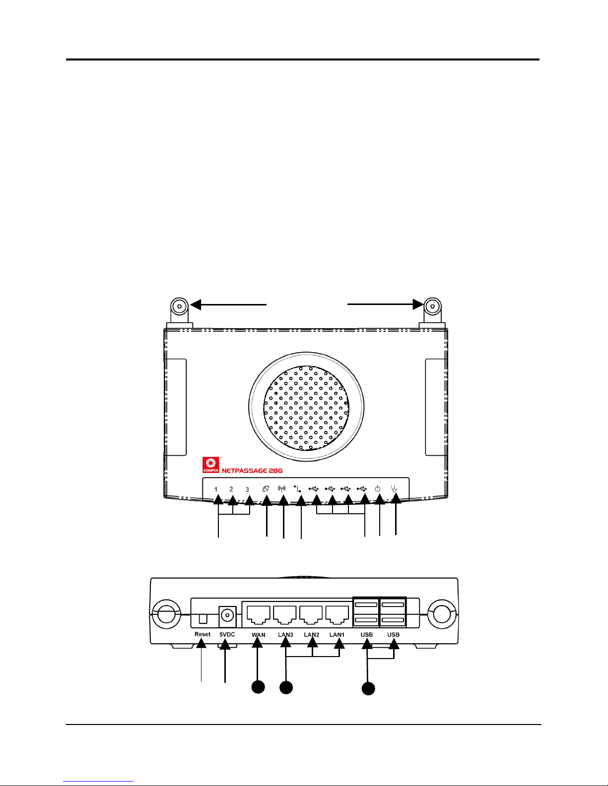
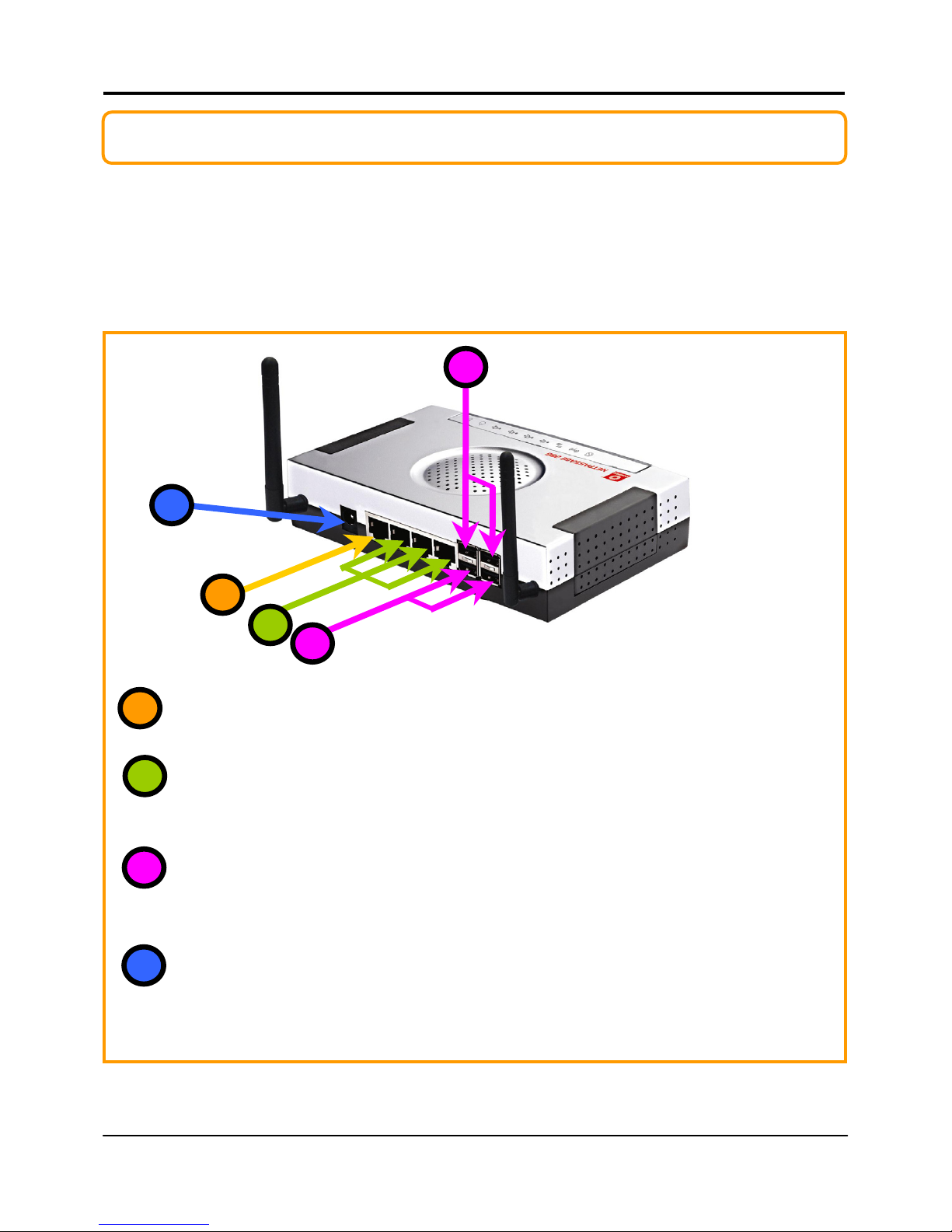
Schematic Overview of the Router
Top View
Back View
#$%&'(()*+,
13
12
11
Page 15

Chapter 2 Getting to Know Your Product
8
Label Name Description
Steady GREEN LAN connection is on.
'
LAN Link/Act LEDs
1, 2,3
Flashing GREEN Data transmission at LAN connection.
#
WAN LED Steady GREEN WAN connection is on
$
Wireless LAN
Link/Act LED
Steady GREEN At least one wireless client is present.
Flashing GREEN Activity is detected in the wireless
network.
)
WAN Link/Act LED Flashing GREEN Data transmission at WAN connection.
&
USB LEDs 1,2,3,4 Steady GREEN USB device is detected.
Flashing GREEN Data transmission at respective USB ports.
%
Power LED Steady BLUE The device has powered up.
*
Diagnostic LED Flashing GREEN It indicates that the firmware is
corrupted.
(
External Antennas SMA detachable antennas
+
Reset Push button To reboot, press once.
To reset password, press and hold the
button for 5 seconds before releasing it.
To restore factory default settings, press
and hold the button for more than 8
seconds before releasing it.
,
5 VDC Power Input
WAN (RJ45 Port) WAN port connects to Cable/ADSL modem
LAN RJ45 Ports
1,2,3
Integrated LAN Switch Ports
USB Ports 1, 2,3,4 Integrated USB2.0 Ports
11
12
13
Page 16
Chapter 3 Let’s Get Going – Hardware Setup
9
Chapter 3: Let’s Get Going-Hardware Setup
Power Up in 4 Steps:
In 4 simple steps, you shall have your router wired and functional. After which, you may
proceed to the software configuration and get yourself ready to surf the Internet at highspeeds!
Connect the Ethernet cable from your Cable/ADSL modem on one end, and
then connect the cable to the socket labeled WAN on the router.
If you have a computer with an Ethernet connection you wish to join to the
wired network, connect an Ethernet cable from that PC to any LAN ports on the
router (labeled 1-3).
Connect the USB devices ( such as USB printer ) to the USB ports of the router.
Next, plug in the power adapter that is supplied to the main electrical supply,
and connect the power plug to the socket on the router.
You may power on the device now. You are done with the hardware setup!
2
4
1
4
2
1
3
3
3
Page 17
Chapter 3 Let’s Get Going – Hardware Setup
10
Network Application Examples
The router is suited to accomplish different network configurations you may have in mind.
Combined with a web-based configuration interface, you can easily set up your featurerich router for these applications.
Here, before proceeding to the next chapter on software setup, you may like to
reference the following three application examples for the router:
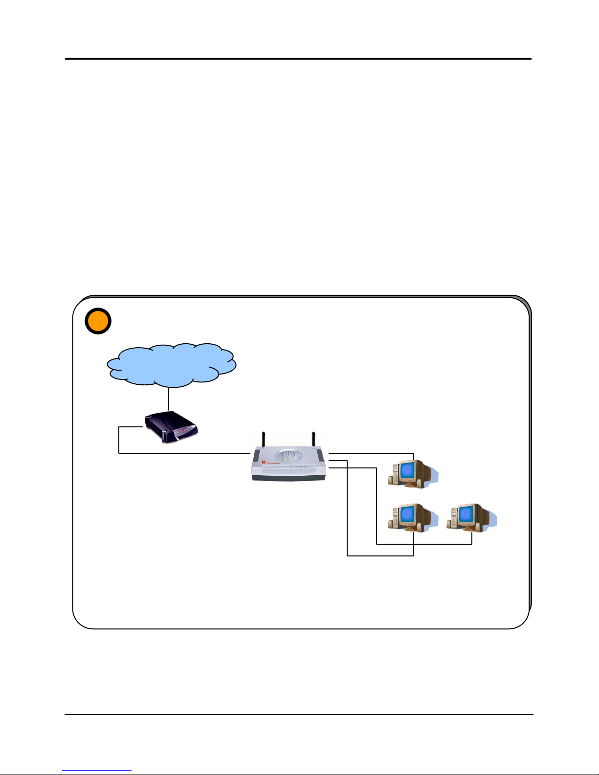
1. Broadband Internet Access Distribution to Fast Ethernet Network
2. Broadband Internet Access Distribution to Fast Ethernet & Wireless Network
Broadband Internet Access
Distribution to a Fast Ethernet Network
1
INTERNET
Router
Connect from Cable/ADSL
modem to WAN port
In this set up example, three computers are connected to the integrated 3-port
10/100Mbps Fast Ethernet switch of the router. These computers are able to share a sin
g
le
broadband Internet connection as well as their resources amongst themselves.
Connect from
computers to the
integrated 3-port
10/100Mbps switch
Page 18
Chapter 3 Let’s Get Going – Hardware Setup
11
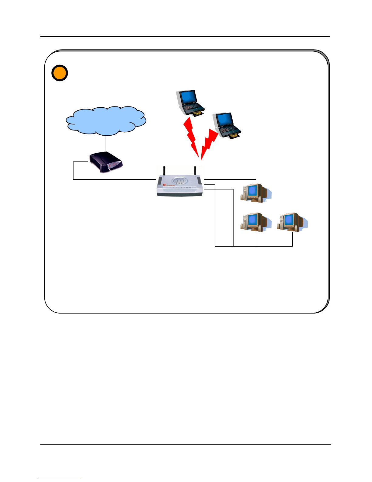
Broadband Internet Access Distribution
To a Fast Ethernet Network & Wireless Network
2
INTERNET
Router
Connect from Cable/ADSL
modem to WAN port
Wireless LAN clients access the
Internet and the wired LAN via the
router
Connect from computers to the
integrated 3-port 10/100Mbps
switch to form LAN
This set up example is similar to the previous with the exception of the two notebooks set up
as wireless clients as illustrated above. They are connected to the Internet as well as the
wired LAN via the 802.11g/801.11b-compatible router. Your wired network can thus be
easily expanded to include wireless clients, enablin
g
them to share network resources and
a broadband Internet access.
Page 19

Chapter 4 Let’s Get Going – Software Setup
12
Chapter 4: Let’s Get Going-Software Setup
Preparing the PCs + Router
The router comes with a powerful array of features that can be administered via a webbased configuration interface. This section of software setup will be presented in two
essential portions aimed to quickly enable effective use of the product:
Part 1. Configuring the PCs - Concerns the Preparation of PCs for network access
Part 2. Basic Router Setup - Covers steps for online access & Internet sharing
Part 1 - Configuring the PCs
The instructions found here will help you configure each of your computers to
communicate with the router.
> For Computers that will be connected to the Fast Ethernet via cables:
The first step is to make sure the PC gets an IP address for which it will use to
communicate with the router and each other across the network. You can begin by
setting up your PC to function as a DHCP client, configuring its network settings to obtain
an IP address automatically. Alternatively, you may want to give your PC a static IP
address if you are an expert user.
Whether you choose to allocate static or dynamic IP settings, the next few pages will walk
you through the performance of this TCP/IP configuration in a step-by-step process. You
may skip to Part 1(a), (b), (c) or (d) according to the Microsoft Windows operating system
you use. Please ensure that you have an Ethernet or wireless adapter (also known as a
network adapter) successfully installed in each PC you are configuring.
Important: By default, Windows 98SE, ME, 2000 and XP
have the TCP/IP protocol installed and set to obtain an
IP address automatically.
If your PC does not have TCP/IP installed, click the Star
t
button and then click on Help. Search for the keyword
TCP/IP and then follow the instructions to install the
protocol.
!
Page 20

Chapter 4 Let’s Get Going – Software Setup
13
Part 1(a) : Configuring your PC to Dynamically obtain an IP address…
If you are using Microsoft Windows 98SE or Windows Millennium
1. Click the Start button. Select Settings
and click the Control Panel icon.
Then double-click the Network icon.
You will see the Network dialog on
the right.
2. On the Configuration tab, highlight
the TCP/IP line corresponding to your
Ethernet adapter and click on the
Properties button. You will be
brought to the TCP/IP Properties
page below.
3. Click on the IP Address tab, and
select Obtain an IP address
automatically.
4. Next, click the Gateway tab, and
verify that the Installed Gateway field
is blank. Now, click the OK button
5. On the Network dialog page, click on
the OK button.
6. Windows may ask you to restart the PC, if so, click the Yes button and allow the PC
to restart. If not, restart the PC to complete the configuration.
!
Windows may ask you for the original Windows
installation disk or additional files. Check for the files at
c:\windows\options\cabs, or insert the Windows
CDROM disc into the CDROM drive and check the
correct file and drive location.
a
Page 21
Chapter 4 Let’s Get Going – Software Setup
14
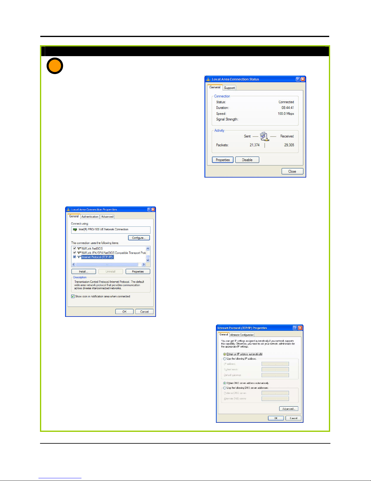
Part 1(b) : Configuring your PC to Dynamically obtain an IP address…
If you are using Microsoft Windows 2000 or Windows XP
1. Click the Start button. Select Settings
and click the Control Panel icon.
Then double-click the Network and
Dial-up Connection (Windows 2000)
or Network Connection (Windows XP)
icon.
2. Double-click the Local Area
Connection icon for the Ethernet
adapter applicable to your Internet
connection, and click the Properties
button. You will be brought to the
dialog page below.
3. On the General tab, make sure the
box next to Internet Protocol (TCP/IP) is
checked. Then highlight Internet
Protocol (TCP/IP), and click the
Properties button.
4. Select Obtain an IP address
automatically.
Then click the OK button on this
page, and the OK button on the
previous page it returns you to.
5. Restart your computer to complete
the PC configuration.
b
Page 22
Chapter 4 Let’s Get Going – Software Setup
15
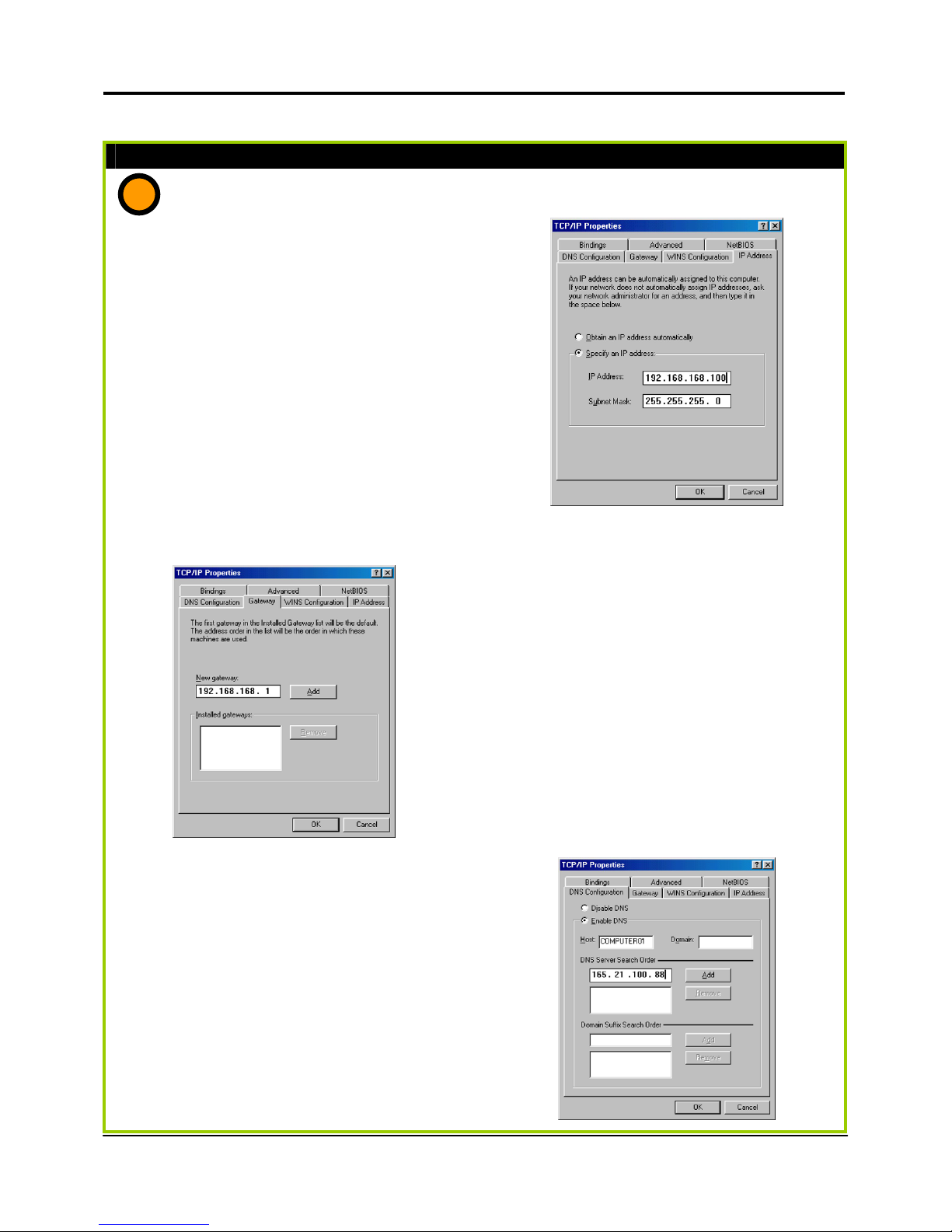
Part 1(c) : Configuring your PC with a Static IP address…
If you are using Microsoft Windows 98SE or Windows Millennium
1. To begin the Static IP address
configuration, follow steps 1 & 2 of
Part 1(a) to get to the page on the
right.
2. Click on the IP Address tab. Then
type in the IP address and Subnet
Mask of 192.168.168.X and
255.255.255.0 respectively, where X is
any number from 2 to 254.
(Note that the default IP address of the
router is 192.168.168.1)
3. Next, click the Gateway tab to see the
dialog page on the left.
4. Under the New Gateway field, key in
the IP address of the router where its
default is 192.168.168.1. Follow up by
clicking the Add button.
5. Now, select the DNS Configuration
tab and on the page you see, select
Enable DNS. Type in a preferred
name as the Host. Then, follow that
up by keying in the IP address of your
DNS Server in the DNS Server Search
Order field and press the Add button.
6. You can complete the set up by
clicking the OK button, and then
restarting the computer.
c
e
X
p
ert
e
X
p
ert
Page 23

Chapter 4 Let’s Get Going – Software Setup
16
Part 1(d) : Configuring your PC with a Static IP address…
If you are using Microsoft Windows 2000 or Windows XP
1. To begin the Static IP address
configuration, follow steps 1, 2 & 3 of
Part 1(b) to get to the page on the
right.
2. Select Use the following IP address,
and then key in 192.168.168.X for the
IP address field, where X is any
number from 2 to 254. Following that,
enter 255.255.255.0 for the Subnet
mask, and key in the IP address of
the router as the Default gateway.
(Note that the default IP address of the
router is 192.168.168.1)
3. Now select Use the following DNS
server addresses, and then key in the
IP address of your DNS server in the
Preferred DNS server field. Finally,
click the OK button to complete.
!
Important: For step 5 above, you should not configure
more than one computer with the same host name
within a network. This will result in a conflict.
The DNS Server’s IP address required in step 5 should be
provided by your Internet Service Provider (ISP). If you
are unsure about it, please contact your ISP.
d
e
X
p
ert
e
X
p
ert
Page 24
Chapter 4 Let’s Get Going – Software Setup
17
For Computers that will be connected as Wireless clients:
The first step is similar to that of wired PCs connected to the Fast Ethernet. We have to
ensure that the wireless client gets an IP address for which it will use to communicate with
the router and each other across the network.
Hence, refer to Part 1(a) and (b) for the setup instructions, while noting that the likely
network connection name you will encounter in Windows XP is Wireless Network
Connection corresponding to the wireless Ethernet adapter you use.
Once you have completed the IP configuration for the wireless client, you may proceed
to set up your wireless client’s SSID (Network name) so that it will connect with the router.
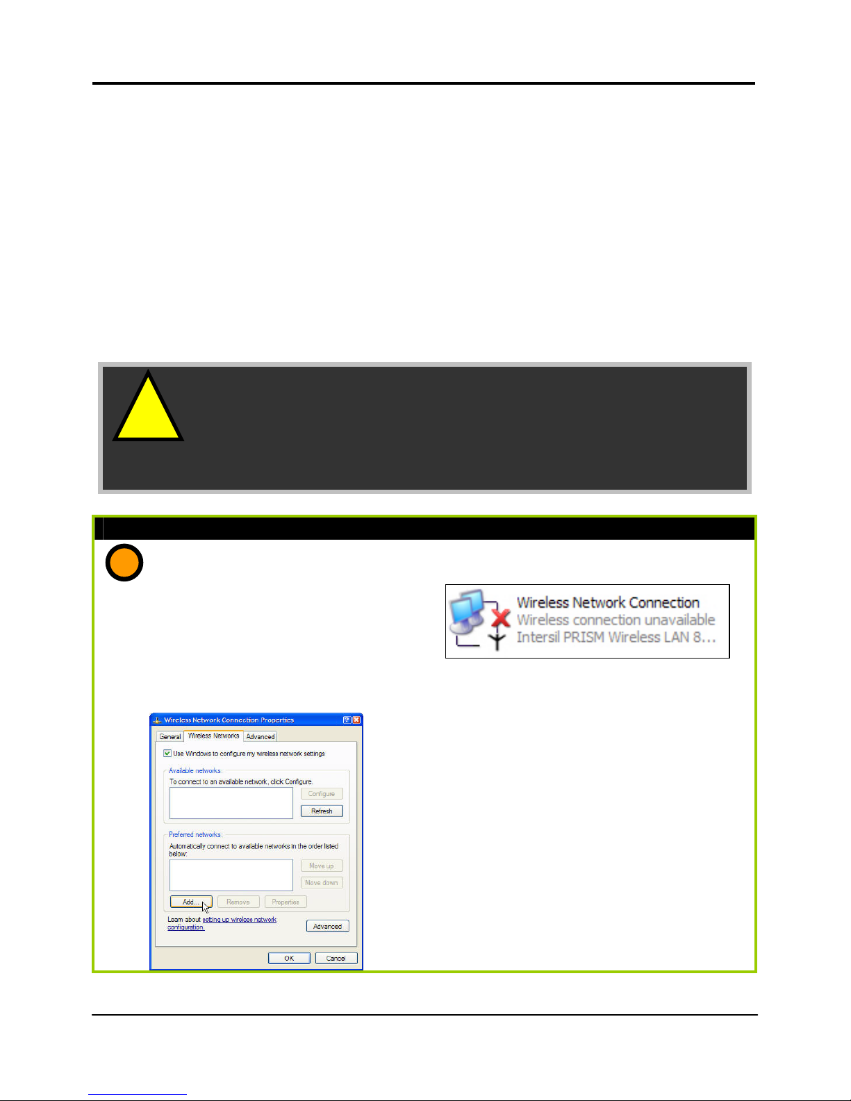
Part 1(e) : Configuring your Wireless Client…
If you are using Microsoft Windows XP
1. Right-click on Wireless Network
Connection corresponding to the
wireless Ethernet adapter you wish to
connect with the router, and click on
Properties.
2. On the dialog box presented, click the
Wireless Networks tab, and click on the
Add button.
e
!
Important: Windows 98SE/ME/2000 users, the following
configuration steps for wireless client setup may differ fo
r
different wireless Ethernet adapters with vendor specific
driver utilities. Please refer to your adapter’s manual fo
r
more information.
Page 25
Chapter 4 Let’s Get Going – Software Setup
18
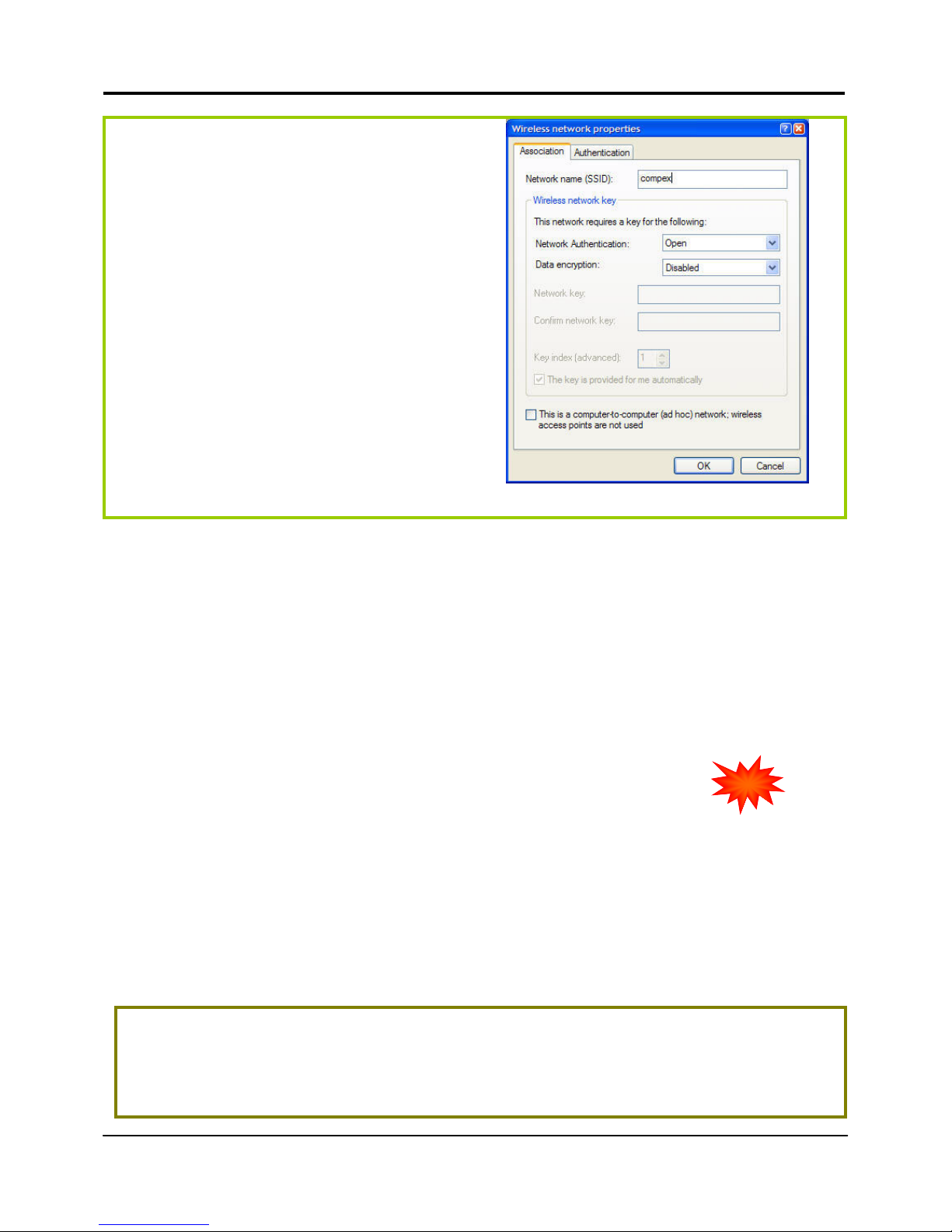
3. Next, key in a Network name with the
SSID of the wireless network. It must be
the same as the WLAN name (ESSID)
in Part 2. For illustration purpose, we
typed compex. (Take note that SSID is
case- sensitive).
Ensure that the Network name (SSID)
value is the same for all the wireless
clients in the same wireless network.
For now, you may leave the other
information as default (Network
Authentication -> Open ; Data
encryption -> Disabled).
Completing Part 1, we have set up our PCs & wireless clients’ IP addressing properties. We
will now be ready to discuss the software setup of the router configurations to go online!
Part 2 - Basic Setup
In this portion on the basic set up, you will find information on how you may configure the
NetPassage 28G to function in your network, to access the Internet and begin sharing the
connection with your wired and wireless clients. Please note that the NetPassage 28G, by
factory default, is loaded with router firmware.
uConfig: Bringing You to the Web-Based Configuration Without Fail
Compex has developed a powerful uConfig utility which will provide you hassle-free
access to the router’s web-based configuration page. Whether you have non-standard
TCP/IP settings on the PC, or you have changed but forgotten the router’s default
management IP, uConfig will bring you to the router’s set up – every time!
It is simple. Ensure that the router is switched on, and the PC is connected to a LAN port,
then you will be brought to the web-based configuration page by following the 3 simple
steps below.
Part 2 : Getting Ready to go Online!
Accessing the Web Page Interface through uConfig
1. Insert the Product CD into your CD-ROM drive. The CD will run automatically. From
the UUttiilliittiieess section, select to install the uuCCoonnffiigg utility to your hard disk.
exclusive!
Page 26
Chapter 4 Let’s Get Going – Software Setup
19
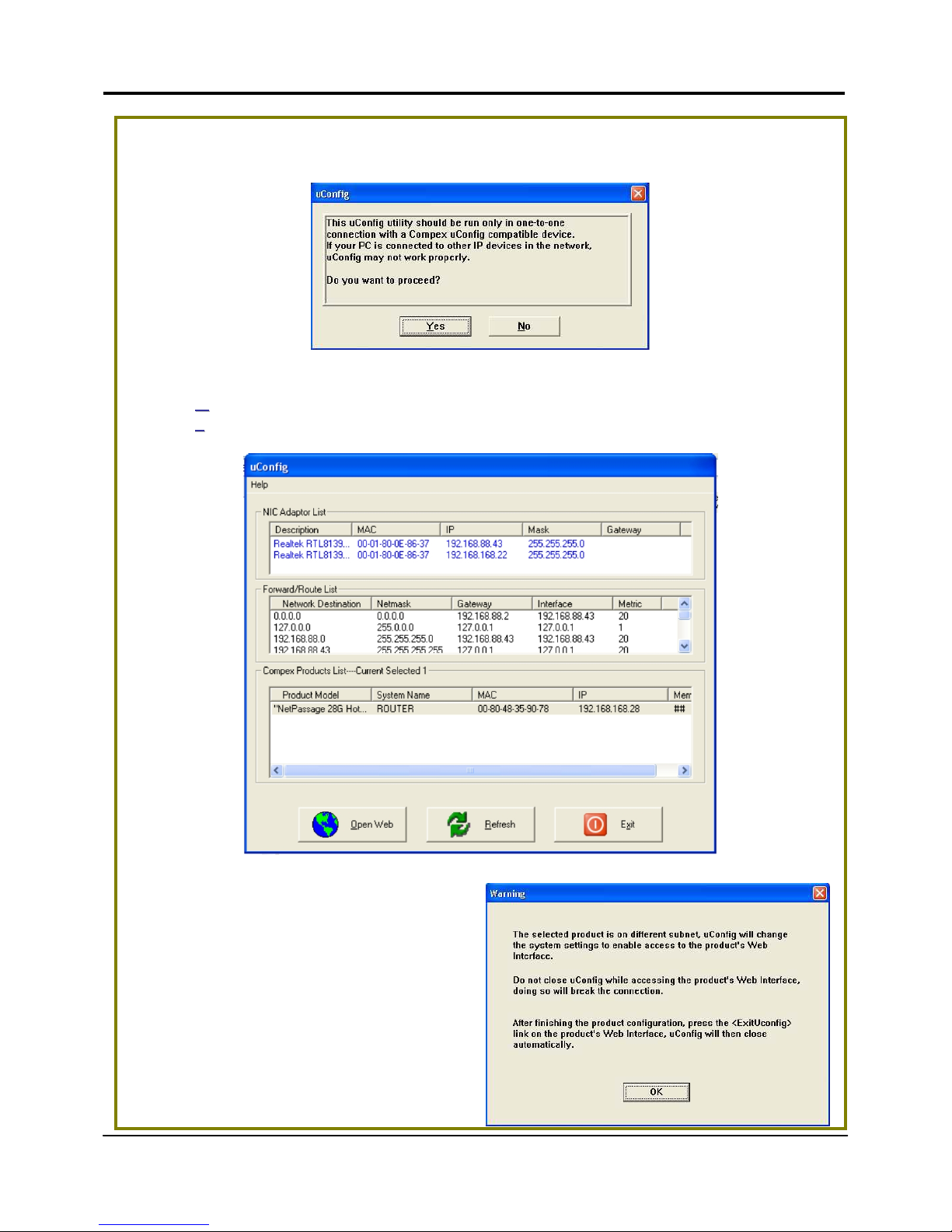
2. When the utility has been installed, double-click on the
uuCCoonnffiig
g icon. The following
screen will appear, click on the YYeess button to proceed.
3. Select NNeettPPaassssaaggee 2288GG HHoottssppoott in the CCoommppeexx PPrroodduuccttss LLiisstt section and click on
the OO
ppeenn WWeeb
b button. To retrieve and display the latest device(s) in the list, click on
the RR
eeffrreessh
h button.
4. Do not exit the uConfig program
while accessing to the web-based
interface. This will disconnect you
from the device. Click on the OOKK
button to proceed.
Page 27
Chapter 4 Let’s Get Going – Software Setup
20
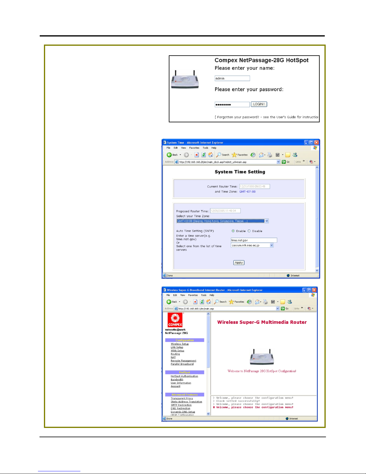
5. At the login page, press the
LLOOGGIINN!
! button to enter the
configuration page. The default
password is “password”.
6. For the first time login, you will
be prompted to select your
time zone setting first before
accessing the router’s main
web page. Take note that
during the next and
subsequent logins, you will
not see the System Time
Setting page again.
7. You will then reach the home
page of your access point’s
web-based interface.
Page 28
Chapter 4 Let’s Get Going – Software Setup
21
Part 3 (a) : Getting Ready to go Online!
Completing your general LAN Setup
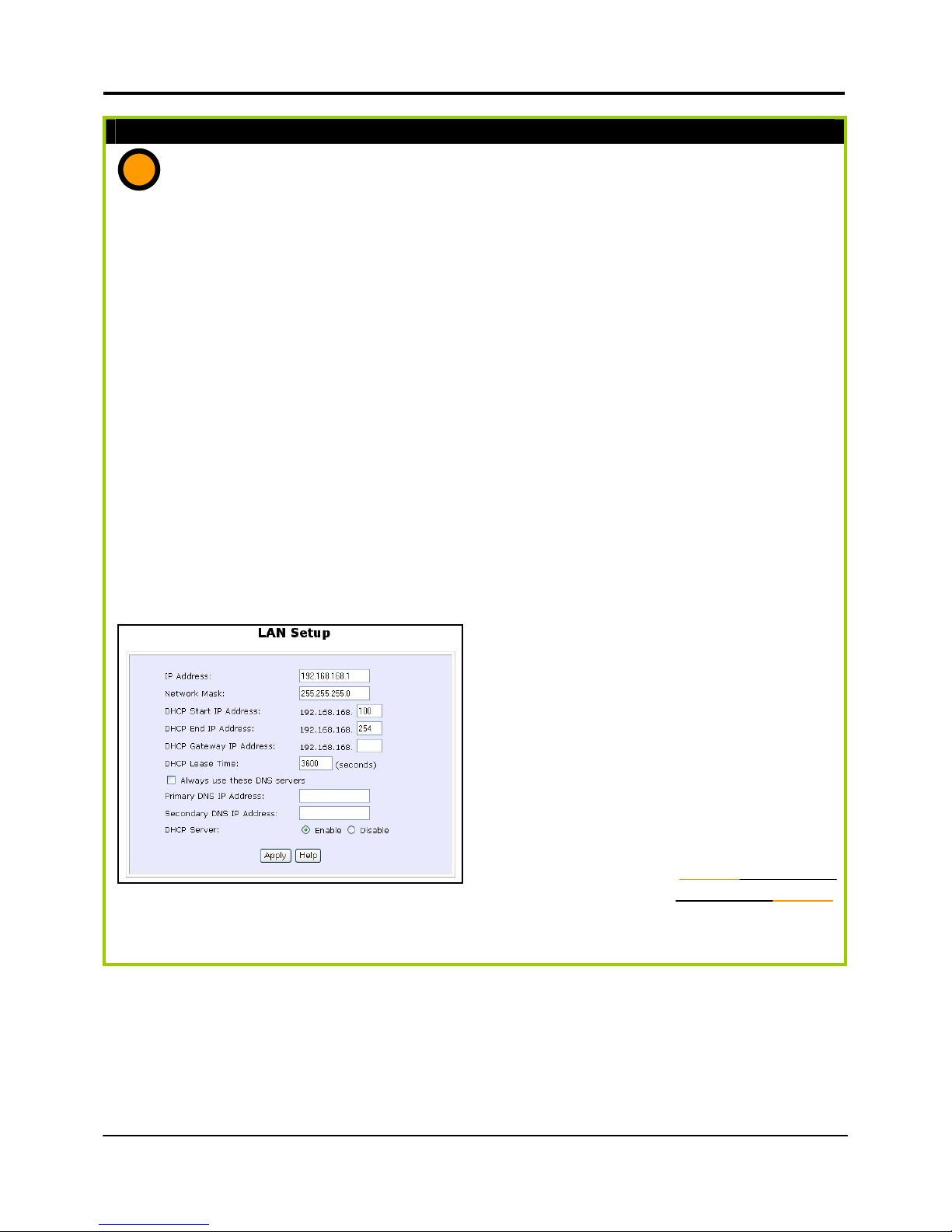
1. The DHCP Start IP Address and the DHCP End IP Address has been pre-
configured from 192.168.168.100 to 192.168.168.254 (You may select any number
from 2 to 254).
2. Next, we shall move on to
configure the router to handle IP
addressing. Click on LAN Setup
under CONFIGURATION.
You will note that 192.168.168.1 is the
default IP address assigned to the
router, with a Network Mask of
255.255.255.0. You may leave them as
they are. (The router’s subnet is
192.168.168.0)
3. For DHCP Gateway IP address,
set it as 192.168.168.1 unless
you have another device you
like to use as the router for
your clients.
4. Leave the Always use these
DNS servers unchecked, unless
you wish to access certain
specific DNS servers only. You
may leave the Primary DNS IP
Address and Secondary DNS
IP Address as blank. If the
Always use these DNS servers
is set to be enabled, the user
has to input the Primary DNS IP
Address.
5. Please remember to click
Reboot Router under SYSTEM
TOOLS and hit the Reboot
button to let the settings take
effect.
a
Technology Primer
Learn more from our DHCP
Page 29

Chapter 4 Let’s Get Going – Software Setup
22
The following table lists out the parameters relevant to your LAN setup. You can replace
the default settings with appropriate values to suit the needs of your LAN.
LAN Parameters Description
IP Address The IP address of your router is set by default to 192.168.168.1.
When the DHCP server of the router is enabled, unless you set a
different <DHCP Gateway IP address>, this LAN <IP address>
would be allocated as the Default Gateway of the DHCP client.
Network Mask The Network Mask serves to identify the subnet in which your
router resides. The default network mask is 255.255.255.0.
The next two fields (DHCP Start IP Address and DHCP End IP Address) allow you to define
the range of IP addresses from which the DHCP Server can assign an IP address to the
LAN.
DHCP Start IP
Address
This is the first IP address that the DHCP server will assign. The
value that you input here should belong to the same subnet as
your router. For example, if the IP address and network mask of
your router are 192.168.168.1 and 255.255.255.0 respectively, the
DHCP Start IP Address should be 192.168.168.X, where X can take
any value from 2 to 254. It is pre-set to 192.168.168.100.
DHCP End IP
Address
This is the last IP address that the DHCP server can assign. It
should also belong to the same subnet as your router. For
instance, if the IP address and network mask of your router are
192.168.168.1 and 255.255.255.0 respectively, the DHCP End IP
Address should be 192.168.168.X, where X can take any value
from 2 to 254. It is pre-set as 192.168.168.254.
DHCP Gateway IP
Address
Insert the IP address of the gateway to Internet or of the router if
this router is the one connecting to the Internet.
If your network uses multiple gateways/routers, you may wish the
router to act as DHCP server to a LAN segment while another
router/AP connects to the Internet or to another LAN.
Though usually, the DHCP server also acts as the Default
Gateway of the DHCP client, the router gives you the option to
define a different <DHCP Gateway IP address>, which will be
allocated as the Default Gateway of the DHCP client.
The DHCP client will thus receive its dynamic IP address from the
router but will access to the Internet or to the other LAN through
the Default Gateway defined by the <DHCP Gateway IP
address>.
Always use these
DNS servers
Enable this checkbox if you want the router to only use the DNS
server you have specified below.
Page 30

Chapter 4 Let’s Get Going – Software Setup
23
Primary DNS IP
Address
The IP address of the DNS server is usually provided by your ISP.
Secondary DNS IP
Address
This optional field is reserved for the IP address of a secondary
DNS server.
DHCP Server If you disable the DHCP server, you will need to manually
configure the TCP/IP parameters of each computer in your LAN.
Page 31

Chapter 4 Let’s Get Going – Software Setup
24
You can now proceed to Part 3(b) which pertains to the set up of the router’s wireless
feature.
Part 3(b) : Getting Ready to go Online!
Completing your Wireless Setup
1. Quickly we move on to the
router settings for your wireless
users. Click on Wireless Setup
under CONFIGURATION and
you will see the settings screen.
2. It is important here you key in
the WLAN name (ESSID) to be
that which you intend to use
for your wireless clients. This is
the same as the Network
Name (SSID) discussed in Part
1(e).
Remember to change your
wireless clients’ settings after
the router has rebooted and
the new SSID has taken effect.
3. Now choose a Wireless mode
suitable for the types of
devices you have in your
network. Modes such as pure
802.11g or mixed network, etc,
are supported, and you may
also define your preferred
Operating frequency.
4. Leave Security mode as None for now and
the other remaining settings empty. Click the
Apply button to complete your wireless setup.
Take note that Security Mode will be
discussed in the next chapter.
5. Please remember to click Reboot Router
under SYSTEM TOOLS and hit the Reboot
button to let the settings take effect.
b
Page 32

Chapter 4 Let’s Get Going – Software Setup
25
CONFIGURATION: WAN SETUP
The WAN Setup in Part 3(c) is a critical section on broadband setup. A successful
configuration requires you to identify the type of broadband Internet access you
subscribed to:
i. Cable Internet where your ISP dynamically assigns an IP address to you, refer to
Part 3(c)i titled WAN Setup - Cable Internet with Dynamic IP Assignment.
ii. Cable Internet where your ISP provides you with an IP (or a range of IP
addresses), refer to Part 3(c)ii titled WAN Setup - Cable Internet with Static IP
Assignment.
iii. ADSL Internet that requires standard PPP over Ethernet (PPPoE) for authentication,
refer to Part 3(c)iii titled WAN Setup - ADSL Internet using PPP over Ethernet
(PPPoE).
iv. ADSL Internet that requires standard Point to Point Tunneling Protocol (PPTP) for
authentication, refer to Part 3(c)iv titled WAN Setup – ADSL Internet using Point
to Point Tunneling Protocol (PPTP).
Part 3(c)i : WAN Setup - Cable Internet with Dynamic IP Assignment
Selecting the Correct WAN Type
The router is pre-configured to support a WAN type that dynamically obtains an IP address
from the ISP. However, you may verify that the settings are correct with the following steps:
1. Under the CONFIGURATION on the
command menu, click on WAN
Setup.
2. On the WAN Dynamic Setup
screen that follows, verify that the
WAN Type reads Dynamic (DHCP)
in red colour. Otherwise, click on
the Change button.
3. Simply select Dynamic IP Address,
hit the Apply button and you are
done!
c
Page 33

Chapter 4 Let’s Get Going – Software Setup
26
4. Please remember to click Reboot
Router under SYSTEM TOOLS and
hit the Reboot button to let the
settings take effect.
Note: There are exceptional cases where additional configuration is required before
an IP address will be allocated by your ISP to the router.
a. Certain ISPs log the MAC address of the first device connected to the
broadband channel and refuse to release an IP address unless the MAC
address matches the one in their log. Therefore, if yours is not a new Cable
Internet subscription (i.e. you have an adapter formerly connected directly
to your cable modem), refer to steps 5 - 7 to clone the “approved” MAC
address to the router.
b. Certain ISPs require the authentication of a DHCP Client ID before releasing
an IP address to you. The router uses the System Name set in the System
Identity as the DHCP Client ID.
Therefore, if this is the case, refer to your ISP for the correct DHCP Client ID to
be set and follow steps 8 - 10 to accomplish the set up.
5. Steps 5 - 7 are for those who need
to clone their Ethernet adapter’s
MAC address.
In the WAN Setup found under the
CONFIGURATION command menu,
you will see the Advanced WAN
Options. Click MAC Address
Cloning to continue.
!
Important: Please note the exceptional cases described
on the following page for certain Cable Internet Service
Providers.
Page 34

Chapter 4 Let’s Get Going – Software Setup
27
6. Simply click on the Clone button so
that your router clones the ISPrecognized MAC address of your
Ethernet adapter.
7. Please remember to click Reboot
Router under SYSTEM TOOLS and
hit the Reboot button to let the
settings take effect.
Take note: (If ever required, you may reset
the router’s MAC address to its factory
default by clicking Reset on that same page)
8. Steps 8 - 10 are for those who need
to set up the System Name in System
Identity so that your ISP can
authenticate it as a valid DHCP
Client ID.
Click on System Identity under the
SYSTEM TOOLS command menu.
9. On the following screen, key in the
your ISP assigned DHCP Client ID as
the System Name (You may also like
to key in a preferred Systems Contact
person and the System Location of the
router). Click the Apply button to
complete.
10. Please remember to click Reboot
Router under SYSTEM TOOLS and hit
the Reboot button to let the settings
take effect.
Page 35

Chapter 4 Let’s Get Going – Software Setup
28
Part 3(c)ii : WAN Setup - Cable Internet with Static IP Assignment
Selecting the Correct WAN Type
If you have an ISP that leases a static IP for your subscription, you will need to configure your
router’s WAN type accordingly. For example, if the ISP provided you with the following set
up information, you can set up your WAN as described below:
IP Address : 203.120.12.47
Network Mask : 255.255.255.0
Gateway IP Address : 203.120.12.15
1. Under the CONFIGURATION on the command menu, click on WAN Setup.
2. Access the Select WAN Type page
and choose Static IP Address before
clicking the Apply button. You will
then be brought to the following
page requiring your inputs.
3. Fill in the information provided by your
ISP in the IP Address, Network Mask and
Gateway IP Address fields, followed by
clicking the Apply button.
4. Please remember to click Reboot Router
under SYSTEM TOOLS and hit the Reboot
button to let the settings take effect.
c
Page 36

Chapter 4 Let’s Get Going – Software Setup
29
Part 3(c)iii : WAN Setup - ADSL Internet using PPP over Ethernet (PPPoE)
Selecting the Correct WAN Type
If you subscribe to an ADSL service using PPP over Ethernet (PPPoE) authentication, you can
set up your router’s WAN type in these steps that follow. For example, you may configure an
account whose username is ‘guest’ as described below:
1. Under the CONFIGURATION on the
command menu, click on WAN Setup.
2. Access the Select WAN Type page and
choose PPP over Ethernet before clicking
the Apply button. You will then be
brought to the following page requiring
your inputs.
3. For Username, key in your ISP
assigned account name (e.g. guest
for this example), followed by your
account Password.
4. Select Always-On if you wish that
your router will always maintain an
established connection with the ISP.
Otherwise, you may select On-
Demand. The router will connect to
the ISP automatically when it receives
Internet requests from your PCs.
The Idle Timeout setting is associated with the On-Demand option, allowing you to specify
the value (in seconds) for which the router will disconnect from the ISP after the last Internet
activity. A value of “0” will disable idle timeout. Reconnect Time Factor is associated with the
Always-on and specifies the maximum time the router will wait before re-attempting to
connect with your ISP. Hit the Apply button and Reboot the router.
c
Page 37

Chapter 4 Let’s Get Going – Software Setup
30
Part 3(c)iv : WAN Setup – ADSL Internet using PPTP
Selecting the Correct WAN Type
If you subscribe to an ADSL service using Point to Point Tunneling Protocol (PPTP)
authentication, you can set up your router’s WAN type in these steps that follow. For
example, if the ISP provided you with the following set up information, you can set up your
WAN as described below:
IP Address : 203.120.12.47
Network Mask : 255.255.255.0
VPN Server : 203.120.12.15
1. Under the CONFIGURATION on the command menu, click on WAN Setup.
2. Access the Select WAN Type
page and choose PPTP before
clicking the Apply button. You
will then be brought to the
following page requiring your
inputs.
3. Fill in the information provided by
your ISP in the IP Address,
Network Mask and VPN Server
fields, followed by clicking the
Apply button.
4. Please remember to click Reboot
Router under SYSTEM TOOLS and
hit the Reboot button to let the
settings take effect.
The Idle Timeout setting is associated with the On-Demand option, allowing you to specify
the value (in seconds) for which the router will disconnect from the ISP after the last
Internet activity. A value of “0” will disable idle timeout.
c
Page 38

Chapter 5 Advanced Configuration
31
Chapter 5: Advanced Configuration
Detailed Configuration of the Router
This part of the setup for the router is meant for the advanced user who requires more
than the essential information to set up a wired/wireless network infrastructure. Adopting
a top-down approach to explain the features found on the router, what follows is a
detailed walkthrough of the configurable settings available within the web-based
administration menus:
CONFIGURATION : Wireless Setup
The router supports wireless LAN
connectivity that is fully-compliant
with the IEEE 802.11g and IEEE
802.11b standards. It also employs
a WPA-PSK or WEP to secure
data transmissions within your
wireless clients and the network.
Operation Mode : The router can choose to operate as an access point or a
access point client. The Access Point operation mode is set
by default. If you want to change the operation mode, just
click on the Change button.
ESSID
Enter a preferred name for the wireless network. Your
wireless clients must be configured with the same ESSID (or
sometimes simply referred to as SSID).
Wireless mode
: Select from a list of wireless modes available:
- 802.11b only
This mode supports wireless B clients with bandwidth up to
11Mbps in the distance range of 2.4Hz.
- 802.11g only
e
X
p
ert
e
X
p
ert
Page 39

Chapter 5 Advanced Configuration
32
This mode supports wireless G clients that offer transmission
over relatively short distances at up to 54Mbps.
- 802.11b/g mixed
This mode supports both wireless B and G clients. The basic
rates are 1Mbps, 2 Mbps, 5.5 Mbps, 11Mbps, 6 Mbps, 12
Mbps and 24 Mbps.
- Super-G
This mode supports wireless super-G clients that offer
transmission rates of up to 108Mbps in the 2.4GHz frequency
band.
Operating frequency : This option allows you to select a frequency channel for the
wireless communication.
Transmit Power : This option allows you to select a specific transmit power for
the wireless communication. The Transmit Power controls
the signal strength transmitted by the antenna. If the
antenna has a weak RF coverage, increase the Transmit
Power. If the antenna has a strong RF coverage, decrease
the Transmit Power.
Security mode : The router supports three types of authentication : WPA-PSK
and WEP. Two types of WEP private encryption are 64-bit
WEP and 128-bit WEP. You may also opt to disable wireless
security by setting Security mode to Disable. (Not
recommended).
Close system : The router will not broadcast its WLAN name (ESSID) when
Close system is enabled. By default, Close system is
disabled.
Page 40

Chapter 5 Advanced Configuration
33
Hardware setup of the Router
The router can also operate in two modes such as Access Point and Access Point Client.
With its built-in USB ports functionality that is easy to operate, you can print from any PC
on the network to any printer connected to the router via its USB port.
The above illustration is an example on how to use the two routers as Access Point Mode
and Access Point Client respectively to print wirelessly in two separate rooms.
1. Connect an Ethernet cable to your Cable/ADSL modem and then to the socket
labeled WAN on your router.
2. Connect one end of the RJ45 Ethernet cable to your network adaptor in your PC
and the other end to the LAN port of your router.
Router as Access
Point Mode
INTERNET
PC 1
ADSL
Modem
Study Room
Infant Room
Server 1
Router
as Access Point Client
Server 2
PC 2
Printer
Page 41

Chapter 5 Advanced Configuration
34
3. Next, plug in the power adapter that is supplied in the package to the main
electrical supply, and connect the power plug to the socket on the router. You may
power on the device now. You are done with the hardware setup!
Configuring your PC
Configure your PC to obtain its IP address automatically. Alternatively, you may want to
give your PC a static IP address if you are an expert user. For the details in configuring
your PC to obtain dynamic IP address, kindly refer to the User’s Manual on.
Configuration for the Router as Access Point
1. When all hardware installation and PC configuration have done, insert the Product
CD to your CD-ROM drive, go to Utilities section and activate the uConfig program,
select Router and click on OpenWeb button.
2. The default password is pre-entered in the field provided. Therefore, simply click on
LOGIN! button to access to the main page of the router.
3. From your Configuration Command menu, select Wireless Setup. You may leave the
ESSID as the default setting.
4. Next, you can select the channel at Channel 10, 2.4570GHz, for your operating
frequency unless you have problem operating at this frequency.
5. Click on Apply button to update the changes.
Page 42

Chapter 5 Advanced Configuration
35
6. Next, proceed to the WAN Setup from the Configuration Command menu. From
here, choose the correct WAN type depending on your ISP. For example, if you are
using the cable modem, use Dynamic WAN type. (For more details, refer to the
section on WAN Setup).
7. Reboot the router.
Page 43

Chapter 5 Advanced Configuration
36
Configuration for the Router as Access Point Client
1. As shown in this screen, when the operation mode is defaulted to Access Point, click
Change to edit the operation mode. Select Access Point Client.
2. Update the required changes.
3. Click on Apply button to update the changes.
4. Next, proceed to the WAN Setup from the Configuration Command menu. Set your
WAN Type to PPPoP Setup and click Apply to make the changes. Ensure that your
modem is connected to your router’s WAN port.
5. Enter the Username and password that are provided by your ISP. Click Apply to
update the changes. When done, logout from your router’s main page.
Page 44

Chapter 5 Advanced Configuration
37
CONFIGURATION: Wireless Setup: Security Mode
Security plays a vital role of securing wireless (802.11) networks to prevent unauthorised
users from accessing sensitive data in the networks. WPA is one of the strongest standards
for wireless security.
Having learnt the significance of implementing a security-based network infrastructure,
listed here are the steps to configure your router: (Take note that the router is operating
as an access point. We use it as an example here).
The Security mode comes in two types: WPA-PSK and WEP.
WPA-Pre Shared Key (WPA-PSK) is a special mode for home users without authentication
server.
To set the Security mode to WPA-PSK, follow these instructions:
1. Under the CONFIGURATION
command menu, you will find the
Wireless Setup page. Click on the
Change button next to the Security
mode. Then check the radio button
next to WPA-PSK, followed by the
Apply button.
2. You will see the page of the Wireless
Setup enabled with WPA-PSK.
3. Enter the inputs, then followed by the
Apply button. You must enter at least
8 ASCII characters. Enter the inputs,
then followed by the Apply button.
Page 45

Chapter 5 Advanced Configuration
38
Wired Equivalent Privacy is implemented in the network. It is a security protocol in a
wireless local area network.
To set the Security mode to WEP, follow these instructions:
1. Under the CONFIGURATION
command menu, you will find the
Wireless Setup page. Click on the
Change button next to the Security
mode. Then check the radio button
next to WEP, followed by the Apply
button.
2. You will see the page of the
Wireless Setup enabled with WEP,
displaying the following
parameters:
Transmission key:
This option allows you to select from
a list of user-defined encryption
keys (1-4).
Key 1-4:
You may enter up to 4 encryption
keys. If you selected 64-bit WEP,
you will need to enter 10
characters. For 128-bit WEP, it
requires 26 characters.
( See the table below).
The table below describes the 64-bit and 128-bit encryption.
3. Enter the inputs, then followed by the Apply button.
WEP encryption Hexadecimal ASCII
64-bit 10 characters 5 characters
128-bit 26 characters 13 characters
Page 46

Chapter 5 Advanced Configuration
39
To set the Security mode to Disabled, follow these instructions:
1. Under the CONFIGURATION
command menu, you will find the
Wireless Setup page. Click on the
Change button next to the Security
mode. Then check the radio button
next to Disabled, followed by the
Apply button.
2. You will see the page of the Wireless
Setup set to Disable.
3. Click the Apply button.
Page 47

Chapter 5 Advanced Configuration
40
CONFIGURATION : Wireless Setup: Wireless Pseudo VLAN
The Wireless Pseudo VLAN feature on the router is exclusively created to solve the
problem of privacy and data protection, to provide multiple levels of inter-client security.
It is a natural extension of the Ethernet-based VLAN onto the wireless network in a
corporation or even in a public ‘hotspot’ establishment.
Wireless Pseudo VLAN segregates a single wireless LAN into multiple virtual LANs.
Communication is only possible between wireless nodes of the same VLAN, and the
router allows you to create a virtual LAN containing either a single wireless user, or a
group of users. We call this Per Node and Per Group Wireless Pseudo VLAN respectively.
Per Node Wireless Pseudo VLAN
Per Node Wireless Pseudo VLAN, if implemented, segregates every wireless user, or node,
in its own Pseudo VLAN. As illustrated in the figure below, while access to the Internet is
unrestricted, wireless clients may not communicate with one another. This
implementation of Wireless Pseudo VLAN is most suitable for public premises such as Wi-Fi
‘hotspots’ at coffee joints or the airport. Users who log onto such wireless networks can be
certain that their files will not be subjected to prying eyes.
INTERNET
Per Node Wireless Pseudo VLAN
Cable/ADSL
modem
Pseudo VLAN
Node
1
Pseudo VLAN
Node
2
Pseudo VLAN
Node
3
Router
Page 48

Chapter 5 Advanced Configuration
41
Steps to set up Per Node Wireless Pseudo VLAN on the router
Setting up Per Node Wireless Pseudo VLAN on the router is merely a 3 steps affair:
1. Under the CONFIGURATION command
menu, you will find the Advanced
Wireless Options within the Wireless
Setup page. Click on the Wireless
Pseudo VLAN button.
2. By default, you will note that
Wireless Pseudo VLAN is disabled.
Click the Change button.
3. On the next screen, click the Per
node radio button and hit Apply to
complete the selection.
With this, you have successfully set up
a Per Node Wireless Pseudo VLAN
whereby each wireless user is isolated
from one another.
Page 49

Chapter 5 Advanced Configuration
42
Per Group Wireless Pseudo VLAN
In contrast to single user segregation, Per Group Wireless Pseudo VLAN supports multiple
wireless nodes per VLAN. Users grouped in the same Wireless Pseudo VLAN may access
files from each other, but users from different groups are prevented from this
communication. The router supports four Pseudo VLAN groups.
This implementation of Wireless Pseudo VLAN is useful for corporate workgroups or
departmental wireless clients’ setup.
Steps to set up Per Group Wireless Pseudo VLAN on the router
Per Group Wireless Pseudo VLAN gives you great flexibility in your wireless network set up,
and with 6 steps, you may configure private virtual LANs quickly and easily between
workgroups:
1. Under the CONFIGURATION command
menu, you will find the Advanced
Wireless Options within the Wireless
Setup page. Click on the Wireless
Pseudo VLAN button.
INTERNET
Per Group Wireless Pseudo VLAN
Cable/ADSL
modem
Pseudo VLAN
Group
1
Pseudo VLAN
Group
2
Pseudo VLAN
Group
3
Internet &
Fast Ethernet
Router
Page 50

Chapter 5 Advanced Configuration
43
2. By default, you will note that Wireless
Pseudo VLAN is disabled. Click the
Change button.
3. On the next screen, click the Per group
radio button and hit Apply to
complete the selection of your Pseudo
VLAN Type.
4. You will be brought to the following
set up screen requiring you to assign
the hardware address of your client
to a specific group you wish to
segregate.
Click on the Add button.
5. From the Add Group drop-down list,
choose a group number and then key
in the Hardware Address (hardware
MAC address) of the client before
clicking the Add button.
6. Until now, you may continue to add
more groups or assign more wireless
clients to groups with steps 1 to 5
described here.
In the example shown on the right, 3
wireless clients are divided into two
Per Group Wireless Pseudo VLANs 01
and 02. Two clients are assigned to
Group 01 while the other one is put
into Group 02.
Page 51

Chapter 5 Advanced Configuration
44
CONFIGURATION : LAN Setup : Advanced DHCP Server Options
For instructions on basic LAN setup within the router, please refer to Chapter 4, part 2. In
this portion, we shall examine the Advanced DHCP Server Options available to the
network administrator.
You can easily manage your network’s IP address allocation with the built-in DHCP server
found on the router. Once set up as described in Chapter 4, it will automatically and
dynamically allocate addresses from a pool, to devices or computers connected to the
network. To learn more about DHCP, please turn to the DHCP Technology Primer found
on the Product CD.
Under the Advanced DHCP Server Options, we will discuss making DHCP Server
reservations for specific IP and MAC addresses. As illustrated below, this feature is useful in
situations when you have to set up a publicly accessible FTP/HTTP server that resides within
a private LAN. It will require a fixed IP address, but at the same time, your private LAN
comprises a group of PCs whose IP address allocations you want the DHCP Server to
manage dynamically.
Hence, with the ability to make IP reservations, you can assign a fixed IP to your FTP/HTTP
server and then inform the DHCP Server not to assign this IP in its dynamic allocation.
Technology Primer
Learn more from our DHCP
INTERNET
Cable/ADSL
Modem
Router with built-
in DHCP server
Wireless Clients
(Dynamic IP
Addressing)
Public
FTP/HTTP Server
with fixed IP (IP
address reserved in
DHCP server)
Workstations
(Dy
namic IP addressin
g)
Fixed & Dynamic IP addressing: DHCP Server Reservations
Page 52

Chapter 5 Advanced Configuration
45
Steps to configure Advanced DHCP Server Options in the router
Listed here are the steps to configure the Advanced DHCP Server options available on
the router:
1. Under the CONFIGURATION
command menu, you will find the
Advanced DHCP Server Options
within the LAN Setup page.
2. You may click on Show Active DHCP
Leases to view information of the
current IP leases managed by the
DHCP server. Otherwise, you can
click on DHCP Server Reservations to
reserve any specific IP Address for a
certain network MAC address.
3. To add DHCP Server Reservations,
click on the Add button.
4. On the following screen, enter the IP
Address you wish to reserve and the
Hardware Address (MAC address) of
that PC’s Ethernet card. Finish up by
clicking on the Add button.
5. You will see the entered IP address
and Hardware Address tabled as on
the right. After this, you may also
add more reservations.
Page 53

Chapter 5 Advanced Configuration
46
CONFIGURATION : WAN Setup
For information pertaining to WAN setup on the Router, you should refer to Part 2(d) in
Chapter 4. If you have a broadband service that requires additional configuration,
please contact your ISP for further help.
CONFIGURATION : Routing
The router allows the network administrator to add a static routing entry into the routing
table. Other than the default Router to the Internet, the router may reroute the IP packets
to another network you defined. This feature is very useful for a network with more than
one router.
The diagram below illustrates a case which you have two routers in the network. One
router is used for broadband Internet sharing and another router connects to a remote
office. You may then define a static routing entry in the router to re-route the packets to
the remote office.
!
Important: You do NOT need to set any routing
information if you are simply configuring the router fo
r
broadband Internet sharing. Improper routing
configuration will cause undesired effect.
!
Note: The reserved IP address must not be within the
range of the DHCP Start and End IP addresses in the
router’s LAN Setup configuration page.
An invalid date and time shown under Expires column in
Show Active DHCP Leases indicates that the router’s cloc
k
has not been set. Refer to Chapter 5, section on SYSTEM
TOOLS – Set Router’s Clock.
INTERNET
Router
Wireless Clients
Workstations
REMOTE
OFFICE
NetPassage 16A
192.168.168.254
NetPassage 16A
POTS
56K analog
modem
56K analo
g
modem
Subnet 192.168.100.0
Cable/ADSL
Modem
Static Routing
Page 54

Chapter 5 Advanced Configuration
47
In this network, the main office of subnet 192.168.168.0 contains two routers: the office is
connected to the Internet via NetPassage 16A (192.168.168.1) and to the remote office
via NetPassage 16A (192.168.168.254). The remote location resides on a subnet
192.168.100.0.
You may add a static routing entry into the router’s routing table so that IP packets from
the clients in the main office with a destination IP address of 192.168.100.X (where X is any
number from 2 to 254) will be re-routed to the NetPassage 16A router with IP address
192.168.168.254.
Steps to configure Static Routing of the router
With an understanding of how adding a static routing entry can facilitate a network setup
described above, here is how you may configure the router:
1. Under the CONFIGURATION
command menu, click on Routing to
be brought to the System Routing
Table shown (below right).
What you see here are the default
routing entries built into the router
depending on its IP Address and
Network Mask.
2. Click on the Static Routing Table
button above.
3. On this page, click the Add button.
4. You may specify the Destination IP
Address, Destination Net Mask and
Gateway IP Address here. For this
example, they are 192.168.100.0,
255.255.255.0 and 192.168.168.254
respectively. Hit the Add button to
finish.
When the entry is added, it is
reflected in the Static Routing Table.
Page 55

Chapter 5 Advanced Configuration
48
CONFIGURATION: NAT
Under the CONFIGURATION
command menu, click on NAT. NAT is
enabled by default. To disable it, click
Disable. Click Apply to effect the
setting.
The basic purpose of NAT is to share a single public IP address with multiple PCs in the
private network by using different TCP ports for each PC. NAT is enabled by default.
Due to the NAT, computers behind the router will not be directly accessible from the
Internet. Hence, if there is a need to traverse the NAT from without, you will need to
employ the use of Virtual Servers. Virtual Servers lets you host Internet servers behind the
NAT by way of IP/Port Forwarding as well as De-Militarized Zone hosting.
To learn more about NAT and these complementary technologies found on Compex’s
products please turn to the NAT Technology Primer found on the Product CD.
!
Important: Do NOT disable NAT unless you are certain
about what you are doing. Disabling NAT will disable
broadband Internet sharing effectively.
Learn more from our NAT
Technology Primer
Page 56

Chapter 5 Advanced Configuration
49
Steps to configure Virtual Servers based on De-Militarized Zone (DMZ) Host
Having gone through the NAT Technology Primer on the Product CD, you would now
have a good understanding of how DMZ works to make a specific PC in NAT-enabled
network directly accessible from the Internet.
When NAT is enabled, a request from a client within the private network first goes to the
router. Upon receiving a request, the router keeps track of which client is using which port
number. Since any reply from Internet goes to the router first, the router (from the port
number in the reply packet) knows to which client to forward the reply. If the router does
not recognize the port number, it will discard the reply.
When using DMZ on a PC, any reply not recognized by the router will be forwarded to the
DMZ-enabled PC instead.
You may wish to set up a DMZ host if you intend to use a special-purpose Internet Service
such as an online game for which no port range information is available.
You can also host Web pages or public information that can be served to the outside
world, on the DMZ host.
Here are the steps to set it up:
1. Under the CONFIGURATION command
menu, click on NAT. You will find the
Advanced NAT Options available near
the bottom of the page.
2. Click the DMZ button to configure
Virtual Servers based on De-Militarized
Zone host.
3. On the NAT DMZ IP Address page,
you have to define the Private IP
Address. In this example, we keyed
in a private IP of 192.168.168.55 for
the PC we wish to place within the
DMZ.
4. Enter 0.0.0.0 as the Private IP
Address will disable DMZ.
Remember to click the Apply
button.
Page 57

Chapter 5 Advanced Configuration
50
Steps to configure Virtual Servers based on Port Forwarding
Virtual Server based on Port Forwarding is implemented to forward Internet requests
arriving at the router’s WAN interface, based on their TCP ports, to specific PCs in the
private network. If you require more information of its function, please refer to the NAT
Technology Primer on the Product CD.
Here are the steps to set it up:
1. Under the CONFIGURATION command
menu, click on NAT. You will find the
Advanced NAT Options available near
the bottom of the page.
2. Click the Port Forwarding button to
configure Virtual Servers based on Port
Forwarding.
3. Hit the Add button on this screen on
Port Forward Entries.
!
NOTE:
1. When you enable DMZ, the Static IP Address
configuration is recommended for the DMZ host.
Otherwise, if the address is allocated by DHCP, it ma
y
change and DMZ will not function properly.
2. DMZ allows the host to expose ALL of its ports to the
Internet. The DMZ host is thus susceptible to malicious
attacks from the Internet.
Page 58

Chapter 5 Advanced Configuration
51
4. On the following Add Port Forward Entry
screen, you can configure the Virtual
Server for a Known Server type
(selecting from a drop-down menu) OR
you can define a Custom Server.
For an elaborated explanation, please
refer to the NAT Technology Primer
found on the Product CD.
5. In this example, for Known Server, if
you selected HTTP for the Server Type
and entered a Private IP Address of
192.168.168.55, followed by clicking
the Add button, you will see the
entry reflected as on the right.
Known Server
Server Type : Select from the drop-down list of server types (HTTP, FTP, POP3
or Netmeeting.
Private IP Address : Specify the IP address of your server PC running within the
private network.
Custom Server
Server Type : Define a name for the server type you wish to configure.
Protocol : Select from the drop-down list of either TCP or UDP protocol
type.
Public Port : Select whether to define a single port or a range of public port
numbers to accept.
From : Starting public port number
To : Ending public port number. If the Public Port type is Single, this
field will be ignored.
Learn more from our NAT
Technology Primer
Page 59

Chapter 5 Advanced Configuration
52
Private IP Address : Specify the IP address of your server PC running within the
private network.
Private Port From : Starting private port number. The ending private port number
will be calculated automatically according to the public port
range.
Steps to configure Virtual Servers based on IP Forwarding
When you have more than one IP address subscribed from your ISP, you may define
Virtual Servers based on IP Forwarding for which all Internet requests, regardless of ports,
are forwarded to defined computers in the private network.
If you require more information of its function, please refer to the NAT Technology Primer
on the Product CD. Here are the steps to set it up:
1. Under the CONFIGURATION command
menu, click on NAT. You will find the
Advanced NAT Options available near
the bottom of the page.
2. Click the IP Forwarding button to
configure Virtual Servers based on IP
Forwarding.
3. At the next screen Add IP Forward
Entry, you have to specify a Private
IP Address and a Public IP Address.
In this example, we would like all
requests for 213.18.213.101 to be
forwarded to a PC with Private IP
Address 192.168.168.55. Click the
Add button to continue.
4. The IP Forward Entries page will reflect
your new addition.
Page 60

Chapter 5 Advanced Configuration
53
CONFIGURATION : Remote Management
The advanced network administrator will be delighted to know that remote management
is supported on the router. With this feature enabled, you will be able to access the
router’s web-based configuration pages from anywhere on the Internet and manage
your home/office network remotely.
Steps to set up Remote Management
Only two simple steps are required of you to set up remote management for the router.
1. Under the CONFIGURATION
command menu, click on
Remote Management, and
you will be brought to the
following screen.
2. By default, Remote Management is disabled. (In this case, to disable Remote
Management, just enter 0 for Remote Http Port ).
3. To enable Remote Management, enter a port number which is not being used by
other HTTP Server in the network. Please take note that it is recommended to use a
different port number other than port 80 because some ISP block the port number 80.
!
For step 3 above, please ensure that you have
subscribed to the Public IP Address you intend to
forward from.
Page 61

Chapter 5 Advanced Configuration
54
!
In view of preventing unauthorized management from a
remote location, please remember to replace the
default password with a new one.
You are also advised to change this password from time
to time to guard against malicious attackers.
Page 62

Chapter 5 Advanced Configuration
55
CONFIGURATION : Parallel Broadband
The router is equipped with the exclusive Parallel Broadband technology to provide you
scalable Internet bandwidth with Load Balancing and Fail-Over Redundancy.
By installing multiple units of the router cascaded using Parallel Broadband, you may
balance the Internet traffic generated from your private network over multiple
broadband connections - providing you with aggregated bandwidth! In the event of a
particular broadband connection failing, the router in cascade will automatically switch
to use the functional broadband channels, giving you an added peace of mind with its
Fail-Over Redundancy capability.
To implement Parallel Broadband, you will need to install two or more units of the router in
the network, each connected to its broadband Internet service account. There is no
restriction to the type of broadband Internet accounts they are connected to (whether
Cable or ADSL). You may thus have one router connected to Cable Internet, while the
other to an ADSL line.
To learn more about Parallel Broadband, please read the whitepaper at
www.cpx.com
or
www.compex.com.sg.
exclusive!
INTERNET
Parallel Broadband
3 x Router
Load Balancin
g
& Fail-Over
Redundancy
3 x Cable/ADSL
modems
SAS2224B
Workstations within LAN
Page 63

Chapter 5 Advanced Configuration
56
2 Steps to enable Parallel Broadband on the Router
Before you begin, ensure that each of your router within the network is properly
configured to connect to its individual broadband Internet account. Then ensure that
each of the router is connected to an unused Ethernet port in the network as illustrated
above.
Finally, you are ready to access the web-based configuration of each of your router to
enable the Parallel Broadband feature. You will have to enable all the DHCP servers in all
the routers before enabling Parallel Broadband. Please note that you need to
interconnect all routers.
1. Under the CONFIGURATION command menu, click on Parallel Broadband.
2. Next simply select Enable and click
the Apply button to make the
changes effective.
3. Repeat this for the other routers in
your network and they will
communicate with each other and
assign each new user to the router
that has the smallest load, so that
there is approximately the same
number of users on each router.
!
Important: If you have only one unit of the Router, you DO
NOT need to implement the Parallel Broadband feature fo
r
broadband Internet sharing.
Page 64

Chapter 5 Advanced Configuration
57
CONFIGURATION : Email Notification
The router provides a feature to notify you of the events. For example, you will be notified
by email when there is a change in WAN IP that was earlier supplied to you.
1. Under the CONFIGURATION
command menu, click on WAN
PPPoE Setup or WAN PPTP Setup,
and you will be brought to the
following screen.
2. Click on the Email Notify button to
be activated by the router.
3. Click the Enable button and key in
the following fields as described
below:
E-Mail Receiver:
This is the email address of the
receiver to whom the message
would be sent.
E-Mail Server:
This is the IP address of the SMTP
server through which the message
would be sent out. (Take note that
you are encouraged to use your
ISP’s SMTP server).
User Name:
This is the user’s name that should
be entered if authentication is
required.
Password:
Page 65

Chapter 5 Advanced Configuration
58
This is the user’s password that
should be entered if
authentication is required.
E-Mail Sender:
This is the email address of the
sender from whom the message
will appear to come.
By default, the checkbox next to
Need Auth is not ticked. This option
allows you to specify whether the
SMTP requires authentication.
4. Then click on the Apply button.
Page 66

Chapter 5 Advanced Configuration
59
ADVANCED FEATURES : Transparent Proxy
The router can support transparent proxy by redirecting TCP connections to
local ports. The transparent proxy is when you grab a certain type of traffic at
your router and send it through the proxy without the user’s or client’s
knowledge. It also can be used to transport traffic around at the firewall for
certain applications (such as Netmeeting). This way, the router allows the
applications using a transparent proxy to avoid the firewall by letting traffic pass
through.
Steps to enable/disable Transparent Proxy
Here are two simple steps to activate or deactivate this feature:
1. Under the ADVANCED FEATURES command menu, click on Transparent Proxy.
2. Select Enable, followed by
clicking the Apply button. This
function redirects you to the
proxy.
3. In the External Proxy Server
Setup section, enter the IP
address and port of the external
Proxy Server. Then click Apply.
4. In the Proxy Port Number
section, this table shows a list of
available ports added earlier. To
add a new proxy port number,
click Add.
Then the Port Add page
appears allowing you to key in
the new port number. To be
listed in the table, click Add.
Page 67

Chapter 5 Advanced Configuration
60
ADVANCED FEATURES : Static Address Translation (SAT)
If you use a notebook for work at the office, it is probable that you also bring it home to
connect to the Internet and retrieve emails or surf the web. Since it is most likely that your
office’s and your home’s broadband-sharing network subnets are differently configured,
you would have to struggle with reconfiguring your TCP/IP settings each time you use the
notebook in a different place. The router provides the Static Address Translation (SAT)
feature to enable its users to bypass this hassle.
Let's say that the IP address of your notebook is set to 203.120.12.47 at the workplace but
the NetPassage 28G which is connecting your home network to the Internet, is using an
IP address of 192.168.168.1. You have enabled SAT on your router and want to access the
Internet without changing the IP address of the notebook as you have to use it at work
again on the next day. Since it is still set to the TCP/IP settings used in your office, the
notebook will then try to contact the IP address of your office's gateway to the Internet.
When the router finds that the notebook is trying to contact a device which lies in a
different subnet from that of the home network, it would then inform the notebook that
the gateway to the Internet is in fact itself (router).
Once the notebook has been informed that the gateway to the Internet is the router, it
will contact the latter (router) to access the Internet, without any change to its TCP/IP
settings required.
Steps to enable/disable Static Address Translation
Here are two simple steps to activate or deactivate the Static Address Translation feature:
1. Under the ADVANCED FEATURES command menu, click on Static Address Translation.
2. You may then choose to Enable or
Disable Static Address Translation
here, followed by clicking the Apply
button. (Note: SAT is disabled by
default)
!
Note: For SAT to function properly:
1) The IP address of the notebook should belong to
a different subnet from the LAN IP address of the
Router.
2) The <Default Gateway> in the TCP/IP settings of
your notebook should NOT be left blank.
Page 68

Chapter 5 Advanced Configuration
61
ADVANCED : SMTP Redirection
Using this feature, it accepts mails from anyone whose ISP blocks incoming connections
on the SMTP port and relays the mails to an alternate port that is not blocked
.
Steps to enable/disable SMTP Redirection
Here are two simple steps to activate or deactivate this feature:
1. Under the ADVANCED FEATURES command menu, click on SMTP Redirection.
2. Select Enable next to SMTP
Redirection. This will help the
subscriber automatically redirect
to the correct email server. The
Need Auth checkbox is ticked by
default.
3. Key in the Email Server and
Password. These mandatory fields
are the subscriber’s ISP server
account for receiving and
sending emails.
Status Explanation
Can Use! This message tells you that
you can use this function
after a maximum of 4
subscribers have sent
emails at the same time.
Cannot Use! This message tells you that
you cannot use this
function.
Can Use but
it will be
slowly!
This message tells you that
you can use this function
only after each time a
subscriber sends an email.
Down! This message tells you that
your router fails to connect
to the server.
T
he Message field will display error messages if
the SMTP server faces some problems.
4. Click Add.
Page 69

Chapter 5 Advanced Configuration
62
ADVANCED FEATURES : DNS Redirection
When you enter a URL in your Internet browser, the browser requests for a name-to-IP
address translation from the Domain Name System (DNS) servers to be able to locate the
web server hosting the website you want to access.
The DNS server, in turn, looks for the answer in its local cache and if an appropriate entry
is found, sends back this cached IP address to the browser. Otherwise, it would have to
contact other DNS servers until the query can be resolved.
When you enable the DNS Redirection feature, DNS requests from the LAN clients will be
processed by the router. Unless in the router's LAN Setup you have already assigned a
specific DNS server which should always be used, the router would contact the DNS
server allocated by your ISP to resolve DNS requests.
When DNS Redirection is enabled, the DNS server used by the router would override the
one defined in the TCP/IP settings of the LAN clients. This allows the router to direct DNS
requests from the LAN to a local or to a closer DNS server it knows of, thus improving
response time.
The DNS Redirection feature also provides better control to the network administrator. In
case of a change in DNS servers, the latter can just indicate the IP address of the actual
DNS server in the router's LAN Setup and enable DNS Redirection, without having to re-
configure the DNS settings of each LAN client.
Page 70

Chapter 5 Advanced Configuration
63
Steps to enable/disable DNS Redirection
Here are two simple steps to activate or deactivate the DNS Redirection feature:
1. Under the ADVANCED FEATURES command menu, click on DNS Redirection.
2. Simply choose Enable or Disable for
the Status of DNS Redirection.
Complete the setup by clicking the
Apply button.
ADVANCED FEATURES : Dynamic DNS Setup
It is difficult to remember the IP addresses used by computers to communicate on the
Internet. It gets even more complicated when ISPs change your public IP address
regularly, as is the case when the Internet connection type is Dynamic IP or PPPoE with
Dynamic IP.
If you are doing some web hosting on your computer and are using Dynamic IP, Internet
users would have to keep up with the changing IP address before being able to access
your computer.
When you sign up for an account with a Dynamic Domain Name Service (DDNS)
provider, the latter will register your unchanging domain name, e.g.
MyName.Domain.com. You can configure your router to automatically contact your
DDNS provider whenever the router detects that its public IP address has changed. The
router would then log on to your account and update it with its latest public IP address.
If someone types in your address: MyName.Domain.com into their web browser, this
request would go to the DDNS provider which would then re-direct that request to your
computer, no matter what IP address it has been currently assigned by your ISP.
!
Note: For Internet access, please do NOT leave the DNS
Server field of the PC’s TCP/IP Properties blank. Simpl
y
key in any legal IP address for it (e.g. 10.10.10.10) even
though you do not have the exact DNS IP address.
Page 71

Chapter 5 Advanced Configuration
64
The Dynamic DNS service is ideal for a home website, file server, or just to keep a pointer
back to your home PC so you can access those important documents while you are at
work
Steps to enable/disable Dynamic DNS Setup
Here are two simple steps to activate or deactivate the Dynamic DNS Setup feature:
1. Under the ADVANCED FEATURES command menu, click on Dynamic DNS Setup.
2. You may then choose to Enable or
Disable Dynamic DNS here,
followed by clicking the Apply
button. (Note: Dynamic DNS is
disabled by default)
Steps to manage Dynamic DNS List (DDNS)
Here are simple steps to manage the Dynamic DNS List feature:
1. Under the ADVANCED FEATURES command menu, click on Dynamic DNS Setup.
2. You may then choose to Add or
Refresh Dynamic DNS list here. If the
list is earlier created, click on the
Refresh button to update the list.
But for the first record, the list is
usually blank.
3. To add a new Dynamic DNS to the
list, click on the Add button and
you will see the Choice DDNS
Provider page appear. There are
two default providers which you
can use. The following parameters
are explained below:
Choice :
This allows you to check the radio button of your preferred DDNS provider.
Page 72

Chapter 5 Advanced Configuration
65
Provider Name :
This is the name of your preferred DDNS provider.
Register Now :
This allows you to go to the website of your preferred DDNS provider where you can
register your account.
There are two types of DDNS providers that are pre-defined for you.
To select 2MyDNS – Dynamic DNS Service Provider as DDNS Service Provider
1. Under the Choice column in the
table of Choice DDNS Provider
check the radio button next to the
2MyDNS – DNS Service Provider.
Then click on the Next button to
proceed.
The 2MyDNS – DNS Service Provider is
depicted on the right.
2. Input your settings for a new domain
name. Once done, click on the Add
button to save the new addition.
3. The new domain is added to the
Dynamic DNS list table.
Page 73

Chapter 5 Advanced Configuration
66
It becomes a hyperlink which
allows you to go back to the
Dynamic DNS Edit page. From this
page, you can update any of the
parameters or delete the domain
or reset all parameters to be blank
again.
To select DtDNS as DDNS Service Provider
1. Under the Choice column in the
table of Choice DDNS Provider
check the radio button next to the
DtDNS. Then click on the Next button
to proceed.
The DtDNS is depicted on the right.
2. Complete your inputs. Then click on
the Add button.
Page 74

Chapter 5 Advanced Configuration
67
3. The new domain name, cool.3d-
game.com is added to the list. But if
that domain is still waiting in queue,
this state, ‘Waiting in queue…” will
be displayed under the Update
Status column of the Dynamic DNS
List table.
ADVANCED FEATURES : UPnP Configuration
The presence of Network Address Translation can complicate the setup of many
compelling new home PC networking experiences like multi-player games, real-time
communications, and other peer-to-peer services. These applications run into hiccups
when they use private address on the public Internet or attempt simultaneous use of the
same port number. The router supports Universal Plug and Play (UPnP) so that you may
enjoy the benefits of NAT without having to worry about elaborate configuration
procedures. Through an UPnP-aware operating system like Windows XP, the router can
be recognized through its Ethernet connection so that other UPnP-enabled devices and
applications can negotiate to open certain ports to traverse the NAT router device.
The following are issues which can arise when using NAT:
• Some network applications assume the IP address and port that the client has been
assigned are global routable values that can be used on the Internet directly. Often,
this is not the case as the client has been assigned a private IP address that can only
be used on the LAN.
• Other network applications send requests using a socket on a port “A” and expect to
receive the reply from a different listening socket on port “Z”. When the NAT router
creates a port mapping for port “A”, it won't know that it has to match it with the reply
packets addressed to port “Z”.
• A number of network protocols assume they will always be able to use certain
globally routable well-known ports. However there are several clients in the LAN and
at any given time, only one client can be allowed to use a specific well-known port.
In the meantime, the other clients will not be able to run any web service requiring the
same well-known port.
NAT traversal techniques have been developed as a workaround to allow network-aware
applications to discover that they are behind a NAT-enabled device, to learn the
external, globally-routable IP address and to configure port mappings to automatically
forward packets from the external port of the NAT to the internal port used by the
application – without the user having to manually configure port mapping.
Page 75

Chapter 5 Advanced Configuration
68
NAT traversal relies on the discovery and control protocols that are part of the Universal
Plug and Play (UPnP) architecture. The UPnP specification is based on TCP/IP and Internet
protocols that let devices discover the presence and services offered by other UPnP
devices in the network. It also supports the following, which are essential for NAT traversal:
• Learning public IP address
• Enumerating existing port mappings
• Adding and removing port mappings
• Assigning lease times to mappings
Although NAT traversal does not solve all NAT-related issues, it allows several applications
to run behind NAT-enabled devices. It is recommended that you enable UPnP when
running:
• Multi-player games
• Peer-to-peer connections
• Real-time communications
• Remote Assistance
1. Under the HOME USER FEATURES command menu, click on UPnP Configuration
2. Simply choose Enable or Disable for
the Status of UPnP.
Complete the setup by clicking the
Apply button.
Learn more from our NAT
Technology Primer
Page 76

Chapter 5 Advanced Configuration
69
SECURITY CONFIGURATION: Packet Filtering
As part of the comprehensive security package found on the router, you may perform IP
packet filtering to selectively allow/disallow certain applications from connecting to the
Internet.
Steps to configure Packet Filtering
Here are the steps to set up the Packet Filtering feature in your router:
1. Under the SECURITY CONFIGURATION command menu, click on Packet Filtering.
2. You must first choose the Packet
Filter Type by clicking on the Change
button.
3. Select from three choices: Disabled,
Sent, Discarded, then click on the
Apply button. The default is Disabled,
which allows all packets to be sent.
4. Click on the Add button and you will
be able to define the details of your
Packet Filter Rule from the screen on
the right.
Page 77

Chapter 5 Advanced Configuration
70
4a). Enter Rule Name for this new
packet filtering rule. For
example, BlockCS
4b). From the IP Address drop down list,
select whether to apply the rule to:
! A Range of IP addresses
In this case, you will have to
define (From) which IP address
(To) which IP address, your range
extends.
! A Single IP address
Here, you need only specify the
source IP address in the (From)
field.
! Any IP address
You may here, leave both, the
(From) as well as the (To) fields,
blank.
4c). At the Destination Port drop down
list, select either:
! A Range of TCP ports
In this case, you will have to
define (From) which port (To)
which port, your rule applies.
! A Single TCP port
Here, you need only specify the
source port in the (From) field.
! Any IP port
You may here, leave both, the
(From) as well as the (To) fields,
blank.
4d). From the Day of the Week drop
down list, select whether the rule
should apply to:
! A Range of days
Here, you will have to select
(From) which day (To) which day
Page 78

Chapter 5 Advanced Configuration
71
! Any day
In this case, you may skip both
the (From) as well as the (To)
drop down fields.
4e). At the Time of the Day drop down
list, you may also choose to apply
the rule to:
! A Range of time
In which case, you have to
specify the time in the format
HH:MM, where HH may take any
value from 00 to 23 and MM, any
value from 00 to 59.
! Any time
Here, you may leave both (From)
and (To) fields blank.
Click on the Apply button to make the
new rule effective.
The Filtering Configuration table will then
be updated.
5. In this example, let us say we will
like to block an application called
CS from all PCs (any IP address
within the network) from Monday
to Friday 7am to 6pm, from using
the Destination Port number
27015.
Therefore, for a rule we name
BlockCS, the entries as depicted
on the left are entered. Hit the
Add button to complete the
entry.
Page 79

Chapter 5 Advanced Configuration
72
SECURITY CONFIGURATION : Multicast Filtering
Multicasts are sent by the router to all PCs on a LAN or VLAN. When multicast filtering is
disabled, the router allows users to only receive multicast traffic if they register / subscribe
to some ISP services which provide video and TV channel streaming.
The purpose of configuring router with this feature is to allow or disallow streaming over
the Internet.
1. Under the SECURITY CONFIGURATION command menu, click on Multicast Filtering
2. If you enable this filter, it means that
the router will disallow video
streaming over the Internet. Disabling
this feature will allow users to stream
video from the Internet.
Complete the setup by clicking the
Apply button.
Take note that this feature is enabled
by default. You are recommended to
disable it if you have subscribed to
such a service.
Page 80

Chapter 5 Advanced Configuration
73
SECURITY CONFIGURATION: URL Filtering
The router supports URL Filtering which allows you to easily set up rules to block
objectionable web sites from your users. Blocking only one IP address of that website
prevents users from using it. Especially parents can play a role in screening the
undesireable content (eg. pornographic, violence or hate-oriented content) which their
children have access to from the computer.
Steps to configure URL Filtering
Before you begin the set up of URL Filtering, you have to ensure that your router can
access the Internet. Here are the configuration steps:
1. Under the SECURITY CONFIGURATION command menu, click on URL Filtering.
2. You may now define the URL Filter Type
by clicking the Change button.
3. Select from three choices: Disabled,
Sent, Discarded, then click on the
Apply button. The default is
Disabled, which allows all packets
to be sent.
4. You will be returned to the page as
shown above, then click the Add
button.
5. For the Host Name field, input the web
site address that you wish to block. Then
click the Add button to complete your
setup.
Page 81

Chapter 5 Advanced Configuration
74
SECURITY CONFIGURATION: Firewall
More than just a “NAT” firewall, there is a powerful Stateful Packet Inspection (SPI) firewall
option that can be activated on the router. Stateful inspection compares certain key
parts of the packet to a database of trusted information. SPI Firewall is unlike the normal
firewall that only checks the headers of the packets, it also rigorously scrutinizes the
contents of the packets, ensuring the integrity of the packets.
How the SPI Firewall works is that it examines all incoming data transmission. If a packet is
deemed a legitimate reply to a previous request from within the network, the SPI Firewall
would permit its passage through. Otherwise, access is denied. Such an approach allows
relatively unrestricted transmission from within the network, and selective but flexible
access from the outside. The SPI Firewall also uses a monitoring algorithm to track
individual connections and it is also enabled to grant open temporary access in the
firewall under appropriate conditions. For example, packets are allowed to pass only if
associated with a valid session initiated from within the network.
Common hacker attacks like IP Spoofing, Port Scanning, Ping of Death and SynFlood can
be easily thwarted with Compex’s SPI firewall.
To learn more about SPI firewall, read our whitepaper at
www.cpx.com.
Steps to configure SPI Firewall
The following steps explain the configuration of Compex’s SPI firewall. As incorrect
configuration to the firewall can result in undesirable network behavior, you are advised
to make careful plans on your network security.
1. Under the SECURITY CONFIGURATION command menu, click on Firewall
Configuration.
2. First, you can choose to Enable or
Disable the firewall and use the
Default Low, Default Medium or
Default High security options for
convenient setup.
3. Then you may choose the type of
network activity information you wish
to log for reference. Data activity
arising from different types of protocol
Page 82

Chapter 5 Advanced Configuration
75
can be recorded.
The packet types that you have
selected in the Accepted section will
be displayed in the firewall log if they
are detected by the firewall. This also
applies to the Denied section.
4. You may add more firewall rules for
specific security purposes. Click on
Add radio button at the screen shown
above, followed by Edit button and
the screen on the left will appear.
Rule Name : This is the identifier for the firewall configuration. Each Firewall
setting will be associated with a rule number. Please enter a
number in this field.
Disposition
Policy
: This parameter determines whether the data packets would be
accepted or denied by firewall. Choose between Accept or Deny.
Protocols : Users are allowed to select the type of data packet that are
allowed into the network. Users are able to choose from: TCP, UDP,
ICMP, IGMP or ALL.
Note: If users select either ICMP or IGMP, they are required to make
further selection in the ICMP Types or IGMP Types respectively.
ICMP Types
: This protocol is actually part of an IP implementation and is used to
report errors in IP datagram routing. ICMP serves as a form of flow
control, although ICMP messages are neither guaranteed to be
received or transmitted. It is merely a way to provide feedback to
the sender of IP datagrams.
Echo request Determines whether an IP node (a host or
Page 83

Chapter 5 Advanced Configuration
76
a router) is available on the network.
Echo reply Replies to an ICMP echo request.
Destination
unreachable
Informs the host that a datagram cannot
be delivered.
Source quench Informs the host to lower the rate at which
it sends datagrams because of
congestion.
Redirect Informs the host of a preferred route.
Time exceeded Indicates that the Time-to-Live (TTL) of an
IP datagram has expired.
Parameter
Problem
Informs that host that there is a problem in
one the ICMP parameter.
Timestamp
Request
Information that is from the ICMP data
packet.
Information
Request
Information that is from the ICMP data
packet.
Information Reply Information that is from the ICMP data
packet.
IGMP Types
: This protocol is actually part of an IP implementation and is used to
establish host memberships in particular multicast groups on a
single network. The mechanisms of the protocol allow a host to
inform its local router, using Host Membership Reports.
Host Membership
Report
Information that is from the IGMP data
packet.
Host Membership
Query
Information that is from the IGMP data
packet.
Leave Host
Message
Information that is from the ICMP data
packet.
Source IP : This parameter determines the set of workstations that generate
the data packets. Users can either set a single IP address or set a
range of IP addresses.
Destination IP : This parameter determines the set of workstations that receive the
data packets. Users can either set a single IP address or set a range
of IP addresses.
Source Port : This parameter determines the application from the specified port
number from the source. Users can either set a single port number
Page 84

Chapter 5 Advanced Configuration
77
or a range of port numbers. Port numbers are from 0 to 65536. Ports
0 to 1024 are reserved for use by certain privileged services. For
example, the port number for Telnet is 23 and the port number for
http is 80.
Destination Port : This parameter determines the application from the specified port
number from the destination. Users can either set a single port
number or a range of port numbers.
Check Options : This parameter would determine the check options. The available
selection options are abbreviated as follows:
SEC – Security
LSRR – Loose Source Route
Timestamp – Timestamp
RR – Record Packet Route
SID – Satnet ID
SSRR – Strict Source Route
RA – Router Alert
Check TTL : This parameter would set the checking rule for TTL. It would
determine whether the parameter is equal, less then, greater than
or not equal to the TTL value. The available selection options are:
1. Equal
2. Less than
3. Greater than
4. Not equal
Page 85

Chapter 5 Advanced Configuration
78
SECURITY CONFIGURATION : Firewall Logs
When the router’s SPI firewall is in operation, valuable network data traffic patterns that
passes your network will be captured and stored into the Firewall Logs. From these logs,
you can extract detailed information about the type of data traffic, the time, the source
and destination address/port information as well as the action taken by the SPI firewall.
Steps to view Firewall Logs
Here is how you may view the Firewall Logs:
1. Under the SECURITY CONFIGURATION command menu, click on Firewall Logs.
2. Click the Refresh button to see any
new information captured in the
log.
Page 86

Chapter 5 Advanced Configuration
79
SECURITY CONFIGURATION: Log of IPs visited
This feature allows you to keep track of the IPs that have been visited by LAN users. To
ensure better security, the router can check which PC user have accessed which
website. Sometimes when a parent needs to control the child’s Internet access rights to
play games online and surf Internet under the busy parent’s little supervision, the parent
can block some unsuitable IPs that are inaccessible for the child.
Steps to keep track of the IP log
1. Select Log of IPs visited under the SECURITY CONFIGURATION command menu.
Take this screen as an example. Let us
assume that you have a PC with an IP
address, 192.168.168.100 and you intend to
visit the yahoo website at
www.yahoo.com.sg.
After you have visited the website via this
PC, the PC’s LAN IP:Port and the website’s
Outside IP:Port are displayed in this log.
2. To update and retrieve the IP log,
click Refresh. Take note of the
following fields:
LAN IP: Port
This field displays the LAN IP address and
port number of your PC which you are
using to surf Internet.
Outside IP: Port
This field displays the IP address and port
number of the Internet host/website you
have visited.
Page 87

Chapter 5 Advanced Configuration
80
SECURITY CONFIGURATION: Web Model
This feature allows you to change the router’s web protocol for a better and secure data
communication. For instance, transferring data from the HTTP page to the HTTPs page
should be safe because HTTPs includes SSL handshake that will authenticate the server
and the data will be sent encrypted.
Steps to change the HTTP protocol of the router
Changing the router’s protocol is as easy as a few mouse-clicks:
1. Select Web Model under the SECURITY CONFIGURATION command menu.
2. The HTTP protocol is displayed
by default. If you wish to
have your web browser with
an adequate degree of
encryption, select HTTPs (SSL).
By selecting it, the
communication will be more
secure as data is encrypted
before it is being transmitted.
3. Click Apply to effect the
change.
Page 88

Chapter 5 Advanced Configuration
81
SYSTEM TOOLS : System Identity
As described before in Chapter 4, Part 2(d)I, Steps 8-10, you may define a name for your
router, System Contact person and the System Location of the router. This name will also
be used as the DHCP Client ID when the router negotiates with your ISP for IP release.
Please refer to the earlier chapter for reference on this setup.
SYSTEM TOOLS : Set Router’s Clock
The router is specially designed with Simple Network Time Protocol (SNTP) compatibility so
that the router’s clock can be synchronized with a managing computer. The router’s
clock is an important feature that affects all the time-based functions.
Steps to synchronize the Router’s Clock
It is a simple 2 steps process to ensure that the router’s clock is synchronized. However,
please ensure that the router is connected to the Internet:
1. Select Set Router’s Clock under the SYSTEM TOOLS command menu.
2. From a drop-down selection,
choose the correct Time Zone and
simply Enable the Auto Time Setting
(SNTP) using a Time Server such as
time.nist.gov. Finish by clicking the
Apply button.
Page 89

Chapter 5 Advanced Configuration
82
SYSTEM TOOLS : Firmware Upgrade
Significantly, the router is built with upgradeability in mind. You can keep your router
updated with the latest capabilities by means of a simple firmware upgrade obtainable
from Compex’s corporate web site at
www.compex.com.sg or www.cpx.com.
Steps to Upgrade the Router’s firmware
Here is how you go about upgrading your router’s firmware with the latest update:
1. Select Firmware Upgrade under the SYSTEM TOOLS command menu.
2. Ensure that you have the latest firmware downloaded into a location on your hard
disk drive.
3. On the next screen, simply fill
filename prefixed with the drive
letter and the pathname where you
have stored the file as illustrated on
the right. Alternatively, you may click
on the Browse button search for the
firmware image file.
4. Press the Upgrade button to begin
the firmware upgrade.
5. Once the firmware upgrade process is
completed, your router will
automatically restart.
SYSTEM TOOLS : Save or Reset Settings
A useful feature is built into the router allowing you to save configuration profiles,
especially the painstakingly crafted firewall security rules, and the intricate IP and Port
settings of your Virtual Servers that effect a host of network applications.
Important: It is critical that the firmware upgrade process
is NOT interrupted. Ensure that the router is not turned off
or the power cut off from the Router, or it will render the
device unusable.
!
Page 90

Chapter 5 Advanced Configuration
83
You may choose to save the configuration profile onto the router’s flash ROM or make a
backup of the configuration profile onto your hard disk drive. In times of need, you may
also restore an earlier profile, or reset the router to its factory default.
Refer to Troubleshooting section for the usage of the Reset button.
Steps to Save or Reset Settings on the Router
The configuration screen is clearly labeled and simple to use:
1. From the SYSTEMS TOOLS command menu, click on the Save or Reset Settings option
to arrive at the following screen below.
2. Press the Reset button to return the
router to factory defaults (Note
that this will discard all the
configuration you have done).
3. Press the Backup button if you wish
to save the configuration profile
onto the hard disk drive.
4. Click on Restore if you wish to return the
router to an earlier saved file from the
hard disk drive. You may click Browse
to search or simply type in the drive
letter, pathname, followed by the
filename.
SYSTEM TOOLS : Reboot Router
This feature serves an important function so that the router will make effective the many
settings we set up from time-to-time.
!
Important: Pressing the Reset button will discard all you
r
configuration information you may have set in the
Router.
Page 91

Chapter 5 Advanced Configuration
84
Steps to Reboot the Router
Rebooting the router is as easy as a few mouse-clicks:
1. Select Reboot Router under the SYSTEM TOOLS command menu.
2. The router will prompt you to confirm
your decision before executing a
reboot. Hit the Reboot button again
when you are ready.
Page 92

Chapter 5 Advanced Configuration
85
HELP : Get Technical Support
You may wish to access this page for the relevant email, telephone/fax numbers and our
corporate web site addresses so that you may find pertinent information.
Steps to access the Get Technical Support page on the Router
1. Select Get Technical Support under the HELP command menu.
2. You have been looking at an
extremely feature-packed device!
Hence if you require more support
information than the manual or
datasheet can provide you, feel free
to mail/phone the Compex’s techsupport found on this page.
HELP : Memory Information
The Memory Information page gives the administrator an overview of the memory status
of the router.
Steps to access the Memory Information page on the Router
In a single mouse click on the command window, you will be able to glance at the
memory information of the router:
1. Select Memory Information under the HELP command menu.
2. From the page, you will be able to keep track of the memory status of your router.
Page 93

Chapter 5 Advanced Configuration
86
HELP : About System
The About System page gives the administrator an overview of the network
customizations/settings. This is a useful summary of the operating parameters you have
put in place.
Steps to access the About System page on the Router
In a single mouse click on the command window, you will be able to glance at the
settings applied to in your functional network:
1. Click About System under the HELP command menu, and you will be brought to the
following System Information page.
2. The System Information page
reveals significantly about
the router’s settings that you
have executed.
Page 94

Chapter 6 Using Hotspot Capabilities
87
Chapter 6: Using Hotspot Capabilities
This section covers the capabilities of using hotspots in a wireless networking
communication.
Public HotSpots integrated with Wi-Fi technology are rapidly becoming common in
coffee shops, hotels, convention centers, airports, libraries, and other places where
people gather. In these locations, a Wi-Fi network can provide Internet access to
subscribers ( eg. guests, visitors or customers). These people can connect either by using
their own laptop computers equipped with Wi-Fi and portable computing devices, or by
using Wi-Fi equipped desktop computers provided at the location. A single networked
printer with a built-in print server can also be connected to the access point, to provide
printing services to users.
HotSpots operate in various ways. A small public HotSpot may provide free access to its
guests, or it may charge a membership, per-time or data-use connection fee. Even if the
venue is providing Internet connectivity as a free value added service, it asks users to
provide user and registration information before they can connect to the Internet.
This document describes how the router can be used to configure hot spots for
subscribers seeking Wi-Fi Internet access. Launching and operating the hot spots via the
router, the café cashiers or operators can easily print receipt with billing and password
information, and can easily add time increments or credits to the requesting subscribers
by just pressing the keypad. During a transaction, the cashier or operator can press the
keypad to generate a new access key for the subscriber. When a subscriber launches his
own web browser, the built-in captive portal feature (SMTP Redirection) automatically
directs the subscriber to the secure login page. After entering the access key, he/she can
securely surf the Internet. See Scenario for Setting up a HotSpot.
Page 95

Chapter 6 Using Hotspot Capabilities
88
The router is suited to accomplish a simple network configuration you may have in mind.
Combined with a web-based configuration interface, you can easily set up your featurerich router for these hot spot applications.
INTERNET
Router
Connect from Cable/ADSL
modem to WAN port
Subscribers use their wireless LAN
laptops to access the Internet via
the router
Cashier/
Operator’s
computer
This set up example illustrates the demand for wireless network that is increasin
g
at heavily
populated areas such as airports, hotels, restaurants and cafes. Using the the web-based
confi
g
uration interface, the cashier/operator is able to monitor the status of subscribers
while the subscribers are able to log in to access almost any web-browsers.
USB Bill Printer
USB keypad
Scenario :
Internet Access in Public Areas
Page 96

Chapter 6 Using Hotspot Capabilities
89
HOTSPOT : HotSpot Authentication
The HotSpot page gives the administrator an overview of the network
customizations/settings. This is a useful summary of the operating parameters you have
put in place.
Steps to enable or disable Hotspot on the router
In a single mouse click on the command window, you will be able to glance at the
settings applied to in your functional network:
Disabling HotSpot function
1. Under HotSpot on the
command menu, click
on HotSpot
Authentication. You will
see that there are three
options to select:
Disabled, Account Login
or User Agreement.
The hotspot function is disabled by default after you
have logged into the web-based configuration
interface.
Page 97

Chapter 6 Using Hotspot Capabilities
90
Selecting User Agreement
1. Under HotSpot
Status, tick the
radio button next
to User Agreement.
Click Apply. The
next screen
include the
following features:
• Bandwidth
• User Information
• Account
2. Under Hotspot,
click on User
Information. The
Terms & Conditions
text box lets you
compose the text
and then click
Apply.
Page 98

Chapter 6 Using Hotspot Capabilities
91
3. To see if the text in the
Terms & Conditions has
been successfully
updated, first open your
Internet browser. Wait for
a while until you see the
Security Alert window.
Click Yes.
4. This screen appears
showing you the page
incorporated with the
Terms & Conditions. Click
on this hyperlink to read
the terms and conditions
which you are unable to
edit here. If you wish to
edit it again, follow the
steps 3 and 4.
5. The Access the Web
hyperlink lets you access
the Compex website.
Page 99

Chapter 6 Using Hotspot Capabilities
92
Selecting Account from User Agreement
1. In the User Agreement hotspot
page, click on Account.
2. At the Account Control section,
the Disable Account Key is
displayed by default. If
enabled, the subscriber will be
able to key in the access key
before using the internet
access.
3. At the User Account section,
input the required data for the
subscriber’s account key.
4. Click Apply to effect the new
changes.
Page 100

Chapter 6 Using Hotspot Capabilities
93
Selecting Account Login
1. Under HotSpot Status, tick
the radio button next to
Account Login. Click
Apply.
2. You will see the menu list
under Hotspot on the left
of your browser.
 Loading...